

HP 245 G7 Maintenance And Service Manual

Maintenance and Service Guide
HP 245 G7 Notebook PC
IMPORTANT! This document is intended for HP authorized service
providers only.

© Copyright 2019 HP Development Company,
L.P.
AMD and Radeon are trademarks of Advanced
Micro Devices, Inc. Bluetooth is a trademark
owned by its proprietor and used by HP Inc.
under license. Intel is a trademark of Intel
Corporation in the U.S. and other countries.
Microsoft and Windows are trademarks of the
Microsoft group of companies.
The information contained herein is subject to
change without notice. The only warranties for
HP products and services are set forth in the
express warranty statements accompanying
such products and services. Nothing herein
should be construed as constituting an
additional warranty. HP shall not be liable for
technical or editorial errors or omissions
contained herein.
First Edition: January 2019
Document Part Number: L50240-001
Product notice
This user guide describes features that are
common to most models. Some features may
not be available on your computer.
Not all features are available in all editions of
Windows. This computer may require upgraded
and/or separately purchased hardware, drivers
and/or software to take full advantage of
Windows functionality. Go to
http://www.microsoft.com for details.
Software terms
By installing, copying, downloading, or
otherwise using any software product
preinstalled on this computer, you agree to be
bound by the terms of the HP End User License
Agreement (EULA). If you do not accept these
license terms, your sole remedy is to return the
entire unused product (hardware and software)
within 14 days for a full refund subject to the
refund policy of your seller.
For any further information or to request a full
refund of the price of the computer, please
contact your seller.

Safety warning notice
CAUTION: To reduce the possibility of heat-related injuries or of overheating the device, do not place the
device directly on your lap or obstruct the device air vents. Use the device only on a hard, at surface. Do not
allow another hard surface, such as an adjoining optional printer, or a soft surface, such as pillows or rugs or
clothing, to block airow. Also, do not allow the AC adapter to contact the skin or a soft surface, such as
pillows or rugs or clothing, during operation. The device and the AC adapter comply with the user-accessible
surface temperature limits dened by the International Standard for Safety of Information Technology
Equipment (IEC 60950-1).
iii

iv Safety warning notice

Table of contents
1 Product description ....................................................................................................................................... 1
2 Getting to know your computer ...................................................................................................................... 5
Right side ............................................................................................................................................................... 5
Left side ................................................................................................................................................................. 6
Display .................................................................................................................................................................... 7
Keyboard area ........................................................................................................................................................ 8
TouchPad ............................................................................................................................................. 8
Lights ................................................................................................................................................... 9
Button and speakers ......................................................................................................................... 10
Special keys ....................................................................................................................................... 11
Action keys ........................................................................................................................................ 12
Bottom ................................................................................................................................................................. 13
Labels ................................................................................................................................................................... 14
3 Illustrated parts catalog .............................................................................................................................. 15
Computer major components .............................................................................................................................. 15
Cables ................................................................................................................................................................... 17
Display assembly subcomponents ...................................................................................................................... 18
Mass storage devices ........................................................................................................................................... 19
Miscellaneous parts ............................................................................................................................................. 20
4 Removal and replacement procedures preliminary requirements .................................................................... 21
Tools required ...................................................................................................................................................... 21
Service considerations ......................................................................................................................................... 21
Plastic parts ....................................................................................................................................... 21
Cables and connectors ...................................................................................................................... 21
Drive handling ................................................................................................................................... 22
Workstation guidelines ..................................................................................................................... 22
Electrostatic discharge information .................................................................................................................... 22
Generating static electricity .............................................................................................................. 23
Preventing electrostatic damage to equipment ............................................................................... 23
Personal grounding methods and equipment .................................................................................. 24
Grounding the work area ................................................................................................................... 24
Recommended materials and equipment ........................................................................................ 24
Packaging and transporting guidelines .............................................................................................................. 25
v

5 Removal and replacement procedures for authorized service provider parts .................................................... 26
Component replacement procedures .................................................................................................................. 26
Preparation for disassembly ............................................................................................................. 26
Bottom cover ..................................................................................................................................... 27
Battery ............................................................................................................................................... 29
Memory .............................................................................................................................................. 31
Hard drive .......................................................................................................................................... 33
Solid-state drive ................................................................................................................................ 35
WLAN module .................................................................................................................................... 36
System board hook ........................................................................................................................... 37
Speakers ............................................................................................................................................ 38
TouchPad button board ..................................................................................................................... 39
Fan ..................................................................................................................................................... 40
Heat sink assembly ........................................................................................................................... 41
TouchPad module .............................................................................................................................. 44
System board .................................................................................................................................... 45
Power connector cable (DC-in) .......................................................................................................... 48
USB/card reader/power button board ............................................................................................... 49
Display assembly ............................................................................................................................... 50
Top cover with keyboard ................................................................................................................... 57
6 Computer Setup (BIOS), TPM, and HP Sure Start ............................................................................................. 58
Using Computer Setup ......................................................................................................................................... 58
Starting Computer Setup .................................................................................................................. 58
Navigating and selecting in Computer Setup ................................................................................... 58
Restoring factory settings in Computer Setup ................................................................................. 58
Updating the BIOS ............................................................................................................................. 59
Determining the BIOS version ......................................................................................... 59
Downloading a BIOS update ........................................................................................... 59
Changing the boot order using the f9 prompt .................................................................................. 60
TPM BIOS settings (select products only) ........................................................................................................... 60
Using HP Sure Start (select products only) ......................................................................................................... 61
7 Using HP PC Hardware Diagnostics ................................................................................................................ 62
Using HP PC Hardware Diagnostics Windows (select products only) ................................................................. 62
Downloading HP PC Hardware Diagnostics Windows ....................................................................... 62
Downloading the latest HP PC Hardware Diagnostics Windows version ....................... 63
Downloading HP Hardware Diagnostics Windows by product name or number
(select products only) ..................................................................................................... 63
Installing HP PC Hardware Diagnostics Windows ............................................................................. 63
Using HP PC Hardware Diagnostics UEFI ............................................................................................................. 63
vi

Starting HP PC Hardware Diagnostics UEFI ....................................................................................... 64
Downloading HP PC Hardware Diagnostics UEFI to a USB ash drive .............................................. 64
Downloading the latest HP PC Hardware Diagnostics UEFI version .............................. 64
Downloading HP PC Hardware Diagnostics UEFI by product name or number
(select products only) ..................................................................................................... 64
Using Remote HP PC Hardware Diagnostics UEFI settings (select products only) ............................................. 65
Downloading Remote HP PC Hardware Diagnostics UEFI ................................................................. 65
Downloading the latest Remote HP PC Hardware Diagnostics UEFI version ................. 65
Downloading Remote HP PC Hardware Diagnostics UEFI by product name or
number ............................................................................................................................ 65
Customizing Remote HP PC Hardware Diagnostics UEFI settings .................................................... 65
8 Backing up, restoring, and recovering ........................................................................................................... 67
Backing up information and creating recovery media ........................................................................................ 67
Using Windows tools ......................................................................................................................... 67
Using the HP Cloud Recovery Download Tool to create recovery media (select products only) ..... 67
Restoring and recovery ........................................................................................................................................ 68
Restoring, resetting, and refreshing using Windows tools .............................................................. 68
Recovering using HP Recovery media ............................................................................................... 68
Changing the computer boot order ................................................................................................... 68
9 Specications .............................................................................................................................................. 69
Computer specications ...................................................................................................................................... 69
35.6-cm (14.0-in) display specications ............................................................................................................. 70
M.2 SATA solid-state drive specications ............................................................................................................ 70
Hard drive specications ..................................................................................................................................... 71
10 Power cord set requirements ...................................................................................................................... 72
Requirements for all countries ............................................................................................................................ 72
Requirements for specic countries and regions ................................................................................................ 72
11 Statement of memory volatility .................................................................................................................. 74
Nonvolatile memory usage ................................................................................................................................. 76
Questions and answers ....................................................................................................................................... 78
Using HP Sure Start (select models only) ............................................................................................................ 79
12 Recycling .................................................................................................................................................. 80
Index ............................................................................................................................................................. 81
vii

viii

1 Product description
Table 1-1 Product components and their descriptions
Category Description
Product Name HP 245 G7 Notebook PC
Processor AMD® Dual-Core A6-Series Processor:
A6-9225 (2.6 GHz, turbo up to 3.0 GHz), 2133 MHz/1-MB L2 cache, dual core, 15 W
AMD Dual-Core A4-Series Processor:
A4-9125 (2.3 GHz, turbo up to 2.6 GHz), 2133 MHz/1-MB L2 cache, dual core, 15 W
AMD Quad-Core E2-Series Processor:
E2-9000e (1.5 GHz, turbo up to 2.0 GHz), 1866 MHz/1-MB L2 cache, dual core, 6 W
AMD Quad-Core R5-Series Accelerated Processor:
Ryzen 5-2500U (2.0 GHz, turbo up to 3.6 GHz), 6-MB L2+L3 cache, 2400 MHz, quad core, 15 W
AMD Dual-Core R3-Series Accelerated Processor:
Ryzen 3-2200U (2.5 GHz, turbo up to 3.4 GHz), 4-MB L3 cache, DDR4-2400 MHz, dual core, 15 W
Graphics Supports HD decode, DX12, HDMI, PX7
Internal graphics:
AMD Radeon™ Vega 8 Mobile Graphics (Ryzen 5 processor)
AMD Radeon Vega 3 Mobile Graphics (Ryzen 3 processor)
AMD Radeon R4 Graphics (A6 processor)
AMD Radeon R2 Graphics (E2 processor)
Panel 35.6-cm (14.0-in), HD (1366 × 768), anti glare, SVA, WLED, slim-at, 220 nits, eDP, non-touch
Memory Two memory module slots (Ryzen processors)
Memory is non-customer accessible/non-upgradeable
DDR4-2400 dual channel support (Ryzen processors)
DDR4-1866 dual channel support (A6, E2 processors)
Supports up to 16 GB of system RAM in the following congurations:
● 16384 MB (8192 MB × 2)
● 8192 MB (8192 MB × 1 or 4096 MB × 2)
● 4096 MB (4096 MB × 1)
One memory module slot (E2/A4/A6 processors)
Memory is non-customer accessible/non-upgradeable
DDR4-1866 dual channel support
1

Table 1-1 Product components and their descriptions (continued)
Category Description
Supports up to 8 GB of system RAM in the following congurations:
● 8192 MB (8192 MB × 1)
● 4096 MB (4096 MB × 1)
Primary storage Single hard drive congurations, 6.35 cm (2.5-in), 7.0/7.2 mm, SATA hard drives:
1 TB, 5400 rpm, 7.2 mm
500 GB, 7200 rpm, 7.0 mm
500 GB, 5400 rpm, 7.0 mm
Camera HP TrueVision HD Camera - indicator LED, USB 2.0, HD BSI sensor, f2.0, WDR
720p by 30 frames per second
Single digital microphone
HP Camera - VGA camera, indicator LED, USB 2.0, f2.4
640 × 480 by 30 frames per second
Single digital microphone
Audio Audio Application Name: HP Audio Control
Dual speakers
Ethernet Ethernet Integrated 10/100/1000 NIC
Wireless networking Compatible with Miracast-certied devices
Integrated Wireless options with dual antennas (M.2/PCIe):
Realtek RTL8822BE 802.11ac 2 × 2 Wi-Fi + Bluetooth® 4.2 Combo Adapter (MU-MIMO supported)
Integrated Wireless options with single antenna (M.2/PCIe):
Realtek RTL8821CE 802.11ac 1 × 1 Wi-Fi + Bluetooth 4.2 Combo Adapter (MU-MIMO supported)
Realtek RTL8723DE 802.11bgn 1 × 1 Wi-Fi + Bluetooth 4.2 Combo Adapter
External media cards HP Multi-Format Digital Media Card Reader
Supports SD/SDHC/SDXC
Push-pull insertion/removal
Internal card expansion One M.2 slot for solid-state drive
One M.2 slot for WLAN
Ports USB 2.0 port (left side)
(2) USB 3.1 Gen 1 ports (right side)
HDMI v1.4b supporting: up to 1920 × 1080 @ 60Hz
Hot plug/unplug and auto detect for correct output to wide-aspect vs. standard aspect video (auto adjust
panel resolution to t embedded panel and external monitor connected)
2 Chapter 1 Product description
RJ-45/Ethernet
Audio-out (headphone)/audio-in (microphone) combo jack

Table 1-1 Product components and their descriptions (continued)
Category Description
AC Smart Pin adapter plug
Keyboard/pointing
devices
Power requirements Battery:
Keyboard:
Full-size, textured, island-style keyboard
TouchPad:
Image sensor
Multitouch gestures enabled
Supports Modern Trackpad Gestures
Taps enabled as default
3-cell Prismatic/Polymer battery, 41 Whr
Supports battery fast charge
AC adapter, barrel type:
65 W, Smart, nPFC, standard barrel, 4.5 mm, EM
45 W, Smart, nPFC, standard barrel, 4.5 mm, EM
Power cord (C5):
1 m, conventional
1 m, conventional + Japan plug adapter
Security Kensington Mini Security Lock
Supports Trusted Platform Module (TPM) 2.0 (Inneon, soldered down)
Operating system FreeDOS 2.0
Ubuntu Linux
Windows® 10 Home 64
Windows 10 Home 64 Chinese Market CPPP
Windows 10 Home 64 Plus Single Language Africa Market PPP
Windows 10 Home 64 Single Language
Windows 10 Home 64 Single Language APAC EM PPP
Windows 10 Home 64 Single Language India Market PPP
Windows 10 Home 64 Single Language Indonesia Market PPP
Windows 10 Home 64 StF MSNA for Higher Education
Windows 10 Pro 64
Windows 10 Pro 64 Chinese Market
Windows 10 Pro 64 StF MSNA Emerging Market
Windows 10 Pro 64 StF MSNA Strategic
3

Table 1-1 Product components and their descriptions (continued)
Category Description
Serviceability End user replaceable parts:
AC adapter
4 Chapter 1 Product description
2 Getting to know your computer
Your computer features top-rated components. This chapter provides details about your components, where
they're located, and how they work.
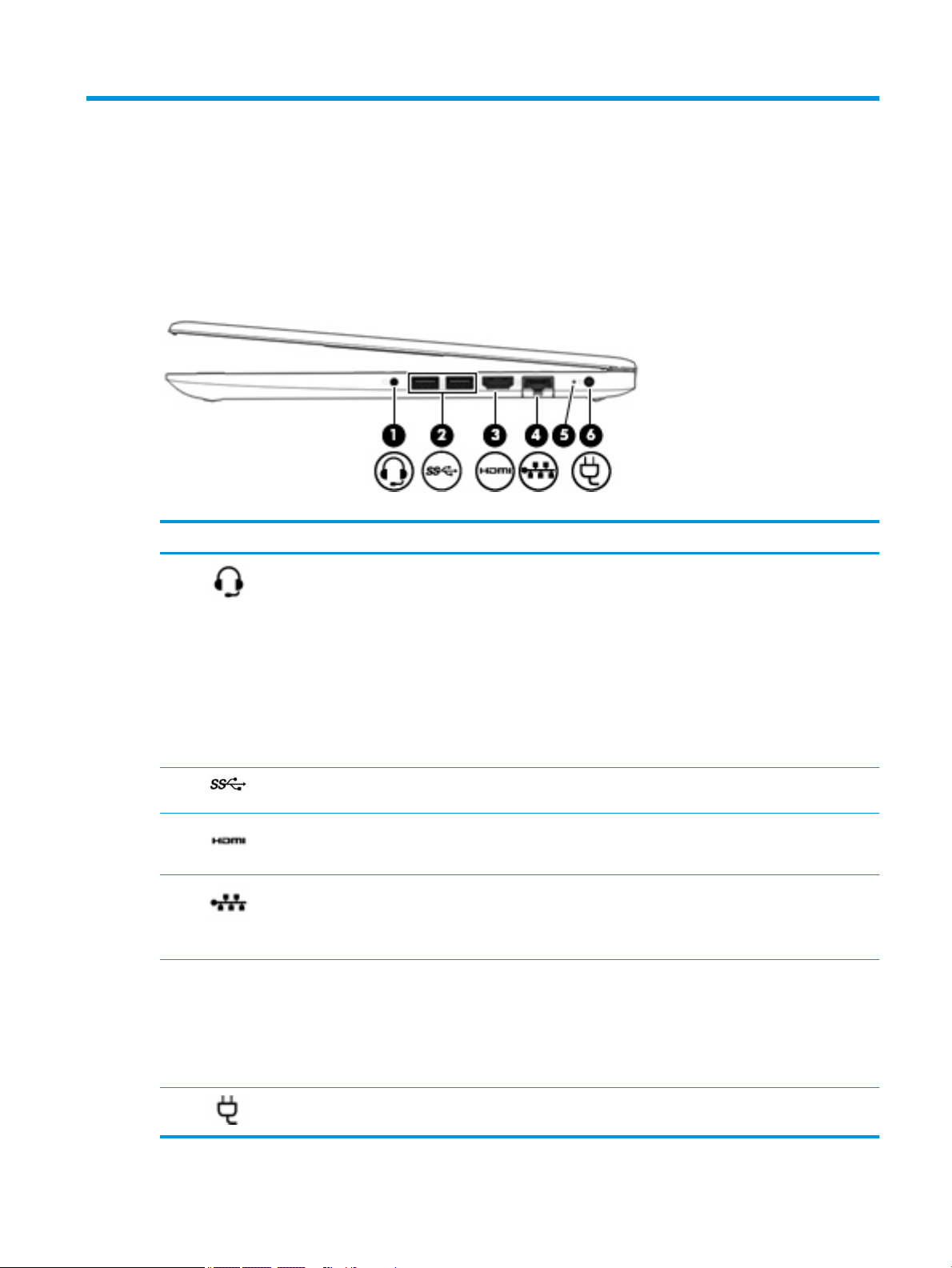
Right side
Table 2-1 Right-side components and their descriptions
Component Description
(1) Audio-out (headphone)/
Audio-in (microphone)
combo jack
(2) USB SuperSpeed ports (2) Connect a USB device, such as a cell phone, camera, activity tracker, or smartwatch,
(3) HDMI port Connects an optional video or audio device, such as a high-denition television, any
(4) RJ-45 (network) jack/
status lights
(5) AC adapter and battery
light
Connects optional powered stereo speakers, headphones, earbuds, a headset, or a
television audio cable. Also connects an optional headset microphone. This jack does
not support optional standalone microphones.
WARNING! To reduce the risk of personal injury, adjust the volume before putting on
headphones, earbuds, or a headset. For additional safety information, see the
Regulatory, Safety, and Environmental Notices.
To access this guide:
▲ Select the Start button, select HP Help and Support, and then select HP
Documentation.
NOTE: When a device is connected to the jack, the computer speakers are disabled.
and provide high-speed data transfer.
compatible digital or audio component, or a high-speed High-Denition Multimedia
Interface (HDMI) device.
Connects a network cable.
● White: The network is connected.
● Amber: Activity is occurring on the network.
● White: The AC adapter is connected and the battery is fully charged.
● Blinking white: The AC adapter is disconnected and the battery has reached a low
battery level.
● Amber: The AC adapter is connected and the battery is charging.
● O: The battery is not charging.
(6) Power connector Connects an AC adapter.
Right side 5
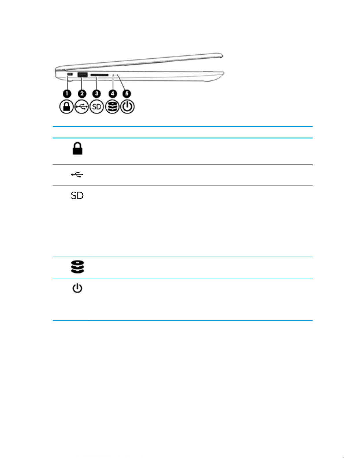
Left side
Table 2-2 Left-side components and their descriptions
Component Description
(1) Security cable slot Attaches an optional security cable to the computer.
(2) USB port Connects a USB device, such as a cell phone, camera, activity tracker, or smartwatch,
(3) Memory card reader Reads optional memory cards that enable you to store, manage, share, or access
NOTE: The security cable is designed to act as a deterrent, but it may not prevent
the computer from being mishandled or stolen.
and provides data transfer.
information.
To insert a card:
1. Hold the card label-side up, with connectors facing the computer.
2. Insert the card into the memory card reader, and then press in on the card until
it is rmly seated.
To remove a card:
▲ Pull the card to remove it from the memory card reader.
(4) Drive light (select products
only)
(5) Power light ● On: The computer is on.
● Blinking white: The hard drive is being accessed.
● Blinking: The computer is in the Sleep state, a power-saving state. The
computer shuts o power to the display and other unneeded components.
● O: The computer is o or in Hibernation. Hibernation is a power-saving state
that uses the least amount of power.
6 Chapter 2 Getting to know your computer
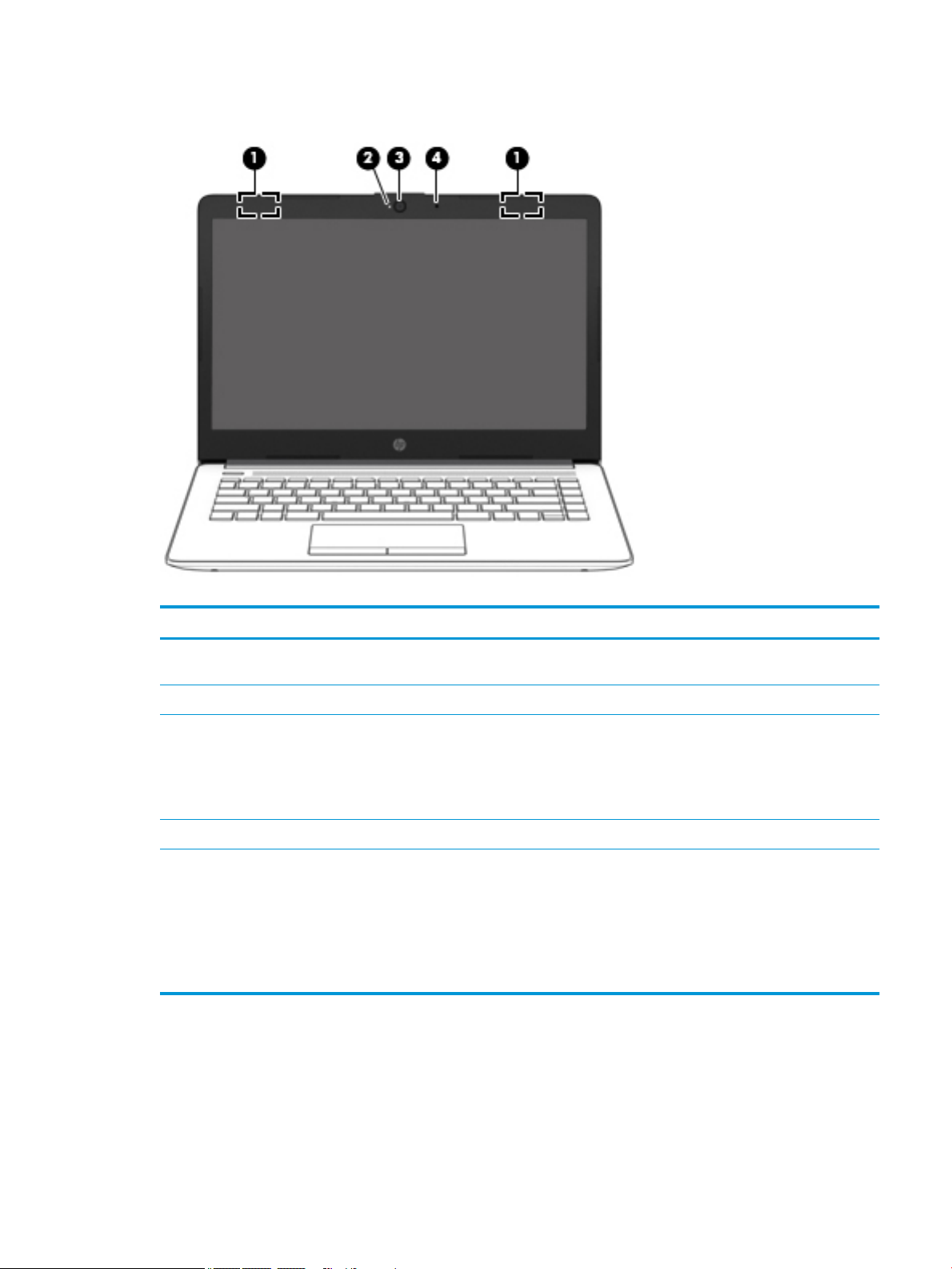
Display
Table 2-3 Display components and their descriptions
Component Description
(1) WLAN antennas* (1 or 2 depending on model) Send and receive wireless signals to communicate with wireless local
area networks (WLANs).
(2) Camera light On: The camera is in use.
(3) Camera Allows you to video chat, record video, and record still images. Some
cameras also allow a facial recognition logon to Windows, instead of
a password logon.
NOTE: Camera functions vary depending on the camera hardware
and software installed on your product.
(4) Internal microphone Records sound.
*The antennas are not visible from the outside of the computer. For optimal transmission, keep the areas immediately around the
antennas free from obstructions.
For wireless regulatory notices, see the section of the Regulatory, Safety, and Environmental Notices that applies to your country or
region.
To access this guide:
▲ Select the Start button, select HP Help and Support, and then select HP Documentation.
Display 7
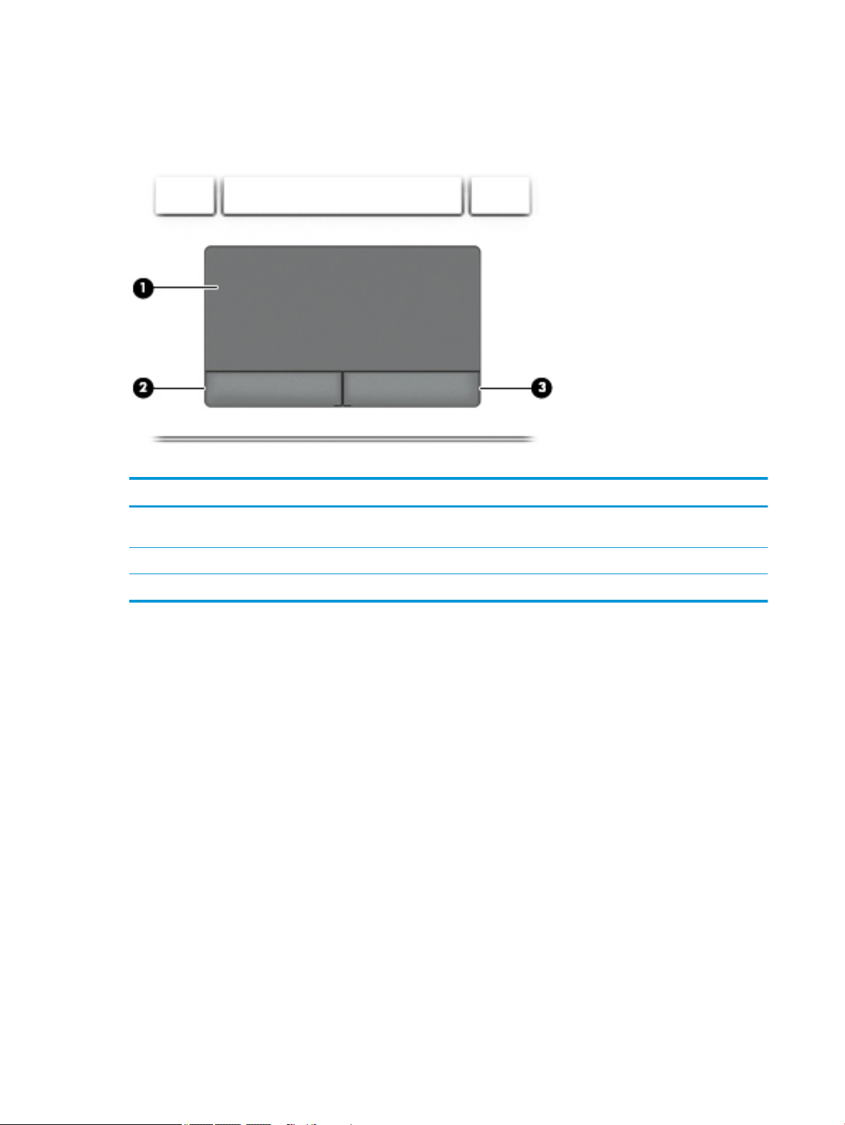
Keyboard area
TouchPad
Table 2-4 TouchPad components and their descriptions
Component Description
(1) TouchPad zone Reads your nger gestures to move the pointer or activate items
on the screen.
(2) Left TouchPad button Functions like the left button on an external mouse.
(3) Right TouchPad button Functions like the right button on an external mouse.
8 Chapter 2 Getting to know your computer
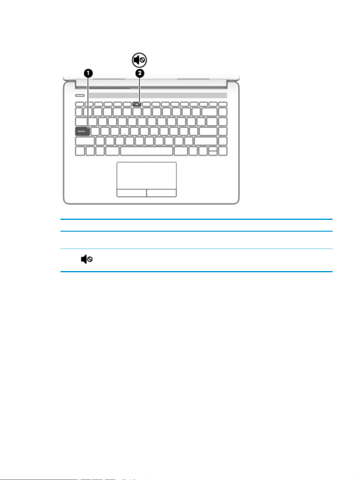
Lights
Table 2-5 Lights and their descriptions
Component Description
(1) Caps lock light On: Caps lock is on, which switches the key input to all capital
letters.
(2) Mute light ● On: Computer sound is o.
● O: Computer sound is on.
Keyboard area 9
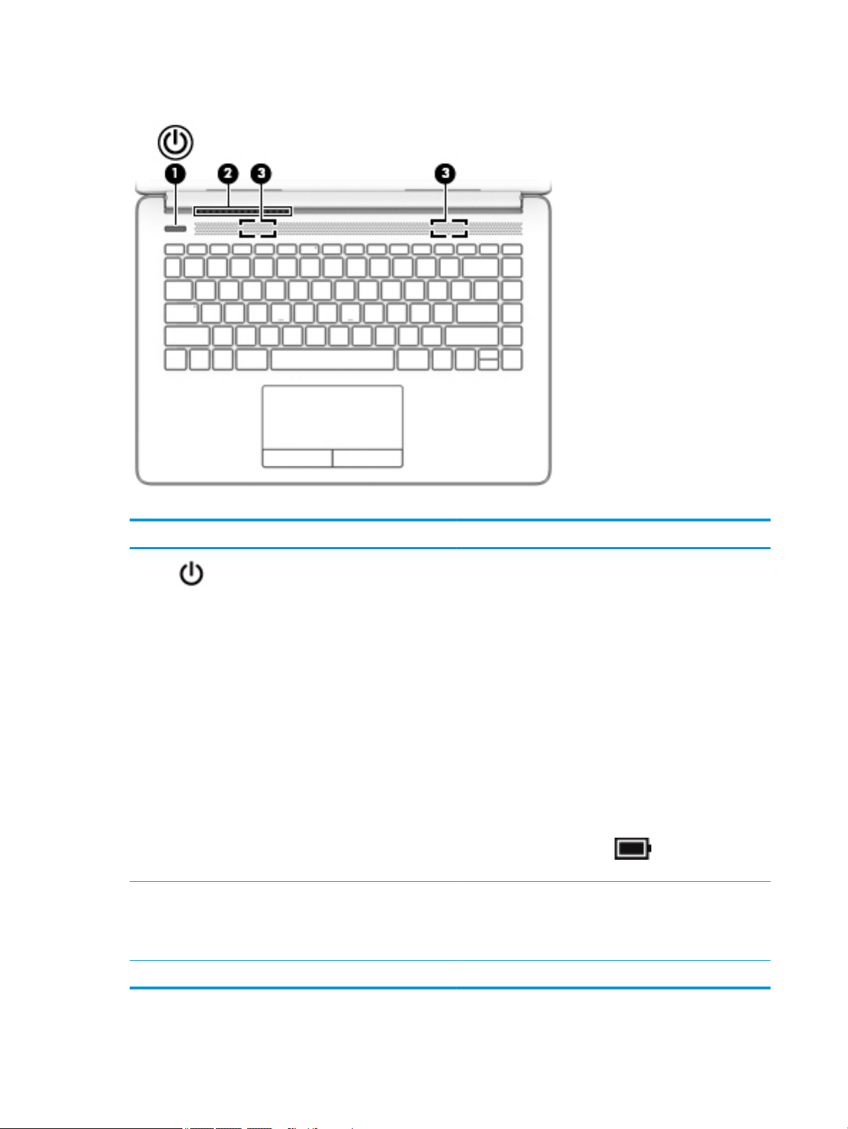
Button and speakers
Table 2-6 Buttons and speakers and their descriptions
Component Description
(1) Power button ● When the computer is o, press the button to turn on the
computer.
● When the computer is on, press the button briey to
initiate Sleep.
● When the computer is in the Sleep state, press the button
briey to exit Sleep.
● When the computer is in Hibernation, press the button
briey to exit Hibernation.
CAUTION: Pressing and holding down the power button results
in the loss of unsaved information.
If the computer has stopped responding and shutdown
procedures are ineective, press and hold the power button
down for at least 5 seconds to turn o the computer.
To learn more about your power settings, see your power
options:
▲ Right-click the Power icon , and then select Power
Options.
(2) Vent Enables airow to cool internal components.
NOTE: The computer fan starts up automatically to cool
internal components and prevent overheating. It is normal for
the internal fan to cycle on and o during routine operation.
(3) Speakers (2) Produce sound.
10 Chapter 2 Getting to know your computer
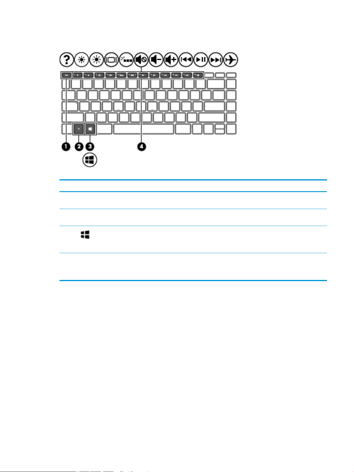
Special keys
Table 2-7 Special keys and their descriptions
Component Description
(1 esc key Displays system information when pressed in combination with
the fn key.
(2) fn key Executes specic functions when pressed in combination with
another key.
(3) Windows key Opens the Start menu.
NOTE: Pressing the Windows key again will close the Start
menu.
(4) Action keys Execute frequently used system functions.
NOTE: On select products, the f5 action key turns the keyboard
backlight feature o or on.
Keyboard area 11
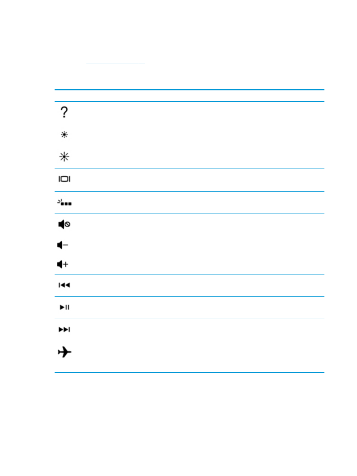
Action keys
An action key performs the function indicated by the icon on the key. To determine which keys are on your
product, see Special keys on page 11.
▲ To use an action key, press and hold the key.
Table 2-8 Action keys and their descriptions
Icon Description
Opens the “How to get help in Windows 10” webpage.
Decreases the screen brightness incrementally as long as you hold down the key.
Increases the screen brightness incrementally as long as you hold down the key.
Switches the screen image between display devices connected to the system. For example, if a monitor is
connected to the computer, repeatedly pressing this key alternates the screen image from the computer
display to the monitor display to a simultaneous display on both the computer and the monitor.
Turns the keyboard backlight o or on.
NOTE: To conserve battery power, turn o this feature.
Mutes or restores speaker sound.
Decreases speaker volume incrementally while you hold down the key.
Increases speaker volume incrementally while you hold down the key.
Plays the previous track of an audio CD or the previous section of a DVD or a Blu-ray Disc (BD).
Starts, pauses, or resumes playback of an audio CD, a DVD, or a BD.
Plays the next track of an audio CD or the next section of a DVD or a BD.
Turns the airplane mode and wireless feature on or o.
NOTE: The airplane mode key is also referred to as the wireless button.
NOTE: A wireless network must be set up before a wireless connection is possible.
12 Chapter 2 Getting to know your computer
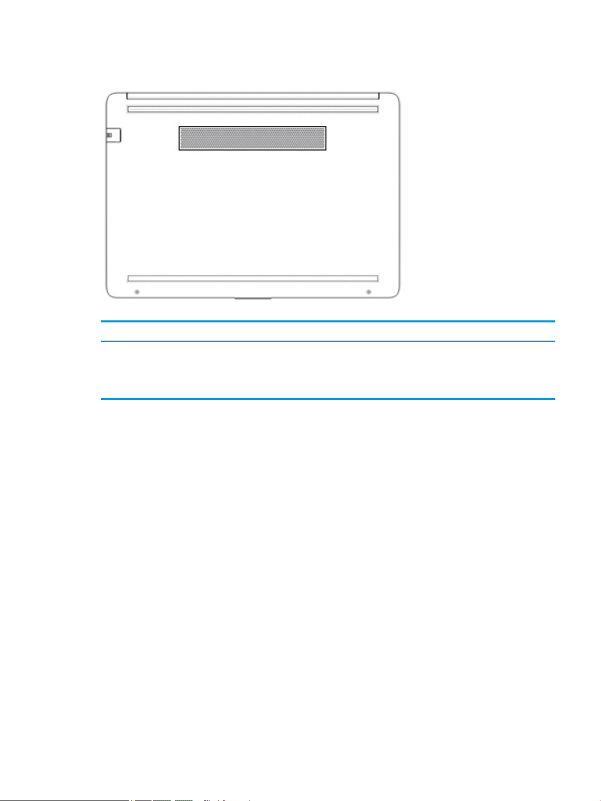
Bottom
Table 2-9 Bottom components and their descriptions
Component Description
Vent Enables airow to cool internal components.
NOTE: The computer fan starts up automatically to cool internal
components and prevent overheating. It is normal for the internal fan
to cycle on and o during routine operation.
Bottom 13
Labels
The labels axed to the computer provide information you may need when you troubleshoot system
problems or travel internationally with the computer. Labels may be in paper form or imprinted on the
product.
IMPORTANT: Check the following locations for the labels described in this section: the bottom of the
computer, inside the battery bay, under the service door, on the back of the display, or on the bottom of a
tablet kickstand.
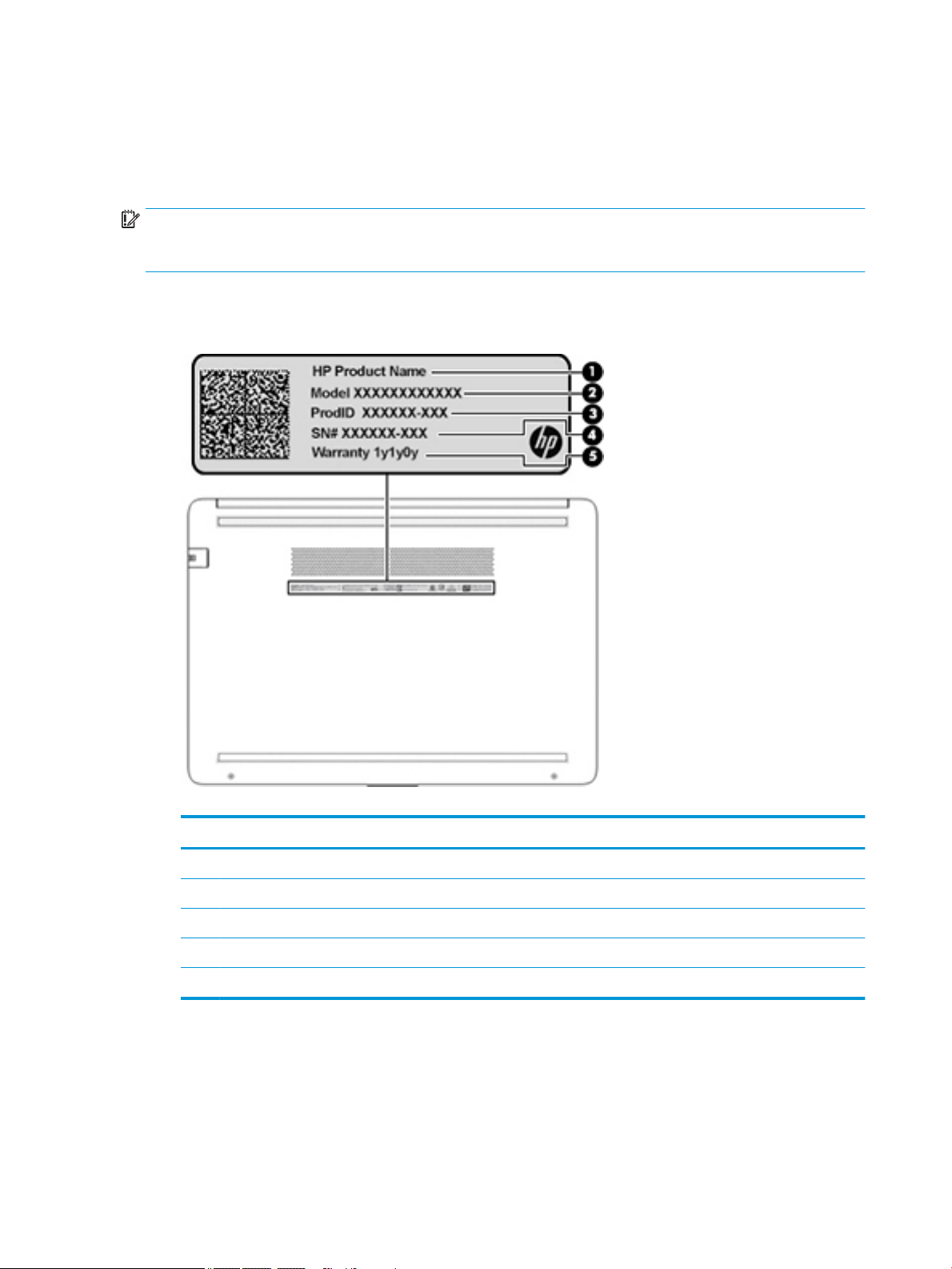
● Service label—Provides important information to identify your computer. When contacting support, you
may be asked for the serial number, the product number, or the model number. Locate this information
before you contact support.
Table 2-10 Service label components
Component
(1) HP product name
(2) Model number
(3) Product ID
(4) Serial number
(5) Warranty period
● Regulatory label(s)—Provide(s) regulatory information about the computer.
● Wireless certication label(s)—Provide(s) information about optional wireless devices and the approval
markings for the countries or regions in which the devices have been approved for use.
14 Chapter 2 Getting to know your computer
3 Illustrated parts catalog
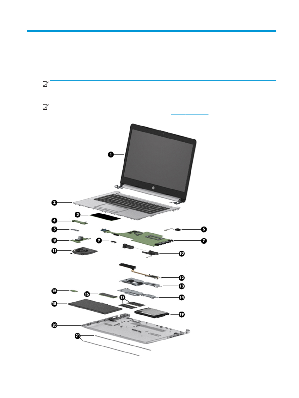
Computer major components
NOTE: HP continually improves and changes product parts. For complete and current information on
supported parts for your computer, go to http://partsurfer.hp.com, select your country or region, and then
follow the on-screen instructions.
NOTE: Details about your computer, including model, serial number, product key, and length of warranty,
are on the service tag at the bottom of your computer. See Labels on page 14 for details.
Computer major components 15

Table 3-1 Computer major components and their descriptions
Item Component Spare part number
(1) Display
NOTE: Displays are not spared as whole units. Display subcomponent spare parts are available.
For spare part information, see Display assembly subcomponents on page 18.
(2) Top cover/keyboard
NOTE: For a detailed list of country codes, see Top cover with keyboard on page 57.
For use in India L44060-D61
For use in Latin America L44060-161
For use in Taiwan L44060-AB1
For use in Thailand L44060-281
For use in the United States L44060-001
(3) TouchPad module L22586-001
(4) TouchPad button board L23197-001
(5) TouchPad button board bracket L23193-001
(6) Power connector cable (DC-in) L23188-001
(7) System board (includes integrated processor)
NOTE: All system board spare part kits include replacement thermal material.
All system boards use the following part numbers:
xxxxxx-001: Non-Windows operating systems
xxxxxx-601: Windows operating system
Not spared
AMD Ryzen 5-2500U processor L23394-xx1
AMD Ryzen 3-2200U processor L23393-xx1
AMD A6-9225 processor L23391-xx1
AMD E2-9000e processor L23389-xx1
(8) USB/card reader/power button board L23196-001
(9) System board hook L23206-001
(10) Speakers (includes cable) L23221-001
(11) Fan L23189-001
(12) Heat sink
For use in models with AMD Ryzen processors L23191-001
For use in models with AMD A6 processors L23385-001
(13) For use in fanless models with AMD E2-9000e processors L23384-001
(14) Fan insert (for use in fanless models) L23198-001
(15) WLAN module
Realtek RTL8822BE 802.11ac 2 × 2 Wi-Fi + Bluetooth 4.2 Combo Adapter (MU-MIMO supported) 924813-855
16 Chapter 3 Illustrated parts catalog

Table 3-1 Computer major components and their descriptions (continued)
Item Component Spare part number
Realtek RTL8821CE 802.11ac 1 × 1 Wi-Fi + Bluetooth 4.2 Combo Adapter (MU-MIMO supported) L17365-005
Realtek RTL8723DE 802.11bgn 1 × 1 Wi-Fi + Bluetooth 4.2 Combo Adapter L21480-005
Cables
(16) Solid-state drive
NOTE: For spare part information, see Mass storage devices on page 19.
(17) Memory modules (2400 MHz DDR4)
8 GB 820570-005
4 GB 820569-005
(18) Battery (3-cell, 48 Whr, 4.212 Ahr) L11119-855
(19) Hard drive
NOTE: For spare part information, see Mass storage devices on page 19.
(20) Bottom cover L44057-001
(21) Rubber feet L44059-001
Table
3-2 Cables and their descriptions
Item Component Spare part number
(1) USB/card reader/power button board cable L23186-001
(2) Display cable L23182-001
(3) TouchPad cable L23184-001
(4) TouchPad button board cable L23185-001
(5) Hard drive cable L23187-001
Cables 17
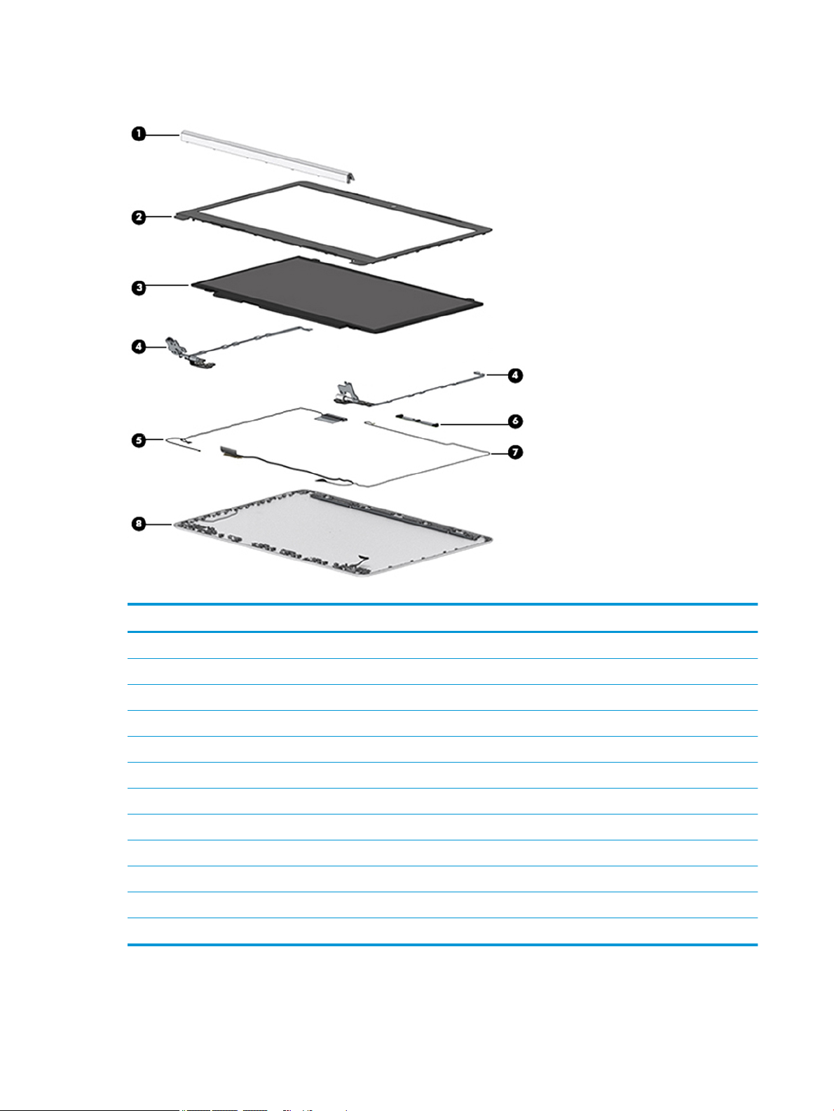
Display assembly subcomponents
Table 3-3 Display components and their descriptions
Item Component Spare part number
(1) Hinge cover L44058-001
(2) Display bezel L23181-001
(3) Display panel L48532-001
(4) Hinge Kit (includes left and right hinges) L23194-001
(5) WLAN antenna cable (included in Antenna Kit)
Single antenna, for use in models with an HD panel L23158-001
Dual antennas, for use in models with an HD panel L23159-001
(6) Camera module
HD camera L23237-001
VGA camera L23238-001
(7) Display cable L23182-001
(8) Back cover L44056-001
18 Chapter 3 Illustrated parts catalog
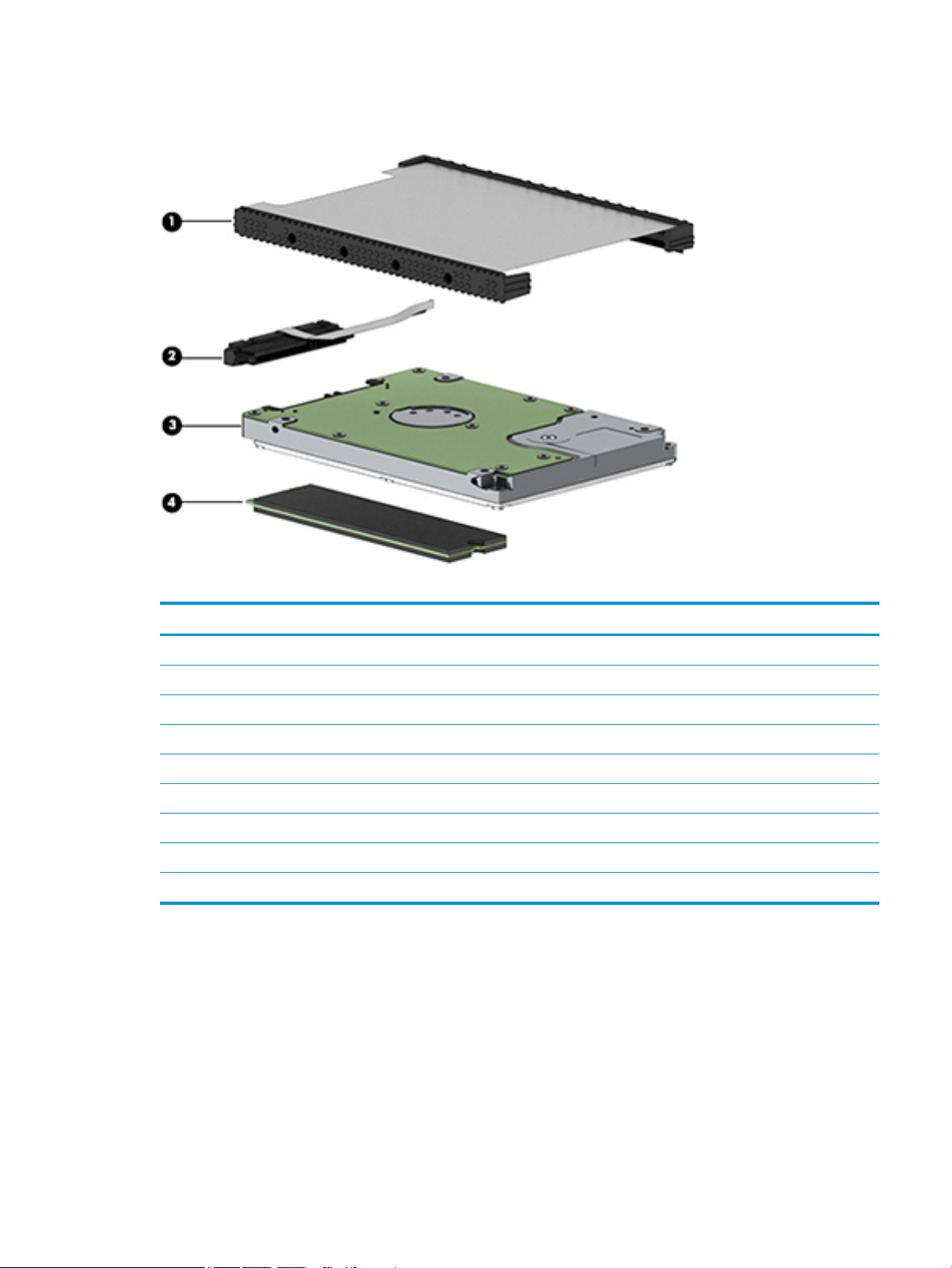
Mass storage devices
Table 3-4 Mass storage devices and their descriptions
Item Component Spare part number
(1) Hard drive cover L23219-001
(2) Hard drive cable L23187-001
(3) Hard drive, 7 mm
1 TB, 5400 rpm 762990-005
500 GB, 7200 rpm 703267-005
500 GB, 5400 rpm 778186-005
(4) Solid-state drive (M.2)
256 GB, SATA-3, TLC L23223-001
128 GB, SATA-3, TLC L23222-001
Mass storage devices 19

Miscellaneous parts
Table 3-5 Miscellaneous parts and their descriptions
Component Spare part number
AC adapter
65 W AC adapter, nPFC, SMART, RC, 4.5 mm, EM 913691-850
45 W AC adapter, nPFC, SMART, RC, 4.5 mm, non-slim 741727-001
Power cord, C5, conventional, 1.0 m
For use in Argentina L19357-001
For use in Australia L19358-001
For use in Europe L19361-001
For use in India L19363-001
For use in Italy L19364-001
For use in North America L19367-001
For use in the People’s Republic of China L19368-001
For use in Taiwan L19372-001
For use in Thailand L19371-001
For use in the United Kingdom L19373-001
Screw Kit L23220-001
HP HDMI-to-VGA adapter 701943-001
HP USB-to-Gigabit RJ-45 adapter 829941-001
Top load case 679921-001
20 Chapter 3 Illustrated parts catalog
 Loading...