

Page 1
E
DGE
®
I
NSTALLATION
R
OUTER
M
ODULE
G
UID
E
FOR
E
THERNET
Part No. 17-00590-3
Published August 1996
Page 2

3Com Corporation ■
California ■
©3Com Corporation, 1996. All rights reserved. No p ar t o f t his
documentation may be reproduced in any form or by any means or
used to make any derivative work (such as translation,
transformation, or adaptation) with out permis sion f rom
3ComCorporation.
3Com Corporation reserves the right to revise this documentation,
and to make changes in content from time to time, without
obligation on the part of 3ComCorporation to provide notification of
such revision or change.
3Com Corporation provides this documentation without warranty
of any kind, either implied or expressed, including, but not
limited to, the implied warranties of merchantability and fitness
for a particular purpose. 3Com m ay make improvements or
changes in the products and the programs described in this
documentation at any time.
UNITED STATES GOVERNMENT LEGENDS:
If you are a United States government agency, then this
documentation and the softwa re describ ed herein are provided to
you subject to th e following rest ricted right s:
For units of the Department of Defense :
Restricted Rights Legend:
Government is subject to restrictions as set forth in subparagraph (c)
(1) (ii) of the Restricted Rights in Technical Data and Computer
Software clause at 48 C.F.R. 52.227-7013. 3Com Corporation.
For civilian agencies:
Restricted Rights Legend: Use, reproduction, or d isclosure is sub ject to
restrictions set forth in s ubpa ragraphs (a) through (d ) o f th e
Commercial Computer Software - Restricted Rights clause at
48C.F.R. 52.227-19 and the limitations set forth in
3ComCorporation’s standard commercial agreement for the
software. Unpublished rights reser ved under the copyright l aws of
the United States.
If there is any software on removable media described in this
documentation, it is furnished under a license agree ment included
with the product as a separate document, in the hard-copy
documentation, or on the removable media in a director y file
named LICENSE.TXT. If you are unable to locate a copy, please
contact 3Com and a copy will be provided to you.
Federal Communications Commission Notice
This equipment was tested and found to comply with the limits f or a
Class A digital device, pursuant to Part 15 of the FCC Rules. These
limits are designed to provide reasonable protection against harmful
interference wh en the e quipment is oper ated in a com mercial
environment. This equipment generates, uses, and can radiate radio
frequency energy and, if not installed an d used in accordance with
the instruction manual, may cause harmful interference to radio
communications. Operation of this equipment in a residential area is
likely to cause harmful interference, in which case you must correct
the interference at your own expe nse.
95052-8145
5400 Bayfront Plaza ■
Use, duplication, or disclosure by the
Santa Clara,
Canadian Emissions Requirements
This Class A digital apparatus meets all requirement s of the Canadian
Interference-Causing Equipm ent Regulations.
Cet appareil numérique de la classe A respe cte toutes les exigence s
du Règlement sur le matériel brouilleur du Canada.
EMC Directive Compliance
This equipment was tested and conforms to the Council
Directive 89/336/EEC for electromagnetic compatibilit y. Conformity
with this directive is based upon compliance with the following
harmonized standards:
EN 55022 – Limits and Methods of M easureme nt o f
Radio Inter ference
EN 50082-1 – Electromagnetic Compatibility Generic Immunity
Standard: Residential, Commercial, and Light Industr y
Warning:
This is a Class A product. In a d omes tic environment, this
product may cause radio interference, in which case you may be
required to take adequate measures.
Compliance with this directive depends on the use of shielded
cables. [optional shielde d cable s s tatement]
VCCI Class 1 Compliance
This equipment is in the 1st Class categ ory (information equip me nt
to be used in commercial or industrial areas) and conforms to the
standards set by the Voluntary Control Council for Interference by
Information Technology Equipment aimed at p reventing r adio
interference in commercial or industrial areas.
Consequently, when the equip ment is used in a reside ntial a rea or in
an adjacent area, radio interference may be caused to radio and TV
receivers, and so on.
Read the instruc tions for correc t handling.
Fiber Cable Classification Notice
Use this equipment only with fiber cable classified by Unde rwriters
Laboratories as to fire and smoke characteristics in accordance with
Section 770-2(b) and Section 725-2(b) of the National Electrical Code.
UK General Approval Statement
The ONcore Switching Hub, ONline System Concentrator, and
ONsemble StackSystem Hub are manufactured to the International
Safety Standard EN 60950 and are approved in the UK under the
General Approval Number NS/G/12345/J/100003 for indirect
connection to the pub lic telecommun i cation network.
Trademarks
Unless otherwise indicated, 3Com registered trademarks are
registered in the United States and may or may not be registered in
other countries.
ii
Page 3

3Com, Boundary Routing, CardBoard, CardFacts, EtherDisk, EtherLink,
EtherLink II, LANp lex, LAN sentr y, LinkBuilder, NETBuilde r,
NETBuilder II , NetFacts, ONcore, ONsemble, ORnet, Parallel Tasking,
SmartAgent, TokenLink, Transcend, TriChannel, and ViewBuilder are
registered trademarks of 3Com Corporation.
3Com Laser Library, 3Com OpenHub, 3TECH, FDDILink, FMS,
MultiProbe, NetProbe, ONdemand, ONline, PowerRing, StackJack,
StackWay, and SwitchCentral are trademarks of 3Com Corporation.
3ComFacts and Ask3Com are ser vice marks of 3Com Corporation.
The 3Com Multichannel Architecture Communications System is
registered under U.S. Patent Number 5,301,303.
AT&T is a registered trade mark of American Telephone and Telegraph
Company.
AppleTalk is a registered trade mark o f Ap ple Computer, Inc.
Apollo and Apollo Do main are regi stered tradema rks of A pollo
Computer, Inc.
Banyan and VINES are registered trademarks of Banyan Systems, Inc.
Cisco and Cisco Systems are registered trademarks of Cisco Systems,
Inc.
AGS+, ASM, IGRP, Interne tworking Operating Sy stem, IOS, MGS, and
UniverCD are trademarks of Cisco Systems, Inc.
CompuServe is a registe red trademark o f CompuSer ve, Inc.
ProComm is a registered trademark of DATASTORM TECHN OLOGIES,
INC.
DATASTORM is a trademark of DATASTORM TECHNOLOGIES, INC.
DEC, DECnet, DELNI, POLYCENTER, VAX, VT100, VT220, and the Digital
logo are trademarks of Digital Equipment Corporation.
Hayes is a registered trademark of Hayes M ic rocomputer Products.
OpenView is a registered t rademark of Hewlett-Pack ard Company.
Intel is a registered trademark of Intel Corporation.
AIX, IBM, and N etV iew a re registered tradem arks o f International
Business Machines Corporation.
Microsoft, MS-DOS, and Windows are registered trademarks of
Microsoft Corp.
Motorola is a registered trademark of M otorola Corporation.
V30 is a trademark of NEC Corporation.
NetWare and Novell are registered trademarks of Novell,
Incorporated.
IPX is a trademark o f N ovell, Incorp orated.
OSF and OSF/Motif are registered trade marks of Open Software
Foundation, Inc.
Retix is a reg istered trade m ark of Ret ix.
ROUTERXchange is a trademark of Retix.
Solaris, SPARCengine, Sun, Sun Microsystems, and SunSoft are
registered trademarks of Sun Microsystems, Inc.
ONC, OpenWindows, SunNet Manager, and SunOS are trademarks of
Sun Microsystems, Inc.
SPARCstation and SPARCompiler are licensed exclusively to Sun
Microsystems, Inc.
OPEN LOOK is a registered trademark of UNIX System Laboratories,
Inc.
UNIX is a reg istered trade mark in the Unite d States and othe r
countries, licensed exclusively through X/Open Company, Ltd.
Xerox is a registered trademark of Xerox Corporation.
Xerox Network System, and XNS are trademarks of Xerox
Corporation.
Other brand and product names may be registered trademarks or
trademarks of their respective holders.
Guide written by John Dohert y. Edited by Jill Angel. Production by
Tracey Taylor.
iii
Page 4

Page 5

C
ONTENTS
A
BOU
T THIS GUID
Introduction 9
Audience 9
How to Use This Guide 9
Conventions 10
Relate d Docum ents 12
3Com Doc ument s 12
Cisco Documen ts 13
Reference D ocum en ts 13
1
I
NTRODUCTION
Product Over view 1-1
Edge Router Mod ule Operation 1-1
Edge Router Mod ule Architec ture 1-3
Edge Router Mod ule Features 1-5
Software Options 1-5
Topology Switching 1-7
Network Reliab ility 1-7
IOS Router Software Updates 1-8
Memor y Upgrades 1-9
E
2
I
NSTALLING THE EDGE ROUTER MODULE
Installation Flowchar t 2-2
Precautionar y Procedu res 2-3
Quic k Ins tallat ion 2 -3
Quick Installation for Un manag ed Hu bs 2-4
Quick Installation for Man aged Hubs 2-5
Unpackin g Procedures 2-6
Verifying Jumper Plug Positions 2-7
v
Page 6

Configuring DIP Switches 2-8
Configuring the ONline Ca rrier DIP Switches 2-8
Selecting a Ne twork 2-9
Isolating the O Nline Edge R outer Mod ule 2-9
Configuring the ONco re Carrier DIP Switche s 2-9
Enabling or D isabling NVR AM Co nfigurat ion 2-10
Selecting a Ne twork 2-11
Installing the ONlin e Edge Router Module 2-12
Installing the ONcore Edg e Router Mod ule 2-13
3
C
ONFIGURIN
Managed Conf iguration O ver vi ew 3-2
3Com Management Modules 3-2
Using Management Commands 3-2
Using ONdemand NCS 3-3
Carrier Configura tion Tasks 3- 3
Atta ch ing a Ma na ge me nt Termi na l 3- 3
Configuring the Carrie r in a Managed ONline Hub 3-4
Selecting a Ne twork 3-4
Saving the Config uration 3-4
Configuring the Carrie r in a Managed ONco re Hub 3-5
ONcore Carrier Configu ration Sources 3-5
DMM Settings 3- 5
Carrier NVRA M Settings 3-6
Carrier DIP Switch Settings 3-6
Carrier Defa ult Settings 3-6
Hot Swapping an ONcore Module 3-7
Determining the Configurat ion Source 3-8
Selecting a Ne twork 3-8
Saving the Config uration 3-9
Configuring the Edge R outer Engine 3-9
Attaching a Terminal to the Console Port 3-9
Using the Terminal to Configure the Edge Router Eng ine 3-11
G THE EDGE ROUTER MODULE
vi
Page 7

4
M
ONITORING EDGE ROUTER MODULE OPERATIO
Monitoring Edge Rou ter M odule Ope ration 4-1
Showing Module Configuration and Status 4-3
Using the SHOW MODULE Command 4-4
Using the SHOW PORT Command 4-6
5
T
ROUBLESHOOTIN
Troubleshooting Start up Problem s 5-2
Troubleshooting Router-Spec ific Problem s 5-2
Troubleshooting Mailbox Inter face Problems 5-2
Troubleshooting 3Com Car rier Problem s 5-2
Troubleshooting Network Conn ectivity Problem s 5-3
Troubleshooting WAN Connectivity Problems 5-4
Correcting Operating M alfunction s 5-5
A
S
PECIFICATIONS
General Specifications A-2
Electrical Spec ifications A-2
Environmental Specifica tions A-3
Mechanical Spec ifications A-3
Hub Capacities A-4
ONline Hub Capac ities A -4
ONcore Hu b Capac ities A-4
Cable Pinouts A-5
Console Port Pinout s A-6
DTE Console Port A-6
Mini-DIN to DB-25 Mod em Cable A-7
Auxiliar y Port Pinouts A-8
Mini-DIN to DB-25 Mod em Cable A-8
DB-2 5 Null Mode m Ca ble A- 9
Serial Por t Pinout s A-9
EIA-530 DTE Synch ronous Serial Cab le Pinouts A-10
RS-232 DTE and DCE Serial Cable Pinou ts A -11
RS-449 DTE and DCE Serial Cable Pinou ts A -12
V.35 DTE and DCE Se rial Cable Pinouts A-13
X.21 DTE and DCE Serial Cable Pinouts A-14
G
N
vii
Page 8

B
T
ECHNICA
Online Technical Services B-1
3Com Bulletin Board Servic e B- 1
World W i de We b S it e B-3
3ComForum on CompuServe B-3
3ComFacts Automated Fax Ser vice B-3
Support From Your Network Supplier B-4
Support From 3Com Corporation B-5
Returning Products for Repair B-5
Accessing the 3Com ISD MIB B-6
Contacting 3Com ISD Technical Publicat ions B-6
I
NDE
L
IMITE
L SUPPOR
Access by Analog Modem B-2
Access by Digital Mode m B-2
X
D WARRANTY
T
viii
Page 9

A
BOU
T
T
HIS
G
UID
E
Introduction
Audience
How to Use This Guide
This guide desc ribes ho w to install and configure a 3Com ® ONline™ or
ONcore® Edge Router mo dule into the 3Com ONlin e System Concentrator
or ONcore Switching Hub. In addition, this guide provides troubleshooti ng
suggesti ons in case a problem arises with the m odule.
If the inform ation in t he relea se note s shippe d w ith your p roduct dif fers from
the info rmat ion in this gu ide, follow the releas e note instruc tion s.
This guide is intended for the followi ng peopl e at your site:
■
Network mana ger or administrator
■
Trained hard ware instal ler or ser vice pe rsonn el
Table 1 shows the locati on of specific i nformation .
Table1
If you are looking for:
General informa tion about the Edge Router module
Description of the mo dule a rchitec ture
Typical appl ications o f the Ed ge Rou ter mod ule
Features of the Ed ge Rou ter mod ule
An overvie w of th e insta llation and con figur ation pr ocess
Procedures for unpac king the Edge Route r modu le
Proced ures for prepar in g to instal l the Edge Rou ter mo dule
Procedures for in stalling the Edg e Route r module
An overvie w of th e mana ged con figur ation pr ocess
Proced ur es for at tachin g a ma na geme nt ter min al
Procedures for conf iguring Edg e Route r carrier pa rameters
How to Use This Guide
Turn to:
Chapter 1
Chapter 2
Chapter 3
Page 10

10
A
BOU
T THIS GUID
E
Conventions
Table1
Procedures for conf iguring Edg e Route r engin e parameter s
Information for mon itoring Edge Rou ter mod ule LEDs
How to Use Th is Guide (continue d)
Chapter 3
Chapter 4
Procedures for d isplayin g modu le config urati on and sta tus
Information on troubl eshootin g the Ed ge Router modul e
Information not cov ered in the rest of the gu ide
Chapter 5
Appendixes A-B
Table2 and Table3 list conventions used throughout this guide.
Table2
Icon
Table3
Graphic Convention s
Type
Information No te
Caution
Warning
Text Conventions
Description
Information no tes call a ttention to importa nt feature s or
instructions.
Cautions aler t you to per sonal saf ety risk, sys tem
damage, or loss of data.
Warnings ale rt you to th e risk of severe person al injur y.
Convention
“Enter” vs. “Type”
Description
When the word “ente r” is used in this guide , it means type
something, the n pres s the R eturn or Enter key. D o not
press the Retu rn or Enter key w hen an i nstruction simply
says “type.”
Page 11

Conventions
11
Table3
Text Conventions (continu ed)
Convention
“Syntax” vs. “Com mand”
Text repr esente d as
screen display
Text repr esente d as
commands
Keys
Italics
Description
When the wor d “syn tax” i s used in thi s guide, it ind icates
that the ge neral fo rm of a co mmand syntax is prov ided.
You must evalu ate the syntax an d supply the appropr iate
port, path, value , addres s, or stri ng. For ex ample:
Enable RIP IP by usi ng the follow ing sy ntax:
SETDef ault !<port> -RIP IP CONTro l =
Listen
In this example, you mu st supply a port number for
!<port>.
When the wor d “c omma nd” is us ed in this g uide, it
indicates that all vari ables in th e comma nd have bee n
supplied and you c an enter the comman d as sho wn in
text. For exampl e:
Remove the IP addre ss by ente ring the fol lowing
command:
SETDef ault !0 -IP NETadd r = 0.0.0.0
For consistency and clarity, the full-form syntax (uppe r- and
lowercase lett ers ) is p rovid ed. H ow ev er, yo u can enter t he
abbreviate d form of a co mman d by typing onl y the uppe rc ase
portion a nd suppl ying t he ap prop riat e port, pat h, a ddre ss ,
value, and so on. You can en ter th e co mman d in ei ther up per -
or lowercase lett ers at the promp t.
This typeface
is used to represen t displ ays tha t
appear on yo ur ter minal s creen. For example:
NetLog in :
This typeface
is used to represe nt comm ands th at
you enter. For example:
SETDef ault !0 -IP NETadd r = 0.0.0.0
When spec ific keys a re r eferr ed to in the text, th ey are
called out by th eir labels, s uch as “ the Return key” o r “the
Escape key,” o r they ma y be show n as [Return] or [Esc ].
If two or m ore keys a re to be press ed simulta neously, the
keys are linked with a plus sign (+). For ex ample:
Press [Ctr l]+[ Alt]+ [Del].
Italics
are used to d enote
new terms
or
emphasis
.
Page 12

12
A
BOU
T THIS GUID
E
Related Documents
3Com Documents
This sec tion provides informa tion on sup portin g docum entation, includi ng:
■
3Com Documents
■
Cisc o Do cum ents
■
Reference D ocuments
The following documen ts provide additi onal infor mation on 3Co m
products :
ONline Sys tem Concentrato r Installati on an d Op eration Gui de
— Provid es
informatio n on the install ation, operation , and config uration of the ONli ne
System Concen trator. This guid e also describes the principa l features of the
ONline Fault-Tolerant Control ler Mod ule.
ONline Ethern et, Token Ring, or FDDI Ma nagemen t Modu le User ’s Guide
Provides inform ation on the ONline Manag ement M odule’s operation,
installati on, and confi guration. Thi s guide also de scribes the software
comman ds assoc iated with the M anagem ent Mo dule.
ONcore Switching Hub Installation and Operation Guide
— Provides
informatio n on the installatio n, operation , and configuratio n of the ONcore
Switching Hub. This guide also describes the principal features of the
ONcore Fault-Tolerant Controll er Module.
—
ONcore Distributed Management Modu le User’s Guide
— Provides
informatio n on the ONcore Di stributed Manag ement Modu le’s operation,
installati on, and confi guration. Thi s guide also de scribes the software
command s associated with th e Distri buted Mana gemen t Module.
ONcore Distributed Management Modu le Commands Guide
— D escri bes
each manag ement com mand by providing de tails on co mmand for mat,
use, and description.
For a complete list of 3Com documents, contact your 3Com representative.
Page 13

Related Docume nts
13
Cisco Doc uments
Refere nce
Documents
Cisco® CD- ROM docu ments desc ribe comm ands and other softw are-related
informatio n you need to operate th e Edge Router mo dule.
The followi ng docum ents suppl y related bac kground i nformation :
Case, J., Fedor, M., S coffstall , M. , and J. Davin, The Simple N etwork
Management Protocol
, RFC 1157, University of Tennessee at K noxville,
Performan ce Systems Internation al and the MIT Labo ratory for Computer
Science, M ay 1990 .
Rose, M., and K. McCloghrie, Structure and Id entification of Man agemen t
Information f or TCP/I P-based Internets
, RFC1155, Performance Systems
Internati onal and Hu ghes LA NSystems, May 1990.
Page 14

Page 15

1
I
NTRODUCTION
This chapter provid es an introduc tion to the 3Com ® Edge Rou ter module.
This chapter co ntains the following section s:
■
Pro du c t
■
Edge Router M odule Features
Over view
Product Overview
Edge Rou ter
Modu le Operation
The Edge Router module is a
module joi ntly develop ed by 3Com and Cis co Systems Inc.
This sec tion provides informa tion on the fol lowin g topics:
■
Edge Router M odule O peration
■
Edge Router Modu le Arc hitecture
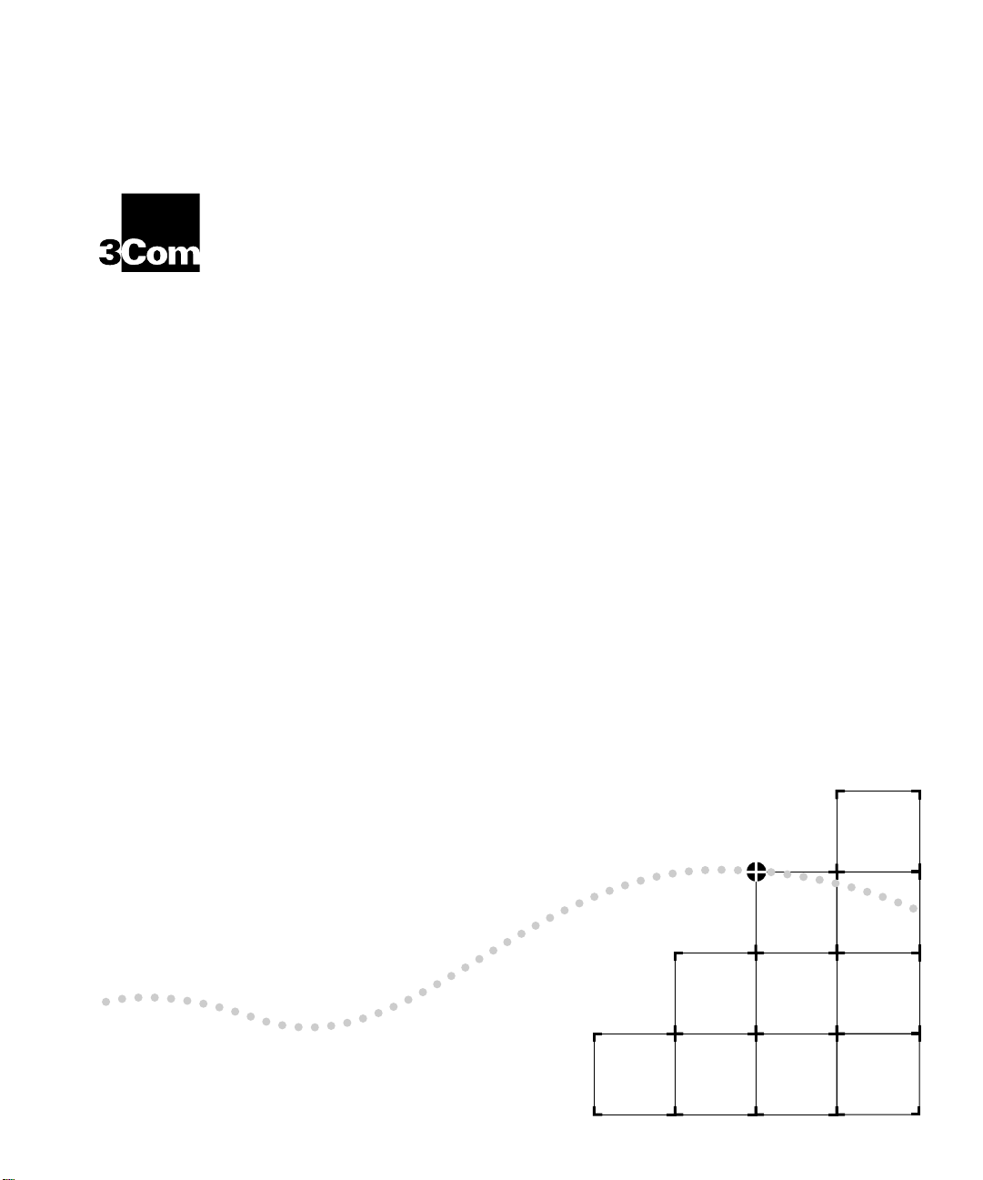
The Edge Router mod ule (Figure 1-1) is desig ned to:
■
Connect co rporate networ ks and increas e wide area connectivit y.
■
Support both synchronous and asynchrono us routing over serial lin ks using
one local area n etwork (LAN) and up to three wide area networ k ( WAN)
connec tions.
■
Provide flexi ble netw ork ing con nec tion s in mu ltiprotoco l envi ronm ents.
■
Sit at the network ’s logical and physical edg e, either at a remote site or
centr al f a cili ty.
serial por t-to-Eth ernet LA N
interconne ct
Page 16
1-2
C
HAPTE
R
1:
I
NTRODUCTION
Edge Router Module
Console Port
Auxiliary
Port
High Speed
WAN Port
High Speed
WAN Port
Network
Backplane
Ethernet
LAN
Figure 1-1
Typical Edge Rou ter Modul e Connec tions
The router mod ule run s Cisco standard so ftware a nd fully intero perates w ith
the:
■
3Com ONlin e
■
Cisco lo cal and remo te router s erve rs, suc h as the AGS+
Ethernet Router Module
, MGS
, and the
Cisco 3000, 4000, 4500, and 7000 series routers.
Page 17

Product Overview
1-3
Edge Rou ter
Module
Architec ture
Each Edge R outer modul e co nsists o f th e fol lowing compon ents:
■
Carrier
– Provides conn ectio n
s to o ne o f th ree 3 Com sw itchin g hub
products .
■
Engine
■
Interface Conn ector
– Provides Ethe rnet-to-WAN por t connec tions.
– Conn ect s the carr ier to th e eng ine. B oth the c arr ier
and the eng ine have an inter face connec tor.
The engine m ounts to one of thre e carrier ty pes to form an Edge Router
module for the ONlin e or ONcore hub produc ts.
The ONline Edge Router module can also be installed in an ONcore
Switching Hub. For de tailed infor mation on inst alling ONlin e m odules in
ONcore switch ing hubs , refer to the
Operat io n G u ide
(Documen t Numb er 17-003 62).
ONcore Swit ching Hub In sta llation an d
Page 18
1-4
C
HAPTE
R
1:
I
NTRODUCTION
Edge Router
module en gi ne
Figure1-2 show s the architectur e of each Edge Ro uter modul e type.
ONline
System Con ce ntrator
ONline carrier
ONcore Int egrated
System
ONcore carrier
Edge Router
module en gine
Figure 1-2
Edge Rou ter Modul e Arc hitec ture
Page 19

Edge Router Module Features
1-5
Edge Router
Modu le Features
Software Options
This section describe s the major fea tures of the Edge Router module,
incl udi ng:
■
Software Options
■
Topolog y S witch ing
■
Network Reliabi lity
■
IOS Router Softw are Updates
■
Memor y U pgrades
The Edge Router mod ule is available with one of the following software
feature sets:
■
IP/IPX
■
Desktop
■
Desktop pl us IBM®
■
Enterprise
The compo nents that mak e up each softw are feature set are liste d in
Table 1-1.
Page 20

1-6
C
HAPTE
R
1:
I
NTRODUCTION
Table1 -1
Software Feature Sets
Featur e
Category
LAN Support
WAN Serial
Support
WAN Services
WAN
Optimization
IP Routing
IBM Support
Feature Se t
IP/IPX
IP, Bridging,
LAN Exten sion
Host Software,
Novell® IPX
™
Desktop
Includes
IP/IPX
features plus:
DECnet™ IV,
AppleTalk®
Desktop plus IBM
Same as Desktop
Enterpr ise
Includes De sktop plus
IBM feature s pl us:
DECnet V, XNS, Banyan
VINES®, OSI, Apollo®
Domain
Phase 1 a nd 2
Dual Synchr onous
Ports,
and Singl e Async hron ous
Auxiliar y Port
HDLC, PPP, X.25, Frame Relay, ISD N, SMDS
Header and lin k co mpr ess ion , dial -on-de man d , dial bac kup, ban dwid th-on-d ema nd,
custom and pri ority queuin g, acces s lists, acc ess securit y
RIP, IGRP, Enhanc ed IGRP™, OSPF, BGP, EGP, PI M
Includes sta ndard
features plu s: ES-I S and
IS-IS
N/A
N/A
Remote source-r oute
bridging , proxy,
explorer, loc al
acknowle dgement,
SNA local LU address
prioritiz ati on,
Includes De sktop plus
IBM feature s pl us: seria l
tunne ling for SDLC
Transport, SDL C
link-l evel supp ort,
SDLLC, TG/ COS, QLLC
adminis trativ e filte ring,
NETBIOS name
caching, NETBIOS
access control filtering
Network
Manag em ent
Protocol
Translation
Autoinsta ll, SNMP, TELN ET
N/A
N/A
N/A
TELNET, LAT, rlogin,
TN3270, X.25
Page 21

Edge Router Module Features
1-7
Topolog y Switching
Network R eliability
Using topolo gy switchin g you can:
■
Switch the ONli ne Edge Ro uter module among any of three Eth ernet
networks (channels) on the hub backplane
■
Switch the ONcore Edg e Router mod ule among any of eight Ethern et
networks (channels) on the hub backplane
You per form topol ogy switch ing using :
■
Network mana gement mo dule comm ands
■
Simple Networ k Managem ent Protocol (SNMP)
You do no t have to swap cables or m ove the Edge Router m odule to move
the routing or br idging func tions to a differen t network w ithin an ONline or
ONcore hub. You can e nter a com ma nd th roug h one of th e 3 Com
management modules and the network change is made automatically.
The Edge Router mod ule lets you implem ent several le vels of reliability in
your network as follows:
■
By routing the E dge Router m odule’s seri al and auxi liary por ts in paral lel,
you can create up to three redun dant links.
■
If the primar y link fails, you can ha ve up to two backup link s in place to
ensure appl ication availabil ity.
These links can also imp lement load -balanci ng to enhance n etwork
perfor mance. An exam ple of a relia ble networ k configurati on is show n in
Figure 1-3.
Page 22
1-8
C
HAPTE
R
1:
I
NTRODUCTION
Ethernet LAN
Edge Router ModuleEdge Router Module
Public
Switched
Telephone
Network
IOS Router
Softwa re Updates
Console
Port
Dial-Up
Link
Figure 1-3
Aux
Port
WAN Port
Primary
Link
Main Site Router
Main Site Network Connections
WAN Port
Network R eliabil ity Config uration
Remote Site
Secondary
Link
Main Site
The IOS software in the Edge Router module en gine can be upd ated by
purchasing fi eld-up gradeab le softw are dis tributi on k its . Up date your
module to the latest 3Com release of IOS software by downloading new
code to flash m emory on the module. New updates are shi pped
automatical ly as part of the 3Com 1-year Router S oftware Subscr iption
Servi ce or you can pur chase it from 3Com as a single un it update.
Page 23

Edge Router Module Features
1-9
You can also purchase an upgrade kit to upgrade your IP/IPX, Desktop, or
Desktop plus IBM software to a vers ion with an enh anced feature se t.
Contact your 3Com reseller o r 3Com Custom er Support for more
informatio n and part num bers.
Memor y U pgrad es
The Edge Router module provide s the capability to increase m emory to
meet the requirem ents of larg e routing table configuration s.
Memor y is confi gured on the Edge Router m odule to match th e
requireme nts of the s elected IOS softwa re feature set. Table 1-2 lists th e
base memor y con figuratio ns for each software fe ature set.
Table1-2
Memory Type
IOS ( Flash EPR OM )
Data (DRAM)
Memory Con figuration s
Feature Set
IP/IPX
4 MB (expandable to 8 MB)
4 MB (expandable to 16 MB)
Desktop
Desktop
plus IBM
8 MB
Enterpr ise
6 MB
(expandable to
18 MB)
Page 24

Page 25

2
I
NSTALLING THE
M
ODULE
This chapter co ntains the following section s:
■
Installati on Fl owchar t
■
Precautionar y Proced ures
■
Quick Instal lation
■
Unpack ing Procedures
■
Verifying J umpe r Plug Positi ons
■
Configuri ng DIP Switch es
■
Installing th e ONline Edge Router Module
■
Installing th e ONcore Edge Router Mod ule
E
DGE
R
OUTER
Page 26
2-2
C
HAPTE
R
2:
I
NSTALLING THE EDGE ROUTER MODULE
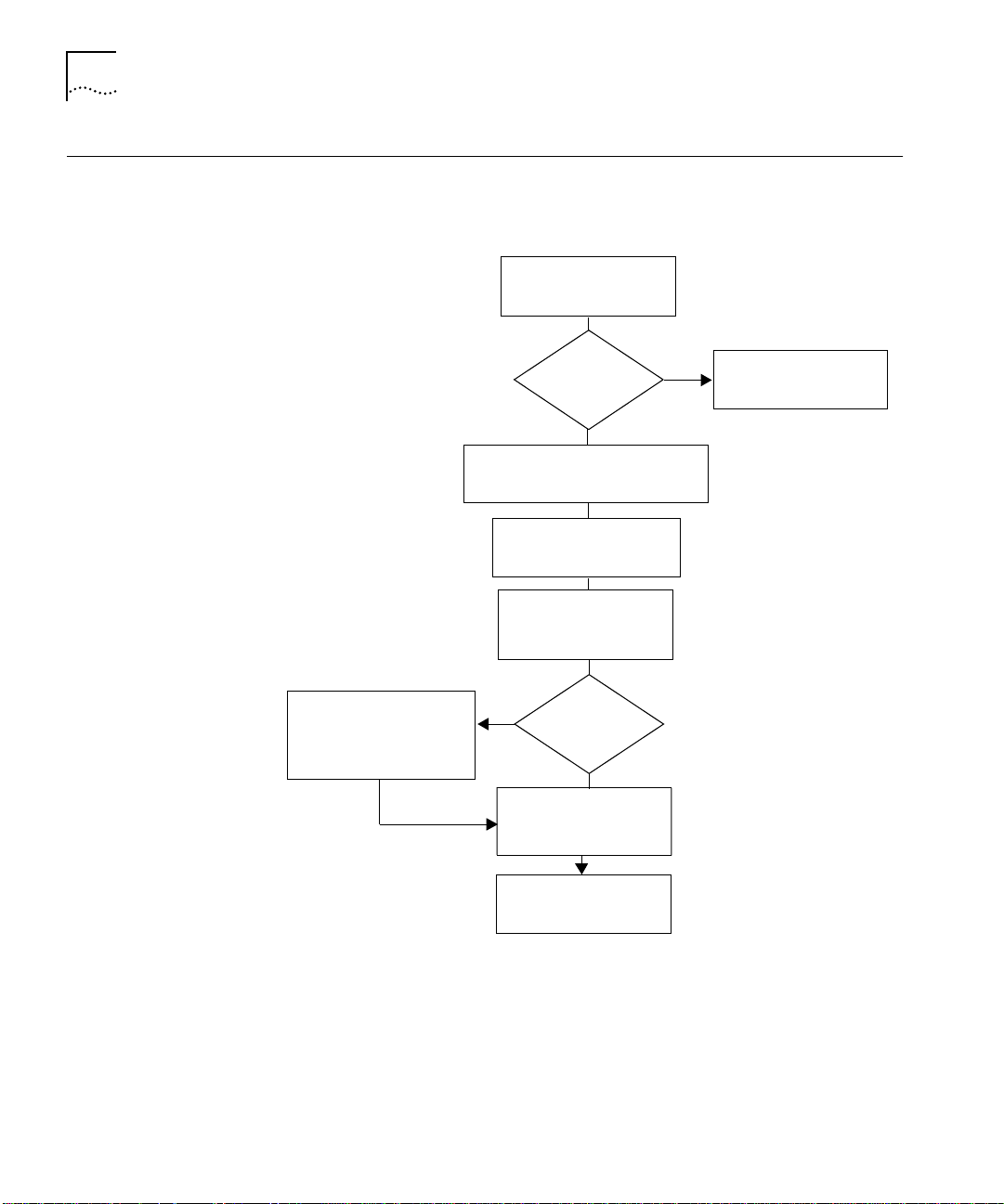
Installation Flowchart
The flowchar t in Figure 2-1 id entifies the steps required to install and
configu re the Edge Route r module.
Read Pre ca utionar y
Procedure s
(page 2-3)
Configure the carrier using
management commands
(page 3-2)
Experi en ce d
installer?
Unpack the Edge Router module
(page 2-6)
Configure DIP switches
(page 2-8)
Install the Edge Router
module
(page 2-12)
Yes
Managed
Hub?
Configure the Edge
Router engine
(page 3-9)
Yes
No
No
Go to Quick Installation
(page 2-3)
Figure 2-1
Installation complete
Flowchar t for Insta lling and Confi gur ing the Edge Router Module
Page 27

Precautionary Procedures
2-3
Precautionary
Procedures
Quick Installation
Electrostati c discharg e (ESD) can dam age static-s ensitive dev ices on circui t
boards. Follow these precauti ons when you handle an Edge Router modu le:
CAUTION
: Do not remove th e prod uct from an y an tistat ic wrapp ing u ntil
you are ready to inspect or install the module.
Handle Edge Rout er module s by the faceplate only.
CAUTION:
To avoid damaging the Edge R outer m odule w ith ES D, use prope r
grounding techniques. Before unpack ing, you should:
■
Use a foot strap and g rounded mat, or wear a g rounded stati c discharge
wrist strap.
■
Touch a grounded source just before you remove the Edge Rou ter module
from the sh ippin g car ton.
This section outline s the steps ne cessar y to com plete the ins tallation of the
Edge Router module in unman aged or managed ONline or ONcore hubs. If
you are already familiar wi th the procedures required to instal l a modul e in
your 3Com hub type, us e this tab le as a chec klist. Other wi se, use the
procedures sp ecified in th e remaind er of this chapter to install the Edge
Router modu le.
If you encoun ter proble ms w hile fo llowin g the q uick in sta llation steps,
consult th e trou bleshoot in g techn iques in C hapte r 5.
Page 28

2-4
C
HAPTE
R
2:
I
NSTALLING THE EDGE ROUTER MODULE
Quick In stallat ion
for Unmanaged
Hubs
Follow the gene ral steps outlin ed in Table2-1 to instal l and config ure the
Edge Router m odul e in an u nmana ged ONli ne o r ONcore hub.
Table2-1
Step
1
2
3
4
5
6
7
Quick Insta llation for Unma naged Hubs
Procedur e
Unpack the mod ule.
Verify the j umper plug position s on
the base and expans ion engines.
Configu re the ca rrier fo r oper ati on in
an un manag ed hu b us ing DI P
switch settings.
Insert the module into an open slot
in the hub.
Attach a ma nage ment ter minal to
the Edge Ro uter mod ule c onsole
port.
Configu re the eng ine pa rameters
using C isc o Sys tems setup
command.
Attach WAN cables to th e 60-pin
universal WA N conn ector s on the
front pan el.
Refer to:
Unpa cki ng Pro ced ure s o n pa ge 2- 6
Verifying Jumpe r Plug Positions on
page2-7
Config uring DIP S witc hes on pag e 2-8
The appropria te insta llation in struc tions
for your hub type in thi s chapter
Configuri ng the Edge Router En gine on
page3-9
Cisco Syste ms Ge tting St arte d Gu ide
Cable Pi nouts on page A-5
Page 29

Quick Installation
2-5
Quick In stallat ion
for Managed Hu bs
Follow the gene ral steps outl ined in Table 2-2 to instal l and confi gure the
Edge Router module in a managed ONline or ONcore hub.
Table2-2
Step
1
2
3
4
5
6
7
8
Quick Insta llation for Ma naged Hubs
Procedur e
Unpack the mod ule.
Verify the j umper plug position s on
the base and expans ion engines
Insert the mo dule into a n open slot in
the hub.
Configu re the ca rrier for possible
operation in an unma naged hub.
Attach a ma nage ment ter minal to the
Edge Router cons ole po rt.
Configu re the carrier using netw ork
managemen t commands.
Configu re the eng ine pa rameters
using C isc o Sys tems setup
command.
Attach WAN cables to th e 60-pin
universal WA N conn ector s on the
front pan el.
Refe r t o:
Unpacking P rocedur es on p age 2- 6
Verifying J umper Plug P ositions on
page 2-7
The appropriate ins tallation
instructions for your hu b type in this
chapter
Config uring DIP Switc hes o n pag e 2-8
Configuring the Ed ge Router Engine
on page 3-9
Config uring th e Car rier in a Man aged
ONline Hub on page 3 -4
or
Config uring th e Car rier in a Man aged
ONcore Hub on page 3-5
Cisco Systems Gett ing Started Gu ide
Cable Pino uts on pag e A-5
Page 30

2-6
C
HAPTE
R
2:
I
NSTALLING THE EDGE ROUTER MODULE
Unpacking Procedures
To unpack the Edge Router module:
1
Verify that the mod ule is the m odel you ord ered by check ing the mo del
number li sted on th e s ide o f th e s hipping ca rton.
Note that the product mod el number pri nted on the shipping box d iffers
from the model n umber on the pro duct. The m odel num ber on the
shipping box con tains the prefix 3 C9.
2
Remove the mod ule, in its antis tatic shield ing bag, from the sh ipping
carton.
3
When you unpa ck the Edge Ro uter module, you sh ould:
■
Use a foot strap and grounded mat, or wear a grounded stati c discharge
wrist strap.
■
Touch a g rounded sourc e just before you rem ove the Edge Ro uter
module from the carto n.
CAUTION
: To avoid damagin g the E dge Ro uter m od ule with ESD, use prope r
grounding tech nique s.
Remove the mod ule fro m th e an tistatic bag and inspec t it for damag e.
Always handl e modules by the facepl ate, being careful not to touch th e
componen ts. If the module ap pears to be damag ed, return it to the
antistatic s hielding bag, rep ack it in the shippi ng carton , and contact yo ur
local su pplier.
4
Verify that the contents of the shipment are complete. The shipment
contents are as follows:
■
Edge Router module
■
Rack-mounting kit
■
Edge Router Mo dule In stallati on Gui de for Ethern et
■
Release Notes for the Edge Ro uter module
5
Store the shippi ng cartons and antistati c wrapping so that you can
repackag e the produc t for storage or shi pment.
Page 31

Verifying Jumper Plug Positions
2-7
Verifying Jumper
Plug Positions
Verify the jumper plug pos itions on the ONline or ONcore Edge Router
module before proceed ing with the instal lation procedure.
The Edge Router module is equippe d with several jumpe r plugs. The
jumpers are facto ry-set to the approp riate settings. Do
not
modify t he
jumper se ttings, except to restore the se ttings to the req uired po sitions.
CAUTION:
If you modify any of th e factor y-set j umper positions, t he Edge
Router module may not operate properly.
Table 2- 3 lists the default jumpe r plug positions for the Edge Router
module. If you suspec t that any of the jum pe r position s have been ch ang ed,
verify th e pl ug pos itions usi ng Table 2 -3.
.
Table2-3
Jumper
J1
J2
J4
J5
J9
J10
J12
J13
J14
J15
J16
J17
Default Jumper Plug Settings
Jumper Plug Position
ETH INT
Removed
Insert ed
Removed
Removed
WAN 0 E XT
WAN 1 E XT
Removed
Insert ed
Removed
Insert ed
Insert ed
Page 32

2-8
C
HAPTE
R
2:
I
NSTALLING THE EDGE ROUTER MODULE
Configuring DIP Switches
Configuring the
ONline Carrier DIP
Switches
DIP switches let you select the back plane netw ork used by an ONline or
ONcore
Edge Ro uter modu le.
Even if you use a network management module to manage your hub, it is
recommended that you con figure t he carrie r DIP swit ches t o ensure p roper
network assign ment s in the even t of manage me nt mod ule fa ilure.
This section describes:
■
Configuri ng the ONli ne Carrier DIP Switches
■
Configuri ng the ONcore Ca rrier DIP Switches
ONline carr ier DIP switches let you select the back plane netwo rk used by
the Edge Router modu le. Modules set to the same network in the hub can
communi cate with each othe r.
The ONline Edge Router module can also be installed in an ONcore hub. For
more infor ma tion, r efer to the
Operat io n G u ide
(Document Number 17-00362).
ONcore Switc hing Hub Installation and
Page 33

Configuring DIP Switches
Figure2-2 shows the ONli ne carrier DIP switch location .
ON
1234
2-9
Configuring the
ONcore Carrie r DIP
Switches
Figure 2-2
ONline Ca rrier DIP Swi tch Locatio n
Selecting a Network
Use Table 2- 4 to select a networ k by using the DIP switches.
Table2-4
Network Selection
Ethernet_1 (default)
Ethernet_2
Ethernet_3
Isolated
Isolating th e
ONline Net work Sele ction DIP Sw itch Setti ngs
Switch Set tings
Switch 1
ON
ON
OFF
OFF
ONline
Edge Route r Module
Switch 2
ON
OFF
ON
OFF
Switch 3
ON
ON
ON
ON
Switch 4
ON
ON
ON
ON
To isolate the Edge R outer modul e from all backpl ane netwo rks, set the DIP
switches to the Is olated positio n as defined i n Table 2-4.
ONcore carrier DIP switches allow yo u to set the followi ng configuratio n
parameters:
Page 34

2-10
C
HAPTE
R
2:
I
NSTALLING THE EDGE ROUTER MODULE
■
Enabling or Disabling NVRAM Confi guration
■
Selecting a Netwo rk
Figure2- 3 shows the ONcore carrier DIP switch locati on.
ENG 1
ENG 2
CH SEL 0
CH SEL 1
CH SEL 2
CH SEL 3
NV SEL
CH SEL 0
CH SEL 1
CH SEL 2
CH SEL 3
NV SEL
ONOFF
0
1
2
3
4
5
6
7
8
9
Figure 2-3
ONcore Ca rrier DIP Switc h Location
Enabling or Disabling NVRAM Config uration
Two NV SEL DIP switches control whether the ONcore Edge Router module
uses con figuration s ettings sto red in NVRAM (n on-volati le mem ory).
■
Switch 4 provid es the N VRAM se lection for engin e bay 1 (top).
■
Switch 9 provid es the N VRAM se lection for engin e bay 2 (bot tom).
Page 35

Configuring DIP Switches
If the NV S EL DIP swi tch is :
■
ON (en abl ed)
– The Edge Router mo dule uses confi guration settings
stored in its NVRAM . If NVRAM does no t contain configura tion set tings, the
Edge Router modul es are assigned to the Isolate_1 n etwork.
■
OFF (d isabl ed)
– The Edge Router module uses DIP switch settings.
Selecting a Network
In an unman aged ONcore hub, the DIP swi tches determ ine the networ k
setting (unless NVRAM con figuratio n settings are en abled).
1
To selec t a netw ork:
Set the switch es according to Table2-5.
2-11
Table2-5
Network
Selection
Ethernet_1
(default)
Ethernet_2
Ethernet_3
Ethernet_4
Ethernet_5
Ethernet_6
Ethernet_7
Ethernet_8
Isolate_1
Isolate_2
Isolate_3
Isolate_4
ONcore Networ k Selec tion DI P Switch Settin gs
Switch Set tings
CH SEL 0
ON
OFF
ON
OFF
ON
OFF
ON
OFF
ON
OFF
ON
OFF
CH SEL 1
ON
ON
OFF
OFF
ON
ON
OFF
OFF
ON
ON
OFF
OFF
CH SEL 2
ON
ON
ON
ON
OFF
OFF
OFF
OFF
ON
ON
ON
ON
CH SEL 3
ON
ON
ON
ON
ON
ON
ON
ON
OFF
OFF
OFF
OFF
Switch co mbina tions not listed in Table 2-5 sele ct Is olate_ 1.
2
Disable NV RAM by setting the NV SEL DIP swi tch to the off position .
Page 36

2-12
C
HAPTE
R
2:
I
NSTALLING THE EDGE ROUTER MODULE
Installing the ONline Edge Router Module
This section des cribes how to instal l the ONline Edge Router module in an
ONline hub.
If you a re ins talling:
■
An ONcore Edge Router mo dule, refer to Installing the ONcore Ed ge Router
Module on page2-13.
■
An ONline Edge Rou ter module in an ONcore hub, refer to the
Switching H ub Ins tallati on an d Op eration Gui de
(Docume nt Number
ONcore
17- 003 6 2)
You d o not need to pow er off th e ONli ne h ub to install or remove the Edge
Router modu le. You can inser t the mo dule while the hub is operati ng (this
is called a hot swap).
To insta ll the Edge Route r module in an ONl ine hub:
1
Use one of the following prope r grounding technique s when you install the
Edge Router module:
■
Properly ground yourself prior to handling the module.
■
Attach a static wrist g uard to yours elf or touch a groun ded static mat
prior to h andling the mod ule.
2
Locate an open slot in th e ONline hub. If necessar y, remove a blank panel
on the hub to expose a slot.
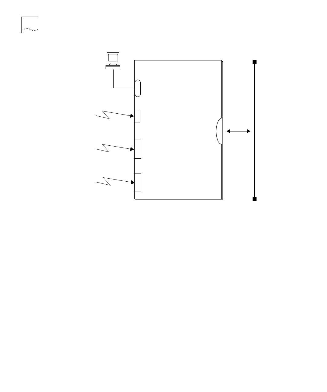
3
Inser t the module into the slot’s board guides and slide it into the hu b by
pressing fir mly at the top and bo ttom of the faceplate. M ake sure the
connec tors are well-seated into the back plane of the hu b.
Page 37

Installing th e ONcore Edge Route r Module
4
Using your fin ger s, tighten the tw o s prin g-loa ded s crew s on the front of the
module faceplate (Figure 2-4). Do not over tighten.
2-13
Installing the
ONcore Edge
Router Module
Board guid e
Screws
Figure 2-4
Boar d guide
Facepl at e
Installing the Edg e Router M odule in an ON line Hu b
Hub ba ck plane
You do not nee d to power off the ONcore hub to install or remove the
Edge Router mod ule. You can inse rt the modul e while the hub is o perating
(this is cal led a hot swa p).
To install the Edge Router module in an ONcore hub:
1
Use one of the following prope r grounding technique s when you install the
Edge Router module:
■
Properly ground yourself prior to handling the module.
■
Attach a static wrist g uard to yours elf or touch a groun ded static mat
prior to h andling the mod ule.
If you already have a management terminal connected to your ONcore hub,
you can verify th e hub has enou gh p ower for the n ew E dge R oute r module
by entering the SHOW P OWE R BUDGET command. R efer to App endix A for
details on power requ irements.
Refer to the ONcore
Distributed Mana geme nt Mod ule C ommand s Guid e
information o n the SHOW POWE R BUDG ET com mand.
2
Locate an open slot in the ONcore hub. If necessar y, remove a blank panel
to expose a slo t.
for
Page 38

2-14
C
HAPTE
R
2:
I
NSTALLING THE EDGE ROUTER MODULE
3
Inser t the module into the board guides at the top and bottom of the slot
and slide it into th e hub by pressin g firmly at a poi nt slightly bel ow the
center of th e facepl ate (Figur e2-5).
Figure 2-5
Installing the Edg e Router M odule in an ON core Hub
Page 39

4
Close the ejectors (Figure2-6).
Installing th e ONcore Edge Route r Module
2-15
Open ed
ejector
Figure 2-6
5
Using your fin ger s, tighten the tw o s prin g-loa ded s crew s on the front of the
Opened and Clo sed M odu le Eje ct ors
Closed
ejector
Edge Router mod ule faceplate (do not over tighten) .
Page 40

Page 41

3
C
ONFIGURIN
R
OUTER
This chapter co ntains the following section s:
■
Managed Confi gura tion O ver vie w
■
Attaching a Management Terminal
■
Configuring the Carrier in a Managed ONline Hub
■
Configur ing the Car rier in a Manage d ONcore Hub
■
Configuring the Edge Router Engine
If you are installing the Edge Router module in an unmanaged ONline or
ONcore hu b, you mu st con figure t he carrier usin g DIP switc hes. Refe r to
Configuring D IP Switch es on pa ge2-8. When you fin ish s etting t he DIP
switches , go to Co nfigur ing th e Ed ge Rou ter E ngin e on p ag e 3-9.
M
G THE
ODULE
E
DGE
Page 42

3-2
C
HAPTE
R
3:
C
ONFIGURIN
G THE EDGE ROUTER MODULE
Managed Configuration Overview
3Com Management
Modules
You can manage an ONline or ONcore carrier using a network management
module installed in the same hub.
This se ction provi des a b rief over v iew of th e follow ing topics :
■
3Com Mana gement M odules
■
Using Manag ement Com mands
■
Using ONdemand NCS
■
Carrier Configuration Tasks
You can m anage the ONl ine or ONcore carrier throu gh SNMP o r
managem en t co mm and s if a m ana ge ment mod u le i s in stal led.
Management modules for ONline and ONcore hub types include:
■
ONline
– An ONline Ethern et Man agemen t Modu le (EMM) ru nni ng software
Version v4.10 or later ins talled in the same hub as the Edge Router mo dule
or a Token Ring Management Module (TRMM) running software
Versionv3.30 or later installed in the s ame hub as the Edge Router mo dule.
■
ONcor e
– A Distributed Management Module (DMM) running software
Version v2.30 or later ins talled in the same hub as the Edge Router mo dule.
Using Ma nageme nt
Commands
You can use man agement c ommand s to make bas ic changes to carri er
configuratio n settings. For complete ins truction s on using man agement
command s to manage the car rier, refer to the guide for the m anagemen t
module for your platfo rm.
ONline management documentation includes:
■
ONline Ethern et Man agemen t Modu le Instal lation and O peration Guide
(Document Num ber 17-0008 7)
■
ONline Management Commands Guide
■
ONline Token Ring M anagem ent Mo dule User ’s Guide
(Do cum en t Nu mbe r 17 -0 040 3)
(Document Num ber 17-0021 1)
For ONcore management, refer to the
Module Comman ds Gui de
(Document Num ber 17 -00372)
ONcore Dist ributed Ma nagem ent
Page 43

Attaching a Manageme nt Terminal
3-3
Using ONd emand
NCS
Carrier
Configuration Tasks
Attaching a
Management
Terminal
The 3Com ONdem and™ Networ k Control Sy stem (NCS) is an SNMP
manager w ith a graphical user inter face. For instructi ons on using
ONdemand NCS to manage the carrier, refer to one of the follow ing
documents :
■
Transcend Enterprise Manager O Ndema nd Mana gement f or Mult i-Function
Hubs, Version 4.0 f or UNIX
■
ONdeman d Network Control System f or Window s User ’s Guide
(Do cum en t Nu mb er 17 -0 03 20)
(Document
Num be r 17- 004 72)
To configure an ONline or ONcore Edge Router ca rrier in a managed hub:
1
Attach a manageme nt terminal to the consol e port of the netw ork
management module (TRMM, DMM, or EMM).
2
Use the manag ement termi nal to configure the carrier us ing 3Com netw ork
management commands.
Use a terminal (or workstation running a terminal emulation program) to
configure the E dge Router car rier.
Attach a terminal to a port on the netw ork manag ement module to
configu re or modify hub param eters, incl uding:
■
Selectin g networ ks for modu les in the hub
■
Changing configur ations
■
Reportin g the conditio n of any module in th e hub
For information on attaching and configuring a management terminal for
your hub type, refer to the docum ents specified in Using M anagemen t
Commands on page3-2.
Page 44

3-4
C
HAPTE
R
3:
C
ONFIGURIN
G THE EDGE ROUTER MODULE
Configuring the Carrier in a Managed ONline Hub
Selec ting a Ne twork
This section describes how to use network management commands to
configure ONli ne carrier s install ed in an ONline Sys tem Concentrator. This
section contains the fol lowing topics :
■
Selecting a Netwo rk
■
Saving th e Con fi gurati on
When you install the carrier in a hub with a management module installed,
the networ k defau lts t o isola ted mo de (Isolat e_1) . You must assign a
network as described below.
The engine conn ects to the back pla ne through a ca rrier modu le por t on the
ONline carr ier. You can assig n the carrier module por t to:
■
One of three E the rnet back plane netw or ks
■
Isolated mod e
For details on ba ckplan e netw orks, refer to the
Installatio n and Opera tion Guide
(Document Number 17-00417).
ONline Syste m Concentrator
To assign th e carrier mod ule ports to a ne twork using th e network
managem ent softw are, use th e following comma nd:
Saving the
Configuration
ONline > s et port
slot.po rt
networ k {ether net_1 ... _3 }
{isolat ed_1}
For example, the followi ng comma nd sets port 1 in the ONline carrier
installed i n slot 3 to the Etherne t 2 backpla ne networ k:
ONline > set po rt 3.1 networ k ethernet_ 2
Port 03 .01 network id set to ETHERNET _2
To save config uration ch anges, u se the SAVE command. For exam ple, the
following com mand saves all confi guration changes:
ONline > save all
If you do n ot s ave mod ule se tting s, you m ay lose configura tion data.
Page 45

Configuring the Carrier in a Managed ONcore Hub
3-5
Configuring the
Carrier in a
Managed O Ncore
Hub
ONcore Carrier
Configuration
Sources
This section describes the possible sources of ONcore carrier configuration
setting s, the factor s that determ in e the config uratio n source th e carr ier us es,
and how to configure the carrier using network management commands.
This sec tion contain s the foll owing topics :
■
ONcore Carri er Co nfigurati on So urces
■
Hot Swapping an ONcore Modu le
■
Determining the Configuration Source
■
Selecting a Netwo rk
■
Saving th e Con fi gurati on
When you install the carrier in a hub with a management module installed,
the networ k defau lts t o isola ted mo de (Isolat e_1) . You must assign a
networ k as de scribe d in th e se ction s th at fo l low.
In a managed hub (a hub with a DMM instal led), the ONcore carri er obtains
its configuration settings from one of the following sources:
■
DMM settings
■
Carrier NVRAM s ettings
■
Carrier DIP swi tch settings
■
Carrier default se ttings
DMM S ett ings
The DMM c an provid e con figuratio n setti ngs to the O Ncore carr ier if yo u are
perfor ming a hot swap. For more inform ation on hot swappi ng, refer to Hot
Swapping an ONcore Module on page3-7.
Page 46

3-6
C
HAPTE
R
3:
C
ONFIGURIN
■
G THE EDGE ROUTER MODULE
Carrier NVR AM Set tings
The ONcore c arrier can store config uratio n s ettings in i ts N VRAM
(non-vol atile random access me mor y), which it can use whe n powering on
in either a man aged or u nmanage d hub. Two NVRAM DIP switch es control
whether or not the ca rrier uses NVR AM settings. For informatio n on setting
the NVRAM DIP switc hes, refer to Enabling or Disa bling NVRAM
Configuration on page2-10.
When the ONcore carrier ships from the factor y, the NVRAM doe s not
contain any configur ation settin gs.
The carrier stores configu ration setti ngs in NVRAM when eithe r of the
following oc curs:
You use a D MM configu ration com mand or an SNM P manager to change a
carrier configuration setting. For example, if you use the SETPORT
NET WORK com mand to chan ge a carr ier por t network as signm ent, the
carrier stores the new n etwork assignme nt in its NVR AM.
The carrier stores the new setting as soon as you issue th e comman d. The
SAVE comma nd does not affec t the contents of NV RAM.
■
The DMM sends configuration settings to the carrier during a hot swap. For
a definition of hot swap, refer to Ho t Swapping an ONcore Modu le on
page 3-7.
Carrier DIP Switc h Settin gs
The carrier contains a DIP switch tha t you can us e to configure networ k
assignme nts. For more informa tion on DIP switch setting s, refer to
Configuri ng the ONcore Carrier D IP Switches on page 2-9.
Carrier De fault Settin gs
In some case s, the carrier uses default con figur ation settin gs contai ned in its
software. The d efault netwo rk assignm ent for the ONcore carrier is Isolate_1.
Page 47

Configuring the Carrier in a Managed ONcore Hub
3-7
Hot Swapping an
ONcore M odule
You can remove a m odule from the ONcore hub and install an identical
module in the same slot with out powering off the hub. This is called a hot
swap. Whether or not you hot swap the Edge Router modu le affects which
configuratio n source the carr ier uses .
When you per form a h ot swap, the DMM tran sfers to the new carrier the
configuratio n used by the old car rier. The new carrier saves the setti ngs in
its NVR AM.
The DMM tr ansfer s the con figur ation to the n ew ca rrier o nly if it h as a sa ved
configuratio n for the old car rier insta lled in that slot. The D MM saves the
configuratio n when you pe rform one of the fol lowing:
■
Issue the SAVE command.
■
Use SNMP to mak e the configura tion chan ges to the carri er. The DMM
automatical ly saves the changes .
■
Reset or power- cycle the D MM. The DMM a utomatic ally acquires and saves
the NVRAM con figuration s of all instal led modu les.
Swapping in a n ew carrier that contain s a d iffere nt eng ine from the old
carrier is st ill a h ot s wap. Only t he car rier models m us t be th e same .
Page 48

3-8
C
HAPTE
R
3:
C
ONFIGURIN
G THE EDGE ROUTER MODULE
Determ ining the
Configuration
Source
Table 3 -1 shows how to d etermine the carrier confi guration source
.
Table3-1
Hot Swap?
Yes
No
*
Use the SHOW DEVICE command to view the DIP configuration setting. Use the SET DEVICE
DIP_CONFIGURATIO N command to change the DI P configuration setting.
†
If the carrier does not have config uration settings store d in NVRAM, it uses d efault settings.
If the DMM detects a problem with the NVRAM configuration, it forces the carrier to use
default settings. For example, if you install the carr ier with ports assigned to Ethern et_8 into an
ONcore hub model that does not support Ethernet_8. If the configu ration problem is port
level, the DMM force s only the affe cted por ts to use default se ttings.
Determin ing the Ca rrier Configuratio n Source
DMM DIP
Configurat ion
Disabl e
Enable
NVRAM DIP
*
Switch
ON or OFF
ON
OFF
‡
Disabl e
ON
OFF
Enable
ON
OFF
Carrier
Configurat ion Sou rce
DMM pass es the o ld
configuration setting s to the
new carrier.
NVRAM settin gs
†
DIP switc h settings
NVRAM settin gs
†
Default setting s
NVRAM settin gs
†
DIP switc h settings
Selec ting a Ne twork
‡
The DMM mus t be fully initi alize d when you install the carrier module.
The Edge Router eng ine connec ts to an Ether net networ k through a
backpla ne port on the ONc ore carrier. A base engine installed in ONcore
carrier engine bay 1 uses carrier backplane port 1. A base engine installed in
ONcore carrier engine bay 2 uses carrier backpla ne port 5.
You can assign a carr ier backplan e port to:
■
One of eight Ethernet back plane netw orks
■
One of four Isolated ba ckplane ne tworks
For details on back plane netw orks, refer to the
Installati on and O peration G uide
(Document Num ber 17-0036 2-5).
ONcore Switching Hub
Page 49

Configuring the Edge Router Engine
3-9
To ass ign a car rier ba ckpl an e po rt to a netw or k usi ng ne twor k mana gemen t
software, use the fol lowin g com man d:
Saving the
Configuration
Configuring the
Edge Router
Engine
set por t
slot.po rt
networ k {etherne t_1 ... ethe rnet_8}
{isola ted_1 ... is olated_4}
For example, the fol lowing co mmand s ets backpl ane por t 1 (engine 1) in
the carri er ins talled in s lot 3 to Ether net_2:
ONcore> s et port 3.1 networ k ethernet_ 2
Port 03 .01 network id set to ETHERNET _2
To save config uration ch anges, u se the SAVE command. For exam ple, the
following com mand saves all confi guration changes:
ONcore > save all
If you do n ot s ave mod ule se tting s, you m ay lose configura tion data.
Configure the E dge Router en gine param eters using a m anagemen t
terminal attached to ei ther the console por t or the auxilia ry por t.
This section includes the following topics:
■
Attaching a Terminal to the Console Port
Attaching a
Terminal to the
Console Port
■
Using the Terminal to Configure th e Edge Router Engin e
To attach a managem ent terminal to the Edg e Router modu le console or
auxiliary por t:
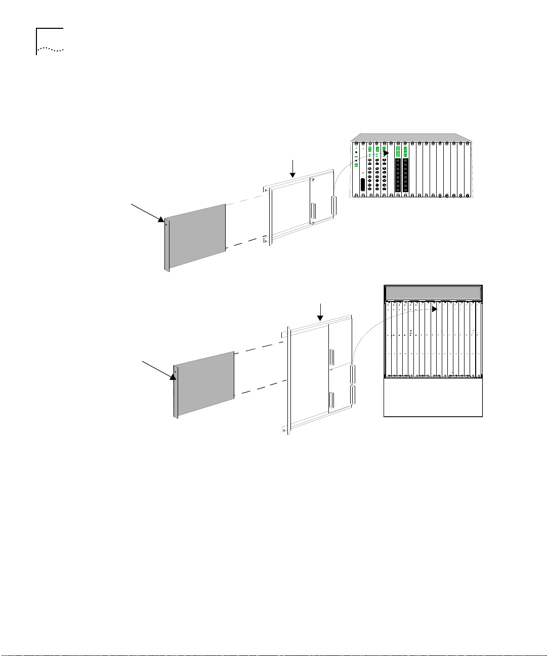
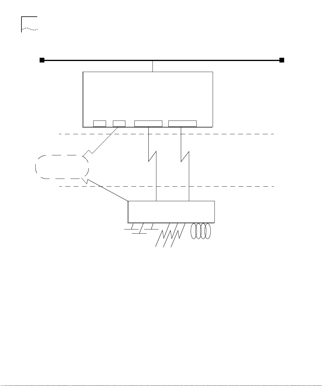
1
Install the mini-DIN to DB-25 adapter cable into the circular connector
labeled “console” or “auxiliary” on the Edge Router modu le. Figure 3-1 shows
an example of how to connect the cable to the console port.
Page 50

3-10
C
HAPTE
R
3:
C
ONFIGURIN
G THE EDGE ROUTER MODULE
Figure 3-1
2
Attach the DB-25 end of the adapter cable to the RS-232 null modem ca ble
Attaching a Terminal Cable to the Console Port
coming from your term inal. Figure 3-2 shows the terminal connecti ons to
both the manageme nt module and the Edge Router conso le port.
• Configure LAN Access module
Configure the Edge Router engine
Assign Edge Router module to network and
report module status
• Configure module to network
• Report module status
Figure 3-2
Terminal Connections
Page 51

Configuring the Edge Router Engine
Console and auxiliar y por t speci fications are provided in Table3- 2 and
Table 3 -3, respec tively.
3-11
Table3-2
Interface
RS-232
Table3-3
Interface
RS-232
Console Port Informati on
Transmis sion
Connector
8-pin mini-DI N
Auxiliar y Port Info rmation
Connector
8-pin mini-DI N
Type
DTE
Transmis sion
Type
DTE
Protoco l
Asynchronous, 9600, 8-bit data,
1 stop bit, no par ity, XON /XOFF
Protoco l
Asynchronou s or syn chronous , 9600,
8-bit data, 1 stop bit, no parity,
XON/XOFF
Mini-DIN connector pinouts are provided in Appendix A.
The Edge Router module is shipped autoconfi gured for con nection to a
network running NetWare®. If you are not connected to a NetWare network,
you may see the following message:
The IPX Network for LocalPath ms_etherne t couldn’t be
learne d.
Using the Terminal
to Configure the
Edge Route r Engine
Ignore this mes sage and continue with the appropria te configurati on.
Edge Router engine documentatio n is included on the Cisco Systems
CD-ROM th at is shipped w ith the Edge Ro uter modu le.
Refer to the
Cisco Router Products Confi guration an d Referenc e Guide
for
information on configuring pa rameters for the Edge Rou ter module.
Page 52

Page 53

4
M
ONITORING
M
ODULE
This chapter co ntains the following section s:
■
Monitorin g Ed ge Ro uter Mod ule Ope ration
■
Showing M odule Config uration and Status
O
E
DGE
PERATIO
R
OUTER
N
Monitoring Edge Router Module Operatio n
The LEDs on the front panel of the Edge Router module allow you to
monitor the statu s of the modul e and por ts. When you install the Edge
Router
1
The Router Status (RTR ) LED is off if the router is booting (initia lizing).
2
The Router Status (RTR ) LED illuminates once the router boot software is
running.
3
The Module Status (S) LED bl inks while the module is attempti ng
communi cation with th e carrier board.
4
The Module Statu s (S) LED stays illumi nated once com munication is
established with the carr ier board.
Figure4-1 shows the LED locations. Each LED indicates the state of the
module or port as described in Table4-1.
module
in th e h ub:
Page 54

4-2
C
HAPTE
R
4:
M
ONITORING EDGE ROUTER MODULE OPERATIO
N
Router Status
Figure 4-1
Edge Router Module LEDs
RTR
Reset
EO
CONSOLE
AUX
S0
ACT
S1
ACT
2103R-CS
S
Module Status
Ethernet
Activity
Reset
Pushbutton
Serial Port 0
Activity
Serial Port 1
Activity
Page 55

Showing Module Configuration and Status
Each LED is described in Table4-1.
4-3
Table4-1
LED Name
S
(Module Sta tus)
RTR
(Router Status )
E0 Activ ity
(Ethernet Activ ity)
S0
(Serial Po rt 0 A ctivity)
S1
(Serial Po rt 1 A ctivity)
Module LED I nterpreta tions
Color
Gree n
Gree n
Yellow
Yellow
Yellow
Stat e
Blinkin g
On
On
Off or Bl inking
Blinkin g
Blinkin g
Blinkin g
Indicates
The module is in boot mode
and is atte mpting
communicati on with the
carrier bo ard .
Remain s lit as long as ther e
is active comm unica tion
with the carrier boar d.
Router is fu nctioning
properly.
Router is not fun ctioni ng.
Replace th e module .
Traffic is bei ng p assed .
Traffic is bei ng p assed on
serial por t 0.
Traffic is bei ng p assed on
serial por t 1.
Showing Module
Configuration
and Status
This section describe s NMM comm ands that show module con figurati on
and status.
To show configur ation and status for an Edge R outer m odule, use the
following n etwork m anagem ent modu le comman ds:
■
SHOW MODULE
■
SHO W POR T
Page 56

4-4
C
HAPTE
R
4:
M
ONITORING EDGE ROUTER MODULE OPERATIO
N
Using th e SHOW
MODULE Command
The SHOW MO DULE comm and display s informa tion about a speci fic
module.
The syntax for th e SHOW MOD ULE comm and is:
SHOW MODULE
slot
{verbos e}
{no_ver bo se}
The following com mand displ ays verbose infor mation for an Edge Rou ter
module ins talled in slo t1 of an ONcore hub:
ONcore > s how module 1. 1 verbose
Slot Mo dule Ve rsion Netw ork Genera l Informat ion
----- --------- ------- ------- ----------------
01.01 6 102M-SDEK v1.00 PER_PORT 2 103R-CSDI
6102M- SDEK: ONco re ONdeck Ethernet Ca rrier Modu le
Boot Ve rsion: v1.00
ENGINE 1 Model Nu mber: 2103R- CSDI
Descri ption: Edge Rt r DIBMSW
Expans ion Module Model N umber:
Native Software V ersion: v10.03
Native Boot Softw are Version : v4.14
IP Defa ult Gatewa y: 0.0.0. 0
Mailbox Version: 0.00.0
No. Bac kplane Ports : 1
No. Fro nt Ports: 2
Engine Status: OK AY
NVRAM D ip Switch St ate: DISABL ED
Module Capabilit ies: MACCFG ;IPCFG;
ENGINE 2 Model Nu mber: NOT INS TALLED
Descri ption:
Expans ion Module Model N umber:
Native Software Version:
Native Boot Softw are Version :
IP Defa ult Gatewa y: 0.0.0. 0
Mailbox Version: 0.00.0
No. Bac kplane Ports : 4
No. Fro nt Ports: 0
Engine Status: NOT INS TALLED
NVRAM D ip Switch St ate: DISABL ED
Module Capabilit ies: -NONE-
Page 57

Showing Module Configuration and Status
4-5
The following comm and displays verbo se informatio n for an Edge Router
module ins talled in s lot 6 of an ONli ne hub:
ONline> show module 6 verbose
Slot Module Version Network General Information
----- --------- ------ ------- ------------06 2103R-CSD v1.07 PER_PORT Port(s) are up
5103R-CSD: Ethernet Edge Rtr DeskSW
Module Capabilities: MACCFG;IPCFG;
No. Front Panel Ports: 2
Boot Version: v1.01
Native Software Version: x10.00
Native Boot Software Version: x51.30
No_Verbose is the d efa ult op tion fo r the S HOW MODULE c om m an d. Use the
No_Verbose optio n to displ ay summar y inform ation for the carr ier. The
following com mand displays su mmar y informa tion for an Edge Rou ter
module ins talled in slo t1 of an ONcore hub:
ONcore> show module 1.1
Slot Module Version Network General Information
----- --------- ------ ------- -------------
01.01 6102M-SDEK v1.00 PER_PORT 2103R-CSDI
Page 58

4-6
C
HAPTE
R
4:
M
ONITORING EDGE ROUTER MODULE OPERATIO
N
Using th e SHOW
PORT Command
The
SHOW PORT
command displays information about a single port or all
ports.
The syntax for th e
SHOW PORT
SHOW PORT
slot.port
comman d is:
{verbo se}
{no_ve rb ose}
The following com mand d isplays verbose informatio n for por t 1 on an
Edge Router module installed in slot 1 of an ONcore hub:
ONcore> show port 1.1 verbose
Port Display for Module 6102M-SDEK:
Port Mode Status Network General Information
----- ------ ------- ------- ----------- -----
01.01 LOGICAL OKAY ETHERNET_4 2103R-CSDI
Port Connect or: BACKPLANE
IP Address: 2.0.0.2
Subnetwork Mask: ff.00.00.00
Station Address: 00-00-0c-c0-3d-63
Dip Network Setting: ETHERNET_4
The following com mand d isplays verbose informatio n for por t 1 on an
Edge Router modul e installed in slot 4 of an ONline hub:
ONline> show port 4.1 verbose
Port Display for Module 5103R-CSD:
Port Mode Status Network General Information
----- -------- ------ -------- ----------------
04.01 LOGICAL OKAY ETHERNET_1
Port Connect or: BACKPLANE
IP Address: 151.104.15.39
Station Address:
Capabilities: -NONENative Port Number: 0
Page 59

Showing Module Configuration and Status
4-7
No_Verbose is the default o ption for the
SHOW POR T
comman d. Use th e
No_Verbose option to dis pl ay s um m ary infor m ation for th e carrier ports. The
following com mand displays su mmar y informa tion for po rt 1 on an Edge
Router modu le installed in slo t 1 of an ONcore hu b:
ONcore > show port 1.1
Port Di splay for Mo dule 6102M-SDEK:
Port Mode Status Netw ork Ge neral Informatio n
---- ---- ------ - ---- --- --------- --------- -
01.01 LOGICAL OKAY ETHERNET_4 2103R-CSDI
Page 60

Page 61

5
T
ROUBLESHOOTIN
This chapter provid es hardware troubleshooti ng inform ation you can us e if
the Edge Router mod ule fails to operate correctly. If after reviewing the
information in th is chapter, you cann ot correct the probl em, contact you r
3Com represen tative for fur ther assista nce.
For software-rela ted troubleshoot ing infor mation, refe r to the appropriat e
Cisco Systems manual.
This chapter co ntains the following section s:
■
Troubleshootin g Start up Problems
■
Troubleshooting Netw ork Con nectivi ty Problems
■
Troubleshootin g WAN Conn ectivit y Problems
■
Correctin g Operating Malfunc tions
G
Page 62

5-2
C
HAPTE
R
5:
T
ROUBLESHOOTIN
G
Troubleshooting Startup Problems
Troubleshooting
Router- Specific
Problems
Troubleshooting
Mailb ox Inte rf ace
Problems
This section describes how to troubles hoot star tup problem s by monitori ng
the LEDs on the Edge Router module.
This section describes:
■
Troubleshootin g Router-S pecific Proble ms
■
Troubleshootin g Mailbox Inter face Problems
■
Troubleshootin g 3Com Carrier Prob lems
When you first instal l the Edge Router mod ule in an ONline or ONcore hub
the Cisco engi ne runs a full set of hardware d iagnosti c tests. If the en gine
fails diagnos tics, the Route r (RTR) LED does not illum inate or will flas h. This
indicates a proble m with the rou ter hardware or software. Refer to the
appropriate Cis co Systems troubl eshooti ng docum entation for co rrective
action.
ONline and ONcore Edge Rou ters use a hardw are mailbox inte rface tha t
allows the Cisco en gine to com municate with the 3Com car rier board
during power up. If the 3Com mailbox doe s not establish co mmunication
with th e en gin e, the foll owin g m essag e i s re por ted to the eng ine con sole
port:
Troubleshooting
3Com Carrier
Problems
%MAILB OX-3-INITFAIL:M ailbox initializ ation failu re.
Not get ting interrupts. Mail box offline.
If you see this messa ge, contact your 3Com representative for as sistance.
Before mailbox com municatio n is initialized and es tablished betw een the
Cisco engin e and the 3Com carrier, the Module Status (S) LED on the fron t
panel of the Edge R outer mod ule blinks slow ly. If communication i s
established successfully, the Status LED illu minates and stays on solid. If the
Status LED does not light, the 3Com carrier board has malfunc tioned.
Contact your 3Com representati ve for assistance. R efer to Appendix B for
instructi ons on conta cting Technical Sup port fo r you produc t.
Page 63

Troubleshooting Network Conn ectivity Problems
5-3
Troubleshooting
Network
Connectivity
Problems
If the Edge Router module does not appear to be routing traffic properly on
the network, it may indi cate that there is no connecti on to the network.
Try perfor ming one or m ore of the followi ng troubles hooting ac tions:
■
For ONline and ONcore Edge Router modu les only, use the 3Com
managem ent interface (for exampl e, ONline manage ment modu le) to verify
that the Edge Router mod ule backpl ane port is se t to the appropriate
backplane network (channel).
■
Using the Cis co terminal inter face, verify that the following para meters are
set co rrec tly :
■
IP address
■
Subnet mas k
■
Default g ateway
■
Use the ping utility to confi rm that there is netw ork conne ctivity.
■
Use th e cisco>show interfaces ethernet 0
command to verify that
the inter face i s u p an d r unnin g. This com mand repo rts Ethernet s tatistics
that aid you in tro ubl esho oting the netw or k.
If the inter face is down, you m ay need to use the C isco confi guration ed itor
to is su e th e no shutdown
comm and. The no shutdown
command
restar ts a disab led inter face.
■
Verify that your router config uration is valid. Refer to the Cisco Systems
Troubleshooting Internetworking Systems
guide for more information.
Page 64

5-4
C
HAPTE
R
5:
T
ROUBLESHOOTIN
G
Troubleshooting WAN Connectivity Problems
If you suspect that the Edge R outer module has lost WAN connectivity,
perfor m one or mo re of the followin g troubles hooting ac tions:
■
Verify that you have the correc t cable for your config uration. Re fer to
Appendix A, Spec ification s, for a list of approved cables, cabl e
specific ations, and pinou ts.
■
If you a re us ing a:
■
DCE cabl e
— Verify that a c lock rate is defi ned in the rou ter WAN
interfa ce configuratio n.
■
DTE cable
— Verify that no clock rate i s defined in the router WAN
interfa ce configuratio n.
■
Verify that the cable’s 60-pin WAN connector is not plugged in backwards.
■
Ensure that th e router configur ation does not have a SHUTD OWN com ma nd
associ ated w ith the inter fac e.
■
Verify that your router config uration is valid. Refer to the Cisco Systems
Troubleshooting Internetworking Systems
guide for more in formati on.
Page 65

Correcting Operating Ma lfunctions
5-5
Correcting
Operatin g
Malfunctions
Table 5 -1 lists the symptom s of operatin g malfunc tions for the Ed ge Router
module an d shows possible caus es an d correc tive action s for these
malfuncti ons.
Table5-1
Symptom
Module d oes not pow er
on.
Attache d termi nal does
not operate.
Troubleshooting Malfunc tions
Possible Cause
Module is no t fitted
correctly against
backplane .
The hub is receiving
no electr ical powe r.
The termina l is
malfunction ing.
Cables are
unattache d.
Cables are n ot the
correct type.
The console or
auxiliar y po rt is
configur ed
incorre ctly.
Corrective Action
Remove the mod ule f rom the slot
and replace it i n the s lot to ensure
that the mod ule is fi tted c orrectly.
Place the module in a different slot
in the hu b.
Check tha t the hub is receivin g
power.
Test for power at the wall outle t by
plugging in a nother devi ce.
Select anothe r outlet on a different
circuit if ne cessar y.
Follow the tr oubleshootin g
procedu res reco mmend ed by the
terminal manufa cture r.
Make sure that the cable
connection s at both ends are secure.
Make sur e th at th e cable atta ch ed to
the termi nal confo rms to the
specific ation as desc ribed in
Appendix A.
Check the con sole por t and aux iliar y
port configu ration s.
You can make a TELNET connecti on
to the router to verify por t
configuration s.
Refer to the Cisco Rou te r Prod ucts
Configurat ion a nd Refe re nce
documentatio n for m ore
information. Verify that the port is
configure d as 8 -bit data, no par ity,
1stop bit, 9600 baud rate, with flow
control par ameter s set to Xon and
Xoff.
Page 66

5-6
C
HAPTE
R
5:
T
ROUBLESHOOTIN
G
Table5-1
Troubleshooting Malfunc tions
Symptom
The terminal fails to
respond to commands
entered a t the k eyboard.
(continued)
Possible Cause
The termina l is n ot
receivi ng co mman ds.
The keyboard cable
is attached
incorre ctly.
The console port is
malfunction ing.
Corrective Action
Power o ff the te rmina l, wai t
30 seconds, a nd th en po wer i t on
again.
If the termin al stil l does not respond
to commands, power off the
terminal an d disc onnect the
keyboard cabl e. Then reatta ch the
keyboard cable and power on the
terminal .
Check the state of the LEDs on the
front of th e mo dule a s show n in
Table4-1. If th e LEDs indicate a
problem, contact yo ur supplier for
assista nce.
Page 67

A
S
PECIFICATIONS
This appendix con tains the hardw are specificatio ns for the 3Com Edge
Router modu le in the followi ng secti ons:
■
General Speci fications
■
Electrical Spec ifications
■
Environmen tal Specificati ons
■
Mechan ical Specificati ons
■
Hub Capaci ties
■
Cable Pinouts
Page 68

A-2
A
PPENDIX
General Specifications
A:
S
PECIFICATIONS
Electrical Specifications
TableA-1
Proces sor
Memory
Network Interface
Options
Ethernet Inte rface
Synchronous Ser ial
Interfac es
Console and Auxiliary
Ports
General Spec ifications
20 MHz Motor ola® 68EC030
4 MB DR AM (ex pandable t o 16 M B)
4 MB system code (PROM or Flash) (expandable to 8 MB)
32 KB non-vo latile configur ation R AM
1 Ethernet and 2 sync hronous se rial
Backplane c onnection
RS-232, RS-449, V.35, X.21 (NRZ/NRZI and DTE/DCE),
EIA-530 (NR Z/NRZI and DTE). All se rial ca bles us e a DB- 60
connector .
Asynch ronous serial (min i-DIN)
The following tabl e lists the basic powe r requirements by module type.
TableA-2
Module Type
ONlin e
ONcor e
*
ONcore power requirements are based on an Edge Route r engine insta lled in
bay 1 of the O Ncore car rier. Bay 2 is emp ty.
Power Require ments b y Mod ule Type
Power Re quireme nts (AMP s)
Voltage
+5
+12
-12
*
+5
+12
-12
Carrier
.40
0
0
.60
0
0
Engine
2.60
0.21
0.21
2.60
0.21
0.21
Carrier an d Engine
3.00
.21
.21
3.20
.21
.21
Page 69

Environmental Specifications
TableA-3
Environmenta l Specific ations
Environmental Spec ifications
A-3
Mechanical Specifications
Operating Tempera ture
Storage Temperatu re
Humidity
0° to 50° C (32° to 122° F)
-10° to 66° C (22° to 138° F)
Less than 95%, non con densing
Table A- 4 lists the BTU /hr calculati ons for the Edge Router mod ule installe d
in each hub ty pe.
TableA-4
Hub Type
ONlin e
ONcor e
TableA-5
Hub Type
ONlin e
ONcor e
BTU/hr Calculations
Mechanic al Specifi cations
Dimensions
Width
Length
Height
Weigh t
Width
Length
Height
Weigh t
BTU/hr
68.28
68.28
1.0”
10.275”
8.5”
1.5 lbs
1.0”
10.275”
14.37”
2.0 lbs
Page 70

A-4
A
PPENDIX
A:
S
PECIFICATIONS
Hub Capacities
ONline Hub
Capacities
ONcore Hub
Capacities
This sec tion provides guideli nes for instal ling Edg e Router mod ules in
ONline or ONc ore hubs.
Follow the guidelines in TableA-6 when installing ONline Edge Router
modules in an ONline System Concentrator.
.
TableA-6
ONline Syste m
Concentra tor
17-Slot
Concentrator
6-Slot
Concentrator
ONline M odul e Restri ction s
Model
Numbers
5017C
5006C
and
5006C-FT
Power
(Watts)
325
200
Maximum N umber
of Modu les (bo th
serial ports in use)
5
3
Maximum N umber
of Modules (one
serial port in use)
10
6
Follow the guidelines in TableA-7 when installing ONco re Edge Router
modules in an ONc ore 10-slo t or 17-s lot hub.
TableA-7
Number
of Power
Supplies
1
2
3
4
ONcore Hu b Capac iti es for ONcore Modu les
Slots
per Hub
10-Slot
17-Slot
10-Slot
17-Slot
10-Slot
17-Slot
10-Slot
17-Slot
Maximum N umber of Modu les
(fault-to leran t mode)
N/A
N/A
8
8
9
14
N/A
16
Maximum N umber of
Modules
(non-fau lt-toler ant mode )
8
8
9
14
9
16
N/A
16
Page 71

Cable Pinouts
Follow the guidelines in TableA-8 when installing ONline Edge Router
modules in an ONcore 1 0-slot o r 17-slot hub.
.
TableA-8
ONcore Hu b Capac iti es for ONline Mod ules
A-5
Cable Pinouts
Number
of Power
Supplies
1
1
2
3
4
1
If hub is se t t o f au lt- tole ran t mod e, a pp ly restrictions fo r 1 po wer su p pl y.
Slots per
Hub
10-Slot
17-Slot
10-Slot
17-Slot
10-Slot
17-Slot
10-Slot
17-Slot
Maximum Numbe r of
Modules (both ser ial
ports in use)
7
10
14
10
17
10
17
Maximum Numbe r of
Modules (one ser ial
port in use)
10
14
10
17
10
17
10
17
Use the informa tion in this sec tion to en sure that the cabl es an d connec ting
hardware m eet requireme nts. For proper operati on, use only app roved
cables whe n you ins tall all equ ipment.
The conso le and au xiliar y por ts on the Edg e Router modul e require a
mini-DIN to DB-2 5 serial por t adap ter cable. You can use a cable that meets
the specificati ons describ ed in this sec tion or you can pu rchase the 3Com
OpenHub Man agement Cabl e (Part Number OHPMG T-CAB).
The OpenHub Management Cable has a:
■
Mini-DIN conne ctor
— Plugs into th e consol e or aux iliar y por t on the Edg e
Router modu le.
■
DB-25 c onnect or
— Plugs into the cable of the per ipheral de vice.
To connect the mini-DIN to DB-25 cable to another DTE device, use a null
modem ad apter.
Page 72

A-6
A
PPENDIX
A:
S
PECIFICATIONS
This section describes:
■
Console Port Pi nouts
■
Auxili ar y Port Pi nout s
■
DB-25 Nul l Modem Ca ble
■
Serial Port Pinouts
Console Port
Pino uts
This section lists the cabl e pinouts for the:
■
DTE co nso le po rt
■
Mini-DIN to DB-25 modem cable
DTE Cons ole Por t
Table A- 9 lists pinou ts for the console por t on the Edge R outer module.
TableA-9
Pin
1
2
3
4
5
6
7
8
Console Port Pinou ts (DTE)
Signal
DTR
Input/Output
Output
Not Connected
TXD
Output
GND
RXD
Input
Not Connected
DCD
Input
Not Connected
Page 73

Cable Pinouts
FigureA-1 identifi es the pin s that the 8-pin m ini-DIN por t uses.
678
34 5
12
A-7
FigureA-1
Mini-DIN Se rial Port Pinouts
Mini-D IN to DB-25 Mo dem Cable
Table A- 10 lists con sole por t pinouts for the 3Com OpenHub™ Manage ment
Cable (min i-DIN to DB-25 mo dem adapter ca ble).
TableA-10
Mini-DIN
Pin
1
2
3
4
5
6
7
8
Console Port Pin outs (Mi ni-DIN to DB-25 M odem Cable )
DB-25
Signal
DTR
Not Connected
TXD
GND
RXD
Not Connected
DCD
Not Connected
Pin
20
5
2
7
3
4
8
17
Signal
DTR
CTS
TXD
GND
RXD
RTS
DCD
RTXC
Input/Outpu t
Output
Output
Inpu t
Inpu t
Page 74

A-8
A
PPENDIX
A:
S
PECIFICATIONS
Auxiliar y Port
Pino uts
Table A- 11 lists the cab le pinouts for th e auxiliar y port on the Edge Router
module.
TableA-11
Pin
1
2
3
4
5
6
7
8
Auxiliar y Por t Pi nouts (DTE)
Signal
DTR
CTS
TXD
GND
RXD
RTS
DCD
Not Connected
Input/Output
Output
Input
Output
Input
Output
Input
Mini-D IN to DB-25 Mo dem Cable
Table A- 12 lists auxi liary port pinouts for the 3Com OpenHub Man agemen t
Cable (min i-DIN to DB-25 mo dem adapter ca ble).
TableA-12
Auxiliar y Port Pi nouts ( Mini-DI N to DB-2 5 Mode m Cable)
Mini-DIN
Pin
1
2
3
4
5
6
7
8
Signal
DTR
CTS
TXD
GND
RXD
RTS
DCD
Not Connecte d
DB-25
Pin
20
5
2
7
3
4
8
17
Signal
DTR
CTS
TXD
GND
RXD
RTS
DCD
RTXC
Input/O utput
Output
Input
Output
Input
Output
Input
Page 75

Cable Pinouts
A-9
DB-25 Null Modem
Cable
Serial Port Pinou ts
Use a null m od e m ca ble to connect the Edge R outer modu le to an other DTE
device (for exam ple, a dumb term inal).
This section lists ca ble pinouts for each type of synch ronous serial cabl e
supported by the serial por ts on the Edg e Router mod ule.
This section describes:
■
EIA-530 DTE Sync hronou s Seri al Cabl e Pinout s
■
RS-232 DT E and DCE S erial Cabl e Pinouts
■
RS-449 DT E and DCE S erial Cabl e Pinouts
■
V.35 DTE and DCE Serial Cable Pinouts
■
X.21 DTE and DCE Seria l Cable Pin outs
In the followi ng tables, ser ial pinouts for DTE and DCE cabl es use arrow s to
indica te s ignal dire c tion :
■ →
indicates DTE to DCE
■ ←
indi cate s DC E to D TE
All serial cables have a DB-60 connector on the module end. The following
pinouts repr esent only the mo dule ends of the cables. D ue to the smal l pins
on the D B-60 conne ctor, you sho uld n ot attem pt t o man ufact ure or solde r
these cables.
Page 76

A-10
A
PPENDIX
A:
S
PECIFICATIONS
EIA-530 DT E Synchron ous S erial Cab le Pino uts
Table A- 13 lists pinouts for E IA-530 DTE synchron ous seri al cable
(Part Nu mber ERM5 30-CAB).
TableA-13
25 Pin
J2-1
—
J2-2
J2-14
J2-3
J2-16
J2-4
J2-19
J2-5
J2-13
J2-6
J2-22
1
Any pin not referenced is not co nnected.
2
The EIA-5 30 interface can n ot be o perat e d in DCE mode. A DCE cable is not available for th e EIA-530 interface.
EIA-530 DTE Cable Pinouts (DB-25)
1
Signal
Shield
—
BA(A), TxD+
BA(B) , Tx D-
BB(A), RxD+
BB(B), RxD-
CA(A), RTS+
CA(B), RTS-
CB(A), CTS+
CB(B), CTS-
CC(A), D SR+
CC(B), DSR-
Direction
DTE DCE225 Pin
—
—
→
→
←
←
→
→
←
←
←
←
J2-8
J2-10
J2-15
J2-12
J2-17
J2-9
J2-18
J2-7
J2-20
J2-23
J2-24
J2-11
Signal
CF(A), DCD+
CF(B), DCD-
DB(A), TxC+
DB(B), TxC-
DD(A), RxC+
DD(B), RxC-
LL
Circuit GND
CD(A), DTR+
CD(B), DTR-
DA(A), TxCE+
DA(B), TxCE-
DTE DCE
Direction
←
←
←
←
←
←
→
—
→
→
→
→
Page 77

Cable Pinouts
RS-232 DTE and DCE Serial Cable Pinouts
Table A- 14 lists pinouts for:
■
RS-232 DTE s ynchronou s serial cable (Part Num ber ERM23 2-CAB)
■
RS-232 DCE syn chronous ser ial cable (Part Nu mber ERF232 -CAB
)
TableA-14
RS-232 DTE and DCE Cable Pinouts (DB- 25)
A-11
)
1
25 Pin
J2-1
J2-2 Shield
J2-3 Shield
J2-4 Shield
J2-5 Shield
J2-6 Shield
1
Any p in not re fe re nce d is not co n ne cte d.
Signal
Shield GND
TxD
—
RxD
—
RTS
—
CTS
—
DSR
—
DTE DCE
Direction
—
→
—
←
—
→
—
←
—
←
—
25 Pin
J2-7
Shield
J2-8
Shield
J2-15
Shield
J2-17
Shield
J2-18
Shield
J2-20
Shield
J2-24
Shield
DTE DCE
Signal
Circuit GND——
DCD
—
TxC
—
RxC
—
LTST
—
DTR
—
TxCE
—
Direction
—
←
—
←
—
←
—
→
—
→
—
→
—
Page 78

A-12
A
PPENDIX
A:
S
PECIFICATIONS
RS-449 DTE and DCE Serial Cable Pinouts
Table A- 15 lists pinouts for:
■
RS-449 DTE s ynchronou s serial cable (Part Num ber ERM44 9-CAB)
■
RS-449 DCE syn chronous ser ial cable (Part Nu mber ERF449 -CAB
)
TableA-15
37 Pin
J2-1
J2-4
J2-22
J2-5
J2-23
J2-6
J2-24
J2-7
J2-25
J2-8
J2-26
1
Any pin not ref eren ce d is n ot con necte d.
RS-449 DTE and DCE Cable Pinouts (DB- 37)
1
Signal
Shield GND
SD+
SD-
ST+
ST-
RD+
RD-
RS+
RS-
RT+
RT-
DTE DCE
Direction
—
←
←
→
→
→
→
←
←
→
→
37 Pin
J2-9
J2-27
J2-10
J2-37
J2-11
J2-29
J2-12
J2-30
J2-13
J2-31
J2-17
J2-35
J2-19
J2-20
Signal
CS+
CS-
LL
SC
DM+
DM-
TR+
TR-
RR+
RR-
TT+
TT-
SG
RC
DTE DCE
Direction
→
→
→
—
→
→
←
←
→
→
←
←
—
—
Page 79

V.35 DTE and DCE Serial Cable Pinouts
Table A- 16 lists pinouts for:
■
V.35 DTE synchron ous seri al cable (Pa rt Numb er ERMV3 5-CAB )
■
V.35 DCE synchron ous seri al cable (Pa rt Numbe r ERFV3 5-CAB)
Cable Pinouts
A-13
TableA-16
34 Pin
J2-A
J2-B
Shield
J2-C
Shield
J2-D
Shield
J2-E
Shield
J2-F
Shield
1
Any pin not re feren c ed i s not con n ecte d.
V.35 DTE and DCE Ca ble Pinouts
1
Signal
Fram e GN D
Circuit GND
—
RTS
—
CTS
—
DSR
—
RLSD
—
DTE DCE
Direction
—
—
—
→
—
←
—
←
—
←
—
(W inchester -Type 34-Pin)
34 Pin
J2-H
Shield
J2-K
Shield
J2-P
J2-S
J2-R
J2-T
J2-U
J2-W
J2-V
J2-X
J2-Y
J2-AA
Signal
DTR
—
LT
—
SD+
SD-
RD+
RD-
SCTE+
SCTE-
SCR+
SCR-
SCT+
SCT-
DTE DCE
Direction
→
—
→
—
→
→
←
←
→
→
←
←
←
←
Page 80

A-14
A
PPENDIX
A:
S
PECIFICATIONS
X.21 DTE an d DCE Serial Cable Pin outs
Table A- 17 lists pinouts for:
■
X.21 DTE s ynchron ous seri al cable (Par t Numbe r ERMX2 1-CAB)
■
X-21 DCE syn chronou s serial cable (Part Number ERF X21-CAB )
TableA-17
15 Pin
J2-1
J2-2
J2-9
J2-3
J2-10
J2-4
J2-11
J2-5
J2-12
J2-6
J2-13
J2-8
Shield
1
Any pin not ref eren ced is n ot con n ecte d.
X.21 DTE and DCE Cable Pinouts (DB-15)
1
Signal
Shield GND
Transmit+
Transmit-
Control+
Control-
Receive+
Receive-
Indication+
Indication-
Timing+
Timing-
Circuit GND
—
DTE DCE
Direction
—
→
→
→
→
←
←
←
←
←
←
—
—
Page 81

B
T
ECHNICA
3Com provide s easy access to technical supp ort info rmation through a
variety of s er vices. T his a ppen dix c ontain s th e fol lowi ng s ectio ns:
■
Online Technical Se r vice s
■
Support From Your Network Supplier
■
Support From 3Com Corpor ation
■
Returnin g Products for R epair
■
Accessing the 3Com ISD MIB
■
Contac ting 3Com IS D Technical Publ ications
L
S
UPPOR
T
Online Technical
Services
3Com Bulle tin
Board S ervice
3Com offers world wide produc t support 7 day s a week, 24 hours a day,
through the fol lowing onl ine systems:
■
3Com Bulletin Board Service (3ComBBS)
■
World Wide Web site
■
3ComForum on Co mpuSer ve®
■
3Com FactsSM automated fax se rv ice
3ComBBS con tains p atches, sof twa re, and d rivers for all 3Co m pr oduc ts, as
well as technical ar ticles. This ser vice is availabl e through a mod em or ISDN
7 days a week, 24 hour s a day.
Page 82

B-2
A
PPENDIX
B:
T
ECHNICA
L SUPPOR
T
Access by Ana log Mo dem
To reach the service by modem, set you r modem to 8 data bits, n o parity,
and 1 stop bit. Call the teleph one num ber neares t you:
Coun tr y
Australia
Data Rate
up to 14400 bps
Telephone Number
Sydney (61) (2) 9937 5000
Melbourne ( 61) (3) 9 653 9515
France
Germany
Hong Kong
Ital y (f ee re qui re d)
Japan
Singapore
Taiwan
U.K.
U.S.
up to 14400 bps
up to 9600 bps
up to 14400 bps
up to 14400 bps
up to 14400 bps
up to 14400 bps
up to 14400 bps
up to 28800 bps
up to 28800 bps
(33) (1) 6 9 86 69 5 4
(49) (89) 627 3 2 18 8 or (49) (89) 627 32 189
(852) 2501 1111
(39) (2) 2 73 00680
(81) (3) 3 345 7266
(65) 534 5693
(886) (2) 377 5840
(44) (1442) 278278
(1) (408) 980 8204
Access by Dig ital Mod em
ISDN users can cal l in to 3ComBBS using a digital modem fo r fast access up
to 56 Kbps. To access 3ComBBS usi ng ISDN, call th e following n umber:
(408) 65 4-27 03
Page 83

Online Technical Services
B-3
World Wid e Web Site
3ComForum on
CompuServe
3ComFacts Automated
Fax Service
Access the lates t net work ing i nform ation on th e 3Com World W ide Web site
by entering ou r URL into your Intern et browser :
http://www.3Com.com/
This serv ice features news an d inform ation about 3Com prod ucts, cus tomer
serv ice and suppor t, 3Com Corpor ation’s latest new s releases, sele cted
articl es from 3 TECH™ (3Com Corpo rati on’s award -wi nning tec hnical
journal), an d more.
3ComForum is a Com puSer ve-base d service con tainin g patches, software,
drivers, and tech nical ar ticles a bout all 3Com produ cts, as well as a
messaging secti on for peer suppor t. To use 3ComForum, you need a
CompuS erve account.
To use 3ComForum:
1
Log in to Co mpuS e rve.
2
Ente r go threecom
3
Press Return to view the 3ComForum main menu.
.
3Com Corporati on’s interac tive fax ser vice, 3ComFacts, provi des data sh eets,
technical arti cles, di agrams, and trou blesho oting instruc tions on 3Com
products 7 days a week, 24 hour s a day.
Call 3ComFacts using your touc h-tone telephon e. Internationa l access
numbers are :
Country
Hong Kong
U.K.
U.S.
Telephon e N um ber
(852) 2537 5610
(44) (1442) 278279
(1) (408) 727 7021
Page 84

B-4
A
PPENDIX
B:
T
ECHNICA
L SUPPOR
T
Local access numbers are available within the following countries:
Suppor t From Your Network Supplier
Country
Australia
Belgium
Denmark
Finlan d
France
Germany
Italy
Telephone Number
800 123853
0800 71279
800 17319
98 001 4444
05 90 81 58
0130 8180 63
1678 99085
Country
Netherland s
Norway
Portugal
Russia (Moscow only)
Spain
Sweden
U.K.
Telephon e N um ber
06 0228049
800 11062
0505 442607
956 0815
900 964445
020 792954
0800 626403
If addition al assistance i s required, contact yo ur networ k supplier. Many
suppliers are autho rize d 3Com ser vice pa rt ners wh o are q uali fied to provi de
a variety of ser vices, i ncludin g network pl anning, instal lation, hardware
maintenance, applicati on training, and suppo rt ser vices.
When you co ntact you r ne twork sup plier fo r ass istan ce, have th e fol lowin g
informatio n ready:
■
Diagno stic error messag es
■
A list of system hardware and softw are, includi ng revisio n levels
■
Details abou t re cent confi gurati on c ha nges, if appl icabl e
If you are unabl e to contact your n etwork su pplier, refer to the following
section on contacting 3Com.
Page 85

Support From 3Com Corporation
B-5
Suppor t From
3Com
Corporation
If you are unabl e to receive suppor t from your ne twork sup plier, technical
support con tracts are available from 3Com.
In the U.S. and Canada, call
(800) 876-3266
for custom er ser vice.
If you are outside the U.S. and Canada, contact your loca l 3Com sales office
to find your au thori zed s er vice provi der :
Country
Austral ia (Sydney)
(Melbourne)
Belgium
*
Brazil
Canad a
Denmark
Finlan d
France
Germany
*
*
*
*
Hong Kong
*
Irelan d
*
Italy
Telephone
Numbe r
(61) (2) 9937 5000
(61) (3) 9653 9515
0800 71429
(55) (11) 546 0869
(905) 882 9964
800 17309
0800 113153
05 917959
0130 821502
(852) 2501 1111
1 800 553117
1678 79489
Country
Japan
Mexico
Netherland s
Norway
*
*
Singapore
South Africa
*
Spain
*
Sweden
Taiwan
United Arab Emirates
*
U.K.
U.S.
Telephone
Numbe r
(81) (3) 3 345 7251
(525) 531 0591
06 0227788
800 13376
(65) 538 9368
(27) (11) 8 03 7404
900 983125
120 795482
(886) (2) 577 4352
(971) (4) 349049
0800 966197
(1) (408) 492 1790
Returning Products for Repair
*
These numbers are tol l-free.
A product se nt direc tly to 3Com for repai r must first be a ssigned a Retur n
Materials Autho rization (RMA) number. A product sent to 3Com w ithout an
RMA number w ill be returned to the sender un opened, at the sende r’s
expense.
To obtain an R MA number, call or fax:
Country
U.S. and Canada
Europe
Outside E urope , U.S., an d Canad a
Telephone Numbe r
(800) 876 3266, option 2
31 30 60 29900, option 5
(1) (408) 492 1790
Fax Number
(408) 764 7120
(44) (1442) 275822
(1) (408) 764 7290
Page 86

B-6
A
PPENDIX
B:
T
ECHNICA
L SUPPOR
T
Accessing the 3Com ISD MIB
The 3Com Mana gement Informati on Base (MIB ) for the Integrated System s
Division (ISD) desc ribes comman ds that enable you to manage 3 Com
SNMP-ba sed products. T he MIB is availabl e over the Internet on an
anonym ous FTP s erver. Updates to th ese MIB s are releas ed as ne w 3Com
products are introdu ced.
To access Internet versi ons:
1
FTP to ftp.chipcom.com
2
Enter the login name
3
Enter your full Internet e-mail address as the password
(for exam ple, jdoe@company.com
4
Change to the mib or schema directory using the cd /pub/mibs
cd /pub/mibs/schemas
5
To view the 3Com MIB, OID, or schem a entries, enter the dir comm and.
■
To pause th e display, press [Ctrl+ S].
■
To contin ue the displ ay, press [Ctrl+Q].
6
Copy the MIB, OI D, or schema files to your current dire ctor y using the
appropriate com mand (for example, get chipcom.mib
(151.104.9.65).
anonymou s
comm and.
.
).
or
).
Contacting 3Com ISD Technical Publications
7
To exi t the FTP s ession , invoke th e quit
comman d.
If you h ave c ommen ts or q ues tions o n 3Com Integrated Sy stems Di visi on
Techni cal Publica tions docum ents, contac t the Technical Publicatio ns
group by fax at (508) 229-1551.
Page 87

I
NDE
X
Numerics
3Com Bulletin Boa rd Ser v ice (3ComBBS)
3Com sales offices
3ComFacts
3ComForum
B-5
B-3
B-3
A
Audience of Manua l
Auxiliary port
pinouts
specifications
troubleshooting
9
A-8
3-11
5-5
B
Backplane
Bulletin board serv ice
2-13
B-1
B-1
Configuration
attaching termin al
managed h ub over view
managed ONcore carrier
managed ONline car rier
management a gents
NVRAM settings
ONcore carrier de fault s etting s
ONcore carrier DIP switches
ONcore DM M setting s
ONcore sources
ONline carrier DIP switches
unma nage d O Ncor e hu b
unma nage d O Nlin e h ub
Console port
specifications
troublesho oting
conventions
text, About This Guide
3-9
3-3
2-10,
3-5
3-11
5-5
3-2
3-6
3-5
10
3-2
3-5to
3-4
2-9to
2-8
2-10
2-9
3-9
3-6
2-11
I
NDE
X
1
C
Cable pinouts
console port
EIA-530 DTE cable
RS-232 DTE/DCE cable
RS-449 DTE/DCE cable
serial port
V.35 DTE/DCE cable
X.21 DTE/DCE cable
Carrier configuration
mana ged O Nco re hu b
mana ged O Nlin e h ub
ONcore NVRAM settings
ONline DIP switches
unmanaged O Nco re hub
unmanaged ONline hub
Carrier problems
troubleshooting
Commands
SHOW MODULE
SHOW PORT
CompuServe
A-6to
A-9 to
4-6
B-3
A-14
5-2
4-4
A-7
A-10
A-13
A-14
2-9
A-11
A-12
3-5to
3-4
2-10
2-8
2-9to
3-9
2-11
E
Edge Router module
architecture
handl ing
hardware specifications
installing
LEDs
managed hu b configuration
management a gents
network reliability
ONcore in stallat ion
ONline installation
restrictions
software options
supported protocols
topology switching
unmanaged hub config uration
EIA-530 DTE cable pinouts
Electrostatic discha rge (ESD)
precautionar y procedures
4-1,
1-3
2-3
2-12 to
4-3
A-4
2-15
1-7
2-13to
2-12to
1-5
1-7
3-2
1-5
A-2
A-10
2-15
2-13
2-3
3-2to
2-7to
3-8
2-8
Page 88

2
I
NDE
X
F
Faceplate
Fax service.
FCC notice
Firmware
Flowchart
Front panel
2-13
See
ii
upgrading
installation
LEDs
4-1
3ComFacts
1-8
2-2
H
Hardware speci fications
Hot swapping
2-13
A-1
I
Installation
flowchart
hot swapping
ONcore Edge Route r module
ONline Edge Router module
quick
quick for managed hubs
2-2
3-7
2-3
J
Jumpers
default settings
2-7
L
LED operations
LEDs
4-3
4-1
M
Mailbox inter face
troubleshooting
Managed con figurati on
management terminal conne ctions
ONcore carrier
ONline carrier
Manage d hu b
configuration
mana geme nt agen ts
quick installation
Manage ment agent s
Managemen t term inal
3-5to
3-4
3-2
5-2
3-9
3-2
2-5
3-2
2-5
2-13to
2-12to
2-15
2-13
3-3
attaching to e ngin e
attaching to m anag ement module
Memory
upgrading
MIB
B-6
Module L EDs
interpreting
Module St atus (S ) LE D
1-9
3-3
4-3
5-2
N
Network connectivit y problem s
troublesho oting
Network reliability
Network selection
ONcore carrier DIP switches
ONcore management commands
ONline carrier DIP switches
ONline management commands
Network supplier suppor t
NVRAM
NVRAM settings
2-10
enabling or d isabl ing
1-7
5-3
B-4
2-10,
2-11
2-9
3-6
O
ONcore
carrier configurati on sources
carrier default settings
carrier DIP switches
configuring in managed hub
DMM set ting s
installing the Edge Router mod ule
NVRAM settings
ONcore Multiprotocol Switching Hub
module restr ic tions
ONline
carrier DIP switches
configuring in managed hub
configuring in unmanaged hu b
installing the Edge Router mod ule
module restr ic tions
Online technical serv ices
OpenHub Management Cable
Operating malfunc tions
2-10
3-5
3-6
A-5
2-9
A-4
5-5to
3-8
3-6
3-5to
3-4
B-1
A-5
5-6
P
Power restrictions
Precautions
electrostatic discharge (ESD)
A-4
2-3
3-8
3-4
2-8
3-3
3-9
2-13to
2-12to
2-15
2-13
Page 89

I
NDE
X
3
R
Returning products for repair
Router (RTR) LE D
Router problems
troubleshooting
Router Software Support Service
RS-232 DTE/DCE cable pinouts
RS-449 DTE/DCE cable pinouts
5-2
5-2
B-5
1-8
A-11
A-12
S
SHOW MODULE command
SHOW PORT command
Simple Network Management Protocol (SNMP)
SNMP Commands
Software
update kits
Specifications
hardware
Status
show ing
B-6
1-8
A-2
4-3
4-4
4-6
T
Technical support
Topology switching
Troubleshooting
carrier problems
mailbox problems
network connect ivit y problems
operating malfunctions
router problems
startup problems
WAN connectivity problems
B-1
1-7
5-2
5-2
5-2
5-2
5-5 to
5-3
5-6
5-4
1-7
W
WAN connectivity problems
troublesho oting
5-4
X
X.21 DTE/DCE cable pinouts
A-14
U
Unmanag ed hub
ONcore carrier
ONline carrier
Unpacking
Update kits
software
Upgrading
firmware
memor y
2-9
2-8
2-6
1-8
1-8
1-9
V
V.35 DTE/DCE cable pinouts
A-13
Page 90

Page 91

LIMITED WARRANTY
HARDWARE:
3Com warrants its hardware products to be free from d efects in workmanship and m aterials, unde r normal use and service, for the
following lengths of time from the date of purchase from 3Com or its Authorized Reseller:
Internetworking products
Network adapters
1 year
Lifetime
Ethernet stackable hubs and
Unmanaged Ethernet fixed port repeaters
*Power supply and fans in these stackable hubs and unmanaged rep eaters
Other hardware products
Spare parts and spares kits
If a product does not operate as warranted above during the applicable warranty period, 3Com shall, at its option and expense, r
defective product or part, deliver to Customer an equivalent product or part to replace the defective item, or refund to Custome
price paid for the defective product. All products that are replaced will become the prope rty of 3Com. Replacement products may
reconditioned. Any replaced or repaired product or part has a ninety (90) day warranty or the remainder of the initial warranty
Lifetime* (1 year if not registered)
1 year
1 year
90 days
epair the
r the purchase
be new or
period,
whichever is long er.
3Com shall not be responsible for any software, firmware, information, or memory data of Customer containe d in, stored on, or in
tegrated with
any products returned to 3Com fo r repair, whethe r under warranty or not .
SOFTWARE: 3Com warrants that the software prog rams license d from it w ill perform in substantial con formance to the program sp ecifications
therefor for a period of ninety (90) days from the date of purchase from 3Com or its Authorized Reseller. 3Com warrants the medi
software against failure during the warranty period. No updates are provided. 3Com's sole obligation with respect to this expres
be (at 3Com's discretion) to refund the purchase price paid by Customer for any defective software products, or to replace any d
with software which substantially conforms to 3Com's applicable published specifications. Customer assumes resp onsibility for th
the appropriate applications program and associated reference materials. 3Com makes no warranty or representation that its softw
will work in combination with any hardware or applications software products provided by third parties, that the operation of th
products will be uninterrupted or error-free, or that all defects in the software products will be corrected . For any third-part
the 3Com software product documentation or specifications as being compatible, 3Com will make reasonable efforts to provide comp
a containing
s warranty shall
efective media
e selection of
are products
e software
y products listed in
atibility,
except where the non-com patibility is caused by a "bug " or defect in the third party's product.
STANDARD WARRANTY SERVICE :
accompanied by a copy of the dated proof of purchase, to 3Com's Corporate Service Center or to an Authorized 3Com Service Center
the applicable warranty period. Standard warranty service for software products may be ob tained by tele phoning 3Com's Corp o rate
Center or an Authorized 3Com Service Center, within the warranty period. Products returned to 3Com's Corporate Service Center mu
pre-authorized by 3Com with a Return Material Authorization (RMA) number marked on the outside of the package, and sent prepaid,
and packaged appropri ately for safe shipment. The repaired or replaced item will be shipped to Custome r, at 3Com's expense, n ot
Standard warranty service for hardware products may be obtained by delivering the defective product,
during
Service
st be
insured,
later than
thirty (30) days after receipt of the defective product by 3Com.
WARRANTIES EXCLUSIVE: IF A 3COM PRODUCT DOES NOT OPERATE AS WARRANTED ABOVE, CUSTOMER'S SOLE REMED Y FOR BREACH OF
THAT WARRANTY SHALL BE REPAIR, REPLACEM ENT, OR REFUND OF THE PURCHASE PRICE PAID, AT 3COM'S OPTION . TO THE FULL EXTENT
ALLOWED BY LAW, THE FOREGOING WARRANTIES AND REMEDI ES ARE EXCLUSIVE AND ARE IN LIEU OF ALL OTHER WARRANTIES , TERMS, OR
CONDITIONS, EXPR ESS OR IMPLIED , EITHER IN FACT OR BY OPERATION OF LAW, STATUTORY OR OTHERWISE, INCLUDING WARRAN TIES, TERMS,
OR CONDITIONS OF MERCHANTAB ILITY, FITNESS FOR A PARTI CULAR PURPOSE, AND SATISFACTORY QUALITY . 3COM NEITHER ASSUMES NOR
AUTHORIZES ANY OTHER PERSON T O ASSUME FOR IT ANY OTHER LI ABILITY I N CON NECTION WITH THE SAL E, IN STALL ATION, MAINTEN ANCE, OR
USE OF ITS PRODU CTS.
3COM SHALL NOT BE LIABLE UNDER THIS WARRANTY IF ITS TESTING AND EXAMIN ATION DISCLOSE THAT THE ALLEGED DEFECT IN THE
PRODUCT DOES NOT EXIST OR WAS CAUSED BY CUSTOMER'S OR ANY THIRD PERSON'S MISUSE, NEGLECT, IMPROPER INSTALLATIO N OR
TESTING, UNAUTHORIZED ATTEMPTS TO REP AIR OR MODIFY, OR ANY OTHER CAUSE BEYOND THE RANGE OF THE INTENDED USE, OR BY
ACCIDENT, FIRE, LIGHTNING, OR OTH ER HAZARD.
LIMITATION OF LIABILITY:
TO THE FULL EXTENT ALLOWED BY LAW, 3COM ALSO EXCLUD ES FOR ITSELF AND ITS SUPPLIER S ANY LIABILITY,
WHETHER BASED IN CONTR ACT OR TORT (INCLUDING NEGLIGENCE), FOR INCIDEN TAL, CONSEQUENTI AL, INDIRECT, SPECIAL, OR PUN ITIVE
DAMAGES OF ANY KIND, OR FOR LOSS OF REVENUE OR PROFITS, LOSS OF BUSINESS, LOSS OF INFORMATION OR DATA, OR OTHER FI NANCIAL
LOSS ARISING OUT OF OR IN CONNECTION WITH THE SAL E, IN STALL ATION , MAINTE NANCE, USE, P ERFORMANCE, FAIL URE, OR I NTER RUPT ION O F
ITS PRODUCTS, EVEN IF 3COM OR ITS AUTHORIZED RESELLER HAS BEEN ADVISED OF THE POSSIIBILITY OF SUCH DAMAGES, AND LIMITS ITS
LIABILITY TO REPAIR , REPLACEMENT, OR REFUND OF THE PURCHASE PRICE PAID, AT 3COM'S OPTIO N. THIS DISCLAIMER OF LIABILITY FOR
DAMAGES WILL NOT BE AFFECTED IF ANY REMEDY PROVIDED HEREIN SHALL FAIL OF ITS ESSENTIAL PUR POSE.
Some countries, s tates, or provinces d o n ot allow the exclusion o r limitation of imp lied warranties or the limitation o f incide n
consequential damages for certain products supplie d to consumers, so the above limitations and exclusions may be limited in thei
tal or
r application
to you. This warranty gives you specific legal rights which may vary depending on local law.
Page 92

GOVERNING LAW:
This Limited Warranty shall be governed by the laws of the state of California.
3Com Corporation
5400 Bayfront Plaza
Santa Clara, CA 95052-8145
(408) 764-5000
3/18/96
 Loading...