

Page 1

HP 2100S SCSI RAID Controller
User Guide
April 2003 (First Edition)
Part Number 337208-001
Page 2

© 2003 Hewlett-Packard Development Company, L.P.
®
Microsoft
Corporation.
Hewlett-Packard Company shall not be liable for technical or editorial errors or omissions
contained herein. The information in this document is provided “as is” without warranty of
any kind and is subject to change without notice. The warranties for HP products are set forth
in the express limited warranty statements accompanying such products. Nothing herein
should be construed as constituting an additional warranty.
Confidential computer software. Valid license from HP required for possession, use or
copying. Consistent with FAR 12.211 and 12.212, Commercial Computer Software, Computer
Software Documentation, and Technical Data for Commercial Items are licensed to the U.S.
Government under vendor's standard commercial license.
HP 2100S SCSI RAID Controller User Guide
April 2003 (First Edition)
Part Number 337208-001
, Windows®, and Windows NT® are U.S. registered trademarks of Microsoft
Page 3

Contents
About This Guide
Audience Assumptions..................................................................................................... vii
Important Safety Information........................................................................................... vii
Symbols on Equipment .................................................................................................... vii
Symbols in Text............................................................................................................... viii
Getting Help ...................................................................................................................... ix
Technical Support....................................................................................................... ix
HP Website ................................................................................................................. ix
Authorized Reseller ......................................................................................................x
Reader’s Comments ............................................................................................................x
Chapter 1
Introduction
Read This First ................................................................................................................ 1-1
About the Documentation................................................................................................ 1-1
System Requirements...................................................................................................... 1-2
Working with Electricity................................................................................................. 1-2
Preventing Electrostatic Discharge.................................................................................. 1-2
Chapter 2
About Your New Controller
Introduction ..................................................................................................................... 2-1
Adaptec SCSI RAID Feature Overview.......................................................................... 2-1
DC Power Requirements........................................................................................... 2-2
Environmental Specifications ................................................................................... 2-3
Cache Memory.......................................................................................................... 2-3
2100S Features ................................................................................................................ 2-3
HP 2100S SCSI RAID Controller User Guide iii
Page 4

Contents
Board Layout............................................................................................................. 2-5
Cache Memory Module.............................................................................................2-6
Adapted SCSI RAID Controller LEDs............................................................................2-6
LED Display During Power-Up................................................................................2-6
LED Display During Controller Idle.........................................................................2-7
LED Display During Controller Active ....................................................................2-7
Cache Status LEDs.................................................................................................... 2-8
Chapter 3
Installing Your Controller
Installation Overview.......................................................................................................3-1
Configuration...................................................................................................................3-2
Narrow and Wide SCSI............................................................................................. 3-2
Configuring Cables ...................................................................................................3-2
Configuring SCSI Termination .................................................................................3-3
Configuring Device IDs ............................................................................................3-5
Installation .......................................................................................................................3-5
Installing Cache Memory Modules ...........................................................................3-5
Installing the Controller.............................................................................................3-6
Chapter 4
Installing Adaptec SCSI RAID Software
Microsoft Windows 2000 ................................................................................................4-1
Power Management with Windows 2000 .................................................................4-1
Installing on a New System.......................................................................................4-2
Adding to an Existing System................................................................................... 4-3
Appendix A
Regulatory Compliance Notices
Regulatory Compliance Statements................................................................................ A-1
Federal Communications Commission Radio Frequency Interference Statement... A-1
European Union Compliance Statement ..................................................................A-2
Australian/New Zealand Compliance Statement......................................................A-3
Canadian Compliance Statement..............................................................................A-3
Japanese Compliance (Voluntary Control Council Initiative) ................................. A-3
End-User Software License Agreement................................................................... A-3
iv HP 2100S SCSI RAID Controller User Guide
Page 5

Appendix B
Electrostatic Discharge
Grounding Methods.........................................................................................................B-2
Appendix C
Troubleshooting
Problem 1..................................................................................................................C-1
Solution 1..................................................................................................................C-1
Problem 2..................................................................................................................C-2
Solution 2..................................................................................................................C-2
Problem 3..................................................................................................................C-2
Solution 3..................................................................................................................C-2
Problem 4..................................................................................................................C-3
Solution 4..................................................................................................................C-3
Problem 5..................................................................................................................C-3
Solution 5..................................................................................................................C-3
Problem 6..................................................................................................................C-4
Solution 6..................................................................................................................C-4
Problem 7..................................................................................................................C-5
Solution 7..................................................................................................................C-5
Problem 8..................................................................................................................C-5
Solution 8..................................................................................................................C-5
Problem 9..................................................................................................................C-6
Solution 9..................................................................................................................C-6
Problem 10................................................................................................................C-6
Solution 10................................................................................................................C-6
Problem 11................................................................................................................C-7
Solution 11................................................................................................................C-7
Problem 12................................................................................................................C-7
Solution 12................................................................................................................C-7
Problem 13................................................................................................................C-8
Solution 13................................................................................................................C-8
Problem 14................................................................................................................C-8
Solution 14................................................................................................................C-8
Problem 15................................................................................................................C-9
Solution 15................................................................................................................C-9
Problem 16................................................................................................................C-9
Solution 16................................................................................................................C-9
Contents
HP 2100S SCSI RAID Controller User Guide v
Page 6

Contents
Problem 17 ............................................................................................................. C-10
Solution 17 ............................................................................................................. C-10
Problem 18 ............................................................................................................. C-10
Solution 18 ............................................................................................................. C-10
vi HP 2100S SCSI RAID Controller User Guide
Page 7

This guide provides step-by-step instructions for installation, reference information
for operation, and troubleshootingfor the HP 2100S SCSI RAID Controller.
Audience Assumptions
This guide is for the person who installs, administers, and troubleshoots server
hardware. HP assumes you are qualified in the servicing of computer equipment and
trained in recognizing hazards in products with hazardous energy levels.
About This Guide
Important Safety Information
Before installing this product, read the Important Safety Information document
included with the server.
Symbols on Equipment
The following symbols may be placed on equipment to indicate the presence of
potentially hazardous conditions:
WARNING: This symbol, in conjunction with any of the following symbols,
indicates the presence of a potential hazard. The potential for injury exists if
warnings are not observed. Consult your documentation for specific details.
HP 2100S SCSI RAID Controller User Guide vii
Page 8

About This Guide
This symbol indicates the presence of hazardous energy circuits or electric
shock hazards. Refer all servicing to qualified personnel.
WARNING: To reduce the risk of injury from electric shock hazards, do not
open this enclosure. Refer all maintenance, upgrades, and servicing to
qualified personnel.
This symbol indicates the presence of electric shock hazards. The area
contains no user or field serviceable parts. Do not open for any reason.
WARNING: To reduce the risk of injury from electric shock hazards, do not
open this enclosure
This symbol on an RJ-45 receptacle indicates a network interface connection.
WARNING: To reduce the risk of electric shock, fire, or damage to the
equipment, do not plug telephone or telecommunications connectors into this
receptacle.
This symbol indicates the presence of a hot surface or hot component. If this
surface is contacted, the potential for injury exists.
WARNING: To reduce the risk of injury from a hot component, allow the
surface to cool before touching.
Symbols in Text
These symbols may be found in the text of this guide. They have the following
meanings.
WARNING: Text set off in this manner indicates that failure to follow directions
in the warning could result in bodily harm or loss of life.
CAUTION: Text set off in this manner indicates that failure to follow directions could
result in damage to equipment or loss of information.
IMPORTANT: Text set off in this manner presents essential information to explain a concept
or complete a task.
viii HP 2100S SCSI RAID Controller User Guide
Page 9

NOTE: Text set off in this manner presents additional information to emphasize or supplement
important points of the main text.
Getting Help
If you have a problem and have exhausted the information in this guide, you can get
further information and other help in the following locations.
Technical Support
In North America, call the HP Technical Support Phone Center at 1-800-652-6672.
This service is available 24 hours a day, 7 days a week. For continuous quality
improvement, calls may be recorded or monitored. Outside North America, call the
nearest HP Technical Support Phone Center. Telephone numbers for worldwide
Technical Support Centers are listed on the HP website (
Be sure to have the following information available before you call HP:
• Technical support registration number (if applicable)
About This Guide
www.hp.com).
• Product serial number
• Product model name and number
• Applicable error messages
• Add-on boards or hardware
• Third-party hardware or software
• Operating system type and revision level
HP Website
The HP website has information on this product as well as the latest drivers and flash
ROM images. You can access the HP website at
HP 2100S SCSI RAID Controller User Guide ix
www.hp.com.
Page 10

About This Guide
Authorized Reseller
For the name of your nearest authorized reseller:
• In the United States, call 1-800-345-1518.
• In Canada, call 1-800-263-5868.
• Elsewhere, see the HP website for locations and telephone numbers.
Reader’s Comments
HP welcomes your comments on this guide. Please send your comments and
suggestions by e-mail to
ServerDocumentation@hp.com.
x HP 2100S SCSI RAID Controller User Guide
Page 11

Read This First
Before you begin installing your new Adaptec controller, please take the time to read
this chapter. This chapter is an important guide to the rest of the documentation and
provides a summary of the installation process.
About the Documentation
1
Introduction
The complete documentation set for the Adaptec SCSI RAID product line consists of
three parts:
HP 2100S SCSI RAID Controller User Guide (this book), which contains
·
information that helps you to configure and install your Adaptec SCSI RAID
controller.
· · Storage Management Software User’s Guide, which describes how to use the
Storage Manager on ROM (SMOR) utility, and the RAIDUTIL command line
utility. This can be obtained at
www.adaptec.com
Storage Manager Online Help, which contains information about using the
Storage Manager software, using SCSI devices, and creating disk arrays. The
Storage Manager online help information contains both topical and pop-up helps
for Storage Manager and RAID concepts.
HP 2100S SCSI RAID Controller User Guide 1-1
Page 12

Introduction
System Requirements
All Adaptec SCSI RAID controllers are PCI 2.2 compliant and are designed to
operate in host systems that comply with revision 2.2 of the PCI Local Bus
Specification.
Adaptec SCSI RAID controllers are also multifunction PCI devices. The host system
must be able to properly configure multifunction PCI devices, where one of the
devices is a bridge.
You must use cables designed for Ultra160 SCSI and active termination for your
SCSI bus.
Working with Electricity
Any device that uses electricity must be treated with caution. Follow these guidelines
to ensure general safety:
·
Keep the chassis area clear and dust-free during and after installation.
Do not perform any action that creates a potential hazard to people or makes the
·
equipment unsafe.
Before working on the system, unplug the power cord.
·
— Disconnect all power before doing the following:
— Installing or removing a chassis
— Working near power supplies
·
Do not work alone when potentially hazardous conditions exist.
Never assume that power has been disconnected from a circuit. Always check.
·
Look carefully for possible hazards in your work area, such as moist floors,
·
ungrounded power extension cables, or missing safety grounds.
Preventing Electrostatic Discharge
To prevent electrostatic discharge, refer to Appendix B, “Electrostatic Discharge.”
1-2 HP 2100S SCSI RAID Controller User Guide
Page 13

Introduction
Adaptec SCSI RAID products incorporate the latest intelligent controller technology
to deliver optimum performance for desktop systems, file servers or multiuser host
systems.
IMPORTANT: ECC-protected cache is available only if you use Adaptec Cache Memory
Modules or qualified ECC memory from a manufacturer listed on the Adaptec website.
•
Adaptec SCSI RAID controllers support RAID 0, 1, 5 and multilevel RAID
(0/1 and 0/5). The controllers support a maximum of 128 MB of onboard cache.
Error Correcting Code (ECC) protection for cache memory is available when
ECC memory is installed.
2
About Your New Controller
•
Cache Memory Modules provide 32 MB, 64 MB, or 128 MB of ECC-protected
SDRAM disk cache for SCSI RAID controllers.
Adaptec SCSI RAID Feature Overview
Adaptec SCSI RAID controllers include:
•
Support for I
provides drivers for most operating systems
For a list of drivers supplied by Adaptec, refer to Chapter 4, “Installing Adaptec
SCSI RAID Software.”
HP 2100S SCSI RAID Controller User Guide 2-1
2O OSMs provided by major operating system vendors; Adaptec
Page 14

About Your New Controller
• Certifications for major operating systems, including Novell NetWare, Microsoft
Windows NT, and Windows 2000
•
Support for a variety of SCSI devices, including hard disk, tape, CD-Recordable,
CD-ROM, Magneto-Optical drives, jukeboxes and scanners
•
Local and remote configuration, array status, and I/O monitoring using Adaptec
Storage Manager software
•
Operating system independent configuration and RAID creation using the
Storage Manager on ROM (SMOR) utility
•
Support for SCSI-1, SCSI-2, and SCSI-3 devices with active termination
•
ASPI protocol support for third-party applications and utilities
•
Flash ROM for easy upgrades of controller firmware, I
•
Event logging
•
Predictive caching that analyzes disk read requests made by the host to determine
whether they are part of a pattern
If a pattern is detected, the controller uses the pattern to predict which data the
host is likely to request in the near future, then reads this data into the cache.
•
Intelligent hot spare that automatically replaces a failed drive with a designated
hot spare drive
When multiple hot spares are available on a controller, the intelligent hot-spare
algorithm picks the best one based on capacity and bus location. RAID 1 and
RAID 5 arrays are rebuilt automatically using the new drive.
DC Power Requirements
•
Voltage: 5V ± 5%
•
Ripple and noise: 50 mV peak-to-peak maximum
•
2100S current (typical): 3.4A
•
Memory module current (typical): 0.2A
2O BIOS and SMOR
2-2 HP 2100S SCSI RAID Controller User Guide
Page 15

Environmental Specifications
NOTE: Forced airflow is recommended but not required.
•
Ambient temperature (operating): 0°C to 50° C (32°F to 122°F)
•
Relative humidity (operating): 10% to 90% non-condensing
About Your New Controller
•
Altitude (operating): 3,000 meters (10,000 feet)
Cache Memory
IMPORTANT: You must have a minimum of 32 MB of cache installed. If ECC protection is
required you must use ECC Cache Memory Modules or qualified memory from a manufacturer
listed on the Adaptec Web site.
Adaptec SCSI RAID controllers support up to 128 MB of cache SDRAM memory in
the controller.
If you use third-party memory in the controller, the memory must be 100 MHz
SDRAM, 168-pin DIMMs. Capacities can be 32 MB, 64 MB, or 128 MB.
Third-party ECC DIMMs must be from a qualified manufacturer.
For a list of memory types and manufacturers that have been approved by Adapted,
refer to
www.adaptec.com
2100S Features
Adaptec SCSI RAID 2100S controllers are designed to provide high performance
solutions for workstations servers in environments where cost is a factor.
•
Type: Ultra160 SCSI
•
Host bus: 32-bit PCI
•
Host bus transfer rate: 132 MB/sec
•
I/O transfer rate: 160 MB/sec (Maximum supported transfer rate)
HP 2100S SCSI RAID Controller User Guide 2-3
Page 16

About Your New Controller
2100S controller features include:
•
Adaptec 7892 Ultra160 SCSI controller chip
•
One Ultra160 SCSI channel with internal and external connectors
•
Intel i960RS processor (rated 80 MIPs) with built-in hardware
•
XOR, PCI bridge, and DMA address translation
•
2 MB flash ROM
•
32 MB onboard memory expandable to 128 MB
2O messaging
•
I
•
Audible failure alarm
•
Hardware RAID 0, 1, or 5; supports striping multiple arrays as a single logical
drive (RAID 0/1 and 0/5)
•
Intelligent hot-spare capability
•
Support for SAF-TE and SES
•
32-bit PCI bus
•
Complies with PCI Local Bus Specification, revision 2.2; PCI clock speeds up to
33 MHz are supported.
2-4 HP 2100S SCSI RAID Controller User Guide
Page 17
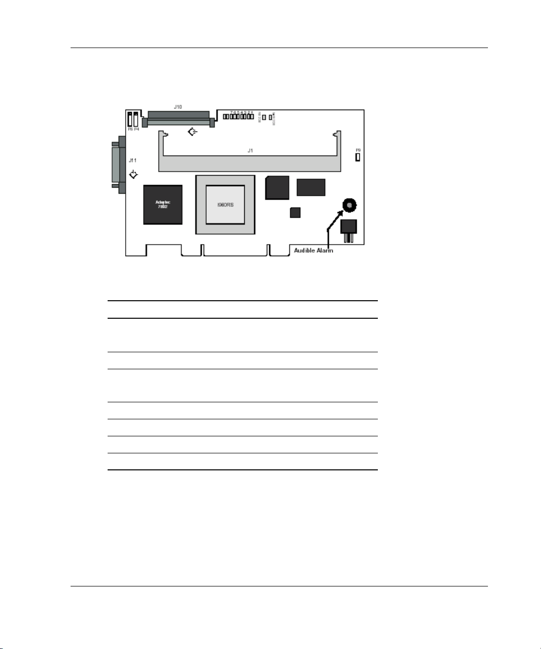
Board Layout
About Your New Controller
Table 2-1: Board Components
Item Description
P4 Pins 1-2 NVRAM clear
Pins 3-4 Misc (Reserved, do not use)
P6 Disk activity LED connector
P9 Pins 1-2 Retry (Reserved, do not use)
Pins 3-4 Reset (Reserved, do not use)
J1 168-pin DIMM socket
1…8, IRQ Adapter activity LEDs
J10 Internal Ultra160 Wide SCSI connector (Bus 0)
J11 External Ultra160 Wide SCSI connector (Bus 0)
HP 2100S SCSI RAID Controller User Guide 2-5
Page 18

About Your New Controller
Cache Memory Module
SDRAM memory provides 32 MB, 64 MB, or 128 MB of high-speed disk cache for
Adaptec SCSI RAID controllers. If ECC memory is installed, the cache is protected
by ECC, which automatically repairs errors in the data. The green ECC Enabled LED
is lit when ECC memory is installed. For the location of this LED, refer to “Board
Layout” in this chapter.
Adapted SCSI RAID Controller LEDs
Adaptec SCSI RAID controllers provide nine LEDs that let you visually monitor
controller activity. Several different controller states are indicated by the LED as
outlined in the following sections. Two additional LEDs indicate the status of the
cache memory on the controller. For the location of the LEDs on your controller,
refer to “Board Layout” in this chapter.
LED Display During Power-Up
During its power-up sequence, the controller passes through the following states in
sequence, as indicated by the LEDs:
NOTE: The address translation unit (ATU), PCI bridge, and cache module (if installed) must
be configured and enabled before the I
components are not configured or become disabled during the Fast Idle phase, the pattern will
return to the respective wait pattern for the affected component.
2O initialization can be completed. If any one of these
2-6 HP 2100S SCSI RAID Controller User Guide
Page 19

Table 2-2: LED Display During Power-Up
Condition LED Display
Memory mapped I/O LEDs 6 and 7 and LEDs 5 and 8 flash
alternately while the controller waits for the host
computer to initialize the ATU on the PCI bus.
Bridge LEDs 5 and 7 and LEDs 6 and 8 flash
alternately while the controller waits for the host
computer to initialize its PCI-to-PCI bridge.
Fast idle The controller enters a fast idle pattern while
waiting for the I
the address translation unit (ATU) and PCI
bridge have been enabled.
LED Display During Controller Idle
When no commands are in progress and all bus activity has ceased, the controller
enters the idle state. This is indicated by a rotating pattern in LEDs 1 through 8.
About Your New Controller
2O initialization commands after
LED Display During Controller Active
When the power-up sequence is complete, viewing the LEDs can help you determine
the operating status of the controller. These LED patterns are also useful for
troubleshooting. For more information on interpreting LED patterns, refer to
Appendix C, “Troubleshooting.”
Table 2-3: LED Display During Controller Active
LED Function
1 Heartbeat. Indicates that controller interrupts are enabled and that
the controller is alive. During controller activity, this LED flashes
four times a second.
2 Indicates the occurrence of a non-maskable interrupt (NMI) to the
I/O processor on the controller.
continued
HP 2100S SCSI RAID Controller User Guide 2-7
Page 20

About Your New Controller
Table 2-3: LED Display During Controller Active continued
LED Function
3 Indicates the controller’s internal operating system is in its idle
loop.
4 Indicates that the controller’s internal operating system is
processing an interrupt.
5 Reserved for future use.
6 Indicates that the cache controller is using DMA to perform a data
transfer.
7 Indicates the controller is generating parity information for a RAID
5 array (hardware XOR).
8 Indicates that there is a command on the SCSI bus. IRQ Lit only
when the controller activates an interrupt on the host PCI bus.
Cache Status LEDs
Two LEDs on the Adaptec SCSI RAID controller indicate the status of the onboard
cache RAM. For the location of the LEDs on your controller, refer to “Board Layout”
in this chapter.
• • The green ECC Enabled LED is lit when the installed DIMMs are ECC memory
modules. This indicates that the controller data cache is ECC protected.
The red ECC Error LED is lit when a correctable or non-correctable error has
been detected in one of the ECC DIMMs. After the error has been corrected, the
LED will be on until the controller is powered down. Cache failure information is
recorded in the controller error log.
2-8 HP 2100S SCSI RAID Controller User Guide
Page 21

Installation Overview
The process of installing a Adaptec SCSI RAID controller consists of the following
steps:
1. Configure device IDs, cables, and termination for SCSI devices in the host
system.
2. If you are expanding your cache memory, plug the appropriate modules onto the
controller.
3
Installing Your Controller
3. Install the controller and storage devices in the appropriate enclosures. Attach all
cables between the controller and the storage devices.
4. Run Storage Manager on ROM (SMOR) by pressing Ctrl+A during system boot
to configure the controller’s SCSI termination and verify proper hardware
configuration. You can also use SMOR to configure your storage subsystem and
disk arrays.
5. If you are setting up the computer system for the first time, install the operating
system on one of the controller’s disk drives or arrays.
6. Install any required operating system drivers. During this process, you should
also install any driver updates for your Adaptec controller. For additional
information, refer to Chapter 4, “Installing Adaptec SCSI RAID Software.”
HP 2100S SCSI RAID Controller User Guide 3-1
Page 22

Installing Your Controller
Configuration
SCSI devices must be configured before use. This configuration process includes
enabling or disabling SCSI termination for the devices and setting the SCSI IDs for
each device.
Narrow and Wide SCSI
The SCSI devices you will be installing can be either Narrow (8-bit) or Wide (16-bit)
SCSI devices. Wide SCSI disk drives allow data to be transferred at twice the rate of
8-bit devices. Some SCSI devices such as tape and CD-ROM drives still use an 8-bit
interface.
The Wide SCSI bus is backward compatible with Narrow SCSI devices, allowing
both types of SCSI devices to be used on the same controller. Narrow SCSI devices
must be connected to Channel 0 which supports the 8-bit bus.
IMPORTANT: If you use 8-bit and 16-bit devices on a single 16-bit SCSI cable, Wide devices
must be at the physical end of the bus. This ensures that the 16-bit signals are correctly
terminated.
Attaching a single-ended SCSI device to an LVD bus will cause the bus to run at Ultra SCSI
speed (20 MHz) for all devices.
Configuring Cables
CAUTION: The SCSI I/O ports supply 5V DC and are capable of delivering
approximately 2A DC current. Ensure that the interconnecting cables used are
adequate for this amount of current.
Adaptec SCSI RAID controllers have Wide SCSI busses with one internal and one
external SCSI connector for each bus.
Internal and external SCSI cables, connector adapters, and terminators can be
purchased from a supplier of your choice or directly from Adaptec through our online
web store at
www.adaptec.com
3-2 HP 2100S SCSI RAID Controller User Guide
Page 23

Configuring SCSI Termination
The devices on each physical end of a SCSI cable must be terminated. Depending
upon how you configure your system, you will either terminate two SCSI devices, or
the SCSI controller and one peripheral SCSI device.
IMPORTANT: If you are using multiple SCSI busses on a single controller, each separate bus
must be terminated.
SCSI termination for Adaptec SCSI RAID controllers is configured through the
SMOR utility or from the Configure Host Bus Adapter window in Storage Manager.
The controller has four possible termination settings.
Table 3-1: Termination Settings
Setting Function
Auto The default setting. This setting can be used for all cabling
conditions, except where two Narrow (8-bit) cables are
attached or both a Narrow and Wide cable are used. For this
case, use High Only.
Disabled Turns off controller termination unconditionally.
Enabled Turns on controller termination unconditionally.
High Only Terminates only the additional signals that are used on Wide
SCSI devices. This allows a Narrow cable or a Wide and
Narrow cable to be simultaneously attached to the controller.
Installing Your Controller
High Only termination is available only for devices on Bus 0. Devices on the second
bus (Bus 1) must have 16-bit termination.
By using a 68-pin to 50-pin SCSI cable adapter, an 8-bit SCSI device can be attached
to a Wide SCSI cable along with Wide SCSI devices. However, the device at the end
of the cable must be a Wide SCSI device so that all SCSI signals are terminated. For
internal and external cables where one cable is an 8-bit (Narrow) SCSI cable, set the
controller termination to High Only.
HP 2100S SCSI RAID Controller User Guide 3-3
Page 24

Installing Your Controller
The following illustrations show various SCSI cabling examples. Terminate your
SCSI devices as shown in the examples, ensuring that only the devices at the ends of
the cables are terminated.
3-4 HP 2100S SCSI RAID Controller User Guide
Page 25

Configuring Device IDs
The SCSI specification allows up to seven SCSI devices (and a controller) to be
connected to a single 8-bit SCSI bus. A Wide SCSI bus can support up to 15 devices
and the controller.
All SCSI devices, including the controller, must be assigned a unique SCSI ID. SCSI
IDs, which are typically set using jumpers or switches on peripheral devices, can be
assigned any number from 0 to 7 for 8-bit SCSI devices or 0 to 15 for Wide SCSI
devices.
Set the SCSI ID of each SCSI device attached to the controller to a unique ID number
between 0 and 6. The Adaptec SCSI RAID controller is set to ID 7 by default (most
SCSI controllers use ID 7). Wide SCSI devices can also use SCSI IDs 8 through 15.
SCSI IDs can be duplicated on the same controller if the devices using the same ID
are not attached to the same bus.
If necessary, the Adaptec SCSI RAID controller ID can be changed to any ID 0
through 7. You can use SMOR to change the controller SCSI ID.
IMPORTANT: Changing the controller ID is not recommended. You should leave the Adaptec
SCSI RAID controller set at SCSI ID 7.
Installing Your Controller
Installation
The following sections describe how the components of your Adaptec SCSI RAID
controller are assembled. Use these instructions in the event you need to add or
remove a component.
Installing Cache Memory Modules
Adaptec SCSI RAID controllers support up to 128 MB of cache using onboard
memory sockets. For specific information about memory modules for cache memory,
refer to “Cache Memory” in Chapter 2, “About Your New Controller.”
HP 2100S SCSI RAID Controller User Guide 3-5
Page 26

Installing Your Controller
To install cache memory modules:
1. Install the modules in the socket as shown. For socket location, refer to “Board
Layout” in Chapter 2, “About Your New Controller.”
Press the DIMM firmly into the socket. Ensure that the clips are engaged in the
notches on both sides of the DIMM.
2. To confirm that the modules are properly installed, start SMOR and select the
controller to display the amount of cache memory reported.
Installing the Controller
1. Connect the computer’s disk activity LED cable to connector P6 on the
controller. For the location of this connector, refer to “Board Layout” in
Chapter 2, “About Your New Controller.”
2. Pins 1 and 3 of P6 are connected to +5V and pins 2 and 4 are connected to GND.
Ensure that the positive lead of the LED cable (usually a red wire or marked with
a red stripe) is attached to pin 1 or 3 and the negative lead (usually a black wire)
is attached to pin 2 or 4.
3. If you are using the internal SCSI cable, connect this cable to the controller.
4. Install the controller in an available 32- or 64-bit PCI bus slot and secure the
controller bracket to the host system cabinet with the screw provided.
5. In a system with multiple controllers, the controller that has the lowest BIOS
ROM address (typically, the lowest numbered PCI slot) will become the booting
controller.
3-6 HP 2100S SCSI RAID Controller User Guide
Page 27

6. Connect any external cables to the controller.
IMPORTANT: If you have disk drives attached to a SCSI controller with a Symbios chipset,
use SMOR to set the Bootable Devices option to Disable.
Determining the Booting Controller
Installing Your Controller
Adaptec SCSI RAID controllers are shipped with an Adaptec I
2O BIOS ROM
enabled for PCI assignment. This ROM BIOS intercepts and processes Int13 BIOS
calls with an embedded DOS driver.
The Adaptec I
2O BIOS ROM can be disabled or the address changed automatically
by the system’s Plug-and-Play BIOS. In systems with multiple controllers, the first
2O controller found during boot loads its BIOS and installs all of the Adaptec
I
hardware on the system.
Any additional Adaptec I
2O controllers that are found automatically detect the
presence of the first controller and disable their BIOS code. The disk controller that
has the lowest BIOS ROM address (typically, the lowest PCI slot number) will
become the booting controller.
Ensure that the Adaptec ROM occupies the lowest address if you want the Adaptec
controller to be the booting controller in a system with controllers from multiple
manufacturers.
Some system BIOS manufacturers select the smallest add-in BIOS as the first
candidate, therefore slot selection has no effect on which adapter BIOS loads first. In
this case, you need to disable the BIOS on selected adapters to control which adapter
is the boot controller. This procedure can also be helpful in situations where it is
physically difficult to manage the slot order.
Controller IRQ and Address
During the host system boot process, the host system BIOS should automatically
configure the Adaptec I
2O BIOS interrupt level (IRQ) and memory location for all
Adaptec PCI controllers in the system.
If problems occur, refer to Appendix C, “Troubleshooting,” for additional help.
HP 2100S SCSI RAID Controller User Guide 3-7
Page 28

Installing Your Controller
NVRAM Reset
Adaptec SCSI RAID controllers retain their setup parameters even when powered
off. These parameters are stored on the controller in an area of nonvolatile memory
(NVRAM). There is a possibility that, through improper configuration, the controller
can be put into a state where it hangs the system during boot. If this happens, the
parameters stored in the NVRAM can be restored to their default settings by the
following procedure:
1. Turn off power to the system.
2. Place a shorting jumper across pins 1 and 2 of P4 on the controller. For the
location of P4 on your controller, refer to “Board Layout” in Chapter 2, “About
Your New Controller.”
3. Power on the system and wait until LEDs 3, 5, 7, and 8 on the controller begin
flashing.
4. Turn off power to the system and remove the jumper.
5. Restart the host system. If the system restarts normally, the controller can now be
configured using SMOR.
If the system fails to boot, refer to Appendix C, “Troubleshooting,” for additional
information.
3-8 HP 2100S SCSI RAID Controller User Guide
Page 29

Installing Adaptec SCSI RAID Software
Microsoft Windows 2000
The following sections describe procedures for installing Adaptec SCSI RAID
controllers under Windows 2000. Two installation scenarios are described in this
chapter:
• • Installing on a new system
Adding to an existing system
IMPORTANT: The driver for Windows 2000 does not include a digital signature. You may
receive one or more warning messages about this condition. Bypass the warnings and
continue with the installation. The driver will function normally when the upgrade or install is
complete.
4
It is necessary to make adjustments to certain Adaptec 2100S RAID Controller setups
to ensure uninterrupted service. This document describes these setups and presents
corrective action.
Power Management with Windows 2000
Under Windows 2000, it is recommended that you disable Power Options while the
Adaptec 2100S RAID Controller is building, rebuilding, or being verified. Otherwise,
when the system enters Standby or Hibernate Mode, the Adaptec 2100S RAID
Controller operation will stop.
HP 2100S SCSI RAID Controller User Guide 4-1
Page 30

Installing Adaptec SCSI RAID Software
When the system is restarted, the operation will restart from the beginning. To
prevent this from happening, configure the Power Options feature to not enter
Standby or Hibernate:
• • To prevent the system from entering Standby, select Start, Settings, Control
Panel, Power Options, Power Option Properties, Power Schemes, and then
set System Standby to Never.
To prevent the system from entering Hibernate, select Start, Settings, Control
Panel, Power Options, Power Option Properties, Hibernate, and then deselect
Enable hibernate support.
Installing on a New System
IMPORTANT: You only have a brief opportunity (five seconds) to press F6 during the install
startup. A prompt will appear at the bottom of the screen when the F6 key is active. If you do
not press F6 at this time, you must restart the Microsoft Windows 2000 install process to
complete this procedure correctly.
1. Before you start your installation, insert the HP start-up CD on a Windows
platform, and follow instructions for creating a driver floppy for the 2100S.
2. When the Windows 2000 installation starts, a blue screen will appear after the
hardware detection message. When prompted to install a third-party driver,
press F6.
3. When prompted, insert the driver floppy into your floppy drive and select
Adaptec I2O RAID Host Adapter Driver for Windows 2000. Press Enter and
follow the instructions.
4. When Windows 2000 starts for the first time it will start a New Hardware
Wizard:
a. Click Next.
b. Select Search for suitable driver for my device.
c. Click Next.
5. Insert the driver floppy into your floppy drive. Select the floppy drive and click
Next. The wizard should find the Adaptec SCSI RAID Adapter.
6. Click Next and follow the instructions to complete this part of the installation.
4-2 HP 2100S SCSI RAID Controller User Guide
Page 31

7. Install the Adaptec Management Controller device when prompted.
Completing the installation requires that the system shutdown and restart. When the
restart is complete, continue with the following steps to complete the installation.
Adding to an Existing System
1. Follow the instructions for installing the Adaptec SCSI RAID controller in your
system. Refer to Chapter 3, “Installing the Controller.”
2. Before you start your installation, insert the HP start-up CD on a Windows
platform, and follow instructions for creating a driver floppy for the 2100S.
3. When you start Windows 2000 the Found New Hardware Wizard will start for a
SCSI/RAID Controller. Insert the driver floppy into your floppy drive. Select the
floppy as the source, then click Next.
4. Click Next in the next two windows that appear.
5. Follow the on-screen instructions to complete the Adaptec SCSI RAID
installation.
6. Install the Adaptec Management Controller device when prompted.
IMPORTANT: If you reset the NVRAM on the controller, any changes to your cache settings
return to the factory default.
Installing Adaptec SCSI RAID Software
HP 2100S SCSI RAID Controller User Guide 4-3
Page 32

Regulatory Compliance Notices
Regulatory Compliance Statements
Federal Communications Commission Radio Frequency Interference Statement
WARNING: Changes or modifications to this unit not expressly approved by
the party responsible for compliance could void the user’s authority to operate
the equipment.
A
This equipment has been tested and found to comply with the limits for a Class B
digital device, pursuant to Part 15 of the FCC rules. These limits are designed to
provide reasonable protection against harmful interference in a residential
installation. This equipment generates, uses, and can radiate radio frequency energy,
and if not installed and used in accordance with the instruction manual, may cause
harmful interference to radio communications. However, there is no guarantee that
interference will not occur in a particular installation. However, if this equipment
does cause interference to radio or television equipment reception, which can be
determined by turning the equipment off and on, the user is encouraged to try to
correct the interference by one or more of the following measures:
•
Reorient or relocate the receiving antenna.
•
Increase the separation between equipment and receiver.
•
Connect the equipment to an outlet on a circuit different from that to which the
receiver is connected.
•
Consult the dealer or an experienced radio/television technician for help.
HP 2100S SCSI RAID Controller User Guide A-1
Page 33

Regulatory Compliance Notices
• Use a shielded and properly grounded I/O cable and power cable to ensure
compliance of this unit to the specified limits of the rules.
This device complies with part 15 of the FCC rules. Operation is subject to the
following two conditions: (1) this device may not cause harmful interference and (2)
this device must accept any interference received, including interference that may
cause undesired operation.
European Union Compliance Statement
This Information Technology Equipment has been tested and found to comply with
the following European directives:
•
EMC Directive 89/336/EEC, as amended by 92/31/EEC and 93/68/EEC
•
EN 50081-1 (1992)
•
EN55022 (1994) Class B
•
EN 50082-1 (1992)
•
EN61000-4-2 (1998)
•
EN61000-4-3 (1998)
•
EN61000-4-4 (1995)
•
EN61000-4-5 (1995) Surges
A-2 HP 2100S SCSI RAID Controller User Guide
Page 34

Regulatory Compliance Notices
Australian/New Zealand Compliance Statement
This device has been tested and found to comply with the limits for a Class B digital
device, pursuant to the Australian/New Zealand standard AS/NZS 3548 set out by the
Spectrum Management Agency.
Canadian Compliance Statement
This Class B digital apparatus meets all requirements of the Canadian InterferenceCausing Equipment Regulations.
Cet appareil numérique de la classe B respecte toutes les exigences du Règlement sur
le matérial brouilleur du Canada.
Japanese Compliance (Voluntary Control Council Initiative)
End-User Software License Agreement
PLEASE READ CAREFULLY THE FOLLOWING TERMS AND CONDITIONS. BY
USING THE SOFTWARE YOU ARE AGREEING TO BE BOUND BY THESE TERMS
AND CONDITIONS. IF YOU DO NOT AGREE TO THESE TERMS AND CONDITIONS,
DO NOT USE THE SOFTWARE.
We are giving you a license to use Adaptec software and related documentation (“Software”).
You acknowledge that we are not selling you the Software but only letting you use it in
accordance with the following terms.
License. We are giving you limited permission to use the Software. You may use the Software
on computers that you own or lease in all of the locations you have computers. You may make
one copy of the Software in machine readable form but only for the purposes of back-up, and
only if you also copy Adaptec’s copyright notice and any proprietary legends.
Restrictions. You may not give copies of the Software to others and you may not let others
gain access to it. You may not post the Software, or otherwise make it available, in any form
on the internet or in other public places or media. YOU MAY NOT MODIFY, ADAPT,
HP 2100S SCSI RAID Controller User Guide A-3
Page 35

Regulatory Compliance Notices
TRANSLATE, RENT, LEASE, LOAN, RESELL FOR PROFIT, OR CREATE
DERIVATIVE WORKS BASED UPON, THE SOFTWARE OR ANY PART OF IT. Finally,
you may not de-compile, reverse engineer, disassemble or reduce the Software to a human
readable form.
Ownership. The Software is owned by Adaptec, Inc., who retains title and ownership and the
intellectual property rights to the Software and copies you make. The software is protected by
copyrights and patents.
Termination. You may terminate this License at any time, and it will automatically terminate
if you fail to comply with it. If terminated, you must destroy the Software and all copies you
have made.
Support. Adaptec is under no obligation to maintain or provide support for the Software.
Disclaimer of Warranty. YOU ACCEPT ALL RISKS WHICH MAY ARISE FROM YOUR
USE OF THE SOFTWARE, FOR EXAMPLE, ERRORS IN TRANSMISSION, OR
CORRUPTION OF EXISTING DATA OR SOFTWARE. ADAPETC MAKES NO
WARRANTIES, EXPRESS OR IMPLIED, AND SPECIFICALLY DISCLAIMS ANY
WARRANTY OF INFRINGEMENT OF THIRD PARTIES’ RIGHTS, WARRANTIES OF
MERCHANTABILITY AND OF FITNESS FOR A PARTICULAR PURPOSE. Some states
do not allow the exclusion of implied warranties, and the above limitation may not apply to
you. You may also have other rights which vary from state to state.
Limitation of Liability. UNDER NO CIRCUMSTANCES WILL ADAPTEC OR ITS
RESELLERS BE LIABLE TO YOU FOR ANY INCIDENTAL, CONSEQUENTIAL, OR
INDIRECT DAMAGES, FOR EXAMPLE, LOST PROFITS, OR LOSS OF DATA, EVEN IF
ADPATEC HAS BEEN ADVISED OF THE POSSIBILITY OF SUCH DAMAGES.
Some states do not allow the exclusion or limitation of liability, and the above exclusion may
not apply to you.
Export. You may not export this Software unless you have complied with applicable United
States or foreign government laws.
US Government Restricted Rights. If this Software is purchased under a GSA contract, the
Software’s use, reproduction and disclosure is subject to the applicable ADP Schedule
contract. If the Software is acquired under a Odd or civilian contract, the Software’s use,
duplication and disclosure is subject to 48 CFR 12.212 of the Federal Acquisition Regulations
and 49 CFR 227.7202 of the Odd Supplement.
General. You assume full responsibility for the legal and responsible use of the Software. You
agree that this License is the complete agreement between you and us (and that any verbal or
written statements that are not reflected in this License, or any prior agreements, are
superseded by this License). To be effective, an amendment of this License must be in writing
and signed by both you and us. Should any provisions of this License be held to be
unenforceable, then such provision shall be severable from this License and shall not effect the
remainder of the License. This License shall be governed by California law. All rights in the
Software not specifically granted in this License are reserved by Adaptec.
A-4 HP 2100S SCSI RAID Controller User Guide
Page 36

Regulatory Compliance Notices
Should you have any questions concerning this Agreement, you may contact Adaptec by
writing to:
Adaptec, Inc.
Legal Department
691 South Milpitas Boulevard
Milpitas, California 95035.
HP 2100S SCSI RAID Controller User Guide A-5
Page 37

B
Electrostatic Discharge
To prevent damage to the system, be aware of the precautions you need to follow
when setting up the system or handling parts. A discharge of static electricity from a
finger or other conductor may damage system boards or other static-sensitive
devices. This type of damage may reduce the life expectancy of the device.
To prevent electrostatic damage, observe the following precautions:
•
Avoid hand contact by transporting and storing products in static-safe containers.
•
Keep electrostatic-sensitive parts in their containers until they arrive at static-free
workstations.
•
Place parts on a grounded surface before removing them from their containers.
•
Avoid touching pins, leads, or circuitry.
•
Always be sure you are properly grounded when touching a static-sensitive
component or assembly.
•
When installing a component, use any available ejector levers or captive
installation screws to properly seat the bus connectors in the backplane or card
slot. These devices prevent accidental removal, provide proper grounding for the
system, and help to ensure that bus connectors are properly seated.
•
When removing a component, use any available ejector levers or captive
installation screws to release the bus connectors from the backplane or card slot.
•
Handle adapter cards by available handles or edges only. Avoid touching the
printed circuit boards or connectors.
HP 2100S SCSI RAID Controller User Guide B-1
Page 38

Electrostatic Discharge
Grounding Methods
Several methods for grounding exist. Use one or more of the following methods
when handling or installing electrostatic-sensitive parts:
•
Use a wrist strap connected by a ground cord to a grounded workstation or
computer chassis. Wrist straps are flexible straps with a minimum of 1 megohm
±10 percent resistance in the ground cords. To provide proper ground, wear the
strap snug against the skin.
•
Use heel straps, toe straps, or boot straps at standing workstations. Wear the
straps on both feet when standing on conductive floors or dissipating floor mats.
•
Use conductive field service tools.
Use a portable field service kit with a folding static-dissipating work mat.
•
If you do not have any of the suggested equipment for proper grounding, have an
authorized reseller install the part.
For more information on static electricity or assistance with product installation,
contact your authorized reseller.
B-2 HP 2100S SCSI RAID Controller User Guide
Page 39

This appendix provides answers to many Frequently Asked Questions (FAQ). If a
situation occurs that is not covered in this appendix, or if the recommendations here
do not correct the problem, contact a technical support representative.
Problem 1
When the Adaptec I2O BIOS displays the peripheral devices at system boot, a device
fails to appear.
C
Troubleshooting
Solution 1
The following conditions can cause this to occur:
•
The device ID might be set to the same ID as the Adaptec controller (ID 7).
Ensure that all devices have a unique ID.
•
The device might not be powered on.
•
The device is not connected to the SCSI cable or the connection is loose.
HP 2100S SCSI RAID Controller User Guide C-1
Page 40

Troubleshooting
Problem 2
In addition to the Adaptec SCSI RAID controller, the system contains another
manufacturer’s SCSI controller and hangs during boot.
Solution 2
•
The other controller fails to correctly implement extended BIOS data area
(EBDA) usage rules. Use SMOR to try a different setting for the EBDA
Relocation parameter or rearrange the controller slot assignments.
•
If your system BIOS supports configuring the boot order, you can also try
changing those settings.
Problem 3
The system contains another manufacturer’s SCSI controller in addition to the
Adaptec SCSI RAID controller. During boot, messages from each controller’s BIOS
appear, but one controller cannot communicate with its attached drives.
Solution 3
•
The other controller fails to properly implement EBDA usage rules. Use SMOR
to try a different setting for the EBDA Relocation parameter or rearrange the
controller slot assignments.
•
If your system BIOS supports configuring the boot order, you can also try
changing those settings.
C-2 HP 2100S SCSI RAID Controller User Guide
Page 41

Problem 4
Microsoft Windows NT displays a blue screen error message that references the
system video controller.
Solution 4
The video controller fails to properly implement EBDA usage rules. Use SMOR to
enable the EBDA Relocation option.
Problem 5
The controller fails to respond and the IRQ LED (and possibly other LEDs) remains
lit. For the location of the LEDs on the controller, refer to “Board Layout” in
Chapter 2, “About Your New Controller.”
Solution 5
The IRQ LED indicates that the controller IRQ assignment is pending. This usually
indicates an IRQ conflict with another card. Ensure that each card is set to a unique
IRQ.
Troubleshooting
HP 2100S SCSI RAID Controller User Guide C-3
Page 42

Troubleshooting
Problem 6
The controller does not respond and one of the following LED patterns occurs at
power-up:
•
LEDs 6 and 7 alternating with LEDs 5 and 8
•
LEDs 5 and 6 alternating with LEDs 7 and 8
•
LEDs 5 and 7 alternating with LEDs 6 and 8
Solution 6
•
These patterns indicate that the controller is not being configured by the
motherboard BIOS. Adaptec SCSI RAID controllers require a motherboard BIOS
that supports multifunction devices, where one of the devices is a PCI bridge. All
Adaptec SCSI RAID controllers require a BIOS that supports large memorymapped address ranges.
•
Refer to the Adaptec SCSI RAID read.me file on the Adaptec CD for
information about motherboard compatibility and a list of motherboards that
Adaptec has tested with Adaptec SCSI RAID products.
C-4 HP 2100S SCSI RAID Controller User Guide
Page 43

Problem 7
The controller fails to respond and one of the following patterns of LEDs flash once
per second at power-up:
•
7, 6, 5, 2, 1 None
•
7, 6, 5, 3, 1 High
•
7, 6, 5, 3, 2 Mismatch
•
7, 6, 5, 3, 2, 1 Invalid
Solution 7
These patterns indicate a problem with the memory modules on the controller.
None—Either no memory modules were detected on the controller, or there is no
module installed.
High—Too much memory has been detected on a controller. Remove memory so
that the total is less than or equal to 128 MB.
Troubleshooting
Invalid—A memory module smaller other than 32, 64, or 128 MB has been detected.
Use only 32, 64 or 128 MB capacity memory modules.
Problem 8
The controller fails to respond and various LEDs in the 1–4 range flash once per
second.
Solution 8
This pattern indicates an internal microprocessor trap occurred in the controller.
Remove all attached devices, cables and retry. If the trap error disappears, reconnect
the cables and devices, one device at a time, until the faulty device or cable is
isolated. If the error persists, contact your technical support representative.
HP 2100S SCSI RAID Controller User Guide C-5
Page 44

Troubleshooting
Problem 9
Pressing Ctrl+A to access SMOR does not work or the information displayed is
garbled.
Solution 9
If this happens, use the following procedure to restore the parameters in the NVRAM
to their default settings:
1. Turn off power to the system.
2. Place a shorting jumper across pins 1 and 2 of P4 on the controller.
3. Power on the system and wait until the LEDs 3, 5, 7, and 8 on the controller
begin flashing.
4. Turn off power to the system and remove the jumper.
You can now reconfigure the controller using SMOR.
Problem 10
You want the system to boot from a drive that is not attached to an Adaptec
controller. However, during boot, the Adaptec I
2O BIOS message appears first which
indicates that a drive attached to an Adaptec controller will be the boot drive.
Solution 10
Use SMOR to disable the Boot Enable parameter for that controller. This will
prevent the Adaptec controller from being used as the booting controller for system.
C-6 HP 2100S SCSI RAID Controller User Guide
Page 45

Problem 11
The Adaptec SCSI RAID controller I2O BIOS reports the drive as a disk instead of a
drive.
Solution 11
This typically happens when a drive that is attached to an Adaptec SCSI RAID
controller has been formatted with a sector size other than 512 bytes. Use SMOR to
reformat the drive with 512-byte sectors. This can also occur if the drive is the 9th or
higher logical drive attached to the controller.
IMPORTANT: Using SMOR to set Bootable Devices to Disabled as in the previous problem
will result in the same symptoms. If you require access to disk drives connected to the Adaptec
SCSI RAID controller during the boot process, change Bootable Devices to Normal.
Problem 12
Although the SCSI devices can be accessed by the Adaptec SCSI RAID controller,
the fault LEDs on the devices in a RAIDstation storage cabinet do not flash during
boot-up and the Adaptec SCSI RAID controller does not detect drive swaps or
cabinet failures.
Troubleshooting
Solution 12
These symptoms indicate that the RAIDstation storage cabinet status signals are not
being properly received by the Adaptec SCSI RAID controller.
For SAF-TE or SES: this can result from a failed enclosure monitoring module in the
subsystem cabinet.
HP 2100S SCSI RAID Controller User Guide C-7
Page 46

Troubleshooting
Problem 13
After updating the Adaptec SCSI RAID controller firmware or BIOS and rebooting,
the adapter does not respond.
Solution 13
The update may have been unsuccessful. The controller is now in a state in which it
hangs the system during boot. If this happens, the parameters in the NVRAM can be
restored to their default settings using the following procedure:
1. Turn off power to the system.
2. Place a shorting jumper across pins 1 and 2 of P4 on the controller.
3. Power on the system and wait until the LEDs 3, 5, 7, and 8 on the controller
begin flashing.
4. Turn off power to the system and remove the jumper.
You can now reconfigure the controller using SMOR.
Problem 14
After updating the Adaptec SCSI RAID controller firmware or BIOS and rebooting,
LEDs 1 and 5 or 2 and 5 flash once per second.
Solution 14
These patterns indicate that the adapter startup code detected a firmware checksum
error or a flash error. Attempt the firmware update procedure again by using the
procedure in the following Problem description to recover from this condition.
C-8 HP 2100S SCSI RAID Controller User Guide
Page 47

Problem 15
A firmware upgrade is unsuccessful, causing the controller to hang.
Solution 15
The new firmware can be temporarily disabled and the upgrade attempted again by
following the steps below:
1. Power-off the system.
2. Place shorting jumpers across pins 1 and 2 and pins 3 and 4 of P9 on the
controller.
3. Insert the SMOR boot disk and power on the system. This will start SMOR.
NOTE: The SMOR boot disk image is available from the Adaptec Technical Support site.
The download file contains the disk image and instructions for use.
4. Use SMOR to update the firmware. You must restore all three components of the
flash ROM, firmware,
5. Power-off the system and return the jumpers to their original positions.
Troubleshooting
I2O BIOS, and SMOR.
6. Insert the card in a host system PCI slot.
7. Remove the SMOR boot disk from your floppy disk drive and power-up the
system.
Problem 16
After an upgrade of the I2O BIOS only, pressing Ctrl+A at the system prompt
displays the message:
Card not configurable.
Solution 16
Perform a full firmware upgrade for SMOR to correct this condition.
HP 2100S SCSI RAID Controller User Guide C-9
Page 48

Troubleshooting
Problem 17
The floppy disk drive cannot be accessed after installing an Adaptec controller.
Solution 17
Use SMOR to enable the EBDA Relocation option.
Problem 18
The controller’s audible alarm is sounding during normal operation.
Solution 18
This indicates a drive has failed. Restart the host system and run SMOR to identify
the failed drive. The alarm will stop when SMOR finishes the initial system scan.
Replace the failed drive and start a rebuild operation for the array.
C-10 HP 2100S SCSI RAID Controller User Guide
 Loading...