

Page 1

HP SureStore
Fibre Channel SCSI Bridge 2100 ER
User Guide
Edition 3
Part Number C6340-90003
February 2000
Printed in: Greeley, CO USA
© Copyright 2000 Hewlett-Packard Company
Page 2

Notice
This document contains information that is protected by copyright. All
rights are reserved. No part of this document may be photocopied,
reproduced, or translated to another language. The information
contained in this document is subject to change without notice.
See Appendix C for important safety and regulatory information.
Warranty
HP PRODUCT: HP SureStore 2100 ER SCSI Fibre Channel Bridge
C6340F
DURATION OF LIMITE D WARRANTY: Two Years
1. HP warran ts HP hardware, acce ssories, and supplies against defects
in materials and workmanship for the period specified above. If
Hewlett-Packard receives notice of such defects during the warranty
period, Hewlett-Packard will, at its option, either repair or replace
products which prove to be defective. Replacement products may be
either new or like-new.
2. HP warrants that HP software will not fail to execute its
programming instructions, for the period specified above, due to
defects in material and workmanship when properly installed and
used. If HP receives notice of such defects during the w arranty period,
HP will replace software media that does not execute its
programming instructions due to such defects.
3. HP does not warrant that the operation of HP products will be
uninterrupted or error free. If HP is unable, within a reasonable time ,
to repair or replace any product to a co ndition as warranted, customer
will be entitled to a refund of the purchase price upon prompt return
of the product.
4. HP products may contain remanufactured parts equivalent to new in
performance or may be been subject to incidental use.
ii
Page 3

5. The warranty period begins on the date of delivery or on the date of
installation if installed by HP. If customer schedules or delays HP
installation more than 30 days after delivery, warranty begins on the
31st day from delivery.
6. Warranty does not apply to defects resulting from (a) improper or
inadequate maintenance or calibration, (b) software, interfacing,
parts or supplies not s upplied by H P, (c) unauthorized modificati on or
misuse, (d) operation outside of the published environmental
specifications for the products, or (e) improper site preparation or
maintenance.
7. TO THE EXTENT ALLOWED BY LOCAL LAW, THE ABOVE
WARRANTIES ARE EXCLUSIVE AND NO OTHER WARRANTY
OR CONDITION, WHETHER WRITTEN OR ORAL, IS EXPRESSED
OR IMPLIED AND HP SPECIFICALL Y DISCLAIMS ANY IMPLIED
WARRANTIES OR CONDITIONS OF MERCHANTABILITY,
SATISFACTORY QUALITY, AND FITNESS FOR A PARTICULAR
PURPOSE.
8. HP will be liable for damage to tangible property per incident up to
the greater of $300,000 or the actual amount paid for the product that
is the subject of the claim, and for damages f or bodily injury or deat h,
to the extent that all such damages are determined by a court of
competent jurisdiction to have been directly caused by a defe ctive HP
product.
9. TO THE EXTENT ALLOWED BY LOC AL LA W, THE REMEDIES IN
THIS WARRANTY STATEMENT ARE THE CUSTOMER’S SOLE
AND EXCLUSIVE REMEDIES. EXCEPT AS INDICATED ABOVE,
IN NO EVENT WILL HP OR ITS SUPPLIERS BE LIABLE FOR
LOSS OF DATA OR FOR DIRECT, SPECIAL, INCIDENTAL,
CONSEQUENTIAL (INCLUDING LOST PROFIT OR DATA), OR
OTHER DAMAGE, WHETHER BASED IN CONTRACT, TORT, OR
OTHERWISE.
iii
Page 4

Printing History
This guide is the first edition of all included material. The guide printing
date and part number indicate the current edition. The printing date
changes when a new edition is printed. (Minor corrections and updates
incorporated at reprint do not change this date.)
Edition 1: July 1998
Edition 2: December 1998: Added textual enhancements and
revised illustrations
Edition 3: February 2000: Added references to magneto-optical
devices and revised illustrations
iv
Page 5

Typographical Conventions
The following typographical conventions are used in this guide:
Italic font: Denotes important information.
KEYCAP : Denotes keystrokes.
Computer Output: Denotes information displayed in the control panel
and screen menu items that you select.
WARNING Warnings call attention to a procedure or practice that could
result in personal injury if not correctly performed. Do not
proceed until you fully understand and meet the required
conditions.
CAUTION Cautions call attention to an operating procedure or practice that could
damage the product if not correctly performed. Do not proceed until you
fully understand and meet the required conditions.
NOTE Notes provide information that can be helpful in understanding the
operation of the product.
v
Page 6

In This Guide
In this guide, the following areas are described:
Chapter 1 Introduction: Contents of the parts kit, supported
products, environmental requirements for the Fibre
Bridge, and sample configurations.
Chapter 2 Setting Up the Fibre Bridge: How to install the Fibre
Bridge, including rackmounting and cabling.
Chapter 3 Operating the Fibre Bridge: The Fibre Bridge start
sequence, default settings (and how to change them),
and verification of the system setup.
Chapter 4 Troubleshooting Guide: Possible start sequence errors,
instructions for starting diagnostic procedures, and
how to proceed.
Appendix A Fibre Channel Overview: Background information
about the Fibre environment, including specifics
relating to the Fibre Bridge.
Appendix B Support and Customer Service: Resource information
about access to Hewlett-Packard customer support and
service.
Appendix C Safety and Regulatory Informat ion: Safety and
regulatory information for the Fibre Bridge.
Glossary A list of terms with definitions.
vi
Page 7

Contents
1. Introduction
Chapter Overview ....................................................................... 1-2
Fibre Bridge Components and Supported Products.................... 1-3
Product Components.............................................................. 1-3
Supported Products ................................................................ 1-5
Choosing a Location ................................................................... 1-6
Physical Specifications .......................................................... 1-6
Environmental Specifications ................................................ 1-6
Fibre Channel Configurations..................................................... 1-7
Basic Configuration ..............................................................1-7
Expanded Configuration (DLT libraries only) ...................... 1-8
Table of Contents
2. Setting Up the Fibre Bridge
Chapter Overview ....................................................................... 2-2
Mounting the Fibre Bridge in a Rack ......................................... 2-3
Assemble the L-brackets to the Fibre Bridge ........................ 2-4
Install the Fibre Bridge in the Rack ....................................... 2-5
Installing Cables ........................................................................ 2-6
Fibre Bridge Connection, Basic Configuration Example
(DLT and MO Libraries) .................................................... 2-6
Fibre Bridge Connection, Expanded Configuration Example
(DLT libraries only)............................................................ 2-8
Optical Fibre Channel Cable Options.................................... 2-11
3. Operating the Fibre Bridge
Chapter Overview ....................................................................... 3-2
Powering on the System ............................................................3-3
Changing the Default Settings .................................................... 3-5
Connecting the Serial Cable .................................................. 3-5
Serial Port Setup .................................................................... 3-7
Serial Port Operation ............................................................. 3-7
vii
Page 8

Contents
Making Configuration Changes.................................................. 3-9
Reconfigure the Fibre Channel Address ................................ 3-11
Change the Trace Settings ....................................................3-13
Fibre Channel to SCSI Mapping Configuration .................... 3-14
4. Troubleshooting Guide
Chapter Overview ....................................................................... 4-2
Troubleshooting .......................................................................... 4-3
Problem: Cannot Turn On the DLT Library ....................... 4-3
Problem: Cannot Turn On the MO Library ........................ 4-3
Problem: Cannot Turn On the Hub (DLT Only) ................ 4-4
Problem: Cannot Turn On the Fibre Bridge .........................4-4
Problem: Cannot Confirm the Library Connection ............ 4-4
A. Fibre Channel Overview
Overview..................................................................................... A-2
Defining Fibre Channel .............................................................. A-3
Implementing Fibre Channel ...................................................... A-5
Distributed Devices................................................................ A-5
Cabling Advantages............................................................... A-5
Working With Fibre Channel .................................................... A-6
Problems with Fibre Channel ..................................................... A-9
Physical Connections............................................................. A-9
Laser Power Control Systems................................................ A-11
Device Addressing ................................................................. A-11
B. Support and Customer Service
Chapter Overview ....................................................................... B-2
Supplies and Accessories............................................................ B-3
Hewlett-Packard Customer Support ........................................... B-4
Support Pack Service Contract .............................................. B-5
viii
Page 9

Contents
HP FIRST/QUICK FAX Faxback Services........................... B-5
Electronic Support Services................................................... B-8
Customer Care Centers .......................................................... B-9
Telephone Support After Warranty ....................................... B-11
C. Safety and Regulatory Information
Chapter Overview ....................................................................... C-2
CDRH Regulations (USA Only)............................................ C-3
United Kingdom Telecommunications Act 1984 .................. C-3
Herstellerbescheinigung......................................................... C-5
English Translation of German Sound Emission Directive... C-5
Turvallisuusyhteenveto.......................................................... C-6
English Translation of Finland Regulatory Information........ C-7
Japanese VCCI Statement...................................................... C-8
Table of Contents
Glossary
Index
ix
Page 10

Contents
x
Page 11

Tables
Table 1-1. Supplied Components . . . . . . . . . . . . . . . . . . . . . . . . . . . . . . 1-3
Table 1-2. Supported Products . . . . . . . . . . . . . . . . . . . . . . . . . . . . . . . . 1-5
Table 1-3. Physical Specifications of the Fibre Bridge . . . . . . . . . . . . . 1-6
Table 1-4. Location Criteria . . . . . . . . . . . . . . . . . . . . . . . . . . . . . . . . . . 1-6
Table 2-1. Assembly Components . . . . . . . . . . . . . . . . . . . . . . . . . . . . . . 2-3
Table 2-2. Fiber-Optic Cable Options . . . . . . . . . . . . . . . . . . . . . . . . . . 2-11
Table 3-1. Fibre Bridge Default Configuration Settings . . . . . . . . . . . . 3-8
Table A-1. Fibre Channel Supported Fabric Topologies . . . . . . . . . . . .A-4
Table of Tables
xi
Page 12

Tables
xii
Page 13

Figures
Figure 1-1. Sample Fibre Channel Configuration—Basic. . . . . . . . . . . 1-7
Figure 1-2. Sample Fibre Channel Configuration—
Minimum Expansion . . . . . . . . . . . . . . . . . . . . . . . . . . . . . . . . . . . . . . 1-8
Figure 1-3. Sample Fibre Channel Configuration—
Maximum Expansion . . . . . . . . . . . . . . . . . . . . . . . . . . . . . . . . . . . . . . 1-9
Figure 2-1. Assembling L-brackets to the Fibre Bridge . . . . . . . . . . . . 2-4
Figure 2-2. Mount the Fibre Bridge in the Rack . . . . . . . . . . . . . . . . . . 2-5
Figure 2-3. Fibre Bridge Connection, Basic Configuration
(DLT and MO Libraries). . . . . . . . . . . . . . . . . . . . . . . . . . . . . . . . . . . . 2-7
Figure 2-4. Fibre Bridge Connection, Expanded Configuration
(Minimum) (DLT Only) . . . . . . . . . . . . . . . . . . . . . . . . . . . . . . . . . . . . . . 2-9
Table of Figures
Figure 2-5. Fibre Bridge Connection, Expanded Configuration
(Maximum) (DLT Only). . . . . . . . . . . . . . . . . . . . . . . . . . . . . . . . . . . . . 2-10
Figure 3-1. Fibre Bridge, Back View . . . . . . . . . . . . . . . . . . . . . . . . . . . 3-4
Figure 3-2. Connecting the Serial Cable . . . . . . . . . . . . . . . . . . . . . . . . 3-6
Figure 3-3. Fibre Bridge Configuration, Main Menu . . . . . . . . . . . . . . 3-9
Figure 3-4. Fibre Bridge Configuration Menu . . . . . . . . . . . . . . . . . . . 3-10
Figure 3-5. Fibre Channel Configuration Menu . . . . . . . . . . . . . . . . . 3-11
Figure 3-6. Fibre Channel Addresses. . . . . . . . . . . . . . . . . . . . . . . . . . 3-12
Figure 3-7. Trace Settings Menu . . . . . . . . . . . . . . . . . . . . . . . . . . . . . 3-13
xiii
Page 14

Figures
xiv
Page 15

Introduction
1 Introduction
1-1
Page 16

Introduction
Chapter Overview
Chapter Overview
This chapter provides the following information:
• Fibre Bridge Components and Supported Products
• Choosing a Location
• Fibre Channel Configurations
1-2 Chapter 1
Page 17

Fibre Bridge Components and Supported Products
Fibre Bridge Components and
Supported Products
This section includes a list of all parts supplied with the Fibre Bridge,
products that Hewlett-Packard supports for use with the Fibre Bridge,
environmental considerations, and sample system configurations.
Product Components
Table 1-1 lists the parts that are supplied with the Fibre Bridge.
Table 1-1 Supplied Components
Item Quantity Description
Fe et 4 Rubber pads for bottom of
Introduction
Introduction
Fibre Bridge. (Not required
for rackmount installation.)
Fibre Channel SCSI
Bridge 2100 ER User
Guide CD-ROM
Filler Panel Decal 1 Adhesive-backed decal for
French Statement 1 A French regulatory
HP SureStore Fibre
Channel SCSI Bridge
2100 ER
Rackmount Hardware 2 Two L-brackets that fasten
Chapter 1 1-3
1 User Guide in English,
French, German, and
Japanese.
CD also contains a Fibre
Share Primer, and
Application Notes
filler panel, provided by rack
manufacturer.
requirement.
1 Fibre Bridge.
to the Fibre Bridge and
mount in a rack.
Page 18

Introduction
Fibre Bridge Components and Supported Products
Item Quantity Description
SCSI Cables
(for Digitial Linear T ape
libraries)
SCSI Cable
(for Magneto-Optical
libraries)
Serial Cable 1 RJ-11 to RJ-11 cable,
SW Optical FC Cable 1 Short Wave Optical Fibre
SW Optical GBIC 2 Gigabit Interface Converter.
Te rminator 2 Single-ended 68-pin D
User Guide 1 English manual.
Rackmount screws and
nuts
2 Two Single-ended, 2 meter
length - 68 pin high density.
2 Two Single-ended, 2 meter
length - 50-to-68 pin, high
density.
included for troublesh ooti ng
and reconfiguration
purposes only.
Channel Cable, 16 meter
length.
connector with screws.
1 package
(Includes
extra
parts)
Six (6) 6x 32 screws with
lock-washers, for mounting
the Fibre Bridge to
L-brackets.
Six (6) 10x32 screws and six
(6) clipnuts for installing the
L-brackets with Fibre
Bridge into a rack.
RJ-11 to DB9 Adapter 1 Adapter to use with the
RJ-11 to RJ-11 Serial Cable.
1-4 Chapter 1
Page 19

Introduction
Fibre Bridge Components and Supported Products
Supported Products
Table 1-2 shows the products that Hewlett-Packard supports for
connection with the Fibre Bridge:
Table 1-2 Supported Products
Product Description
HP DLT libraries and autoloaders
with single-ended SCSI
interfaces
HP magneto-optical (MO)
libraries with single-ended SCSI
interfaces
HP Fibre Channel hub Consult with your sales
HP Host bus adapter HHBA-5101B for NT Systems.
Introduction
Library models are subject to
change. Consult with your sales
representative.
Library models are subject to
change. Consult with your sales
representative.
representative for model of hub.
Chapter 1 1-5
Page 20

Introduction
Choosing a Location
Choosing a Location
Physical Specifications
The Fibre Bridge is des igned for rackmoun ting . The unit can b e mounted
in most standard 19-inch rack configurations. The physical
characteristics are as follows:
Table 1-3 Physical Specifications of the Fibre Bridge
Height 1.7 inches (4.2 cm)
Width 16.9 inches (42.9 cm)
Depth 9 inches (22.8 cm)
Physical package
weight
Approximately 8 pounds (3.6 kg)
Environmental Specifications
Choose a location that meets the following criteria:
Table 1-4 Location Criteria
Room temperature 40–104° F (5–40° C).
Humidity 5% to 80% relative humidity, non-condensing.
Power source AC power voltage: 100/120V to 220/240 V.
Clearance Rackmount configuration—requires 1 EIA
unit in a rack. 1 EIA = 1.75 inches (44 mm).
Requires 5 inches (125 mm ) cle arance be tween
the rear edge of the Fibre Bridge and the
backplane of the rack, to allow adequate room
for cables.
NOTE See Chapter 2 for rackmounting instructions.
1-6 Chapter 1
Page 21
Introduction
Fibre Channel Configurations
Fibre Channel Configurations
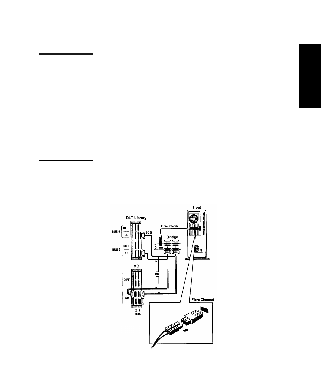
The Fibre Bridge is supported in a basic configuration on Digital Linear
Tape (DL T) and Magneto-Optical (MO) libraries. The bridge is support in
expanded configurations on DLT libraries. A basic configuration is
comprised of only one Fibre Bridge (two SC SI buses available) and a
host. Expanded configurations may include multiple hubs and hosts,
usually connected to one or more networks.
Basic Configuration
Figure 1-1 shows the Fibre Bridge in a basic configuration, including one
host or server, one Fibre Bridge, and one library.
NOTE Magneto-optical libraries are supported only on the basic configuration.
You may connect a maximum of two MO libraries (one on each SCSI bus
from the bridge).
Introduction
Figure 1-1 Sample Fibre Channel Configuration—Basic
Chapter 1 1-7
Page 22
Introduction
Fibre Channel Configurations
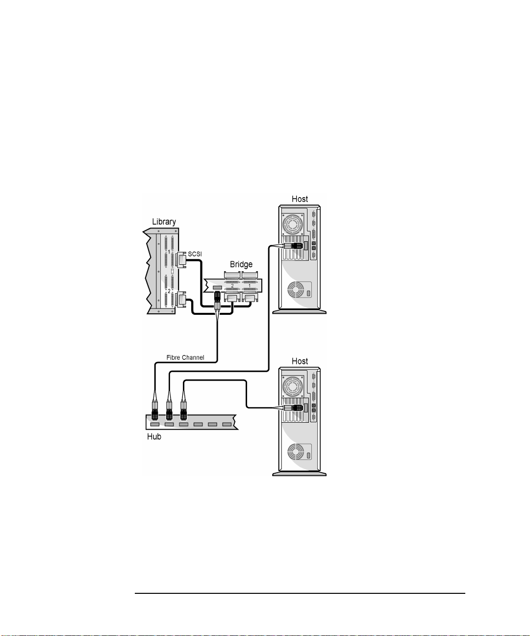
Expanded Configuration (DLT libraries only)
Figure 1-2 and Figure 1-3 shows the Fibre Bridge in two possible
expanded configurations . These configurations are supported on DLT
libraries only.
Figure 1-2 Sample Fibre Channel Configuration— Minimum Expansion
1-8 Chapter 1
Page 23
Introduction
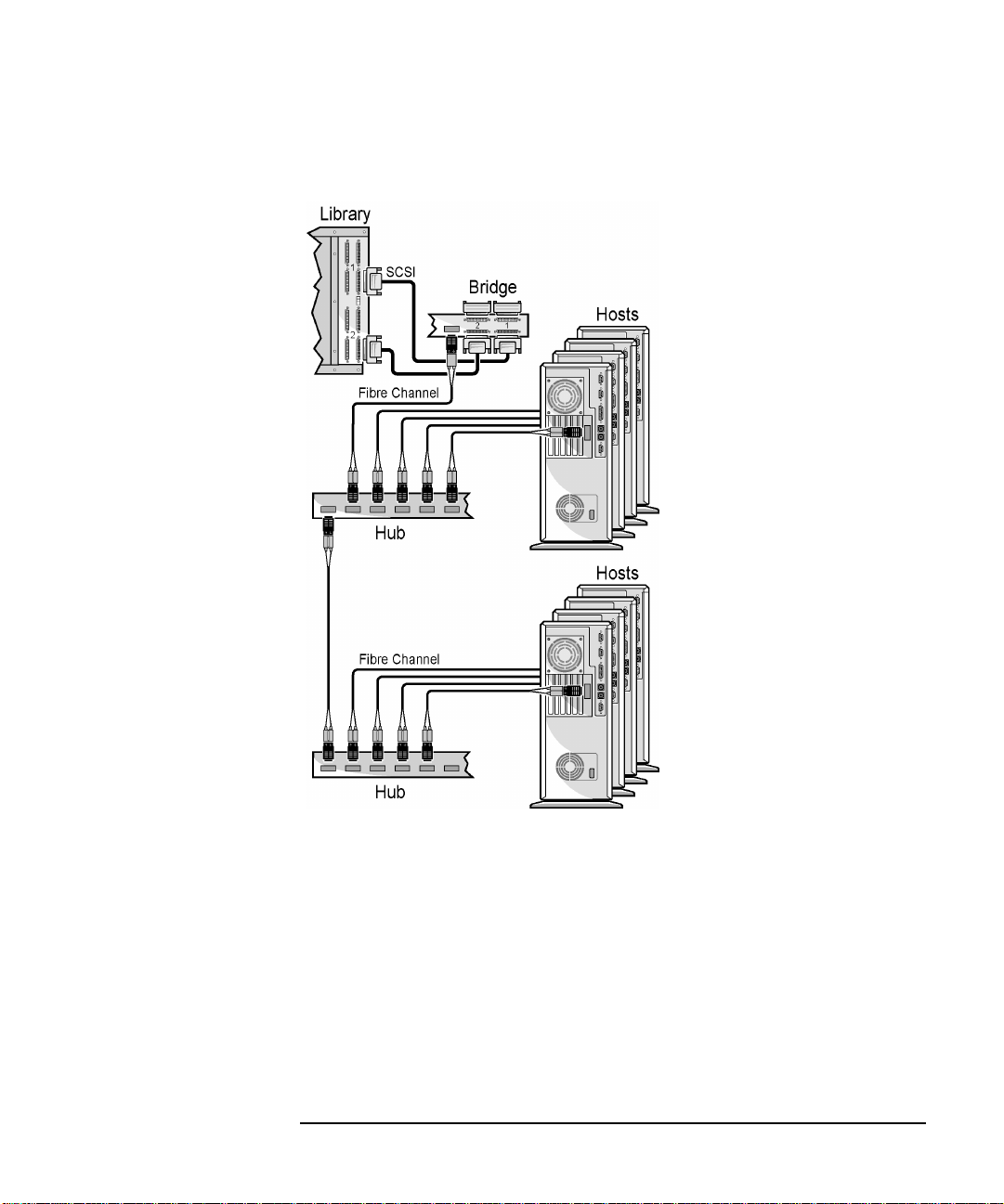
Fibre Channel Configurations
Figure 1-3 Sample Fibre Channel Configuration—Maximum Expansion
Chapter 1 1-9
Page 24

Introduction
Fibre Channel Configurations
1-10 Chapter 1
Page 25

Setting Up the
Fibre Bridge
2 Setting Up the Fibre Bridge
2-1
Page 26

Setting Up the Fibre Bridge
Chapter Overview
Chapter Overview
This chapter provides instructions on completing the following setup
procedures:
• Mounting the Fibre Bridge in a Rack
• Installing Cables
2-2 Chapter 2
Page 27

Setting Up the Fibre Bridge
Mounting the Fibre Bridge in a Rack
Mounting the Fibre Bridge in a Rack
Mounting the Fibre Bridge in a rack requires assembling L-brackets to
the Fibre B ri d ge a nd t he n mou n ti ng the L - br ackets to a r ac k . L- br ackets
allow the Fibre Bridge to be mounted in a fixed position, near the back of
a rack.
NOTE All connections and user displays are located on the back of the Fibre
Bridge. Consequently, mount toward the back of a rack.
Before you begin, verify you have the a ssembly components listed in
Table 2-1.
Table 2-1 Assembly Components
Tool 1 #2 Phillips screwdriver (not supplied).
Setting Up the
Fibre Bridge
Mounting
brackets
Rackmount
screws and
nuts
Filler panel
decal
1 pair L-brackets, for assembly with Fibre
Bridge.
1 package
(Includes
extra
parts)
1 Decal for filler panel, provided by
Six (6) 6x32 screws t o attac h Fibre B ridge
to L-brackets.
Six (6) 10x32 screws and six (6) clip nuts
for installing the Fibre Bridge (with
L-brackets attached) into a rack.
customer (supplied separately by rack
manufacturer).
Chapter 2 2-3
Page 28
Setting Up the Fibre Bridge
Mounting the Fibre Bridge in a Rack
Assemble the L-brackets to the Fibre Bridge
1. Facing the back of the Fibre Bridge, position the first L-bracket with
the mounting tab toward the back of the rack and pointing away from
the unit, as shown in Figure 2-1.
2. Insert 6x32 screws through the first and third holes from the
mounting tab and tighten. Use the first and third holes (from the
mounting tab end of the bracket) for mounting in a Hewlett-Packard
rack. (Non-HP racks may require mounting holes number two and
four. See note below.)
3. Follow the same procedure for the second L-bracket.
NOTE For non-HP racks, allow for cable turn: A minimum distance of 5 inches
(125 mm) is required between the back of the Fibre Bridge and the
backplane of the rack. When installing in racks where the mounting
holes in step 2 produces a distance less than 5 inches (125 mm), use the
second and fourth holes when attaching the mounting bracket to the
Fibre Bridge.
Figure 2-1 Assembling L-brackets to the Fibre Bridge
H
N
o
t
S
u
i
t
a
b
l
e
f
o
r
H
a
r
d
D
r
i
v
e
S
u
b
s
y
s
t
e
m
s
2-4 Chapter 2
Page 29
Setting Up the Fibre Bridge
Mounting the Fibre Bridge in a Rack
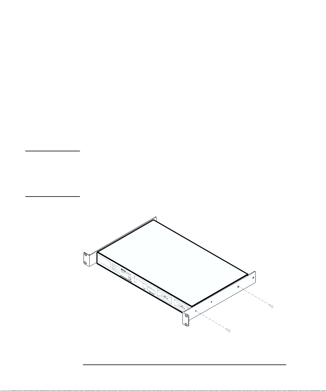
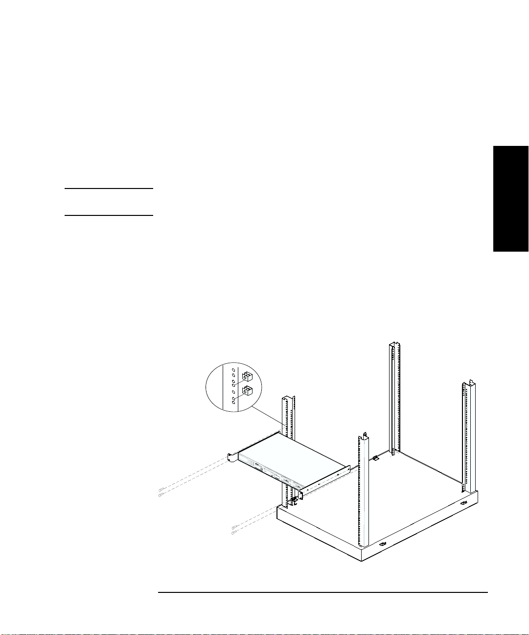
Install the Fibre Bridge in the Rack
1. Facing the back of the rack, install a total of four clip nuts above any
existing product, two into each of the rails. Install the clip nuts so
that the top nut aligns with the top hole of the L-bracket and the
other with the bottom hole. (Figure 2-2).
To ensure level mounting, verify that the clip nuts are in the same
position on the right and left rails.
NOTE The Fibre Bridge mounts from the bac k of the rac k. All user functio nality
is located on the back of the unit; no access to the front is required.
2. Holding the Fibre Bridge in position, align the holes in the mounting
brackets with the holes in the clip nuts.
3. Install four 10x32 screws into the clip nuts and hand-tighten.
4. Tighten all four screws.
5. Install the front filler panel (supplied by the rack vendor) and apply
the decal.
Figure 2-2 Mount the Fibre Bridge in the Rack
Setting Up the
Fibre Bridge
H
N
o
t
S
u
i
t
a
b
l
e
f
o
r
H
a
r
d
D
r
i
v
e
S
u
b
s
y
s
t
e
m
s
Chapter 2 2-5
Page 30

Setting Up the Fibre Bridge
Installing Cables
Installing Cables
The Fibre Bridge can be used in either basic or expanded system
configurations. This section provides the steps to install cables in both
configurations.
NOTE The following section explains overall configuration cabling. For
complete installation procedures, refer to the INSTALL subdirectory on
the CD-ROM shipped with the bri d ge.
Fibre Bridge Connection, Basic Configuration Example (DLT and MO Libraries)
CAUTION Be sure all devices in the configuration have been turned off and
disconnected from the power source before making any connections.
F ailure to disconnect all power could result in damage to the devices.
1. Properly shut down all peripheral devices that will be connected to
the Fibre Bridge, i ncluding the host. If the host compu ter is connected
to a network, check with the system administrator before switching
off power.
2. Connect the SCSI cable from bus 1 on the Fibre Bridge to bus 1 on the
library.
For a two-drive DLT library, connect a SCSI cable from bus 2 on the
Fibre Bridge to bus 2 on the library.
For a two-bus MO library, connect a SCSI cable from bus 2 on the
Fibre Bridge to bus 2 on the library.
NOTE A basic, point-to-point configuration is “One HBA to one bridge to one or
two SCSI buses.”
A two-drive DLT library uses both SCSI buses, so only one t w o-drive
DLT library may be connected to one HBA.
An MO library may be connected to each SCSI bus on a bridge, so two
MO libraries (maximum) may be connected to one HBA.
2-6 Chapter 2
Page 31

Setting Up the Fibre Bridge
3. Connect one end of the optical cable into the GBIC on th e Fibre
Bridge and the other end into the GBIC on the Fibre Channel HBA in
the host.
4. Connect the power cord from the Fibr e Bridge to an grounded outlet.
5. Confirm that all cable ends are connected securely and both ends of
the SCSI bus are properly terminated, as shown in F igure 2-3 on p age
2-7.
6. Go to “Powering on the System” in Chapter 3.
Figure 2-3 Fibre Bridge Connection, Basic Configuration
(DLT and MO Libraries)
Installing Cables
Setting Up the
Fibre Bridge
Chapter 2 2-7
Page 32

Setting Up the Fibre Bridge
Installing Cables
Fibre Bridge Connection, Expanded Configuration Example (DLT Libraries Only)
1. Properly shut down all peripheral devices that will be connected to
the Fibre Bridge, including the hub(s). Check with the system
administrator before turning off power to either hubs or libraries.
CAUTION Failure to turn off all power could result in damage to the devices.
2. Connect a S CSI cable from bus 1 on the Fibre Bridge to bus 1 on the
library one. For a two-drive library, connect a SCSI cable from bus 2
on the Fibre Bridge to bus 2 on the library.
3. Connect the optical cable from the Fibre Bridge to the hub.
4. Connect an optical cable from the hub to each host syste m.
If you have a 6-8 host system, you will need an additional hub. (See
Figure 2-3 and Figure 2-4 for examples of expanded configurations.)
5. Connect the power cord from Fibre Bridge one to an grounded outlet.
6. Confirm that all cable ends are connected securely and both ends of
each SCSI bus are properly terminated, as shown in Figure 2-4 or
Figure 2-5 on page 2-10.
7. See poweron instructions in Chapter 3.
2-8 Chapter 2
Page 33

Setting Up the Fibre Bridge
Installing Cables
Figure 2-4 Fibre Bridge Connection, Expanded Configuration (Minimum)
(DLT Only)
Setting Up the
Fibre Bridge
Chapter 2 2-9
Page 34

Setting Up the Fibre Bridge
Installing Cables
Figure 2-5 Fibre Bridge Connection, Expanded Configuration (Maximum)
(DLT Only)
2-10 Chapter 2
Page 35

Setting Up the Fibre Bridge
Installing Cables
Optical Fibre Channel Cable Options
The Fibre Bridge uses fiber-optic cables available in the lengths listed in
Figure 2-2:
Table 2-2 Fiber-Optic Cable Options
Product Number Length
D6980A 164 ft (50 m)
D6981A 328 ft (100 m)
NOTE For additional information regarding the Fibre Channel environment,
configuration, and other Fibre issues, refer to Appendix A, “Fibre
Channel Overview.”
Chapter 2 2- 11
Page 36

Setting Up the Fibre Bridge
Installing Cables
2-12 Chapter 2
Page 37

3 Operating the Fibre Bridge
Operating the
Fibre Bridge
3-1
Page 38

Operating the Fibre Bridge
Chapter Overview
Chapter Overview
This chapter provides the following information:
• Powering on the System
• Changing the Default Settings
• Making Configuration Changes
3-2 Chapter 3
Page 39

Operating the Fibre Bridge
Powering on the System
Powering on the System
The HP SureStore Fibre Channel SCSI Bridge 2100 ER is configured for
most Fibre Channel installations without intervention. The basic
configuration uses one Fibre Bridge connected directly to a Fibre
Channel Host Bus Adapter (HBA) within a host computer. In expanded
configurations (DLT libraries only), the Fibre Bridge may be connected to
either a Fibre Ch annel HBA or a Fibre Channel hub . Th e F ibre Bridge is
set up to support an HP single-ended SCSI library on a Fibre Channel
arbitrated loop.
Use the following sequence when powering on the sys tem:
NOTE Powering on each device in the proper sequence is important. When
devices are turned on out of order, communication failures may result.
1. Power on the library, which allows the Fibre Bridge to connect
properly to the library when it scans the SCSI bus.
2. Power on the F ibre Bridge. When you do, notice that the power
indicator comes on immediately. The Fault indicator may flash
momentarily. After about 30 seconds, the SCSI activity indicator will
flash once. The Fibre Channel activity indicator will not flash until
other devices have been attached and powered on.
3. Power on the hub, if required.
4. Power on the host.
(If DLT) If there are multiple hosts , power them on sequentially.
Order is important. Wait for for each host to finish booting before
powering on the next host.
NOTE If any fault indicators are encountered on the Fibre Bridge or other
equipment, consult the appropriate user gui de.
5. (If DLT) Install backup software.
Operating the
Fibre Bridge
Chapter 3 3-3
Page 40

Operating the Fibre Bridge
Powering on the System
Figure 3-1 Fibre Bridge, Back View
3-4 Chapter 3
Page 41

Operating the Fibre Bridge
Changing the Default Settings
Changing the Default Settings
The basic Fibre Bridge configuration assumes there is only one Fibre
Bridge included in the system. If this is a DLT installation and more
than one Fibre bridge will be installed, or if there is another Fibre
Channel device using the same address, you must change the fib re
channel address, using the serial port of the Fibre Bridge.
Connecting the Serial Cable
Using the serial cable is not necessary in most installations. The default
settings work in most configurations. Use the serial cable only if one of
the following situations occurs:
• The default configuration must be changed.
• A failure has occurred that requires diagnostic procedures. See
“Chapter 4: Troub les h o ot ing.”
If any of these scenarios occur , attach the serial cable and RJ-11 to DB9
adapter as shown in Figure 3-2 on page 3-6.
Operating the
Fibre Bridge
1. Plug the RJ-11 connector into the Fibre Bridge.
2. Plug the DB9 adapter into the Com1 or Com2 port of the computer.
3. Verify that the RJ-11 serial cable is properly plugged into the RJ-11
to DB9 adapter.
Chapter 3 3-5
Page 42

Operating the Fibre Bridge
Changing the Default Settings
Figure 3-2 Connecting the Serial Cable
4
H
N
o
t S
u
it
a
b
l
e
fo
r
H
a
rd
D
riv
e
S
u
b
s
ys
t
e
m
3
2
s
1
1Fibre Bridge
2 RJ-11 connector
3 Serial cable
4 RJ-11 to DB9 adapter
3-6 Chapter 3
Page 43

Operating the Fibre Bridge
Changing the Default Settings
Serial Port Setup
Before communicating, the PC serial port must be connected to t he Fibre
Bridge and terminal emulation software (Hyperterminal, or similar)
must be installed on the ho st. Configure t he terminal emulat ion program
to use the settings in Table 3-1 on page 3-8 for the PC’s serial port.
NOTE When initially powered on, the Fibre Bridge uses the default (or
previously set) baud rate during self-tests. After completing the
self-tests, pressing
itself to the baud rate used by the host.
ENTER several times causes the Fibre Bridge to reset
Serial Port Operation
The serial port on the Fibre Bridge connects to a terminal or computer
that is running a terminal emulator such as Hyperterminal on Windows
NT. The operator can then perform the following:
• Change the system addresses and address modes
Operating the
Fibre Bridge
• Check the results of the POST tests
• Change the operating leve l of diag nos tic rout in es
NOTE The serial port cannot be used to transfer data to devices on the SCSI
buses or on the Fibre Channel loop.
An EEPROM inside the Fibre Bridge stores configuration changes.
Because the Fibre Bridge stores its original settings, it can be reset to the
original configuration at any time. See Table 3-1 on page 3-8 for the
default configuration settings.
NOTE If there is trouble communicating between the serial port and the Fibre
Bridge, contact an HP service representative.
Chapter 3 3-7
Page 44

Operating the Fibre Bridge
Changing the Default Settings
Table 3-1 Fibre Bridge Default Configuration Settings
Serial Port • Baud rates: 9600, 19200, 38400, 57600, 115200
(baud rate will auto-configure).
• No handshake.
• No parity.
• 8 data bits.
• 1 stop bit.
Fibre
Channel
SCSI Initiator address 7.
Trace Debug
Level
• Hard address mode uses addres s 0x82.
• User may change both address mode and hard
address.
Bus automatically negotiates for wide ultra SCSI
performan ce, per AN SI SCSI specifications.
Only the initiator addr esses may be changed.
Each bus can be set to its own initiator address
independently of the other b u s.
Level 0, 1, 2, and 3.
3-8 Chapter 3
Page 45

Operating the Fibre Bridge
Making Configuration Changes
Making Configuration Changes
To mak e configuration changes, follow these steps:
1. Start your terminal emulation application software.
2. Press the
ENTER key. The following menu will display:
NOTE The user may need to press ENTER several times to prompt the Fibre
Bridge to recognize the serial port settings.
Figure 3-3 Fibre Bridge Configuration, Main Menu
3. Use the
the configuration. To select the option, type
press
Perform Configuration menu option to make changes to
1 on the keyboard and
ENTER to display the Fibre Bridge configuration menu.
Operating the
Fibre Bridge
Chapter 3 3-9
Page 46

Operating the Fibre Bridge
Making Configuration Changes
Figure 3-4 Fibre Bridge Configuration Menu
4. To initiate a change, enter the number of any item on the list. After
all changes have been complete d, save the changes by pressing
a on
the keyboard. To make changes take effect, restart the Fibre Bridge.
CAUTION Making changes under options B or C does not change the settings in
memory. Before closing the configuration menu and restarting the Fibre
Bridge, always select option A, “Save Configuration”.
3-10 Chapter 3
Page 47

Operating the Fibre Bridge
Making Configuration Changes
Reconfigure the Fibre Channel Address
Use the Fibre Channel Configuration menu to change from the hard
address mode to the soft address mode.
NOTE The Fibre Bridge de fault set ting is ha rd addressing , where the address is
preset to 71 (0x82). Use this procedure when an additional bridg e is
installed in a system or to resolve a Fibre Channel device ID conflict.
1. From the Configuration menu (Figure 3-4 on page 3-10), select option
2, Fibre Channel Configuration.
2. To toggle between hard addressing and soft addressing, select option
1.
3. To choose a new address, select option 2 and enter a new address from
the table in Figure 3-6 on page 3-12.
NOTE The “Change ALPA Valu e” option is not available when the so ft address
mode has been selected.
Figure 3-5 Fibre Channel Configuration Menu
Operating the
Fibre Bridge
Chapter 3 3- 11
Page 48

Operating the Fibre Bridge
Making Configuration Changes
Selecting the “Change ALPA Value (option 2 in the previous menu)
produces the following list of addresses:
Figure 3-6 Fibre Channel Addresses
4. Select an address by entering the number before the colon.
Pressing any key , except a valid number, will display an invalid entry
message. The address will not be changed. The firmware will return
to the Fibre Channel Configurati on menu.
NOTE Confirm that the Fibre Channel device address selected is unique on the
FC-AL.
3-12 Chapter 3
Page 49

Operating the Fibre Bridge
Making Configuration Changes
Change the Trace Settings
CAUTION Changing options in the Trace Settings menu directly affects the current
operation of the Fi bre Bridge. Pressing
parameters without restarting the Fibre Bridge.
The Trace Level menu is included for troubleshooting purposes. The
Trace Settings menu enables options in the Fibre Bridge firmware.
Changing the trace level does not affect the Fibre Bridge’s operation, but
can affect the performance.
The HP service technician may require that you c hange one or more
settings. Do not use the Trace Settings menu unless an HP service
technician requests that you do so.
Figure 3-7 Trace Settings Menu
U changes the current operating
Operating the
Fibre Bridge
Chapter 3 3-13
Page 50

Operating the Fibre Bridge
Making Configuration Changes
Fibre Channel to SCSI Mapping Configuration
Use the Fibre Channel to SCSI Mapping Configuration menu to display
the SCSI devices that are present on the Fibre Bridge.
3-14 Chapter 3
Page 51

4 Troubleshooting Guide
Troubleshooting
Guide
4-1
Page 52

Troubleshooting Guide
Chapter Overview
Chapter Overview
This chapter provides the following information:
• Possible problems that a user may encounter when installing the
Fibre Bridge.
• Recommended procedures for analyzing and solving problems.
• What to do when problems cannot be resolved using the documented
approach.
4-2 Chapter 4
Page 53

Troubleshooting Guide
Troubleshooting
Troubleshooting
This section describes potential problems and solutions. If you are
unable to diagnose and solve a problem using these guidelines, contact
an HP service representative or your sales representative. By using
these suggested procedures, you can determine in advance some of the
information that a service technician will need .
Problem: Cannot Turn On the DLT Library
If the library will not power-up, use the following steps before taking
further action:
1. Verify all power connections, breakers, and switch settings are
working and correct.
2. Confirm that the indicator is on and green.
3. Check to see that the indicator is not amber, which indicates a
self-test failure.
4. Consult the library user guide for additional troubleshooting steps
and support options.
Problem: Cannot Turn On the MO Library
If the library will not power-up, use the following steps before taking
further action:
1. Verify all power connections, breakers, and switch settings are
working and correct.
2. Confirm that
3. Consult the library user guide for additional troubleshooting steps
and support options.
READY is displayed in the control panel.
Troubleshooting
Guide
Chapter 4 4-3
Page 54

Troubleshooting Guide
Troubleshooting
Problem: Cannot Turn On the Hub (DLT
Only)
If the hub will not power -up, use the fo llowing steps before taki ng further
action:
1. Verify all power connections, breakers, and switch settings are
working and correct.
2. Confirm that the power indicator is illuminated.
3. Verify that the fault indicator is not illuminated.
4. If the fault indicator is illuminated, the hub is inoperable; further
diagnostic procedures cannot be performed. Contact the sales
representative or an HP service representative.
Problem: Cannot Turn On the Fibre Bridge
If the Fibre Bridge will not power on, use the following procedures to
diagnose the problem:
1. Verify that all power connections, breakers, and switch settings are
powered on and are set correctly.
2. Confirm that the power indicator is illuminated gree n.
3. Verify that the fault indicator (amber) is not illuminated.
4. If the fault indicator is illuminated, the unit is inoperable; further
diagnostic procedures cannot be performed. Contact the sales
representative or an HP service representative.
Problem: Cannot Confirm the Library
Connection
1. Confirm the library connection by using the control panel menu on
the NT server to review the SCSI device folder.
NOTE The NT discovery process is not dynamic. When SCSI devices are
powered on after the host, the control panel will not display their
connection.
4-4 Chapter 4
Page 55

Troubleshooting Guide
Troubleshooting
2. Make sure the libraries, Fibre B ridge, and hubs (DLT only) are
powered on and connected appropriately before powering on
workstations. If they were not connecte d, powered o n, and configu red
properly before the NT workstat ion was powered on, restart the
workstation (and any other on the loop, one at a time) so they can
re-discover the library.
NOTE (DLT On ly) Do not restart multiple NT workstations on a Fibre Channel
loop at the same time. Allow each workstation to complete the process
and display the NT login prompt before turning on the next computer. If
more than one workstation is powered on at the same time, only one will
locate devices on the Fibre Channel loop. This sequential process is
particularly critical when recovering from a power failure.
Troubleshooting
Chapter 4 4-5
Guide
Page 56

Troubleshooting Guide
Troubleshooting
3. If the workstation does not display the SCSI devices under the Fibre
Channel HBA in the control panel, restart the workstation and then
recheck for the appearance of the library SCSI devices.
4. (If DLT) Run the tape diagnostic utility from the NT workstation to
verify that the library and drives are detected and pass all self-tests.
NOTE (If DLT) If the tape diagnostic utility has not been installed, install this
software from the DIA G subdirectory on the User Guide CD-ROM.
5. Verify SCSI Bus Configuration: Check all appropriate devices for the
following conditions:
• Termination: Problems with termination can cause intermittent or
hard failure. Two connectors are implemented for each SCSI bus,
supporting middle of bus configurations.
Terminate the SCSI bus on both ends, and only at the ends of the
bus. Check each terminator and connector for bent pins.
• Bus Type: Single-ended devices cannot be combined with
differential de vices on the same bus. Similarly, differenti al
terminators cannot be used on the single-ended Fibre Bridge.
• Device ID: Each device on a SCSI bus must have a unique ID. The
default SCSI ID of the Fibre Bridge is 7. Make sure that this ID is
not in use on the bus. Check the library user guide for the default
SCSI IDs. Verify that other IDs on the bus are not in conflict.
• Cabling: Check SCSI cables to verify that they are functional, then
perform the following procedures:
a. Be sure the maximum cable length on the single-ended SCSI
cable connected to the F ib re B rid ge does not exc e ed a to ta l of 3
meters.
b. Check all cable connections and pins on the connectors. Reseat
the connections if necessary.
4-6 Chapter 4
Page 57

Troubleshooting Guide
Troubleshooting
6. Verify SCSI bus operation: Use the serial connection between the NT
workstation and the Fibre Bridge. See Chapter 3, “Fibre Bridge
Default Configuration Settings,” on page 3-8 for default settings and
for steps to initiate the following procedures:
• Perform a Fibre Bridge self-test.
• Verify device locations using the Fibre Channel to SCSI Mapping
menu. See Chapter 3, “Fibre Channel to SCSI Mapping
Configuration,” on page 3-14.
NOTE If you experience communication difficulty with the Fibre Bridge,
confirm that the terminal emulation software (Hyperterminal, or
similar) has been configured properly. See Chapter 3, page 6.
7. Verify Fibre Bridge Configuration: Configurati on changes may result
in an invalid configuration. If you are in doubt about the
configuration, refer to “Making Configuration Changes” on page 3-9.
If this procedure fails, contact an HP service representative.
8. Verify devices: If the previous diagnostic procedure have not resulted
in a functional connection between the Fibre Bridge and each device,
use the following steps :
a. Connect the library to a SCSI HBA on the host and restart the
workstation. Verify functionality with the SCSI connection.
b. Confirm that the library is visible in the SCSI devices folder of the
control panel.
c. (If DLT) Confirm that there are no error indicators illuminated on
the front panel of the library.
Chapter 4 4-7
Page 58

Troubleshooting Guide
Troubleshooting
4-8 Chapter 4
Page 59

A Fibre Channel Overview
Fibre Channel
Overview
A-1
Page 60

Fibre Channel Overview
Overview
Overview
In this appendix, we will describe the following:
• Defining Fibre Channel
• Implementing Fibre Channel
• Working With Fibre Channel
• Problems with Fibre Channel
A-2 Appendix A
Page 61

Fibre Channel Overview
Defining Fibre Channel
Defining Fibre Channel
This overview of Fibre Channel is intended to briefly explain the
technology, its potential uses, and possible problems that a user should
consider. Individuals requiring more information should consider
additional publications, seminars, and Fi bre Channel user groups.
Fibre Channel is an information transport protocol that can be used to
send information between computers and computer sub-systems.
Defined by the American National Standards Institute (ANSI), Fibre
Channel supports the following:
• Internet Protocol (IP)
• Transmission Control Protocol/Internet Protocol (TCP/IP)
• Small Computer System Interface (SCSI)
• High-Performance Parallel Interface (HIPPI)
• Asynchronous Transfer Mode (ATM)
• Other high-level protocols
Using Fibre Channel, these protocols can run at the same time. For
example, a host bus adapter (HBA) can simultaneously send Local Area
Network (LAN) information to another computer and read or write data
to a Redundant Array of Inexpensive Disks (RAID). Fibre Channel was
defined with multiple initiators in mind. In addition to supporting a
number of protocols on the same connection, Fibre Channel offers users
the following advantages:
• High speed data transmission
• Long distance support
• Large address space
• Multiple device configuration opportunities
Appendix A A-3
Fibre Channel
Overview
Page 62

Fibre Channel Overview
Defining Fibre Channel
A fully implemented Fabric system supports over 16 million device
addresses, allowing a user to send data from each device at 100 MB per
second. Using fiber optic cable, Fibre Channel devices can be spaced at
maximum intervals of 10 km, supporting distributed hosts in a campus
environment, with centralized st orage systems. Fibre Channel uses
three connection topologies, illustrated in the following table:
Table A-1 Fibre Channel Supported Fabric Topologies
Topology Description
Point to point Dedicated connection
between two devices.
Fibre Channel
Arbitrated Loop
(FC-AL)
Fabric A switching concept,
Supports up to 126
devices, distributing
the 100 MBps data
bandwidth among all
devices on the loop.
similar to a telephone
system, providing
simultaneous
data-transmission
among multiple
devices at 100 MBps.
Advantages/
Disadvantages
Low cost, high
performance.
Supports more
devices.
Increasing the
number of devices
reduces performance.
Supports multiple
devices without
performance
reduction.
Higher cost.
A-4 Appendix A
Page 63

Fibre Channel Overview
Implementing Fibre Channel
Implementing Fibre Channel
Whether designing a new system or enhancing a system that is in place,
Fibre Channel offers significant speed and distance and cost advantages.
Fibre Channel works with existing systems and software, with the
addition of a Fibre Channel HBA; new systems are not required to take
advantage of Fibre Channe l technology.
Distributed Devices
Computer and storage systems can be separated and distributed more
efficiently because of the distance capability of Fibre Channel.
Contrasting with the address range and distance limitations of SCSI,
adding storage with a Fibre Channel system does not require adding
servers, except when extra performance is needed.
Supporting distributed configurations, Fibre Channel improves dis aster
recovery planning. Faster speeds and greater transmission distances
allow for remotely located backup systems.
Cabling Advantages
Using less cable-associated hardware than a typical SCSI environment,
Fibre Channel reduces total system costs and supports greater
performance. Easily added, and often using LAN cables, Fibre Channel
cable is smaller and lighter than SCSI cable, making it easier to install
and manage.
Fibre Channel supports copper and optical cables. Optical cable, while
more expensive, will carry data further than copper and is not
susceptible to noise interference. Although current HBA drivers use
SCSI commands, future driver enhancements will support other
protocols specified for Fibre Channel, including LAN. Optical cables,
carrying LAN protocols, will be used in place of existing LAN cabling in
the future.
Appendix A A-5
Fibre Channel
Overview
Page 64

Fibre Channel Overview
Working With Fibre Channel
Working With Fibre Channel
Fibre Channel is a transport protocol. Differing from protocols such as
SCSI, Fibre Channel does not use data manipulation commands. An
addressing scheme with advance handshaking requirements verifies
that data was transferred correctly.
Fibre Channel specifications are divided into multi-layered, functional
levels. The five layers define the physical media and transmission rates,
encoding scheme, framing protocol and flow control, common services,
and the upper-level protocol interfaces. Each section of the Fibre
Channel specification can be changed without affecting other sections.
Upper level specifications for Fibre Channel map commands and data
from different supported protocols to the Fibre Channel system. The
mapped commands and data are then segmented into frame sequences.
Each frame is encoded and sent to the desi red target device. At the target
device, the frames are decoded and reassembled into the original
sequence. The data in the sequence is extracted and then processed by
the target system. This whole process is done without knowledge of the
contents of the information being transferred.
Because Fibre Channel supports many different communication
protocols, the highest level of the Fibre Channel specifications identify
the type of communication protocol encoded. As information is divided
into sequences of frames, Fibre Channel attaches address and sequence
information to each packet. This transport protocol is required to
reconstruct the original information into its original form.
More complex than simply dividing information up into frames and
sending it to an address, Fibre Channel also has special frames to pass
the following Fibre Channel-specific information between devices:
• New devices added to the system
• All device addresses
• How and when data can be transferred
• Problem detection
A-6 Appendix A
Page 65

Fibre Channel Overview
Working With Fibre Channel
The Fibre Channel protocol will work when devices are connected or
disconnected while data is being transferred because of this additional
information. Error detection and recovery at all levels of the protocol are
also provided.
A fairness algorithm is built into the FCAL protocol so that all devices
have equal access to the system. To keep the phase lock loops
synchronized, Fibre Channel continually communicates, even between
frames, supporting device arbitration for access to the loop. Fibre
Channel devices also use this communication to report on buffer size
available for communication. If there is nothing to report, the Fibre
Channel protocol fills up the space between frames with idle characters.
Characters must be present on the bus at all times to keep the high
frequency circuits working correctly, reconstructing data clocks and
detecting data on the bus. Even the data encoding is arranged so that
there is never a continuous string of ones or zeros.
The lower levels of Fibre Channel protocol is handled in the hardware
and, to a minor extent, by the low level HBA drivers. System and
application software does not need to be aware of any low level protocol
operations. Additional features exi st in the protocol that more advanced
applications can use.
Fibre Channel addressing int roduces three major advantages:
• Provides large number of addresses
• Detects address conflicts
• Automatically reassigns new addresses when conflicts occur
With Fibre Channel, the data network can be distributed and very large .
The ANSI Fibre Channel committee developed a method that devices
must use to check and report addresses before data can be sent or
received. ANSI also added the ability to semi-dynamically assign address
devices on the loop. Addresses are only checked and conflicts resolved
when a Fibre Channel device is added or removed. During normal
operations (i.e. no devices being connected or disconnected), device
addresses are not changed. When a Fibre Channel bus configuration
changes, each device on the bus verifies and reports its address.
Appendix A A-7
Fibre Channel
Overview
Page 66

Fibre Channel Overview
Working With Fibre Channel
Fibre Channel devices may use either of two modes: soft or hard
addressing. Hard addressing is similar to the existing SCSI approach.
Fibre Channel device s can o nly us e t he assi gned a ddre ss. If that address
is already being used by another device, the Fibre Channel device will
not respond to any bus activity. Soft addressing is similar to LAN
addressing, where the system determines device addresses. As part of
the addressing protocol, all Fibre Channel devices have one or more
unique addresses that are not duplicated any where in the world. These
addresses are provided by ANSI to manufactures of Fibre Channel
products.
A-8 Appendix A
Page 67

Fibre Channel Overview
Problems with Fibre Channel
Problems with Fibre Channel
Fibre Channel accommodates many protocols and physical interfaces.
Problems result in the attempt to do many things with one solution.
Awareness of the potential problems helps users create and maintain
reliable systems. This section addresses three of the main problems:
• Physical Connections
• Laser Power Control Systems
• Device Addressing
Physical Connections
Physical problems arise from connecting devices with different types of
cables. Fibre Channel supports copper and optical interfaces.
ANSI specifies types of copper cable. The maximum distance between
devices depends on the type of cable being used, but is limited to less
than 20 meters. As with all electrical media, Fibre Channel copper media
can radiate RF interference and can be affected by external RF noises.
Because of the distance limitation and noise problems, copper media
should be used only inside a cabinet or rack.
An optical interface should be used to send data farther. ANSI specifies
multiple optical interfaces that use lasers, light-emitting diodes (LED’s),
and different types of optical cable. Generally, cable that supports
greater distance transmission commands is more expensive than cables
that support shorter distances.
Using a Fibre Channel hub allows multiple cable types within a system.
For ex ample , all devices in a rack can be connect ed to a hub usin g coppe r
cable. The hub can be connected to a F ibre Channel l oop or Fabric using a
fiber optic cable.
Appendix A A-9
Fibre Channel
Overview
Page 68

Fibre Channel Overview
Problems with Fibre Channel
Additional optical cable considerations are as follows:
• Cable between two nodes must use the same core size.
NOTE The limitation on mixing core sizes applies only to cable between two
nodes and is only a concern when splicing or connecting optical cables
directly together. Different size optical cable can be used in the same
Fabric between different sets of nodes.
• Three core sizes supported by Fibre Channel are: 62.5 micron, 50
micron, and 9 micron.
A-10 Appendix A
Page 69

Fibre Channel Overview
Problems with Fibre Channel
Laser Power Control Systems
There are two types of systems approved for use: OFC and non-OFC.
These two types of control systems can exist on the same network, but
are not optically compatible and cannot be hooked up to the same optical
cable.
Device Addressing
The two modes of addressing use d in Fibre Channel, included on page
A-7, are hard and soft addressing. In small, controlled environments,
hard addressing works well. Also, s ome operating systems and host bus
adapters do not support soft addressing. Large Fabric networks,
connecting many devices, require the flexibility of soft addressing; hard
addressing is not supported in a Fabric environment.
HBA drivers cannot dynamically track device addresses that can change
after the system is turned on. Physical addresses change while the
operating system uses the same logical name for the device. Applications
that always use the same phy sical dev ice may use the World-Wide Name
(WWN). For ex ample, backup p rograms must locate the library and all of
its drives regardless of the bus address. Fibre Channel resolves these
issues.
Proper system pla nning a nd r ese arc h p rio r t o i nst all ing a F i bre C hannel
system will help avoid these problems. Configured properly, Fibre
Channel is as reliable and easy to use as current SCSI systems.
Appendix A A-11
Fibre Channel
Overview
Page 70

Fibre Channel Overview
Problems with Fibre Channel
A-12 Appendix A
Page 71

B Support and Customer Service
Customer Service
Support and
B-1
Page 72

Support and Customer Service
Chapter Overview
Chapter Overview
This chapter contains information to help users obtain supplies and
obtain support. In this section you will find the following:
• Supplies and Accessories
• Hewlett-Packard Customer Support
B-2 Appendix B
Page 73

Support and Customer Service
Supplies and Accessories
Supplies and Accessories
A full range of supplies may be ordered through a Hewlett-Packard
authorized dealer, sales office, or through HP Direct. To contact HP
Direct, call 1-800-227-8164.
Call 1-800-752-0900 for the location of the nearest authorized
Hewlett-Packard dealer.
Appendix B B-3
Customer Service
Support and
Page 74

Support and Customer Service
Hewlett-Packard Customer Support
Hewlett-Packard Customer Support
If a Fibre Bridge fails during the warranty period, and the
troubleshooting guide a nd user ma nual do not sol ve the prob lem, you can
receive support by doing the following:
• Consult HP FIRST or QUICK FAX for faxback services. See “HP
FIRST/QUICK FAX Faxback Services” on page B-5.
• Consult one of the computer/ modem connectivity services available,
such as America Online or CompuServe. See “Electronic Support
Services” on page B-8.
• Consult one of the customer support centers in your area for standard
or post warranty work. See “Customer Care Centers” on page B-9. If
you have upgraded your support to on-site service, call the number
listed on the Support Pack or Service Contract.
If the Fibre Bridge fails after the warranty period, contact your
authorized HP dealer/distributor or the nearest HP sales and service
office. Customers in the US and Europe can also use a credit card for
phone assistance.
B-4 Appendix B
Page 75

Support and Customer Service
Hewlett-Packard Customer Support
Support Pack Service Contract
If you purchased a Support Pack from Hewlett-Packard to upgrade the
support level, make sure that you immediately send in the registration
card. Fa ilure to submit the Support P ac k registration card may delay th e
on-site response time.
NOTE Registering allows the local repair office to prepare f or the proper
response level needed.
HP FIRST/QUICK FAX Faxback Services
QUICK FAX and HP FIRST are automated systems that fax requested
product information and/or technical support documents to you. These
faxback services are available 24 hours/day.
To use this service, dial the appropriate fax number below for your
country from a touch-tone phone. Follow the voice prompts to select an
index of available support and product documents.
NOTE Remember to dial the country code before these numbers.
NOTE HP FIRST/QUICK FAX was discontinued in many countries. To obtain
product information and/or technical support documents, go to
“www.hp.com”. Select “HP Services and Support” and then select your
product type.
Appendix B B-5
Customer Service
Support and
Page 76

Support and Customer Service
Hewlett-Packard Customer Support
Asia-Pacific
Australia (03) 9272 2627
China (81610) 65055280
Hong Kong 800-96- 772 9
India +91 (0) 11 682 6031
Indonesia 6221-350-3408
Japan (3) 3335-8622
Korea (02) 769-0543
Malaysia 800-1611
New Zealand (09) 356 6642
Philippines 632-867-3551
Singapore (65) 291-7951
Taiwan (02) 719 5589
Thailand (02) 661 4011
Vietnam 001- (84) 823-4530
B-6 Appendix B
Page 77

Europe
Austria 06 60 63 86
Belgium, Dutch 0800 11906
Belgium, French 0800 17043
Denmark 800 10453
Finland 0800 13134
France 05 905900
Germany 0130 810 061
Ireland 01 662 5525
Italy 1678 59020
Netherlands 06 022 2420
Norway 800 11319
Portugal 01 441 7199
Support and Customer Service
Hewlett-Packard Customer Support
Spain 900 993123
Sweden 020 795743
Switzerland,
German 0800 55 1527
Switzerland,
French 0800 55 1526
United Kingdom 0800 960271
Other locations
in Europe 31 20 681 5792
North and South America (includes Canada)
(800) 368-9673 or (970) 635-1510
Other Countries
(970) 635-1510
Appendix B B-7
Customer Service
Support and
Page 78

Support and Customer Service
Hewlett-Packard Customer Support
Electronic Support Services
For 24-hour access to information over your modem:
On-line Service Providers
Technical information is available on CompuServe and America Online.
Service
Provider
CompuServe To download software, firmware,
and support documents, and to
discuss issues in user forums.
America
Online
To download software, firmware,
and support documents, and to
discuss issues in user forums.
Description Address
Go HPSYS
Go HPSTOR
Hewlett-Packard Web Site
Product and support information is available on the Hewlett-Packard
web site www.hp.com.
B-8 Appendix B
Page 79

Support and Customer Service
Hewlett-Packard Customer Support
Customer Care Centers
NOTE Contact the Customer Care Center in your area for technical assistance
during the warranty of your product.
North and South America (includes Canada)
Monday - Friday, 7 am - 5 pm MST
(970) 635-1500
European Customer Care Centers
Monday - Friday, 8:30 - 18:00 (C.E.T)
NOTE Language or country support might not be available for all products.
Austria 0711 420 1080
Belgium, Dutch 02 626 8806
Belgium, French 02 626 8807
Denmark 3929 4099
Finland 0203 47 288
France 01 43 62 34 34
Germany 0180 52 58 143
Ireland 01 662 5525
Italy 02 264 10350
Netherlands 020 606 8751
Norway 22 11 6299
Portugal 21 317 6333
South Afreica 086 000 1030
Spain 902 321 123
Sweden 08 619 2170
Switzerland 0848 80 11 11
United Kingdom 0870 842 2339
Appendix B B-9
Customer Service
Support and
Page 80

Support and Customer Service
Hewlett-Packard Customer Support
Israel 09 952 4848
Russia 095 797 3520
Turkey 0212 221 6969
Asia-Pacific
Australia . +61 (3) 8877 8000
China . +86 10 656 45959
Hong Kong . 800 96 7729
India . + 91 (0) 11 682 6035
Indonesia . +62 21 350 3408
Japan . +81 3 3335 8333
Korea . +82 (0) 2 3270 0700
Outside Seoul: 080 999 0700
Malaysia . +60 3 295 2566
New Zealand . +64 (9) 356 6640
Philippines . +63 2 867 3551
Singapore . +65 272 5300
Taiwan . +886 2 2717 0055
Thailand . +66 2 661 4000
Elsewhere
Contact your authorized HP dealer/distributor or the nearest HP sales
and service office.
B-10 Appendix B
Page 81

Support and Customer Service
Hewlett-Packard Customer Support
Telephone Support After Warranty
Before Calling
Before calling, please complete the following information so that you will
have it ready for the support center representative:
• Serial number of product ____________________
• Brand and model of host computer ________________________
• Version of software used; driver selected ________________________
US and Canada
Using a VISA or MasterCard, call one of the following:
• (800) 810-0130: Per incident fee of $25.00 will be charged to the credit
card.
• (900) 555-1800: $2.50 per minute with a maximum of $25.00 will be
charged to the credit card.
Europe
Call the appropriate number listed under “European Customer Care
Centers” on page B-9. A per incident fee will be charged for
after-warranty support. Please have a credit card, PO number, or billing
number address ready.
Elsewhere
Contact your authorized HP dealer/distributor or the nearest HP sales
and service office for after-warranty support.
HP Reseller Locator Numbers
US (800) 752-0900
Canada (800) 387-3867
Mexico and
South America (305) 267-4220
Appendix B B-11
Customer Service
Support and
Page 82

Support and Customer Service
Hewlett-Packard Customer Support
B-12 Appendix B
Page 83

C Safety and Regulatory
Information
C-1
Regulatory
Safety and
Page 84

Safety and Regulatory Information
Chapter Overview
Chapter Overview
This section contains important safety and regulatory information for
the United States, Finland, Sweden, Germany, United Kingdom,
European Union, and Japan.
C-2 Appendix C
Page 85

Safety and Regulatory Information
Chapter Overview
CDRH Regulations (USA Only)
The Center for Devices and Radio logi cal Hea lth ( CDRH) of the U.S. Food
and Drug Administration implemented regulations for laser products on
August 2, 1976. These regulations apply to laser products manufactured
from August 1, 1976. Compliance is mandatory for products marketed in
the United States. The labels and artwork shown below indicate
compliance with CDRH regulations and must be attached to laser
products marketed in the United States.
WARNING Use of controls, adjustments or performing procedures other
than those specified in this manual may result in hazardous
laser radiation exposure.
NOTE Complies with 21 CFR Chapter 1 Subchapter J.
Laser Class Information: A label which reads, "Class 1 Laser Product"
printed in English, German, Finnish.
United Kingdom Telecommunications Act 1984
The HP SureStore Fibre Channel SCSI Bridge is approved un der
Approval Number NS/G/1234/J/100003 for indirect connection to Public
Telecommunication Systems within the United Kingdom.
Appendix C C-3
Regulatory
Safety and
Page 86

Safety and Regulatory Information
Chapter Overview
C-4 Appendix C
Page 87

Safety and Regulatory Information
Chapter Overview
Herstellerbescheinigung
Diese Information steht im Zusammenhang mit den Anforderungen der
Maschinenlärn information sverordnung vo m 18 Januar 1991.
Schalldruckpegel Lp < 70 dB(A)
• am arbeitsplatz
• normaler betrieb
• nach ISO 7779:1988/EN 27779:1991 (Typprüfung)
English Translation of German Sound Emission Directive
This statement is provided to comply with the requirements of the
German Sound Emission Directive, from 18 January 1991.
Sound pressure Lp < 70 dB(A)
• at operator position
• normal operation
• according to ISO 7779: 1988/EN 27779: 1991 (type test)
Appendix C C-5
Regulatory
Safety and
Page 88

Safety and Regulatory Information
Chapter Overview
Turvallisuusyhteenveto
Laserturvallisuus
LUOKAN 1 LASERLAITE
KLASS 1 LASER APPARAT
HP SureStore Fibre Channel SCSI Bridge - l aitteesee n on asennet tu
optista tiedonsiirtoa varten laserlähetin, joker lähettää signaalit siihen
kytketyn optisen kuidun kautta.
Optisessa lähetinmoduulissa ei ole huollettavia kohteita eikä sen
tehtaalla tehtyjä säätöjä tule muuttaa.
Lähetinmoduulin turvallisen toiminnan varmistamiseksi on
noudatettava tarkoin sen asentamisesta ja toiseen vastaanottavaan
laitteistoon kytkemis e st ä annettuja ohjeita.
Tie-dye optisessa lähetinmoduulissa käytettävien laserdiodien
säteilyominaisuuksista:
Aallonpituus 780 - 680 nm
Teho 3 mW
Luokan 3B laser
C-6 Appendix C
Page 89

Safety and Regulatory Information
Chapter Overview
English Translation of Finland Regulatory Information
Laser Safety
CLASS 1 LASER DEVICE
HP SureStore Fibre Channel SCSI Bridge has a laser transmitter
module installed for optical data transmission. Optical fibre connected to
the module is used for data transmission.
Under normal operating conditions the transmitter is a safe Class 1 laser
device for the user and the user cannot be exposed to the laser radiation
it generates. The safety class of the tran smitter has been defined
according to the EN 60825-1 (1994) standard.
The are no user serviceable parts inside the laser transmitter module
and the factory settings should not be adjusted.
In order to ensure safe operation of the transmitter module all the
instructions about installing and connecting to receiving equipment
should be closely followed.
Information about radiation characteristics of the laser diode used in the
transmitter module:
Wavelength 780 - 860 nm
Power 3 mW (Typic al)
Class 3B laser
Appendix C C-7
Regulatory
Safety and
Page 90

Safety and Regulatory Information
Chapter Overview
Japanese VCCI Statement
This equipment is in the Class A category information technology
equipment based on the rules of Voluntary Control Council For
Interference by Information Technology Equipment (VCCI). When used
in a residential area, radio interference may be caused. In this case, user
may be required to take appropriate corrective actions.
C-8 Appendix C
Page 91

Glossary
A
ANSI An acronym for the
American National Standards
Institute, the coordinating
organization for voluntary
standards in the United States.
Arbitrated loop topology Fibre Channel topology that provides a low-cost solution to attach multiple communicating ports in a loop without switches.
Asynchronous SCSI signals are transmitted one at a time down the SCSI communication path.
ATM Asynchronous Transfer Mode
C
CDB An acronym for the
Command Descriptor Block.
CRC An acronym for Cyclic
Redundancy Check. An errorcorrecting code used in Fibre
Channel.
F
Fabric Fibre Channel-defined
interconnection methodology that
supports high-speed data routing
in Fibre Channel networks.
FC-AL An acronym for Fibre Channel Arbitrated Loop topology.
FC-SW An acronym for Fibre Channel Switched topology. The highest performance Fibre Channel fabric, providing a choice of multiple path routings between pairs of F-ports.
FDDI An acronym for the Fibre Distributed Data Interface. ANSI’s architecture for a Metropolitan Area Network; a network based on the use of optical fibre cable to transmit data at 100 MBsc
Fibre Bridge Bi-directional connectivity for data transfers between Fibre and SCSI.
D
Differential SCSI A SCSI
implementation that allows a cable
length of up to 25 meters.
Glossary Glos-1
Page 92

Glossary
Fibre Channel A switched
protocol that allows concurrent
communication among
workstations, supercomputers,
mainframes, data storage devices,
and other periperals. Fibre
Channel is capable of transmitting
at rates exceeding one gigabit per
second in both directions
simultaneously.
G
GBIC An acronym for the Gigabit
Interface Converter. Gigabit One billion bits, or one
thousand megabits.
GLM An acronym for the
Gigabaud Link Module.
H
HBA Host Bus Adapte r. HIPPI High-Performance Parallel
Interface.
I
L
Local Area Network (LAN) A
communications system with
dimensions that are typically less
than 5 kilometers. Transmissions
within a local area network are
mostly digital, carrying data
among stations at rates usually
above one megabit/sec.
M
MIA An acronym for the Media
Interface Adapter plug-ins, which
allow you to go from copper to
optical or visa versa.
MIM An acronym for the Media Interface Module.
Multicast Refers to delivering a single transmission to multiple destination N_ports.
Multimode Fibre Method by which multiple light waves can travel through multiple paths with wavelike movements down the cable.
IP Internet Protocol.
Glos-2 Glossary
N
Native Interface The
unconverted interface for a device.
Page 93

Glossary
Narrow SCSI A SCSI
implementation that utilizes a 50pin cable; can be single-ended or
differential.
Non-OFC An acronym for Non Open-Ended Fibre Control. This approach does not drop the laser power when a cable link is dropped. Non-OFC uses a lower power laser than an OFC system.
O
OFC An acronym for Open-Ended
Fibre Control. When a cable link is
dropped, the laser drops, to
eliminate the potential for eye
damage.
Originator A Fibre Channel term that refers to the initiating device.
P
Por t The hardware entity within a
node that performs data
communications over the Fibre
Channel link.
PPP An acronym for Point-toPoint Protocol. A transmission
path over which data is
transmitted between two Fibre
Channel devices.
Protocol A data transmission convention encompassing timing, control formatting, and data representation.
R
RAID Redundant Array of
Inexpensive Disks. Receiver A terminal device that
includes a detector and signal
processing.
S
SCSI Small Computer Systems
Interface. Single-ended SCSI A SCSI
implementation that allows a
maximum length of six meters.
SW Optical GBIC Short Wave Optical Gigabit Interface Converter.
SW Optical FC Cable Short Wave Optical Fibre Channel Cable.
Synchronous Simultaneous transmission of multiple transmissions down the SCSI path.
Glossary Glos-3
Page 94

Glossary
T
Topology The logical and/or
physical arrangement of stations
on a network.
TCP/IP Transmission Control Protocol/Internet Protocol.
W
Wide SCSI A SCSI
implementation that utilizes a 68pin cable; can be single-ended or
differential.
Glos-4 Glossary
Page 95

Index
A
ANSI Glossary1
Arbitrated loop top ology
Glossary1
Asynchronous Glossary1
B
Basic Configuration 1-7, 2-6
C
Cable installation 2-6–2-11
CDB Glossary1
Changing the Default
Settings 3-5–3-8
Changing the Trace Settings
3-13
Configuration
Basic 1-7, 2-6
Expanded 1-8, 2-8
Making Changes 3-9
Connecting the Serial Cable 3-5
conventions
typographical v
CRC Glossary1
D
Default Settings 3-5
Differential SCSI Glossary1
E
Environmental Specifications
1-6
Expanded Configuration 1-8, 2-8
F
fault indicator lamp 4-3, 4-4
FC-AL Glossary1
FC-SW Glossary1
FDDI Glossary1
Fiber Optic C able 2-11
Fibre Bridge Glossary1
Assembling brackets to 2-4
Mounting in a Rack 2-3–2-5
Fibre Channel Glossary2
Host Bus Adapter (HBA) 3-3
Reconfiguring the A ddress 3-11
G
Gigabit Glossary2
Gigabit Interface Converter
(GBIC) Glossary2
GLM Glossary2
H
Host Bus Adapter (HBA)
Glossary2
I
Installing Cables 2-6–2-11
L
Local Area Network (LAN)
Glossary2
M
Making Configuration Changes
3-9
MIA Glossary2
MIM Glossary2
Multicast Glossary2
Multimode Fibre Glossary2
N
Narrow SCSI Glossary3
Native Interface Glossary2
Non-OFC Glos sar y 3
O
OFC Glossary3
Originator Glossary3
Overview vi
P
Physical Specifications 1-6
Port Glossary3
Power ing on 3 -3
PPP Glossary3
Printing History iv
Product Components 1-3–1-4
Protocol Glossary3
R
Rackmounting 2-3–2-5
Receiver Glossary3
Reconfiguring the Fibre Cha nnel
Address 3-11
S
SCSI library 3-3
Serial Cable
Connecting 3-5
Serial Port
Operation 3-7
Setup 3-7
Single-ended SCSI Glossary3
Specifications
Environmental 1-6
Physical 1-6
Supported Products 1-5
Synchronous Glos sary 3
T
Topology Glossary4
Trace Settings
Changing 3-13
Typographical Conventions v
V
Verifying Device Locations 3-14
W
Warranty ii
Wide SCSI Glossary4
Index 1
 Loading...