

Page 1
OPERATING
AND
SERVICE
MANUAL
MODEL
SERIALS
PREFIXED:
2048
OSCILLATOR
416-
01369-4
Printed:
JUHE
1964
Page 2
Mode1204B
Index
SECTION
SECTION
SECTION
I
GENERAL
II
INFORMATION
INSTALLATION
III
OPERATION
01369-1
SECTION
SECTION
SECTION
IV
PRINCIPLES
V
MAINTENANCE
VI REPLACEABLE
OF
OPERATION
PARTS
Iii
Page 3
Model 204B
TAau
0'
CONTENTS
TableofContents
ListofIllustrations
ListofTables
Section
I GENERAL INFORMATION.
1'-1.
1-4.
1-6.
1-8.
1-10.
INSTALLATION
U
2-1.
2-4.
2-6.
2-8.
2-10.
2-12.
2-16.
OPERATION.
10
3-1.
3-3.
3-5.
3-10.
3-16.
3-20.
3-26.
PRINCIPLES
'V
4-1.
4-7.
4-13.
Introduction
Power
Mercury
Accessories
Instrument
Inspection
Rack/Bench
Combining
Adapter
Battery-Powered
AC-Powered
Repackaging
Introduction
Procedure.
General
Operation
Batteries
Recharging
Batteries.
Cycle-LifeofNickel-Cadmium
Batteries.
Mercury
Introduction
Oscillator
Peak
Detector
. . .
Supply
and
Rechargeable
Available
Identification
.
Instructions
Frame.
Oscillators
lor
.
Operating
With
Battery
OF
OPERATION.
Circuit
Case.
Oscillators
Shipment.
Rechargeable
Nickel-Cadmiwn
. .
. . .
Replacement.
Batteries
Considerations
Page
'-1
'-1
• -1
.
1-'
1-'
'-1
2-1
2-1
2-'
2_'
2-'
2-'
2-1
2-2
3-1
3-1
3
_1
3-1
3-.
3-2
3-2
3
-2
4-'
4-'
4-'
4-2
SecUon V (Cont'd)
Performance
5-5.
5-7.
~-8
5-9.
5-10.
5_12.
5-14.
5-16.
5-18.
5-19.
5-23.
5-26,
5-28.
5-29.
5-3l.
5-32.
5-34.
5-36.
5-38.
5-40.
5-42.
5-45.
Dial
Frequency
.
Output
Distortion
Repair
Cover
Servicing
Troubleshooting.
Adjustment
AC
Battery
Adjustment
DC
Distortlon
Frequency
Adjustments
Replacement
Cam
Frequency
Replacement.
Range Switch
Replacement
Battery-Pack
AC
Power
Rechargeable
Supply .
ReplacementofRechargeable
Batteries
Accuracy
Voltage
.
Removal
EtchedCircuit
and
Power
Charger
B:41.
Adjustment
Cable
Supply
.•
Checks.
Check
Response
Check
CaUbration
Supply
.
Check
Calibration
Procedures.
Replacement
Potentiometer
Assembly
Power
Battery
. • .
and
Check.
.
Checks.
Current
.
..•
Supply.
Power
..
Boards.
•
..
. .
..
Page
5-1
5-1
5-2
5-2
5-3
5-3
5-3
5-4
5-4
5-4
5·4
5-5
5-5
5-5
5-6
5-6
5-6
5-7
5-6
5-8
5-8
.
5·8
MAINTENANCE
V
5-1.
5-3.
Number
1-1.
3-1.
3-2.
4-1.
4-2.
4-3.
Number
1-1.
5·1.
5-2.
2-1.
2-2.
2-3.
2-4.
5-1.
5-2.
Speciflcations
Required
Dial
Model 204B
Combining
StepstoPlace
Combining
Adapter
TwoSubmodule
Front
and
Rear
Mercury
Block
Simplified
RC
Test
Distortion
Test
and
Introduction
Required
Panel
Operating
View of Model 204B Showing
Diagram
Network
Setup
Setup
Output
Accuracy
Test
OscUlator
Case
Instrument
Case
Frame
Instrument
UnitsinRack
Controls,
Instructions
Batteries
•..•.•....
Schematic
Characteristics
for
Dial
Checks
for
Frequency
Voltage
.....
Test
Equipment
. . . . ,
Equipment
.
....
Into
. . . . . . . . .
Combinations
Adapter.
Connectors
Installed.
Diagram
Accuracy
...•...
Response
Check.
...
..
...
or
. . . •
LIST
5-1
5-1
5-1
O'
ILLUSTRATIONS
Page
1-0
2-0
2-0
2-1
2-2
3-0
3·2
4-'
4-2
4-2
5-1
5-2
LIST
0'
TAlLIS
Page
.-.
.
5-1
.
5-2
VI
REPLACEABLE
6-1,
6-2.
Number
5-3.
Cover
5-4.
Model 204B, Exploded View . 5-4
5-5.
Cams
5-6.
Range
5-
'7.
Rear
5-8.
5-9.
5·10.
5-11.
5-12.
Number
5-3.
6-1.
6-2,
Model 204B
AC
Rear
Battery
Oscillator
Pack
Option 02
Rechargeable
Option01AC
Troubleshooting
Index by
Replaceable
PARTS
Introduction
Ordering
Removal.
and
Switch
ViewofBattery-Powered
Power
Internal
Power
Information
Cable
Detail.
.......•..
Supply
ViewofRechargeable
Power
and
AmpUfler
Supply
Power
Batteries
Power
Reference
Parts
..
. . . .
..
.. . .
Relationship.
....
Installation.
Supply
Summary
.••..
Supply
Supply.
Designator
.....
...•....
with
with
..
Battery
,
6-'
6-'
6-'
Page
5-3
5-6
5·7
5-8
5-8
· 5-10
· 5-11
· 5-12
· 5-13
Page
5
-5
6-2
6-5
v
Page 4
Model204B
SECTION I
Paragraphs
Section I
1-1to1-11
1-1.
INTRODUCTION.
1-2.
The
Model 204B
transistorized
battery-powered
duces sine_wave
The
outputis10milliwatts
tinuously'
the
within
from
1-3.
adjustable
rated
load of 600
±3%,
The
power
line ground and
The800-ohm
signalsinthe
oscillator
Oscillator
overatleast
ohms,
output
makesitcompatible with
distribution
oscillatorisuseful for
Model403A/B
makes
systems.
isolated
AC
Voltmeter.
an ideal companion
204B.
1·4,
POWER
1-5.
Normally
tery
pack
batteries.
which
If
SUPPLY.
the
oscillator
consists
operation
from
power supply (Option1)or
chargeable
of
these
areinkit
and
packisalso
suppl1es mount
and can be
1-6.
1-7.
ventedtoprevent
batteries
power
supplies
form
in kit
in
easily
MERCURY
BATTERIES.
Mercury
batteries
(Option2)may
operate
for field
form.
the
same
interchangedinthe
AND
excessive
GENERAL
(f1gure
instrument
5-cps
to
560_kc
into 600
outputisfloating,
instrument
impedanceofthe
transmission
When
instrument
of four 6. 75-volt
a power supply with
AU
location
RECHARGEABLE
usedinthe
internal
ohms
a 40-db
frequency
lines
battery-powered,
applications.
also
battery-powered,
for
is equipped with a
AC
is
desired,
be
from
115or230 volts,
installation.
three
types
inthe
field.
Battery
pressures
1-1)
which
range.
andiscon-
range.
response
isolated
chassis.
oscillator
and many
The ~
the
Model
mercury
an
used. Both
Thebattery
of power
instrument
Pack
INFORMATION
developing.
ed
but
presentnoproblemifproperly
is
a
pro-
Into
is
the
bat-
AC
re-
are
from
III). The
either
type of
a.
DO
b.
Disposeofbatteries
exhausted
specifications.
c.
Never
d.
Turn
in
e.
Store
1-8.
OPTIONS
1-9.
The
ableinkit
Battery
AC
Operated
Rechargeable
1·10.
1-11.
Hewlett-Packard
digit
serial
digitsofthe
agree
change
differences
204B
describedinthis
The
nickel cadmium
follOWing
battery:
NOT
short
or
disposeofbatteries
off
battery
use.
batteriesina cool
following
form
for
Pack
Power
Power
Battery
INSTRUMENT
number
serial
with
those
sheets
supplied with
between your
batteries
used
(see
precautions
circuit
shouldbefollowedior
either
type of
battery.
promptly when
will not
operate
by
equipment up
fire.
powered equipment when not
well-ventilated
AVAILABLE.
three
power suppUes
field
installation:
Supply - 204B-64B
Supply -
Power
IDENTIFICATION,
204B-llA
Supply.
204B-llC
usedatwo·section,
(000-00000).
numberonyour
on
the
title
instrument
If
the
first
instrument
pageofthis
the
manual will define
and
manual.
are
they
are
manual,
the
seal-
Section
have
to
place.
avail-
eight-
three
do not
Model
FREQUENCY RANGE: 5 cps
vernier
DIAL ACCURACY:
control
±3%
FREQUENCY RESPONSE:
OUTPUT IMPEDANCE: 600
OUTPUT:
5
vrms
10
milliwatts
open
clrcuit,
(2. 5
completely floating
OUTPUT CONTROL: Continuously
"TOO
attenuator
with at
least
01369-4
to
±3%.
ohms
vrms)
40-db
Table
560 kc in 5
with
rated
into
600
variable
range
I-I.
ranges.
load
ohms,
bridged
Specifications
DISTORTION:
NOISE:
Less
POWER SOURCE: 4
7-ma
drain,
DIMENSIONS: Module
wide,
8
NET WEIGHT:
EQUIPMENT
Kit for field
able
Battery
2048-64B.
Less
than
1%
than
Ufe at
in.
deep
6 lb
AV
installation,
0.05%.acor
batteries
least
6-3/32
AlLABL'E:
Supply Kit
battery
at
8.75
300
hours.
In. high,
204B-llA.
204B-llC
for
field
Battery Kit for field installation.
operated
volts each,
5-1/8
in.
AC
Supply
Recharge-
installation,
1-1
Page 5
Model204B
2-1.
INSPECTION.
SECTION II
INSTALLATION
Paragraphs
Section
2-1to2-14
II
2-2.
Unpack the
it
for
signsofphysical
surfaces,
proceed
Shipment"
manual.
2-3.
as
soonaspossible
for
dures
2-4.
2-5.
a
tilt
instrument.
ing,
following the
2-6.
2-7.
full-module
of submodule units
full-module
a bench model
for
figure
a
1/3-module
either
the
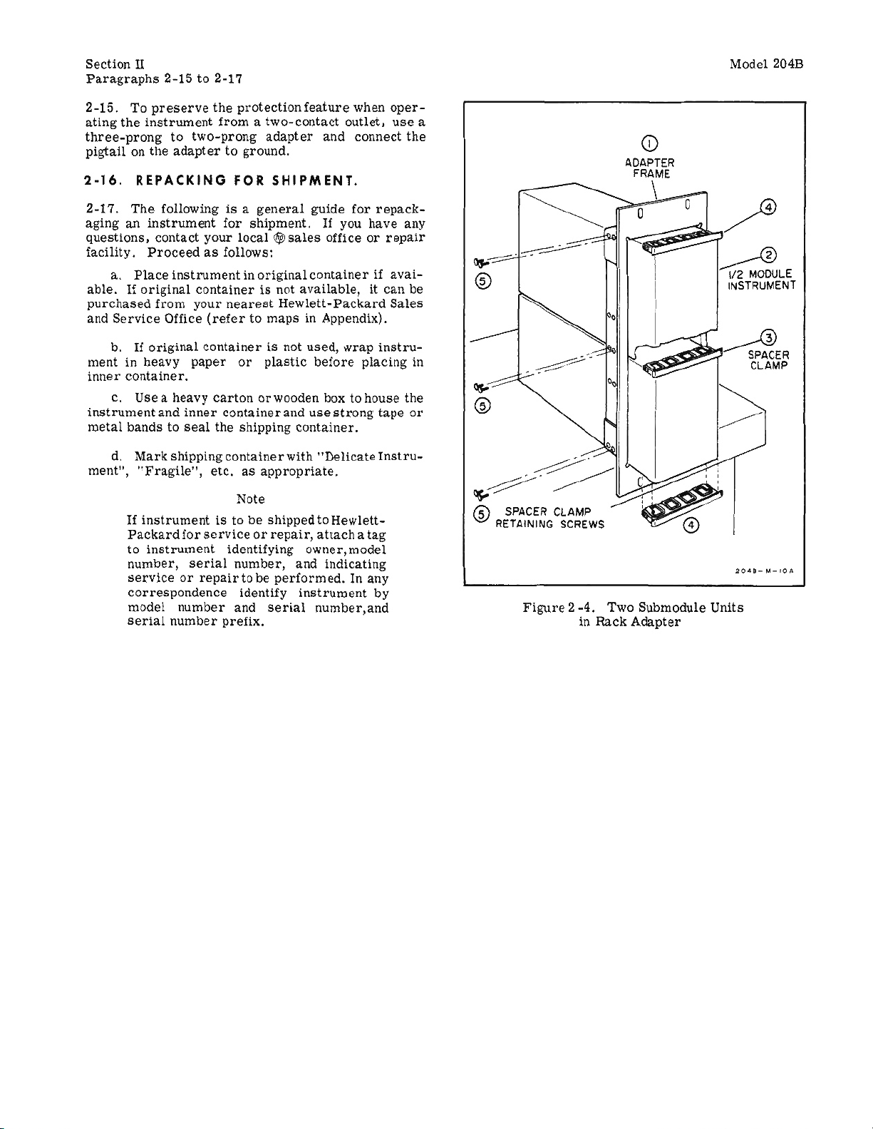
2-8. ADAPTER FRAME.
broken
as
sectionofthe
An
electrical
performance
for
incoming qual1ty-control
RACK/BENCH
The
Mode1204B1sshipped with
stand
remove
COMBIN1NG
The
useofthe
2-Z
the
divider
instrument
knobs.
described
after
checks.
attached.
To
adapt
the
plastic
procedure
CASE.
combining
unit which
suchasthe
unit,
the
oritcanberack
combining
for
liZ-module
Wlit.
thereforeitis
right
or
left
assembly.
inspection shouldbeperformed
ready
the
case
combining
upon
receipt
damage
etc.Ifdamageisapparent,
in
the
warrantyinthe
receipt;
These
INSTRUCTIONS.
Model204Bfor
feet identifiedin figure 5-3 by
given in
accepts
case
units.
divider
suchasscratched
"Claim
see
are
inspection.
for
useasa
paragraph
showninfigure
varying
Model 204B. Being a
case
mounted.
are
given graphicaUy in
The
latch
and
for
Damage in
rearofthis
paragraph
good
test
plastic
bench-type
rack
combinations
canbeused
Instructions
Model 204B
necessary
when
inspect
proce-
feet
mount-
5-13
2-1isa
to
installing
5-5
and
(c).
as
use
2-10.
2-11.
plied
There
placing
To
a
graph
2-12.
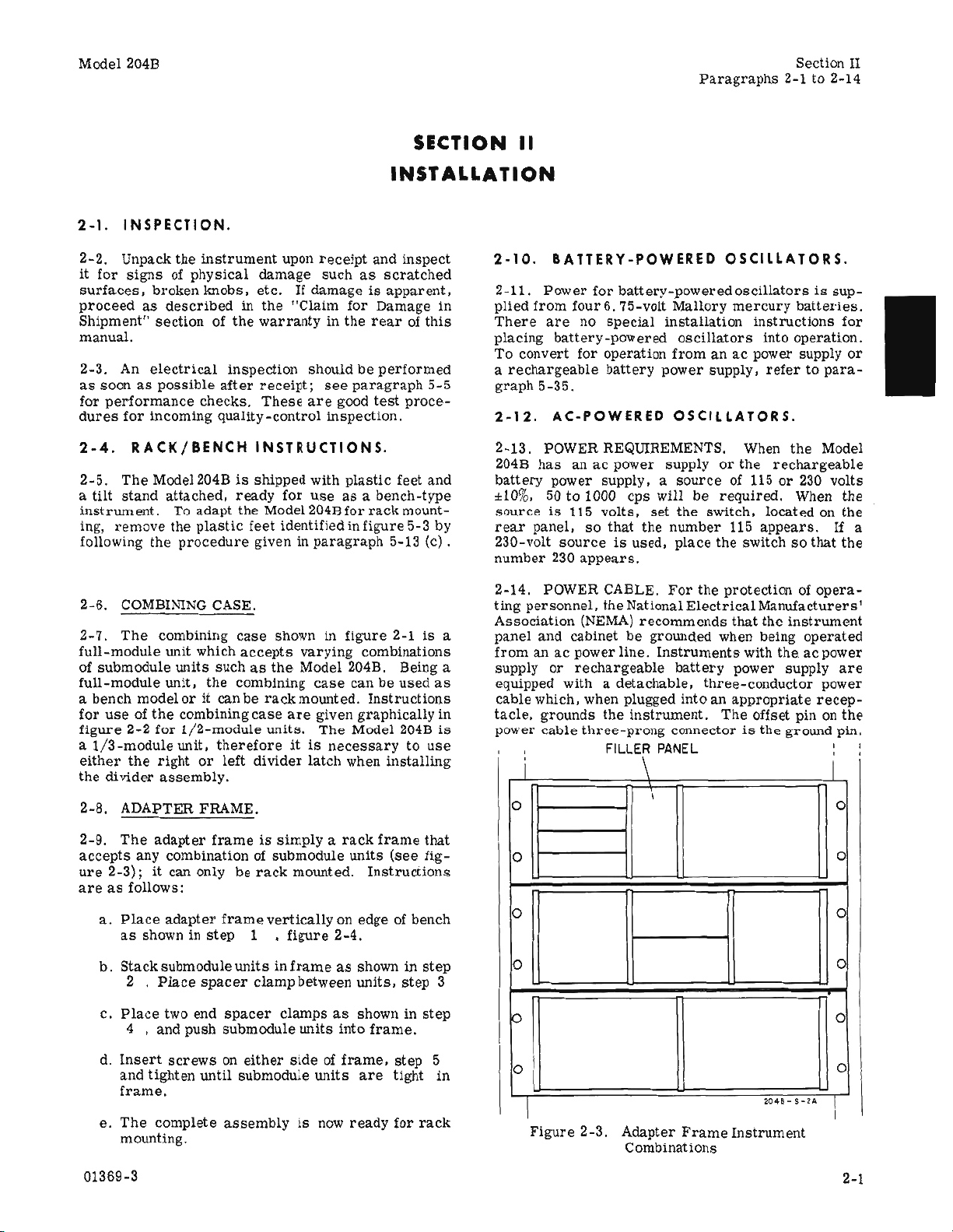
2-13. POWER REQUIREMENTS, When
2048
battery
::1:10%.50to
sourceis115
rear
230-volt
number
2-14. POWER CABLE.
ting
Association
panel
fromanac
supply
equipped with a
cable
tacle,
is
power
BATTERY-POWERED
Power
from
are
convert
rechargeable
5-35.
has
panel,
personnel,
and
which, when plugged
grounds
cable
for
four6.
no
special
battery-powered
for
operation
battery
AC-POWERED
anacpower supplyorthe
power
230
or
supply. a
IWO
volts.
so
that the
sourceisused,
appears.
the
(NEMA)
cabinet
power
rechargeable
the
three-prong
FILLER
i \
OSCILLATORS.
battery~poweredoscillators
7:i-volt
be
line.
detachable.
Mallory
installation
oscillators
fromanac
power
OSCILLATORS.
sourceof115or230
cps
wtIl
set
the
number
place
For
National
recommends
groWlded when being
Instruments
battery
intoanappropriate
instrument.
connectoristhe ground pin.
PANEL
mercury
instructions
power supply
supply.
be
required.
switch.
115
appears.
the switchsothat
the
protectionofopera-
Electrical
three-conductor
Manufacturers'
that
with
power supply
The
offset pin on
into
refertopara-
located on
the
is
sup-
batterles.
for
operation.
the
Model
rechargeable
volts
When the
the
If
the
instrument
operated
the
acpower
are
power
recep-
the
or
a
I
,
I (0
2-9.
The
adapter
accepts
ure
areasfollows:
01369-3
any combinationofsubmodule
2-3);itcan only
a.
Place
adapter
as
shown in
b.
Stacksubmoduleunitsinframeasshown in
2 .
Place
c.
Place
two end
4 • and push submodule
d.
Insert
and tighten
frame.
e.
The
complete
mounting.
frameissimplyarack
be
rack
frame
vertically
step
1 •
spacer
screwsoneither
until
clamp
spacer
8ubmodule Wlits
assemblyIsnow
mounted.
flgure
between
clampsasshown in
units
sideofframe,
frame
that
units
(see
fig-
Instructions
on edge of bench
2-4.
step
units,
step
step
into
frame.
step
5
are
tight
ready
for
rack
3
in
0
0
10
10
10
I
Figure
2-3. Adapter
Combinations
Frame
~.!_,_u
Instrument
I (
I (
I (
Ie
0
I
2-1
Page 6
Section
Paragraphs
2-15.
ating
three-prong
pigtailOnthe
2-16.
II
To
preserve
the
instrument
REPACKING
2-15to2-17
the
protection
fromatwo-contact
to
two-prong
adaptertogrOWld.
FOR
feature
adapter
SHIPMENT.
and
when
outlet.
cannect
oper-
use
the
Model 2045
a
CD
ADAPTER
FRAME
2-17.
aginganinstrument
questions.
facility.
able.Iforlglnai
purchased
and
ment in heavy
inner
instrument
metal
The
a.
Service
b.
container.
c.
bandstoseal
d.
ment",
If
Packard
to
number,
service
correspondence
model
serial
followingIsa
contact
Proceedasfollows:
Place
instrument
containerisnot
from
your
Office
If
original
paper
Usea
heavy
and
inner
Mark
shipping
"Fragile",
instrumentisto be
{or
Instrument
serial
or
repair
number
number
general
for
shipment.
your
local19sales
lnoriginal
nearest
(refertomaps
containerisnot
or
plasUc
cartonorwooden box to
container
the
shipping
container
etc.asappropriate.
Note
shippedtoHewlett-
serviceorrepair,
Identifying
number,
to be
identify
and
prefix.
serial
guide
If
officeorrepair
containerUavai-
available,itcan
Hewlett-Packard
in Appendix).
used.
before
and
use
container.
with
"Delicate
atracha
owner,model
and
performed.
indicating
instrument
number,and
for
you
.....
rap
strong
In any
repack-
have
Sales
instru-
placing
house
tape
Instru-
tag
by
any
be
in
the
or
=---
~.
~-~
@ SPACER CLAMP
RETAINING SCREWS
Figure
2
-4.
in
Two
Rack
o
Submodule
Adapter
o
...----@
liZ
MOOULE
INSTRUMENT
Units
4
2-2
01369-3
Page 7
Section
Figure
IJ]
3-1
Model 2048
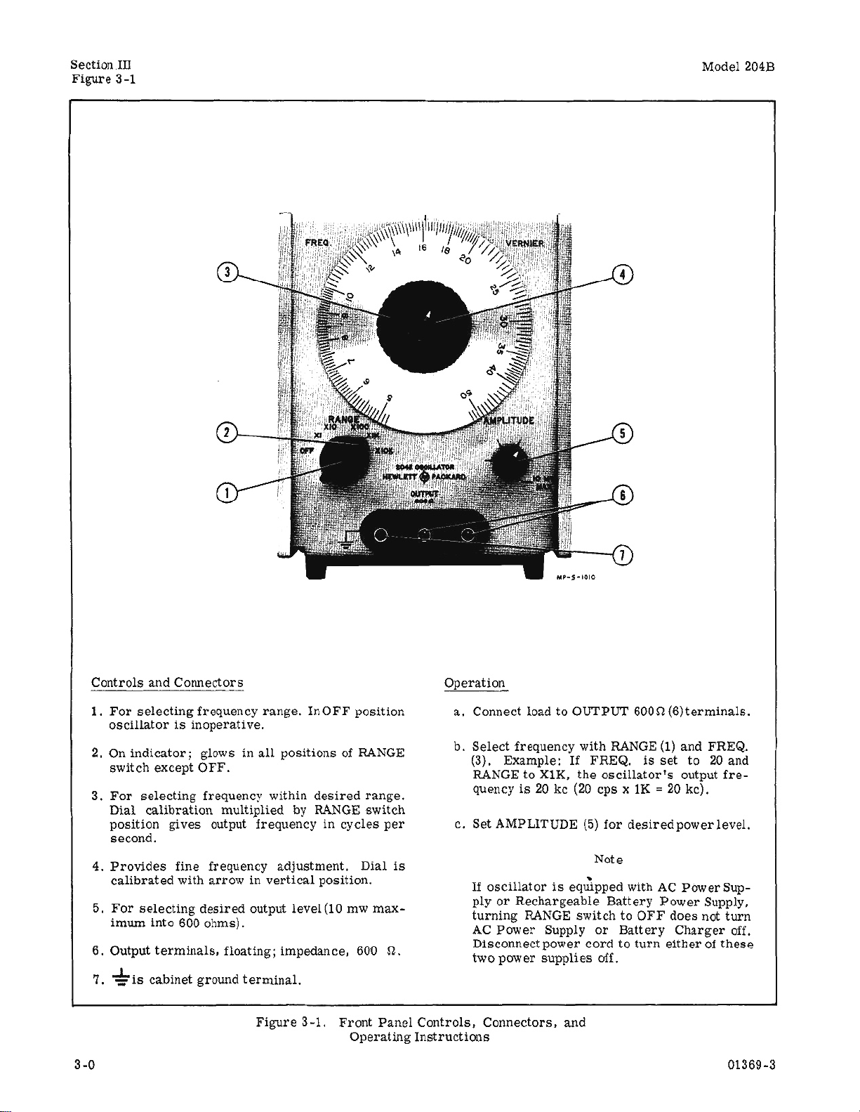
Controls and COlUlectors
1.
For
selecting
frequency
osclllatorisinoperative.
On
indicator;
2.
switch except
3.
For
selecting
Dial
position
calibration
OFF.
gives
second.
4.
5.
6. Output
7.
3
-0
Provides
calibrated
For
imum
~
is
fine frequency
with
selecting
desired
into 600 ohms).
terminals,
cabinet
groW1d
range.
glows in
all
frequency within
multiplied
InOFF
positions of RANGE
desired
by
RANGE
output frequency in
adjustment.
arrow
in verUcal position.
output level
(10
floating; impedance, 600 O.
terminal.
Figure
3-1.
Front
position
range.
switch
cycles
Dial
mw
max-
Panel
Operaling
per
is
Operation
a.
Connect loadtoOUTPUT
b.
Select
(3). Example:
RANGE to XIK.
quency1s20kc(20
c. Set AMPLITUDE
If
oscUlatoriseqtdpped with
ply
turning
AC
D1sconnect power
two
Controls,
Connectors,
Instructions
frequency with
or
Rechargeable
RANGE
Power
power
Supply
supplies
RANGE
If
FREQ.
the
oscillator's
cpsxlK=20
(5)
for
desired
Note
Battery
switchtoOFF
or
Battery
cordtolurn
off.
and
600Q(6)terminals.
(1)
and FREQ.
is
set
to
20
and
output
fre-
kc).
power level.
AC
Power
Power
does not
Charger
Sup-
Supply,
turn
off.
eitherofthese
Page 8
Model 2048
paragraphs
SectionIII
3-1 to
3-15
3·1.
INTRODUCTION.
3-2. The Model 204B has four
one output
signal in the
connector
5-cps
positioning the FREQ
trols.
AMPLITUDE
Output power level
control
(see
to 560-kc rangeisselected
.•
which has
A 115/230 volt switchison the
llalors
chargeable
3-3.
3-4.
given in figure
3-S.
3-6, To
lator, a blocking
are
equipped withanac
battery
PROCEDURE.
Operating
power supply.
instructions
3-1.
GENERAL
CONSIDERATlON
prevent
OPERATING
damage to
capacitor
operating
figure
3-1). A sinewave
RANGE, and VERNIER con-
is
controlled
atleast
rear
panel
power supplyorre-
for
the
Model 204B
S.
transistors
should be
with the output when connecting to a load
thereisa dc potential
Is used, Initial
capacitance-voltageproduct
volts.
exists
For
example, if a 20-voH potential
across
thp.
20v=200j..l.fv).
DO
NOT
ACROSS
OFF
LOADS
GROUND(.....)BY
current
load,
difference.
surge
usea10-j..I.f
When the
mustbelimited
less
than 200
capacitor
CAUTION
CONNECT THE OSCILLATOR
WHICH
ARE
REFERENCED
MORE
VOLTS;H1GHERVOLTAGESWILL BREAK
DOWN
3-7, When the Model 2048 is
RANGE
cillatortostabilize;
for
stabilization
sltions.1f FREQ. dialissweptattoo
put voltage fluctuations will
resistorisusedasthe
element).Ifsweep
stopped,
COMPONENT INSULATION.
switchissettoXl,
allow20seconds
only a few
when SWitching to
occur
variable
speedisdecreasedorsweeping
oscillator
output
will
initially
seconds
other
fastarate,
(Since a wlrewound
frequency
stabilizeatits
leveL
3-8, To obtain maximum amplitude
battery-powered
turn-on
effect may
during the
3-9. When
lopermit
causeasmuchasa1%change in amplitude
first20minutes
operating
Nickel-Cadmium) the
recharging (Nickel-Cadmium
maximum
rmS open
ohms.
to
paragraph
cadmium
3·10.
3-11.
for an
oscillator
circuitorless
For
batteries
OPERATION
BATTERIES.
ThereIsno
instrument
the
mercury
3-26,
osCillators,
battery
of operation.
from
batteries
output
becomes
than
battery
Charging
are
given in
WITH
change in the
in which the
wait20minutes
voltagetostabilize.
batteries
require
batteries
less
2.5
volts
replacement
Instructions
paragraph
RECHARGEABLE
operating
rechargeable
SECTION
OPERATION
controls
by the
a 40-db
usedinseries
THAN
turnedonand
are
stability
(Mercury
replacement
than 5. 0 volts
range.
whenoscl-
in the
oscil·
across
which
capacitor
microfarad-
difference
(lOj..l.f
±25
for
necessary
RANGE
determining
normal
from
after
This
only) when
rms
into 600
data,
refer
for
nickel~
3~16,
procedure
battery
and
by
are
to a
os-
po-
out-
or
or
III
supply has been
installed.
plypermitseitheracoperatiOnfor
(selected
sourcesorbattery
Battery
by switch
operation
operation
only (with
c08nected)isrequired
(0
£l
andisrecommended
104 F (400C),
3-12.
Is
ment and a
When the
removed
RANGE
from the
resistorisconnected
the power supply. The
operate
power
as
long
source,
as
The
put of the power supply,
oscillator
through the
prevents
connected
3-13,Itis
nected to a power
will
x
assure
operationisreqUired.
not
cord
3-14.
the
section
to maintain a constant
batteries.
battery
discharge
toapower
recommended that the
source
preventseIf-discharge
a fully
In
use, partiCUlarly when operating with the power
charged
disconnected.
When fully charged, the
oscillator
for apprOXimately
uousorintermltteJlt opesation provided they
temperatureof81
F ±10 .Ifthe
atedathigherorlower
is
reducedasthe
temperature
ed; approximatelY2B
imately
beyond
of supplying
20
hoursat-4 F
these
extremes
their
characteristic
voltage.
is
3-15.
adequate
in mind when
nal
obtainedifthe
a
be to avoid
direct
avoid placing the
surrounding
internal
The +1220Fto_4
for
temperatures
moderate
ambient
storing,
sunlight
temperature.
most
users,
operating
in
instrumentisleft in the sun, even with
temperature.
other
thanfor a
instrument
equipment might
THE HERMETICALLY SEALED CELLS
THESE BATTERIES
DAMAGED
REDUCED
OR
IF
EXPOSED
THEIR
TEMPERATURES, THIS DANGER INCREASES
UNDER PROLONGED CONDITIONS.
However, this power
115/230 vac
on
rear)
50
to 1000 cps power
for
portable
charger
at
temperatures
at
temperatures
switchisturned
oscillator
portion
across
charger
the
power
reSistor,
cordisconnectedtoa
placed
actsasa loadInplace
A diode in the output
when the
source,
power
whenever pOSSible,
of the
battery
Turn
battery
the
oscillator
whenever
batteries
40
batteries
temperatures
extrIemes
h0:-ors
at
12J F (50
(-20
C).
At
the
batteries
stable
0
F
temperature
however, keep
under
field cOJlditiOns.
excess
of 122 F
Good
transporting,
very
short
in a location where
excessively
CAUTION
MAY
BE PERl\1ANENTLY
LIFE
TO
DRASTICALLY
EXTREMELY
sup~
±-10%
applications,
power
cord
diJi'-
below 32 F
above
OFF, power
of the
instru-
the output of
wlll continueto
across
the
out~
of the
charge
rate
circuit
oscillatorisnot
cord
be con-
This
cells
and will
portable
OFF
when
wilt
hours
power
of
contin~
areata
are
operp
their
capacity
are
approach-
0
C)orapprox-
temperatures
are
not capable
discharge
range
these
limits
Inter~
are
easily
practice
or
operating
period.
raise
would
Also
the
IN
HIGH
is
in
01369-4
3-1
Page 9
Section III
Paragraphs
3-16
to 3-27
3-16. RECHARGING NICKEL-CADMIUM
BATTERIES.
3-17.
discharged
below 5. 0 volts
rms
much longer when
llator
sive
shorten
3-18.
connect power
batteries
hoursata
hoursata11milliampere
fully
be
20
charged,
time.
The
The
into
6000hms.
probably wHl not
discharge
their
To
recharge
will
discharged
turnedonfor
minutes.
the
The
llatorisOFF
CN!ase in
charging
mentisused
charge
current
adjustment
maximum of
charge.
used
high
3-19.
ture
ever,
Sho~ld
The
for
quick
rate
will
The
between
to obtain
be
ione
(27C:1:5.6
batteries
should be
when maximum
rms
open
circuitorless
The
batteries
this
point Is
meet
of
batteries
lile.
batteries,turnoscillatorOFF
cord
to a
be
fully
chargedinapproximately
5.5
milliampeN!
at the beginning.
use
alteraninitial
If
the
batteries
oscillator
charge
or
while the
circuit
canbeturnedonfor
rateisthe
operating;
time
will be
batteries
can
be
RI02
11
milliamperes
11
milliampere
charge
shorten
batterJes
+32
only. Repeated
battery
can
F to
+122
opthnum
atatemperature
C).
considered
oscillator
than2.5 volts
will not
reached
and
specifications.
may damage them
suitable
cllarge
power
charge
current
currentifthey
The
instrument
chargeofat
were
only
same
whether
therefore,
very
requiredifthe
are
being
increased
(refer
charge
to
to
with the
figure
provide
rate
life.
beochar&ed
at
an~
F (0 C to +50 C). How-
battery
life, techargl&g
of
80.6
CAUTION
THE FOUR NICKEL-CADMIUM BATTERIES
ARE
HERMETICALLY SEALED
DAMAGED
AT
(500C).
MENT
IF
CHARGED
A TEMPERATURE EXCEEDING 122 F
IF
THE CHARGE CURRENT ADJUST-
HAS
BEEN SET FOR A QUICK CHARGE
AT
AND
A FAST
RATE, PLACE THE INSTRUMENT
LOCATION WHERE THE
TE~PERATURE
(40 C),
3-20.
CYCLE-LIFE
DOES
OF
NOT EXCEED 104 F
NICKEL-CADMIUM
AMBIE~T
BATTERIES.
3-21. As
the
cycle-Hfe
the
batteries
h:.res
decrease
may
perature
3-22.
ing
charging
than the maximum
manufacturer,
3-23. The
the
225
hour
extremesIntemperatures
(complete
Is reduced.
wHi
Increase
the
resultifthe
for
the
cycle-lUe.
batteries
a prolonged
Batterycycle-Hfe
before
the
and
discharging
batteries
and
by not
cycle-ltfe
manufacturerer,on
milliampere-hour
charge
and
discharge
charge-discharge
Storageathigh
self-discharge
Permanent
are
storedata high
period.
canbe
extended by
are
completely
at a
ten·hour
rate
rate
overcharging.
of
the
batteries
an
endpoint of
capacity.
currentof22.5
are
rate
battery
whichisslower
specified
80%
Thisiswith a
as
fully
output
drops
operate
the
osci-
Exces-
or
and
source.
The
60
and
30
were
can
least
partially
dis-
useatany
the
osci-
little
In-
instru-
recharged
charge
5-11) to a
a quick
should
chargingata
tempera-
F
:1:10
CAN
BE
RA!E
IN
A
approached,
cycles)
tempera-
and
also
damage
tern-
recharg-
discharged,
by the
is
based,
ofthe
rated
ten-
milliam-
be
F
of
by
peres
..vlth
discharge
end voltage
on
every
in
excess
3-24. When
tor,
the
40
hour
if
they
cycle.
of 100
batteries
rate.
are
recharged
(t.
used
10
The
3-16.
3-25.
lowing a
battery
output
cuit
a quick
erate
connecting
charging
charging
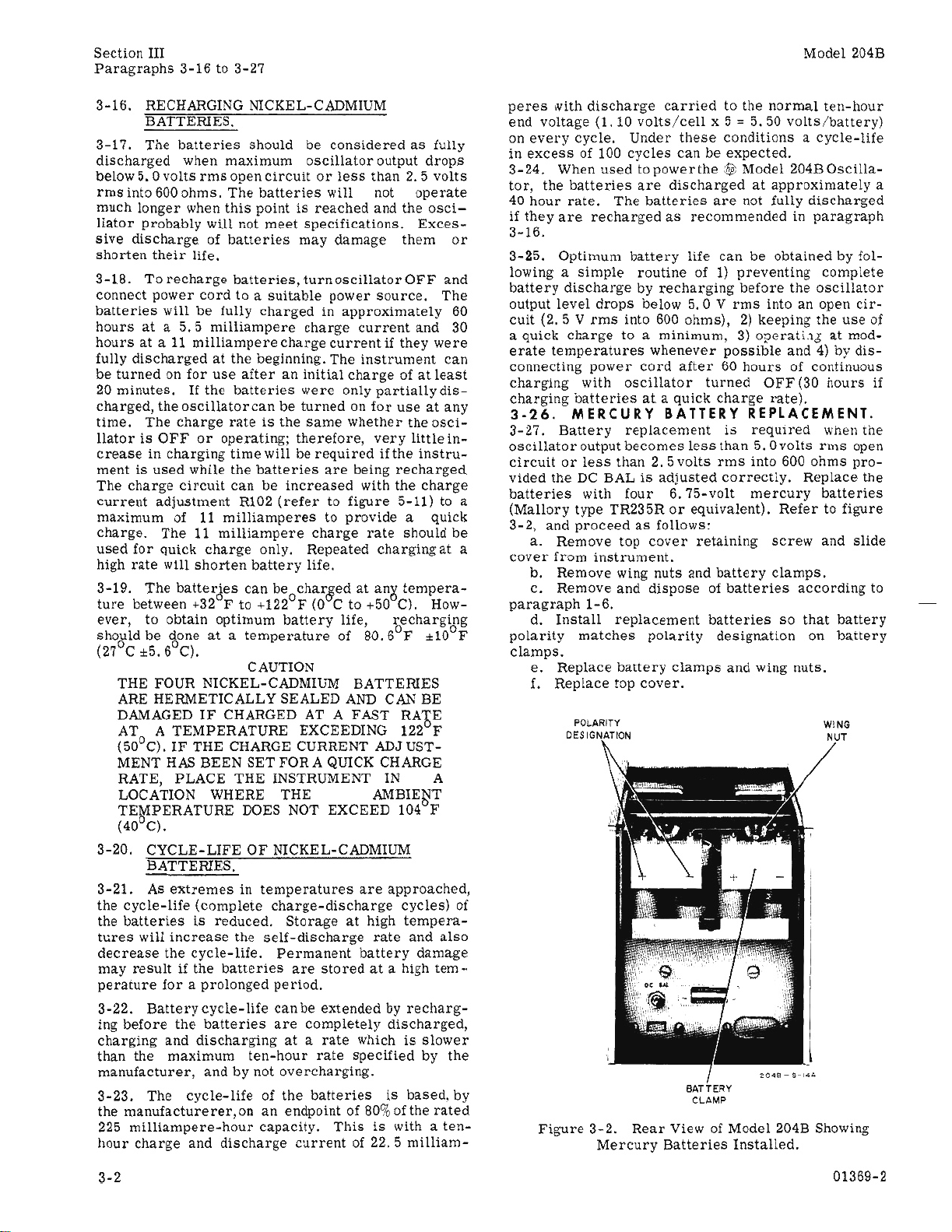
3-26.
3-27.
oscillator
circuitortess
vided the
batteries
(Mallory
3-2,
(2.5Vrms
a.
cover
Optimum
simple
dischargebyrecharging
level
drops
into 600 ohms),2)keeping the
charge
to a minimum,3)0?erati.1Jatmod-
temperatures
power
with
oscillator
batteriesata quick
MERCURY
Battery
output
than2.5
DC
BALisadjusted
with
type TR235Rorequivalent).
and
proceedasfollows:
Remove top
from
instrument.
b. Remove wing nuts
c.
Remove and
paragraph
d.
polarity
1-6.
Install
matches
replacement
clamps.
e.
Replace
£.
Replace top
D!SIGNATION
Figure
battery
'OLA"ITV
3-2.
Mercury
carried
volts/cet!
Under
cycles
canbeexpected.
topowerthe
are
dischargedatapproximately
batteries
as
battery
to the
x 5'"5.50
these
conditions a
$I;
Model
are
not fully
recommended
life
can
normal
be
routine of1)preventing
before
below
5.0Vrrns
whenever
cord
after
BATTERY
replacement
becomes
less
volts
turned
charge
rms
intoanopen
possible
60
hours
OFF
rate).
REPLACEMENT.
is
reqUIred
than
5.0
into 600
correctly.
four
6.75-volt
cover
retaining
and
mercury
battery
disposeofbatteries
batteries
polarity
clamps
designation
and wing
cover.
8ATTE"Y
ClJ;M?
Rear
View of Model 204B Showing
Batteries
Installed.
Model204B
ten-hour
volts!battery)
cycle-life
204BOscHla-
discharged
in pa.ragraph
obtained by fol-
complete
the
oscillator
cir-
use
and4)by
dis-
of continuous
(30
hours
whEen
the
volts
rms
open
ohms
pro-
Replace the
batteries
Refer
to figure
screw
and
slide
clamps.
according
so
that
battery
on
battery
nuts.
WING
'"
a
of
if
to
3-2
01369-2
Page 10

Model204B
SECTION IV
Paragraphs
Section
4-1to4-10
IV
4·1.
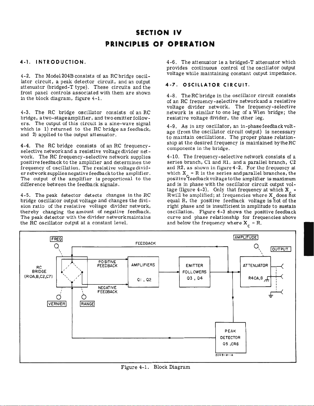
INTRODUCTION.
4-2.
The
Model204B
lator
circuit,apeak
attenuator
front
in
the
4-3.
bridge,atwo-stageampl1fier,
ers.
whichis1)
and2)appliedtothe
4-4.
selective
work.
positive
frequencyofoscillation.
er
networksupplies
The
difference
4-5.
bridge
sion
thereby
The
the
RC
(bridged-T
panel
controls
block
diagram,
The
He
The
output of
returned
The
RC
network
The
RC
feedbacktothe
output of
between
The
peak
oscillator
ratio
of
changing
peak
detector
oscillator
bridge
the
the
consists
detector
type).
associated
figure
bridge
frequency-selective
detector
oscillator
this
circuitisa
to
the
output
consists
andaresistive
amplifier
The
negative
amplifier
the
feedback
output
voltage
resistive
the
amountofnegative
with
the
outputata
PRINCIPLES OF
of an RC
circuit.
These
with
4-1.
consists
and two
RC
bridgeasfeedback,
attenuator.
of
an
voltage
and
resistive
feedbacktothe
is
proportional
signals.
detects
voltage
divider
changesinthe
and
network
constant
bridge
andanoutput
circuits
them
are
emitter
sine-wave
He
frequency-
divider
network
determines
voltagedivid-
amplifier.
changes
divider
level.
oscil-
and
the
shown
of an
HC
follow-
signal
net-
supplies
the
to
the
RC
the
divi-
network,
feedback,
maintains
OPERATION
4-6.
The
attenuatorisa
provides
voltage
4-7.
4-8.
of
anHefrequency-selective
voltage
networkissimilartoone
resistive
4-9.
age
to
maintain
shipatthe
componentsinthe
4-10.
series
and
which X = R in
posltive~eedback
and1sin
tage
Rw1llbeamplified;atfrequencies
equalR,the
right
oscillation.
curve
and
continuous
while
OSCILLATOR
The
RCbridge1nthe
divider
voltage
As
in any
(from
the
oscillations.
desired
The
frequency-selective
branch,
H2,
as
shown in
phase
(figure
phase
below
4-3).
andisinsufficientinamplitudetosustain
Figure
and
phase
the
maintaining
network.
divider,
oscillator,
oscUlator
bridge.
CI and
the
voltagetothe
with
Only
positive
relationship
frequency
bridged-T
controlofthe
constant
CIRCUIT.
oscillator
network
The
frequency-selective
legofa Wien
the
other
an
in-phase
circuit
frequencyismaintained
RI,
figure
series
the
oscillator
that
feedback
4-3
shows
where
output)isnecessary
The
proper
network
andaparallel
4-2.
For
and
parallel
amplifierismaximum
frequencyatwhich X =
voltage
the
for
Xc =
attenuator
oscillator
output
circuit
whereXdoes
frequencies
circuit
and a
bridge;
leg.
feedback
phase
consists
the
frequency
branches,
is
positive
R.
impedance.
consists
resistive
relation-
bytheRC
branch,
output
bot
feedback
which
output
the
volt-
of a
C2
at
the
vol-
Rot
of
the
above
RC
BRIDGE
(RIQA,B,C2,c11
IVE
Q
,
,
,
k
,
,
Ci
RNIERI
, ,
"'>1
, ,
"
'
,
,
0
I
RANGEl
POSITIIIE
FEEDBACK
NEGATIVE
FEEDBACK
AMPLIFIERS
Figure
FEEDBACK
QI
,02
4-1.
Block
FOLLOWERS
Diagram
EMITTER
03,04
PEAK
DETECTOR
05
,CR6
~O.I-~·'.
!AMPLITUDE
ATTENUATOR
R40A.B If,
Q,
I
,
,
!OUTPUT I
h-<
,
,
,
,
,
r-'--<
•
01369-2
4·1
Page 11
M.odel
204B
Paragraphs
Section IV
4-1to4-10
4·1.
attenuator
Iront
in the block
4-3.
bridge.atwo-stageamplil1er,
ers.
whichis1)
and
4-4.
selective
work.
positive
frequencyofoscillation.
er
The
difference
thereby
The
the
INTRODUCTION,
4-2.
The
Mode1204Bconsistsofan
lator
circuit.apeak
(bridged-T
panel
The
Re
The
output of
2)
appliedtothe
The
RC
networkandaresistive
The
feedbacktothe
networksupplies
output of
between
4-5,
The
peak
bridge
sion
oscillator
ratio
peak
Re
oscillator
of
changing
detector
detector
type).
controls
diagram,
returned
bridge
RC
the
associated
figure
bridge
frequency-selective
the
detector
oscillator
this
circuitisa
to
output
consists
amplifier
The
negativefeedback
amplifier
the
feedback
output voltage
resistive
the
amount of
with
the
output at a
the
detects
PRINCIPLES OF
RCbridge
circuit,
These
4-1.
and two
RC
attenuator.
resistive
is
voltage
divider
constant
circuits
with
them
consists
emitter
sine-wave
bridgeasfeedback,
of
an RC
voltage
network
and
determines
tothe
proportional
signals.
changesinthe
and
changes
divider
negative
network
level.
SECTION
oscil-
and
an output
and
the
are
shown
of an RC
follow-
signal
frequency-
divider
voltagedivid-
net-
supplies
the
amplifier.
to
the
He
the
divi-
network,
feedback.
maintains
IV
OPERATION
4-6.
The
attenuatorisa
provides
voltage while
4-7,
4-8.
ofanRe
voltage
network
resistive
4-9.
age
to
maintain
shipatthe
components in
4-10.
series
and R2,
which X
positive
andisin
tage
Rwiilbeamplified;atfrequencies
equal R, the
right
oscUlation.
curve
and
continuous
maintaining
OSCILLATOR
The
RCbridgeinthe
frequency-selective
divider
is
voltage
As in any
(from
the
The
branch,
as
""
<feedback
phase
(figure 4-3), Only
phase
and
below
the
network.
similartoone
divider,
oscillator,
oscillator
oscillations.
desired
the
bridge.
frequency-selective
C1
and
shown in
R in
the
voltagetothe
with
positive
andisinsufficient in
Figure
phase
relationship
frequency
bridged-T
controlofthe
constant output impedance.
CIRCUIT,
osc1llator
network
The
legofa Wien
the
other
an
in-phase
circuit
The
proper
frequencyismaintained
R1, and a
figure4-2.
series
the
4-3
and
parallel
amplifierismaximum
oscillator
that
frequency at which X
feedback voltageisliot of
shows
for
where
Xc
attenuator
oscillator
circuit
and a
frequency-selective
leg.
feedback
output)isnecessary
phase
network
parallel
For
amplitudetosustain
the
consistsofa
the
frequency at
branches.
circuit
where
positive
frequencies
=:
R.
consists
resistive
bridge;
relation-
bytheRC
branch,
output
X docs
feedback
which
output
the
volt-
the
vol-
the
above
C2
::
Rot
RC
BRIDGE
(RI0A,B,e2,C7)
IVE
IfREQI
Q
(j
RNIERI
\
,
,
,
,
,
,
.
,
,
,
,
,
,>1
,
,
,
b
RANGEl
I
POSITIVE
fEEDBACK
NEGATIVE
fEEOBACK
AMPLIFIERS
Figure
FEEOBACK
01,02
4-1.
Block
FOLLOWERS
Diagram
EMITTER
03,04
PEAK
DETECTOR
05
,
00'-11>-1'"
lAMPLITUDEI
ATTENUATOR
,eRG
0,
R40A,B
,
,
m
10UTPUT I
h--<
,
,
,
,
,
.,r-<
01369-2
4-1
Page 12

Section
Paragraphs
IV
L
r
1
1
1
1
1
1
1
1
1
1
1
1
1
,
'------
4-11to4-15
FREO.
9
,
----
"
RI
VERNIER
Model
2048
FEEDBACK
s-
r-
__
AMPLIFIER
ANO
EMITTER
CI
"
POSITIVE
FEEDBACK
FOLLOWERS
ATTENUATOR
O::U~TPUT
BRIDGED
TEE
s-
AMPLIFIER
NEGATIVE
FEEDBACK
01
"
C2
,
(j
s'
BIAS
VOLTAGE
l041-~·'"
'37
s'
Figure
The
4-11.
of
R3
to
maintain
level. The negative feedback
to
the dynamic
controlled by
the
diodes by
lator
the
change and
diodes, Diode conduction changes(seenasan
ance
amount of negative feedback.
oscillator
the
peak
on
CR4
Increased
the
amountofnegative feedbacktothe
amplifler.
in a
the
output
maintainedata constant14volts
4-12, Two
plifythe
followersQ3and
ward
condition
over
sampledbythe
bridged-T
4-13.
4-14.
resistive
andZIwhich
the
the
ctrcuit
change in
detector
decreaseinthe
distortion.
output changes,
output Signal exceeds -7 volts then, the
andCR5.
Impedance inZIof
Increasing
signal
amplifiers,
signaland apply ittocomplementary
biased
are
attenuator.
PEAK
The
peak
voltage
provide
oscillator
resistance
the
amount of
peak
convertsitto
the
bridge) I and
circuit
by CR2 and
conducting sHghtlytominimize
would
increasing
net input
decreases.
Q4.
The
peak
detector
DETECTOR.
detector
divider
negative feedback voltage
circuit
detector
the
Ql
The
emitter
CR3
oscillator
circuit
outputata constant
is
developed in
of
CR4 and CR5 which
forward
circuit.
the
peak
a new
results
If
the negative peak of
decrease
diode dynamic
the
negative feedback
tothe
The
oscillator
peak-to-peak,
and
Q2,
and
and
also
consists
4-2.
network
blas
If
detector
bias
level
in a differing
the
forward
resistance.
divider
emitterofthe
amplifier
(figure 5-9)
followers
underano-signal
circuit
coupledtothe
Simplified
consists
part
due
applied
the
osc11-
detects
for
the
imped-
bias
increases
results
and
thus
output
am-
emitter
are
for-
cross-
output
of Q5 and
is
to
is
is
Schematic
CR6.
put, and suppUes
to
control
resistive
4-15.
peakofthe
diodeCR6
of CR6 and
the
of
these
average
period
Diagram
This
circuit
bias
the
dynamlc
voltage
Peak
detector
output
breaks
C25
through C29
biastoCR4and
diodes.
the
bias
voltage
of one
cycle.
0.4
03
divider
signal.
down and
Capacitors
F,
F
0.2
V/
OJ
-
FP _ POSITIVE FEEDBACK
TO AMPLIFIER
F-
FEEDBACK
Figure
TO
4-3.
RC
samples
CR5, which
/'
NETWORK
RC Network
the
oscillator
proportionaltothe
resistanceofthe
network.
Q5
conducts only on
At 7 volts peak, breakdown
the
voltageatthe
decreases.
affects
C25 through C29
applied
FREQUENCY
/
-
-
/,
-
tothedlodes
Characteristics
circuit
output
diodesinthe
the
This
the
resistance
,
-
-
-
-
"-
""'-
RATIO-
PHASE
lOU-I-I!>
out-
signal
negative
junction
changes
act
over
LAG
-
PHASE
LEAD
----
to
the
4-2
Page 13

Model 2048
S-l.
INTROCUCTION.
5-2.
This
section
information
test
equipment,
dures,
in
the
which
5-3.
5-4.
checking
tabie
5-1.
canbesubstituted
for
and
a trOUbleshooting
section.
verify
REQUIREC
Test
Also
proper
equipment
performanceofthe
Equipment having
provides
the
Model
replacement
included
instrument
TEST
required
for
the
maintenance
2048
Oscillator.
and
adjustment
summary
are
performance
operation.
EQUIPMENT.
for
Model 204Bislisted
similar
equipment
are
maintaining
characteristics
listed.
SECTION V
MAINTENANCE
and
service
Required
proce-
included
checks
and
in
FOR
~
2046
@
o
,..,.
0
DIAL
ACCURACY
CHECK"",
.oon
Paragraphs
~
5232A/~32A
Section V
5-1to5-7
r0 I I0 0 I
-l-t'i<>r·--'====:'....:~..:J
I
"
I
I
I
I
I
I
I
I
I
....
..,T
~330
CID
5-5.
5-6.
2048isoperating
brated.
oraspart
the
has
5-7.
oscillator
PERFORMANCE
The
performance
These
following
been
DIAL ACCURACY CHECK.
a.
Connect
b.
Set Model
RANGE.., .
FREQ
AMPUTUDE.
VERNIER
Instrument
Oscilloscope
Distortion
AC
Voltmeter
DC
Voltmeter
Clip-On Range:
MilUammeter
Frequency
checks
of incoming quality
checksbesure
recently
frequency
outputasshown in
2048
...
, .
..
Type
Analyzer
Counter
checks
normally
may be
calibrated.
counter
controlsasfollows:
Passband:dcto
Measure
Frequency
Voltage Range: 1 mv to 5 volts
Accuracy:
Voltage Range:
Input impedance: at
Counting Range: 5
CHECKS.
verify
andisaccurately
used
control
the
figure
Required
Sensitivity:
Input
Impedance:
, ko
600 kc
negative
to
15
megohms
Accuracy:
Accuracy: 0.03%
that
after
maintenance
inspection.
test
equipment
and 600-ohm load
5-1.
MAX,
centered
Table
Characteristics
0.1
distortionto·40
Range: 5
:1%
voltages
volts
5 to
11
milliamperes
:3%
the
Model
cali-
In
used
to
x,
,
5-1
Required
600
kc
volts/cm
1 megohm
cps
to
Positive
from
least
cpsto600 kc
db
and
100 m
10
'T
Figure
c. Set frequency
Function..
SENSITIVITY. . . . . . . . . . .
DlSPLA
d. Counter should
e.
Set FREQ.
:t:l.5
milliseconds.
Test
Equipment
Waveform
Distortion
AC
voltage
DC
voltage
Charge
Frequency
current
measurements
5-1.
Test
Setup
for
Dial Accuracy
or
Distortion
counter
100 PERIODS AVERAGED
Y .
maximwn
read
dialto20, cOWlter should
Checks
controlsasfollows:
..
cOlmterclockwise
200
:t:6
milUse~onds.
read
Us. Recommended Model
checking
measurement
measurements
measurements
measurements
i5jJ
Mode1175A with
plug-in
i[j)
rEP
@ Model 412A
i[j)
rF}
Model 1753A
Model 33GB/C/D
Model 400H
Model 428A
Model 5232A15532A
3
50.0
I
01369-3
,-,
Page 14

Section V Model 2048
Paragraphs
5-6to5-9
f. Set FREQ.
:1:0.6
milliseconds.
g. Set
should
h. Repeat
ter
:1:0.06
QUENCY
j.
FREQ.
two.
column
Range
Switch Dial
XI00
XIOO
XI00
RANGEtoXI0and
read
should
milliseconds
L Set frequency counter function switch
(.1).
Complete check
dial
The
three.
XIX
XIX
XIX
dialto50, counter should
FREQ.
the
sameasstep
steps
read
5.00.:1:0.15
as
shown in
counter
Table
Freq.
e and f with
respectively.
reading
5-2
5 500
20
50
5 5 kc
20
50
f.
milliseconds
by
setting
table
should be
Dial Accuracy
2000 cps
5000
20
50
dialto5,
RANGE
RANGE
5-2,
cps
:I:
:I:
cps
% 150
•
kc
•
kc•1.5
read
20. 0
counter
atXlO.
columns one and
15
ao
150
600
Coun-
and
to
switch and
as
shown in
cps
cps
cps
cps
cps
kc
2.00
FRE-
~2048
@
o
"""
T
Figure
5-9.
a.
to
oscillator
5-2.
DISTORTION CHECK.
Connect
outputasshowninfigure
4j!400H
D
~oon
0
Test
and Output Voltage Check
distortion
Setup
,-{
~
for
Frequency
analyzer
and aOO-ohm load
0
t04.-S-U
Response
5-1.
XI0K
XI0K
XI0K
5-8. FREQUENCY RESPONSE
VOLTAGE CHECK.
a.
Connectacvoltmeter
lator
output:asshown in
b. Set Model 204B
to
25.
c. Adjust AMPUTUDE
voltmeter.
d. Sweep FREQ. dial by handtoread
is
swept,
than %0.075 volts.
e, Set Model 204B
f. Set FREQ. dial
g. Complete check with
untested
voltmeter
position while
5
20
50
and
figure
RANGEtoXl
reading
RANGEtoXlO.
to
5 and
RANGE
repeating
50
kc
200
kc
500 kc
AND
aOO-ohm
5-2.
for
should nct
repeat
1. 5 kc
•
•
•
OUTPUT
and FREQ.
2.5
volt reading
step
switch
step
d.
6
kc
15
kc
loadtooscil-
dial
50. As
vary
d.
settoeach
dial
more
on
b. Set Model 204B
RANGE
FREQ .
AMPUTUDE.
c.
Set
distortion
FREQUENCY RANGE.
INPUT .
FUNCTION .
METER
d. On
(1)
(2) Set FUNCTION
(3) Adjust TINE andCOARSE frequency
(4)
e.
Meter
range.
RANGE
distortion
Adjust INPUT SENSITIVITY for full
reading
and BALANCE
frequency
necessarytomonitor
Readjust
reading
controlsasfollows;
.
analyzer
analyzer:
(1. 0).
(1
kc); switch METER
controls
should be
controlsasfollows:
.
to
DISTORTION.
controlfor
until
less
XI00
10
(I
MAX.
XI00
SET LEVEL
100%
dipatfundamental
dip.
absolute
than 1. 0 on
RANGE
dipislocated
kc)
A.
scale
controls
as
the
1%
5-2
Page 15

Model204B
I
I /
1--/
Paragraphs
Section V
5-10to5-15
5-10.
5-11. When
ploded view,
5-12. COVER REMOVAL.
5-13.
ment
figure
pushing foot
which
a.
Remove
b.
Slide
c.
Slide
d.
REPAIR.
Remove
5-3,
and
top
Lift
foot
repairing
figure
5-4,asan
covers
requires
proceed
top
covertorear,
rear
release.
assemblytoremove.
priortoany checkoradjust-
powertobe
cover
foot
assembly
the
Model 204B,
aidtoidentifying
as follows:
screw.
and
Figure
use
the
applied.
li!ttoremove.
toward
Refer
side
5-3.
ex-
parts.
whlle
to
zeu-r-I'
Cover
Removal
e. Remove bottom
f. Slide bottom
g. Remove
h.
To
the
orderofstepsathrough
5-14.
5-15.
204B
the
large
soldering
pressuretothe
soldering
addition to the aboveinformation, the following should
be
SERVIClKG ETCHED CIRCUIT BOARDS.
The
require
conductor
components,
observed.
side
replace
etched
that the
side
iron
tip
parttoliltitfrom
tip
such
cover
screw
and
liit
covertorear
cover
screws
covers
circuit
of the
suchaspotentiometers,
from
as
and
boards
soldering
board
lead to lead whlle applying
Ungar *855
and
and
foot
assembly,
g.
usedinthe
iron
when
the
3/4
11ft
side
tip
servicing.
boardoruse
in. Cup Tip. In
be
tnt
stand.
to
remove.
covers.
reverse
applied to
rotate
Model
For
the
a
01369-2
5-3
Page 16

Section V
Paragraphs
5-16to5-24
Model 2MB
a.
Do
not apply
b,
Apply heat to component leadonconductor
of
board,
and
c, Use a toothpick
holes.
d,
Solder
ductor
5-16.
5-17. To
a thorough
or
condition which
vlsuallnspection
block
mary.
troubleshooting
tobetaken
taken in the
5·18,
side.
TROUBLESHOOTING,
locate
visual
loose
components, loose connections of any
diagram,
table 5-3,adaids
for
order
ADJUSTMENT
excessive
remove
replacement
trouble in
inspection. Look
suggestsasource
does not
figure
summary
various
given.
PROCEDURES.
5-19.
5-20.
and -13 volts, but may
line voltageisvaried
voltages should
AC
POWER SUPPLY CHECKS.
Theacpower supply voltages
remain
leadwith a
or
wooden
components from
the
reveal
4-1,
and troubleshooting
for
isolating
lists
troubles;
AND
vary
from12to
from
103,5
with the12to
Figure
heat,
straight
spanter
Mode1204B,
the trouble,
indicationof and
the action should be
5-4.
upward pull ,
start
for
burned-out
of
trouble.
the
trouble.
to
the
use
action
CALIBRATION
are
typically
13.5
volts.
to 126. 5 volts, supply
13,5
volt
Model 204B, Exploded View
5-21. Ripple voltage in theacpowersupply should be
side
clean
con-
with
less
than 2 mv, To check
essary
the junctton of RI0A
as
5-22. When
check
formed,
5·23,
to connect a
the
line voltageisvaried
trouble
CR15
and
adjust
BATTERY CHARGER CURRENT
ADJUSTMENT.
other
If
the
sum-
The
+13
As
limit.
a
5-24,
for
life,
provide a
current
5·25.
current
one input lead of
The
haHerychirger
5.5
:1:0.5milliamperestoprovide
Charge
quick
to not
Use
the
adjust
a.
Remove top
b.
Connect power
c.
Turn
oscillator
d. Attach
5-11.1
e.
Set RI02
CR16
DC
current
charge
more
following
RI02
current
battery
fo,r
ripple
wire
from
and
StD,
from
occurs,
first.
BAL
control
currentissetatthe factory
adjustment
by
than11milliamperes.
procedure
for
quick
cover
from
cordtoa power
OFF,
probeofclip-on
charger
the
desired
voltage. itisnec-
circuit
Measure
103, 5 to
in
theacpower supply
If
any
(paragraph
maximum
RI02
increasing
charge
oscillator
circuit,
charge
ground
ripple
repair
the charging
to
operation.
source.
m11li;lmmeter to
current.
rtf,)
voltage
126,5
volts.
is
5.26).
battery
canbeset
set
charge
chassis.
(See
figure
to
per-
to
5-4
Page 17

Model204B
Paragraphs
Section V
5-25to5-30
Note
Do
not
charge
amperes
f. Replace top
5-26.
5-27. When the
properly
at the
ceedasfollows:
(With the optional
connect
the junction of
volt reading.Ifnecessary,
for
.zero
5-28. DISTORTION ADJUSTMENT.
output
trol
DC
oscillator
a.
Connect a
b. Set AMPLITUDE to
c.
Adjust
proper
volts, check
a.
terminals.
b. USinganAC
voltage between
exceed11milUamperes.
current
BAL ADJUSTMENT.
adjusted
DC
voltmeter
Ll
DC
range of R15.IfDC
Connect a 600-ohm load
exceeding11milli-
will
shorten
cover.
DC
BAL
there
output.Ifdc Voltageispresent,
DC
voltmeter
Rechargeable
and
SALonrearofinstrument
power
voltmeter,
circuit
battery
control
shouldbenodc voltage
between floating ground and
CI02.)
MAX.
change the value of
supply
ground and
to
Battery
SAL
measure
life.
Rl5
oscillator
will not
for
proper
across
Table
A
(rear
panel)
present
pro-
output.
Power
Supply,
forazero
R18
adjust
voltages.
the
oscillator
the
gain con-
armofpoten-
5-3.
Troubleshooting
tiometer
mv
resistance
is
load
mum reading, Reading should be
to
5~29.
5-30.
performed,
to frequency
oscillator
R36. Voltage should be between90and 140
rms
on aU
ranges.
c. Set Model 204B
d. Connect
e.
a.
of R34;iflow,
RANGE
FREQ"
VERNIER
AMPLITUDE
on
oscillator
Measure
Do
only) and disconnect
from
measurements.
FREQUENCY CALIBRATION ADJUSTMENTS.
Frequency
Connect frequency
Swnmary
...
..
..
distortion
distortion,
not
use
oscillator
onlyifnecessary,
sensitive
outputasshown in figure 5-1.
If
voltageishigh,
decrease
controlsasfollows:
analyzer
output
terminals.
and
Note
coaxial
calibration
cables
all
other
when making
adjustments
after
components.
counter
resistance.
XI00
10(1kc)
centered
..
MAX.
across
adjust
(use twin lead
R36
less
than
equipment
distortion
repairs
and 600-ohm load to
increase
600-ohm
for
mini-
1%.
should be
are
made
Indication
No
output
greater
measured
Cl02
with
No
output
output
No
outputononeormore
Output
distorted
If
all
If
all
signal;dcvoltageatoutput
than±lvolt (de voltage
at junction ofLland
on Option02PowerSupply
Rechargeable
signal;
(zero
volts)
amplitude
ranges
ranges
are
are
Batteries)
proper
net
correct
affected
NOT
affected
dc voltage
ranges
and/or
at
Action
Check
Check
Check
power-supply
Q3, Q4, CR2, and
(refertoschematic
Ql,
Q2, and CRI
(refertoschematic
Check
power-supply
Check Wien
Check
Check
Check
Check components connected
RANGE switch
If
inoperative
Check components connected
RANGE
Check
Check components In
for
for
Xl
Check peak
per
atic
Check for
respectively
Check components connected
affected
bridge
Ql
andQ2for
peak
detector
RANGE
switchisin
power-supply
proper
tolerances).
position, check R24, R4, C2A, RIOA, RI0B,
detector
operation.
diagram.
incorrect
ranae
voltages
voltages
components
correct
circuit
switch contacts
is
inoperative
positionisXl,
voltages
upper
value :I:percentoftolerance
For
circuit
Refer
Be
sure
voltagesatQ3, Q4, Q2, and Ql
(+13
and -13 volts)
CR3
for
correct
diagram)
for
correctdcvoltages
diagram)
(+13
and -13 volts)
voltages
CR4, CR5, and CR6)
(Q5,
to
Wien
position.
check
to
peak
inoperative
(+13
and -13 volts)
and lower
example: When
(Q5. CR4, CR5, and CR6,
towaveforms
CR6
breaks
to
peak
dc voltages
bridge
detector
position.
detector
position when
For
C2A
and C7A.
legs
of Wien
(refertotable
RANGE
and voltages in
down at 7 volts
example:
circuit
-
bridge
switchisin
RIl,
circuit
when
-
6-1
andC7A.
£orpro-
schem-
peale
in
01369-4
5-5
Page 18

Section V
Paragraphs
5-31 to
5-35
Model204B
b. Set Model 204B RANGE to XI00,
centerofits
clockwise
c.
Set
d. Lock FREQ.
socket
serts
into
e.
Loosen
ure
5-5a,
a5.6-kc
L
Tighten
locking
g. Set FREQ. to 5 (500
locking
h.
Loosen
by
turning
i.
Tighten
locking
j.
Repeat
within
adjustC8(figure
(figure 5-4) to obtain a 560-kc output.
change the
k.
m.
n.
within
approximately
Set
Set
Check
steps
All
:1:3%.
5-31.
5-32.
5-33,
orderitby
For
CAM
If
easier
range,
poSition.
FREQ. to56(5.6
set
screw
threaded
potentiometer
and
adjust
output.
pot
screw.
screw.
screw.
dial
camtoobtaina500-cps
dial
stepscthroughiuntil
RANGE
FREQ.
value
gain
a and b of
frequencies
and AMPLITUDE to
kc).
dial
shaft
(dial
shaft
hole
on topofdial
potbyturning
shaft
locknut,
shaft
shaft
locknut and
±1%.
to XI0K, FREQ. to 5 (50 kc),
5-6) to
to
56
of C14
control
paragraph
obtain
(560
Note
across
with a
locking
(pot)
and
cps)
and
locknut
for
voltage
and
a 50-kc outpuL
kc),
proper
according
5-28.
the band should
shaft
pot
output.
and
REPLACEMENT PROCEDURES,
CABLE REPLACEMENT.
it
is
necessary
rEjJ
Stock No. 8160-0003 and
access
to the
to
replace
cams,
remove
VERNtERto
maximum
number
screw)
shaft
locknut,
armtoobtain
loosen
tighten
adjust
loosendialshaft
frequencies
adjust
If
range
the
description.
8-32
which
housing.
dial
shaft
dial
shaft
dial
necessary,
of C15.
to
cam
cable,
the
screws
in-
fig-
cam
are
and
C15
be
holding the
the two
guide,
a.
b. USingahex
remove
c. Remove
d. On
inches
e.
bolt
shownInfigure
L With
boltasshown,
g.
second
terminal
h.
use
the
cams,
cam.
Aand
I.
in
cable
not
overtighten
j.
(paragraph
5-34.
5-35.
RI0A and B,itis
For
holding the
swing the twa
as
a guide, and
a.
instruments
counterweight
powersupplyandcircuit
assemblies
and
proceedasfollows:
Orient
from
Slide
so
Slide
Orientate
(The
B; the
Tighten
Perform
easier
Position
camsasshown in
both
cable
replacement
the end.
replacement
that
cableisorientated
mark
cable
terminal
boltasshown in
figure
and
install
shorter
longer
both
and allow
5-29).
FREQUENCY
REPLACEMENT.
To
replace
access
power
assemblies
have
shownInfigure
to the
socket
terminal
terminal
5-5a,
on the
install
ends
bolt
the
as
a gUide. SUde the
the
cable
length
terminal
the
cable.
Frequency
the
necessary'toremove
supply
proceedasfollows:
camsasshown in
aluminum
side.
wrench
bolts.
bolts
from
cable,
lower
terminal
approximately
so
figure
camsas
second
length
dialtocover
POTENTIOMETER
frequency
to the
placeamark
cable
left
cableincenterofterminal
boltondial
that
cableisorientated
5-5a,
showninfigure
terminal
should
should
pass
boltstoremove
Calibration
cams,
and
circuit
to the
cams
5-5.
board,
Use
figure
and
cable.
through
to
detail,
its
potentiometer
remove
side.
figure
Other
then
figure
5-5a.
3/8-inch
one
terminal
1/4
inch
upper
left
cable
bolt
on the pot
pass
over
overD,B,
full
range.
Adjustments
the
the
board,
Use
figure
5-5a.
which have the
instruments
swing
5-5asa
wrench,
6-7/8
terminal
bolt
cam.
through
detail
5-5band
onto the
points
and C .
all
slack
(pot),
pot
cam.
screws
then
Some
as
to
.
Do
5-5
TERMINAL
BOLT
LENGTH
5-6
LOtlO
"r
>/6
MARK
$HQUI.D
Itl
CENTEIl
,","'
LEtlGTH
,y)
_
V
B!
Figure
5-5.
Cams
and
COUNTEIlWEIO"T
PA"~I.
BIJSI1INQ
POT
SHAFT
~T
A~M
C~BLE
TERMINAL
POT
CAM
DIAL
$HAFT
LOCKNUT
DIAl-
CAM
Cable
Relationship
NUT
lOCKNUT
BOLT
I©
0
©
0
__
._
SHO~T
CABlE
lE.NQTH
·
..
····t~~U~1ILE
~C
..
-C-H
CiolASSI$
'"
""
""
OIAL
,
..
Page 19

Model 204B
Paragraphs
Section V
5-36 to 5-37
have
plastic
weight.
following
plastic
cams
Ignore
procedure
cams.
b. Loosen pot
c. Using a hex
bolt on
cable
tion of
use
cable
over
over
imately
pd
cam
slips
off
cam.
d. Slide
pot:
cableisshorter
e, Remove
I.
Remove
g.
Orient
the
figureasa guidetohelp you
properly.
three
pot.
the
(The
pointsAand
points
h.
L
D. B,
Turn
Install
cable
1/2
turntoremove
counterweight and
nut, COWlterweight
as
showninfigure
j.
Align pot
k. Remove aU
terminal
bolt clockwise. Do not
which do
any
references
when
shaft
socket
counterclockwise
cam
off
screws
and
cams
not
your
locknut and
wrench,
pot:
arm.
than
the
holding
install
as
showninfigure
require
to
counterweight in
instrument
panel
turn
1/2
Note
other.
pot:tochassis.
replacement.
string
shorter
B;
the
and
terminal
C.)
cable
longer
length should
bolt clockwise
some
slackinthe
length should
tighten
is
keyed and shouldbepositioned
5-5.
(omit if no cOWlterweight).
camtothe
slack
same
planeasdial
in cable by tm-ning
overtighten
.........._10
Figure5-6.
a cOWlter-
has
bushing nut.
cable
terminal
turn
or
that
one
5-5b
the
approx-
cable.
panel
bushing
cam.
cable.
10PT10~
Range Swit ch
the
until
sec-
and
cam
pass
pass
cable
~OWE~
,v_ny
020.cy\
m.
n.
paragraph
5-36.
5-37.
rP)
figure
RANGE
To
Stock No. 204B-95D,
5-4,
a.
Remove
b.
c. Remove
the
RANGE switchtofront paneL
d.Inorder
necessarytoslide
edgeofchassis;
e.
ure
5-6asa guide
I.
Install
removedinstep
g.
is
adjacenttoOFF
h.
i.
and
Perform
DC
Detail
With
cams
aligned, tighten pot shaft locknut.
Perform
Frequency
5-29.
SWITCH ASSEMBLY REPLACEMENT.
aidinreplacing
and
range
oscillator
Remove RANGE
indicator
to
remove
switch away
clip
Solder
leadstoreplacement
for
switchasshown in
c.
Replace
indicator
position.
Replace
switch knob.
Frequency
BAL
Adjustment,
Calibration
the
RANGE switch
refer
switch
switch
detail.
covers
decal
leads
to
(see
knob.
and
the
the
from
from
leadsatswitch
correct
lead
figure
decalsothat
Calibration
Paragraphs
".,-,
...
Adjustments,
assembly
exploded view.
figure
paragraph
5-6.
5-12).
nut whichholds
switch, it
panel and lift
terminals.
switch using fig-
connections,
5-4 using nut
black
portion
Adjustments
5-29 and 5-26.
Is
to
01369-4
5-7
Page 20

Section V
Paragraphs
5-38 to
5-46
Model
2048
5-38.
5-39.
battery-powered
mercury
~ Stock
Supply
Refer
BATTERY-PACK POWER SUPPLY.
To
convert
batteries,
No.
according
to
paragraph
an
Model 204B
obtainastandard
204B-64B.
to
Instructions
AC-powered
for
Install
3-26
Battery-Pack
for
battery
instructions.
5-40.
5-41. To
battery-powered
power, obtain
204B-llA.
AC-Operated
Included
5-42.
5-43.
replace
Supply.
nickel-cadmium
operation
115/230 volt
50 to 1000
supply
poweredora
ation from a
obtain
llC.
accordingtoinstructions
5-44. After
been
output voltage level.
open
llator
cedureinparagraph
AC POWER SUPPLY.
convertabattery-powered
Model 204B
AC
Power
(Refertofigures
Power
with
kit.
RECHARGEABLE BATTERY POWER SUPPLY.
The
Rechargeable
the
standard
This
supply
Supply
Battery
contains
batteries
and a
charge
(selected
cps
power
is
approximately3watts.
circuit
by switch on
line.
battery-powered
reChargeable
Rechargeable
Install
Rechargeable
Battery
for
Supply Kit, <§lStock
5-8 and
accordingtoinstructions
Battery
Packorthe
four
which
which
Power
Model 204B for
battery
Kit,
Battery
included with kit.
installed,
circuit
OFF
and
Rechargeable
turn
oscillator
(2.5Vrms
recharge
Battery
on and check
If
level
into 600 ohms),
batteries
3-16.
CAUTION
BE SURE TO PLACE 115/230 VOLT
LINE SWITCH (SlOl)
IN
POSITION BEFORE CONNECTING
POWER CORD TO A POWER SOURCE.
(SEE PARAGRAPH
5-45. REPLACEMENT
2-12.)
OF
RECHARGEABLE
BATTERIES.
5-46. When
ment,
disconnect
The
following
a.
Disconnect
side
and
b. Remove
rechargeable
power
cord
batteries
and
procedureisrecommended:
power
cord
covers.
six
screws
holding
turn
and
or
reChargeable
operation
Battery
from
Pack,
Power
Included with
kit.
replacement
or
rechargeable
operation
Power
6.25
permit
operates
rear
5-12.)
Supply can
AC
volt
panel
from
Install
Power
sealed
portable
from
S10l)
input to this power
To
convert
an
oper-
r$}J
Stock
Power
power
Power
supply,
No.
2048-
Supply
Supply
maximum
is
below5.0 V
follOWing the
turn
rms
osci-
pro-
PROPER
require
oscillator
remove
rear
top, bottom
panel in
replace-
OFF.
place.
AC
No.
AC
has
RE:AR
SIDE
SCREWS
POLARITY
DESIGNATION
REAR
SCREWS
SIDE
a
REAR
PANEL
Figure
5-7.
Rear
View of
Battery-Powered
REAR
SCREWS
2048-S-11A
PANEL
Model 204B
d.
Loosen two
in
place.
e. Slide
f.
Unsolder
black, and
g.
Remove two
washerS
h.
Remove
power
violet
from
screws
supply out of
resistor
wires
cap
battery
and
discard
RI06
from
nuts
holder
holding
(4.7
batteries
and
and
rear
old
batteries.
oscillator
oscillator
ohms),
(see
figure
screws
panel.
board
chassis.
red/orange
5-9) .
with
fiber
CAUTION
DO
NOT DISPOSE
BURNING,
AS
OF
BATTERIES BY
THEY EXPLODE
IF
INCINERATED.
i.
Place
observing
four
battery
new
polarity
batteries
as
indicatedinfigure
in
instrument
5-9.
c. Remove four
circuit
boardinplace.
5-6
screws
holding
battery
charger
j.
fiber
Replace
washers.
battery
holder
cap
nuts,
screws,
01369-3
and
Page 21

Model204B
Section V
Figure
5-8
VIOLET BLACK
RED/ORANGE
AC
SUPPLY
115/230
SWITCH
CHASSIS
AC
POWER
CONNECTOR
2048-5-184
k.
Solder
R106,
wirestobatteries.
m.
Slide
power
fasten
Wires)
orange
n.
p.
ground
BTl04.
ground
with
screws
Tighten
Check
screws
voltage
and bottom
(See
figure
mustbenegative
wire)
mustbepositive
{black
wireonbottom
01369-4
red/orange,
(See
figure
supply into
5-9.)
oscillator
removedinsteps
loosenedinstep
and
polarity
terminals
5-9.)
on
batteries
TerminalonBTlOl
and
,terminalonBTl04
with
terminalsofBTI02
black,
band
d.
between
respect
Figure
and
chassis
c.
floating
BTI01
to floating
5-8.
violet
and
and
(violet
(red/
and
AC
Power
BTI03).
approximately
either
less
installed.
satisfied,
oscillator
open
OFF
in
Supply
Measured
13
terminal
than
1 volt),
q.
When conditions of
turn
oscillator
output
r.
If
maximum
circuit
and
paragraph
5.
recharge
Replace
is
less
3-16.
top, bottom and
voltageateither
volts.
or
measured
If
batteries
previous
on and
voltage.
oscillator
than
5.0Vrms,
batteries
terminal
polarityisreversed
voltageislow (usually
have not
been
steps
measure
properly
have
maximum
output voltage into an
turn
by following the
side
covers.
oscillator
procedure
will be
at
been
5-9
Page 22

Section
Figure
V
5-9
Model
2048
RI08
"",rOHIIlS
JIOI
BTIO""
BTI03
8TI02
TOP
+
+
+"
~~n~N
TO
SIB
.e<
I 8ATTEIIY
SU(
'0
FLOATINO
'0
CHARGE
CIRCUIT
+
TO
SID
t;;;:1:1-::::----,:-.;;;OIlOUNO
o 0
II€0I01lN
TO
SIC
BOTTOM
8TIOI
•
+
IIlEASURE
CHARGING
CURRENT
HERE
I
'."·.-10'
'--:rC_O!!I!
, DC BAL. I
.....
_ ,
_--_
.....
5-10
Figure
5-9.
Rear
Battery
Internal
Power
ViewofRechargeable
Supply
01369-2
Page 23

Model 204B
r----------------------------------------------------------------------------
,
'-
-
-
,
l..
,
,
,
,
,
,
,
,
,
,
,
,
-
I
I
I
I
I
I
I
I
I
I
I
L
,
,
L_
--0
-
-
-
-
-
-
I\ti;"
" etA"
a.Oll
"1
..
'LK
2.~;[
8LO/
Ci
"
0.'
,
-
-----------
."
[opr
I
-
'"
."
3OO0Pf>a
-f,f~{';
1l'lANGEI
GRli/ORN
---
'-,
"
~
, ," ,
WHTlGlI.trl
.30~
'"
$.8Jril
o~
·
@]
~1~;W
6 II
GRN/WHT
m
3.0S
""
2.1M
"I
C1B
w'
.30:'iGY
",1
M"
PNI( 0
(
(
'",
0t~+
"'\1.,',
(''*'"
',.
'(;;;r
w
.0llOIl
'"
~
<AU
,
~HT
r"
4,~,t:'l!:
""'\
,
" $18
•
",>
'4\',~
,
~
?
•
lloK'e+':
'"
s
;;;"'60,
0''';
..
,.
Ql
8-110
"
,
"ii
.,At"'0
<:Y::?4ig;t
'0",,:1,
30~
RIO~
'"
"
""'
,
,
!6spp
,~
'<>
I
OW,
\
\
,
,
\
/
,
\
61t:I'IEOI
r--
~:
"
"
I d
I
1'18
100
1.61VRMS
,0'
"\
C.
,
o(VEIINIERI
~--
f
1&
m
,-I
RIOB
'0'
BRNI
~,
>0,
'"
"
voel
I
I
lORN
I
\>!:
MIf.-:::-
1
i'
'"
GI'IN/OI'IN
VIOlWkT
111$
;:--
~OOO
BLIJ
r----,
CW@L~C_~":J
-
""
'"
IB.~V
(
~\60~V1tr'
-"
'-
~"I
c.
'0
AMPLIFIER
it
1.6TV~MS
,,-
4440
4.11>F
C14*
'"
..
""
"
1'118*
ZON
t~\d-'
+13V
"
t
2NI51S
"
"'I
C18*
lIc
Cill
ll-l!:llPF
1
I
"EllISTANC£INOHMS:,
I
•
UNLESS OTHERWiSE INCUCAnrO.
I
",.
CABINtT
••
rl.'
fLOAT
,.
DC
VO\..TAGES
VOLTMETER WITH10MiQOMM$ INPUT RESISTANCE.
I
ALI..
••
VOI..TAGES
I
t'SEl.ECTED
o.
6.ACVOLTAGES
OR
AMI>t,.ITUDE
1UBE VOLTMETER
1.
*.Avtl'lAGE
6.
REFI"
A4 ETCHEDClRCU1T
I
I
6200
'"
I
I
r-
0.3~
o.&~
I
I
'-'
I
:~ER
02
2N2189)
~
rP
62O
\\b,
"0
CI;
133PF
1160
0 AOJ
--
ING
VOlTAGES
Il:£fERENCEO
TO
fiGURE
0.3'1_
3300
'"
KC
--
AHO
GROUNO
•
CIRCUIT~GROUND
ARE
%10%
AND
AREDCUNlESS OTHUIWISE NOTED
f'AI'lt,
MEASUREO, WITH
CONTROL
VALUE
TO
SEE
f>4f115
SET
AND10MC
SMOWN,
~-IO,
-13V
+13;r
CIll""ClTA'4CtINMICROfARADS.
NOTE
BOARD
I
-:-11"Q
EMITTER
FOLLOWER
'"
OR>
EMITTER
FOLQ~OWERo,sv
1854-0003
t
.:
.,
'"
IJ
t 1
I"!
ARE
M[ASUREO W,TH
tho
LIST
600
OHM,
FOR
MINIMUI'<
OSCILLOSCOPE,
OPTIMUM
6.
..
'00
2NISItl
"
*~IS
l,opr
?
~
•
'"
000
Ii
~\b;
0.3'1
/
Ii
\1,,-
(------
--
FOR
DESCRIP110N.
LOAD
CONNECTEO
OVTPU1. 9Y A
AHO
MA'/BE
VALUE
SELECTED
-'-'
"H
"
~
--""
llt!~
..
O'l.OC
1'126
"
llV
"101'---'"
AN
E~ECl!'IOl'
ANO
All.
lO
VA.CUU
.tIO"4.
AT
~ACn
0,
~
Figure
5~1O.
Oscillator
and
Amplifier
with
Battery
Pack
Pc
Page 24

Section
Figure
V
5-10
----- ---------
-ISY
I
...
,
PEAK
DET~TOR
'''0-0062
""
'"
."
"
---------
.'"
...
OftN/WHT
\
t.3,
eso
.05
."
".
------------
l
""
..
"
en
200
CSI J
.os
~
I
(Cl02ISUSED
I IIECHAR<I£AllLE 114TTEln' POWEll SUPPI.T.
5
ASSEMBLY
~
I 2:.5V
I I
I,
.
I
I
I
" " ..
lBJ!lii.l1B8l@lJllllial
...
..
,
on
."
•
e28
2.2
--------------1
,co,
""
r
ONLY
....
Wrtlf
2048-IIC
...
'-l~
ATT'ENliATO"R-1
...
".
I
CYt
R·O.
lOOK
I
1
!OUTP1JT!
ltIlS,","",
1
.
..
...
..
~~r
~
an
aT"!
- -
tOl'
tK:.
REO/OlUl:-....,;T
'.:-~,,''''
•
'""'"
"~;.
'"
_~
------, :
....
••
CZT
C26
C2
20
ZOO
RS9 I I
zoo
~
~I
__
.~
--
1
I I
I I
__
_1
,
I
I
,
I
I
I
I
I
~
I
I
I
I
i
i
I
I
I
J
~[FOI£r«;E
111-"
CI-3"
CIlI-I
"
01-'
"
"'-4'
..
HOT
CIO-IS.
114,7,12,21,21,
•
DELH[O:
Supply
on
0(51(0"''''0'''
CI02
ASSIGNED:
21-24
51-5S
COPYl'llllIlT 191ZBYHEWLETT-PACKAIID
tl>O
•
.oI~·"".-
..
,.
COJrilPAHT
5-11
Page 25

Section V
Figure 5-11
c-
,
,
I
'~..JS!i
"
I
,
I
o •
-
• c
.0
-.
S!.
•
o.
.c
'0
"l!i '
..
t-
....
-
w:::)
0
":.':
0:
~
~
•
c>
••
~.
c.
•
••
.c
~o
c'
..
00
>'
.>
~5
.0
c,
o
>
'0
c
_]"
o 0 0 0
;:
;:
..
>
-
•
..
t
..
...
•
III
r------1
+ I + 1
•
o 0
~
~
•
o
0:
III III
>---{
+,
~et==g
§
c;::=:=
>
(-
c
•
-----
-----
=
-
--
----
c
>.
00
,-
o
>
_
;:
+'
~
>
-+_+~
-0
o.
.-
-
c
-'
•
•
>
oll-:!
"'0
Q...
..
1
"
,
,
~W
o
cr..,
if.
2048
Model
•
~
•
•
•
•
•
•
c
o
"
•
•
=
o
•
-,
, .
,
~
t !
~:!
-
••
:
c
o
•
o
•
"
e
l~
l~
l~
•
••
00
..
·c
..
·0
::;iii
.~
L..
c
•
o
o
e
e
l~
l~
-J
•
0
;;
~
..
'"
~
~
•
Ii
~
0
0
~
'"
-
..
~
0-
0.
,
"
•
0
•
0
0.
N
0
c
.E
8-
"
....
'"
o
z
~
•
~
o
i
•
~
•
c
o .
"
:e
..
Oc
0"
.0
c
.•
••
I
~
0>
!
~
••
00
•
c •
-.
••
:~
.,
>
•
c
c
•
0
0
0
•
c
•
0
c
c
•
•
•
•
>
•
•
>.
.,
c'
:t
~,
• •
~I
>0
c'
0'
O'
..:
,
-
~
•
•
~
,
01369-4
Page 26

ASSEMBLY
SUPPLY
POWER
AC
A2
CRI2
II
eft
".
'"
'"
'''''
'"
'"
~
CRI5
ZOOlJf
,
...
sour
m
'lour +
'"
+
40Uf
m
'"
'"
:J
+
...
~
CRI6
___
'"
:J
N\o"
R51
?4tl
'"
T'"'
....
v.
R56
?4n
'"
+1"""
...
RSS
- - """'v,,.. I
?4n
""
vv
..
TO"
HEWLETT-PAClilARO
IIY
-010
...
Of'T
_.
COPYRIGHT 1961
Supply
Power
01 AC
,
'"
I
I
,
,
,
,
I
m ,
'"
""
I--~~~-l---
,~-, ,
o.!.!.!l.YJ
1'7--'
52
21QYJ
r:--'
..
GY/IILI{
c-----
"
GY/TEL
w"'
"
, ,
,
,,,
, ,
,
,
-
,
,
,
, ,
,
,,,
,
,
.,
,-'
,
,
,
,
,
,
,
I
I
I l
L.
,
,
GROUND
POSITION.
115'0'
OTHERWISE
CIRCUIT
GROUND
THE
11'1
UNLESS
CABINET
fLOATING
SIfOWN
52
Z.
PJ
-
PZ
"
R51-R57
rf7.
3.
"
•
~
"
w,
RESISTANCE V"'LUES
OHMS
NOTED.
ALL
-
REfERENCE
I.
C35-C'I1
DESIGNATORS NOTES:
IN
CRI6
-
CAli
Option
5-12.
Figure
I I
,
~
~
'"
~
~,~
o
m
'"
Page 27

Model 204B
Paragraphs
Section
VI
6-1to6-7
6·1.
INTRODUCTION.
6-2.
This
sectlon
replacement
numerical
indicates
part,
together
11sts
partsinalpha-numerical
numbers
each
part:
a.
Description
parts.
order
the
description
and
provides
with any
below).
b.
Typical
code; see
c.
Manufacturer's
d.
Total
e.
Recommended
maintenance
available
manufacturer
llstofmanufacturers
quantity
during
upon
request.
contains
Table
of
their
of the
stock
usedinthe
spare
one
information
6-1
Hsts
reference
and ~
stock
applicable
orderoftheir@istock
the folloWing
part
(see
11stofabbreviations
of
the
In appendix.
number.
instrument
part
quantity for
year
of
SECTION
REPLACEABLE PARTS
6·4.
for
ordering
parts
In
designators
numberofeach
notes.
Table
information
partina
five-digit
(TQ column).
complete
isolated
alpha-
and
6-2
on
service
6-5.
inquirytoyour
Service
OfficesisproVided
manual.
6-6.
6-7.
give
function and location.
VI
ORDERING
To
orderareplacement
Office. A map of
Specify the folloWing
a.
Model and
b.
Hewlett-Packard
c.
Circuit
d.
Description.
Toorderapart
complete
authorized
complete
reference
descriptionofthe
INFORMATION.
part,
Hewlett-Packard
all
Hewlett·Packard
for
your
use
information
serial
numberofinstrument.
stock
number.
designator.
not
Hstedin
address
at the
Tables
part
order
Salesor
Field
rear
of the
for
each
6-1
and
and include
or
part:
6-2,
its
6-3.
Miscellaneous
listed
at
the
end of
..
auembly
A
..
motor
•
- cilpaeltor
C
_
dlod,
CR
- delily Une
OL
..
device
OS
•
E
A
..
BP
_
BWO
..
CEa..ceramic
CMO_cablnel
COEY
.. coefflclenl
COM..common
COMP_ eomVJllUon
CON:S..cOlll'JecUOn
CRT • cathode_
OEPe.
EtA _ 'I\lbelortr.lnalltt:lu
o by
ELECT..dectrolytlc
E:-CAP..encap.ll1ated
alil\&lIna:
mllc
electronic
amperu
bandpall
backward wa,..,
oe:clllalOr
depolll-.1
meetln.lt
Indultrlel'
tion
ltandardl
normally
In'lrument
\IIithln .peclflciltlone;
lube.
illld
aelecled
p;?rformanct
suppliedIfordered
f1'
atock
table
pllrl
mOWlI only
...ylUbe
carbon
Electronic
Alaccla_
\1111I
result
operatini
lunalllOrs
lor
bUI
\11111
numbera.
parts
(lamp)
In
be
not indexed in
6-2.
P
•
fUlle
PL
-
filtH
J
• Jack
K
relay
-
_ In.ductor
L
meter
_
M
MP
• mechanical
P
PXC
G£
GL
GRO
H
HC
HR
IMPG
l:-CD
l:-S
K
L.lr\
LOG
M
MA
MINA
T _
METFJ.,M.
l.lYR _ malll.lfacturer
!otT(;
- mounting
1.1Y•mylar
table
6-1
REFERENCED~GKATORS
part
-
fands
..
fixed
_ lterIran!um
lu
-a
•
·Ir~nd{~
•
henri"
.. merC\lty
_ boo.lr(.)
.. I:npregr.aled
.. Ir.eandeaeent
- 1n.u\.1t!0ll
-
kUo.
•
Ilnear
•
loprithmlc
_meg_We
.. milliamperes
miniature
melal
(ed)
1000
taper
fll:n •
are
P
Q ..
R •
RT
S _ 1\IIIIch
T -
ASPREVlAIIONS
NC
~E
NO
NPO
NSR
OHO
P
PC
PF
PP-peLk·lo-peak
taper
PIV • peak Inverae
POR •
pas
POLY-
POT • potentiometer
RECTa r«:tUle.-
..
pl\li
tnl.nalltor
nllelor
-
lhermlltor
tranaformer
- normally cloaed
.,~
..
norlD&1ly
_
neptive
(r..ro
coelflcumt)
• not.
repl.lcll!llJ:lle
• order by d
Krl_
.-
- printed
b",,<i
- pleal'aradll -
10'12.
voltaa'
porcelain
• poaltlon(ll
po!y.tyr.ne
ROT
•
rotary
RIoiS
..
root-
R:lofO•rack
ope1l
~Itive
lemperat\1rlt
Iepe.ratel,
..
circuit
lanell
meaD-
lIlOIUll
.quare
anly
uro
v _ n.cuum tuM.
twb,
W _
X - .oclr.et
XP •
XDS
Z _ network
5-B
SE
B.!CT.
51
stL
S1.
TA _ taotalum
TO
n •
TOG-tonle
TOL • tolerallC.
TRIM -
TWT..travellllC
U
VAC
VAR
wi
W
WW
WiD
, _ Illlmber
photocall. etc.
eatj,
Juaelloldtr
.. Lampbolder
...
Iow.blow
.. lIelen.iwn
IecUon(.)
_
.llieon
••
l1v1!r
..
tUde
• Ume delay
Ulll.1llll.Dl
trimmer
_
miero.
_ vacuum
variable
_
• with
wattl
-
• wlrewound
- without
• optimum vLiu.
lelecled
averaa'vaIu.
.bawD
be
dladd.
'""'v.
10·
allaCIOry.
(part
omitted}
n_
lube
e
may
I
01369-3
6-1
Page 28

Section
Table
V1
6-1
Circuit
Reference
Table
*Stock No.
6-1
Index by
Reference
Description
Designator
Note
Model
204B
Al
A2
A3
A4
A5
AS
A7
A8
BTl
CI
C2
C3
C4
C5
CS
C7
thru
BT4
204B-19A
204B-65D
200CD-34
2048-64B
1420-0010
0150-0084
0170-0076
0140-0174
0140-0173
0140-0108
0140-0172
0170-0076
Assigned
Not
Not
Assigned
Assy,
Cl
C3
range
thru
switch,
C6
C8
C14
C25
CRt
Ll
Q1
thru
R40A!B
BTl
3.05
Ixd,
circuit
thru
C20
thru
C32
thru
CR6 RIB
Q5 R34
attenuator,
DC
power
thru
BT4
mercury
cer,
~l
mica,
mica,
mica,
mica,
Assy,
Assy, output
Assy,
Not AsSigned
Not AsSigned
Battery,
C: lxd,
C: fxd, poly, 3
C: fxd,
C: fxd,
C:
C: fxd.
C: txd, poly, 3
includes:
R1
thru
R3
R5,
H6
81
board,
0.1
inc ludes:
R4,
RB,
R9
Rll,
R13, R14
thru
R26
R29, R30
thru
R39
includes:
R4l,
R42
supply,
jJl
sect
0.305
3050 pf
305 pf :tl%, 100 vdcw
253 pt :t2%, 300 vdcw
3000 pI :t1%, 100 vdcw
sect
type: 5
+80%
:1:1%,
~l
:1%,
:1%,
includes:
cell,
6.75
-20%,50vdcw
25 vdcw
0.0305
100 vdcw
25 vdcw
V
jJl
C8
C'
CI0
thru
C13
C14
C15
C16
C17
C18
ClQ
C20
C21
thru
C24
C25
C26
C27
C28
C28
C30,
C31
C32
CRI
CR2
CR3
CR4,
5 1910-0016
CRS
0130-0017
0150-0096
0140-0021
0130-0016
0180-0045
0140-0100
0150-0042
0150-0055
0180-0063
0180-0112
0180-0104
0180-0045
0180~111
0170-0038
0150-0096
0180-0104
1902-0054
1910-0016
1901-0025
1902-0072
c:
val',
cer,
8-50
pf, 500 vdcw
C:
£Xd,
cer,
0.05
I1f
+80%
Not ASSigned
IXd,
C:
C:
c: Ixd,
C: I"d,
C: I"d,
C:
C: fxd,
Not Assigned
C: fxd,
C: fxd,
C: {xd,
C:
C: f"d, my,
C: fxd.
C: fxd,
Diode,
Diode, Ge: 100 rnaat1 V, 60
Diode, SI: 50 rnaat1 V, 100 PIV
Diode, Ge: 100 rna
Diode, breakdown:
mica,
val',
elect,
mica,
Ti0
fxd. Ti02, 10 pI :5%, 500 vdcw
elect,
elect,
alumtnum
elect,
fxd,
elect,
cer,
aluminum
breakdown:
39
cel',
pl·
5-25
pI, 500 vdcw
20
p.t.
33 pI
:1:5%,
,
4.7
2
pl·
500
p.f
2000
pl,
elect,
20
~f,
tanta
2pi:1:.20%,
0.22pf:tlO%. 200 vdcw
0.05pi+80%
elect,
18.5
at1V,
7.75VzO.
-20%. 100 vdcw
:1:10%,
500 vdcw
25
vdcw
500 vdcw
:1:.5%.
500 vdcw
-10%+100%, 3 vdcw
1 vdcw
200
pf,
25 vdcw
-20%, 100 vdcw
200
pi,
V :to. 5 V
PIV
60 PIV
25 V
15 vdcw
25 vdcw
15 vdcw
6-2
See
introductiontothis
,
section
01369-4
Page 29

Model204B
_
l:ircuit
Reference
!@J
Table
Stock
No.
6-1.
Index bv
Reference
Description
Designator
(cont'd)
Note
Section
Table 6-1
VI
Jl
Li
Pi
P2,
P3
Ql
Q2
Q3
Q4
Q5
Rl
R2
R3
R4
R5
R6
R7
R8
R9
RI0A/B
5060-0634
5060-0635
0340·0086
0340-0091
9140-0107
1850·0071
1850-0096
1850-0003
1854-0003
1850-0062
0683-1845
0687-2751
0687-5651
0727-0095
0687-5651
0687-2751
2100-0277
0687-2701
2100-0276
Binding
post,
red
Binding post, black
Insulator,
Insulator,
double, black
triple,
black
Inductor: fxd, RF, 27
Noi Assigned
Part
of WI
Transistor:
~
stock
Transistor:
Transistor:
Transistor:
Transistor:
R:
fXd,
R:
fXd,
R:
fXd,
R:
fXd,
R:
fXd,
R:
fXd,
2N1516, speCially
no. 1850-0003,
Ge, 2N2189
2N1516/0C170
81.
Ge
camp, 180K ohms
camp,2.7M
camp, 5.6M
dep c, 900
camp, 5.6M
comp, 2.7M±10%,
Not 'Assigned
R:
var,
camp, lin, 100 ohms
R:
fXd,
comp, 27 ohms
R:
var,
ww,
dual ganged
1st
sect:
10K ohms
2nd
sect:
lin, 10K
±10%,
±10%,
ohms
±10%.
ohms
/.Lh
color
±1%.
±1(}%,
±10%
±5%,
1/2W
1/2W
1/2W
1/2W
±1%,
selected
coded
1/4W
1/2W
±20%,
1/2W
1W
from
orange
0.3W
Rll
R12
R13, R14
R15
RI6
R17
RIB
R19
R20
R21
R22
R23
R24
R25,
26
R27,
28
R29
RSO
R31
thru
R34
R35
RSB
RS7
R38
RS9
R40A/B
R41, R42
R33
0727-0095
0687-1801
2100-0299
0687-1031
0727-0112
0686-2035
0686-3325
0687-3311
0686-6225
0687-4701
0727-0134
0687-1201
0687-5601
0687-4701
0686-6215
0686-2015
0687-1011
2100-0108
0687-1831
0698-0001
0687-1031
2100-0113
0686-6215
R:
fxd. dep c, 900
ohms
Not Assigned
R: fxd, camp, 18 ohmS
R:
var,
camp. lin,
R: fxd, camp, 10K ohms
R: fxd, dep c, 1.
R:
fXd,
camp, 20K.
R:
fXd,
R: fxd, comp, 330 ohms
R: fxd, camp,
R: fxd, camp,
R:
R: fxd. camp, 12
R:
camp, 3. 3K
fxd, dep c, 4. 44K ohms
fxd. camp,56ohms
3K
8K
ohms
ohms
ohms
6.2Kohms
47
ohms
ohms
Not Assigned
R:
fxd, camp,
R:
fxd, camp, 620
47
ohms
ohms
Not Assigned
R:
fxd, camp,
R:
fxd, camp, 100 ohms
R:
var,
R:
fxd, camp, 18K
R'
fXd,
camp,
R:
fXd,
R:
R:
camp, 10K ohms
var,
fxd, camp, 620
200.ohms
camp, lin, 100 ohms
ohms
4.7
ohms
camp, dual tandem, 100K/25K,
ohms
±1%.
±10%,
ohms
±10%,
±1%.
±5%,
±5%.
±10%,
±5%,
:1:10%,
±1%.
±10%.
±10C;'b,
±10%,
±5%,
:1:5%,
:1:10%.
:l:10%,
:1:5%,
:1:10%,
±5%.
1/2W
1/2w
±20%,
1/2W
1/2W
1!2W
1/2W
1!2W
1/2W
1!2W
1!2W
1/2W
1/2W
1!2W
l!2W
1!2W
±30%,
1!2W
1/2W
1/2W
1!2W
0.3W
1/2W
1/3W
2W
*See
introductiontothis
section
6-3
Page 30

Section
Table
VI
6-1
\,;ircuit
Reference
@:
Table
Stock
No.
6-1.
Index bv
Reference
Description
Deshmator
Model204B
cont'd
Note
51
AI
3100-0275
204B-6D
204B-40B
204B-108F
0510-109
0510-110
0570-0056
0590-0035
0590-0036
0590-0050
1410-0003
2190-0016
3050-0019
B160-D003
204B-I08E
0370-0062
0370-0082
0370-0087
5000-0702
5000-0710
5040-0615
5060-0705
5060-0727
B160-0003
9211-0057
9211-0058
9220~0029
9220-0080
204B·11A
Switch.
(see
Power
Assy,
Assy,
Wing Nut
i6
Terminal
Clamping Nut (used with locknut)
Panel
Pot
Panel
3/B
#10
Cable
Cam
Knob, VERNIER
Knob, A.\ll:PLITUDE
Knob,
Cover,
Cover, bottom
Battery
only)
Cover,
Foot
Cable,
Carton,
Carton,
Filler,
Filler,
Assy,
J3,
rot:2sect.6pos.
range
switch
MISCELLANEOUS
Supply
dial
cam
Cap Nut
bushing nut
shaft locknut
Bushing
Internal
flat
drive
Plastic
RANGE
assy,
AC
S2,
Bracket
(see
(Battery
(Rechargeable
Bolt
lock
washer
- 15-315"
side
Holder
haU
recess
third
cam
(16" length)
inner
outer
T & B
ends
OPTIONS
Option 1
power
Tl,
A2,
Figure
washer
(Rechargeable
module
supply, includes:
assembly
5-5)
Pack
Power
top
WI
(NSR)
A3)
Battery
Supply only)
Power
Battery
Power
Supply only)
Supply
obcl#
6-4
A2
C35.
36
C37
C38,
39
C40
C41
CR11
thru
CR1S, CRIB
J3
R51
RS2thru
R57
S2
CR14
204B~65B
0180·0050
0180·0058
0180·0050
0180-0058
0180-0104
1901-0025
1902-0238
1251-0148
0693-1031
0686-241S
3101-0033
Assy,
AC
power
C35
thru
CR11
thru
C: fltd, aluminum
50
vdcw
C: fltd,
C;
50
C; fxd,
C:
Diode, Si;
Diode, breakdown:
Connector, power: male, 3 pin
R:
R:
Switch,
elect,
fxd,
aluminum elect,
vdcw
elect,
fxd,
aluminum
fxd, comp, 10K oh.ms :10%,
fxd;
comp, 240 ohms
sl:
*See introdUCtion to
supply board, includes:
C41
R51
thru
CRIB
elect,40p.f
50
p.f
-10%
50
p.f
-10%+100%, 25 vdcw
elect,
50
rnaat1V,100 PIV
12.5V-13.5
DPDT
this
section
R57
-15%
+100%,
+100%,25,"dew
40
Jif -15%
200
p.f, 15 vdcw
:1:5%,
.1:100%
V
2W
1/2W
01369-4
Page 31

Model 204B Section
Table
Table
6-1
IndexbyReference
Designator
(cont'd)
Circuit
Reference
$I;
Stock No.
Description
Note
MISCELLANEOUS (cont'd)
VI
6-1
Tl
WI
A100
BTlOl
thru
9100-0120
8120-0078
204B-llC
1420-0015
BT104
C101
0180-0149
C102 0180-0140
CR101
thru
1901-0025
CR104
CR105 1902-0074
CR106 1901-0025
J101
1251-0148
QIOI 1850-0064
RlOl
R102
R103
Rl04
R105
R106
5101
TlOl
W1D1
0758-0007
2100-0391
0686-3015
0687-3331
0687-3921
0698-0001
3101-0033
9100-0172
8120-0078
Transformer,
Cord,
power
power
Option 2
Assy,
rechargeable
Battery,
225 rna
C:
C: fxd,
Diode,
fxd,
elect,
elect,
51:
rechargeable,
hours
65pf-10%
300pf-10%
50
rnaat1V,100 PIV
Diode, breakdown:
Diode,
Connector,
Transistor,
R: fxd,
R:
51:
metallic-oxide,
var,
ww, lin, 1000
50
rnaatIV, 100 PIV
power
Ge,
PNP,
R: fxd, comp, 300
R: fxd, comp, 33K
R: fxd, comp, 3900
R: fxd, comp,
Switch,
sl:
Transformer,
Cord,
power
4.7
DPDT
power
battery
7.15V
male,
ohms
ohms
ohms
ohms
power
NICd,
6.25
+1000/0,60vdcw
+100%,
±5%
3 pin
2N1l83
ISO
ohms
ohms
±20%,1.25W
±5%,
1/2W
±10%,
±5%,
±10%,
1/2W
1/2W
1/2W
supply
V,
10 vdcw
±5%,
1/2W
204B-65F
Assy,
includes:
C10l
CR101
Q101
rechargeable
thru
CRl06
battery
RIOI
T101
power
thm
supply
RiDS
board
01369-4
if
See
Introductiontothis
section
6-5
Page 32

Section
Table
Stock
6-2
<Ii
VI
No.
Table
Description
6~2.
Replaceable
Parts
Mfr.
Mfr.
Part
Model204B
No. TQ
200CO-34
204B-60
204B-IIA
204B-llB
204B-IIC
204B-19A
204B-40B
204B-64B
204B-658
204B-65F
204B-I08E
204B-I08F
Assy, output
R40A/B
R41, R42
Power
Assy,
J3
S2
Not
Assigned
Assy,
MSy,
CI
C3
thru
C8
MSy,
Dial
Assy,
DC
BTl
thru
Assy,
Power
C35
thru
R51
thru
Assy,
C14
thru
C25
thru
CRI
thru
LI
Ql
thru
MSy,
Board,
CIOI RlOI
CRIOI
QIOI
Cam,
plastic:
MSy,
attenuator
Supply
AC
Rechargeable
Range Switch,
Circuit
Rechargeable
cam
Bracket
Power
A2
C6 R5, R6
Power
C41
R57
C20 R4,
C32
Q5 R34
includes:
thru
Tl
BT4
CR6
CRI06
Supply,
WI
Supply,
Supply
Board,
pot
Battery
Board,
Battery
TIOI
and
includes:
includes:
includes:
Rl
thru
SI
includes:
CRII
thru
includes:
RB,
RIl,
Rl3,
RI6
thru
R29, R30
thru
thru
dial
Power
R3
includes:
CRI6
H9
R14
R26
R39
Power
Rl05
Supply
Supply
28480
28480
28480
28480
28480
28480
28480
28480
28480
28480
28480
28480
200CO-34 I
2048-60
204B-llA
204B-llC
204B-19A
2048-408
204B-648
2048-65B
2048-
650
204B-65F
204B-I08E
204B-I08F
1
1
1
I
1
1
1
1
1
2
1
0130-0016
0130-0017
0140-0021
0140-0100
0140-0108
0140-0172
0140·0173
0140·0174
0150-0042
0150-0055
0150-0084
01SO-0096
0170·0038
0170-0076
6-6
C:
var,
cer,
C:
var,
cer,
C; bcd,
C:
C:
C; bcd,
C; bcd,
C: bcd,
C:
C:
C:
c:
C: fxd, my,
C: bcd, poly, 3
3.05
mica,
fxd,
mica,33pf
fxd,
mica,
mica,
mica,
mica,
fXd,
T102,
fxd, T102, 10 pf
fXd,
eer,
fXd,
cer,
0.22
III
0.305
5-25 pf, 500 vdcw
8~50
pf, 500 vdcw
39
pt-
%10%.
:5%,
253 pf
:1:2%,
3000 pf
305 pf
%1%,
30SOpf±I%, 100 vdcw
4.7
pf·
±5%,
0.1
Ilf
+80%
0.05
Ilf
+80%
Ilf
%10%,
sect
±1%,25vdcw
Ilf
0.0305
*
See
SOO
vdcw
SOD
vdcw
300 vdcw
:1:1%,
100 vdcw
100 vdcw
±5%,
500 vdcw
500 vdcw
-20%,50vdcw
-20%,
200 vdcw
Ilf
introductiontothis
100vdcw
72982
72982
00853
00853
72136
72136
72136
72136
82142
82142
72982
91418
56289
56289
section
557-019-COPO 1
39R
557-019-U2PO-
34R
OR1439BI0
CMI5E33OJ I
RCMISE
(253pIG)
OM19F302F
OMI9F30SOF 1
OMI9F(3051)F
100 VDC
Type
JM
obdH
Type
JM
obdlll
845-222-Y5VO-
1042
TypeTAobdf
148P22492 I
lllP
1
1
1
1
I
1
1
I
3
2
01369-4
Page 33

Model 204B Section
Table
6 2 Replaceable
-
Parts
(cont'd)
Table
VI
6-2
<i
Stock No.
0180-0045 C: fxd,
9180-0050
018040058
0180-0063
0180-0104
0180-0111
0180-0U2
0180-0140
0180-0149
0180-0155
0340-0086
0340-0091
0370-0062 Knob, VERNIER
0370-0084 Knob, AMPLITUDE
0310-0087 Knob. RANGE
0570-0056
0590-0035
0590-0036
059040050
0683-1645
0686·1035
0686·2015
0686-2035
0686-2415
C,
lxd,
",,100%,50vdcw
C,
Cxd,
C,
fxd,
C,
fxd,
C,
fxd,
C,
fxd,
C,
lxd,
C,
fXd,
C: fxd,
Insulator:
Insulator:
Terminal
Clamping
Panel-bushing
Pot
shaft
R,
fxd,
R,
fxd,
R,
rxd,
lxd,
R'
R,
lxd,
Description
elect,20J.lf,
aluminum
elect,50J.lf
elect,
aluminum
elect,
elect,
500
tanta,2J.lf
tanta.
double,
triple.
Bolt
Nut
(used
nut
locknut
2000
300
65
180K
20K-
240
elect.
elect,
elect,
camp,
comp, 10K
comp, 200·
camp,
camp,
25 vdcw
elect,
40
+100%
J.lf
-10%
elect.
J.lf
black
200
+20%,
J.lf,
1 vdcw
J.I!
-10%
-10%
+100%,
2.2
J.lf
black
with locknut)
ohms
ohms
:"=5%.
ohms
:"=5%.
ohms
ohms
:i5%.
J.lf,
-15%
-10%, 25 vdcw
-tl0~,
+100%,
:i20%. 25 vdcw
:i5%, 1/4W
J.lf,
1/2W
3 vdcw
15 vdcw
25 vdcw
10 vdcw
60
vdcw
1/'1»1
:"=5%.
1/2W
1/2W
Part
MCr.
56289
56'89
56289 30D186AI
56289 30D120Al
56289 30DI
56289
56289
56289
56289
56289
28480 0340-0086 1
28480 0340-0091 1
28480 0370-0062
28480 0310-0084
28480
Nylok
05704
05704
84396
OU21
01121
01121
01121 EB2035 1
01121 EB2415
MCr.
Type
032538 4
t09D107C20
30T2
410
Y972t7
150D225XOO
20AZ
037040081
5OM-S-35U
100-Z
l00-Z
ESNA-96NTM.
CB1845
EBI035
EB2015
No.
30 D 2
HAl
Type 1
TQ
2
1
3
1
1
1
1
1
1
2
2
2
2
1
1
1
6
0686-3015 R txd,
0686-3325
0686·6215
0688-6225
0687-1011
0687-1031
0687-1201
0687-1801 R fxd,
0687-1831
0687-2701
0687-2751
0687-3311
0687-3331
0687-3921
0687-4701
0687·5601
0687-5651
0693-1031
0698-0001
0727-0095
0727-0112
0727-0134
0758-0007
R,
rxd.
R,
rxd, compo
R fxd,
R,
fxd.
R,
fXd,
R,
fxd,
fxd,
R'
fxd,
R'
fxd, comp, 2.7M
R'
rXd,
R'
fxd,
R'
fXd,
R'
R,
rxd.
R,
fxd.
txd.
R'
lxd,
R'
R,
lxd,
txd, dep c. 900
R'
lxd,
R'
{xd,
R'
R,
Ixd,
camp,
comp, 3. 3K
camp,
camp,
camp,
camp,12ohms
camp.
camp,
camp,27ohms
camp,
camp,
camp,
camp,47ohms
camp,56ohms
camp.
camp,
camp,
dep
dep
metallic-oxide,
300
ohms
ohms
620
6.2K
100
ohms
10K
18
ohms
18K
330
ohms
33K
3900
5.6M
10K
4.7
ohms
ohms
c,l.8K
c, 4. 44K
ohms
ohms
ohms
ohms
:1:10%.
ohms
ohms
ohms
ohms
ohms
:"=5%,
1/2W
:"=5%.
1/2W
:i5%,
1/2W
:i5%.
1/2W
:ilO%. 1/2W
:il0%,
1/2W
:il0%,
:ilO%, 1/2W 01121
:1:10%,
:ilO%,
:10%, 1/2W
ohms
1/2W
:1:10%,
:1:10%,
:1:10%.
:1:10%,
:i5%.
:l:1%.
150
1/2W
1/2W
1/2W
1/2W
1/'1»1
:i10%.
1/2W
:ilO%. 1/2W
2W
1/2W
1/2W
:1:1%.
:tl%.
ohms
1/2W
1/2W
1/2W
:1:5%,
1/2W
OU21 EB3015 1
01121 EB3325 1
OU21 EB6215 3
OU21 EB6225 1
OU21
01121 EBI031
01121
01121
01121
01121
01121 EB3311 1
01121 EB3331 1
01121 EB3921 1
01121 EB4'101 2
01121 EB5601
01121
01121
01121
19701 DC1/2CR5 2
19701
19701
07115 C20 1
EBI0U
EBI021
EB1801
EB1831
EB2701
EB2751
E85651
HBI031
EB4'1GS
DCl/2CR5
DCI/2BR5
1
2
1
2
1
1
2
2
2
1
1
1
1
01369-4
l!
See
introductiontothis
sectlon
6-7
Page 34

Section
Table
Stock No.
9
VI
6-2
Table
6-2.
Description
Replaceable
Parts
(cont'd)
Mfr.
Mfr.
Part
No.
Model204B
TQ
1251-0148
1410·0003
1420-0010
1420-0015
1850-0003
1850-0062
1850-0064
1850-0071
1850-0096
1854-0003
1901-0025
1902-0017
1902-0054
1902-0072
1902-0238
1910-0016
2100-0108
2100-0013
2100-0276
2100-0277
2100-0299
2100-0391
2190-0016
Connector,
Panel
Battery,
Battery
Transistor:
Transistor:
Transistor:
Transistor:
from*stock
code
Transistor:
Transistor,
Diode,
Diode,
Diode,
Diode,
Diode, breakdown:
power:
Bushing
mercury
NiCd
6.25
2N1516/0C170
Ge
Ge,
2N1516,
orange.
Ge, 2N2189
Si
51:
50
rnaat1 V, 100 PIV
avalanche,
breakdown:
breakdown:
male.3pin
type: 5
V.
225 rna
PNP,
2N1183
specially
no. 1850-0003,
6.8
V::I:IO%
18.5
7.75V%0.
12.5V-13.5
Diode, Ge: 100 rnaat1 V,
R:
var,
1/3
W
R:
var,
R:
var,
1st
sect:
2nd
sect:
R:
var,
R:
var,
R:
var,
3/8
Lnternal lock
comp,
camp,
WW,
comp, lin, 100
comp, lin, 3K
ww,
linear,
dual
dual
10 K
ohms
Un, 10 K
Un,
washer
tandem,
ganged
ohms
1000
100
ohms
ohms
ohms
cell,
%0.5 V
60
ohms
2 W
±1%,
::1:20%,
::1:20%,
6.75
hours
selected
color
25 V
V
PIV
±30%
1 W
::1:20%,
V
0.3
0.3
1/2W
W
W
oooou
28480
09569
88220
73445
49956
02735
28480
OOooT
07263
98925
28480
28480
28480
28480
73293
11237
01121
16688
11237
71450
28480
78189
H-I061IG-3L
50M-A-3611
TR235R-3164
69
5N32T
2NlS16/0C
170
T51602
2N1183
1850-0071
2N2189
5-3056
CSD2693
1902-0017
1902-0054
1902-0072
1902-0238
801445
UPE70
JJ59160
10-42-1516
Type
UPE65
CV
70
2100-0391
obd'
2
3
4
4
1
1
1
1
1
1
10
2
1
1
2
3
1
1
1
1
1
1
2
3050-0019
3100-0275
3101-0033
5000-0702
5000-0710
5040-0615
5060-0634
5060-0635
5060-0705
5060-0727
8120-0078
8160-0003
9100-0120
9100-0172
9140-0107
9211-0057
9211-0058
9220-0029
9220-0080
6-6
iHO
Flat
Washer
Switch,
Switch,
Cover,
Cover,
Battery
rot:2sect,8position
(see
range
51:
side
bottom
Holder
Supply only)
Binding
post:
BInding post:
Cover,
Foot
Cord,
Cable,
half
aS5Y,
power
cam
Transformer,
Transformer,
Inductor,
Carton,
Carton,
FUlter,
FUler,
fxli,
inner
outer
T & B
ends
switch
DPDT
(Rechargeable
red
black
recess
third
module
(15 -
3/5"
power
power
RF,
f
assembly
A31)
top
length)
obdi
27~h::1:10%
See
introductiontothis
(NSR)
Battery
Power
78471
76854
42190
28480
28480
28480
28480
28480
28480
28480
70903
28480
98734
98734
99800
28480
28480
28480
28480
section
50MB637
217393-K2
4633
5000-0702
5000-0710
5040-0615
5060-0634
5060-0635
5060-0705
5060-0727
KH-4147
8160-0003
9254
2120
1840-38
9211-0057
9211-0058
9220-0029
9220-0080
4
1
2
2
1
1
2
1
1
2
2
1
1
1
1
1
2
1
1
Page 35

Mod,1204B
(ffj)
MAN
UAL
BACKDATI
MODEL 204B
OSCILLATOR
NG
CHANG
ES
App,"dix
C
To
adapt
changes
Instrument
",-
?44-
"'-
,",-
CHANGE
this
manualtoinstruments
shownintables.
This
backdating
Instruments.
yet
are
number
Serial
111
not
Prefix
Manual
Manual
with
other
manual
Instrument-component
listedinthe
giveninthe
Make
backdating
manual.
Manual
change
Changes
, ,
I , ,
, , ,
Paragraph
add:
Table6,MISCELLANEOUS
delete:
5-22,
Counter
@ Stock
weight on pot wlll
Serial
serial
sheet
step
No.
Prefixed:
Printed:
6/64
prefixes
NOTE
makes
values
Sheet,
b
204B-I08E,
this
that
shouldbereplaced
Instrument
35-00276to-00421·
135-00101 to -00275
come
416-
check
manual
differ
cam
for
errata
applicabletothe
from
thoseinthe
Serial
Prefix
offatthis
plastic:
below, and
using
time.
pot
and
make
earlier
manual,
the
stock
Make Manual Changes
1 2 3 4 5
2 3 4 5 6
1
dial
CHANGE #2
CHANGE
CHANGE #4
#3
Paragraph
Add
reach
Paragraph
Change to
bottom
Paragraph
Change to
Table
Cover,
Cover,
Cover,
Foot
Table6and
R14:
R13:
Rll:
R9:
R4:
02:
Table
Table
R51:
5-14,
1st
sentence:
the
nuts on
5-14,
read:
cover.
5-14,
read:
6, MISCELLANEOUS
half
bottom:
side:
Assembly,
Figure
changetoResistor,
changetoResistor,
changetoResistor,
changetoResistor,
changetoResistor,
changetoTransistor,
6, Change to
1-1,
Frequency
changetoResistor,
step
b
Top
and
bottom
the
bolts
holding
step
c
Slide foot
step
Sl1de foot
recess
top:
changet$Stock No. to 5000-0710
changet$Stock No. to
third
5-9
Assy
releaseofrear
d
assembly
changer$Stock No. to 5000-0706
module:
fixed,
fixed,
fixed, mfgl,
fixed,
fixed, mfgl,
2NI516!OC170, $ Stock No. 1850-0003
dial
to @ Stock No. 204B-40A
Range: Change to 5
fixed,
covers
the
side
toward
204B-44A-l
change'$Stock No. to 5060-0725
camp,
comp,
lKO
camp,
330
lKn
camp,
12KS?
mustberemoved
covers.
foot
assembly
side
and
220:1:5%, 1/2
.270
:1:10%,
:1:1%,
:1:5%.
:1:1%.
cpsto500 kcin5
:1:10%,
1/2
1!8W,@StockNo.
1!2W,
1/8W,
2W.rgStock No. 0693-1231
firstinorder
towards
lift to
W,
t$
W,
@ Stock No. 0666-3305
ifi,
Stock No. 0757-0029
center
remove.
Stock No.
r$
Stock No. 0687-2701
ranges
0686·2205
0757·0029
to
of
01369-1
SupplementBfor
204B-904
iC-l
Page 36

Appendix C
Manual
Changes
Model 204B
Page
2
Model 204B
Instrument
'5'-
'''-
'''-
'"'-
*'
Exclude
CHANGE
CHANGE
Serial
serial
.5
/f6
Prefix
numbers
00377
00378
00379
00381
00383
00385
Make Manual Changes
,
, 2
, , ,
, , ,
below:
00388
00390
00394
00396
00397
00398
eR3:
change
R25, 26: change to
<$
Stock No. 0687-2701
Figure
CtB: changetocapacitor,
change
5-9
voltage
00399
00400
00402
00404
00407
00410
to Diode,
Resistor,
across
Instrument
",_on",
,,,_nn,n1'n_on,,;
00411
00413
00414
00415
00416
00418
germanium,
eR3 to
10 pf
fixed,
0.3
:t:5%,
rfii,
volt
Serial
Prefix
_on""
Make Manual
, , , ,
"""
00420
Stock No. 1910-0016
composition,
500 vdcw,~Stock No. 0150-0055
27
ohms
:t:lO%,
1/2
Changes
W
iC-2
Supplement B
204B-904
for
01369-1
 Loading...