

Page 1

Console Management Controller
User Guide
Second Edition (July 2001)
Part Number 218258-002
Compaq Computer Corporation
Page 2

Notice
© 2001 Compaq Computer Corporation
Compaq, Compaq Insight Manager and the Compaq logo Registered in U.S. Patent and Trademark
Office.
Microsoft and Windows are trademarks of Microsoft Corporation in the United States and other
countries.
Intel is a trademark of Intel Corporation in the United States and other countries.
Compaq shall not be liable for technical or editorial errors or omissions contained herein. The
information in this document is provided “as is” without warranty of any kind and is subject to change
without notice. The warranties for Compaq products are set forth in the express limited warranty
statements accompanying such products. Nothing herein should be construed as constituting an
additional warranty.
Compaq service tool software, including associated documentation, is the property of and contains
confidential technology of Compaq Computer Corporation. Service customer is hereby licensed to use
the software only for activities directly relating to the delivery of, and only during the term of, the
applicable services delivered by Compaq or its authorized service provider. Customer may not modify
or reverse engineer, remove, or transfer the software or make the software or any resultant diagnosis or
system management data available to other parties without Compaq’s or its service provider’s consent.
Upon termination of the services, customer will, at Compaq’s or its service provider’s option, destroy
or return the software and associated documentation in its possession.
Compaq Console Management Controller User Guide
Second Edition (July 2001)
Part Number 218258-002
Page 3

Contents
About This Guide
Text Conventions.......................................................................................................vii
Symbols in Text....................................................................................................... viii
Symbols on Equipment............................................................................................ viii
Rack Stability .............................................................................................................ix
Getting Help ................................................................................................................x
Compaq Technical Support ..................................................................................x
Compaq Website...................................................................................................x
Compaq Authorized Reseller................................................................................x
Chapter 1
Overview
Compaq Console Management Controller............................................................... 1-2
General Description................................................................................................. 1-2
Standard CMC Features........................................................................................... 1-3
Communications Ports...................................................................................... 1-4
Compaq Intelligent Rack Manager Lite............................................................ 1-4
Front Panel............................................................................................................... 1-5
Front Panel Controls......................................................................................... 1-6
Front Panel LEDs ............................................................................................. 1-6
Rear Panel................................................................................................................ 1-7
Chapter 2
Installation
Installation Requirements ........................................................................................ 2-2
Items supplied with the basic CMC Kit............................................................ 2-2
Items not supplied with the CMC Kit............................................................... 2-6
Page 4

iv Compaq Console Management Controller User Guide
Installation Procedures............................................................................................. 2-7
Installing the Standard Sensors......................................................................... 2-8
Connecting the Cord Retention Bracket ......................................................... 2-17
Connecting the Sensors to the CMC............................................................... 2-18
Connecting the Fan Assemblies...................................................................... 2-19
Connecting the Input Power Cord to the CMC............................................... 2-20
Connecting the CMC to Utility Power............................................................ 2-21
Connecting the Network Cable....................................................................... 2-22
Securing Cables to the CMC........................................................................... 2-22
Mounting the CMC in the Rack...................................................................... 2-23
Powering on the CMC .................................................................................... 2-23
Configuring the CMC ..................................................................................... 2-24
Using the Front Serial Port ............................................................................. 2-25
Installation Completion.......................................................................................... 2-25
Chapter 3
Operation
LCD Menu ............................................................................................................... 3-2
Status Menu ...................................................................................................... 3-3
System Information Menu ................................................................................ 3-4
Setup Menu....................................................................................................... 3-5
Alert Handling ......................................................................................................... 3-6
Silencing an Audible Alarm.............................................................................. 3-7
Deactivating an Alarm Relay............................................................................ 3-7
Chapter 4
Software
Compaq Intelligent Rack Manager Lite Software.................................................... 4-1
System Requirements............................................................................................... 4-2
Preinstallation Tasks ................................................................................................ 4-2
Software Installation ................................................................................................ 4-3
Uninstalling the Software ................................................................................. 4-4
Accessing the Software..................................................................................... 4-4
Logging In to the Software ............................................................................... 4-5
Screen Layout .......................................................................................................... 4-5
Software Settings ..................................................................................................... 4-6
Add/Remove Device Screen............................................................................. 4-7
Messaging Setup Screen ................................................................................... 4-8
Email Setup Screen........................................................................................... 4-9
Pager Setup Screen ......................................................................................... 4-10
Page 5

Change Password Screen................................................................................ 4-11
Device Configuration............................................................................................. 4-12
CMC Properties Screen .................................................................................. 4-13
Sensor Setup Screen ....................................................................................... 4-15
Accessory Setup Screen.................................................................................. 4-16
Threshold Configuration Screen..................................................................... 4-18
Alert Handling Screen .................................................................................... 4-19
Manual Control Screen................................................................................... 4-20
Log Screen...................................................................................................... 4-22
Device Monitoring................................................................................................. 4-22
Active Alarms Screen..................................................................................... 4-23
Device Home Screen ...................................................................................... 4-24
Terminal Program Operation................................................................................. 4-26
Starting HyperTerminal.................................................................................. 4-26
Navigating Menus........................................................................................... 4-27
Chapter 5
Troubleshooting
Troubleshooting During Startup .............................................................................. 5-2
Troubleshooting After Startup................................................................................. 5-3
Repairing the CMC.................................................................................................. 5-3
About This Guide v
Appendix A
Regulatory Compliance Notices
Regulatory Compliance Identification Numbers .....................................................A-1
Federal Communications Commission Notice ........................................................A-2
Class A Equipment...........................................................................................A-2
Class B Equipment ...........................................................................................A-3
Modifications....................................................................................................A-4
Canadian Notice (Avis Canadien) ...........................................................................A-4
Class A Equipment...........................................................................................A-4
Class B Equipment ...........................................................................................A-4
European Union Notice ...........................................................................................A-5
Japanese Notice .......................................................................................................A-5
China Taiwan Notice................................................................................................A-5
Page 6

vi Compaq Console Management Controller User Guide
Appendix B
Electrostatic Discharge
Grounding Methods .................................................................................................B-2
Appendix C
Specifications
Specifications...........................................................................................................C-2
Appendix D
Pin Layout Configuration
Compaq CMC ......................................................................................................... D-1
Index
Page 7

This guide is designed to be used as step-by-step instructions for installation
and as a reference for operation, troubleshooting, and future upgrades.
Text Conventions
This document uses the following conventions to distinguish elements of text:
Keys Keys appear in boldface. A plus sign (+) between
USER INPUT User input appears in a different typeface and in
About This Guide
two keys indicates that they should be pressed
simultaneously.
uppercase.
FILENAMES Filenames appear in uppercase italics.
Menu Options,
Command Names,
Dialog Box Names
COMMANDS,
DIRECTORY NAMES,
and DRIVE NAMES
Type When you are instructed to type information, type
Enter When you are instructed to enter information, type
These elements appear in initial capital letters.
These elements appear in uppercase.
the information without pressing the Enter key.
the information and then press the Enter key.
Page 8
viii Compaq Console Management Controller User Guide
Symbols in Text
These symbols may be found in the text of this guide. They have the following
meanings.
WARNING: Text set off in this manner indicates that failure to follow directions
in the warning could result in bodily harm or loss of life.
CAUTION: Text set off in this manner indicates that failure to follow directions
could result in damage to equipment or loss of information.
IMPORTANT: Text set off in this manner presents clarifying information or specific
instructions.
NOTE: Text set off in this manner presents commentary, sidelights, or interesting points
of information.
Symbols on Equipment
These icons may be located on equipment in areas where hazardous conditions
may exist.
This symbol in conjunction with any of the following symbols indicates the
presence of a potential hazard. The potential for injury exists if warnings
are not observed. Review the documentation for specific details.
This symbol indicates the presence of hazardous energy circuits or electric
shock hazards. Refer all servicing to qualified personnel.
WARNING: To reduce the risk of injury from electric shock hazards, do not
open this enclosure. Refer all maintenance, upgrades, and servicing to
qualified personnel.
This symbol indicates the presence of electric shock hazards. The area
contains no user or field serviceable parts. Do not open for any reason.
WARNING: To reduce the risk of injury from electric shock hazards, do
not open this enclosure.
Page 9
This symbol on an RJ-45 receptacle indicates a Network Interface
Connection.
WARNING: To reduce the risk of electric shock, fire, or damage to the
equipment, do not plug telephone or telecommunications connectors into
this receptacle.
This symbol indicates the presence of a hot surface or hot component. If
this surface is contacted, the potential for injury exists.
WARNING: To reduce the risk of injury from a hot component, allow the
surface to cool before touching.
Important Safety Information
Before installing this product, read the Important Safety Information guide
provided in the Console Management Controller (CMC) Kit.
About This Guide ix
Rack Stability
WARNING: Make sure that the rack containing the CMC is stable. The following
conditions must be met:
■ The leveling feet are extended to the floor.
■ The full weight of the rack rests on the leveling feet.
■ The stabilizing feet are attached to the rack if it is a single-rack
installation.
■ The racks are coupled together in multiple-rack installations.
■ A rack may become unstable if more than one component is extended for
any reason. Extend only one component at a time.
Page 10

x Compaq Console Management Controller User Guide
Getting Help
If you have a problem and have exhausted the information in this guide, you
can get further information and other help in the following locations.
Compaq Technical Support
In North America, call the Compaq Technical Phone Support Center at
1-800-652-6672 (1-800-OK-COMPAQ)
day, 7 days a week.
Outside North America, call the nearest Compaq Technical Support Phone
Center. Telephone numbers for world wide Technical Support Centers are
listed on the Compaq website. Access the Compaq website at
http://www.compaq.com.
Be sure to have the following information available before calling Compaq:
■ Technical support registration number (if applicable)
■ Product serial number(s)
■ Product model name(s) and number(s)
■ Applicable error messages
■ Add-on boards or hardware
■ Third-party hardware or software
■ Operating system type and revision level
■ Detailed, specific questions
Compaq Website
For more information on Compaq products, access the Compaq website at
www.compaq.com.
1
. This service is available 24 hours a
Compaq Authorized Reseller
For the name of the nearest Compaq authorized reseller:
■ In the United States, call 1-800-345-1518.
■ In Canada, call 1-800-263-5868.
■ Elsewhere, access the Compaq website at www.compaq.com.
1
For continuous quality improvement, calls may be recorded or monitored.
Page 11

This chapter contains information on the following topics:
■ Compaq Console Management Controller
■ General description
■ Standard CMC features
■ Front panel
■ Rear panel
Chapter 1
Overview
Page 12

1-2 Compaq Console Management Controller User Guide
Compaq Console Management Controller
The Console Management Controller (CMC) offers one model, part number
203039-B21. This unit is rack-mountable and is Worldwide voltage adaptable.
General Description
The CMC is a rack-mounted device intended to monitor and control the
environment within a single-rack or multiple-rack suites. The system consists
of a CMC, several sensors, and the Compaq Intelligent Rack Manager Lite
software. With the software, you can easily configure the CMC, remotely
receive system status and alerts, and initiate planned actions. Optional sensor
kits are available to expand the capabilities of the CMC and include additional
temperature, humidity, vibration and intrusion sensors, as well as smoke
detection and electronic door locks.
A number of sensors can be connected to the CMC to monitor temperature,
humidity, smoke, mechanical shock/vibration, and security. With the proper
setup, the system can:
■ Monitor voltage within the rack.
■ Monitor temperature within the rack
■ Monitor humidity levels in the rack.
■ Detect whether rack doors are open or closed.
■ Detect someone tampering with the rack.
■ Detect smoke within the rack.
■ Remotely lock and unlock the rack doors.
The system can be programmed with thresholds for the sensors to trigger
alarms, and programmed to take action on those alarms. For example, from the
Console, the CMC can be programmed to turn the rack fans on when the rack
temperature is too warm or turn the rack fan assemblies off if smoke is
detected. Should an unauthorized person attempt to enter the rack, the system
may sound an audible alarm, send an alert message to the Console, send an
e-mail, send a page, or activate an alarm relay switch connected to some
device set up by the user, such as a siren, or rotating light.
Page 13

Standard CMC Features
■ 1U design
■ Ethernet communications port for data exchange with a host computer
■ Four analog inputs:
G Two temperature inputs
G One humidity input
G One voltage monitor for AC mains
■ Two programmable fan output power controls
■ Eight discrete inputs
G Four intrusion inputs
G One smoke input
G One mechanical shock/vibration input
G Two Auxiliary (AUX) inputs
■ Two electronic door lock controls
Overview 1-3
■ Easy configuration via:
G Compaq Intelligent Rack Manager Lite
G Serial port on front panel
G SNMP - TCP/IP
G User inputs on front panel
■ Audible and visual alarm indicators
■ Monitoring of up to two racks
■ Two user-programmable alarm outputs, for rotating lights or other alarm
devices (not included)
NOTE: If the external temperature sensors are not connected, the internal temperature of
the unit will be displayed.
Page 14

1-4 Compaq Console Management Controller User Guide
Communications Ports
The communications port for data exchange with the host computer consists of
an Ethernet port (RJ-45) using SNMP communication.
The serial communication port (RJ-11) allows for the use of a VT100/Xmodem device.
Compaq Intelligent Rack Manager Lite
With each CMC, Compaq supplies a CD containing Intelligent Rack Manager
Lite software. This software permits the administrator to monitor and manage
the rack environment through the Internet using Internet Explorer.
Software capabilities include the following:
■ Configuring the CMC
■ Monitoring the following sensors:
G Input voltage
G Temperature (up to two)
G Humidity
G Smoke
G Mechanical shock/vibration
G Intrusion (up to four doors)
■ Controlling door locks for one or two racks
■ Activating relay controls
■ Activating and monitoring up to two rack fan arrays
■ Logging all events
■ Sending a Windows message
■ Sending an email message
■ Sending a pager notification
Page 15
Front Panel
The CMC is rack-mountable in a 1U configuration.
Overview 1-5
21 643
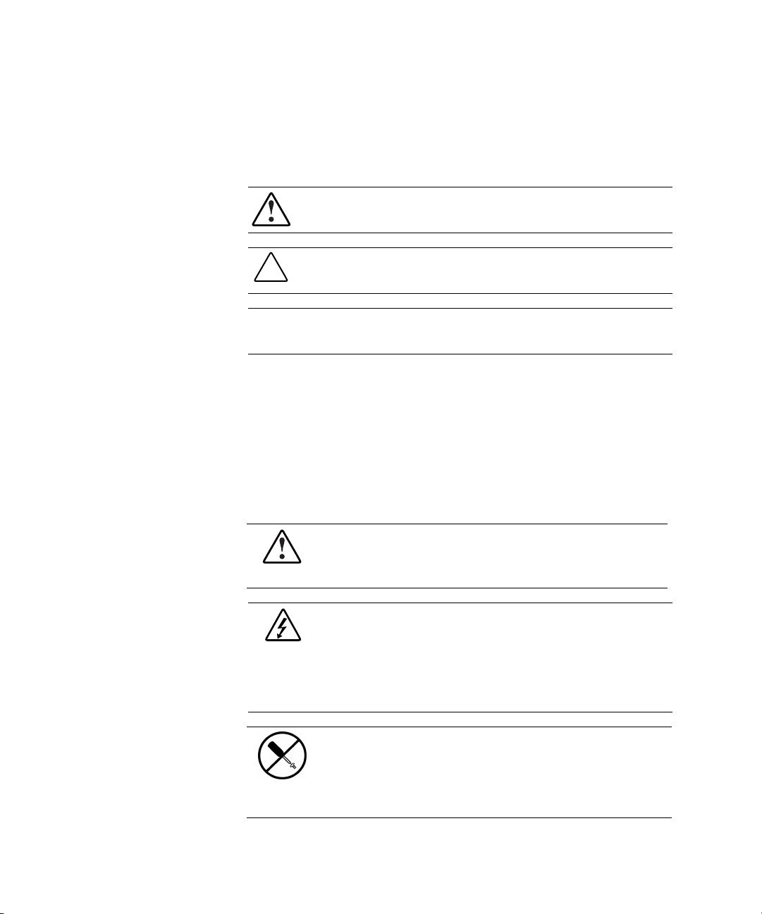
Figure 1-1. Front panel configuration
CMC Front Panel
Alarm LED
Network LED
Serial communication LED
Serial communication port (RJ-11)
Escape button
Scroll up button
Enter/Alarm silence button
LCD display
Power LED
Power button
8 9 10
75
Table 1-1
Page 16

1-6 Compaq Console Management Controller User Guide
Front Panel Controls
The CMC front panel includes the controls required to:
■ Power the unit On or Off.
■ Scroll through LCD menus.
■ Select LCD menu items.
■ Silence audible alarms and deactivate alarm relays (if these features are
enabled in the control software).
NOTE: For information about changing the configuration on the CMC, or to check the
current configuration, see Chapter 4, “Software.”
Front Panel LEDs
Each LED is described in the following table. See Table 1-1 for reference.
Table 1-2
Front Panel LEDs
LED Reference Color Meaning
NOTE: Alarm status may be viewed in the LCD display () or the system console.
Alarm LED Red General alarm indicator (blinking).
Orange Warning (intrusion alert/temperature warning).
Green No alarm.
Network LED Green Normally On. Blinking indicates activity.
Serial
Communication
LED
Power LED Green Power On.
Green Normally Off. Blinking indicates communication.
Page 17
Rear Panel
The CMC features the following rear panel configuration:
Overview 1-7
1 2 3 4 5 7 159 11 13
6 181614
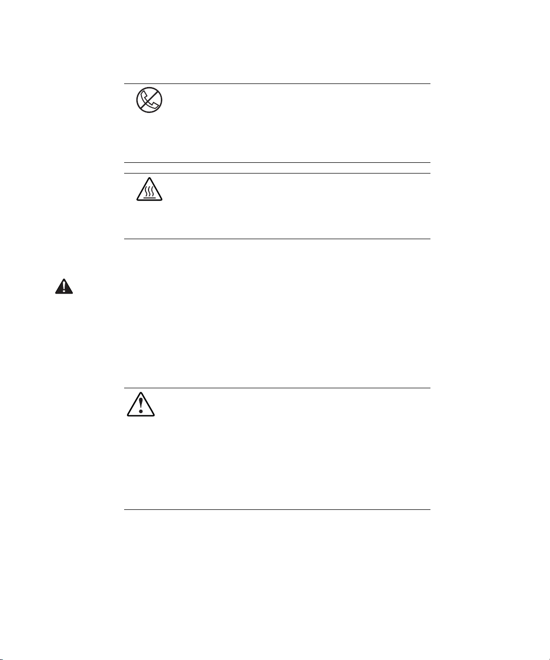
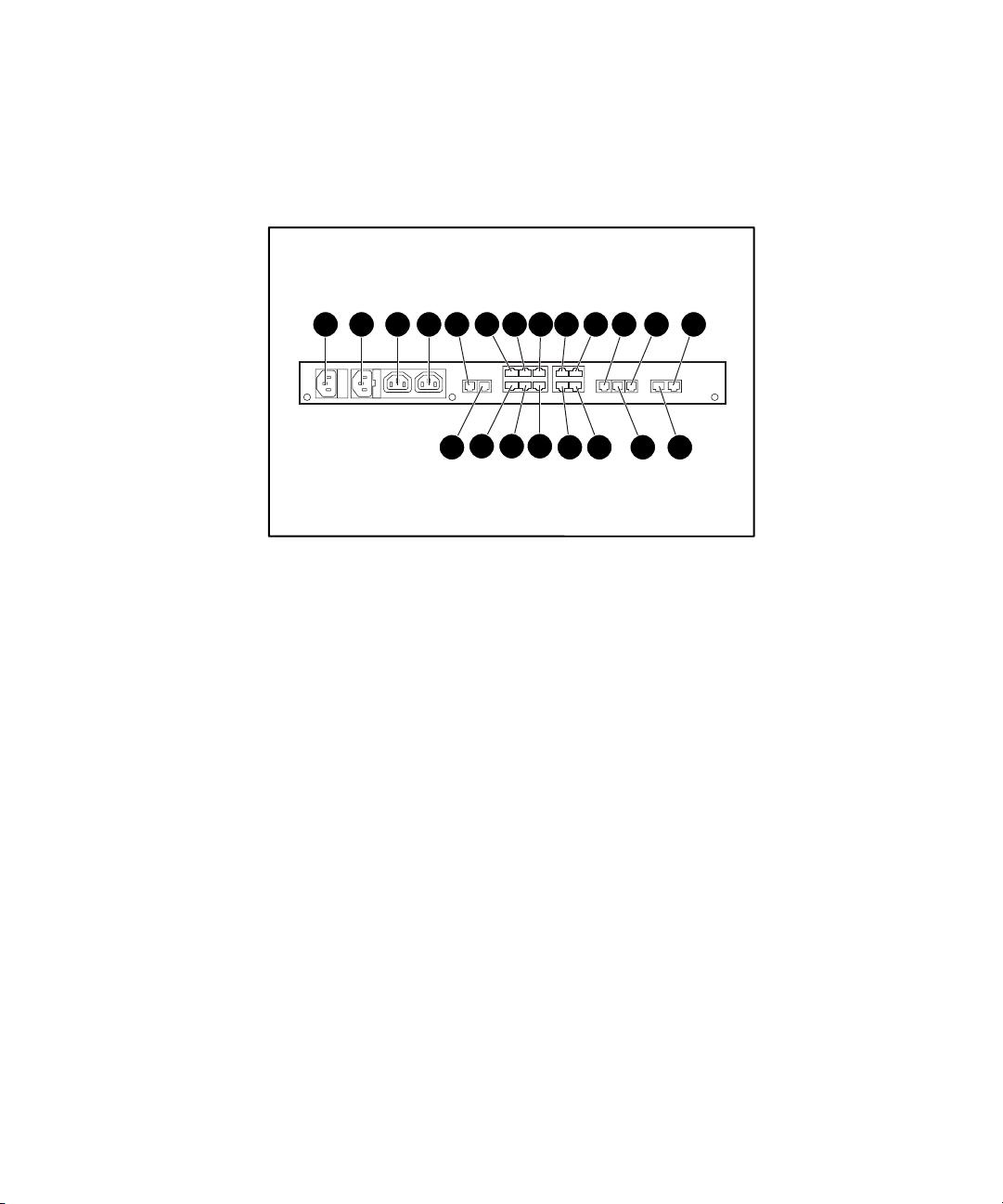
Figure 1-2. Rear panel configuration
211917
10 128
20
Page 18

1-8 Compaq Console Management Controller User Guide
Description Type of connector
Main power input AC input (IEC 320-10A)
Input voltage monitor / Power
input for Fan #1 and #2
Fan #1 Power output for fan #1 (IEC 320–10A)
Fan #2 Power output for fan #2 (IEC 320–10A)
Relay #1 Alarm relay (RJ-12)
Relay #2 Alarm relay (RJ-12)
Intrusion sensor #1 Discrete input (RJ-12)
Intrusion sensor #2 Discrete input (RJ-12)
Intrusion sensor #3 Discrete input (RJ-12)
Intrusion sensor #4 Discrete input (RJ-12)
Smoke sensor Discrete input (RJ-12)
Shock/vibration sensor Discrete input (RJ-12)
Lock #1 Discrete output (RJ-12)
Lock #2 Discrete output (RJ-12)
Auxiliary 1 Discrete input (RJ-12)
Auxiliary 2 Discrete input (RJ-12)
Temperature sensor #1 Analog input (RJ-12)
Temperature sensor #2 Analog input (RJ-12)
Humidity sensor Analog input (RJ-12)
2
C port I2C communications (RJ-45)
I
Ethernet port 10BaseT (RJ-45)
Table 1-3
CMC Rear Panel
AC input (IEC 320-10A)
Page 19

This chapter provides information on the following topics:
■ Installation requirements
■ Installation procedures
■ Powering on the CMC
■ Completing the installation
Chapter 2
Installation
Page 20
2-2 Compaq Console Management Controller User Guide
Installation Requirements
This section lists items required to install the CMC.
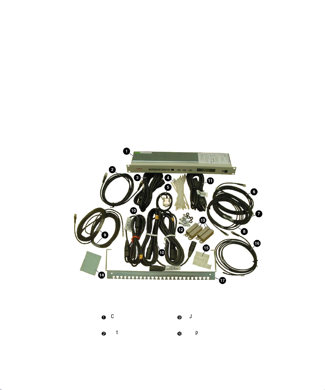
Items supplied with the basic CMC Kit
The CMC Kit (Compaq Part Number 203039-B21) contains the following
components:
Hardware
Figure 2-1. CMC kit contents (hardware)
Console Management
Controller
Network cable
(RJ-45 to RJ-45)
RJ-12 to pigtail cables for relay
ports
Jumper power cords for fan
arrays and for main input
power via UPS (IEC 320 to 320)
Page 21

Installation 2-3
Input power cord
(country-specific)
Tie wraps
Voltage monitor cord/fan input
cord (country-specific)
Screws, washers and cage
nuts
Serial communication cable
Intrusion sensors (2 sets)
(RJ-11 to DB-9)
Sensor cable
Sensor cable
Sensor cable
Double-sided tape
Cord management clips
Temperature sensor
Cord retention bracket
Software/Reference Material
■ Important Safety Information guide to be reviewed before installing this
product
■ Power Products Documentation CD
■ Compaq Intelligent Rack Manager Lite CD
■ Compaq Console Management Controller User Guide
■ Warranty information
Page 22
2-4 Compaq Console Management Controller User Guide
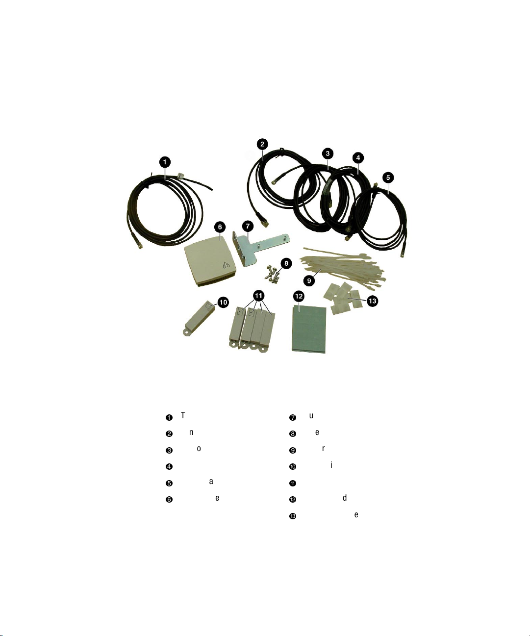
Optional Sensor Kit, with assorted cable lengths
Compaq Part Number 203039-B22
(sold separately)
Figure 2-2. Optional sensor kit content
Temperature sensor
Sensor cable
Sensor cable
Sensor cable
Sensor cable
Humidity sensor
Humidity sensor bracket
Screws and cage nuts
Tie wraps
Shock/vibration sensor
Intrusion sensors (2 sets)
Double sided tape
Cord management clips
Page 23
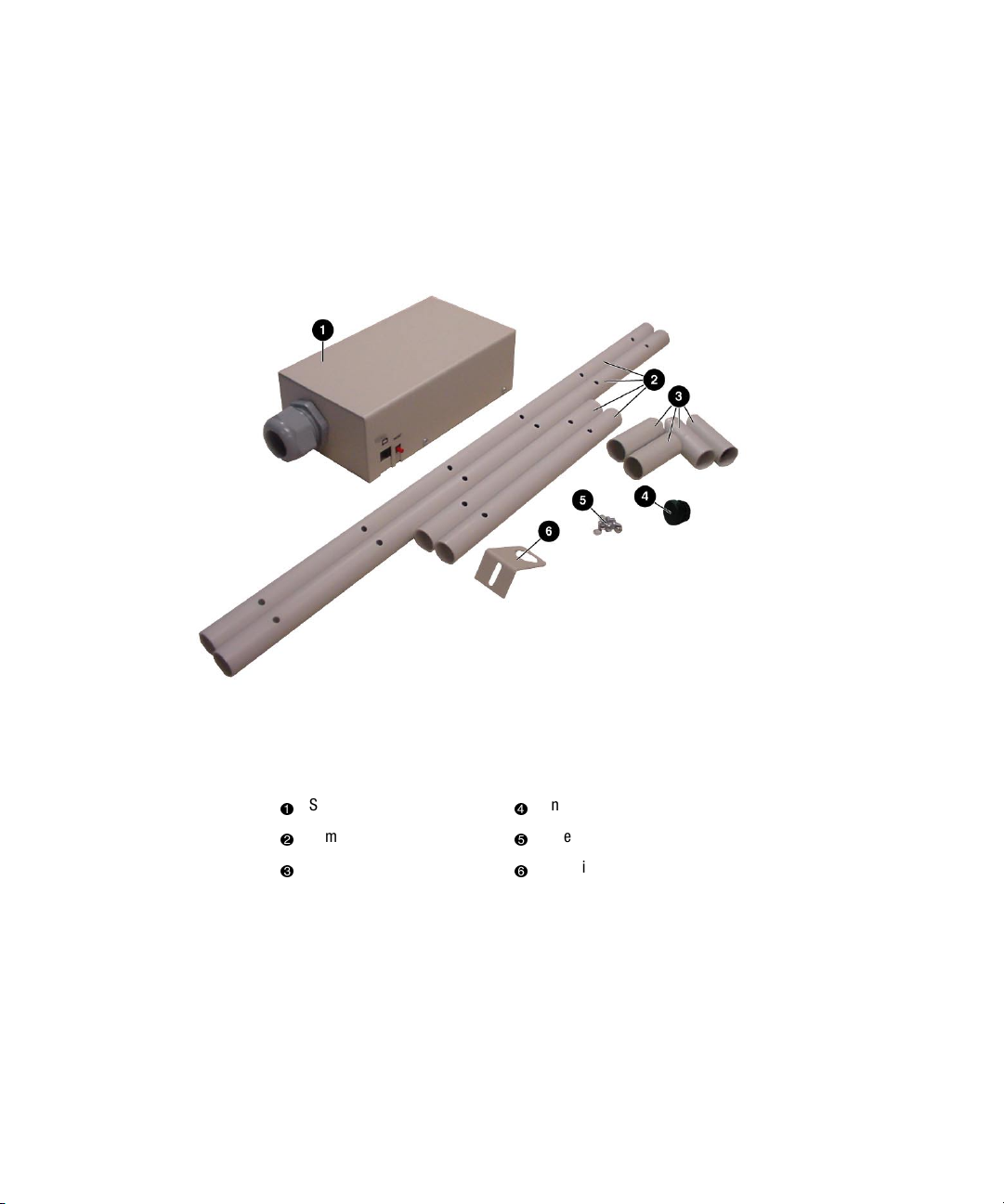
Optional Smoke Sensor Kit
Compaq Part Number 203039-B24
Installation 2-5
(sold separately)
Figure 2-3. Optional smoke sensor kit contents
Smoke sensor
Sampling tube sections
Tube couplings
End cap
Screws
Sampling tube bracket
Optional Door Locking Kit
Compaq Part Number 203039-B23
(sold separately)
Page 24

2-6 Compaq Console Management Controller User Guide
Items not supplied with the CMC Kit
Tools
■ A medium flat-bladed screwdriver and a #2 Phillips screwdriver
■ Cage nut-fitting tool (supplied with the Compaq rack)
IMPORTANT: Only use the power cords supplied with the CMC. If the CMC does not
include a power cord that is suitable for your application, contact an authorized Compaq
service representative to obtain the appropriate power cord. Refer to the “Precautions for
Power Products” section of Important Safety Information (guide included with the CMC
Kit.)
Page 25

Installation Procedures
This section provides installation steps to install the CMC.
1. Attach the cord retention bracket to the CMC.
2. Install the sensors in the racks.
3. Connect the sensors to the CMC unit.
4. Connect the main input power cord to the CMC, or if an Uninterruptible
Power System (UPS) will be used for main power, connect the power
jumper cord to the CMC.
5. Connect the input power/voltage monitor cord to the CMC.
6. Connect jumper power cords to the fan assemblies.
7. Secure the cables to the cord retention bracket.
8. Mount the CMC in the rack.
9. Plug the input power cord to a UPS or AC power source.
10. Plug the fan input power cord to an AC source.
11. Secure the cables to the rack.
Installation 2-7
12. Power up the CMC.
13. Set the initial configuration using the front panel controls.
14. Insert the software CD.
Page 26
2-8 Compaq Console Management Controller User Guide
Installing the Standard Sensors
The sensor cables may be routed through the rack and then attached to the rack
by using the stick-on cable management clips or tie wraps.
Temperature Sensor
The temperature sensor can be installed on the ceiling of the rack, towards the
rear, or near the most temperature-sensitive component in the rack.
Figure 2-4. Installing the temperature sensor
Page 27
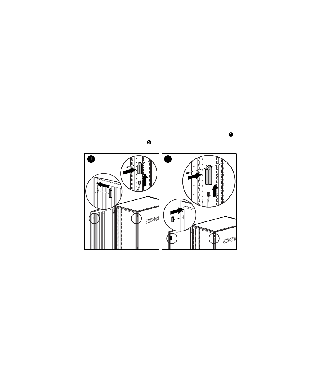
Intrusion Sensor
Intrusion Sensor
An intrusion sensor consists of two parts:
■ A magnet
■ An electrical switch
1. The magnet should be installed on the inside of the rack door and the
electrical switch on the rack as shown in the following instructions.
Make sure the magnet and switch align with each other and allow
sufficient clearance for the doors to close.
Installation 2-9
2. The intrusion sensors should be installed on the front door
as well as the rear door
1 2
Figure 2-5. Installing the intrusion sensor in the 9000 series rack
.
of the rack,
Page 28
2-10 Compaq Console Management Controller User Guide
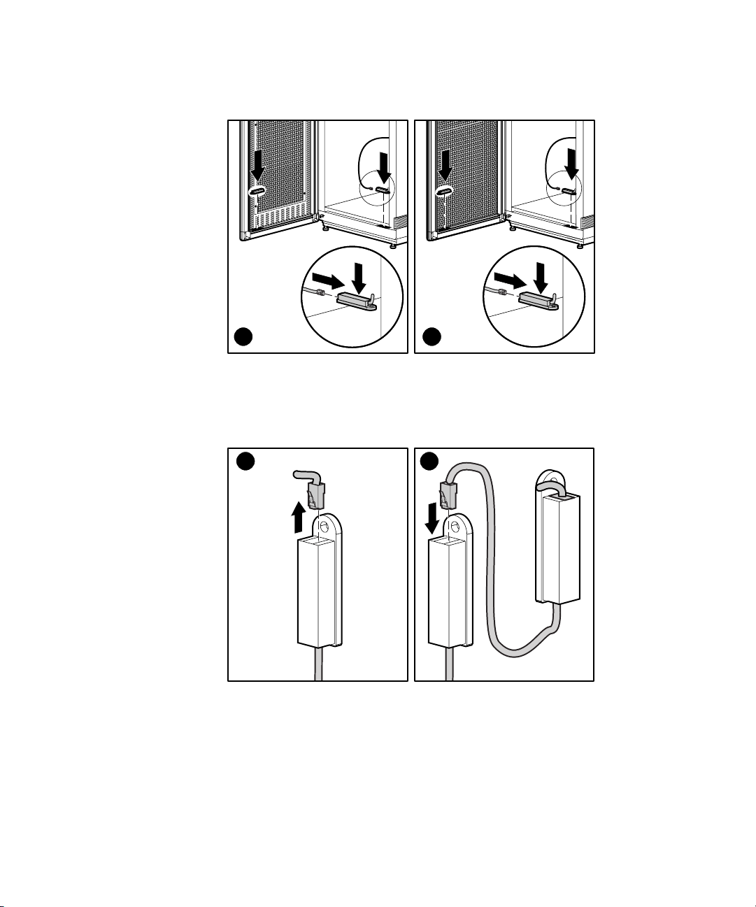
1 2
Figure 2-6. Installing the intrusion sensor in the 7000 series rack
To connect a series of intrusion sensors to the same CMC port, remove the
plug shipped in the sensor and connect the cable from an additional intrusion
sensor, as shown below.
21
Figure 2-7. Intrusion sensor
Page 29

Installing the Optional Sensors
Temperature sensor
■ The optional temperature sensor should be installed on the ceiling of the
second rack, towards the rear. (See Figure 2-4)
Intrusion sensor
■ The optional intrusion sensors should be mounted on the doors of the
second rack. (See Figures 2-5 and 2-6)
Installation 2-11
Page 30
2-12 Compaq Console Management Controller User Guide
Humidity sensor
■ The optional humidity sensor should be installed as follows:
a. Install the bracket for the humidity sensor
to the rack using the
larger screws.
b. Fasten the sensor unit
c. Snap the cover
d. Connect the sensor cable
2
3
Figure 2-8. Installing the humidity sensor in the 9000 series rack
to the bracket using the smaller screws.
over the sensor unit.
to the sensor unit.
4
1
2
3
Figure 2-9. Installing the humidity sensor in the 7000 series rack
4
1
Page 31

Installation 2-13
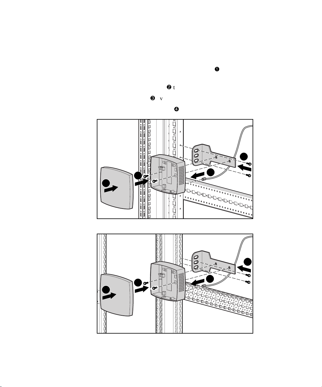
Mechanical shock/vibration sensor
■ Install the optional mechanical shock/vibration sensor on the rails of the
rack as follows:
Figure 2-10. Installing the vibration sensor in the 9000 rack
Figure 2-11. Installing the vibration sensor in the 7000 rack
Page 32

2-14 Compaq Console Management Controller User Guide
Smoke sensor kit
■ Install the optional smoke sensor as follows:
a. Place the smoke sensor
with washers
IMPORTANT: For the smoke sensor to be effective, the sampling tube must be placed in
the path of the exhaust air from the equipment within the rack.
through the holes in the door and secure the sensor.
on rear rack door. Then place the screws
b. Install a tube coupling on a section of the sampling tube. Insert the
coupling into the smoke sensor. Position the holes in the tube to face
the equipment in the rack. Hand-tighten the connection of the
coupling and smoke sensor.
c. Add couplings and tubes until the tube reaches the bottom of the
door.
d. Insert the plastic end cap on the bottom of the tube to secure the
bracket to the end of the tube
e. Align the bottom tube
f. Insert a screw
(with washer) through the hole in the door and
fasten it to the tube bracket
.
vertically with the sensor .
using a nut.
2
1
Figure 2-12. Installing the smoke sensor
4
3
Page 33

Installation 2-15
g. Route the sensor cable through the rack.
h. Attach the cable to the rack with the stick-on cable retention clips or
tie wraps included in the CMC basic unit.
i. Connect the cable to the sensor
Figure 2-13. Connecting the smoke sensor
.
1
Smoke Sensor Operation
NOTE: The smoke sensor is for use only with the CMC and is not suitable for connection
to building fire alarm systems.
Smoke passing by the sampling tube will be drawn into the optical smoke
sensor by the fan. The smoke sensor can take up to 20 seconds to trigger an
alarm to the CMC. The sampling tube must be placed in the path of the
exhaust air from the rack equipment.
If smoke is detected, the sensor fan will automatically shut off. After the
smoke has cleared, the sensor can be reset by pressing the RESET button for
three seconds.
The sensor will not detect smoke if the fan stops running or runs too slowly. A
fan fault like this will also trigger a smoke alarm. A smoke alarm should be
investigated to determine whether smoke is present or a fan fault occurred.
Page 34

2-16 Compaq Console Management Controller User Guide
Smoke Sensor Maintenance
Keep the sampling tube and holes clean and clear of dust and debris at all
times.
Check the smoke sensor at least once per year. Use smoke test gas to check
and verify proper unit functionality.
Compaq recommends replacing the smoke sensor after the sensor detects a
fire. Contact a Compaq authorized representative for ordering details.
Door locking kit
■ The optional door locking kit should be installed on the front and rear
doors of the rack. Install the optional door locking kit according to the
installation instructions included with the kit.
NOTE: The door locking kit is only for use with the Compaq CMC.
Page 35

Connecting the Cord Retention Bracket
Remove the screws from the rear of the CMC. Align cord retention bracket
with the holes in the rear of the unit and insert screws
Installation 2-17
.
1
1
Figure 2-14. Connecting the cord retention bracket
1
1
Page 36

2-18 Compaq Console Management Controller User Guide
Connecting the Sensors to the CMC
The sensors connect to the rear of the CMC. See Table 1-4, for a description of
the rear connectors.
1 2 3 4 5 7 159 11 13
6 181614
Figure 2-15. CMC rear panel
211917
10 128
20
Page 37

Connecting the Fan Assemblies
The fan assemblies should be connected to the fan power output sockets
and . The input power/voltage monitoring cord should be connected to
the input power plug
second rack.
2 3 4
. The cable A is connecting the rack fan array in the
A
Installation 2-19
Figure 2-16. Connecting fan assemblies
Page 38

2-20 Compaq Console Management Controller User Guide
Connecting the Input Power Cord to the CMC
Make sure the Power button is in the Off position before connecting the
input power cord to the rear of the unit.
Figure 2-17. Power Button
10
Connect the input power cord to the input power socket .
1
Figure 2-18. Input power connection
Page 39

Connecting the CMC to Utility Power
If a UPS is installed in the rack, connect the CMC to the UPS. If a UPS is not
installed in the rack, use a grounded utility power outlet.
The power for the fan outputs comes from the voltage monitor input. If the
rack configuration includes fans, the rack fans must be powered from the fan
power output sockets.
NOTE: Do not connect the voltage monitor input to a UPS.
WARNING: To reduce the risk of electric shock or damage to the equipment,
take these precautions:
■ Plug the input line cord into a grounded (earthed) electrical outlet that is
installed near the equipment and is easily accessible.
■ Do not disable the grounding plug on the input line cord. The grounding
plug is an important safety feature.
■ Do not use extension cords.
WARNING: Power grounds for the main AC input and the voltage monitor input
are tied common within the CMC.
Installation 2-21
Page 40

2-22 Compaq Console Management Controller User Guide
Connecting the Network Cable
Connect the network cable to the RJ-45 socket.
Figure 2-19. Connecting the network cable
Securing Cables to the CMC
Use the tie wraps (included with the CMC Kit) to secure the cables to the
cable retention bracket.
Figure 2-20. Securing cables to the CMC
Page 41

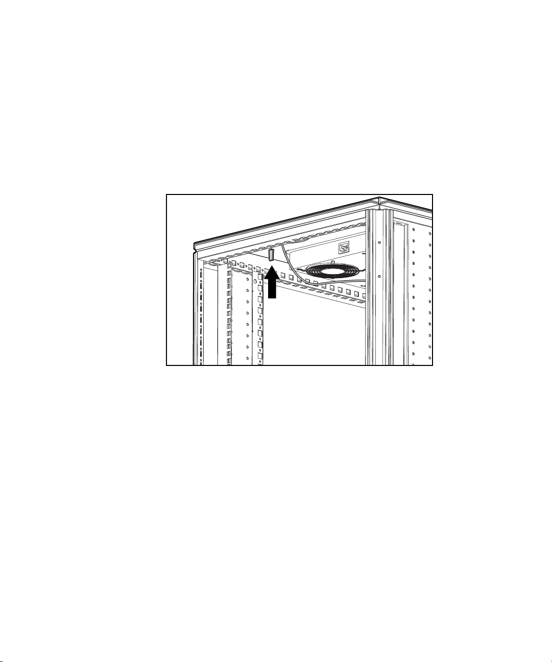
Mounting the CMC in the Rack
The CMC mounts directly to the rack in a 1U configuration. Refer to the
Compaq Console Management Controller Installation Instructions (supplied
with the CMC Kit) for directions.
Figure 2-21. Mounting the unit in the rack
Installation 2-23
Powering on the CMC
Power On the unit by pressing the Power button .
Figure 2-22. Turning the unit On
10
Page 42

2-24 Compaq Console Management Controller User Guide
Configuring the CMC
Use the front panel for basic configuration of the unit. The CMC is fully
localized to allow for complete functionality of the front panel in multiple
languages.
6
75
Figure 2-23. CMC front panel
8
Selecting the Language
Use the CMC front panel controls to select the appropriate language. To select
the language:
1. Press Scroll Up
2. Press Enter/Alarm Silence
to select the appropriate language.
to save the language selection.
Setting the IP Address
Use the CMC front panel controls to set the CMC IP address. To set the IP
address:
■ Press Scroll Up
and Enter/Alarm Silence to set the IP address.
Page 43

Setting the Subnet Mask
Installation 2-25
■ Press Scroll Up
address. The default setting is 0.0.0.0.
■ The CMC will automatically reboot.
NOTE: For more detailed configuration instructions, see Chapter 4, “Software.”
Using the Front Serial Port
The serial port on the front panel may be used with a laptop computer to
configure the CMC.
NOTE: For more detailed configuration instructions, see Chapter 4, “Software.”
and Enter/Alarm Silence to set the Subnet Mask
Figure 2-24. Connecting to the serial port
Installation Completion
Installation is now complete. For information on operating the CMC, see
Chapter 3, “Operation.” Use the Compaq website at www.compaq.com as an
additional information source.
Page 44

This chapter contains information on the following topics:
■ LCD menu
■ Alert handling
Chapter 3
Operation
Page 45

3-2 Compaq Console Management Controller User Guide
LCD Menu
6
75
Figure 3-1. LCD menu and control buttons
8
From the LCD menu , access information on Status, System Information,
and Setup.
Page 46

Status Menu
Operation 3-3
1. Press Enter/Alarm Silence
2. Press Enter/Alarm Silence
3. Press Scroll Up
G Temperature 1
G Temperature 2
G Fan 1
G Fan 2
G Voltage
G Humidity
G Door/Panel 1
G Door/Panel 2
G Door/Panel 3
G Door/Panel 4
G Lock Set 1
G Lock Set 2
G Locking dev. 1
to scroll through the menu selections:
one time to select the Main menu.
one time to select the Status menu.
G Locking dev. 2
G Smoke
G Mechanical shock/vibration
G Aux 1
G Aux 2
4. Press Escape
to return to the Main menu.
NOTE: If the external temperature sensors are not connected, the internal temperature of
the unit displays.
Page 47

3-4 Compaq Console Management Controller User Guide
System Information Menu
See Figure 3-1, for a description of the LCD menu.
1. Press Scroll Up
one time to access the System Information menu.
2. Press Enter/Alarm Silence
Information menu.
3. Press Scroll Up
G Hardware version
G Firmware version
G Software version
G Device number
G MIB version
G System name
G System location
G System contact
G Operating time
G System time
4. Press Escape
to scroll through the menu selections:
to return to the Main menu.
one time to select the System
Page 48

Setup Menu
Operation 3-5
See Figure 3-1, for a description of the LCD menu.
1. Press Scroll Up
2. Press Enter/Alarm Silence
3. Press Scroll Up
G Threshold fan 1
G Threshold fan 2
G Language
G Temperature unit
G IP address
G IP mask
G IP router
G Password - Enable/Disable
4. Press Escape
NOTE: To change one of these values, press Enter/Alarm Silence to select the entry,
Scroll Up to change the value, and Enter/Alarm Silence to confirm the change, or
Escape to cancel.
one time to access the Setup menu.
one time to select Setup menu.
to scroll through the menu selections:
to return to the System Information menu.
Page 49

3-6 Compaq Console Management Controller User Guide
Alert Handling
An alert triggers an action as configured in the software. Possible actions,
based on an alert, are identified below. Each alert can trigger any or all of
these actions.
■ Audible alarm
■ Activate relay #1
■ Activate relay #2
■ Send a Microsoft Windows message to monitoring computer
■ Send an alert via e-mail
■ Send an alert via pager
Examples:
■ Intrusion alert on Door #1 activates an audible alarm and pages the
system administrator.
■ Voltage out of specification pages the system administrator.
IMPORTANT: For more information regarding enabling and disabling alarms, see
Chapter 4, “Software.”
Page 50

Silencing an Audible Alarm
To silence an audible alarm, press Enter/Alarm Silence . You can enable or
disable the silencing feature in the software for all CMC alerts to ensure that
an unauthorized individual cannot turn off an audible alarm.
Figure 3-2. The Enter/Alarm Silence button
Operation 3-7
7
IMPORTANT
■ Pressing the Enter/Alarm Silence button quiets the alarm, but does not clear the
condition that originally initiated the alarm. The alert will remain active on the
management console until the condition returns to normal.
■ When the Enter/Alarm Silence button is pressed, silencing the alarm, any
subsequent alarm will again cause the alarm to sound.
Deactivating an Alarm Relay
To deactivate an alarm relay, press Enter/Alarm Silence . You can enable
or disable this deactivation feature in the software for all CMC alerts to ensure
that an unauthorized individual cannot turn off an active alarm relay output.
Page 51

This chapter describes the management of rack environments using Compaq
CMCs that are controlled using Compaq Intelligent Rack Manager Lite
software.
Compaq Intelligent Rack Manager Lite Software
Compaq Intelligent Rack Manager Lite software is a Java-based application
that runs a web server. Intelligent Rack Manager Lite ensures maximum
reliability of Compaq computer systems through flexible and comprehensive
remote monitoring of rack environments using Compaq CMCs. The software
compiles information about all network-connected CMCs, allowing remote
monitoring, configuration, management, and control of these devices.
Chapter 4
Software
NOTE: Compaq Intelligent Rack Manager Lite software is not essential for the operation
of the CMC. The basic configuration of the CMC can be operated with the following:
■ The front panel control buttons—Configuring a CMC with the front panel control
buttons is discussed in the section titled “LCD Menu,” in Chapter 3 of this guide.
■ A terminal program—Managing a CMC with a terminal program is discussed at the
end of this chapter.
Page 52

4-2 Compaq Console Management Controller User Guide
System Requirements
Intelligent Rack Manager Lite software requires the following minimum
hardware and software:
■ 100-MHz Pentium computer
G 50 MB free disk space
G 32 MB RAM
■ Windows NT 4.0 or Windows 2000
■ Internet Explorer 5.0 or later
■ A Mail Application Program Interface (MAPI)-compatible email system
for email notification of alerts
■ An installed modem for pager notification of alerts
Preinstallation Tasks
Use the CMC front panel controls to perform the following tasks before
beginning the software installation:
■ Selecting the language—See “Selecting the Language” in Chapter 2 of
this guide.
■ Setting the IP address—See “Setting the IP Address” in Chapter 2 of
this guide.
■ Setting the subnet mask—See “Setting the Subnet Mask” in Chapter 2
of this guide.
Page 53

Software Installation
The Intelligent Rack Manager Lite software CD is provided in the CMC kit.
NOTE: To install the Intelligent Rack Manager Lite software, you must have Administrator
rights.
To install the software using this CD:
1. Insert the CD into the CD-ROM drive of any network-connected
computer. If the AutoPlay feature is enabled, the Install Wizard
automatically starts. If the AutoPlay feature is disabled, explore the CD
and double-click INSTALL.HTM in the root directory to begin software
installation.
A security warning displays.
2. Click Yes to accept the security warning. The Intelligent Rack Manager
Lite CD menu displays.
3. Click Start Installer for Windows NT, 2000. The Install Wizard runs.
4. Select the appropriate language for the installation and click OK. The
Introduction window displays.
Software 4-3
5. Read the introduction and click Next. The License Agreement window
displays.
6. Read the license agreement, click Yes to accept the license agreement,
then click Next. The Choose Install Folder window displays.
7. Click Install to install the software in the default folder. To specify the
folder in which the software installs, click Choose..., navigate to the
appropriate folder, then click Install.
The software installation begins and a horizontal status bar indicates the
installation progress. The Install Complete window displays.
8. Click Done when the software is installed.
IMPORTANT: The Compaq Intelligent Rack Manager lite software application requires
Microsoft’s Virtual machine TM to be installed, in order to run properly. During the
software installation process you will be guided to the Microsoft Web page where
Microsoft Virtual Machine can be downloaded. Or, visit www.microsoft.com/java and
download the Virtual Machine prior to installing the Compaq Intelligent Rack Manager lite
software application.
NOTE: You will only be guided to the Microsoft web page if Virtual Machine is not already
installed.
Page 54

4-4 Compaq Console Management Controller User Guide
Uninstalling the Software
NOTE: To uninstall the Intelligent Rack Manager Lite software, you must have
Administrator rights.
To remove the Intelligent Rack Manager Lite software from the system:
1. Select Start, Programs.
2. Select the Compaq Intelligent Rack Manager Lite program group.
3. Select Uninstall. The software uninstalls.
Accessing the Software
Intelligent Rack Manager Lite can be accessed from the host computer or any
other network-connected computer.
To access the Intelligent Rack Manager Lite software from the host computer:
1. Select Start, Programs.
2. Select the Compaq Intelligent Rack Manager Lite program group.
3. Click Compaq Intelligent Rack Manager Lite. A browser window
opens and the Intelligent Rack Manager Lite software Login screen
displays.
To access the Intelligent Rack Manager Lite software from a
network-connected computer:
1. Double-click the Internet Explorer icon on the desktop or select Start,
Programs, Internet Explorer. The browser window displays.
2. In the Address field, type
http://location:8001/
where location is the IP address or the name of the computer on
which the software was installed. The computer name can only be used
if the computer has a DNS entry.
3. Click Go. The Intelligent Rack Manager Lite software Login screen
displays.
Page 55

Logging In to the Software
Figure 4-1. Login screen
Before using the Intelligent Rack Manager Lite software, you must log in with
a username and password. The first time you log in, enter
as the username and Administrator as the password. Click Enter
Password to log in. After you are logged in, customize your password as
described in “Change Password Screen” later in this chapter.
NOTE: Passwords are case sensitive.
Screen Layout
Software 4-5
Administrator
Figure 4-2. Intelligent Rack Manager Lite software screen layout
Page 56

4-6 Compaq Console Management Controller User Guide
The Intelligent Rack Manager Lite software interface is divided into three
frames:
■ Top frame—Contains the title, a Settings icon, a Devices icon, and a
Logout icon.
G Click the Settings icon to view a list of links to the software settings
screens.
G Click the Devices icon to view a list of links to the device
configuration screens.
G Click the Logout icon to log out of the software.
■ Left frame—Contains a list of links to other screens. The links in the
list change depending on which screen you are viewing.
■ Main frame—Contains the various screens of the software, which are
discussed in detail in the following sections. Click the Help icon on any
screen in the main frame to display the Compaq Intelligent Rack
Manager Lite software online help.
Software Settings
To configure the software, click the Settings icon in the top frame of the
interface. A list of links to software setup pages displays in the left frame:
■ Add/Remove Device
■ Messaging Setup
■ Email Setup
■ Pager Setup
■ Change Password
Each software settings screen is labeled Software Settings.
Page 57

Add/Remove Device Screen
Software 4-7
Figure 4-3. Add/Remove Device screen
Click the Add/Remove Device link to access the Add/Remove Device screen.
The Intelligent Rack Manager Lite software only recognizes CMC devices that
are listed on the Add/Remove Device screen.
To add a CMC to the software:
1. Type the IP address of the CMC in the IP Address field. See “Setting
the IP Address” in Chapter 2.
2. Click Add to add the CMC to the list of recognized devices.
NOTE: Type in a range of IP addresses to locate several CMC devices. The software only
recognizes ranges at the end of an IP address, for example 200.200.200.201-213.
To remove a CMC from the software:
1. Highlight the IP address of the CMC you want to remove.
2. Click Remove to remove the CMC from the list of recognized devices.
Page 58

4-8 Compaq Console Management Controller User Guide
Messaging Setup Screen
Figure 4-4. Messaging Setup screen
Click the Messaging Setup link to access the Messaging Setup screen. Use
this screen to set the computer names to which popup messages can be sent
when CMC alerts occur.
NOTE: The added computer names become available on the Alert Handling screen, where
each name must be configured to receive specific alerts. See the section “Alert Handling
Screen,” later in this chapter.
To add a computer name to the popup alert list:
1. Type a valid computer name in the Users field.
2. Click Add to add the name to the list.
To remove a computer name from the popup alert list:
1. Highlight the computer name you want to remove.
2. Click Remove to remove the name from the list.
Page 59

Email Setup Screen
Software 4-9
Figure 4-5. Email Setup screen
Click the Email Setup link to access the Email Setup screen. Use this screen
to set the email addresses to which email messages can be sent when CMC
alerts occur.
NOTE: The added email addresses become available on the Alert Handling screen, where
each address must be configured to receive specific alerts. See the section “Alert
Handling Screen,” later in this chapter.
Before email alerts can be sent, configure the software for the mail system:
NOTE: Ask the system administrator to assign a mail account to the Intelligent Rack
Manager Lite software.
1. Enter the hostname or IP address of a valid SMTP server, such as a
Microsoft Exchange server, in the SMTP Server field.
2. Enter a valid mailing address in the Username field. This address
displays in the From: field of all sent email messages.
3. Click Save to save the changes.
Page 60

4-10 Compaq Console Management Controller User Guide
To add an address to the email alert list:
1. Type a user’s valid email address in the Email Addresses field.
2. Click Add to add the address to the list.
To remove an address from the email alert list:
1. Highlight the email address you want to remove.
2. Click Remove to remove the address from the list.
Pager Setup Screen
Figure 4-6. Pager Setup screen
Click the Pager Setup link to access the Pager Setup screen. Use this screen
to set the phone numbers to which pager messages can be sent when CMC
alerts occur.
NOTE: The added phone numbers become available on the Alert Handling screen, where
each number must be configured to receive specific alerts. See the section “Alert
Handling Screen,” later in this chapter.
Page 61

Before pager alerts can be sent, configure the software to use the modem:
1. Enter the COM port to which the modem is connected in the
CommPort field.
2. Click Save to save the changes.
To add a phone number to the pager alert list:
1. Type a valid phone number for the pager and the Personal Identification
Number (PIN) in the Phone Numbers field. The format is
PHONE *PIN, where PHONE is the phone number for the pager and
PIN is the PIN number, for example, 18003451518 *1234.
2. Click Add to add the phone number to the list.
To remove a phone number from the pager alert list:
1. Highlight the phone number you want to remove.
2. Click Remove to remove the phone number from the list.
Change Password Screen
Software 4-11
Figure 4-7. Change Password screen
Click the Change Password link to access the Change Password screen. Use
this screen to change the password used to log in to the software.
NOTE: The software allows only one user. The user is called Administrator.
Page 62

4-12 Compaq Console Management Controller User Guide
To change the password:
1. Type the old password in the Old Password field. If changing the
password for the first time, the old password is Administrator.
2. Type the new password in the New Password field. Passwords must
contain at least eight characters.
NOTE: Passwords can contain 8 to 20 characters. Passwords are case sensitive.
3. Retype the new password in the Retype New Password field.
4. Click Save to save the changes or click Cancel to cancel the changes.
Device Configuration
To configure the individual CMC devices, click the Devices icon in the top
frame of the user interface. The IP addresses of all recognized CMCs display
in the left frame. Click the arrow next to each IP address for an expandable list
of available links for that CMC. The links to the device configuration pages
are as follows:
■ CMC Properties
■ Sensor Setup
■ Accessory Setup
■ Threshold Config
■ Alert Handling
■ Manual Control
■ Log
After a CMC is configured, each device configuration screen available for that
CMC is labeled with the CMC IP address, name, and physical location.
Page 63

CMC Properties Screen
Software 4-13
Figure 4-8. CMC Properties screen
Click the CMC Properties link to access the CMC Properties screen. Use
this screen to configure the CMC properties for each CMC recognized by the
Intelligent Rack Manager Lite software. The CMC hardware, software,
firmware, and MIB version levels are indicated in the Device Information
box. The availability of updated versions is indicated in the Status column.
Page 64

4-14 Compaq Console Management Controller User Guide
To configure a CMC:
1. Enter the name, physical location, and contact person for the CMC in
the Device Setup box.
2. Select the appropriate display language and temperature unit of measure.
3. Select the audible alarm Off radio button to permanently turn off the
audible alarm.
4. Enable the Press to Silence Alarm option to be able to silence
audible alarms from the front panel of the CMC.
5. Enter a password specific to this CMC and enable or disable the
password functionality. The CMC password can be up to six characters
in length. Characters can only be capital letters or numbers.
NOTE: If the password is enabled, the password is required to change the CMC
IP address and settings using the front panel controls or a terminal program.
6. Edit the SNMP Read/Write Community strings if necessary.
CAUTION: The SNMP Read/Write Community strings displayed on the CMC
Properties screen must match those on the CMC device. If you edit the strings
on this screen, be sure to make the same changes for the CMC device using a
terminal program as described in “Terminal Program Operation” in this chapter.
7. After entering the CMC properties, click Save to save the changes or
click Cancel to cancel the changes.
8. Click Return to view the Device Home screen for this CMC. The
Device Home screen is discussed in detail later in this chapter.
To update the MIB, software, and firmware for the CMC, click Update.
Page 65

Sensor Setup Screen
Software 4-15
Figure 4-9. Sensor Setup screen
Page 66

4-16 Compaq Console Management Controller User Guide
Click the Sensor Setup link to access the Sensor Setup screen. Use this
screen to configure the sensors.
To configure the sensors:
1. Select the Not Available radio button for each sensor that is listed as
available but not installed.
NOTE: For the initial system installation and boot, the CMC automatically recognizes
installed sensors and fans.
2. Set the appropriate fan and lock behavior when smoke is detected.
3. Set the sensitivity of the shock sensor, with 1 being low sensitivity and
10 being high sensitivity. The recommended setting is 5.
4. For Intrusion 1 through 4, enter the sensor description and set the fan
behavior and shock control when doors are opened.
IMPORTANT: For the door-locking feature to work properly, you must assign at least one
intrusion sensor to each lock set. For more information about the door-locking feature,
see “Accessory Setup Screen” in this chapter.
5. Enter the description and logic of sensors installed in Auxiliary 1 and 2.
6. After entering the sensor information, click Save to save the changes or
click Cancel to cancel the changes.
7. Click Return to view the Device Home screen for this CMC. The
Device Home screen is discussed in detail later in this chapter.
Page 67

Accessory Setup Screen
Software 4-17
Figure 4-10. Accessory Setup screen
Click the Accessory Setup link to access the Accessory Setup screen. Use
this screen to configure the CMC options.
Page 68

4-18 Compaq Console Management Controller User Guide
To configure the options:
1. Select whether each fan is installed (available) or not installed
(unavailable).
2. Select the appropriate logic for the alarm relays.
3. Enable the Press to Deactivate Relay option to be able to
deactivate relay output from the front of the CMC.
4. Select the appropriate options for each lock set.
a. Select whether each lock set is installed (available) or not installed
(unavailable).
b. Select the doors and panels that must be closed before the lock set
can activate the lock.
IMPORTANT: For the door-locking feature to work properly, you must assign at least one
intrusion sensor to each lock set. For more information about configuring intrusion
sensors, see “Sensor Setup Screen” in this chapter.
c. Set the lock sets to remain locked or to unlock in the event of each
listed fault. Enable the concealed door release to press a hidden
switch to manually unlock locked doors.
NOTE: The software cannot detect the concealed door release. Make sure the concealed
door release option is not selected for CMCs that control racks without a concealed door
release.
5. After entering the accessory information, click Save to save the changes
or click Cancel to cancel the changes.
6. Click Return to view the Device Home screen for this CMC. The
Device Home screen is discussed in detail later in this chapter.
Page 69

Threshold Configuration Screen
Software 4-19
Figure 4-11. Threshold Configuration screen
Click the Threshold Config link to access the Threshold Configuration
screen. Use this screen to modify the minimum and maximum acceptable
values for temperature, humidity, and voltage.
To modify the values:
1. Enter the minimum and maximum temperature, humidity, and voltage
values.
2. Enter the temperatures at which warnings are issued.
3. Enter the temperatures at which fans turn on and the degree of
temperature drop that must be achieved before fans turn off.
Page 70

4-20 Compaq Console Management Controller User Guide
4. After entering the threshold information, click Save to save the changes
or click Cancel to cancel the changes.
5. Click Return to view the Device Home screen for this CMC. The
Device Home screen is discussed in detail later in this chapter.
Alert Handling Screen
Figure 4-12. Alert Handling screen
Click the Alert Handling link to access the Alert Handling screen. Use this
screen to choose how the software will issue each type of alert for each CMC.
Alarms can be issued by message, pager, email, audible alarm, switch alarm
relay 1, or switch alarm relay 2.
To set the behavior for each type of alert:
1. Select an alert situation from the pull-down menu.
2. Select the appropriate type of alert for that situation.
3. Click Save to save the changes.
Page 71

4. Repeat steps 1 through 3 for each alert situation in the pull-down menu.
5. Click Return to view the Device Home screen for this CMC. The
Device Home screen is discussed in detail later in this chapter.
NOTE: Computer names, email addresses, and phone numbers that display on the Alert
Handling screen can be set using the software settings screens.
Manual Control Screen
Software 4-21
Figure 4-13. Manual Control screen
Click the Manual Control link to access the Manual Control screen. Use this
screen to manually control fan, door-locking, and alarm relay behaviors.
NOTE: Only enabled fans and enabled lock sets display on the Manual Control screen.
To enable fans and lock sets, see “Accessory Setup Screen” in this chapter.
Page 72

4-22 Compaq Console Management Controller User Guide
To manually control the behaviors:
1. Select the appropriate radio button to manually turn fans on or off.
2. Lock a door that is unlocked or unlock a door that is locked. Doors can
be unlocked after a specified amount of time has passed, immediately,
or manually by activating the concealed door release.
NOTE: Activating the concealed door release on the Manual Control screen allows the
door to be unlocked using a hidden switch one time. After the door is closed, the door
locking feature automatically locks the door and the concealed door release option is
disabled. To permanently enable the concealed door release, see “Accessory Setup
Screen” in this chapter.
3. Deactivate alarm relays as necessary. Alarm relays are only available
after they are activated by an alarm. The alarm relay logic is set up on
the Accessory screen.
4. Click Save to save the changes.
5. Click Return to view the Device Home screen for this CMC. The
Device Home screen is discussed in detail later in this chapter.
Page 73

Log Screen
Software 4-23
Figure 4-14. Log screen
Click the Log link to access the Log screen. Use this screen to view
information about alerts issued for the CMC.
■ Click Clear to clear all entries in the log.
■ Click Return to view the Device Home screen for this CMC.
■ Click Print on the browser window to print the log.
Device Monitoring
After the software and each recognized CMC are configured, monitor the
CMC device status with the following:
■ Active Alarms Screen
■ Device Home Screen
Page 74

4-24 Compaq Console Management Controller User Guide
Active Alarms Screen
Figure 4-15. Active Alarms screen
Click the Devices icon, then click the CMC Devices heading in the left frame
to access the Active Alarms screen. The Active Alarms screen automatically
displays each time you log in to the software. Use this screen to view a
summary of all active alarms and status information for all CMC devices. This
information automatically updates every 15 seconds, or you can update the
information at any time by clicking the Refresh link.
Click the IP address of a CMC in the list to display the Device Home screen
and view details for that device.
Table 4-1 lists the meanings of the status symbols used on the Active Alarms
screen.
Table 4-1
Active Alarms Status Symbols
Symbol Meaning
Normal
Minor
Major
Critical
Page 75

Device Home Screen
Figure 4-16. Device Home screen
The Device Home screen can be accessed by:
■ Clicking an IP address in the Active Alerts screen status list.
■ Clicking the IP address of a CMC in the left frame of the software
interface.
Software 4-25
■ Clicking Return at the bottom of any device configuration screen.
Use this screen to view status information about individual CMC devices. The
Device Home screen contains the following:
■ CMC IP address, designation, and physical location
■ A Refresh link
Page 76

4-26 Compaq Console Management Controller User Guide
Temperature, humidity, and voltage information in numerical and
■
graphical form, including an indication of whether the temperature is in
a safe range:
G White—Safe range
G Yellow—Warning
G Red—Critical
G Gray—No sensor
■ Component status information. Table 4-2 lists the meanings of the status
symbols used on the Device Home screen.
Device Home Status Symbols
Symbol Meaning
Table 4-2
Informational
Minor
Major
Critical
Page 77

Terminal Program Operation
Much of the Intelligent Rack Manager Lite software functionality is available
in a simpler, text-based interface using a host computer and a terminal
program over a serial connection to the CMC. See “Configuring the CMC” in
Chapter 2 of this guide for more information on connecting the CMC to a host
computer.
The serial link:
■ Provides some additional functionality that lets you configure the CMC
for operation with other SNMP managers. This feature is not needed for
Intelligent Rack Manager Lite-only systems.
IMPORTANT: Up to four Compaq Intelligent Rack Manager Lite consoles or other trap
monitors can be specified to receive alerts. The first trap receiver is always reserved for
the last Compaq Intelligent Rack Manager Lite management console that accessed the
CMC device. Compaq Intelligent Rack Manager Lite and other trap monitors, such as
Compaq Insight Manager XE, cannot be loaded on the same server.
■ Can be used to flash the memory with new CMC software. This
operation is normally performed using the Intelligent Rack Manager
Lite software over the network.
Software 4-27
Starting HyperTerminal
HyperTerminal is a terminal program that is included with Microsoft operating
systems. To start HyperTerminal:
1. Select Start, Programs.
2. Select Accessories and click HyperTerminal.
3. Do one of the following:
G For Windows NT 4.0, click HyperTerminal.
G For Windows 2000, click Communications, then click
HyperTerminal.
Page 78

4-28 Compaq Console Management Controller User Guide
4. Set up the properties for your terminal connection:
a. Enter a name for your connection in the New Connection dialog
box. Select an icon to represent the connection, then click OK. The
Phone Number dialog box displays.
b. In the Connect Using field, select Direct Connection to the COM
port to which the CMC is connected, then click OK. The Properties
dialog box displays.
c. Enter the following port settings, then click OK.
Bits per second (baud rate) 9600
Data bits 8
Parity None
Stop bits 1
Flow control None
5. The main menu of the CMC displays on the HyperTerminal interface.
Navigating Menus
CAUTION: All configuration changes made in a terminal program are retained in
CMC memory. If you change the Read and Write Community strings in the
terminal program setup independently from the Compaq Intelligent Rack
Manager Lite software, the software can no longer control the CMC.
Use Table 4-3 as a reference when navigating the CMC menus.
■ To change values in HyperTerminal, type the new value in the field and
press Enter.
■ To select and toggle values, press the spacebar.
■ To save changes and jump back to the previous menu, press Esc.
Page 79

Software 4-29
Table 4-3
CMC Terminal Program Menus
Main Menu Items Submenu 1 Items Submenu 2 Items Brief Description
Values Display rack information.
Status Display rack status.
Network
configuration
IP configuration
IP Address
IP Subnetmask
IP Router
Trap receiver
configuration
IP Trap receiver
Enable/Disable
IP Trap receiver
Enable/Disable
IP Trap receiver
Enable/Disable
IP Trap receiver
Enable/Disable
Set network addresses.
Set up to 4 trap receiver IP
addresses. Trap receiver
number 1 is dedicated to
the Compaq Intelligent
Rack Manager software.
Any IP address entered in
number 1 will be over
written when used with the
software.
SNMP IP Access
SNMP Manager
SNMP Manager
SNMP Manager
SNMP Manager
SNMP Manager
SNMP Manager
SNMP Manager
SNMP Manager
SNMP Manager
SNMP Manager
SNMP Manager
SNMP Manager
Set the authorized IP
addresses of the
management computers.
In the default setting (all
addresses set to 0.0.0.0),
all network IP addresses
are SNMP-authorized. If
one or more IP addresses
are entered, only those IP
addresses have SNMP
authorization. SNMP
communication with the
CMC can only be
established from this
system.
continued
Page 80

4-30 Compaq Console Management Controller User Guide
Table 4-3
CMC Terminal Program Menus
Main Menu Items Submenu 1 Items Submenu 2 Items Brief Description
continued
Network
configuration
(continued)
General setup
Setup Detectors
(Analog/Fans)
Enable TFTP
Enable Auth. Traps
Read Community
Write Community
System Name
System Contact
System Location
Change Password
Enable Password
Activate actual values
Language
Temperature unit
Audible Alarm
Quit Alarm relay 1
Quit Alarm relay 2
Logic Alarm relay 1
Logic Alarm relay 2
Set date of internal clock
Set time of internal clock
Temperature 1 available
Temperature 2 available
Fan1 available
Fan2 available
Voltage available
Humidity available
Set network properties. All
configuration changes are
retained in CMC memory.
Changing the Read or
Write Community strings
independent of the
software prevents the
software from being able
to control the CMC. If
Enable TFTP is disabled,
the Compaq Intelligent
Rack Manager software
will not be able to perform
firmware upgrades.
Configure general CMC
properties.
Set up sensors.
continued
Page 81

Table 4-3
CMC Terminal Program Menus
Main Menu Items Submenu 1 Items Submenu 2 Items Brief Description
continued
Software 4-31
Setup Detectors
(Digital)
Set up sensors.
Input 1
Available
Description
Fan option
Shock option
Input 2
Available
Description
Fan option
Shock option
Input 3
Available
Description
Fan option
Shock option
Input 4
Available
Description
Fan option
Shock option
Smoke sensor
Available
Fan option
Shock sensor
Available
Sensibility
continued
Page 82

4-32 Compaq Console Management Controller User Guide
Table 4-3
CMC Terminal Program Menus
Main Menu Items Submenu 1 Items Submenu 2 Items Brief Description
continued
Setup Detectors
(Digital)
(continued)
Thresholds Sets threshold values.
Aux 1
Available
Description
Logic
Aux 2
Available
Description
Logic
Warning temp.1
Max.temp.1
Min.temp.1
Warning temp.2
Max.temp.2
Min.temp.2
Fan 1
Setpoint Fan 1
Hysteresis Fan 1
Fan 2
Setpoint Fan 2
Hysteresis Fan 2
Temperature unit
Max.voltage
Min.voltage
Max.humidity
Min.humidity
continued
Page 83

Software 4-33
Table 4-3
CMC Terminal Program Menus
Main Menu Items Submenu 1 Items Submenu 2 Items Brief Description
Alert handling Configure alert handling.
Temperature 1
Temperature 2
Fan 1
Fan 2
Voltage
Humidity
continued
Alarm relays max
Alarm relays warning
Alarm relays min
Audible Alarm max
Audible Alarm warning
Audible Alarm min
Alarm relays max
Alarm relays warning
Alarm relays min
Audible Alarm max
Audible Alarm warning
Audible Alarm min
Alarm relays
Audible Alarm
Alarm relays
Audible Alarm
Alarm relays max
Alarm relays min
Audible Alarm max
Audible Alarm min
Alarm relays max
Alarm relays min
Audible Alarm max
Audible Alarm min
continued
Page 84

4-34 Compaq Console Management Controller User Guide
Table 4-3
CMC Terminal Program Menus
Main Menu Items Submenu 1 Items Submenu 2 Items Brief Description
continued
Alert handling
(continued)
System Info
Defaults
Aux 1
Aux 2
Set thresholds to default
Set setup to default
Alarm relays
Audible Alarm
Alarm relays
Audible Alarm
Display system data and
network addresses.
Revert settings to default
values.
Page 85

Troubleshooting
This chapter provides information on the following topics:
■ Troubleshooting during startup
■ Troubleshooting after startup
■ Repairing the CMC
Chapter 5
Page 86

5-2 Compaq Console Management Controller User Guide
Troubleshooting During Startup
If problems occur when starting the Compaq CMC, select the appropriate
symptom for possible causes and actions.
Troubleshooting Guide (CMC Startup)
Description of Fault Symptom Solution
power up.
Table 5-1
Check the AC power connection.The CMC fails to function after
Make sure unit is On.
Connected sensors are not
recognized by the CMC.
Alarm signals are only indicated on
the CMC but not at the console
management.
There is no shock alarm, despite
the presence of vibrations.
Intrusion alarms do not activate
when door is opened.
sensors are connected.
any signals.
Make sure sensor is connected to correct port on
the rear of the CMC.
Check the cables to the sensors for cable breaks.
If applicable, check the power supply to the
sensors.
Verify network connection is correctly installed.
Verify the correct IP address is programmed into
the unit.
Contact network administrator.
Use software to adjust sensitivity. See Chapter 4.
Verify intrusion magnetic switches are properly
installed.
Verify sensors connected to the correct port on the
rear of the unit.
Check the sensors for correct installation.Faults are not reported although
Verify that sensors are connected to the proper
port on the rear of the unit.
Check the connection to the network.The interface LEDs are not giving
Contact network administrator.
Page 87

Troubleshooting After Startup
For problems that occur after the CMC started, these suggested actions address
possible causes.
Troubleshooting Guide (After Startup)
Symptom Possible Cause Suggested Action
Audible Alarm Alarm condition exists. Check display or console for
Repairing the CMC
Repairs to the CMC must be carried out by Compaq or a Compaq authorized
service representative. The only user-serviceable parts are the fuses located in
the rear of the unit. If the fuses have opened, verify that the condition that
caused the fault has been cleared. Replace the fuse with the exact rating as
specified on the unit label. Contact your Compaq authorized service
representative for more details.
Troubleshoo ting 5-3
Table 5-2
error condition and clear.
WARNING: Disconnect all power cords before servicing the unit.
Page 88

Regulatory Compliance Notices
Regulatory Compliance Identification Numbers
For the purpose of regulatory compliance certifications and identification, the
Compaq CMC model is assigned a Compaq Series Number. The Compaq
Series Number for this product is shown in the following table. The CMC
Series Number can be found on the Regulatory Compliance label, along with
the required approval markings and information. The Regulatory Compliance
label is located on the top of the CMC unit. When requesting certification
information for this product always refer to this series number. This series
number should not be confused with the marketing name or model number for
your Compaq CMC.
Appendix A
Table A-1
Compaq CMC Series Number
Series Number CMC Model
EO3009 Worldwide model - 100 to 240V
Page 89

A-2 Compaq Console Management Controller User Guide
Federal Communications Commission Notice
Part 15 of the Federal Communications Commission (FCC) Rules and
Regulations has established Radio Frequency (RF) emission limits to provide
an interference-free radio frequency spectrum. Many electronic devices,
including computers, generate RF energy incidental to their intended function
and are, therefore, covered by these rules. These rules place computers and
related peripheral devices into two classes, A and B, depending upon their
intended installation. Class A devices are those that may reasonably be
expected to be installed in a business or commercial environment. Class B
devices are those that may reasonably be expected to be installed in a
residential environment (that is, personal computers). The FCC requires
devices in both classes to bear a label indicating the interference potential of
the device as well as additional operating instructions for the user.
The rating label on the device shows which class (A or B) the equipment falls
into. Class B devices have an FCC logo or FCC ID on the label. Class A
devices do not have an FCC logo or FCC ID on the label. Once the class of the
device is determined, refer to the following corresponding statement.
Class A Equipment
This equipment has been tested and found to comply with the limits for a
Class A digital device, pursuant to Part 15 of the FCC Rules. These limits are
designed to provide reasonable protection against harmful interference when
the equipment is operated in a commercial environment. This equipment
generates, uses, and can radiate radio frequency energy and, if not installed
and used in accordance with the instructions, may cause harmful interference
to radio communications. Operation of this equipment in a residential area is
likely to cause harmful interference, in which case the user will be required to
correct the interference at personal expense.
Page 90

Class B Equipment
This equipment has been tested and found to comply with the limits for a
Class B digital device, pursuant to Part 15 of the FCC Rules. These limits are
designed to provide reasonable protection against harmful interference in a
residential installation. This equipment generates, uses, and can radiate radio
frequency energy and, if not installed and used in accordance with the
instructions, may cause harmful interference to radio communications.
However, there is no guarantee that interference will not occur in a particular
installation. If this equipment does cause harmful interference to radio or
television reception, which can be determined by turning the equipment off
and on, the user is encouraged to try to correct the interference by one or more
of the following measures:
■ Reorient or relocate the receiving antenna.
■ Increase the separation between the equipment and receiver.
■ Connect the equipment into an outlet on a circuit different from that to
which the receiver is connected.
■ Consult dealer or experienced radio or television technician for help.
Declaration of Conformity for Products Marked
with the FCC logo - United States Only
This device complies with Part 15 of the FCC Rules. Operation is subject to
the following two conditions: (1) this device may not cause harmful
interference, and (2) this device must accept any interference received,
including interference that may cause undesired operation.
■ For questions regarding your product, contact:
Compaq Computer Corporation
P. O. Box 692000, Mail Stop 530113
Houston, Texas 77269-2000
or call 1-800-652-6672 (1-800-OK COMPAQ)
■ For questions regarding this FCC declaration, contact:
Compaq Computer Corporation
P. O. Box 692000, Mail Stop 510101
Houston, Texas 77269-2000
or call (281) 514-3333.
Regulatory Compliance Notices A-3
1
.
To identify this product, refer to the Part, Series, or Model number found on
the product.
1
For continuous quality improvement, calls may be recorded or monitored.
Page 91

A-4 Compaq Console Management Controller User Guide
Modifications
The FCC requires the user to be notified that any changes or modifications
made to this device that are not expressly approved by Compaq Computer
Corporation may void the user's authority to operate the equipment.
Canadian Notice (Avis Canadien)
Class A Equipment
This Class A digital apparatus meets all requirements of the Canadian
Interference-Causing Equipment Regulations.
Cet appareil numérique de la classe A respecte toutes les exigences du
Règlement sur le matériel brouilleur du Canada.
Class B Equipment
This Class B digital apparatus meets all requirements of the Canadian
Interference-Causing Equipment Regulations.
Cet appareil numérique de la classe B respecte toutes les exigences du
Règlement sur le matériel brouilleur du Canada.
Page 92

European Union Notice
Products with the CE Marking comply with both the EMC Directive
(89/336/EEC) and the Low Voltage Directive (73/23/EEC) issued by the
Commission of the European Community.
Compliance with these directives implies conformity to the following
European Norms (in brackets are the equivalent international standards):
■ EN50091-1 – CMC Product Safety Requirements
■ EN50091-2 – CMC EMC Requirements
Japanese Notice
July 14 version
Regulatory Compliance Notices A-5
China Taiwan Notice
Page 93

Appendix B
Electrostatic Discharge
To prevent damaging the system, be aware of the precautions you need to
follow when setting up the system or handling parts. A discharge of static
electricity from a finger or other conductor may damage system boards or
other static-sensitive devices. This type of damage may reduce the life
expectancy of the device.
To prevent electrostatic damage, observe the following precautions:
■ Avoid hand contact by transporting and storing products in static-safe
containers.
■ Keep electrostatic-sensitive parts in their containers until they arrive at
static-free workstations.
■ Place parts on a grounded surface before removing them from their
containers.
■ Avoid touching pins, leads, or circuitry.
■ Make sure you are always properly grounded when touching a
static-sensitive component or assembly.
Page 94

B-2 Compaq Console Management Controller User Guide
Grounding Methods
There are several methods for grounding. Use one or more of the following
methods when handling or installing electrostatic-sensitive parts:
■ Use a wrist strap connected by a ground cord to a grounded workstation
or computer chassis. Wrist straps are flexible straps with a minimum of
1 megohm
proper ground, wear the strap snug against the skin.
■ Use heel straps, toe straps, or boot straps at standing workstations. Wear
the straps on both feet when standing on conductive floors or dissipating
floor mats.
■ Use conductive field service tools.
■ Use a portable field service kit with a folding static-dissipating work
mat.
If you do not have any of the suggested equipment for proper grounding, have
a Compaq authorized reseller install the part.
NOTE: For more information on static electricity, or assistance with product installation,
contact your Compaq authorized reseller.
±10 percent resistance in the ground cords. To provide
Page 95

Appendix C
Specifications
This appendix provides specifications that apply to the Compaq CMC:
■ Physical specifications
■ Environmental specifications
■ Input/Output specifications
Page 96

C-2 Compaq Console Management Controller User Guide
Specifications
Specifications – Console Management Controller (CMC)
Feature Specification
Dimensions Height 1.75 in (1U) 44.5 mm
Depth 4.13 in 105 mm
Width 19 in 483 mm
Table C-1
U.S. Metric
Operating
temperature
Storage
temperature
Processor AM186 based (20 MHz), 16-bit CPU, Intel-compatible
RAM 512KB 16-bit DRAM
Program memory 512KB flash-EPROM
CMC Rated
voltage
CMC Maximum
input current
rating
Voltage drop time 10 ms (maximum)
Rated voltage for
fan inlet/outlets
rating for fans
+10°C to +50°C
-20°C to +60°C
100 VAC to 240 VAC, 50/60 Hz
300mA
100 VAC to 240 VAC, 50/60 Hz
Fan inlet - 4AMaximum current
Fan outlet - 2A (each)
continued
Page 97

Table C-1
Specifications – Console Management Controller (CMC)
Feature Specification
Serial interface RS-232
Ethernet connection 10BaseT, IEEE 802.3 (10 MB/sec), TCP/IP, SNMP, TFTP
continued
Specifications C-3
Fuses
Alarm relays 1 and 2 Contacts: S.P.D.T., 800 mA @ 24VDC
Maximum DC output
(Alarm relay ports)
Displays 4 LEDs, LCD display (2 lines x 20 characters)
Audible Alarm Piezoelectric signal generator
Main AC input power-250V, 800mA, T, IEC-127
Fan #1 switched power-250V, 2A, T, IEC-127
Fan #2 switched power-250V, 2A, T, IEC-127
160 mA @ 24VDC (See Appendix D)
Page 98

Compaq CMC
The RJ-12 connector pins on the rear of the CMC are identified in the following figure. The
RJ-12 pin functions are described in Table D-1.
Appendix D
Pin Layout Configuration
1
6
Figure D-1. RJ-12 ports
Page 99

D-2 Compaq Console Management Controller
Alarm Relay Wiring Examples
Figure D-2. Alarm relay wiring examples
Page 100

Table D-1
RJ-12 Pin Layout Specifications
Pin Layout Configuration D-3
Pin Temperature
sensor
1 Sensor Humidity signal (4mA to
2 Sensor Ground (4mA to 20mA) Contact of
3- - - - Contact NO
Humidity sensor Discrete
inputs
Contact of
20mA)
sensor
sensor
Smoke sensor Alarm relays
Contact of sensor Contact NC
3
Contact of sensor Contact C
3
1
1
1
4- - - - -
5 - Ground - Ground Ground
6 - 24VDC, 44mA 24VDC, 160 mA 24VDC, 160mA
2
Note: 1. The alarm relay contacts are rated for a maximum of 24VDC and 800mA, when connecting to an external
power source.
2. The CMC can supply up to 160mA to users from its internal 24VDC power supply via the two alarm relay
ports. The 160mA can be split as needed between the two ports.
3. Intrusion sensors can be connected to Auxiliary 1 and 2 input ports to allow monitoring additional doors.
Users may also wire a simple switch closure device between pins 1 and 2. Pin 2 is connected to the CMC
signal ground and pin 1 is connected to the CMC signal input. Opening or closing the switch will trigger an
alarm, as configured in the software setup.
 Loading...