

Page 1

HP 1910 Fast Ethernet Switch Series
Getting Started Guide
Part number: 5998-3955
Document version: 5W100-20130620
Page 2

Legal and notice information
© Copyright 2013 Hewlett-Packard Development Company, L.P.
No part of this documentation may be reproduced or transmitted in any form or by any means without
prior written consent of Hewlett-Packard Development Company, L.P.
The information contained herein is subject to change without notice.
HEWLETT-PACKARD COMPANY MAKES NO WARRANTY OF ANY KIND WITH REGARD TO THIS
MATERIAL, INCLUDING, BUT NOT LIMITED TO, THE IMPLIED WARRANTIES OF MERCHANTABILITY
AND FITNESS FOR A PARTICULAR PURPOSE. Hewlett-Packard shall not be liable for errors contained
herein or for incidental or consequential damages in connection with the furnishing, performance, or use
of this material.
The only warranties for HP products and services are set forth in the express warranty statements
accompanying such products and services. Nothing herein should be construed as constituting an
additional warranty. HP shall not be liable for technical or editorial errors or omissions contained herein.
i
Page 3

Contents
Product overview ·························································································································································· 1
1910-8 panel views ·························································································································································· 1
1910-24 panel views ······················································································································································· 2
1910-48 panel views ······················································································································································· 2
1910-8-PoE+ panel views ················································································································································ 3
1910-24-PoE+ panel views ·············································································································································· 3
Preparing for installation ············································································································································· 1
Safety recommendations ·················································································································································· 1
Examining the installation site ········································································································································· 1
Temperature/humidity ············································································································································· 1
Cleanness ·································································································································································· 2
EMI ············································································································································································· 2
Installing the switch ······················································································································································ 1
Mounting the switch in a 19-inch rack with mounting brackets ··················································································· 1
Mounting the switch on a workbench ····························································································································· 3
Connecting cables ···························································································································································· 4
Connecting network cable ······································································································································ 4
Installing SFP transceiver module and connecting optical fiber ·········································································· 4
Connecting the console cable ································································································································· 5
Connecting the AC power cord ······························································································································ 6
Verifying the installation ··················································································································································· 7
Accessing the switch for the first time ························································································································· 1
Setting up the configuration environment ······················································································································· 1
Connecting the console cable ········································································································································· 1
Console cable ··························································································································································· 1
Connection procedure ············································································································································· 2
Setting terminal parameters ············································································································································· 2
Powering on the switch····················································································································································· 5
Verification before power-on ·································································································································· 5
Powering on the switch ············································································································································ 5
Appendix A Troubleshooting ······································································································································ 6
Appendix B Technical specifications ·························································································································· 1
Appendix C LED description ······································································································································· 1
Power LED ································································································································································· 1
Ethernet copper port LEDs ······································································································································· 1
SFP transceiver module link LED ····························································································································· 1
SFP transceiver module active LED ························································································································· 2
PoE LED ······································································································································································ 2
i
Page 4
Regulatory Model Name
HNGZA-HA0001
HNGZA-HA0002
HNGZA-HA0003
HNGZA-HA0004
HNGZA-HA0005
Product overview
The HP 1910 Switch Series includes the models in Table 1.
Table 1 HP 1910 Switch Series models
Product code HP description Alias
Non-PoE
JG536A HP 1910-8 Switch 1910-8
JG538A HP 1910-24 Switch 1910-24
JG540A HP 1910-48 Switch 1910-48
PoE
JG537A HP 1910-8-PoE+ Switch 1910-8-PoE+
JG539A HP 1910-24-PoE+ Switch 1910-24-PoE+
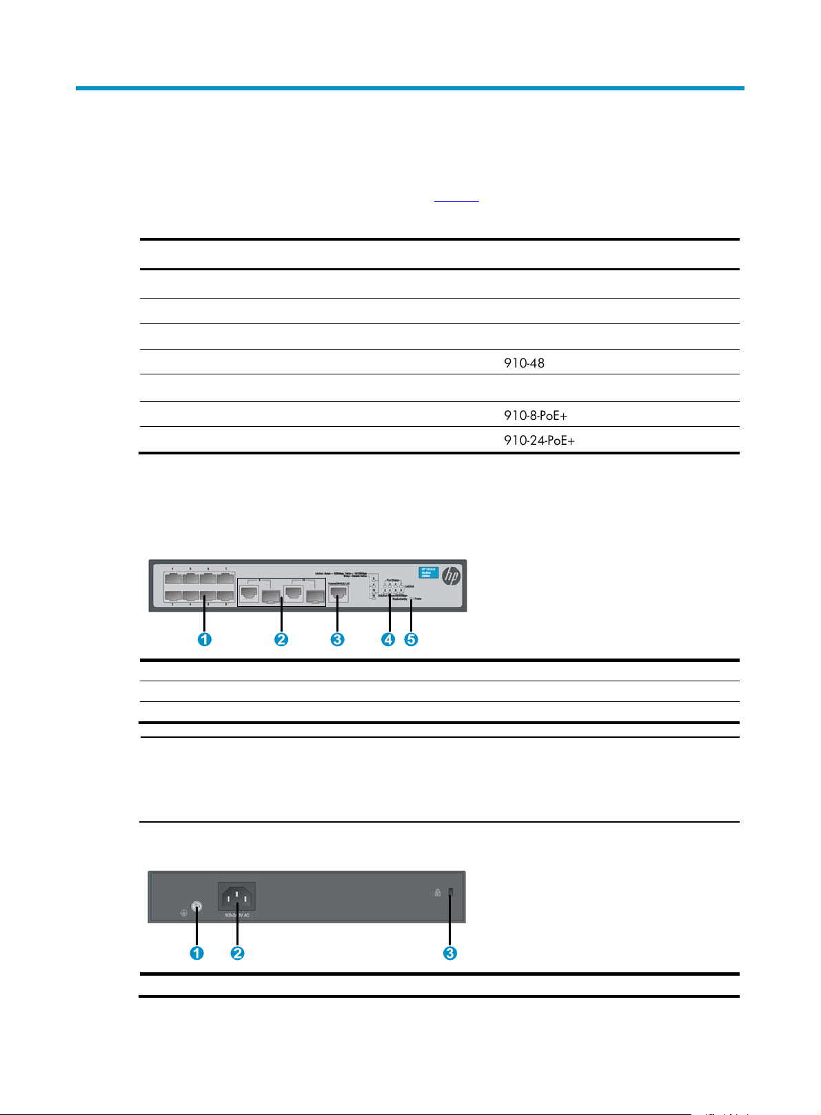
1910-8 panel views
Figure 1 Front panel
(1) 10/100Base-T auto-sensing Ethernet port
(3) Console port (4) Port LED
(5) Power LED (Power)
NOTE:
The 10/100Base-T Ethernet ports of the HP 1910 switch are numbered from the upper left to the lower
right. From left to right, the ports in the upper line are numbered odd numbers 1, 3, 5, and so on, and
those in the lower line are numbered even numbers 2, 4, 6, and so on.
Figure 2 Rear panel
(2) Combo interface
(1) Grounding screw (2) AC-input power receptacle (3) Anti-theft hole
1
Page 5
A
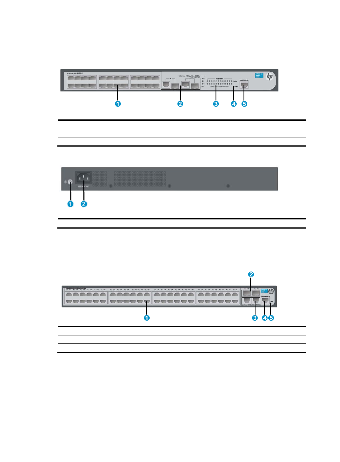
1910-24 panel views
Figure 3 Front panel
(1) 10/100Base-T auto-sensing Ethernet port
(3) Port LED (4) Power LED (Power)
(5) Console port
Figure 4 Rear panel
(1) Grounding screw (2)
1910-48 panel views
Figure 5 Front panel
(2) Combo interface
C-input power receptacle
(1) 10/100Base-T auto-sensing Ethernet port
(3) 100/1000Base-T auto-sensing Ethernet port
(5) Power LED (Power)
(2) 1000Base-X SFP port
(4) Console port
2
Page 6
A
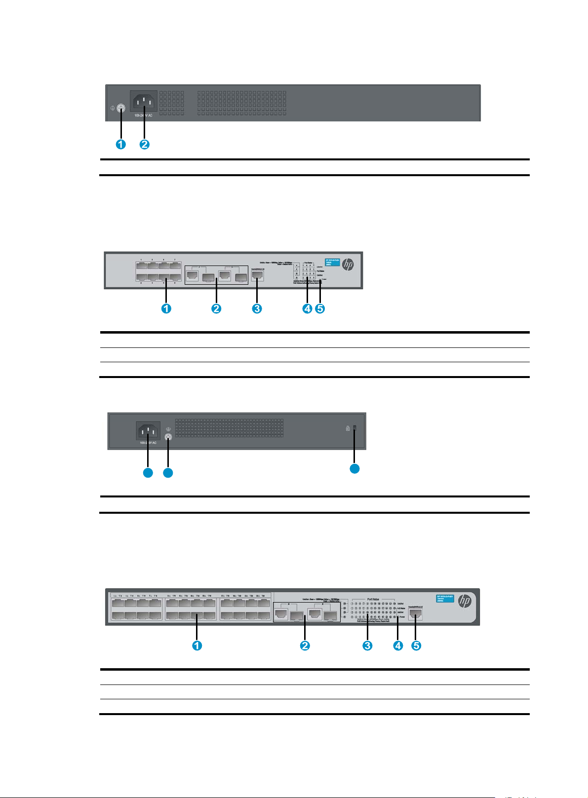
Figure 6 Rear panel
(1) Grounding screw (2) AC-input power receptacle
1910-8-PoE+ panel views
Figure 7 Front panel
(1) 10/100Base-T auto-sensing Ethernet port
(3) Console port (4) Port LED
(5) Power LED (Power)
Figure 8 Rear panel
21
(1) AC-input power receptacle (2) Grounding screw
1910-24-PoE+ panel views
Figure 9 Front panel
(2) Combo interface
3
(3)
nti-theft hole
(1) 10/100Base-T auto-sensing Ethernet port
(3) Port LED (4) Power LED (Power)
(5) Console port
(2) Combo interface
3
Page 7

A
Figure 10 Rear panel
(1) Grounding screw (2)
C-input power receptacle
4
Page 8

Preparing for installation
Safety recommendations
To avoid any equipment damage or bodily injury caused by improper use, read the following safety
recommendations before installation. The recommendations do not cover every possible hazardous
condition.
• Do not store the switch without power too long due to the storage requirement for the electrolytic
capacitor in the switch.
• Take proper anti-interference measures because the switch might cause radio interference as a
class-A product.
• Before cleaning the switch, remove all power cords from the switch. Do not clean the switch with wet
cloth or liquid.
• Do not place the switch near water or in a damp environment. Prevent water or moisture from
entering the switch chassis.
• Do not place the switch on an unstable case or desk. The switch might be severely damaged in case
of a fall.
• Ensure proper ventilation of the equipment room and keep the air inlet and outlet vents of the switch
free of obstruction.
• Make sure that the operating voltage is in the required range.
• To avoid electrical shocks, do not open the chassis while the switch is operating or when the switch
is just powered off.
• The accessories shipped with the switch, including but not limited to power cables, are intended
only for the switch. Please do not use them for other products.
Examining the installation site
The HP 1910 switches must be used indoors. You can mount your switch in a rack or on a workbench, but
make sure:
• Adequate clearance is reserved (at least 5 cm or 1.97 in) at the air inlet and exhaust vents for
ventilation.
• The rack or workbench has a good ventilation system.
• The rack or workbench is sturdy enough to support the switch and its accessories.
• The rack or workbench is well earthed.
To ensure normal operation and long service life of your switch, install it in an environment that meets the
requirements described in the following subsections.
Temperature/humidity
Maintain appropriate temperature and humidity in the equipment room.
• Lasting high relative humidity can cause poor insulation, electricity creepage, mechanical property
change of materials, and metal corrosion.
1
Page 9

• Lasting low relative humidity can cause washer contraction and ESD and bring problems including
loose captive screws and circuit failure.
• High temperature can accelerate the aging of insulation materials and significantly lower the
reliability and lifespan of the switch.
For the temperature and humidity requirements of different switch models, see "Appendix B Technical
specifications.
Cleanness
Dust buildup on the chassis may result in electrostatic adsorption, which causes poor contact of metal
components and contact points, especially when indoor relative humidity is low. In the worst case,
electrostatic adsorption can cause communication failure.
Table 2 Dust concentration limit in the equipment room
Substance Concentration limit (particles/m³)
EMI
Dust
NOTE:
Dust diameter ≥ 5 μm
≤ 3 x 10⁴ (no visible dust on the tabletop over three days)
The equipment room must also meet strict limits on salts, acids, and sulfides to eliminate corrosion and
premature aging of components, as shown in Table 3
.
Table 3 Harmful gas limits in the equipment room
Gas Maximum concentration (mg/m
SO
2
H2S 0.006
NH3 0.05
Cl2 0.01
0.2
3
)
All electromagnetic interference (EMI) sources, from outside or inside of the switch and application
system, adversely affect the switch in a conduction pattern of capacitance coupling, inductance coupling,
electromagnetic wave radiation, or common impedance (including the grounding system) coupling. To
prevent EMI, take the following actions:
• If AC power is used, use a single-phase three-wire power receptacle with protection earth (PE) to
filter interference from the power grid.
• Keep the switch far away from radio transmitting stations, radar stations, and high-frequency
devices.
• Use electromagnetic shielding, for example, shielded interface cables, when necessary.
• Route interface cables only indoors to prevent signal ports from getting damaged by overvoltage or
overcurrent caused by lightning strikes.
2
Page 10

W
g
Installing the switch
The HP 1910 switch can be installed in a 19-inch rack or on a workbench.
ARNING!
Before installing or moving the switch, remove the power cord.
Mounting the switch in a 19-inch rack with mounting brackets
To install the switch with mounting brackets:
1. Wear an ESD-preventive wrist strap and make sure it makes good skin contact and is well
grounded.
2. Ensure the rack is securely grounded and stands stably.
3. Fix the mounting brackets on the sides of the front panel with screws.
NOTE:
The mounting brackets are used only for fixing the switch instead of bearing the switch wei
on the rack is used to bear the switch weight.
Figure 11 Installing the mounting brackets to the HP 1910-8 switch
Figure 12 Installing the mounting brackets to the HP 1910-8-PoE+ switch
ht. A holder
1
Page 11

Figure 13 Installing the mounting brackets to the HP 1910-24-PoE+/1910-24/1910-48 switch
4. Place the switch on a holder in the rack, and push the switch in along the guide rails until the oval
holes in the brackets aligns with the mounting holes in the rack posts.
5. Fix the mounting brackets to the rack posts with screws.
Figure 14 Mounting the HP 1910-8 switch in the rack
2
Page 12

Figure 15 Mounting the HP 1910-8-PoE+ switch in the rack
Figure 16 Mounting the HP 1910-24-PoE+/1910-24/1910-48 switch in the rack
Mounting the switch on a workbench
3
Page 13

IMPORTANT:
• Ensure good ventilation and 10 cm (3.9 in) of clearance around the chassis for heat dissipation.
• Avoid placing heavy objects on the switch.
To mount the switch on a workbench:
1. Check that the workbench is sturdy and well grounded.
2. Place the switch with bottom up, and clean the round holes in the chassis bottom with dry cloth.
3. Attach the rubber feet to the four round holes in the chassis bottom.
4. Place the switch with upside up on the workbench.
Figure 17 Attaching rubber feet (1910-24-PoE+)
Connecting cables
Connecting network cable
Use crossover cable or straight through cable to connect a PC or other network devices to the Ethernet
port of the switch.
Figure 18 Connecting network cable
Installing SFP transceiver module and connecting optical fiber
4
Page 14

W
NOTE:
CAUTION:
• Hold the SFP transceiver module by its two sides when you install or remove the module. Do not touch
the golden finger of the module.
• Remove the optical fiber, if any, from a transceiver module before installing it.
To install an SFP transceiver module and connect the optical fiber:
1. Wear an ESD-preventive wrist strap and make sure it makes good skin contact and is well
grounded.
2. Pivot the clasp of the module up. Holding the module, gently push the module into the slot until it
has firm contact with the slot (when the top and bottom spring tabs catch in the slot).
3. Remove the protection covers from the optical fiber and the transceiver module, and connect the LC
connector of the optical fiber to the transceiver module.
Keep the protection covers for future use.
Figure 19 Installing SFP transceiver module and connecting optical fiber
Connecting the console cable
ARNING!
Do not connect or remove the console cable to or from the PC if the switch has been powered on.
To connect a terminal, for example, a PC, to the switch:
1. Wear an ESD-preventive wrist strap and make sure it makes good skin contact and is well
grounded.
2. Plug the DB-9 female connector of the console cable to the serial port of the PC.
3. Connect the RJ-45 connector to the console port of the switch.
Figure 20 Connecting the console cable
5
Page 15

NOTE:
To disconnect the console cable, plug out the RJ-45 connector of the cable and then the DB-9 female
connector.
Connecting the AC power cord
To connect the AC power cord:
1. Wear an ESD-preventive wrist strap and make sure it makes good skin contact and is well
grounded.
2. Make sure the correct power source is used.
3. Connect one end of the AC power cord to the AC-input power receptacle on the switch.
Figure 21
4. Connect the other end of the AC power cord to the AC power outlet.
5. Check the Power LED. If it is ON, it means the power connection is correct.
Figure 21 Connecting the AC power cord
shows the power cord connection on the switch.
6
Page 16

Verifying the installation
After you complete the installation, verify that:
• There is enough space for heat dissipation around the switch, and the rack or workbench is stable.
• The grounding cable is securely connected.
• The correct power source is used.
• The power cords are properly connected.
• All the interface cables are cabled indoors. If any cable is routed outdoors, verify that the socket
strip with lightning protection and lightning arresters for network ports have been properly
connected.
7
Page 17
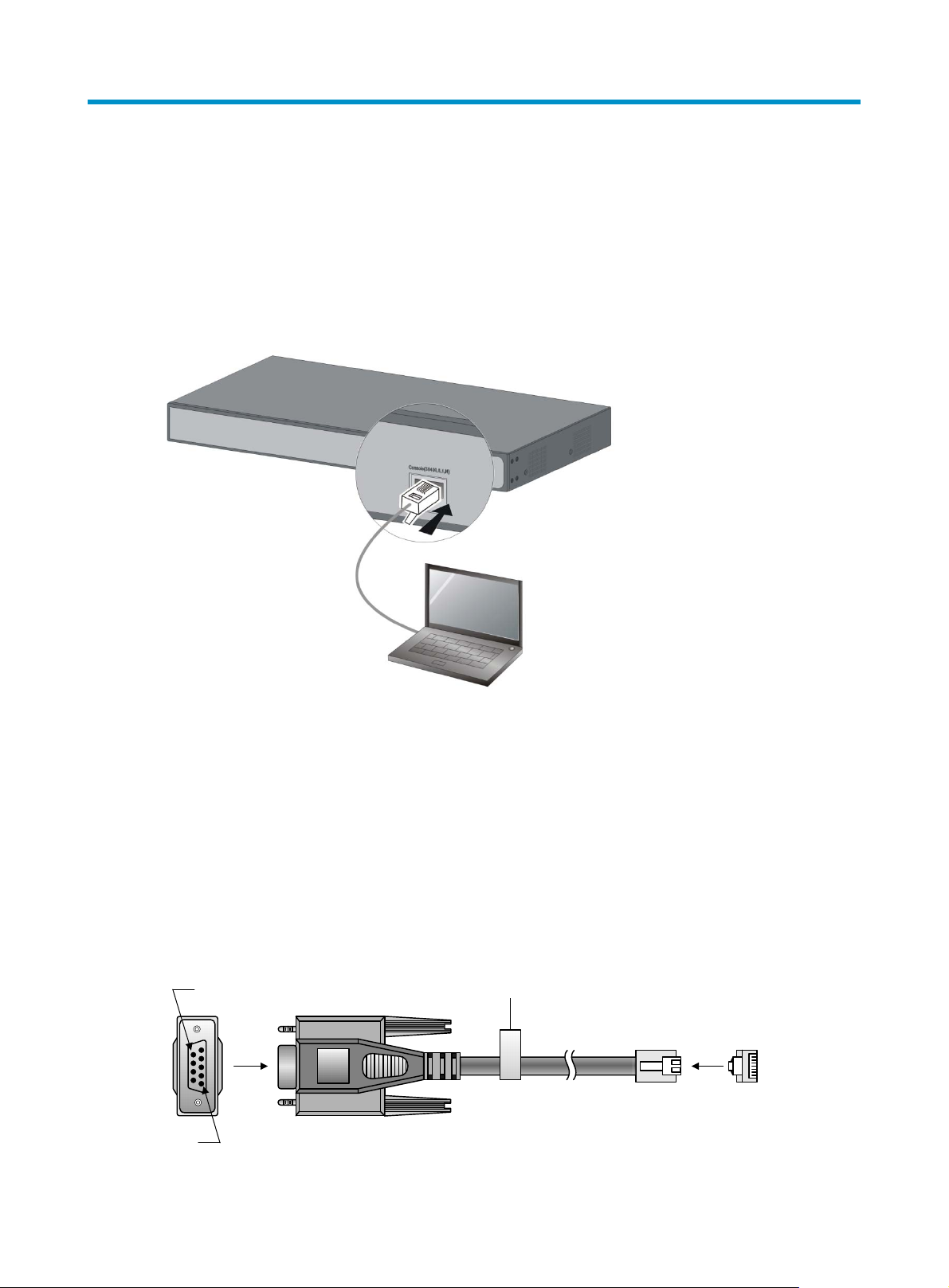
Accessing the switch for the first time
Setting up the configuration environment
The first time you access the switch you must use a console cable to connect a console terminal, for
example, a PC, to the console port on the switch.
Figure 22 Connect the console port to a terminal
Connecting the console cable
Console cable
A console cable is an 8-core shielded cable, with a crimped RJ-45 connector at one end for connecting
to the console port of the switch, and a DB-9 female connector at the other end for connecting to the
serial port on the console terminal.
Figure 23 Console cable
A side
Pos.9
A
Pos.1
Main label
8
1
B side
B
1
Page 18

Connection procedure
To connect a terminal, for example, a PC, to the switch:
1. Plug the DB-9 female connector of the console cable to the serial port of the PC.
2. Connect the RJ-45 connector to the console port of the switch.
NOTE:
• Identify the mark on the console port and make sure that you are connecting to the correct port.
• The serial ports on PCs do not support hot swapping. If the switch has been powered on, connect the
console cable to the PC before connecting to the switch, and when you disconnect the cable, first
disconnect from the switch.
Setting terminal parameters
To configure and manage the switch, you must run a terminal emulator program on the console terminal.
The following are the required terminal settings:
• Bits per second—38,400
• Data bits—8
• Parity—None
• Stop bits—1
• Flow control—None
• Emulation—VT100
To set terminal parameters, for example, on a Windows XP HyperTerminal:
1. Select Start > All Programs > Accessories > Communications > HyperTerminal.
The Connection Description dialog box appears.
2. Enter the name of the new connection in the Name field and click OK.
Figure 24 Connection description
2
Page 19

Select the serial port to be used from the Connect using list, and click OK.
3.
Figure 25 Set the serial port used by the HyperTerminal connection
4. Set Bits per second to 38400, Data bits to 8, Parity to None, Stop bits to 1, and Flow control to
None, and click OK.
Figure 26 Set the serial port parameters
5. Select File > Properties in the HyperTerminal window.
3
Page 20

Figure 27 HyperTerminal window
6. On the Settings tab, set the emulation to VT100 and click OK.
Figure 28 Set terminal emulation in Switch Properties dialog box
4
Page 21

Powering on the switch
Verification before power-on
Before powering on the switch, verify that:
• The power cord is properly connected.
• The input power voltage meets the requirement of the switch.
• The console cable is properly connected, the terminal or PC used for configuration has started, and
the configuration parameters have been correctly set.
Powering on the switch
Power on the switch, for example, an 1910-24-PoE+ switch, and you can see the following information:
Starting......
****************************************************************************
* *
* HP 1910-24-PoE+ Switch JG5389 BootWare, Version 1.02 *
* *
****************************************************************************
Copyright (c) 2010-2013 Hewlett-Packard Development Company, L.P.
Compiled Date : Mar 20 2013 17:00:53
CPU Type : MIPS4kec
CPU L1 Cache : 16KB
CPU Clock Speed : 500MHz
Memory Type : DDR3 SDRAM
Memory Size : 128MB
Memory Speed : 300MHz
BootWare Size : 3MB
Flash Size : 32MB
BootWare Validating...
Press Ctrl+B to enter extended boot menu...
Starting to get the main application file--flash:/hp1910_24_poe.bin!........
..............
The main application file is self-decompressing.............................
............................................................................
............................................................................
............................................................................
............................................................................
............................................................................
............................................................................
............................................................................
............................................................................
............................................................................
5
Page 22

............................................................................
............................................................................
............................................................................
............................................................................
............................................................................
............................................................................
............................................................................
............................................................................
............................................................................
........................................................Done!
System application is starting...
User interface aux0 is available.
Press ENTER to get started.
Press Enter and the system displays the following prompt:
<Hp>
This prompt indicates that the switch is ready to configure.
Appendix A Troubleshooting
This chapter lists some issues that you may encounter while using and managing the switch, with
corrective action to take.
If you encounter an issue that is not listed here and you cannot solve it, please contact your local
technical support representative.
Table 4 Troubleshooting
Symptom Troubleshooting method
1. Verify that the correct power source is used and the power cords are
Power LED off
LAN interface LED off
properly connected.
2. Verify that the power source side provides power supply normally.
1. Verify that the network cable is properly connected to the network
port of the switch.
2. Plug the two ends of a network cable into two network ports of the
switch. If the port LEDs are on, it indicates that the network cable is
well. Otherwise, please replace the network cable.
6
Page 23

Symptom Troubleshooting method
1. Use the ping command to check the network connectivity:
a. Ping 127.0.0.1 to verify that TCP/IP has been installed.
b. Ping the management IP address of the switch to verify that the
management PC is connected to the switch. If not, perform the
following check:
{ For local configuration, verify that the IP addresses of the
management PC and the switch are in the same subnet.
Unable to log on to the Web
interface of the HP 1910 switch
{ For remote configuration, verify that the route from the
management PC to the switch is reachable.
2. Check the LED status to verify that the cables are connected
properly.
3. Verify that the switch's port that connects to the management PC is
enabled and belongs to the management VLAN.
4. Verify that the Web browser is not configured with proxy or dial-up
connection.
5. Disable and then enable the local network after you complete local
network settings.
7
Page 24

Appendix B Technical specifications
Table 5 Technical specifications
Item 1910-8 1910-24 1910-48 1910-8-PoE+ 1910-24-PoE+
44 × 266 ×
Dimensions (H
× W × D)
Weight ≤ 1 kg (2.20 lb)
Management
port
Ethernet port
Input AC
voltage
Power
consumption
(full
configuration)
162 mm (1.73
× 10.47 × 6.38
in)
One console port
Eight
10/100-Mbps
auto-sensing
Ethernet ports
and two GE
combo
interfaces
Rated voltage range: 100 VAC to 240 VAC @ 50 Hz or 60Hz
8 W 12 W 22 W
44 × 440 ×
173 mm (1.73
× 17.32 × 6.81
in)
≤ 2.2 kg (4.85
lb)
24 ×
10/100-Mbps
auto-sensing
Ethernet ports
and two GE
combo
interfaces
44 × 440 ×
173 mm (1.73
× 17.32 × 6.81
in)
≤ 2.3 kg (5.07
lb)
48 ×
10/100-Mbps
auto-sensing
Ethernet ports,
two
10/100/1000Mbps
auto-sensing
Ethernet ports,
and two GE
fiber ports
44 × 330 ×
230 mm (1.73
× 12.99 × 9.06
in)
≤ 2.1 kg (4.63
lb)
Eight
10/100-Mbps
auto-sensing
Ethernet ports
and two GE
combo
interfaces
A single PoE
port provides
power
consumption up
to 30 W and the
switch provides
up to 65 W for
PoE
port-connected
devices in total.
The overall
power
consumption of
the switch is 90
W.
44 × 440 ×
238 mm (1.73
× 17.32 × 9.37
in)
≤ 3.3 kg (7.28
lb)
24 ×
10/100-Mbps
auto-sensing
Ethernet ports
and two GE
combo
interfaces
A single PoE
port provides
power
consumption up
to 30 W and the
switch provides
up to 180 W for
PoE
port-connected
devices in total.
The overall
power
consumption of
the switch is
220 W.
Operating
temperature
Relative
humidity
Cooling
system
0°C to 40°C (32°F to 104°F)
5% to 95%, noncondensing
No fans for heat ventilation
Two fans for
heat ventilation
1
Page 25

Appendix C LED description
Power LED
The power LED shows the operation status of the switch.
Table 6 Power LED description
LED mark Status Description
Steady green The switch is operating properly.
Power
Flashing green The system is performing power-on self test (POST).
Off The switch has been powered off or the power supply failed.
Ethernet copper port LEDs
Table 7 Ethernet copper port LED description
LED mark Status Description
Steady green The port is operating at 10/100 Mbps.
10/100BAS
E-T port
Link/Ac
t
10/100/10
00BASE-T
port
Flashing green The port is sending or receiving data at 10/100 Mbps.
Off No link is present on the port.
Steady green The port is operating at 1000 Mbps.
Flashing green The port is sending or receiving data at 1000 Mbps.
Steady yellow The port is operating at 10/100 Mbps.
Flashing yellow The port is sending or receiving data at 10/100 Mbps.
Off No link is present on the port.
SFP transceiver module link LED
Table 8 SFP transceiver module LED description
LED mark Status Description
Steady yellow The port is operating at 100 Mbps.
Flashing yellow The port is sending or receiving data at 100 Mbps.
SFP transceiver module
link LED
Steady green The port is operating at 1000 Mbps.
Flashing green The port is sending or receiving data at 1000 Mbps.
Off No link is present on the port.
1
Page 26

SFP transceiver module active LED
Table 9 SFP transceiver module active LED
LED mark Status Description
Module
Active
PoE LED
Only the HP 1910-8-PoE+ and HP 1910-24-PoE+ switches support PoE.
Table 10 PoE LED
LED mark Status Description
PoE Power
SFP port
Steady green The SFP transceiver module is in the slot and recognized.
Off The SFP transceiver module is not in the slot or not recognized.
Steady green PoE power supply is normal.
Flashing green PoE power supply is abnormal.
Off The port is not supplying power.
2
 Loading...