

Page 1
HP 1810-8 and 8G Switch Quick Start Guide
For more detailed instructions and information to set up your switch, view or download the Installation and Getting Started
Guide for your switch at www.hp.com/networking/support.
1. Unpack and check included parts. ■ Documentation kit
■ Switch
■ Accessory kit (installation hardware)
■ Inline AC/DC adapter with power cord
or wall mount AC/DC adapter
2. Prepare for installation. To avoid personal injury or product damage, follow the “Safety Precautions” on
page 4.
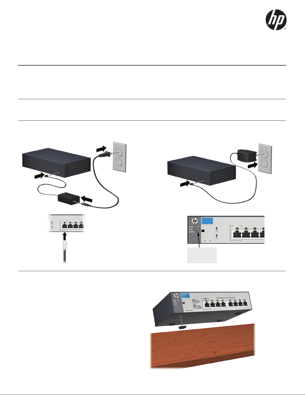
3. Power on and verify that Self-Test completes normally. The switch does not have a power switch. It is powered on
by connecting the AC power adapter supplied with your switch, or by a PoE connection to Port 1 (8G Switch only).
After Self-Test:
Power LED = On
Fault LED = Off
4. Mount the switch. Unplug the AC power from the switch before mounting it.
Table or Desktop Mounting: Attach the four self-
adhesive pads(included in the accessory kit) to the bottom
corners of the switch.
1
Page 2
4. Mount the switch. (continued)
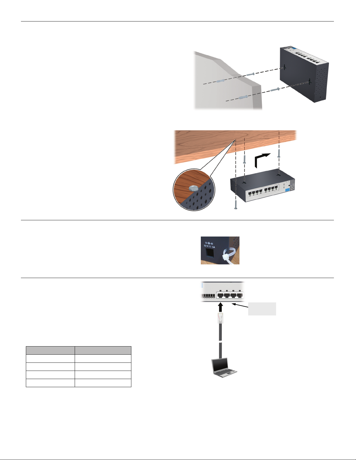
Wall Mounting: Install two 5/8-inch (15.875 mm) Number
12 wood screws, (included) into the mounting surface,
positioned 5.5 inches (140 mm) apart. Use the wall anchors
if necessary. Then, position the switch over the screws and
slide to lock in place.
Important: For wall-mounting, the network ports must be
facing up or down. Do not mount the switch with
ventilation holes facing up or down. (See “Installation
Precautions” on page 4.)
Under-Table Mounting: Install the two screws on the
table bottom similarly to the procedures for wallmounting.
Then, position the switch over the screws and slide to lock
in place. Install the third screw at the side of the switch to
prevent it from sliding out of the locked position, if
necessary.
5. Power on the switch: Follow the same procedures as
in step 3.
It is recommended that you then secure the power cable
with the supplied cable tie.
6. Configure the switch for operation on your
network (minimal configuration).
Using a standard Ethernet cable, connect a PC directly to
any network port on the switch. Then configure the PC’s
IP Address and Subnet Mask to allow it to communicate
with the switch through your PC’s web browser.
Switch factory-default settings:
Parameter Factory Default Setting
Password <blank>
IP address 192.168.2.10
Subnet mask 255.255.255.0
Default gateway not set
Connect to
any port
Modify the switch’s IP configuration to operate in your network. See the example initial configuration page 3.
Note: When you are done with the initial switch configuration, disconnect the LAN cable from your PC and connect the
switch into the network.
Be sure to return your PC to its original network settings before connecting it to your network.
2
Page 3

7. Connect the network cables.
8. (Optional) Lock the Switch: Use a Kensington lock
or similar device (not included) to physically secure the
switch.
Example: Initial Switch Network Configuration using Windows®XP
1. Reconfigure the PC’s IP address and Subnet Mask so that it can communicate with the switch.
a. Click Start > Connect to > Show all connections.
b. Select and right-click Local Area Connection, then click Properties.
c. Scroll and select Internet Protocol (TCP/IP), then click Properties.
Note: Be sure to record all your PC’s current IP settings to be able to restore them later.
d. On the General tab, click Use the following IP address.
e. For IP address, enter an IP address in the same range as the switch’s default IP address. For example, enter 192.168.2.12.
f. For Subnet mask, enter 255.255.255.0, then click OK.
g. Click Close (or OK) to close the Local Area Connection Properties screen.
2. Open your web browser on the PC, and enter the switch factory-default address, http://192.168.2.10, to access the switch’s
web interface.
3. Click Log on to log onto the switch (by default, there is no password).
4. Click Network Setup > Get Connected and configure IP network settings on the switch for operation on your network.
Important: If you enable DHCP on the switch for automatic IP network configuration, at the time of that selection, the
switch must be connected to the same network as the DHCP server. Otherwise, the switch will revert to the 192.168.2.10
address. After automatic IP configuration, you must determine the IP address assigned to the switch. To do this, you will
need to access your DHCP server files, or use LLDP (Link Layer Discovery Protocol) commands on a connected device
(such as another switch).
5. Click Apply on the browser configuration screen to save your settings to retain them when the switch is rebooted.
You are done with initial switch configuration. Disconnect the LAN cable from your PC and connect the switch into the
network.
Be sure to return your PC to its original network settings before connecting it to your network.
3
Page 4

Safety Precautions
To avoid personalinjury or productdamage when installingyour switch, read the installation precautions and guidelines below.
Installation Precautions
Warnings
■ Do not wall-mount any switch without checking for restrictions in the Installation and Getting Started
Guide.
Wall-mount the switch with network ports facing up or down (away from or toward the floor). Do not wallmount the switch with the ventilation holes facing up or down.
Cautions
■ Ensure the power source circuits are properly grounded, thenuse the power cord supplied with the switch to connect
to the AC power source.
■ If your installation requires a different power cord than the one supplied with the switch and/or power supply, be
sure the cord is adequately sized for the switch’s current requirements. In addition, be sure to use a power cord
displaying the mark of the safety agency that defines the regulations for power cords in your country/region. The
mark is your assurance that the power cord can be used safely with the switch and power supply.
■ When installing the switch, the AC outlet should be near the switch and should be easily accessible in case the switch
must be powered off.
■ Ensure the switch does not overload the power circuits, wiring, and over-current protection. To determine the
possibility of overloading the supply circuits, add together the ampere ratings of all devices installed on the same
circuit as the switch and compare the total with the rating limit for the circuit. The maximum ampere ratings are
usually printed on the devices near the AC power connectors.
■ Do not install the switch in an environment where the operating ambient temperature exceeds its specification.
■ Ensure the air flow around the switch is not restricted. Leave at least 3 inches (7.6 cm) for cooling.
For additional Safety and Regulatory information, refer to the Safety and Regulatory documentation included with your switch.
© Copyright 2012 Hewlett-Packard Development Company, L.P.
The information contained herein is subject to change without notice.
Printed in China
June 2012
5998-3195
*5998-3195*
 Loading...