

Page 1

SERVICE MANUAL
HP 16532A
1 GSa/s Di g i t i zing
Oscilloscope
COPYRIGHT HEWLETT-PACKARD COMPANY,
COLORADO SPRINGS DIVISION 1991-1993
1900 GARDEN OF THE GODS ROAD, COLORADO SPRINGS, COLORADO U.S.A.
ALL RIGHTS RESERVED
Manual Part No. 16532-97002 PRINTE D: JULY 1993
Page 2
SAFETY CONSIDERATIONS
GENERAL - This is a Safety Class I instrument ( provided with
terminal for protective earthing).
OPERATION - BEFORE APPLYING POWER verify that the
power transformer primary is matched to the available line
voltage, the correct fuse is installed, and Safety Precautions
are taken (see the following warnings). In addition, note the instrument’s external markings which are described under
"Safety Symbols."
• Ser vicing instructions are for use by service-trained personnel. To avoid dangerous electric shock, do not perform
any servicing unless qua lified to do so.
• BEFORE SWITCHING ON THE INSTRUMENT, the protective earth terminal of the instrument must be connected to
the protective conductor of the (mains) powercord. The
mains plug shall only be inserted in a socket outlet provided with a protective earth contact. The protective action
must not be negated by the use of an e x tension cord
(power cable) without a protective conductor (grounding).
Gr ou nding one conductor of a two-con duc tor outlet is not
sufficie nt protec tion.
• If this instrument is to be e nergized vi a an auto-transformer (for v oltage reduction) make sure the common terminal is connected to the earth terminal of the power
source.
• Any interruption of the protective (grounding) conductor
(ins i de or outside th e instrument) or disconnecting the protective earth terminal will cause a potential shock hazard
that could result in personal injury.
• W henever it is lik ely that the protection has been impaired, the instrument must be made inoperative and be
sec ur ed against any unintended operation.
• Only fuses with the required rated current, voltage, and
specified type (normal blow, time delay, etc.) should be
used. Do not us e repaired fuses or shor t circuited fus eholders. To do so could cause a shock or fire hazard.
• Do not operate the instrument in the presence of flammable gasses or fumes. Operation of any electrical instrument in such an environment constitutes a definite safe ty
hazard.
• Do not in stall substitute parts or perfor m any unauthorized
modification to the instrument.
• A djustments described in the manual are performed with
power supplied to the instrument while protective covers
are r e move d. E ne rgy available at many points may, if contacted, result in personal injury.
• A ny adjustment, maintenance, and repair of the opened instrument under voltage should be avoided as much as
possible, and when inevitable, should be carried out only
by a skilled person who is aware of the hazard involved.
• Capacitors inside the instrument may still be charged
even if the ins trument has been disconnected from its
source of supply.
SAFETY SYMBOLS
Ins tr uction manual sy mbol. The product will be
marked with this symbol when it is necessary for
the user to refer to the instruction manual in order
to protect against damage to the product.
Indicates hazardous voltages
Earth terminal (sometimes used in manual to indicate circuit common connected to grounded
chassis).
The WARNING sign denotes a hazard. It
calls attention to a procedure, practice,
or the like, which, if not correctly performed or adhered to, could result in personal injury. Do not
proceed beyond a WARNING sign until the indicated conditions are fully understood and met.
The CAUTION sign denotes a hazard. It
calls attention to an operating procedure,
practice, or the like, which, if not correctly performed or adhered to, could result in damage to or
destruction of part or a ll of the product. D o not proceed beyond a CAUTION sign until the indicated conditions are fully
understood or met.
SC1D98 4
Page 3

HP 16532A - Table of Contents
CONTENTS
SECTION I
General Informatio n
1-1 . I ntroduction .............................................................................................................................. 1-1
1-2. Module Covered by This Manua l ............................................................................................ 1-1
1-3. S a fe ty R e quirements ............................................................................................................... 1-1
1-4. P roduct Description ................................................................................................................. 1-2
1-5. A ccessories Supplied .............................................................................................................. 1-2
1-6. A ccessories Available............................................................................................................... 1-2
1-7. S pecifications ........................................................................................................................... 1-2
1-8. Operating Characteristics ....................................................................................................... 1-2
1-9. Recommended Test Equipment ............................................................................................. 1-2
SECTION II
Installation
2-1 . I ntroduction ............................................................................................................................. 2-1
2-2. Initial Inspection ...................................................................................................................... 2-1
2-3. P reparation for Use ................................................................................................................ 2-1
2-4. P ower R e quirements .............................................................................................................. 2-1
2-5. S a fe ty R e quirements .............................................................................................................. 2-1
2-6. Module Installation ................................................................................................................. 2-1
2-7. Operating Environment .......................................................................................................... 2-4
2-8. S torage .................................................................................................................................... 2-4
2-9. P a ckaging ............................................................................................................................... 2-4
2-10. Tagging for Service ................................................................................................................ 2-4
SECTION III
Performance Tests
3-1 . I ntroduction .............................................................................................................................. 3-1
3-2. Recommended Test Equipment ............................................................................................. 3-1
3-3. Test Record .............................................................................................................................. 3-1
3-4. P e rformance Test Interval ....................................................................................................... 3-1
3-5. P e rformance Test Procedures ................................................................................................ 3-1
3-6. DC C AL OUTPUT Test ............................................................................................................. 3-2
3-7. A C C AL OUTPUT Test ............................................................................................................. 3-3
3-8. Input Resistance ...................................................................................................................... 3-4
3-9. Voltage Measurement Accuracy ............................................................................................. 3-6
3-10. Offse t A ccuracy ....................................................................................................................... 3-9
3-11. Ba ndwidth ................................................................................................................................ 3-11
3-12. Time Measurement Accuracy .................................................................................................. 3-13
3-13. Trigger Sen s itivity .................................................................................................................... 3-15
v
Page 4

HP 16532A - Table of Contents
SECTION I V
Calibration
4-1 . I ntroduction............................................................................................................................... 4-1
4-2. S a fe ty R e quirements................................................................................................................ 4-1
4-3. Ca libration Interval.................................................................................................................... 4-1
4-4 . M aintaining System Integrity.................................................................................................... 4-1
4-5 . Calibration Protection Switch................................................................................................... 4-1
4-6. Recommended Test Equipment..............................................................................................4-2
4-7 . I ns trument Warmup.................................................................................................................. 4-2
4-8. Ca libration................................................................................................................................. 4-2
4-9 . Setting the PROTECT/UNP ROTECT Switch to UNPROTECT................................................ 4-3
4-10. Equipment Required for Calibration ....................................................................................... 4-4
4-1 1. Loading the D efault Calibration Factors................................................................................. 4-4
4-12. Self Cal Menu Calibrations...................................................................................................... 4-5
4-1 3. Setting the PR O TEC T/UNP ROTECT Switch to PROTECT.................................................... 4-8
4-14. Sealing the Mainframe............................................................................................................. 4-8
Section V
Replaceable Parts
5-1 . I ntroduction .............................................................................................................................. 5-1
5-2. A bbreviations ........................................................................................................................... 5-1
5-3. Replaceable Parts List ............................................................................................................. 5-1
5-4. Ordering Information ............................................................................................................... 5-1
5-5. E xchange Assemblies ............................................................................................................. 5-1
5-6. Direct Mail Order System ........................................................................................................ 5-2
SECTION VI
Service
6-1 . I ntroduction .............................................................................................................................. 6-1
6-2. S a fe ty R e quirements ............................................................................................................... 6-1
6-3. Recommended Test Equipment ............................................................................................. 6-1
6-4. Module Block Diagram and Theory of Operation ................................................................... 6-1
6-5. A ttenuator Theory of Operation............................................................................................... 6-1
6-6. Main A s se mbly Theory of Operation ....................................................................................... 6-1
6-7. S e lf-Tests .................................................................................................................................. 6-4
6-8. Troubleshooting ....................................................................................................................... 6-10
6-9. Oscilloscope Module R e moval and R e placement ................................................................. 6-18
6-10. Trigger Cable Removal and R e placement ............................................................................. 6-20
6-11. Attenuator Removal and Replacement .................................................................................. 6-21
vi
Page 5

HP 16532A - Table of Contents
LIST OF TABLES
TABLE TITLE PAGE
1-1. HP 16532A Specifications........................................................................................................ 1-3
1-2. HP 16532A Operating Characteristics..................................................................................... 1-4
1-3. Recommended Test Equipment..............................................................................................1-9
3-1. P e rformance Test R e cord ........................................................................................................ 3-17
4-1. Ca libration Sequence............................................................................................................... 4-2
5-1. Reference Designator and Abbreviations................................................................................ 5-3
5-2. Replaceable Parts List.............................................................................................................. 5-5
LIST OF FIGURES
FIGURE TITLE PAGE
2-1. E ndplate Overlap - Top Sequence........................................................................................... 2-2
2-2. E ndplate Overlap - Bottom Sequence..................................................................................... 2-3
3-1. Voltage Measurement Accuracy Test........................................................................................ 3-7
4-1. E ndplate Overlap - Top Sequence........................................................................................... 4-3
4-2 . Location of the PROTECT/UNP ROTECT Switch..................................................................... 4-3
4-3 . Default Calibration Dis pla y....................................................................................................... 4-4
4-4. E xt T rig Null Calibration Connections......................................................................................4-7
4-5. E nd of Calibration Display........................................................................................................ 4-8
4-6. E ndplate Overlap - Top Sequence .......................................................................................... 4-8
5-1. Pa rts I de ntification.................................................................................................................... 5-4
6-1. HP 16532A Oscilloscope Block Diagram................................................................................ 6-2
6-2 . Startup Screen.......................................................................................................................... 6-4
6-3. Load Te st S ystem Screen........................................................................................................6-5
6-4. Test System Screen.................................................................................................................. 6-5
6-5. Functional Tests Screen........................................................................................................... 6-6
6-6. Main Test Menu ........................................................................................................................ 6-6
6-7. A /D Test Run Screen................................................................................................................ 6-7
6-8. S top Field.................................................................................................................................. 6-7
6-9. Exit Tes t System Screen..........................................................................................................6-8
6-10. Troubleshooting Flowchart ...................................................................................................... 6-13
6-11. Endplate Overlap - Top Sequence........................................................................................... 6-18
6-12. Endplate Overlap - Bottom Sequence..................................................................................... 6-19
6-13. Oscilloscope Module Exploded View...................................................................................... 6-20
vii
Page 6

TABLE OF CONTENTS
General Informatio n
1-1 . I ntroduction...........................................................................................................................1-1
1-2. Module Covered by Manual.................................................................................................1-1
1-3. S a fe ty R e quirements.............................................................................................................1-1
1-4. P roduct Description..............................................................................................................1-2
1-5. A ccessories Supplied ...........................................................................................................1-2
1-6. A ccessories Available...........................................................................................................1-2
1-7. S pecifications........................................................................................................................1-2
1-8. Operating Characteristics.....................................................................................................1-2
1-9. Recommended Test Equipment ..........................................................................................1-2
Page 7

1-1. Introduction
HP 16532A - General Information
SECTION I
General Information
Th e service policy for this instrument is replacement of defective asse mblies. This service guidel
contains information for finding a defective
assembly by testing and servicing the HP 16532A
1 GS a/s Oscilloscope Module. Also included in
the guide are installation procedures and a list of
recommended test equipment. This guide is
divided into six sections as follows:
I - General Information
II - Installation
III - Performance Tests
IV - C a libration
V- Replaceable Parts
V I - Service
Th e G e ne ra l I nformation S e ction includes safety
requirements, a product description, and a list of
accessories supplied and of accessories available.
Also included are table s lis ting specifications and
operating characteristics, and a list of
recommended test equipment.
To complete the service documentation for your
HP 16500 Logic Analysis System, place this
serv ice manu a l in the 3 - ring binder with your other
logic analysis system Service Guides.
1-2. Mo d ule Covered by This Ma nual
Th e inf ormation covered in this ma n ual is for the
HP 16532A 1 GSa/s Oscilloscope Module.
1-3. Safety Requirements
Specific warnings, cautions, a nd instructions are
placed wherever applicable throughout the
manual. These must be observe d during all
pha ses of opera tion, s ervi ce, and repa i r of the
module. Failure to comply with them violates
safety standards of design, manufa cture, a n d
intended use of this module.
Hewlett-Packard assumes no liability for the failure
of the customer to comply with these safe ty
requirements.
1-1
Page 8

HP 16532A - General Information
1-4. Product Description
The HP 16532A Oscilloscope Module is a 1 GS a /s
digitizing oscilloscope. Some of the main f e atures
are:
• 1 GSa/s digitizing for 250 MHz bandwidth sin-
gle shot analysis.
• 8000 samples per channel.
• Automatic pulse parame te rs , dis plays time be-
tween ma rke rs , acquires until s pecifi e d time
between ma rke rs is captured, performs statistical analys is on time betwee n ma rke rs .
• Lightweight miniprobes.
1-5. Accessories Supplied
Th e following accessories are supplied with the
HP 16532A Oscilloscope module. Quantity one
unless shown otherwise.
• Use r’s Refere nce and Programming R e f er-
ence set
• 24-pin IC test clip (HP 10211A)
• BNC-to-BNC ac coupling capacitor
(HP 10240B)
10:1 Probe:
• 1-MΩ, 7.5- pf miniprobe, 1 m (HP 10435A )
1:1 Probes:
• 40-pf miniprobe, 1 m (HP 10438A)
• 64-pf miniprobe, 2 m (HP 10439A)
• 50-Ω miniprobe, 2 m (HP 10437A)
100:1 Probe:
• 10-MΩ, 2.5- pf miniprobe, 2 m (HP 10440A )
1-7. Specifications
Module specifications are listed in table 1-1. These
specifications are the performance standards
against which the module is tested.
• Service G uide
• HP 10441A 10:1 probes, Qty 2
• Right angle BNC adapters, Qty 2
• BNC miniprobe adapter
• Mas te r- slave trigger cable
• Operating Sys tem Software
1-6. Accessories Available
• 10:1, 100:1, 50 Ω, 10 pf resistive divider probe
set, 1.2 m (HP 10020A)
• BNC-to-BNC cable, 1.2 m (HP 10503A)
1-8. Operating Characteristics
Ta ble 1 - 2 is a listing of the module operating
characteristics. The operating characteristics are
not specifications, but are the typical operating
characteristics included as a dditional information
for the user.
1-9. Recomme nded Test
Equipment
Equipment required to test and maintain the
HP 16532A Oscilloscope Module is listed in table
1-3. Other equi pment may be substituted if it
meets or e xceeds the critical specifications listed
in the table.
1-2
Page 9

HP 16532A - General Information
Table 1-1. HP 16532A S pecifications
HP 16532A SPECIFICATIONS
Type: 2- chann el s imulta ne ous a cquisition
(* ,1)
Bandwidth
Maximum Sample Rate: 1 Gigasample per second
Number of Channels: 2, 4 , 6, 8 simultaneous channels usi ng the s ame time base s etting(s)
OR
Up to 10 chan nels with independent time bases f or e ach pair of channels.
Up to 18 chann e ls with the HP 16501A Expansion Frame.
Rise Time
ADC: 8-bit real time
Vertical Resolution: 8 bits ov er 4 vertica l div i s i ons (± 0.4%)
Waveform Record Length: 8000 points
Time Interval Measurement Accuracy
Vertical (dc) Gain Acc ura c y
DC Offset Accurac y
Voltage Measurement Accuracy
Trigger Sensitivity
: dc to 250 MHz (real time, dc-coupled)
(2)
: 1.4 ns
(*,3,6)
(4)
: ± 1.5% of full scale
(* )
: ± (1.0 % of channel offset + 2.0% of full s cal e )
(* ,5)
: ± [(1.5% of full scale + offset accuracy) + (0.008 x V/div)]
(* )
: dc to 50 MHz: 0.063 x full scale, 5 0 to 250 MHz: 0.125 x full scale
: ± [(0.005% X ∆t)+ (2 x 10
6
−
x delay se tting)+ 150 ps]
Input Coupling: 1 MΩ: ac and dc, 50 Ω: dc only
(*)
Input R (selectable)
: 1 MΩ: ± 1%, 50 Ω: ± 1%
Input C: Approximately 7 pF
___________________________________________________________________________________________
NOTES:
* Specifications (valid within ± 10° C of auto-calibration temperature, excluding bandwidth− see
note 1 for bandwidth specification.)
1. Upper bandwidth reduces by 2.5 MHz for every degree C above 35° C.
=
bandwid th
0.35
1
sample rate
2. Rise time is calculate d from the formula:
3. S pe cification applies to the maximum s ampling rate. At lower rates, the s pecification is:
± [(0.005% x ∆t)+ (2 x 10
= 1.4 x sa mple inte rv a l). Sample interva l is defi ne d as
(t
r
-6
x delay setting) + (0.15 x sa mple interv a l)] for bandwidth limited signals
t
r
4. Vertical gain accuracy decreas es 0.0 8% per degree C from software cal ibra tion temper a ture.
5. D i gitizi ng le vel = (#vertical divisions)(
1
)(
), where LS B = 2
LSB
2
# bits in ADC
1
6. The T ime Inte rval Mea s ure me nt Accuracy deteriorates across multiple modules connected as one
unit with ea ch a dded module.
1-3
Page 10

HP 16532A - General Information
Table 1-2. HP 16532A Operating Characteristics
HP 16532A OPERATING CHARACTERISTICS
VERTICAL (at BNC)
Vertical Sensitivity Range (1:1 Probe):
4 mV/div to 10 V/div in 1-2-4 increments
DC Offset Range (1:1 Probe):
V e rtical Sensitiv ity Availa ble Offse t
4 mV/div to 100 mV/div ± 2 V
> 100 mV/div to 500 mV/div ± 10 V
> 500 mV/div to 2.5 V/div ± 50 V
> 2.5 V/div to 10 V/div ± 250 V
Probe Factors:
Any integer ratio from 1:1 to 1000:1
Maximum Safe Input Voltage:
1 MΩ: ± 250 V [dc + peak ac (< 10 KHz)]
50 Ω: ± 5 VRMS
Channel-to-Channel I solation:
dc to 50 MHz: 40 dB, 50 MHz to 250 MHz: 30 dB
TIM EBASE
Range:
1 ns/div to 5 s/div
Resolution:
20 ps
Delay Pre-trigger Range:
Ti me /div Setting Available Delay
1 µs to 5 s/div -8 x (s/div)
1 ns to 500 ns/div -4 µs
Delay Post-trigger Range:
1-4
Ti me /div Setting Available Delay
100 ms to 5 s/div 2.5 ks
1 µs to 50 ms/div 33,500 x (s/div)
1ns to 500 ns/div 16.7 ms
Page 11

TRIGGERING
Trigger Level Range:
Trigger Modes:
Immediate:
Edge:
Pattern:
HP 16532A - General Information
Table 1-2. HP 16532A Operating Characteristics (cont.)
Within display window (full scale an d offset)
Triggers imme diate ly a f ter a rming condition is met.
Triggers on rising or falling edge of any internal channel or external trigger,
count adjustable f rom 1 to 32,000.
Triggers on ente ring, e xiting, duration greater tha n, duration less than, and
duration in range for a specified pattern of both internal channels an d external
trigger, count adjustable from 1 to 32,000. Duration time range is a djustable
from 20 ns to 160 ms in 10 ns steps. Duration accuracy is approximately ± 3%
± 2 ns.
Auto-Trigger:
If enabled, the module will self-trigger if no trigger condition is found within
approximately 50 ms after arming.
Events Dela y:
Th e trigger can be s et to occur on the nth edge or pattern, as specified by the
user. The number of events (n) can be s et from 1 to 32,000 events. Maximum
count frequency is 7 0 MH z .
Intermodule:
Arms a n other mea sure me nt module or triggers the re a r pane l B NC .
Exte rn a l:
If ena bled, the oscilloscope will trigger on an ECL l ev e l s ignal (-1 . 3 V).
DIGITIZER
Resolution: 8 bits (1 part in 256)
Digitizing Rate: Up to 1 Gigasample per second
Digitizing Technique: Re al-time digitizing; each 8000 samples are acquired on a single acquisition
Acquisition Memory Size: 8000 samples per channel
1-5
Page 12

HP 16532A - General Information
Table 1-2. HP 16532A Operating Characteristics (cont.)
WAVEFORM DISPLAY
Displayed Wavefo rms:
Eight wave f orm windows maximum, with scrolling across 96 wav e f orms.
Display Forma ts:
W aveforms can be di splay ed in an ove rlapping and/or non-ov erla pping format.
Displa y capability of A − B and A+ B is also provided.
Display Resolution:
500 points horizontal, 240 points vertical
DISPLAY M ODES
Normal (Single):
New acquisition replaces old acquisition on screen.
Accu mu l at e:
New acquisition is displayed in addition to previous acquisitions until screen is
erased.
Average:
New a cquisitions are a veraged with old acquisitions, with the updated wav e f orm
displayed until era s e d. M a ximum number of a v e rages is 256.
Overlay:
Up to 8 acquired waveforms from separate channels can be ove rla ye d in the
same display area.
Connect-the-dots:
Provides a displa y of the s ample points connected by straight lines.
Waveform Reconstr uction:
Wh e n the re is insufficient data to fill e v ery horizontal location, a post acquisition
reconstruction filter fills in missin g data points for time bas e < 50 ns/div.
Waveform Math:
1-6
Displa y capability of A − B and A+ B functions is provided.
Page 13

Table 1-2. HP 16532A Operating Characteristics (cont.)
MEASUREMENT AIDS
Time Markers:
Tw o vertical markers, X and O, are provided for mea surements of time and
voltage. Capabilities are: measure voltage at point where X and O markers
cross each a n alog waveform; me asure time f r om trigger to X, trigger to O, and
X to O; automatic marker placement by specifying percentage of edge, edge
number, and rising or falling edge type; run until X to O > than, < than, in
range, and not in range provides selective event search; X to O statistics (mean,
max, an d min) provide analysis of time interval deviation.
Automatic Search:
Se arches for a percentage or an absolute voltage lev el at a positive or ne gative
edge, count adjusta ble from 1 to 100.
Auto Search Statistics:
HP 16532A - General Information
Mea n, maximum, an d minimum values for el apsed time from X to O ma rke rs for
multiple runs. Number of val id runs a n d total number of runs av a i la ble .
Automatic Measurements:
The following pulse parameter mea s ure me nts can be perf ormed automatically:
Freque ncy R is e time + pulse width
Pe riod Fall time − pulse width
V p-p Preshoot V
Overshoot
Grid:
Gr aticules ca n be displaye d i n backrou nd of wa vefor m.
Voltage Markers:
Tw o horizontal marke rs, A an d B, are provided for voltage measure me nts.
Th e se markers can each be placed on any acquisition channel trace. A delta
volt age display pr ovides delta V betwe en ma r k ers on t h e sa me cha nnel or
between two channels .
amplitude
*
(*gives difference between top and base
voltages; only available over bus)
1-7
Page 14

HP 16532A - General Information
Table 1-2. HP 16532A Operating Characteristics (cont.)
SETUP AIDS
Autoscale:
Autoscale s the vertical an d horizontal ra n ges , off s et, and trigger level to display
the input signals. Requires a frequency between 50 Hz and 250 MHz.
Presets:
Scale s the vertical ra n ge, offset, and trigger level to predetermined values for
displaying ECL or T TL waveforms.
Calibration:
V e rtica l, trigger, del a y, and all defaults . C alibration factors stored in NV-RAM on
the circuit board.
Probe Compensation Source:
External BNC su pplies a square wave approximately 0. 0 mV to -800 mV into the
open circuit at approximately 1000 Hz.
OPERATING ENVIRONMENT
Temperature:
Instrument, 0° to 5 5 ° C (+ 32° to 131° F). Probes and cables, 0° to 65° C (+ 32°
to 149° F).
Humidity:
Instrument, u p to 95% relativ e humidity a t + 4 0 ° C (+ 104° F). Recommended
disk media, 8% to 80 % relative humidity at + 4 0° C (+ 104° F).
Altitude:
To 4600 m (15,000 ft).
Vibration
Operation:
Random vibration 5-500 Hz, 10 minutes per a xis , ~ 0 . 3 g (rms).
Non-operating:
Random vibration 5-500 Hz, 10 minutes per a xis , ~ 2 . 41 g (rms); and swept
sine resonant search, 5-500 Hz, 0.75 g (0- peak), 5 minute resona nt dwell @ 4
resonances per axis.
1-8
Page 15

HP 16532A - General Information
Table 1-3. Recommended Test Equipment
EQUIPMENT CRITICAL SPECIFICATIONS RECOMMENDED MODEL USE*
Signal Generator Frequency: 1 - 250 MHz at approx .
170 mV RMS resolution
Output Accuracy: ± 1 dB
1 MHz time bas e accuracy 0.2 5 ppm
Dc Power Supply Range: − 35.000 to + 35.000 Vdc, ± 1 mV HP 6114A P
Digital Multime ter 0.1 mV resolution
Accuracy: better than 0.005%
R esistance mea s u rement: bette r th a n
0.25% accuracy
Power Meter/Sensor 1 - 250 MHz ± 3% accuracy HP 436/8482A P
Power Splitter Outputs differ by < 0.1 5 dB HP 11667B P
Blocking Capacitor 50 Ω BNC (m-to-f), 0.18 µF, ± 200 V HP 10240B P
Adapter 50 Ω BNC (m)(m) HP 1250-1236 C
Adapter 50 Ω Type N(m)- to-B N C (m) HP 1250-0082 P
Adapter 50 Ω BNC(f)-to-Dual Banana Plug HP 1251-2277 P
HP 8656B Option 001 P
HP 3458A P
Adapter 50 Ω Type N(m)-to-BN C (f ) HP 1250-0780 P
Tee Adapter 50 Ω BNC (m)(f)(f ) HP 1250-0781 P,C
Cable Type N(m-to-m) 24- i nch HP 11500B P
Cable 50 Ω BNC (m-to-m) 48-inch HP 10503A P
Cable 50 Ω BNC (m-to-m) 9 inch HP 10502A C
Cable 50 Ω BNC-SMB HP 16532-61601 C
*P= Performance Tests C= Calibrations
1-9
Page 16

1-10
Page 17

TABLE OF CONTENTS
Installation
2-1 . I ntroduction ......................................................................................................................... 2-1
2-2. Initial Inspection .................................................................................................................. 2-1
2-3. P reparation for Use ............................................................................................................. 2-1
2-4. P ower R e quirements .......................................................................................................... 2-1
2-5. S a fe ty R e quirements ........................................................................................................... 2-1
2-6. Module Installation .............................................................................................................. 2-1
2-7. Operating Environment ................................................................................................. ..... 2-4
2-8. S torage ................................................................................................................................ 2-4
2-9. P a ckaging ........................................................................................................................... 2-4
2-10. Tagging for Service ............................................................................................................. 2-4
Page 18

Page 19

HP 16532A - Installation
SECTION II
Installation
2-1. Introduction
This section explains how to initially inspect the
HP 16532A Oscilloscope Module, then how to
prepare it for use, storage, and shipment. Also
included are procedures for module installation.
2-2. Initial Inspection
Inspect the shipping container for damage. If the
shipping container or cushioning material is
damaged, it should be kept until the contents of
the shipment have been checked for
completeness and the module has been checked
mechanically and electrically. T h e contents of the
shipment should be as lis te d in the "Accessories
Supplie d" par agraph l ocated in Secti on I.
Procedures for checking electrical performance
are in Section III. If the contents of the container
are incomplete, there is mechanical damage or
defect, or the instrume nt does not pass the
performance tests, notify the nearest
Hewlett-Packard sales office.
2-4. Power Requirements
All power supplies required for operating the
HP 16532A Oscilloscope Module are supplied to
the module through the backplane connector in
the mainfra me .
2-5. Safety Requirements
Specific warnings, cautions, a nd instructions are
placed wherever applicable throughout the
manual. These must be observe d during all
pha ses of opera tion, s ervi ce, and repa i r of the
module. Failure to comply with them violates
safety standards of design, manufa cture, a n d
intended use of this module.
Hewlett-Packard assumes no liability for the failure
of the customer to comply with these safe ty
requirements.
2-6. Module Installation
If the shipping container is damaged, or the
cushioning material shows signs of stress, notify
the carrier as w e ll a s the Hewlett-P a ckard sa l e s
office. Keep the shipping material so the carrie r
can inspect it. Th e H e wle tt-P a ckard office will
arrange for repair or replacement at
Hewlett-Packard’s option without waiting for claim
settlement.
2-3. Preparation for Use
Rea d the Safety Considerations in the front of
this man u al and in Section I be f or e ins talling
or operating this module.
Do not inst all, remove , or replace the module
in the instrument unless the instrument power
is turned off.
The HP 16532A Oscilloscope Module will take up
one slot in the card cage. For ev e ry a dditional
HP 16532A Oscilloscope Module you install, you
will need an a dditional slot. Th e y may be insta lle d
in any slot and in any order. The install a tion
procedure for the module is continued,
step-by-step, on the next page.
2-1
Page 20
HP 16532A - Installation
Module Insta llation (cont. )
The effects of ELECTR OST ATIC D ISCHARG E can damage electronic components. U se grounded wrist straps and mats when you are performing any kind of
service to this module.
Installation Considerations
• The HP 16532A Oscilloscope Modules can be installed in any available card slot.
• For multiple modules connected as one unit, the ma s te r card must be placed in the s lot above the
expander cards. The ma s ter card and expander cards must be in adjoining slots.
• Cards or filler panels below the e mpty slots intended for module installation do not have to be re-
moved to install a module above them.
Proced u r e:
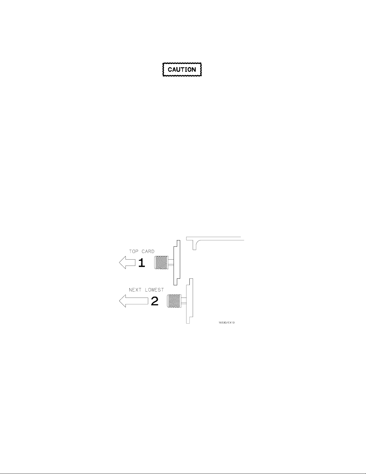
1. T urn i ns trume nt power switch off, unplug power cord and disconnect any input connections.
2. Starting from the top, loosen the thumb screws on the fille r pane ls and cards.
3. Starting from the top, begin pulling out the cards and filler panels halfway. See figure 2-1.
Figure 2-1. Endplate Ov erlap - Top Sequence
2-2
Page 21
HP 16532A - Installation
4. S lide the oscilloscope module into the card cage approximately halfway.
5. If you hav e more oscilloscope cards to install, slide them into the card cage approximately halfway.
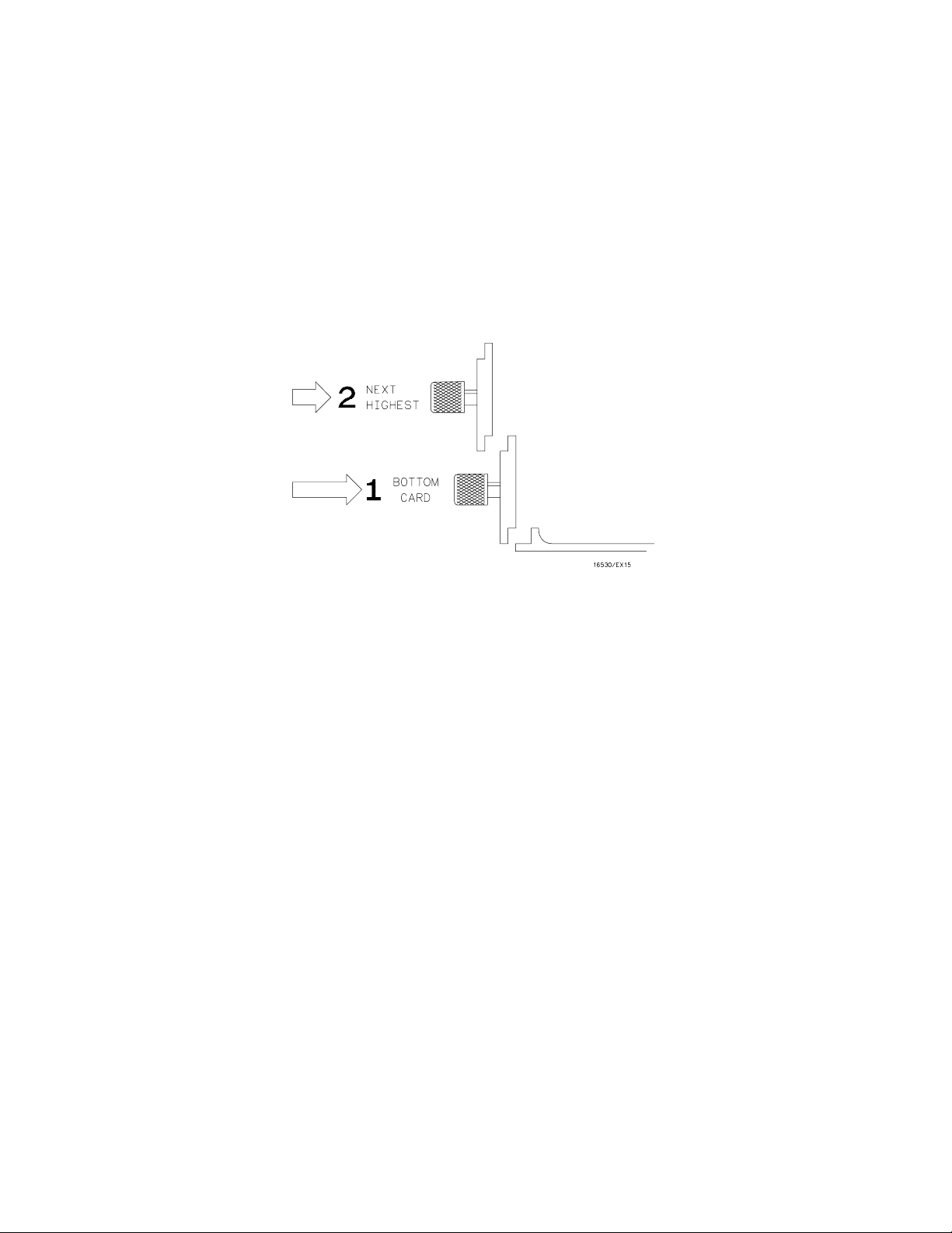
6. F irmly s eat the bottom card into the backplane connector. Keep applying pressure to the center
of the card endplate while tightening the thumb screws finger tight.
7. Repeat step 6 for all cards and filler panels in a bottom-to-top order. See figure 2-2.
8. A ny fille r pane ls tha t a re not used should be kept for future use. Fille r pane ls must be ins t alle d i n all
unused card slots for correct air circulation.
F igure 2-2 . Endplate Overlap - Bottom Sequence
2-3
Page 22

HP 16532A - Installation
2-7. Operating Environment
Th e operating env ironment is lis te d in table 1-2 of
Se ction I of this manu a l. N ote s h ould be made of
the non-condensing humidity limitation.
Condensa tion within the instrume nt can cause
poor oper ation or malfun ct ion . Protect i on should
be provided against internal condensation.
The HP 16532A Oscilloscope Module will operate
at all specifications within the te mpera ture an d
humidity range giv en in table 1-2. H owe ver,
reliability is enhanced when operating the module
within the following ranges.
• Temperature: + 20 °C to + 35 °C (+ 68 °F to
+ 95 °F)
• Humidity: 20% to 80% non-condensing
2-8. Storage
T h e module m ay be s tor e d or shippe d i n
environments within the following limits:
2-9. Packaging
The following general instructions sh ould be us ed
for repacking the module with commercially
availa ble ma teria ls .
• Wrap the module in antis tatic plastic.
• Use a strong shipping container. A double-
walled carton made of 350-lb test material is
adequate.
• Use a layer of shock-absorbing material 70 to
100 mm (3- to 4-inch) thick around all sides of
the module to provide firm cushioning and to
prevent movement within the container.
• Seal the shipping container securely.
• Mark the shipping container FRAGILE to en-
sure proper handling.
• In any correspondence, refer to the module
by its model number and serial number.
• Temperature: − 40 °C to + 75 °C
• Humidity: Up to 90% at 65 °C
• Altitude: Up to 15,300 meters (50,000 feet)
The module should also be protected from
temperature extremes which cause condensa tion
on the instrument.
2-10. Tagging for Service
If the module is to be shipped to a
Hewlett-Packard sales office for service or repair,
attach a tag showing owner (with address),
complete se ria l number, a n d a des cription of the
service required.
2-4
Page 23

TABLE OF CONTENTS
Performance Tests
3-1 . I ntroduction ......................................................................................................................... 3-1
3-2. Recommended Test Equipment ........................................................................................ 3-1
3-3. Test Record ......................................................................................................................... 3-1
3-4. P e rformance Test Interval .................................................................................................. 3-1
3-5. P e rformance Test Procedures ........................................................................................... 3-1
3-6. DC C AL OUTPUT Test ........................................................................................................ 3-2
3-7. A C C AL OUTPUT Test ........................................................................................................ 3-3
3-8. Input Resistance ................................................................................................................. 3-4
3-9. Voltage Measurement Accuracy ........................................................................................ 3-6
3-10. Offse t A ccuracy .................................................................................................................. 3-9
3-11. Ba ndwidth ........................................................................................................................... 3-11
3-12. Time Measurement Accuracy.............................................................................................. 3-13
3-13. Trigger Sen s itivity ............................................................................................................... 3-15
Page 24

Page 25

HP 16532A - Performance Tests
SECTION III
Pe rformance Tests
3-1. Introduction
Th e procedures in this section test the
oscilloscope module’s electrical performance
using the specifications listed in Se ction I as the
performance standards. All tests can be
performed without access to the inte rior of the
instrument. At the end of this section is a f orm that
can be used as a record of performance test
results.
3-2. Recomme nded Test Equipment
Equipment recommended for performance tests is
listed in table 1-3. Any equipment that satisfies the
critical specifications given in the ta ble ma y be
substituted for the re commended models .
3-3. Test Record
R esults of performance tests ma y be ta bula te d on
the Performance Test Record (table 3-1) at the end
of the procedures. The test record lists all of the
tested spe cifications an d their acceptable limits.
Th e re s ults re corded on the test record may be
used for comparison in periodic maintenance a nd
troubleshooting or after repairs a n d adjustments
have been made.
3-4. Performance Test Interval
Pe riodic performance verification of the
HP 16532A Oscilloscope Module is required at
one-yea r inte rv als. Th e instrument’s performance
should be verified after it has been serviced, or if
improper operation is suspected. Calibration
sh ou ld be performe d before any performance
verif ication checks.
3-5. Performance Test Procedures
Al l perform a n ce tes ts should be performed at the
environmental opera ting temperature of the
instrument, af te r a 30-minute w a rmup period.
3-1
Page 26

HP 16532A - Performance Tests
3-6. DC CAL OUTPUT Test
Th e DC CAL OUTPUT port on the rear pane l is used for instrument cali bration an d probe calibration.
Th ough calibrator accuracy is not specified in the performance specifications, it must be within limits in order t o p rovi de accurat e calibration.
Test Limits:
5.000 V ± 10 mV
Equipment Required:
The f ollowing equipment is required for the test.
Recommended
Equipment Required Critical Specification
Model/ Part Number
Digital Multime te r
Cable
Adapter
Procedure:
1. Us e the BNC-to-bana n a a da pter to connect the BNC cable between the multime te r a n d the oscillo-
scope module DC CAL OUTPUT connector.
2. On the oscilloscope module set the following parameters in the order given:
Menu Selection Setting
Calibration Mode
3. The DVM should read close to 0.0000 V. Record the reading to four decimal places.
V1 = __________ .
0.1 mV resolution, better than 0 .005% accuracy
50 Ω BNC (m to m) 48- in ch
50 Ω BNC (f) to Dual Banana Plug
Service Calibration
Procedure
DC Volts
DC Cal BNC
0 V
HP 3458A
HP 10503A
HP 1251-2277
4. In the Calibration menu se t the DC V olts to 5 V.
5. The DVM should read close to 5.0000 V. Record the reading to four decimal places.
V2 = __________ .
6. In the Calibration menu se t the DC V olts to 0 V.
7. Subtract V1 from V2. The difference should be between 4.990 and 5.010 V. Record the reading in
the performance test record.
3-2
Page 27

HP 16532A - Performance Tests
3-7. AC CAL OUTPUT Test
Th e AC CAL OUTPU T port on the rear pane l is used for instrument cali bration an d probe compensation.
Th ough calibrator accuracy is not specified in the performance specifications, it must be within limits in order t o p rovi de accurat e calibration.
Test Limits:
1000 Hz ± 10%, 0.8 V p_p ± 10%
Equipment Required:
The f ollowing equipment is required for the test.
Recommended
Equipment Required Critical Specification
Cable 50 Ω BNC (m to m) 48-inch HP 10503A
Model/ Part Number
Procedure:
1. Use the BNC cable to connect the AC C AL OUT PUT to channel 1 input of the oscilloscope module.
2. On the oscilloscope module set the following parameters in the order given:
Menu Selection Setting
Calibration
Channel
3. In the Calibration menu select AUTOSCALE.
4. In the Auto-Meas ure me nu verify that the wa v eform is approximately 0 . 8 Vp_ p at a pproximately
1000 Hz. Record the reading in the performance test record.
Mode
Procedure
Signal
Coupling
Probe
Service Calibration
Oscillator Output
Probe Compensation
1 MΩ/DC
1:1
3-3
Page 28

HP 16532A - Performance Tests
3-8. INPUT RESISTANCE
This tes t verifies the input resistance of the oscilloscope module. A four-wire meas ure me nt is us ed for accuracy at 50 Ω.
Specification:
1 M Ω ± 1% and 50 Ω ± 1%
Equipment Required:
The f ollowing equipment is required for the test. Procedures are base d on the model or part numbers recommended.
Recommended
Equipment Required Critical Specification
Model/ Part Number
Digital Multime te r
Cables (2)
Adapter
Adapte rs ( 2 )
Procedure:
1. S et up the multimeter to make a 4- wire re s is ta nce me asurement.
2. Us e the B N C - to-banana adapters to connect one end of each BNC cable to the 4-wire re s is ta nce
connections on the multimete r, a n d connect the free e n ds of the cable s to the BNC T ee.
3. Connect the male end of the BNC tee to the channel 1 input of the oscilloscope module. Set up the
oscilloscope module according to the following parameters in the order given:
Menu Selection Setting
Channel
Meas ure res is tance (4- wire ) better than 0.2 5 %
accuracy
50 Ω BNC (m to m) 48 - i nch
50 Ω BNC Tee (m)(f)(f)
50 Ω BNC (f) to Dual Banana Plug
Input
Probe
V/Div
Offset
Coupling
1
1:1
20 mV
0 V
50 Ω / DC
HP 3458A
HP 10503A
HP 1250-0781
HP 1251-2277
Trigger
3-4
Mode
Immediate
Page 29

HP 16532A - Performance Tests
4. Select RUN - SINGLE . The clicking of attenuator relays sh ould be audible. Verify res is tance rea dings on the digital multimeter of 50 Ω ± 0.5 Ω (49.5 to 50.5 Ω).
5. In the Channel menu change the Coupling field to 1 MΩ/DC.
6. S e l ect RUN. The clicking of attenuator relays should be audible. Verify resistance readings on the
digital multimeter of 1 MΩ ± 10 kΩ (0.990 to 1.010 MΩ).
7. In the Channel menu change the Coupling field to 50 Ω/DC and V/Div to 200 mV/Div. Repeat steps
4 through 6.
8. In the Channel menu change the Coupling field to 50 Ω /DC and V/Div to 1 V/Div. Repeat steps 4
through 6.
9. In the Channel menu change the Coupling field to 50 Ω /DC and V/Div to 4 V/Div. Repeat steps 4
through 6.
10. Connect the male end of the BNC tee to the channel 2 input of the oscilloscope module.
11. Repeat ste ps 3 through 9 for channel 2 , r e placing channe l 1 with channel 2 w h e r e applicable.
Note
If a reading is not within limits, then the attenua tor for the out-of-bounds channel
shou ld be r eplaced. See "Serv ice" in Section VI.
3-5
Page 30

HP 16532A - Performance Tests
3-9. VOLTAGE MEASUREMENT ACCURACY
Thi s te st verifie s the DC voltage me asurement a ccuracy of the instrume nt. This procedure use s a dual cursor measureme nt that nullifies offse t e rror, resulting in the following measure me nt:
± [(1.5% of full s cale) + (0.016 x V/div)].
Specification:
± [(1.5% of full s cale + offset accuracy) + (0.008 x V/div)]
Equipment Required:
The f ollowing equipment is required for this test. Procedures are bas ed on the model or part numbers recommended.
Recommended
Equipment Required Critical Specification
Model/ Part Number
DC Power Supply
Digital Multime te r
Cable
Adapter
(cable to power supply)
Adapter
Blocking Capacitor
-14 Vdc to + 14 Vdc, 0.1 mV resolution
Better than 0.1% accuracy
50 Ω BNC (m to m) 48-i nch
50 Ω BNC (f) to Dual Banana Plug
50 Ω BNC tee (m)(f)(f)
50 Ω BNC (m to f) 0.18 µF, 200 V
HP 6114A
HP 3458A
HP 10503A
HP 1251-2277
HP 1250-0781
HP 10240B
3-6
Page 31

HP 16532A - Performance Tests
Proced ure:
1. Using a BNC adapter, connect one end of the cable to the power supply. Connect the BNC tee,
the blocking capacitor, and the s h orting endcap to the other end of the cable. R efer to figure 3-1.
Figure 3-1 . Voltage Measurement Accuracy Test
2. In the Wav e form Selection menu delete channel 2. If channel 1 is not inserted, insert channel 1. Set
the following parameters in the order given.
Menu Selection Setting
Channel
Trigger
Display
Input
Probe
Coupling
s/Div
Mode
Mode
Average #
Grid
Markers
1
1:1
1 MΩ / DC
500 ns
Immediate
Average
8
On
On
Set the C ha nnel
result.
Coupling
field to 1 MΩ/DC or damage to the equipment will
3-7
Page 32

HP 16532A - Performance Tests
Use the f ollowing table for steps 3 through 9.
V/Div Offset Supply Upper Limit Lower Limit
4 V/Div
1 V/Div
400 mV/Div
40 mV/Div
40 mV/Div
400 mV/Div
1 V/Div
4 V/Div
3. With the power supply disconnected from the channel input, se t the C h a nn e l me nu to the V/Div
range and offset values shown in the first line of the table.
4. On the oscilloscope, select RUN - REPETITIVE and wait for approximately fiv e seconds, then select
STOP. Read the voltage displaye d under the chan nel label on the lef t of the dis play. Enter this
value on the performance test record in the "Ze r o Input" column.
5. Set the power supply to the first supply value listed in the table. Connect the power supply to the
channel input as s hown in figure 3 - 1 .
6. On the oscilloscope, select RUN - REPETITIVE and wait for approximately fiv e seconds, then s elect
STOP. Read the voltage displaye d under the chan nel label on the lef t of the dis play. Enter this
value on the pe rformance te s t re cord in the "Measured" column.
7. To obtain the tes t re s ults , subtract the Zero Input voltage from the Measured voltage listed in the
performance test record. For ex a m ple: (M easured) - (Z ero Input) = (Actual). When calculating the
results, observ e the plus or minus value of the v oltage measurements . Record the results in the pe rformance test record in the "Actual" column.
-7.0 V
-1.75 V
-700.0 mV
-70.0 mV
70.0 mV
700.0 mV
1.75 V
7.0 V
-14.0 V
-3.50 V
-1.40 V
-140.0 mV
140.0 mV
1.40 V
3.50 V
14.0 V
-13.7 V
-3.43 V
-1.37 V
-137.0 mV
143.0 mV
1.43 V
3.57 V
14.3 V
-14.3 V
-3.57 V
-1.43 V
-143.0 mV
137.0 mV
1.37 V
3.43 V
13.7 V
8. Repeat ste ps 3 through 8 for the second line of the table, then f or the res t of the line s of the ta ble f or
channel 1.
9. In the Wav e form Selection menu, select Input channel 2. Delete channel 1 and insert channel 2. Repeat steps 2 through 8 for channe l 2, replacing channel 1 with channe l 2 where applicable.
3-8
Page 33

HP 16532A - Performance Tests
3-10. OFFSET ACCURACY
This test verifies the offset accuracy.
Specification:
± (1.0% of chann e l offset + 2.0% of full scale)
Equipment Required:
The f ollowing equipment is required for the test. Procedures are base d on the model or part numbers recommended.
Recommended
Equipment Required Critical Specification
Model/ Part Number
DC Power Supply
Digital Multime te r
Cable
Adapter
Procedure:
Zero-Input Offset
1. Disconnect all cables and probes from the oscilloscope inputs. In the Waveform Selection menu delete channel 2. If channel 1 is not inserted, insert channel 1. Then set up the oscilloscope module
according to the following parameters in the order given:
Menu Selection Setting
Channel
− 35.000 to + 35.000 Vdc, ± 1 mV resolution
Better than 0.1% accuracy
50 Ω BNC (m to m) 48-i nch
50 Ω BNC (f) to Dual Banana Plug
Input
Probe
v/Div
Offset
Coupling
s/Div
1
1:1
4 V
0 V
1 MΩ / DC
500 ns
HP 6114A
HP 3458A
HP 10503A
HP 1251-2277
Trigger
Display
2. With the DC power supply disconnected from the channel input, make sure the m a rke rs are ne ar
the center of the display.
Mode
Mode
Average #
Grid
Markers
Immediate
Average
32
On
On
3-9
Page 34

HP 16532A - Performance Tests
3. Select RUN - REPETITIVE. Wait approximately 1 5 seconds (avera ging complete), then select
ST OP. The display should read 0.00 V ± 320.0 mV as read from the markers voltage field. Record
the reading in the performance test record.
4. In the Channel menu, change the vertical sensitivity to 1 V/Div. Select RUN - REPETITIVE and wait
approximately 15 s econds (ave ra ging complete), then select ST O P. Th e displa y s h ould rea d 0. 00 V
± 80.0 mV. Record the reading in the performance test record.
5. In the Channel menu, change the vertical sensitivity to 100 mV/Div. Select RUN - REPETITIVE and
wait approximately 15 seconds (avera ging complete), then select ST O P. Th e displa y s h ould rea d
0.00 V ± 8.0 mV. Record the reading in the performance test record.
6. In the Channel menu, change the vertical sensitivity to 10 mV/Div. Select RUN - REPETITIVE and
wait approximately 15 seconds (avera ging complete), then select ST O P. Th e displa y s h ould rea d
0.00 V ± 800.0 µV . Record the reading in the performance test record.
DC Input Offset
Set the C ha nnel
Coupling
field to 1MΩ / DC or damage to the equipment will
result.
7. Use the BNC-to-banana adapter to connect the BNC cable between the power supply and channel
1 input. Monitor the power supply using a voltmete r.
8. Use the following table for the next steps:
V/Div Offs et Supply Min Max
1 V/Div
100 mV/Div
20 mV/Div
20 mV/Div
100 mV/Div
1 V/Div
9. In the Channel menu se t the V/Div range and offset per the first line of the table. Set the power
supply per the first line of the table.
10. On the oscilloscope, select RU N - REPETITIVE and wait approximately 15 seconds (avera ging
complete), then ST OP.
− 35.00 V
− 10.00 V
− 2.00 V
+ 2.00 V
+ 10.00 V
+ 35.00 V
− 35.00 V
− 10.00 V
− 2.00 V
+ 2.00 V
+ 10.00 V
+ 35.00 V
− 35.4 V
− 10.1 V
− 2.02 V
+ 1.98 V
+ 9.90 V
+ 34.6 V
− 34.6 V
− 9.90 V
− 1.98 V
+ 2.02 V
+ 10.1 V
+ 35.4 V
11. Read the voltage from the marke rs v oltage f ield. It should be within the limits given in the table. R ecord the reading in the performance test record.
12. Repeat steps 7 through 10 for the remaining lines of the table using the V/Div range, offse t, a n d supply voltages given in the table.
13. In the Channel menu sele ct channel 2. In the Waveform Selection menu delete channel 1 and insert
channel 2.
14. Repeat ste ps 1 through 12 for channe l 2, replacing channel 1 with channe l 2 where a pplicable .
3-10
Page 35

HP 16532A - Performance Tests
3-11. BANDWIDTH
This tes t checks the bandwidth of the oscilloscope module.
Specification:
Bandwidth (dc coupled) dc to 250 MHz
Equipment Required:
The f ollowing equipment is required for this test. Procedures are bas ed on the model or part number recommended.
Recommended
Equipment Required Critical Specification
Model/ Part Number
Signal Generator
Powe r Meter/Sensor
Power Splitter
Cable
Adapter
Procedure:
1. With the N cable, connect the si gna l ge n e r a tor to the power splitter in put. C onn e ct the power
sens or to one output of the power splitter.
2. U s i ng a n N- to-B N C adapter, connect the other power splitter output to the Channel 1 in put of the
oscilloscope module.
3. In the Waveform Selection menu delete channel 2. If channel 1 is not inserted, insert channel 1.
Set the following parameters.
Menu Selection Setting
1 - 250 MHz at approx 170 mVrms
1 - 250 MHz ± 3 % accur acy
Out put s diffe r by < 0.1 5 dB
Ty pe N (m to m) 2 4-inch
50 Ω Type N (m) to BN C (m)
HP 8656B
HP 436/8482A
HP 11667B
HP 11500B
HP 1250-0082
Channel
Trigger
Display
Input
Probe
v/Div
Offset
Coupling
s/Div
Mode
Level
Mode
Average #
Grid
Markers
1
1:1
80 mV
0 V
50 Ω / DC
200 ns
Edge
0 V
Average
32
On
Off
3-11
Page 36

HP 16532A - Performance Tests
4. Set the signal generator for 1MHz at − 2.4 dBm. On the oscilloscope, select RUN - REPETITIVE. The
signal on the scree n s h ould be two cycles a t thre e divisions amplitude.
5. After the measurement settles (averaging complete, about 15 seconds), select STOP. In the
Auto-Me asure menu note the V
reading. V
p-p
= __________ mV.
1MHz
6. S e t the power me ter C a l Factor % to the 1MHz va l ue from the calibration chart on the power splitter.
Then press dB[REF] to set a 0 dB reference.
7. Change the signal generator to 250 MHz. Set power meter Cal Factor % to the 250 MHz value from
the chart.
8. A djust the s i gnal gen e ra tor amplitude for a power rea ding as close a s possi ble to 0. 0 dB[REL].
Reading = __________ dB.
9. Se t the oscilloscope s/Div for 2 ns/Div and select RUN- REPETITIVE.
10. After the measurement settles (averaging complete), select STOP. In the Auto-Measure menu note
the V
reading. V
p-p
= ________mV.
250MHz
11. Calculate the re s ponse us in g the formula:
V
250
response (dB
) = 20 log
10
Mhz
1
MHz
= 20
V
(_____) = ______
log
10
dB
12. Correct the result from step 1 1 with any diffe re n ces in the power m e te r f r om ste p 8. O bserve si gns.
For example:
R esult from step 1 1 = − 2.3 dB
Pow er mete r r eading = − 0.2 dB[RE L]
then true re s ponse = (− 2.3) − (− 0.2) − 2.1dB
(__________) − (__________) = ____________ dB
13. The result fr om ste p 1 2 should be ≤ − 3.0 dB. Record the result in the Performance Test Record.
14. In the Channel menu select channel 2. In the Waveform Selection menu delete channel 1 and
insert channel 2.
15. Repeat ste ps 2 through 14 for channe l 2, replacing channel 1 with channe l 2 where a pplicable .
Note
F a ilure of the bandwidth test can be caused by a fa u lty at tenua tor or main
assembly.
3-12
Page 37

HP 16532A - Performance Tests
3-12. TIME MEASUREMEN T ACCURACY
This te s t us e s a precise frequency source to check the accuracy of time measurement functions.
Specification:
−
± [(0.005% x ∆t) + (2 x 10
Equipment Required:
The f ollowing equipment is required for this test. Procedures are bas ed on the model or part number recommended.
Equipment Required Critical Specification
6
x delay se tting) + 150 ps]
Recommended
Model/ Part Number
Signal Generator
Cable
Adapter
200 MHz, timebase accuracy 0.25 ppm
50 Ω BNC (m to m) 48-inch
50 Ω Type N (m) to BN C (f)
HP 8656B Opt. 001
HP 10503A
HP 1250-0780
Procedure:
1. Set the signal generator to 181.81818 MHz (5.5 ns period) and approximately 600 mV rms.
2. Use the N-to-BNC adapter to connect the cable to the signal generator. Connect the free end of the
BNC cable to the channel 1 input.
3. In the Wav e form Selection menu delete channel 2. If channel 1 is not inserted, insert channel 1. Set
the following parameters in the order given:
Menu Selection Setting
Channel
Input
Probe
v/Div
Offset
Coupling
s/Div
1
1:1
400 mV
0.0 V
50 Ω / DC
2.00 ns
Trigger
Display
Mode
Source
Level
Slope
Mode
Grid
Edge
Chan 1
0.0 V
Positive
Normal
On
3-13
Page 38

HP 16532A - Performance Tests
4. Se le ct the Markers Auto menu, and set the following parameters:
Menu Selection Setting
Markers
Auto
5. Se le ct DONE. On the oscilloscope module select RUN - REPETITIVE. If the waveform is clipping,
reduce the signal ge n e ra tor output voltage level until the waveform no longer clips. All ow the oscilloscope module to run approximately two minutes, the n s elect ST O P.
6. In the statistics fiel d, check to see tha t the M EAN X-O fie l d is a pproximately 5.500 ns. Check that
both the MIN X -O and the MA X X-O a re within 150 ps of the MEAN X-O. Record the results in the
performance test record.
7. Se le ct the Markers Auto menu, and set the following parameters:
Menu Selection Setting
X →
O→
Statistics
Set on cha n 1
at Level 50%
Slope Positive
Occur 1
Set on cha n 1
at Level 50%
Slope Positive
Occur 2
On
Markers
Auto
8. Sele ct DONE. In the Display menu, set MODE AVERAGE #8 and DEL AY 99.00 ns. Select R U N-REPE TITIV E and allow the oscilloscope module to run approximately two minutes. Select ST O P.
9. In the statistics fiel d, check to see tha t the M EAN X-O fie l d is a pproximately 99.000 ns. Check that
both the MIN X -O and the MA X X-O a re within 155 ps of the MEAN X-O. Record the results in the
performance test record.
X →
O→
Statistics
Manual
Set on cha n 1
at Level 50%
Slope Positive
Occur 1
On
Note
Failure of the time measurem ent accuracy test can be caused by a defective
main assem bly.
3-14
Page 39

HP 16532A - Performance Tests
3-13. TRIGGER SENSITIVITY
Th is te s t checks chan ne l triggers for sensitivity a t rate d ban dwidth.
Specification:
dc to 50 MHz : 0.063 x full scale (0.25 division)
50 to 250 MHz : 0.125 x full scale (0. 5 divis i on)
Equipment Required:
The f ollowing equipment is required for this test. Procedures are bas ed on the model or part number recommended.
Recommended
Equipment Required Critical Specification
Model/ Part Number
Signal Generator
Cable
Adapter
50 and 250 MHz, 30-80 mV
50 Ω BNC 48-inch
50 Ω Type N (m) to BN C (f)
rms
output
HP 8656B Opt. 001
HP 10503B
HP 1250-0780
Procedure:
1. In the Wav e form Selection menu delete channel 2. If channel 1 is not inserted, insert channel 1. On
the oscilloscope module set the following parameters in the order given:
Menu Selection Setting
Channel
Trigger
Input
Probe
v/Div
Offset
Coupling
s/Div
Mode
Source
Level
1
1:1
400 mV
0 V
50 Ω / DC
20 ns
Edge
Chan 1
0 V
Display
Mode
Average #
Grid
Markers
Average
8
On
Off
2. With an N- to-B N C adapter and BNC cable, connect the signa l ge n e r a tor to channe l 1 input.
3-15
Page 40

HP 16532A - Performance Tests
3. Se t the signal generator for a 50 MHz a nd 35 mV rms signal. On the oscilloscope module select
RUN - REPETITIVE.
4. In the Auto-Measure menu read V
close to and not more than 100 mV
. Adjust the signal generator output level so that the signal is
p_p
.
p_p
5. In the Trigger menu a djust the trigger lev el for a stable displa y. The test passe s if the trigger is stable. Record whether the trigger is sta ble or is n ot stable.
6. On the oscilloscope module select STOP. Se t the signal generator frequency to 250 MHz and
70 mV rms signal level.
7. In the Channel menu change s/Div to 5 ns/Div and select RUN.
8. In the Auto-Measure menu read V
close to and not more than 200 mV
. Adjust the signal generator output level so that the signal is
p_p
.
p_p
9. In the Trigger menu a djust the trigger lev el for a stable displa y. The test passe s if the trigger is stable. Record whether the trigger is sta ble or is n ot stable in the performance te s t re cord.
10. On the oscilloscope module select STOP. In the Channel menu sele ct channel 2. In the Trigger
menu select Source channel 2. In the Waveform Selection menu delete channel 1 and insert
channel 2.
11. Repeat ste ps 1 through 9 for channel 2 , r e placing channe l 1 with channel 2 w h e r e applicable.
Note
Failure of the trigger sensitivity t est can be caused by a defective m ain
assembly.
3-16
Page 41

HP 16532A - Performance Tests
Hewlett-Packard
Table 3-1. Performance Test Record
Tested by ______________________________
Model 16532A
Oscilloscope Module
Serial No.:
____________________
R ecommended Pe rf ormance
V e rif ication Inte rv a l:
12 M onths
Work Order No. _________________________
Date Tested ____________________________
Paragraph No. Test Results
3-6 DC CAL OUTPUT
5.000Vdc
3-7 AC CAL OUTPUT
3-8 Input Resistance
0.8Vp_p
1000Hz
Ω± 0.5Ω (49.5 to 50.5Ω)
50
1M
Ω± 10KΩ (0.990 to
1.010M
± 10mV
± 10%
± 10%
Ω)
Minimum Maximum Actual
4.990Vdc 5.010Vdc ____________Vdc
Minimum Maximum Actual
0.72Vp_p 0.88Vp_p ____________Vp_p
Minimum Maximum Actual
900Hz 1100Hz ____________Hz
Channel 1 Reading
Ω @ 20mV/Div _____________Ω
50
1M
Ω @ 20mV/Div _____________Ω
Ω @ 200mV/Div _____________Ω
50
1M
Ω @ 200mV/Div _____________Ω
50
Ω @ 1V/Div _____________Ω
Ω @ 1V/Div _____________Ω
1M
50
Ω @ 4V/Div _____________Ω
1M
Ω @ 4V/Div _____________Ω
3-9 Voltage Measurement Accuracy
Upper Limit Lower Limit
-13.7V -14.3V
-3.43V -3.57V
-1.37V -1.43V
-137.0mV -143.0mV
143.0mV 137.0mV
1.43V 1.37V
3.57V 3.43V
14.3V 13.7V
Channel 2 Reading
50
Ω @ 20mV/Div _____________Ω
1M
Ω @ 20mV/Div _____________Ω
50
Ω @ 200mV/Div _____________Ω
Ω @ 200mV/Div _____________Ω
1M
50
Ω @ 1V/Div _____________Ω
1M
Ω @ 1V/Div _____________Ω
Ω @ 4V/Div _____________Ω
50
1M
Ω @ 4V/Div _____________Ω
Channel 1
Zero Input Measured Actual
__________ __________ __________V
__________ __________ __________V
__________ __________ __________V
__________ __________ __________mV
__________ __________ __________mV
__________ __________ __________V
__________ __________ __________V
__________ __________ __________V
3-17
Page 42

HP 16532A - Performance Tests
Ta ble 3-1. Performance Test Record (Continued)
Paragraph No. Test Results
3-9 Voltage Measurement Accuracy
(continued)
Upper Limit Lower Limit
-13.7V -14.3V
-3.43V -3.57V
-1.37V -1.43V
-137.0mV -143.0mV
143.0mV 137.0mV
1.43V 1.37V
3.57V 3.43V
14.3V 13.7V
3-10 Offset Accuracy
Zero-input Offset-Channel 1
Offset Accuracy
DC Input Offset-Channel 1
Channel 2
Zero Input Measured Actual
__________ __________ __________V
__________ __________ __________V
__________ __________ __________V
__________ __________ __________mV
__________ __________ __________mV
__________ __________ __________V
__________ __________ __________V
__________ __________ __________V
V/Div Setting Reading Actual
4V/Div 0.00V
1V/Div 0.00V
100mV/Div 0.00V
10mV/Div 0.00V
Supply Min Max Actual
-35.00V -35.4V -34.6V -__________V
-10.00V -10.1V -9.90V -__________V
-2.00V -2.02V -1.98V -__________V
+2.00V +1.98V +2.02V +__________V
+10.00V +9.90V +10.1V +__________V
+35.00V +34.6V +35.4V +__________V
± 320.0mV ___________V
± 80.0mV ___________V
± 8.0mV ___________V
± 800.0µV ___________V
Offset Accuracy
Zero-input Offset-Channel 2
Offset Accuracy
DC Input Offset-Channel 2
3-11 Bandwidth
≤−3.0dB
V/Div Setting Reading Actual
4V/Div 0.00V
1V/Div 0.00V
100mV/Div 0.00V
10mV/Div 0.00V
Supply Min Max Actual
-35.00V -35.4V -34.6V -__________V
-10.00V -10.1V -9.90V -__________V
-2.00V -2.02V -1.98V -__________V
+2.00V +1.98V +2.02V +__________V
+10.00V +9.90V +10.1V +__________V
+35.00V +34.6V +35.4V +__________V
Channel 1:
Actual Reading= ________ dB
Channel 2:
Actual Reading = ________ dB
± 320.0mV ___________V
± 80.0mV ___________V
± 8.0mV ___________V
± 800.0µV ___________V
3-18
Page 43

HP 16532A - Performance Tests
Ta ble 3-1. Performance Test Record (Continued)
Paragraph No. Test Results
3-12 Time Measurement Accuracy
5.500ns
99.00ns
3-13 Trigger Sensitivity Channel 1:
± 150ps
± 155ps
MEAN X-O __________ns
MIN X-O __________ns
MEAN X-O - MIN X-O = _________ps
MAX X-O __________ns
MAX X-O - MEAN X-O = _________ps
MEAN X-O __________ns
MIN X-O __________ns
MEAN X-O - MIN X-O = _________ps
MAX X-O __________ns
MAX X-O - MEAN X-O = _________ps
Trigger Stable @ 100mVp_p Yes ____ No ____
Trigger Stable @ 200mVp_p Yes ____ No ____
Channel 2:
Trigger Stable @ 100mVp_p Yes ____ No ____
Trigger Stable @ 200mVp_p Yes ____ No ____
3-19
Page 44

3-20
Page 45

TABLE OF CONTENTS
Calibration
4-1 . I ntroduction..........................................................................................................................4-1
4-2. S a fe ty R e quirements............................................................................................................4-1
4-3. Ca libration Interval...............................................................................................................4-1
4-4 . M aintaining System Integrity...............................................................................................4-1
4-5 . Calibration Protection Switch..............................................................................................4-1
4-6. Recommended Test Equipment .........................................................................................4-2
4-7 . I ns trument Warmup.............................................................................................................4-2
4-8. Ca libration............................................................................................................................4-2
4-9 . Setting the PROTE C T/UNPR O TECT Switch to UNPROTECT...........................................4-3
4-10. Equipment Required for Calibration...................................................................................4-4
4-1 1. Loading the D efault Calibration Factors............................................................................4-4
4-12. Self Cal Menu Calibrations .................................................................................................4-5
4-1 3. Setting the PR O TEC T/UNP ROTECT Switch to PROTECT................................................4-8
4-14. Sealing the Mainframe........................................................................................................4-8
Page 46

Page 47

HP 16532A - Calibration
SECTION IV
Calibration
4-1. Introduction
This section provides information on calibrating
the HP 16532A 1 GSa/s Oscilloscope module.
Information is included about when to calibrate the
module, the module warm up interval re quired
prior to calibration, and how to do the actual
calibration of the module. Also included are safe ty
requirements to observe when working on the
equipment, a list of recommended test equipment,
and equipment setups for the different calibration
procedures. Although the module has no
hardware adjustments, it does contain a
calibration PROTECT /U NPRO TECT switch that
you use before and afte r calibration. Actual
calibration of the module is performed in software.
4-2. Safety Requirements
Rea d the safety summary at the front of this
manua l be fore a ny r e placement, m ainte nance, or
repair is performed.
• The oscilloscope software changes revision
number and asterisks (*) are on the calibration menu.
• Ambient temperature changes more than
10 °C.
If you add or delete a card(s) from a calibrated
multicard oscilloscope module, you must perform
the T ime Null calibration.
4-4. M aintaining System Integrity
Calibration factors depend on the mainframe,
module, and module configuration all staying
together. If oscilloscope modules are
interchanged between ma inf ra me s , or the
oscilloscope module slot configuration is changed,
calibration must be repea te d. In a n environment in
which the possibility of sharing oscilloscope
modu les exists, H ewlett- Packard recommends
taking the following precautions in order to
maintain s yste m inte grity:
Specific warnings, cautions, a nd instructions are
placed wherever applicable throughout the
manual. These must be observe d during all
pha ses of opera tion, s ervi ce, and repa i r of the
module. Failure to comply with them violates
safety standards of design, manufa cture, a n d
intended use of this module. He wl e tt-Packard
assumes no liability for the failure of the customer
to comply with these sa fe ty requireme nts .
4-3. Calibration Interval
To mainta in proper calibration, perform calibration
at approximately six-month interv a l s, or every 1000
hours, when the in s trume nt is be i ng used under
normal operating conditions. Immediate
calibration is required if one of the following
occurs:
• Oscilloscope module is installed, repaired, or
replaced, or if the card slot configuration is
changed.
With the s yste m turne d off, place the
PROT ECT /UN P ROTE C T switch (all switches in a
single or a chained, multiple oscilloscope module
configuration) in the UNPROT ECT position.
Boot th e sys tem an d pe rform cal i br a t i on f or each
module.
Turn off the s ys te m, pla ce the
PROT ECT /UN P ROTE C T switch (all switches in a
single or a chained, multiple oscilloscope module
configuration) in the PROTECT position, then seal
the mainfra me .
4-5. Calibration Protection Switch
Each HP 16532A board stores the calibration
factors for that board in non-volatile RAM on the
board itself. The HP 16532A board contains a
calibration protection (PROT E CT/UNPR OTEC T)
switch. W ith the s witch in the PRO TECT position,
calibration values can not be chan ged.
4-1
Page 48

HP 16532A - Calibration
To run the s cope calibration, the switch must be i n
the UNPROTECT position. When you have more
than one HP 16532A board in a mainframe, this
mus t be done for each one of the boards. After
calibration is complete, all the switches must be
set to the P ROTECT position to save the
calibration values. A ls o, all the modules or filler
panels must be re ins talled in the mainframe, the n a
seal should be placed on the equipment such that
the seal touches both the top-most module and
the mainfra me . This is done to assure tha t
calibration integrity is maintai ne d.
4-6. Recomme nded Test Equipment
Th e only tes t equipment required for calibration
are cables and adapters. These are listed in
paragraph 4-10 and are called out in the applicable
calibration p r ocedur e.
4-7. Instrument Warmup
Calibrate the oscilloscope module at its
environmental a mbient temper ature , af te r a
30- minute w a rmup period of the
HP 16500A/16501A mainframe with the module
installed.
4-8. Calibration
This s ection provides software calibration
procedures for the HP 16532A oscilloscope
module. There a re no hardware adjustments on
the oscilloscope module. The calibration is
performed without access to the inte rior of the
instrument.
Wh e n ordered with a system, oscilloscope
modules are calibrated at Hewlett-Packard as
single units (not chained together). If you ne e d to
use the modules as one unit (chaine d together),
perform the Time Null C a l ibration in section 4-1 2 .
The calibration procedure sets the oscilloscope
calibration factors and stores them in non-volatile
RA M on the board. The procedures use signals
generated in the oscilloscope module itself to
calibrate cha nn el sensitivity, offse t, and trigger
parameters. The calibration factors set up the
module each time the instrument is turned on.
Th e cal ibration procedures in this section should
be followed in their entirety an d in the se quence
listed in table 4-1. Though in this section the
default ca li brations are loaded before cal i bration,
calibration can be done without loading them.
However, if they are loaded, they should be loaded
before an actual calibration is done.
Wh e n calibrating the module, it must be instal le d in
the mainframe, and the mainframe covers and filler
pan els m u st be in place. The modu l e mus t be
warmed up (refe r to " I ns trume nt Warmup" give n
earlie r in this s e ction).
Calibration procedures require the use of cables
and adapte rs only. N on-s ervice personne l can
perform the cali br ation, however, t o do t h e
calibration, it is necessary to unprotect the current
calibration values. T his may not be allowed in
some circumstances − check with your
Cal ibra tion La borat ory or Se rv ice D e pa rtme nt
before you attempt calibration. To perform
calibration, follow the "Se lf C al Menu Calibration"
procedures give n l a te r in this s e ction.
Table 4-1. Calibration Sequence
Sequence Calibration Paragraph
1
2
3
4
5
6
7
8
4-2
Se t the PRO TEC T/UNPROTECT Switch to UNPROT ECT
Default (Not required as part of the calibration procedures)
Self Cal Menu
V ertical Calibration (a ll cha n n e ls)
Delay Calibration− Cha nnel 1
Delay Calibration− Cha nnel 2
Time Null C alibration (all channels)
Logic Trigger - Channel 1
External Trigger Null Calibration
Se t the PRO TEC T/UNPROTECT Switch to PR O TEC T
4-9
4-11
4-12
4-12
4-12
4-12
4-12
4-12
4-13
Page 49

HP 16532A - Calibration
4-9. Setting the PROTECT/UNPROTECT Switch to UNPROTECT
The effects of ELECTR OST ATIC D ISCHARG E can damage electronic components. U se grounded wrist straps and mats when you are performing any kind of
service on this module.
The oscilloscope board contains a calibration PROTECT /U NPROTEC T switch. This s witch must be se t
to UNPROTEC T before calibration can be done. Set the switch to UNPROTECT a s f ollows:
1. Remove power from the instrument. Pull halfwa y out all of the modules l ocated above the
oscilloscope and remove the filler panels and cards located above the oscilloscope. See figure 4-1
for the removal sequence.
Figure 4-1. Endplate Ov erlap - Top Sequence
2. Remove the oscilloscope module and set the P ROTEC T/UNPROTEC T switch to the UNPROTECT
position. See Figure 4-2 to locate this switch.
Figure 4-2 . L ocation of the P ROTECT/U NPROTECT Switch
3. Repeat step 2 for ev e ry oscilloscope module if this is a multimodule calibration.
4. Reinstall the modules and filler panels in reverse order of steps 1 and 2.
4-3
Page 50

HP 16532A - Calibration
4-10. Equipment Required for Calibration
The equipment listed below is required for calibration:
Cable (2) 50Ω BNC, 9-inch (equal length) HP 10502A
Cable 50Ω BNC - SMB HP 16532-61601
Adapter 50Ω BNC te e (m)(f)(f) HP 1250-0781
Adapter 50Ω BNC (m)(m) HP 1250-1236
4-11. Loading the Default Calibration Factors
Once the default calibration factors are loaded, all calibrations must be done.
Th is includes all of the calibrations in the Self Cal menu. T he calibration must be
performed in the exact sequence listed in table 4-1.
Note
T h e calibr ation PRO TE CT/ UNPROT ECT switch on t h e os cilloscope boar d mu st
be set to UNPRO TE C T.
Load the def ault calibration factors as f ollows:
1. Touch the menu field (top row, second from the left), then select Calibration from t h e pop-up m enu.
2. Touch the Mode field, then select Service Cal from the pop- up menu.
3. Touch the Procedur e field, then select Default Values from the pop-up me n u .
Note
A ft er you touch the St a rt field, you can abort the calibration procedure either by
touching the Cancel field, if it is available in the menu, or by touching either the
Mode or Procedure fields if the continue field is still displayed on the s creen.
4. Touch the Start field and follow the instructions on the display. The displa y s h ould now look similar
to the display shown in figure 4-3.
4-4
Figure 4-3. Default Calibration Display
Page 51

HP 16532A - Calibration
4-12. Self Cal Menu Calibrations
Note
A ft er you touch the St a rt field, you can abort the calibration procedure either by
touching the Cancel field, if it is available in the menu, or by touching either the
Mode or Procedure fields if the continue field is still displayed on the s creen.
Messages will be displaye d as each calibration routine is completed to indicate calibration has passed or
faile d. The resulting calibration factors are a utomatically s tored to nonvolatile RAM at the conclusion of
each calibration routine.
Th e Self Ca l m e nu le ts you calibrate v e rtical s e n s itiv ity (Vert Ca l) f or channe ls 1 a n d 2 indiv idua lly or both
channels on a board simultane ously if it is a s ta n d al one s cope. A ls o, the Self Cal menu lets you calibrate delay (De la y) for channel 1 a nd 2 separately, then Time Null for each channel se para te ly (except
channel 1 of the ma ster board), and Ext Trig Null for the e xte rna l trigger (E CL).
Calibrate Vert Cal of the Self Cal menu as follows:
1. Connect two BNC 50-Ω, 9-inch cables to the BNC tee adapter.
Note
When you touch Sta rt, the instrument will prompt you to connect the cables to
the appropria te locations on the re ar pan el of the module.
2. Touch the Mode field, then select Self Cal from the pop-up menu.
3. Touch the Procedur e field, then select Vert Cal from the pop-up m enu.
4. Touch the Channel field, t h en select a chan nel choi ce from t h e pop-up menu.
5. Touch the Start field and follow the instructions on the display.
6. After completion of vertical calibration remove the ca ble s f rom the re ar panel of the oscilloscope.
Calibrate Delay of the Self Cal menu as follows:
1. Obtain a BNC 50-Ω, 9-inch cable.
Note
When you touch Sta rt, the instrument will prompt you to connect the cable to the
appr opr iate locat ion on the re ar pan el of the module.
2. Touch the Procedur e field, then select Delay fr om the pop- up menu .
4-5
Page 52

HP 16532A - Calibration
3. Touch the Channel field, then select S1 from t h e pop-up m enu (where S is the slot letter where the
oscilloscope module is installed in the mainframe).
4. Touch the Start field and follow the instructions on the display.
5. After completion of channel 1 delay calibration, remove the cable from the rear panel of the
oscilloscope.
6. Repeat steps 3 through 5 f or chann e l S2.
7. A f te r completing all of the channel dela y calibrations, remove the cable from the rear panel of the
oscilloscope.
Calibrate the Time Null of the Self Cal menu as follows:
1. Connect two BNC 50-Ω, 9-inch cables to the BNC tee adapter.
Note
When you touch Sta rt, the instrument will prompt you to connect the cables to
the appropria te locations on the re ar pan el of the module.
2. Touch the Procedur e field, then select Time Null f rom the pop-up me n u .
3. Touch the Channel field, then select S2 from t h e pop-up m enu (where S is the slot letter where the
oscilloscope module is installed in the mainframe).
4. Touch the Start field and follow the instructions on the display.
5. Repea t s te ps 3 through 4 for each channel, re pla cing S2 with the appropriate channe l number.
6. A t the conclusion of the time null calibration, remove the cables f rom the rear of the module.
Calibrate the Logic Trigger of the Self Cal menu as follows:
1. Obtain one BNC 50 Ω 9-inch cable.
Note
When you touch Sta rt, the instrument will prompt you to connect the cables to
the appropria te locations on the re ar pan el of the module.
2. Touch the Procedur e field, then select Logic Trigger from the pop- up menu.
3. Touch the Start field, then follow the ins tructions on the display.
4. A t the conclusion of the Logic Trigger calibration, remove the cable from the rear of the module.
4-6
Page 53

HP 16532A - Calibration
Calibrate the Ext Trig Null of the Self Cal menu as follows:
1. Connect the cables, BNC adapter, and BNC tee adapter together as shown in figure 4-4.
Note
When you touch Sta rt, the instrument will prompt you to connect the cables to
the appropria te locations on the re ar pan el of the module.
Figure 4-4. Ext Trig Null Calibration Connections
2. Touch the Procedur e field, then select Ext Trig Null fr om t h e pop-up m enu.
3. Touch the Start field and follow the instructions on the display.
4. A t the conclusion of the ext trig null calibration, remove the cables f rom the rear of the module.
Messages will be displaye d as each calibration routine is completed to indicate calibration has passed or
faile d. The resulting calibration factors are a utomatically s tored to nonvolatile RAM at the conclusion of
each calibration routine.
This is the conclusion of the calibration procedures. Th e display sh ould now look similar figure 4-5 .
4-7
Page 54

HP 16532A - Calibration
Figure 4-5. End of Calibration Display
4-13. Setting the PROTECT/UNPROTECT Switch to PROTECT
The effects of ELECTR OST ATIC D ISCHARG E can damage electronic components. U se grounded wrist straps and mats when you are performing any kind of
service on this module.
Th e PR OTECT /U NPRO TEC T switch must be se t to PROTECT a fter calibration is finished. S et the switch
to PROTECT a s follows:
1. Remove power from the instrument. Pull the modules located above the oscilloscope halfwa y out,
then remove the filler panels and cards located above the oscilloscope. See figure 4-6 for the
removal sequence.
Figure 4-6. Endplate Ov erlap - Top Sequence
2. Remove the oscilloscope module and set the P ROTEC T/UNPROTEC T switch to the PR O TEC T
position. See Figure 4-2 to locate this switch.
3. Repeat step 2 for each module calibrated.
4. Reinstall the modules and filler panels in reverse order of steps 1 and 2.
4-14. Sealing the Mainframe
Afte r cali bration has be en completed, the mainframe should be sealed to protect the integrity of the
system. Place a seal on the equipment such that the seal touches both the top-most module (or filler
panel) an d the mainf ra me .
4-8
Page 55

TABLE OF CONTENTS
Replaceable Parts
5-1 . I ntroduction .......................................................................................................................... 5-1
5-2. A bbreviations ....................................................................................................................... 5-1
5-3. Replaceable Parts List ......................................................................................................... 5-1
5-4. Ordering Information ........................................................................................................... 5-1
5-5. E xchange Assemblies ......................................................................................................... 5-1
5-6. Direct Mail Order System .................................................................................................... 5-2
Page 56

Page 57

HP 16532A - Replaceable Parts
SECTION V
Replaceable Parts
5-1. Introduction
Th e service policy for this instrument is replacement of defective asse mblies. This service manua l
contains information for finding a defective
assembly.
This s ection contains parts an d ordering
information for the HP 16532A Oscilloscope
Module. Ta ble 5 - 1 lists the refere nce desi gnator
and abbrevia tions us ed throughout this manual.
Ta ble 5 - 2 lists all replacea ble parts by refe re nce
designator.
5-2. Abbreviations
Table 5-1 lists a bbrevi a tions used throughout the
manual. In some cases two forms of the
abbreviations a re used, one in all capital letters,
the other partially or not capitalize d. T his wa s
done because the abbreviations i n the parts l ist a r e
always all capitals. However, in other parts of the
manual other a bbrevi ation forms a re use d with
both lower and uppercase letters.
5-3. Replaceable Parts List
Table 5-2 lists replaceable parts and is organized
as follows:
Th e information given f or ea ch part consists of the
following:
• Complete refe re nce des ignation.
• Hewlett-Packard part number.
• Total quantity.
• Des cr iption of part.
• Check digit.
Th e total quantity f or each part is only given once
at the first appeara nce of the part number in the list.
5-4. Ordering Information
T o order a part listed in t h e replaceable parts t able,
quote the Hewlett-Pa ckard part number, check
digit, indicate the quantity re quired, and address
the order to the nearest Hewlett-Packard office.
T o order a part that is not list ed in th e repl acea ble
parts table, include the ins trume nt model number,
instrument seria l number, the des cription and
function of the part, and number of parts required.
Address the order to the nearest Hewlett-Packard
office.
• Exchange as s emblies in alphanumerical
order by reference des ignation.
• Electrical asse mblies in al phanume rical order
by reference designation.
• Chassis-mounted parts in alphanumerical
order by reference des ignation.
5-5. Exchange Assemblies
Exchange assemblies are available when a
repairable a ssembly is returned to
Hewlett-Packard. These assemblies have been set
up on the "Exchange Assembly" program. T his
allows the customer to exchange the f aulty
ass e mbly with one tha t has be e n re pa ire d,
calibrated, and perfor m ance verified by t h e
factory. The cost is si gnifica ntly l ess than that of a
new a s s e mbly.
5-1
Page 58

HP 16532A - Replaceable Parts
Exchange assemblies are listed in a separate
section in the replaceable parts table. They have a
part number in the form XXXXX-695XX (whe re the
new parts would be XXXXX-665XX). Before
ordering an "exchange assembly," check with your
local parts or r e pair orga n i zati on f or pr oce du r e s.
5-6. Direct Mail Order System
Within the USA, H e w lett-Packard can su pply parts
through direct mail order. Th e advantages a re as
follows:
• Direct ordering and shipment from
Hewlett-Packard Parts C enter in Mountain
Vi e w, California.
• No maximum or minimum on any mail order
(there is a minimum order for parts ordered
through local Hew le tt-Packard offices whe n
orders require billing and invoicing).
• Prepaid transportation (there is a small
handling charge for each order).
• No invoices - to provide these advantages,
che ck or m oney o r der mu st accom pany each
order .
Mail order forms an d specific ordering information
are a v a i la ble through your local Hewlett-Packard
offices.
5-2
Page 59

HP 16532A - Replaceable Parts
Ta ble 5- 1 . Reference Designator and Abbreviat ions
REFERENCE DES IGNATOR
A
B
BT
C
CR
DL
DS
E
A
A/D
AC
ADJ
AL
AMPL
ANLG
ANSI
ASSY
ASTIG
ASYNCHRO
ATTEN
AWG
BAL
BCD
BD
BFR
BIN
BRDG
BSHG
BW
C
CAL
CC
CCW
CER
CFM
CH
CHAM
CHAN
CHAR
CM
CMOS
CMR
CNDCT
CNTR
CON
CONT
CRT
CW
D
D/A
DAC
DARL
DAT
DBL
DBM
DC
DCDR
DEG
DEMUX
DET
DIA
DIP
DIV
DMA
DPDT
DRC
DRVR
=assembly
= fan;motor
= battery
= cap acitor
= diode;diode thyristor;
varactor
= delay line
= annunciator;lamp;LED
= misc. electrical part
= amperes
= an alog-to-digital
= alternating current
= adjust(ment)
= aluminum
= a m plifier
= an alog
= American National
Standards Institute
=assembly
= a stigmatism
= asynchronous
= attenuator
= American wire gauge
= balance
= binary-code decimal
= board
= buffer
= binary
= bridge
= bushing
=bandwidth
= ceramic;cermet
(resistor)
= calibrate;calibration
= carbon co mposition
= counterclo ckwise
= ceramic
= cubic feet/minute
=choke
= chamfered
= channel
= character
= centimeter
= complementary metal oxide-semiconductor
= common mode rejec tion
= conductor
= counter
= connector
= contact
= cathode-ray tube
= clockwise
= diameter
= digital-to-analog
= digital-to-analog
converter
= darlingto n
= data
= double
= d ecib el reference d
to 1mW
= direct current
= decoder
= degree
= demultiplexer
= detector
= diameter
= dual in-lin e package
= division
= direct memory access
= double-pole,
double-throw
= DAC refresh controller
= driver
F
FL
H
J
L
MP
P
DWL
ECL
ELAS
EXT
F
FC
FD
FEM
FF
FL
FM
FR
FT
FW
FXD
GEN
GND
GP
GRAT
GRV
H
HD
HDND
HG
HGT
HLCL
HORIZ
HP
HP-IB
HR
HV
HZ
I/O
IC
ID
IN
INCL
INCAND
INP
INTEN
INTL
INV
JFET
JKT
K
L
LB
LCH
LCL
LED
LG
LI
LK
LKWR
LS
LV
M
MACH
MAX
=fuse
= filter
= hardware
= electrical connecto r
(stationary portion);jack
= c oil;inducto r
= misc. mechanical part
= electrical connecto r
(moveable portion);plug
ABBREVIATIONS
= dowel
= emitter coup l e d logic
= elastomeric
= external
= farads;metal film
(resistor)
= carbon film /
compo sition
= feed
= female
= flip-flop
= flat
= foam;from
= front
= gain bandwidth
product
= full wave
= fixed
= generator
= ground(ed)
= general pu rpose
= graticule
=groove
= henries;high
= hardware
= hardened
= mercury
= height
= helical
= horizontal
= Hewlett-Packard
= Hewlett-Packard
Interface Bus
= hour(s)
= high voltage
= Hertz
= input/output
= integrated circuit
= inside diameter
=inch
= in clud e(s)
= i n can descent
= input
= intensity
= internal
= inverter
= j unction field effect transistor
= jacket
= kilo(103)
=low
= pound
= latch
= lo cal
= light-emitting
diode
=long
= lithium
= lock
= lockwasher
= low power Schottky
= l o w voltage
= mega(106);me gohms;
meter(distance)
= machine
= maximum
Q
R
RT
S
T
TB
TP
MFR
MICPROC
MINTR
MISC
MLD
MM
MO
MTG
MTLC
MUX
MW
N
NC
NMOS
NPN
NPRN
NRFR
NSR
NUM
OBD
OCTL
OD
OP AMP
OSC
P
P/O
PC
PCB
PD
PF
PI
PL
PLA
PLST
PNP
POLYE
POS
POT
POZI
PP
PPM
PRCN
PREAMP
PRGMBL
PRL
PROG
PSTN
PT
PW
PWR
R-S
RAM
RECT
RET
RF
RGLTR
RGTR
RK
RMS
= transistor;SCR;
triode thyristor
= resistor
= thermistor
= switch;jumper
= transformer
= terminal board
= test point
= manufactu rer
= microproce ssor
= miniature
= m i scellaneou s
=molded
= m illimeter
= metal oxide
= mounting
= metallic
= multiplexer
= milliwatt
= nano(10-9)
= no connection
= n-chann el metal oxide-semiconductor
= negative-positive negative
= neoprene
= not recommend ed for
field replacement
= not separately
replaceable
= numeric
= order by description
= octal
= outside diameter
= operational amplifier
= oscillator
= p lastic
= part of
= printed circu i t
= printed circuit board
= power dissipation
= picofarads
=plug in
= plate(d)
= programmabl e logic
array
= p lastic
= positive-negative positive
= polyester
= positive;position
= potentiometer
= pozidrive
= peak-to-peak
= parts per million
= precision
= preamplifier
= programmable
= parallel
= programmable
= position
= point
= potted wirewound
= power
= reset-set
= random-access
memory
= rectifier
= retainer
= radio frequency
= reg ulator
= register
= rack
= root-mean-square
U
V
VR
W
X
Y
RND
ROM
RPG
RX
S
SCR
SEC
SEG
SEL
SGL
SHF
SI
SIP
SKT
SL
SLDR
SLT
SOLD
SPCL
SQ
SREG
SRQ
STAT
STD
SYNCHRO
TA
TBAX
TC
TD
THD
THK
THRU
TP
TPG
TPL
TRANS
TRIG
TRMR
TRN
TTL
TX
U
UL
UNREG
VA
VAC
VAR
VCO
VDC
VERT
VF
VS
W
W/
W/O
WW
XSTR
ZNR
oC
oF
oK
= integrated circuit;
microcircuit
= electron tub e; glow
lamp
= voltage regulator;
breakdown diode
= cable
=socket
= crystal unit(piezo electric or quartz)
= Round
= read-only memo ry
= rotary pulse generator
= receiver
= Sch ottky-clamped;
seconds(time)
= screw;silicon
controlled rectifier
= second(time);seco n dary
=segment
= selector
=single
= shift
= silicon
= sin gle in-line
package
= skirt
= slide
=solder
= slot(ted)
= solenoid
= special
= square
= shift register
= service requ est
= static
= standard
= synchronous
= tantalum
= tu beaxial
= temperature coefficient
= time delay
= thread(ed)
= thick
= through
= test point
= tapping
= triple
= transformer
= trigger(ed)
= trimmer
= turn(s)
= transistor-transistor
= transmitter
= micro(10-6)
= Underwriters
Laboratory
= unregulated
= voltampere
= volt,ac
= variable
= voltage-controlled
oscillator
= volt,dc
= vertical
= voltage,filtered
= versus
= watts
= with
= without
= wirew ound
= transistor
=zener
= degree Celsius
(Centigrade)
= degree Fahrenheit
= degree Kelvin
5-3
Page 60

HP 16532A - Replaceable Parts
5-4
Figure 5-1 . Parts Identification
Page 61

HP 16532A - Replaceable Parts
Table 5-2. Replaceable Parts List
Reference HP Part C Qty Desc ri ption Mfr Mfr Part
Designator Number D Code Number
16532-69501 2 1 Board Exchange Assembly
A1 16532-66501 6 1 Board Assembly
A2 16532-63401 9 2 Attenuator Assembly
H1 16500-22401 5 2 Endplate Thumbscrew
H2 0510-0684 9 2 Thumbscrew Retaining Ring
H3 1250-2075 5 4 Nut, Hex, 1/2-inch, RF Connector
H4 _________ 2 Nut, Hex, RF Connector (Included with W2)
H5 _________ 2 Washer, RF Connector (Included with W2)
H6 0515-0430 3 3 Endplate Screw
H7 0515-1246 1 4 Attenuator Retainer Screw
MP1 16532-40501 2 1 Rear Panel
MP2 16500-29101 6 1 Ground Spring
MP3 16532-94301 3 1 ID Label
W1 16532-61601 7 1 Master-Slave Trigger Cable
W2 16532-61602 8 1 External Trigger Cable
(does not include attenuator assemblies)
(does not include attenuator assemblies)
5-5
Page 62

5-6
Page 63

TABLE OF CONTENTS
Service
6-1 . I ntroduction ......................................................................................................................... 6-1
6-2. S a fe ty R e quirements ........................................................................................................... 6-1
6-3. Recommended Test Equipment ........................................................................................ 6-1
6-4. Module Block Diagram and Theory of Operation............................................................... 6-1
6-5. A ttenuator Theory of Operation ......................................................................................... 6- 1
6-6. Main A s se mbly Theory of Operation .................................................................................. 6-1
6-7. S e lf-Tests ............................................................................................................................. 6-4
6-8. Troubleshooting .................................................................................................................. 6-10
6-9. Oscilloscope Module R e moval and R e placement ............................................................ 6-18
6-10. Trigger Cable Removal and R e placement ......................................................................... 6-20
6-11. Attenuator Removal and Replacement .............................................................................. 6-21
Page 64

Page 65

HP 16532A - Service
SECTION VI
Servic e
6-1. Introduction
Th e service policy for this instrument is replacement of defective asse mblies. This service manua l
contains information for finding a defective
ass e mbly. This se ction contains information for
servicing the HP 16532A Oscilloscope Module.
In cl uded are a block lev el th eory and procedur es
for self diagnostics and troubleshooting. If the
module or a cable is determined fa ulty, procedures
are provided for module and cable replacement.
6-2. Safety Requirements
Specific warnings, cautions, a nd instructions are
placed wherever applicable throughout the
manual. These must be observe d during all
pha ses of opera tion, s ervi ce, and repa i r of the
module. Failure to comply with them violates
safety standards of design, manufa cture, a n d
intended use of this module. He wl e tt-Packard
assumes no liability for the failure of the customer
to comply with these sa fe ty requireme nts .
6-3. Recomme nded Test Equipment
Table 1-3 lists recommended test equipment. Any
equipment that sa tisf ie s the critical specification
given in the table may be su bstitute d for the
recommended models.
6-5. Attenuator Theory of Operation
Th e chan n e l signals are conditioned by the
attenuator/preamps, thick film hybrids containing
passive attenuators, impedance converters, and a
programmable amplifier. The channe l s ensitivity
defaults to the s ta ndard 1- 2-4 se quence (other
sens itiv itie s can be set also). Howev e r, the
firmware us e s pa s s iv e attenuation of 1, 5 , 2 5, and
125, with the programmable pre amp, to cover the
entire s ensitivity ran ge.
The input has a selectable 1 MΩ input impedance
with ac or dc coupling or a 50Ω input impedance
with dc coupling. Compensa tion for the pas s iv e
atten uators is las er trimmed and is not adjustable.
Afte r the pa s sive atten u a tors, the signal is split into
high-frequency and low-frequency components.
Low frequency components are amplified on the
main assembly, where they are combined with the
offset voltage. T he a c coupling is implemented in
the low frequency amplifier.
The high- and low-frequency components of the
signal are recombined and applied to the input
FET of the preamp. The F ET provides a high input
impedance for the preamp. The programmable
preamp adjusts the gain to suit the required
sens itivity and provides the output signal to the
main assembly. The output signal is then sent to
both the trigger circuitry and ADC .
6-4. M o dule Block Diagram and Theory of Operation
The following paragraphs contain block level
theory of operation. This theory is not intended for
component level troubleshooting, rather it is to be
used to help isolate a module failure to card level.
The HP 16532A Oscilloscope Module is contained
on one board. It runs at a 1 GSa/s digitizing rate,
with a 250 MHz single-shot (real-time) bandwidth,
8000 samples per measurement per channel, with
2-channe l s imulta ne ous a cquisition which is
expandable to up to 8 channels. See figure 6-1.
6-6. Main Assembly Theory of
Operation
Acquisition
Th e acquisition circuitry provides the sam pling,
digitizing, and storing of the signals f rom the
channel attenuators. The channels are identical.
Th e e xterna l trigger (E C L ) in put cannot be
displayed. Trigger signals from each channel and
the external triggers s ynchronize a cquisition
through the time base circuitry. A 100 MHz
oscillator and a time base provide system timing
and sample clocking. A voltage-controlled
oscillator (VCO), frequency divider, and digital
6-1
Page 66

HP 16532A - Service
Figure 6-1 . HP 16532A Oscilloscope Block Diagram
phase det ector pr ovide the sa mple clock for high er
sample rates . After conditioning and sampling, the
signals a r e digitized, the n stored in a hybrid IC
containing a FI SO (fast in, slow out) memory.
ADC. The eight-bit ADC digitize s the cha nn e l
signal. D i gitiza tion is done by comparators in a
flash converter. The sample clock latches the
digitized value of the i nput to save it so that it can
be sent to memory.
6-2
FISO Memory. 8000 samples of the FISO (fast in,
slow out) memory a re used per me asurem e nt pe r
channel. M emory positions are not addressed
directly. The configuration is a ring which loops
continuously as it is clocked. Memory position is
tracked by counting clocks. The clocking rate is
the same as the AD C, however the clock
frequency is half tha t of the ADC since the FISO
clocks on both transitions of the clock period.
Data is buffered onto the CPU data bus for
processing.
Page 67

HP 16532A - Service
Triggering. There a re two main trigger circuits
that trigger four trigger sources. The two trigger
circuits are the an a l og trigger and the logic trigger.
Th e analog trigger IC opera te s as a multichann e l
Schmidt trigger/comparator. A trigger signal (a
copy of t h e an alog i n pu t sign al) f r om each of the
inputs is directed to the ana log trigger IC inputs.
Th e trigger signal is continuously compared with
the trigger refere nce le vel sele cted by the use r.
Once the trigger condition is met, the trigger T RUE
signal is fed to the logic trigger, which begins the
acquisition and store functions by way of the time
base.
Th e f our trigger sources are Cha nn e l 1, Chan nel 2,
Intermodule Bus (IMB), and external BNC. The
operation of the input channels was discussed
previously. The IMB trigger signal is s ent directly
to the logic trigger. Externa l triggering is provided
by the BNC input of the 16500A Logic Analysis
System mainf ra me .
Time Base. T he time base provides the sample
clocks and timing necessary for data a cquisition.
It consists of the 100 MHz reference oscillator and
time base hybrid.
The 100 MHz reference oscillator provides the
base sample frequency.
Th e time ba s e hybrid has programmable dividers
to provide the rest of the sample frequencies
appropriate for the time range se l e cted. The time
base us es the time-s tretched output of the fine
interpolator to time-reference the sampling to the
trigger point. The time ba s e has counters to
control how much data is taken before (pre-trigger
data) and af te r (post-trigger data) the trigger eve nt.
Afte r the de s ire d number of pre-trigger samples
has occurred, the Time bas e hybrid sends a si gnal
to the Logic Trigger (trigger arm) in dicating it is
ready for the trigger event. When the trigger
condition is satis fi e d, the Logic Trigger sen ds a
signal back to the time base hybrid. Th e time base
hybrid then starts the post-trigger delay counter.
Wh e n the countdown reaches ze ro, the s ample
clocks are stopped and the CPU is signaled that
the acquisition is complete. The Fine Inte rpolator
is a dual- s l ope integrator that acts as a
time-interval stretcher. When the l ogic trigger
receives a signal tha t mee ts the programmed
triggering requirements, it signals the time ba s e .
Th e time base then s ends a pulse to the fine
interpolator. The pulse is equal in width to the time
between the trigger an d the ne xt sample clock.
Th e f i ne interpolator stretches this time by a f actor
of approximately 500. Meanwhile, the time ba s e
hybrid runs a counter with a clock derived from the
sample rate oscillator. Whe n the inte rpolator
indicates the stretch is complete, the counter is
stopped. Th e count repre sents, with much highe r
accuracy, the time between the trigger an d the firs t
sample clock. The count is stored a n d used to
place the recently a cquired data in rel a tionshi p
with previous data .
AC Cal. Th e AC Ca l is a multiplexer circuit that
can provide several signals to the Probe
Compensation/AC Calibrator output on the rear
pan el. The s ignal pr ov ided depends on th e mode
of the instrument. I t can be either a probe
compensation si gnal, a pulse representing the
trigger event, s i gnals used for self- cal ibration, or
the 100 MHz reference oscillator when sample
period is 1 ns.
DC Cal. The DC Cal output, a rear panel signal, is
used for self-calibration. It is one output from the
16-channel DAC.
Digital Interface. The Digital Interface provides
control and interfa ce be twe en the system control
and digital functions in the acquisition circuitry.
Analog Interface. T he Analog Interface provides
control of analog functions in the acquisition
circuitry. It is primarily a 1 6-channel DAC with an
accurate reference and filters on the outputs. It
controls channel offs ets and trigger levels , and
provides the DC Cal output.
6-3
Page 68
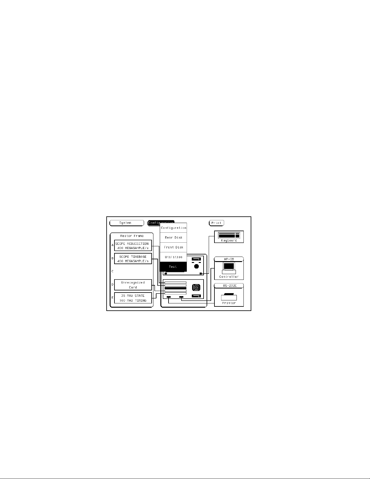
HP 16532A - Service
6-7. Self-Tests
The self-tests for the HP 16532A oscilloscope module will identify the improper operation of major functional areas in the module. T he y are not intended for component level diagnostics.
If there a re multiple oscilloscope modules, the user must select the specific oscilloscope module to be
tested at the ma in te s t sys te m me nu. M ultiple HP 16532A modules that are connected as one unit are recognized as a single unit in the te s t me nu. The external trigger cables connected to the ECL IN an d E CL
OU T do not need to be r emove d i n order t o do t h e se l f-te st for each boa rd. Al l other cable con n ections
mus t be removed.
All s elf-tests can be run without access to the interior of the instrument. If a se lf-test fails , re f er to
section 6-8, " Troubleshooting."
Self-Test Access Procedure:
1. Disconnect all oscilloscope inputs and turn on the power switch.
2. F rom the sta rtup scree n, s h own in figure 6 - 2, touch the Configuration field. Then, touch Test in the
pop-u p m enu.
6-4
Figure 6-2. Startup Screen
Page 69

3. Insta ll the C omposite PV Te s t softwa re disk in the ina ctive disk drive.
4. Touch the box labeled Touch box to Load Test System. Se e figure 6-3.
Note
When the self-test software is loaded, the user operating system is overwritten in
the mainframe system RAM.
HP 16532A - Service
Figure 6-3. L oad Test System Screen
5. From the test system screen in figure 6-4, touch Test System, the n touch 1 GSa/s SCOPE D. (For
the example s h own in figure 6- 4, the oscilloscope module is in slot D. If multiple oscilloscope modules are present, select the one to be tested.)
Figure 6-4. Test System Screen
6-5
Page 70

HP 16532A - Service
Figure 6-5 shows the selection menu for choosing to perform functional tests. The status of the functional
tests is given.
Figure 6-5. Functional Tests Screen
6. Touch the Functional Tests field.
Figure 6- 6 is the ma in s elf-test menu. Self-tests can be e ithe r run individually by touching a specific test
field, or run automatically through all tests one time by touching the All Tests field. Wh e n either All Tests
or individual tests are run, the sta tus will chan ge to eithe r PA SSED or FA ILED. If you do all tests by touch-
ing the All Tests field, skip to step 11. The procedures given in s te ps 7 through 12 us e the A/D Test as an
example of how individual tests are done.
Figure 6-6. Ma in Test Menu
6-6
Page 71

HP 16532A - Service
7. Touch the A/D Test field.
Th e in dividual test run screens, s ee figure 6-7, give the tes t na me , a brief description of the test, number of
test runs, a n d the number of test failures.
Figure 6-7 . A/D Test Run Screen
8. Touch Run, then drag your finger to Single or Repetitive.
During the time a Single run or a Repetitive run is executing, the Run field displays Stop.
9. To stop a R epetitive run, touch Stop. See figure 6-8.
Figure 6-8 . Stop F ield
6-7
Page 72

HP 16532A - Service
10. Touch Done to e xit t he A/D te s t.
11. To exit t he self te sts, touch the following fields in the lettered sequence below:
a. 1GSa/s Scope
b. Test System
c. Configuration
d. Exit Test
12. Touch the box that reads " Touch box to Exit Test Sys tem". See fi gure 6-9.
Figure 6-9. Exit T est System Screen
6-8
Page 73

HP 16532A - Service
Self-Test Descriptions
The following self-tests check the major components of the HP 16532A oscilloscope module as well as a ll
ass ociate d circuitry. W h e n the self- te s ts h ave all be en completed with a "PASS" status, the major data and
control pipelines in the HP 16532A oscilloscope module are functioning properly.
Data Memory Test
Th is test verifi e s the correct operation of the F I SO (fas t- in/s l ow-out) data m e m ory on each board. T est
patterns are writte n into the memory and then re ad and compared with known values .
Timebase Test
Th e pre- trigger an d post-trigger delay modes are f irs t te s te d by programming a predetermined time
interva l in the trigger counters. A t the e n d of the time inte rv als, the arm, trigger, a n d run sta tus bits are
read and compared with known values . The coarse a n d fine inte rpolators are the n checked by reading
the val ue s of the interpolator counters after a simulated acquisition. The counter val ue s are then compared with a known valu e . Finally, the sample clock is checked by programming a sample clock
frequency and then reading the status of the clock to detect when one clock period has elapsed. The
clock period time interval is the n compared with a known val ue .
A/D Test
This test verifies the correct operation of the A/D convertor on each board. A check of the trigger in
Tri gger Imme dia te mode is f irs t ma de . The A/D convertors a re then exercised by se tting the re f erence
voltage and channe l offset such that a simulate d a cquisition obtains data in the e xtre me s and middle of
the quantiza tion ran ge of the A/D convertor. After e ach simulated acquisition, the data is compared with
known values.
D/ A Test
This test verifie s the correct operation of the D/A convertor on ea ch board. Both the offse t a n d trigger
level D/A convertors for each channel are s et to a reference l e v el and then changed. The logic trigger IC
is programmed to detect the changes . The detection of a correct trigger indicates that the D/A convertor
is operating normally.
Trigger Test
This test verifie s the correct operation of the trigger components on each board. First, the logic trigger
memory is checked by writing and then reading known patterns. The logic qualifiers, l ogic trigger output,
and trigger holdoff are checked.
IM B Test
This te s t ve rif ie s the correct operation of the oscilloscope card interface to the intermodule bus.
All Tests
This will automatically execute ea ch tes t, one at a time, until all te s ts a r e done.
6-9
Page 74

HP 16532A - Service
6-8. Troubleshooting
Th e troublesh ooting flow chart given in figure 6-10 will isolate module fa ilures to card leve l only. I t is n ot
intended for component level troubleshooting. If se lf - tes ts indicate a f ailure, begin at the Start of the troubleshooting flow chart. When a s pe cific test fa ils , you will be ins tructed to replace a faulty card or you will
be referred to other flow charts for the isolation of the f aulty card or cable.
The effects of ELECTR OST ATIC D ISCHARG E can damage electronic components. Grounded wriststraps and mats should be used when you perform any
kind of service to this instrument or the cards in it.
Troubleshooting Aids
Th e C a l ibration menu contains the Service Cal mode that can help you troubleshoot the oscilloscope
module. When the problem is found and corrected, run all of the calibration procedures given in
Se ction IV, "Calibration."
If you suspe ct a f ault in the syste m, you can l oad the system defa ult values to see if the NVRAM parameters ha ve possibly been corrupted. T h e procedure for loading the de f a ult v alues is giv en in Se ction IV under the heading "Loading the Default Calibration Factors."
If loading the def ault value s does not fix the problem, you may want to ve rif y that the system clock is
working correctly. T h e procedure to ve rif y the system clock is given below.
If none of thes e aids find the problem, go to the troubleshooting flow chart to find the problem. As s ta te d
above, when the problem is found and corrected, run all of the cali bration procedures given in Section IV
"Ca libration."
6-10
Page 75

HP 16532A - Service
Verifying the System Clock
This procedure is provided as a troubleshooting aid to verify that the 100 MHz System Clock oscillator is
functioning properly. The 100 MHz oscillator is the primary time reference us e d for all of the a cquisition
clock periods. The test limits provided are the test limits for the 100 MHz oscillator only. If the readings
are outside of the test limits, the oscilloscope module will not operate properly.
R e commended
Equipment R e quired C ritical S pecification
Frequency Counter
> 100 MHz, 50 Ω
Model/Part Number
HP 5315A Option 003
Oscilloscope
Cable
Procedure:
1. Connect the BNC cable from the AC CAL OUTPUT connector on the rear panel of the HP 16532A
oscilloscope module to the input of the frequency counter.
2. On the HP 16532A oscilloscope module, set the following parameters, in the order given.
Menu Selection Setting
Channel
Trigger
Calibration
Bandwidth ≥ 100 MHz, Real Time
50 Ω BNC (m to m) 48- in ch
s/Div
Auto-Trig
Mode
Procedure
Signal
HP 54502A
HP 10503A
1 ns
Off
Service Cal
Osc Out
Sample Clk
3. Select RUN-REPETITIVE. Observe the frequency displayed on the frequency counter and verify
that it is 100 MHz ± 0.005%.
4. Di s connect the BNC cable f rom the fre que ncy counter and connect the cable to the input of the
HP 54502A Oscilloscope.
6-11
Page 76

HP 16532A - Service
5. On the HP 54502A Oscilloscope, set the following parameters, in the order given.
Menu Selection Setting
Channel
Probe
V/Div
Offset
Coupling
1.000:1
200 mV
0.0 V
DC
Time bas e
Trigger
6. In the HP 16532A Oscilloscope trigger menu, se l e ct Auto-Trig On. Verify that the 100 MHz System
Cl ock is gate d.
7. Select STOP on both the HP 54502A and HP 16532A oscilloscopes.
8. Disconnect the cable from both oscilloscopes.
s/Div
Acquisition
Mode
Level
Slope
10 ns
Realtime
Edge
− 200 mV
Falling
6-12
Page 77

Troubleshooting Sheet 1
HP 16532A - Service
H
P
1
6
5
3
2
A
T
R
O
U
B
L
E
S
H
O
O
T
I
N
G
Figure 6-10 . Troubleshooting Flowchart
S
H
E
E
T
1
6-13
Page 78

H
P
1
6
5
3
2
A
T
R
O
U
B
L
E
S
H
O
O
T
N
G
HP 16532A - Service
Troubleshooting Sheet 2
I
S
H
E
E
T
2
Figure 6-10 . Troubleshooting Flowchart
6-14
Page 79

Troubleshooting Sheet 3
HP 16532A - Service
H
P
1
6
5
3
2
A
T
R
O
U
B
L
E
S
H
O
O
T
I
N
G
Figure 6-10 . Troubleshooting Flowchart
S
H
E
E
T
3
6-15
Page 80

H
P
1
6
5
3
2
A
T
R
O
U
B
L
E
S
H
O
O
T
N
G
HP 16532A - Service
Troubleshooting Sheet 4
I
S
H
E
E
T
4
Figure 6-10 . Troubleshooting Flowchart
6-16
Page 81

Troubleshooting Sheet 5
Figure 6-10 . Troubleshooting Flowchart
HP 16532A - Service
H
P
1
6
5
3
2
A
T
R
O
U
B
L
E
S
H
O
O
T
I
N
G
6-17
S
H
E
E
T
5
Page 82

HP 16532A - Service
6-9. Oscilloscope Mod ule Removal and Replaceme nt
The effects of ELECTR OST ATIC D ISCHARG E can damage electronic components. U se grounded wrist straps and mats when you are performing any kind of
service on this module.
Wh e n you ne ed to remove a n d replace a module, te s t the module f irs t to determine the faulty part. If
either of the trigger cables are fa ulty, re move the faulty cable and replace it with a ne w one . Refer to paragraph 6-1 0 f or procedures to remove an d replace a faulty cable. If either of the attenua tors a re faulty, remove the f aulty attenu a tor a n d re pla ce it with a new one. Refer to paragra ph 6-11 f or procedures to remove a n d re place a fa ulty attenuator.
Oscilloscope Module Removal Procedure:
Do not install, remove or replace the module in the instrument unless the instrument power is turned off.
1. Turn off the instrume nt power s witch, un plug the power cord, and disconnect any input or output
connections.
2. Starting from the top, loosen the thumb screws on the fille r pane ls and the cards. See fi gure 6 - 1 1.
Figure 6-11 . Endplate Ov erlap - Top Sequence
3. Starting from the top, pull out the cards and the filler panels halfw ay.
4. P ull out the oscilloscope module completely.
6-18
Page 83

HP 16532A - Service
5. If a trigger cable w a s determined to be faulty, re pla ce the faulty trigger cable on the oscilloscope
module (refer to paragraph 6- 1 0). Otherwise, s kip to step 6.
6. If a n attenuator was dete rmine d to be fa ulty, replace the faulty attenuator on the oscilloscope module (ref e r to paragraph 6-11). Otherwise, skip to step 7.
7. If the oscilloscope module was determined to be faulty, re m ove the attenu a tors f r om the oscilloscope module ( r efe r t o paragraph 6-11 ) .
8. A cquire a replacement oscilloscope module and install the attenuators on the replacement oscilloscope module ( r efe r t o paragraph 6-11 ) .
9. Reinstall t he repaire d (or replacement) oscilloscope module in the mainframe (refer to the next procedure "Oscilloscope Module Replacement Procedure").
Oscilloscope Module Replacement Procedure
1. If you ha v e not already done so, pull the installe d boards half w a y out of the card slots (refe r to
steps 1 through 3 of the preceding procedure "Os cilloscope Module Removal").
2. Determine which modules you want to install in the mainf ra me , and the slots where you want them
installed.
3. Starting with the bottom slot, slide e ach module to be installed approximately halfway into the mainframe card slot.
4. F irmly s eat the bottom card into the backplane connector. Keep applying pressure to the center
of the card endplate while tightening the thumb screws finger tight.
5. Repeat step 4 for all cards and filler panels in a bottom-to-top order. See figure 6-1 2 .
F igure 6-1 2 . Endplate Overlap - Bottom Sequence
6. A ny fille r pane ls tha t a re not used should be kept for future use. Fille r pane ls mu st be i nsta l led in
all unuse d card slots for correct air circulation.
6-19
Page 84

HP 16532A - Service
6-10. Trigger Cable Removal and Replacement
The effects of ELECTR OST ATIC D ISCHARG E can damage electronic components. U se grounded wriststraps and mat s when performing any kind of service
to this instrument or the cards in it.
Trigger Cable Removal Procedure:
1. Follow the procedures given in paragraph 6-9 " Os cilloscope Module Removal a nd Replacement" to
remove the HP 16532A Oscilloscope Module to be serviced.
2. Remove the hex nut (H4) a n d the wa sher (H5) from the SMB connector on the cable to be rem ove d.
See figure 6-13.
6-20
Figure 6-1 3. Oscilloscope Module Ex plode d View
Page 85

HP 16532A - Service
3. Pull the straight SM B connector on the cable through the hole in the rea r pan e l.
4. P ull the right-a n gle SMB connector on the cable awa y f rom its mating connector on the board.
5. Install a new cable (refer to the next paragraph).
Trigger Cable Replacement Procedure:
1. Ins ta ll the s tra i ght S M B connector on the cable through the hole in the rear panel. S ee figure 6- 1 3.
2. Attach the wash e r ( H5 ) and the hex nut (H4 ) to the s tra i ght SMB connector on the cable. T i ghten
the hex nut.
3. Conne ct the right-angle SMB connector on the cable to its mating connector on the board.
6-11. Attenuator Removal and Replacement
The effects of ELECTR OST ATIC D ISCHARG E can damage electronic components. U se grounded wriststraps and mat s when performing any kind of service
to this instrument or the cards in it.
Attenuator Removal Procedure:
1. Follow the procedures given in paragraph 6-9 " Os cilloscope Module Removal a nd Replacement" to
remove the HP 16532A Oscilloscope Module to be serviced.
2. Remove the f our he x nuts (H3 ) f rom the BN C connectors on the rear pane l (M P1). See figure 6-13.
3. Remove the two hex nuts (H4) and the two washers (H5 ) from the SMB connectors on the rear
panel.
4. Remove the thre e end plate screws (H6) holding the rear pane l (M P1) and the ground spring (MP2)
to the board asse mbly (A1).
5. P ull the re ar panel (MP1 ) and the ground spring (MP2) from the board assembly (A1). You may
need to loosen the a ttenua tor retainer screws (H7) before removing the ground spring.
6. Remove the two attenuator retainer screws (H7) holding the attenuator assembly (A2 ) to the board
ass e m bly (A 1 ).
7. Gently pull the attenuator as s e m bly (A2) straight up from the board assembly (A 1 ) bein g careful n ot
to damag e the conn ector and the compo nent s beneath the attenua t or assem bl y.
8. Install a new attenuator assembly (refer to the next paragraph "Attenuator Replacement Procedure").
6-21
Page 86

HP 16532A - Service
Attenuator Replacement Procedure:
a. G e ntly push the a tte n ua tor as s e m bly (A 2 ) stra i ght down on the board asse mbly (A 1) being careful
not to damage the connector and the components beneath the attenuator assembly. See figure
6-13.
b. Attach the attenuator ass embly (A2) to the board assembly (A1 ) with the two a tten u a tor reta i n e r
screws (H7).
c. Asse mble the re ar panel (MP1) a n d the ground spring (MP2) to the board assembly (A1 ) a nd attach
them with the thre e end plate screws (H6 ). You may nee d to loosen the attenuator retaine r s crews
(H7) before assembling the ground spring to the board assembly, then tighten the attenuator
screws (H7) when the ass e mbly is finished.
d. Attach the SMB connectors to the rear pane l (MP1) with two hex nuts ( H4 ) and two washers (H5 ).
e. Attach the BNC connectors to the rea r pan el (MP1 ) with four h e x nuts ( H3 ).
Note
Tighten the hex nuts down so that they will not interfere with the installation of the
boar d above th e oscilloscope modu le. One of the f lat surfaces on the outside
edge of the nut should be parallel with the top edge of th e rear panel.
6-22
Page 87

CERTIFICATION
Hewle tt-Packard Company certif ies that this product met its published specifications at the time of shipment from the f actory. Hew lett-Packar d furthe r certif i es that its calibra tion measureme nts are tracea ble to
the Unite d States Na tiona l I nstitute of Stan dards and Technology, to the extent allowed by the Institute’s
calibration facility, and to the calibration facilities of other Interna tional Standards Organiza tion members.
WARRANTY
This H e wl e tt-Packard product is warrante d aga ins t defects in materia l and workmanship for a period of
one year from date of s hipment. D uring the w a rra nty pe riod, Hewle tt-Packard Company will, at its option,
either repair or replace products which prove to be defective.
For warra nty s ervice or repair, this product must be returned to a service facility des i gnated by HP. Buyer
shall prepa y s h i pping charges to HP and HP sha ll pa y s h i pping charges to return the product to Buyer.
However, Buyer shall pay a ll shipping charges, duties, and taxes for products returned to HP from another
country.
HP wa rra nts that its software and firmware designate d by HP f or use with an instrument will e x e cute its programming instructions when properly instal le d on that instrument. HP does not warra nt that the operation
of the instrument or software, or firmware will be uninte rrupted or error free.
LIMITATION OF WARRANTY
Th e foregoing warranty s h a ll not apply to defects resulting from improper or inadequate ma inte na n ce by
Buyer, buyer-s u pplied software or interfa cing, unauthorize d modification or misuse, operation outside the
environmental spe cifications for the product, or improper site preparation or maintenance.
NO OTHER WARRANTY IS EXPRESSED OR IMPLIED. HP SPECIFICALLY DISCLAIMS THE IMPLIED WARRANTIES OF MERCHANTABILITY AND FITNESS FOR A PARTICULAR PURPOSE .
EXCLUSIVE REMEDIES
THE R E MEDIES P ROVIDED HERE IN AR E BUY E R’S SOLE AND EXCLUSIVE REMEDIES. HP SHALL NOT
BE LIABLE FOR ANY DIRECT, INDIRECT, SPECIAL, INCIDENTAL, OR CONSEQUENTIAL DAMAGES,
WHETHER BASED ON CONTRACT, TORT, OR ANY OTHER LEGAL THEORY.
ASSISTANCE
Product maintenance agreements and other customer assista nce a gree me nts are avai la ble f or Hewle ttP acka rd produ ct s.
For any assistance, contact your nearest Hewlett-Packard Sales and Service Office.
CWA388
 Loading...