

Page 1

Artisan Technology Group is your source for quality
new and certied-used/pre-owned equipment
• FAST SHIPPING AND
DELIVERY
• TENS OF THOUSANDS OF
IN-STOCK ITEMS
• EQUIPMENT DEMOS
• HUNDREDS OF
MANUFACTURERS
SUPPORTED
• LEASING/MONTHLY
RENTALS
• ITAR CERTIFIED
SECURE ASSET SOLUTIONS
SERVICE CENTER REPAIRS
Experienced engineers and technicians on staff
at our full-service, in-house repair center
Instra
Remotely inspect equipment before purchasing with
our interactive website at www.instraview.com
Contact us: (888) 88-SOURCE | sales@artisantg.com | www.artisantg.com
SM
REMOTE INSPECTION
View
WE BUY USED EQUIPMENT
Sell your excess, underutilized, and idle used equipment
We also offer credit for buy-backs and trade-ins
www.artisantg.com/WeBuyEquipment
LOOKING FOR MORE INFORMATION?
Visit us on the web at www.artisantg.com for more
information on price quotations, drivers, technical
specications, manuals, and documentation
Page 2
HP 16520A/16521A
PATTERN GENERATION MODULE
Service Manual
Flin-
~e.II
Artisan Technology Group - Quality Instrumentation ... Guaranteed | (888) 88-SOURCE | www.artisantg.com
HEWLETT
PACKARD
Page 3
rlin-
~~
HEWLETT
PACKARD
SERVICE MANUAL
HP
Pattern Generator
16520A 50 MBit/s
Master
Card
AND
HP
16521A 50 MBit/s
Pattern Generator Expansion Card
© COPYRIGHT HEWLETT-PACKARD COMPANY/COLORADO DIVISION 1987
OF
1900 GARDEN
THE GODS ROAD, COLORADO SPRINGS, COLORADO U.S.A.
Manual Part No. 16520·90901
Microfiche Part No. 16520·90801
Artisan Technology Group - Quality Instrumentation ... Guaranteed | (888) 88-SOURCE | www.artisantg.com
ALL
RIGHTS RESERVED
PRINTED: SEPTEMBER 1987
Page 4

CERTIFICATION
Hewlett-Packard Company certifies that this product met its published specifications at the time
shipment from the factory. Hewlett-Packard further certifies that its calibration measurements are
traceable to the
calibration facility, and to the calibration facilities of other International Standards Organization
members.
United States National Bureau of Standards, to the extent allowed
by
the Bureau's
of
WARRANTY
This Hewlett-Packard product
period of one year from date of shipment. During the warranty period, Hewlett-Packard
will, at its option, either repair or replace products which prove to
For warranty service or repair, this product must
Buyer
shall prepay shipping charges to
product to Buyer. However,
HP
returned to
HP
warrants that its software and firmware deSignated by
from another country.
execute its programming instructions when properly
warrant that the operation of the instrument or software, or firmware will
free.
is
warranted against defects in material and workmanship for a
be
defective.
be
returned to a service faCility deSignated by HP.
HP
and
HP
shall pay shipping charges to return the
Buyer shall pay
all
shipping charges, duties, and taxes for products
HP
for
use
with
an
instrument will
installed on that instrument.
be
uninterrupted or error
HP
Company
does not
LIMITATION
OF
WARRANTY
The foregoing warranty shall not apply to defects resulting from improper or inadequate
maintenance by Buyer, buyer-supplied software or interfacing, unauthorized modification or
misuse, operation outside the environmental specifications for the product, or improper site
preparation or maintenance.
NO OTHER WARRANTY
IMPLIED WARRANTIES
THE REMEDIES PROVIDED HEREIN ARE BUYER'S SOLE AND EXCLUSIVE REMEDIES.
SHALL NOT BE LIABLE
CONSEQUENTIAL DAMAGES, WHETHER BASED
THEORY.
IS
EXPRESSED
OF
MERCHANTABILITY AND FITNESS FOR A PARTICULAR PURPOSE.
EXCLUSIVE REMEDIES
FOR
ANY
OR
IMPLIED. HP SPECIFICALLY DISCLAIMS THE
DIRECT, INDIRECT, SPECIAL, INCIDENTAL,
ON
CONTRACT, TORT,
OR
ANY
OTHER LEGAL
HP
OR
ASSISTANCE
Product maintenance agreements and other customer assistance agreements are available for
Hewlett-Packard products.
For any
provided at the back of this manual.
aSSistance, contact your nearest Hewlett-Packard Sales and Service Office. Addresses are
Artisan Technology Group - Quality Instrumentation ... Guaranteed | (888) 88-SOURCE | www.artisantg.com
CWA584
Page 5
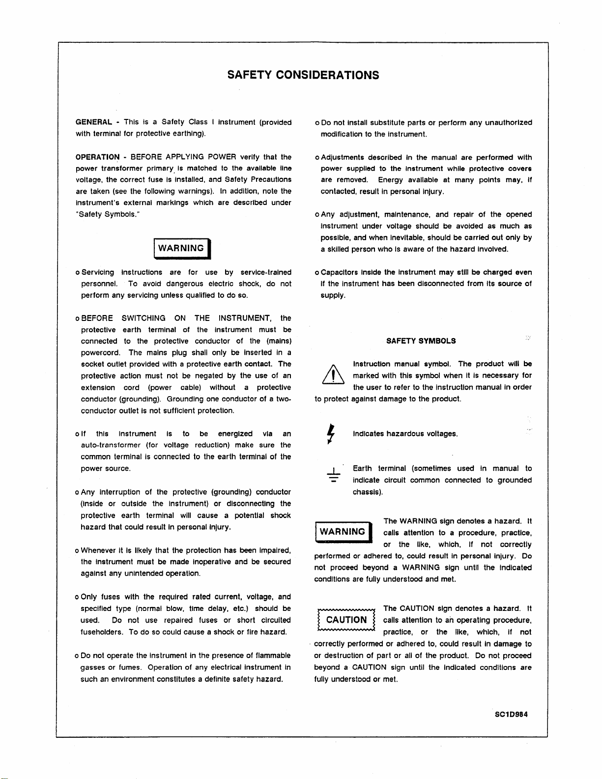
SAFETY CONSIDERATIONS
GENERAL - This
with terminal for protective earthing).
OPERATIO~
power transformer primary.
voltage, the correct fuse
are taken
Instrument's external markings which are described under
"Safety Symbols."
(see
Is
a Safety Class I Instrument (provided
- BEFORE APPLYING POWER verify that the
Is
matched to the available line
Is
Installed, and Safety Precautions
the following warnings). In addition, note the
I WARNING I
o Servicing Instructions are for use by service-trained
personnel. To avoid dangerous electric shock, do
perform any servicing unless qualified to do
o BEFORE SWITCHING
protective earth terminal of the Instrument must
connected to the protective conductor
powercord. The mains
socket outlet provided with a protective earth contact. The
protective action must not be negated by the use of
extension cord (power cable) without a protective
conductor (grounding). Grounding one conductor of a twoconductor outlet
Is
ON
THE INSTRUMENT, the
plug shall only
not sufficient protection.
so.
of
be
Inserted
the (mains)
not
be
In
an
Do
not Install substitute parts or perform any unauthorized
o
modification to the Instrument.
o Adjustments described
power
supplied to the Instrument while protective covers
are removed. Energy available at many
contacted, result In personal Injury.
o Any adjustment, maintenance, and repair
Instrument under voltage should be avoided
possible, and when
a skilled person who
CapaCitors Inside the Instrument may stili be charged even
o
If the Instrument has been disconnected from Its source
supply.
a
Instruction manual symbol. The product will
In
Inevitable, should
Is
aware of the hazard Involved.
SAFETY SYMBOLS
ill marked with this symbol when It
the user to refer to the Instruction manual
to protect against damage to the product.
the manual are performed with
pOints may, If
of
the opened
as
much as
be
carried
out
only
by
of
be
Is
necessary for
In order
If this Instrument
o
auto-transformer (for voltage reduction) make sure the
common terminal is connected to the earth terminal of the
power source.
o Any Interruption of the protective (grounding) conductor
(Inside or outside the Instrument)
protective earth terminal will cause a potential shock
hazard that could
It
Is
o Whenever
the Instrument must
against any unintended operation.
Only fuses with the required rated current, voltage, and
o
specified type (normal blow, time delay, etc.) should be
used. Do not use repaired fuses or short circuited
fuseholders. To do so could cause a shock or fire hazard.
o Do not operate the Instrument in the presence of flammable
gasses or fumes. Operation of any electrical Instrument
such
an
likely that the protection has been Impaired,
environment constitutes a definite safety hazard.
Is
to
be
energized
or
disconnecting the
result In personal Injury.
be
made Inoperative and be secured
via
an
~
Indicates hazardous voltages.
-L
Earth terminal (sometimes used In manual to
indicate circuit common connected
chassis).
The WARNING sign denotes a hazard. It
attention to a procedure, practice,
I WARNING I
performed or adhered to, could result
not proceed beyond a
conditions are
':::~:::::~:~~;:~!
~i
I
. correctly performed or adhered to, could result
or destruction
In
beyond a
fully understood
CAUTION sign until the Indicated conditions are
calls
or
the like, which, If
WARNING sign until the Indicated
fully understood and met.
The CAUTION sign denotes a hazard. It
calls attention to an operating procedure,
practice, or the like, which,
of
part or
all
of the product. Do not proceed
or
met.
to
grounded
not
correctly
In personal Injury. Do
If
not
In
damage to
S010984
Artisan Technology Group - Quality Instrumentation ... Guaranteed | (888) 88-SOURCE | www.artisantg.com
Page 6
HP
16520/21 A-Table of Contents
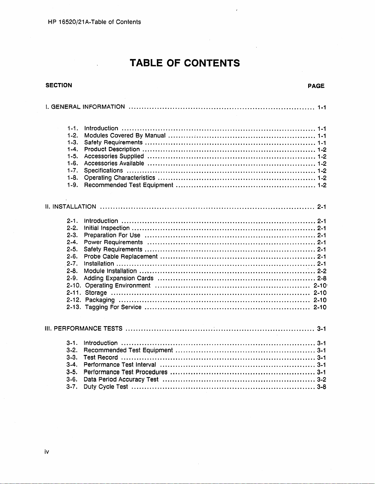
TABLE OF CONTENTS
SECTION
I.
GENERAL INFORMATION
1-1. Introduction
1-2. Modules Covered By Manual
1-3. Safety Requirements
1-4. Product Description
1-5. Accessories Supplied
1-6. Accessories
1-7. Specifications
1-8. Operating Characteristics
1-9. Recommended Test Equipment
II.
INSTALLATION
2-1. Introduction
2-2. Initial Inspection
2-3. Preparation
2-4. Power Requirements
2-5. Safety Requirements
2-6. Probe Cable Replacement
...................................................................................
2-7. Installation
2-8. Module Installation
2-9. Adding Expansion Cards
2-10. Operating Environment
2-11. Storage
2-12. Packaging
2-13. Tagging
For
........................................................................
...........................................................................
.......... ~ ..............................................
..................................................................
...................................................................
.................................................................
Available
.........................................................................
...........................................................................
For
.............................................................................
.............................................................................
..........................................................................
Service
.................................................................
.............................................................
......................................................
.......................................................................
Use
..................................................................
.................................................................
..................................................................
............................................................
....•.............•...................................................
.............................................................
............................................................
................................................................
PAGE
1-1
1-1
1-1
1-1
1-2
1-2
1-2
1-2
1-2
1-2
2-1
2-1
2-1
2-1
2-1
2-1
2-1
2-1
2-2
2-8
2-10'
2-10
2-10
2-10
III. PERFORMANCE
3-1. Introduction
3-2. Recommended Test Equipment
3-3. Test Record
3-4. Performance Test Interval
3-5. Performance Test Procedures
3-6.
Data
3-7. Duty Cycle Test
iv
Artisan Technology Group - Quality Instrumentation ... Guaranteed | (888) 88-SOURCE | www.artisantg.com
TESTS
Period Accuracy Test
..................................
...........................................................................
...........................................................................
.......................................................................
:
......................................
......................................................
............................................................
""""",.,""""""""""""",.".,.,
.......................................
,
...................
.•
,"',.,'
3-1
3-1
3-1
3-1
3-1
3-1
3-2
3-8
Page 7
HP
16520/21 A-Table of Contents
SECTION
IV.
ADJUSTMENTS
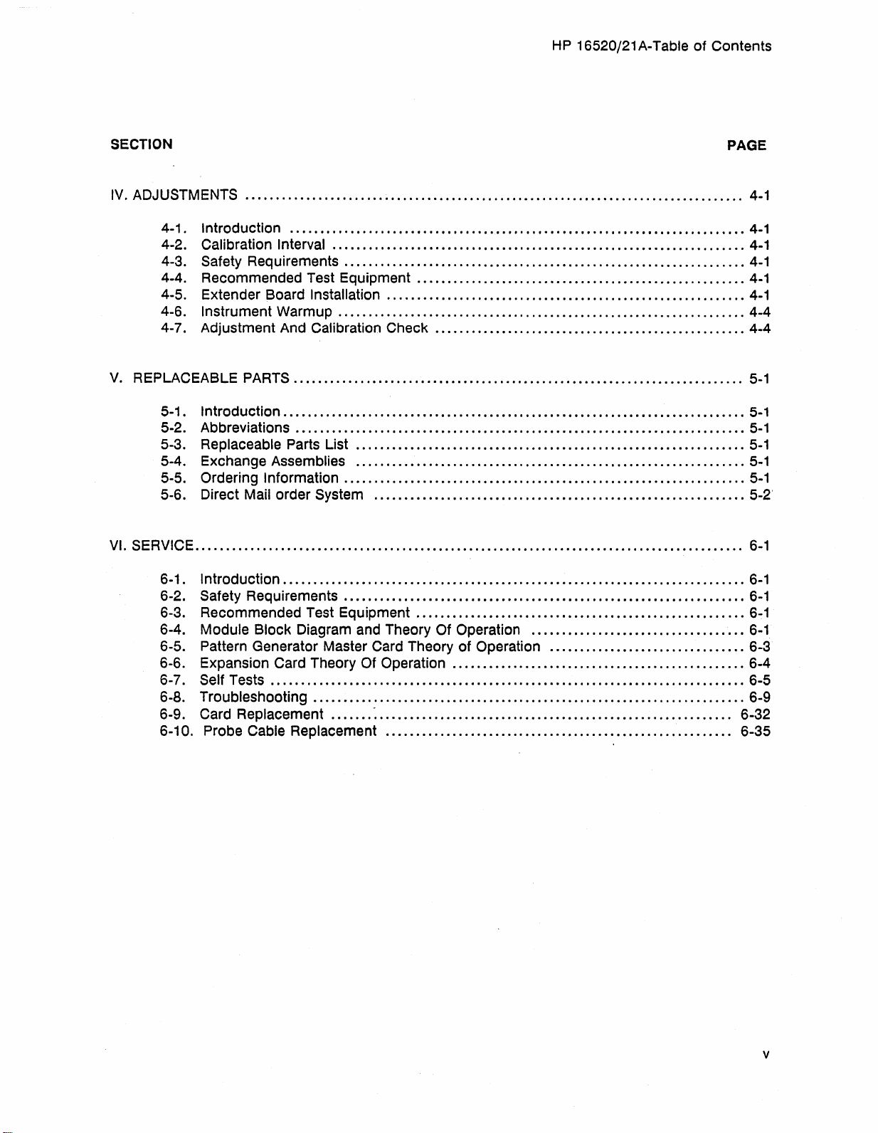
4-1. Introduction
4-2. Calibration Interval
4-3. Safety Requirements
4-4. Recommended Test Equipment
4-5. Extender Board Installation
4-6. Instrument Warmup
4-7. Adjustment And
V.
REPLACEABLE
5-1. Introduction
5-2. Abbreviations
5-3. Replaceable Parts List
5-4. Exchange Assemblies
5-5. Ordering Information
5-6. Direct Mail order System
VI.
SERViCE
..................................................................................
...........................................................................
....................................................................
..................................................................
......................................................
...........................................................
...................................................................
PARTS
Calibration Check
..........................................................................
...................................................
............................................................................
..........................................................................
................................................................
................................................................
..................................................................
.............................................................
..........................................................................................
PAGE
4-1
4-1
4-1
4-1
4-1
4-1
4-4
4-4
5-1
5-1
5-1
5-1
5-1
5-1
5-2'
6-1
6-1. Introduction
6-2. Safety Requirements
6-3. Recommended Test Equipment
6-4. Module Block Diagram and Theory Of Operation
............................................................................
...........................•......................................
......................................................
...................................
6-5. Pattern Generator Master Card Theory of Operation
6-6. Expansion
6-7.
Self Tests
Card Theory Of Operation
..............................................................................
6-8. Troubleshooting
6-9.
Card Replacement
6-10. Probe
Cable Replacement
.......................................................................
....... -...........................................................
.........................................................
................................................
................................
6-1
6-1
6~1
6-1
6-3
6-4
6-5
6-9
6-32
6-35
Artisan Technology Group - Quality Instrumentation ... Guaranteed | (888) 88-SOURCE | www.artisantg.com
v
Page 8
HP
16520/21 A-Table of Contents
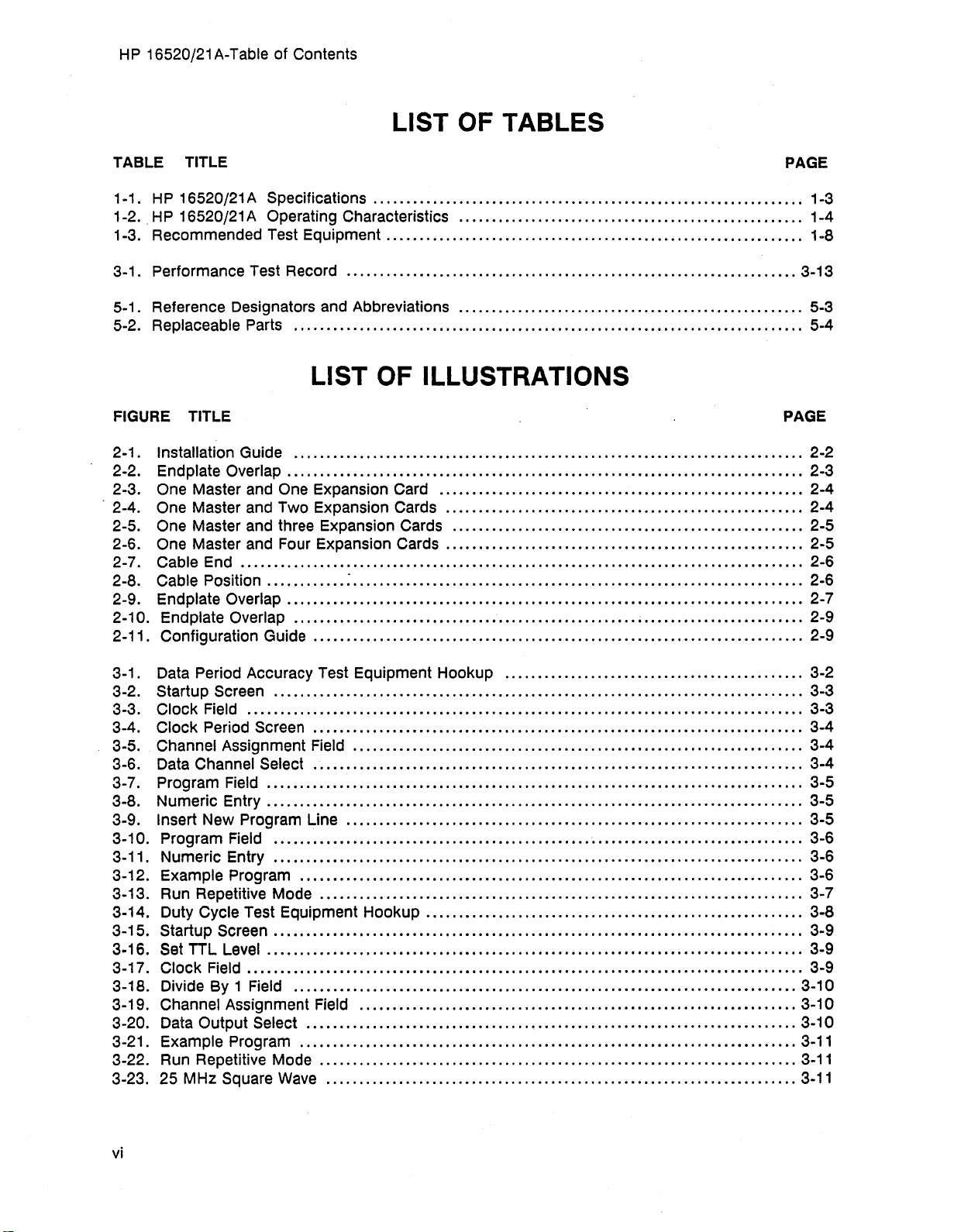
LIST OF TABLES
TABLE TITLE
1-1.
HP
16520/21 A Specifications
"HP
1-2.
16520/21 A Operating Characteristics
1-3. Recommended Test Equipment
3-1. Performance Test Record
.................................................................
........................................................
.0
•••••••••
0
••••••••••••••••••••••••••••••••••••••••••••••••••••••••
5-1. Reference Designators and Abbreviations
5-2. Replaceable Parts
.............................................................................
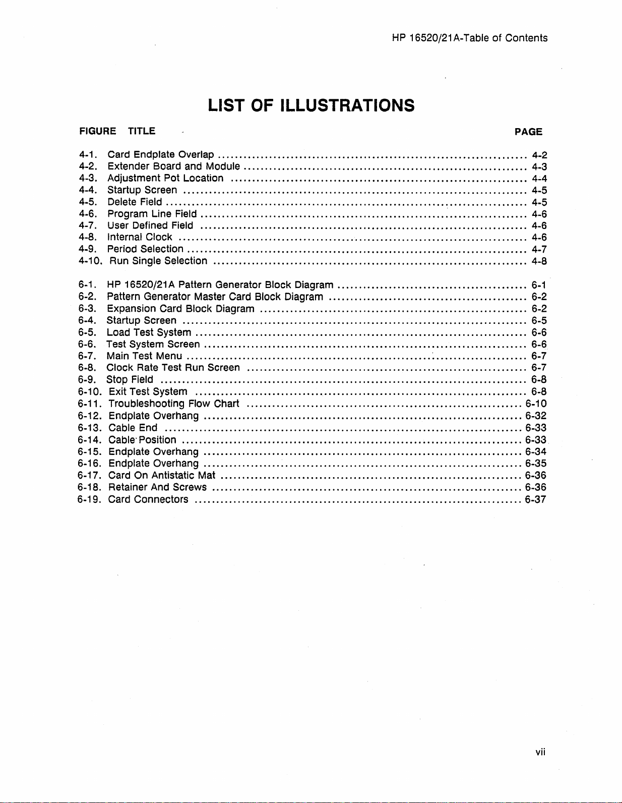
LIST OF ILLUSTRATIONS
FIGURE
2-1. Installation Guide
2-2. Endplate
2-3.
2-4.
2-5. One Master and three Expansion Cards
2-6. One Master and Four Expansion Cards
2-7.
2-8.
2-9. Endplate
2-10. Endplate
2-11. Configuration Guide
TITLE
Overlap
..............
................................................•......................•......
0
••• 0 •••••••••••••••••••••••••••••••••••
One Master and One Expansion Card
One Master and Two Expansion Cards
Cable End
Cable Position
..............................................................................
............ : ....................................................................
Overlap
Overlap
..............................................................................
....................................................
........................................................
....................................................
....................................................
0
•••••••••••••••
................................................
....
0
.................................................
.....................................................
......................................................
~
.................
0 • • • • • • • • • • • • • • •
00000
0
••••••
0
......
0 0 • • •
0
••••••
PAGE
1-3
1-4
••
1-8
3-13
5-3
5-4
PAGE
2-2
2-3
2-4
2-4
2-5
2-5
••
2-6
2-6
2-7
2-9
••
2-9
3-1
. Data Period Accuracy Test Equipment Hookup
3-2. Startup Screen
3-3.
Clock Field
Clock Period Screen
3-4.
3-5.
Channel Assignment Field
3-6. Data
Channel Select
3-7. Program Field
3-8. Numeric Entry
3-9.
Insert New Program Line
3-10. Program
3-11. Numeric Entry
3-12. Example Program
3-13. Run Repetitive Mode
3-14. Duty
3-15.
Cycle Test Equipment Hookup
Startup Screen
3·16. Set TTL Level
3-17.
Clock Field
3-18. Divide By 1 Field
3-19.
3-20. Data
Channel Assignment Field
Output Select
3-21. Example Program
3-22. Run Repetitive Mode
3-23. 25 MHz Square
................................................................................
.....................
0
•••• 0 •••••••••••••••••••••••••••••••••••••••
..........................................................................
........
0........................................................... 3-4
................................................
..............................
....
0
••••••••••••••••••••••••••••••••••••
..................
Field
..
0 0
•••••
0
•••••••••••••••••••
...
0
•••••
0
•••••••••••••••••••
.........................
.......................................................
.........................................................
...
0
••••••••••••••••••••••••••••••••••••••••••••••••••••••••••••••••••
..............................•................................
.................................•................
.....................................
..........
0
•••••••••••••••••••••••••••••••••••••••••••••••••••••••
.................................................................
.........................
......................
Wave
.......................................................................
.... . ..
0
•••••••••••••••••••••••••••
o
•••••••••••••••••••
0
•••••••••••••
0 0
•••••••••••••••••••••••••••••••
0
•••••••••••••••••••••••••••••••••••••••••
0
•••••••••••••••••••••••••••••••••••••••••••••••••
0
•••••••••••••••••••••••••••••••••••••••••••••••••
..
..
0
••••••••••••••••••
0
•••• " •••••••••••••••••••••••
0
••••••••••••••••••••••••••••••••••••••
..
0
••••••••••••••••••••••
..
.. .. ..
0
••••••••••••••••••••••••••••••
0
••••••••••••••••••
..
..
..
.. . ..
0 • • • • • • • • • • • • • • •
0
•••••••••••••••
0
•••••••••••
0
••••••
0
•••••••••••••••••
0
•••••••••••••••••
..
..
.. .. ..
00
0 • 0 • • • •
0.
• • • • • • •
0
0 0 • • • • • •
0 • • • • • • • •
o
••••••••
0 • • • •
0 • • • •
•••••••
••••••••
...
••
••
••
••
••
••
••
3-2
3-3
3-3
3-4
3-4
3-5
3-5
3-5
3-6
3-6
3-6
3-7
3-8
3-9
3-9
3-9
3-10
3-10
3-10
3-11
3-11
3-11
vi
Artisan Technology Group - Quality Instrumentation ... Guaranteed | (888) 88-SOURCE | www.artisantg.com
Page 9
HP
16520/21 A-Table
of
Contents
LIST
FIGURE TITLE
4-1
. Card Endplate Overlap
4-2. Extender Board and Module
4-3. Adjustment
4-4. startup Screen
4-5.
Delete Field
Program Line Field
4-6.
4-7. User Defined Field
4-8.
Internal Clock
Period Selection
4-9.
4-10, Run Single Selection
HP
6-1.
6-2. Pattern Generator Master Card Block Diagram
6-3. Expansion Card
6-4. Startup
6-5. Load Test
6-6. Test
6-7. Main Test Menu
6-8.
6-9.
6-10. Exit Test System
6-11. Troubleshooting Flow Chart
6-12. Endplate Overhang
6-13.
6-14.
6-15. Endplate Overhang
6-16. Endplate Overhang
6-17. Card
6-18. Retainer And
6-19. Card Connectors
16520/21 A Pattern Generator Block Diagram
System Screen
Clock Rate Test Run Screen
Stop Field
Cable End
Cable"
On Antistatic Mat
Pot Location
................................................................................
....................................................................................
.................................................................................
...............................................................................
Block Diagram
Screen
Position
................................................................................
System
.........................................................
.....................................................................................
...................................................................................
...............................................................................
Screws
........................................................................
............................................................................
............................................................................
.........................................................................
.............................................................................
...........................................................................
...................•.........................................................
..........................................................................
..........................................................................
..........................................................................
......................................................................
........................................................................
............................................................................
OF
ILLUSTRATIONS
..................................................................
................................
..............................................................
.................................................................
................................................................
. . . . . . . . . . . . . . . . . . . . . . . . . . . . . . . . . . .
............................................
..............................................
~
.....................
PAGE
4-2
4-3
..
4.;.4
4-5
4-5
4-6
4-6
4-6
4-7
4-8
6-1
6-2
6-2
6-5
6-6
6-6
6-7
6-7
6-8
6-8
6-10
6-32
6-33
6-33,
6-34
6-35
6-36
6-36
6-37
Artisan Technology Group - Quality Instrumentation ... Guaranteed | (888) 88-SOURCE | www.artisantg.com
vii
Page 10

GENERAL INFORMATION
TABLE
OF
CONTENTS
1-1. Introduction
1-2. Modules Covered By Manual
1-3. Safety Requirements
1-4. Product Description
1-5. Accessories Supplied
1-6. Accessories Available
1-7. Specifications
1-8. Operating Characteristics
1-9. Recommended Test Equipment
............................................................................
..........................................................
...................................................................
....................................................................
..................................................................
..................................................................
..........................................................................
........ ; .....................................................
.......................................................
1-1
1-1
1-1
1-2
1-2
1-2
1-2 .
1-2
1-2
Artisan Technology Group - Quality Instrumentation ... Guaranteed | (888) 88-SOURCE | www.artisantg.com
Page 11
HP
16520/21 A - General Information
SECTION I
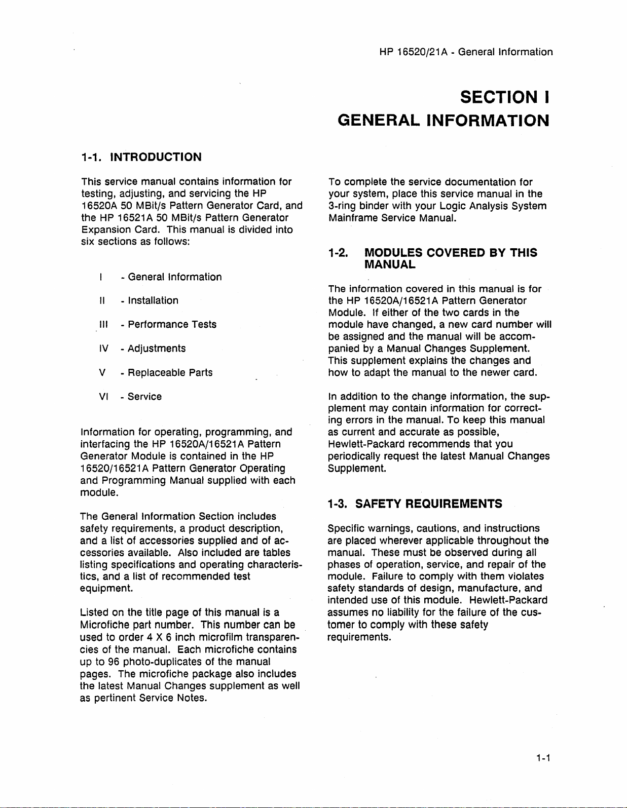
1-1. INTRODUCTION
This service manual contains information for
testing, adjusting, and servicing the
16520A
the
Expansion Card. This manual
six sections
Information
interfacing the
Generator Module
16520/16521 A Pattern Generator Operating
and Programming Manual
module.
The General
safety requirements, a product description,
and a
cessories available. Also included
listing specifications and operating characteristics, and a list of recommended test
equipment.
Listed on the title page of this manual
Microfiche part number. This number can
used to order 4 X 6 inch microfilm transparencies of the manual. Each microfiche contains
up to
pages. The microfiche package also includes
the latest Manual Changes supplement
as
50
MBit/s Pattern Generator Card,
HP
16521 A 50
as
- General Information
II
- Installation
III
- Performance Tests
IV
- Adjustments
V - Replaceable Parts
VI
- Service
for operating, programming,
list of accessories supplied
96
photo-duplicates of the manual
pertinent Service Notes.
MBit/s Pattern Generator
follows:
HP
16520A/16521 A Pattern
is
contained
supplied with each
Information Section includes
HP
is
divided into
in
the
HP
and
of ac-
are
tables
is
as
and
and
a
be
well
GENERAL
To complete the service documentation for
your system, place this service manual in the
3-ring binder with your Logic Analysis
Mainframe Service Manual.
INFORMATION
System
1-2. MODULES COVERED BY THIS
MANUAL
The
information covered
the
HP
16520A/16521 A Pattern Generator
Module.
module
be
panied
This supplement explains the changes and
how to adapt the manual to the newer card.
In
addition to the change information, the supplement may contain information for correcting errors
as
current
Hewlett-Packard recommends that you
periodically request the latest Manual Changes
Supplement.
If either of the two cards in the
have
changed, a new card number will
assigned and the manual will
by
a Manual Changes Supplement.
in
the manual. To keep this manual
and
accurate
in
this manual
as
possible,
be
is
accom-
for
1-3. SAFETY REQUIREMENTS
Specific warnings, cautions, and instructions
are
placed wherever applicable throughout the
manual. These must
phases
module. Failure to comply with them violates
safety standards of design, manufacture, and
intended use of this module. Hewlett-Packard
assumes no
tomer to comply with these safety
requirements.
of
operation, service, and repair of the
liability for the failure of the cus-
be
observed during all
Artisan Technology Group - Quality Instrumentation ... Guaranteed | (888) 88-SOURCE | www.artisantg.com
1-1
Page 12
HP 16520/21 A - General Information
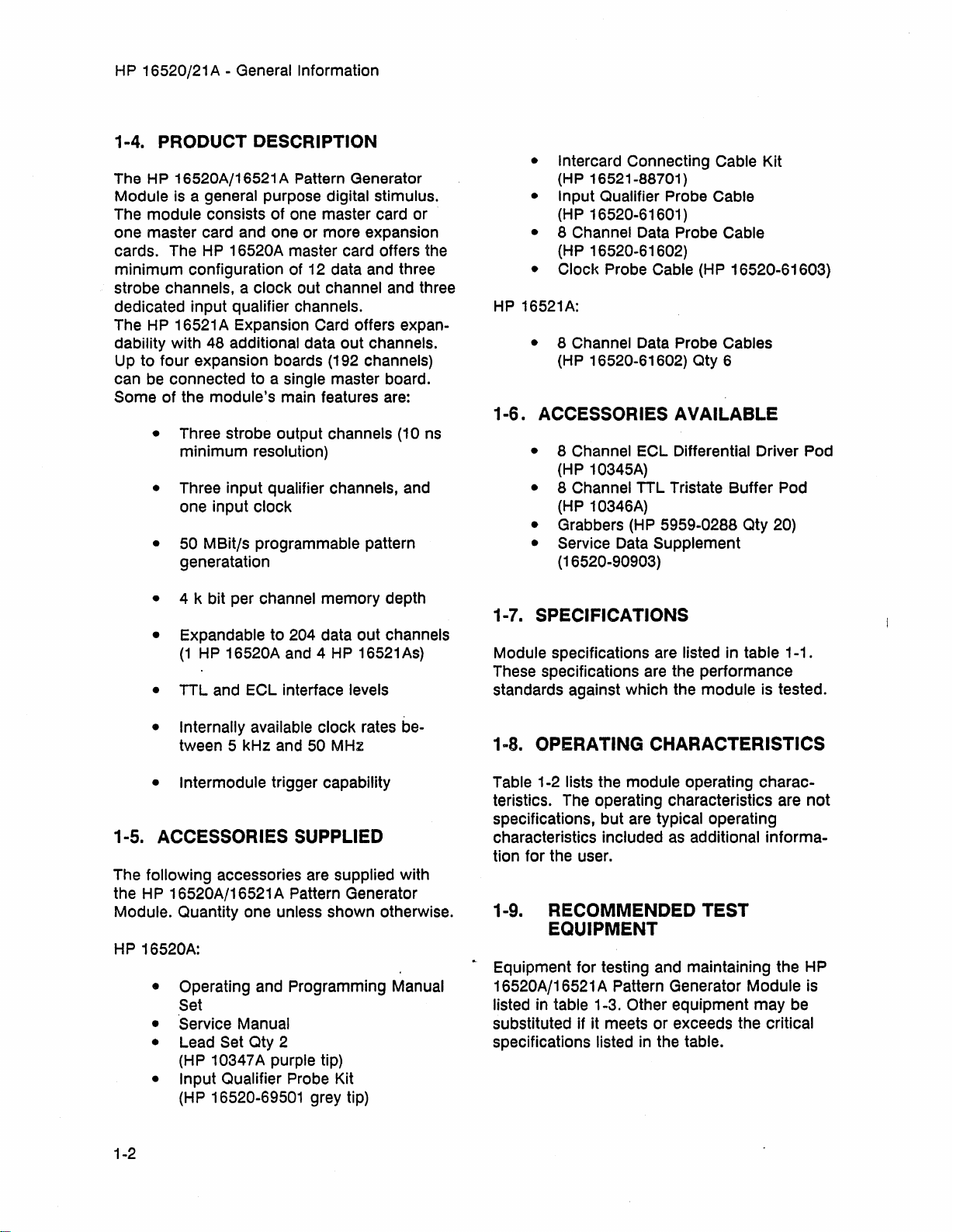
1-4. PRODUCT DESCRIPTION
The HP 16520A/16521 A Pattern Generator
Module is a general purpose digital stimulus.
The module consists
one master card and one or more expansion
cards. The HP
minimum
strobe channels, a clock out channel and three
dedicated input qualifier channels.
The HP 16521 A Expansion
dability with 48 additional data out channels.
Up to four expansion boards (192 channels)
can be connected to a single master board.
Some of the module's main features are:
configuration of 12 data and three
• Three strobe output channels (10 ns
minimum
• Three input qualifier channels, and
one input clock
• 50 MBit/s programmable pattern
generatation
of
one master card or
16520A master card offers the
Card offers expan-
resolution)
• Intercard Connecting Cable Kit
(HP 16521-88701)
• Input Qualifier Probe Cable
(HP
16520-61601)
•
8 Channel Data Probe Cable
16520-61602)
(HP
•
Clock Probe Cable (HP 16520-61603)
HP
16521A:
• 8 Channel Data Probe Cables
(HP
16520-61602) Qty 6
1-6. ACCESSORIES AVAILABLE
• 8 Channel
10345A)
(HP
• 8 Channel
(HP
10346A)
• Grabbers
• Service
(16520-90903)
ECl
Differential Driver Pod
TTL
Tristate Buffer Pod
(HP
5959-0288 Qty 20)
Data Supplement
• 4 k bit per channel memory depth
• Expandable to 204 data out channels
(1
HP 16520A and 4
•
TTL
and
ECl
interface levels
• Internally available clock rates between 5 kHz and 50 MHz
• Intermodule
trigger capability
HP
16521
As)
1-5. ACCESSORIES SUPPLIED
The following accessories are supplied with
the H P 16520A/16521 A Pattern Generator
Module. Quantity one unless shown otherwise.
HP
16520A:
• Operating and Programming Manual
Set
'Service Manual
•
•
lead
Set Qty 2
10347A purple tip)
(HP
• Input Qualifier Probe Kit
16520-69501 grey tip)
(HP
1-7. SPECIFICATIONS
Module specifications are listed in table 1-1.
These specifications are the performance
standards against which the module is tested.
1
..
8.
OPERATING CHARACTERISTICS
Table 1-2 lists the module operating characteristics. The operating characteristics are
specifications, but are typical operating
characteristics included
tion for the user.
as
additional
not
informa-
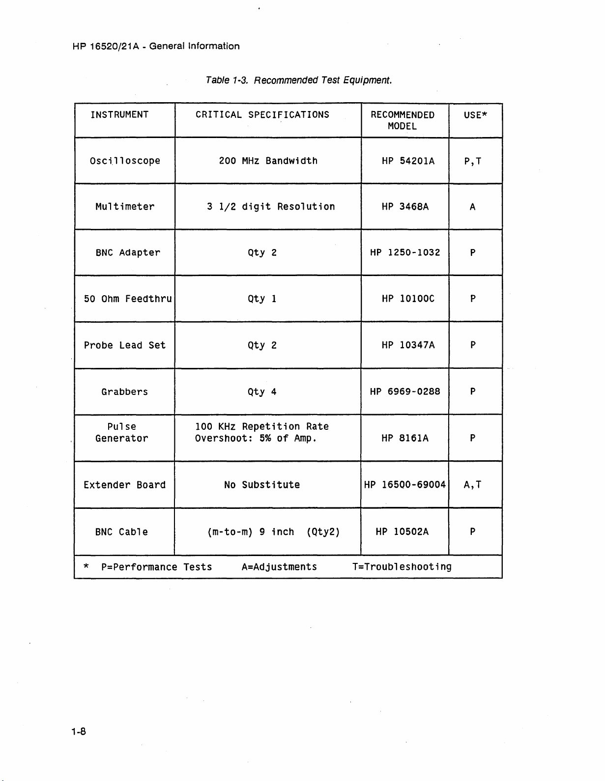
1-9. RECOMMENDED TEST
EQUIPMENT
. Equipment for testing and maintaining the HP
16520A/16521 A Pattern Generator Module is
listed in table 1-3.
substituted if it meets or exceeds the critical
specifications listed in the table.
Other equipment
may
be
1-2
Artisan Technology Group - Quality Instrumentation ... Guaranteed | (888) 88-SOURCE | www.artisantg.com
Page 13

Table 1-1. HP 16520/21 A SpecifIcations.
HP 16520A/21A SPECIFICATIONS
CLOCK SOURCES (HP 16520A ONLY)
INTERNAL CLOCK
HP
16520/21 A - General Information
Clock Period: Programmable from 20 ns to 200
Data Period Accuracy:
EXTERNAL
CLOCK (provided by user)
±
2%
(of period) ± 1 ns
Input Clock Period:
1 Hz to
50 MHz (20 ns min period)
frequency divide (/1, /5, or /10) provided.
Duty cycle:
minimum
high time, 10 ns
10 ns
STROBES (HP 16520A ONLY)
Number
Bits/Channel:
Maximum Bit Rate: 20 MBit/s (50 ns Period)
Edge Placement:
of
Strobes: 3
4095
(Eel
or TTL)
~
10M
Bits/s: tenths of period
> 10 MBits/s to 20 MBits/s: fifths of Period
(DELAY + WIDTH ~ PERIOD)
J1.s
in a 1-2-5 sequence.
Eel
minimum
low time
or TTL, internal
Minimum
Minimum
period
delay is
width is 1/10 (1/5) of data period,
0/10
(0/5),
maximum
delay
maximum
is
9/10 (4/5) data period.
width is the data
(values in parentheses apply to 20 MBits/s timebase setting).
If strobes are desired while operating with external clock, the data rate
will be divided to
Artisan Technology Group - Quality Instrumentation ... Guaranteed | (888) 88-SOURCE | www.artisantg.com
1/5
or 1/10 the external
clock
rate.
1-3
Page 14
HP
16520/21 A - General Information
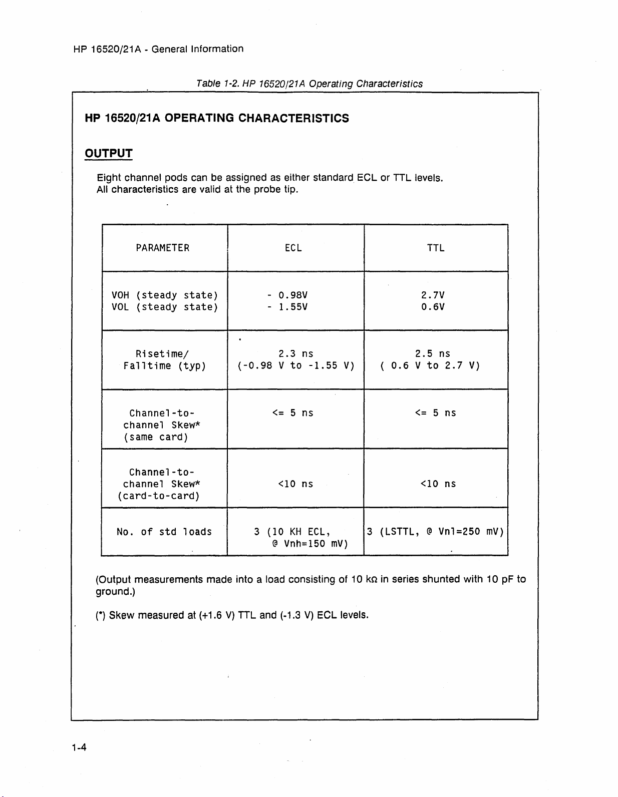
Table
1-2.
HP 16520/21 A Operating Characteristics
HP 16520/21A OPERATING CHARACTERISTICS
OUTPUT
Eight channel pods can
All characteristics
are
valid at the probe tip.
PARAMETER
VOH
VOL
(steady
(steady
state)
state)
Risetime/
Falltime
(typ)
Channel-to-
channel
(same
Skew*
card)
be
assigned
I
as
either standard
Eel
or TTL levels.
ECl
- 0.98V
- 1.55V 0.6V
2.3 ns
V
to
5 ns
-1.55
V)
(
(-0.98
<=
0.6
TTL
2.7V
2.5
V
to
<=
ns
2.7
5 ns
V)
Channel-to-
<10
channel
Skew*
ns
(card-to-card)
of
std
No.
(Output measurements made into a load consisting of 10 kn
ground.)
(*)
Skew measured at (+1.6
1-4
loads
3
(10
V)
TTL and (-1.3
KH
@
Vnh=IS0
ECl,
V)
Eel
mY)
levels.
<10
ns
3 (lSTTl, @ Vnl=2S0
in
series shunted with 10 pF to
mY)
Artisan Technology Group - Quality Instrumentation ... Guaranteed | (888) 88-SOURCE | www.artisantg.com
Page 15
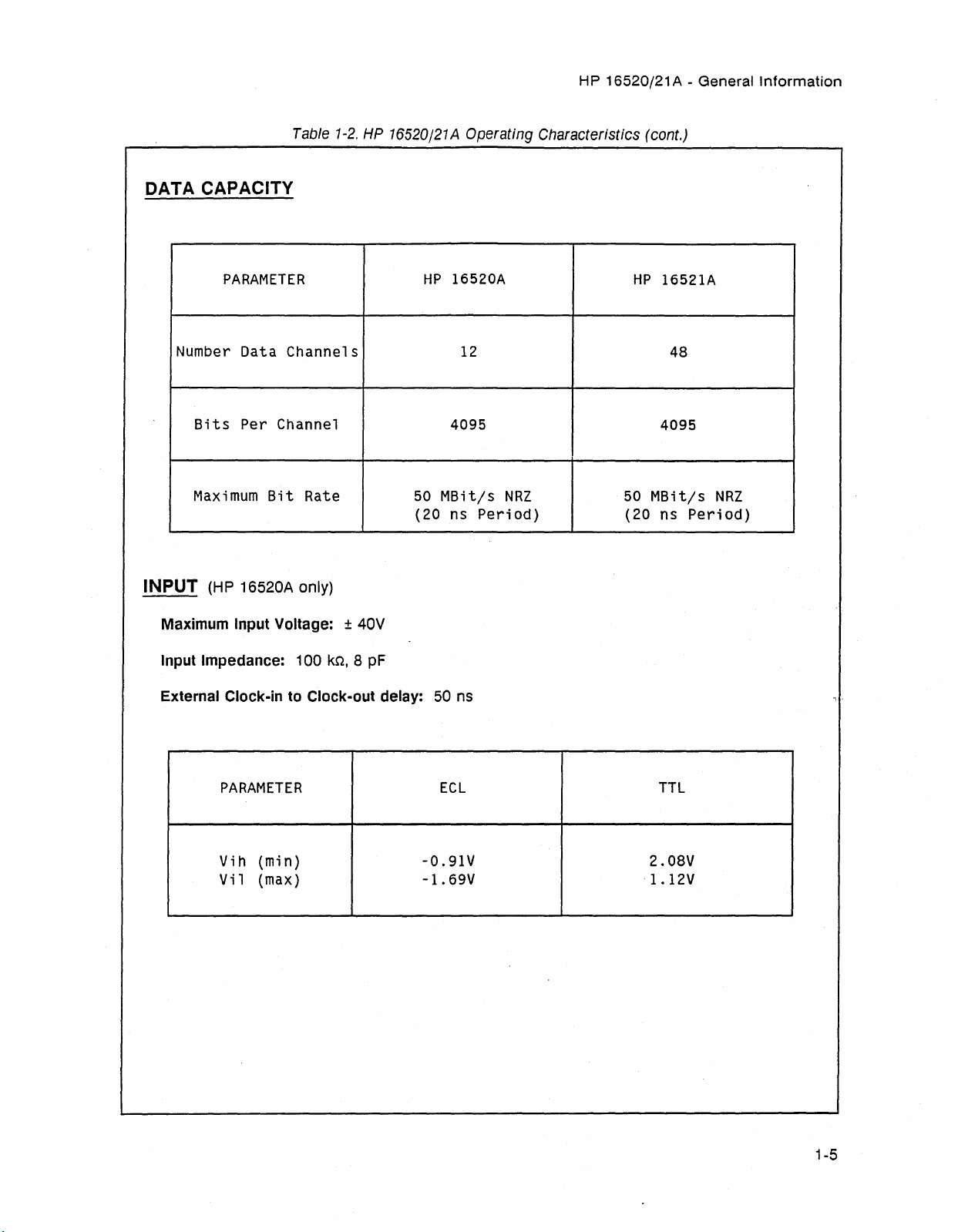
DATA CAPACITY
PARAMETER
Table
1-2.
HP
16520/21
HP
HP 16520/21 A - General
A Operating Characteristics (cont.)
16520A
HP
16521A
Information
Number
Bits
Maximum
Data Channels
Per Channel
Bit
Rate
50
(20 ns
INPUT
Maximum Input Voltage: ± 40V
Input Impedance: 100
External Clock-in to Clock-out delay: 50 ns
(HP
16520A only)
kn,
8
pF
PARAMETER
12
4095
MBit/s
Period)
ECl
NRZ
4095
50
MBit/s
(20 ns
TTL
48
NRZ
Period)
Vih
(min)
Vil
(max)
Artisan Technology Group - Quality Instrumentation ... Guaranteed | (888) 88-SOURCE | www.artisantg.com
-O.91V
-1.
69V
2.08V
1.12V
1-5
Page 16
HP
16520/21 A - General Information
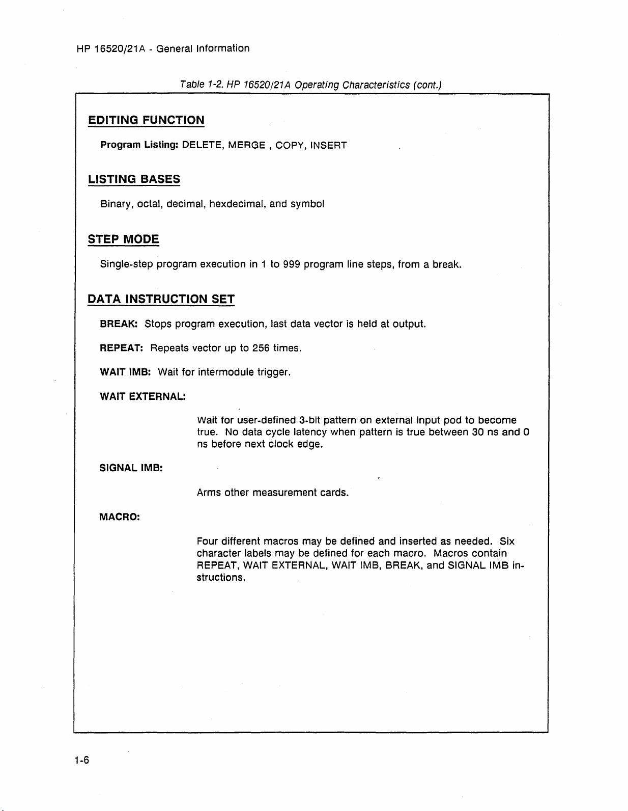
Table
1-2.
HP 16520/21 A Operating Characteristics (cont.)
EDITING FUNCTION
Program Listing: DELETE, MERGE, COPY, INSERT
LISTING
Binary, octal, decimal, hexdecimal, and symbol
BASES
STEP MODE
Single-step program execution
in
1 to 999 program line steps, from a break.
DATA INSTRUCTION SET
BREAK:
REPEAT: Repeats vector up to 256 times.
WAIT
WAIT EXTERNAL:
SIGNAL
Stops program execution, last data vector
1MB:
Wait for intermodule trigger.
Wait for user-defined 3-bit pattern on external input pod to become
true.
No
data cycle latency when pattern
ns
before next clock edge.
1MB:
is
held at output.
is
true between 30 ns and 0
1-6
MACRO:
Arms other measurement cards.
be
Four different macros may
character labels may
REPEAT, WAIT EXTERNAL,
structions.
be
defined and inserted
defined for each macro. Macros contain
WAIT
1MB,
BREAK, and SIGNAL
as
needed. Six
1MB
in-
Artisan Technology Group - Quality Instrumentation ... Guaranteed | (888) 88-SOURCE | www.artisantg.com
Page 17
HP
16520/21 A - General Information
Table 1-2. HP 1G520/21A Operating Characteristics (cont.)
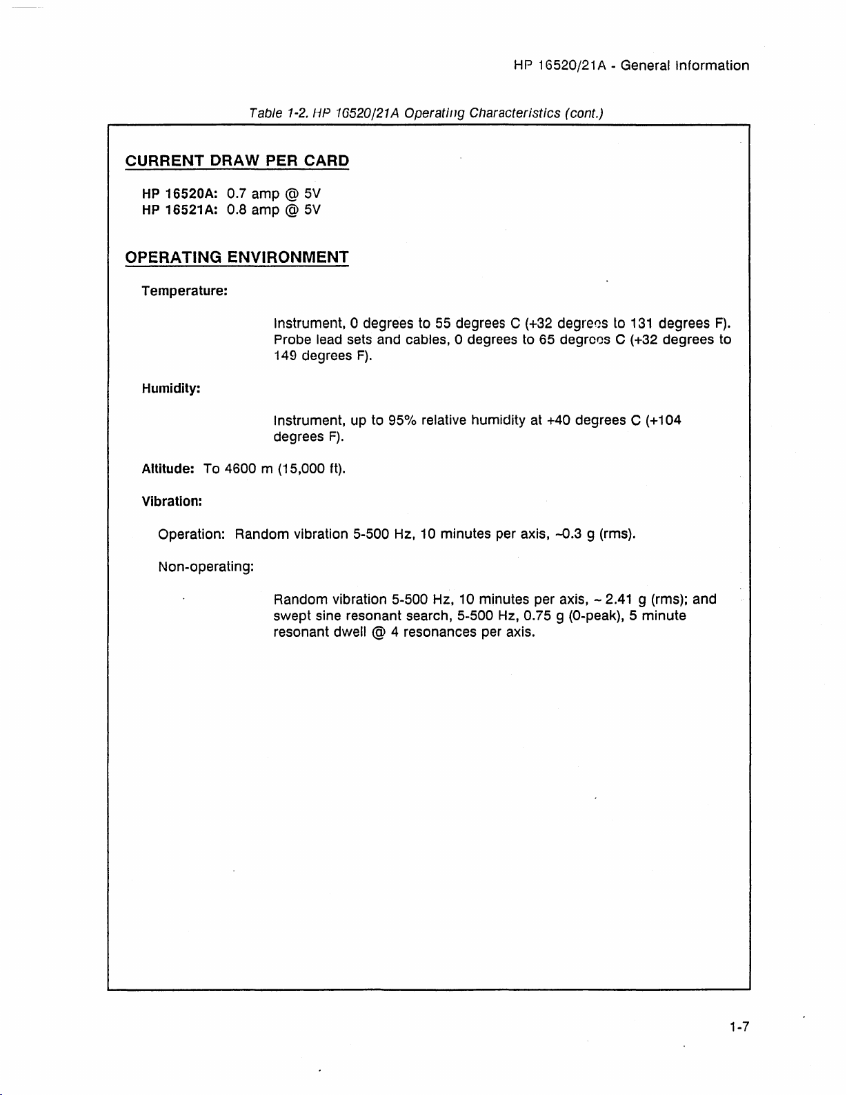
CURRENT
HP
16520A: 0.7
HP
16521 A: 0.8
ORA
W PER
amp
@ 5V
amp
@ 5V
CARD
OPERATING ENVIRONMENT
Temperature:
Instrument, 0 degrees to 55 degrees C (+32 degrees to
Probe lead sets and cables, a degrees to 65 degrees C (+32 degrees to
149 degrees
Humidity:
Instrument, up to
degrees
Altitude: To 4600 m (15,000 ft).
Vibration:
Operation: Random vibration 5-500 Hz, 10 minutes per axis,
F).
F).
95%
relative humidity at +40 degrees C (+104
-0.3
9 (rms).
131
degrees
F).
Non-operating:
Random vibration
swept sine resonant search,
resonant dwell @ 4 resonances per axis.
5-500 Hz, 10 minutes per axis, - 2.41 9 (rms); and
5-500 Hz, 0.75 9 (O-peak), 5
minute
Artisan Technology Group - Quality Instrumentation ... Guaranteed | (888) 88-SOURCE | www.artisantg.com
1-7
Page 18
HP 16520/21 A - General Information
Table
1-3.
Recommended
Test
Equipment.
INSTRUMENT
Osci.l
loscope
Multimeter
BNC
Adapter
50
Ohm
Feedthru
Probe
Lead
Grabbers
Set
CRITICAL
200
3
1/2
SPECIFICATIONS
MHz
Bandwidth
digit
Qty
Qty
Qty
Resolution
2
1
2
Qty 4
RECOMMENDED
MODEL
HP
54201A
HP
3468A
HP
1250-1032
HP
10100C
HP
10347A
HP
6969-0288 P
USE*
P,T
A
P
P
P
Pulse
Generator
Extender Board
BNC
Cable
P=Performance
*
100
KHz
Repetition
Overshoot:
No
5%
of
Substitute
(m-to-m) 9 inch (Qty2)
Tests
A=Adjustments
Rate
Amp.
HP
B161A
HP
16500-69004
HP
10502A
T=Troubleshooting
P
A,T
P
1-8
Artisan Technology Group - Quality Instrumentation ... Guaranteed | (888) 88-SOURCE | www.artisantg.com
Page 19
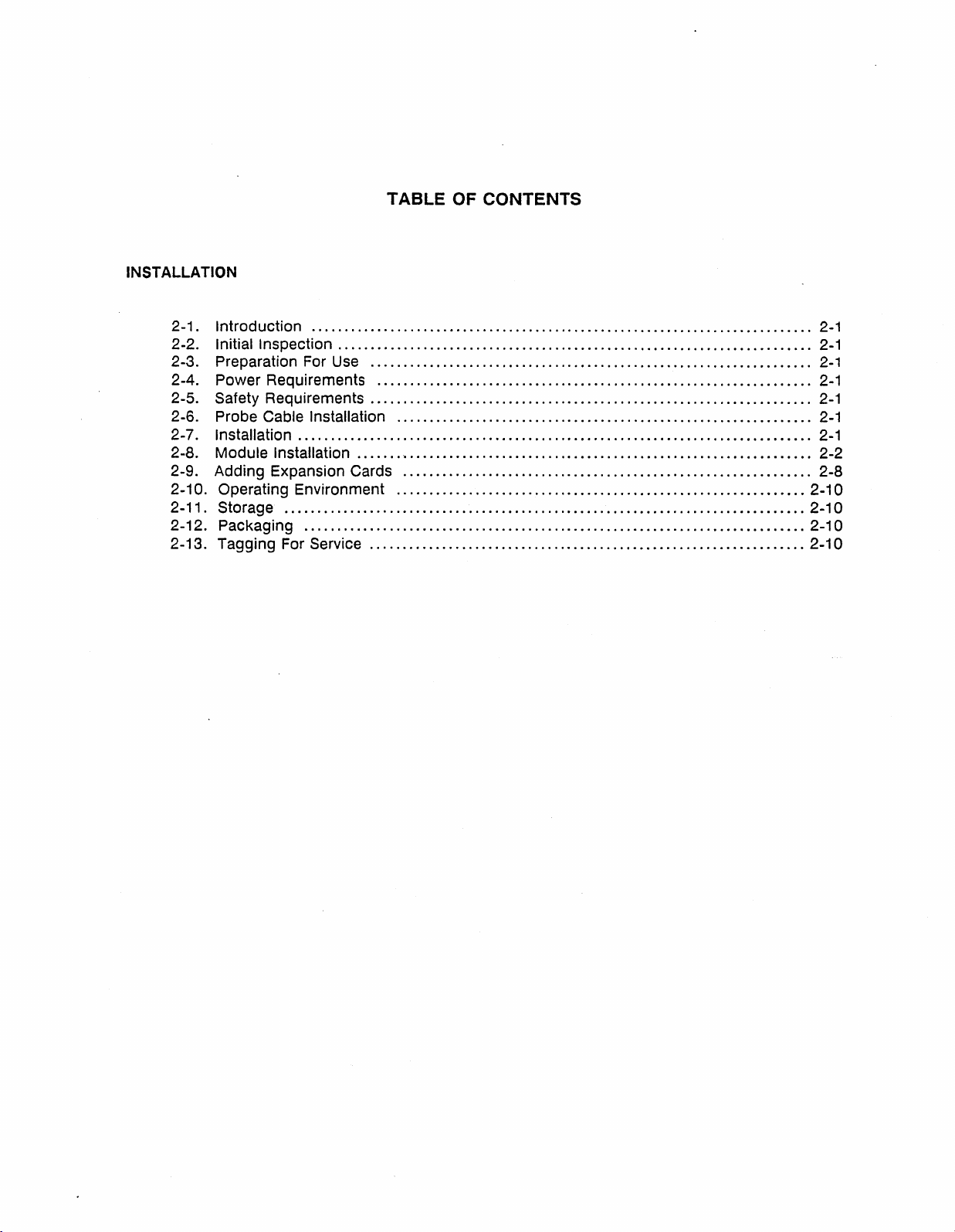
INSTALLATION
TABLE OF CONTENTS
2-1. Introduction
2-2. Initial Inspection
2-3. Preparation For
2-4. Power Requirements
2-5. Safety Requirements
............................................................................
........................................................................
Use
...................................................................
.............................
...................................................................
2-6. Probe Cable Installation
2-7. Installation
2-8. Module Installation
..............................................................................
....... ' ..............................................................
2-9. Adding Expansion Cards
2-10. Operating Environment
2-11. Storage
2-12. Packaging
2-13. Tagging For Service
...............................................................................
............................................................................
..................................................................
. . . . . . . . . . . . . . . . . . . . . . . . . . . . . . . . . . .
...............................................................
..............................................................
..............................................................
..
2-10
2-10
2-10
2-10
2-1
2-1
2-1
2-1
2-1
2-1
2-1
2-2
2-8
Artisan Technology Group - Quality Instrumentation ... Guaranteed | (888) 88-SOURCE | www.artisantg.com
Page 20
HP
16520/21 A - Installation
2-1. INTRODUCTION
This section explains, how to initially inspect
the
HP
16520/21 A Pattern Generator Module,
how to prepare it for use, storage and ship-
are
ment. Also included
installation.
procedures for module
2-2. INITIAL INSPECTION
Inspect the shipping container for damage. If
the shipping container or cushioning material
is
damaged, it should
tents of the shipment have been checked for
completeness and the module
checked mechanically and electrically. The
contents of the shipment should
the "ACCESSORIES SUPPLIES" paragraph located in Section
be
kept until the con-
has
been
be
as
listed
I.
in
SECTION
INSTALLATION
2-4. POWER REQUIREMENTS
All
power supplies required for operating the
HP
16520/21 A Pattern Generator Module are
supplied to the module through the backplane
connenctor.
2-5. SAFETY REQUIREMENTS
Specific warnings, cautions, and instructions
are
placed wherever applicable throughout the
be
manual. These must
phases
module. Failure to comply with them violates
safety standards of deSign, manufacture, and
intended use of this module. Hewlett-Packard
assumes no liability for the failure of the cus-
tomer to comply with these safety
requirements.
of
operation, service, and repair of the
observed during all
·11
Procedures for checking electrical perfor-
are
mance
container
damage or defect, or the instrument does not
pass the performance tests, notify the nearest
Hewlett-Packard office.
If the shipping container
cushioning material shows signs of stress,
notify the carrier
Hewlett-Packard office.
material
Hewlett-Packard office will arrange for repair
or replacement at Hewlett-Packard's option
without waiting for claim settlement.
in Section III. If the contents of the
are
incomplete, there
is
as
well
as
Keep
so
the carrier can inspection it. The
is
mechanical
damaged, or the
the
the shipping
2-3. PREPARATION FOR USE
I
WARNING
Read the Safety Considerations in the
of
front
before
module.
this manual and in Section I
installing or operating this
I
2-6. PROBE CABLE INSTALLATION
The
HP
16520/21A Pattern Generator Module
comes with probe cables installed by the fac-
If a cable
tory.
and
ECl,
REPLACEMENT" in Section
is
to
be
switched between TTL
refer to "PROBE CABLE
VI
of this manual.
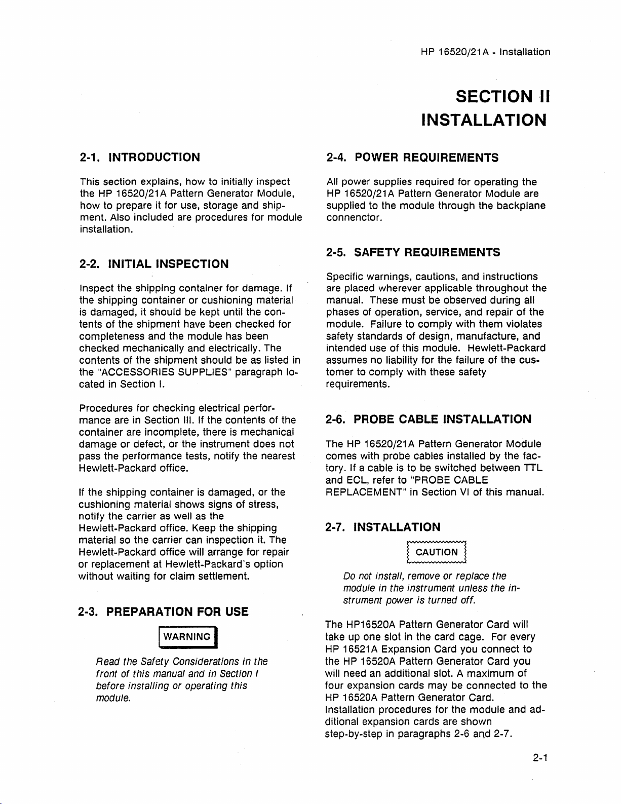
2-7. INSTALLATION
Do
not install, remove or replace the
module in the instrument unless the in-
is
strument power
The HP16520A Pattern Generator Card will
take up one slot in the card cage. For
HP
16521
A Expansion Card you connect to
the
HP
16520A Pattern Generator Card you
an
will need
four expansion cards may
HP
16520A Pattern Generator Card.
Installation procedures for the module and additional expansion cards
step-by-step
additional slot. A maximum of
in
turned off.
be
connected to the
are
shown
paragraphs 2-6 and 2-7.
every
Artisan Technology Group - Quality Instrumentation ... Guaranteed | (888) 88-SOURCE | www.artisantg.com
2-1
Page 21

HP
16520/21 A - Installation
2·8. MODULE INSTALLATION
If you
are
installing the
card and one or more expansion cards),
an
cards to
existing module, follow the procedure "ADDING
2-9.
The
effects of
ponents.
service
HP
16520/21 A Pattern Generator Module (one master card or one master
ELECTROSTATIC
Use
grounded wrists traps
to
this
module.
follow this procedure. If you
EXPANSION
DISCHARGE
and
mats
can
when
damage
performing
are
adding more expansion
CARDS" in paragraph
electronic
any
com-
kind of
INSTALLATION
CONSIDERATIONS:
• Cards or filler panels below the empty slots intended for the module installation do not
have to
•
You
• If previously installed modules prevent proper installation, they must
card cage.
be
removed.
will need only one intercard connecting cable for any installation configuration.
be
repositioned in the
See
figure
2-1
.
• To maintain the channel-to-channel skew and adequate intercard signal quality, the short-
be
est intercard connecting cable should
more than two slots away from the master card.
Figure
2-1
is
a guide in choosing the correct intercard connecting cable and illustrates the expan-
sion card position relative to the master card.
MASTER
ANO
EXPANSION
CARD
ORIENTATION
E~_I~J
EXPANSION
used and the expansion cards should
See
figure 2-1.
Use
this guide at step d in the following procedure.
EXPANSION
EXPANSION
EXPANSION
be
no
2-2
MASTER
AHV
SLOT
SLOT
SELECTION
WASTER
J
IlASTER
EXPANSION
At((
TWO
ADJACENT
Artisan Technology Group - Quality Instrumentation ... Guaranteed | (888) 88-SOURCE | www.artisantg.com
SLOTS
WASTER
EXPANSION
ANY
ADJACENT
Figure
THREE
2-1.
SLOTS
Installation
WASTER
EXPANSION
ADJACENT
Guide
EXPANSION
EXPANSION
At((
FOUR
SLOTS
WASTER
ALL
SLOTS
18520/EX07
Page 22
HP
PROCEDURE:
a.
Turn instrument power switch off, unplug power cord and disconnect any input or output connections.
b. Starting from the top, loosen thumb screws on filler panel(s) and card(s).
16520/21 A - Installation
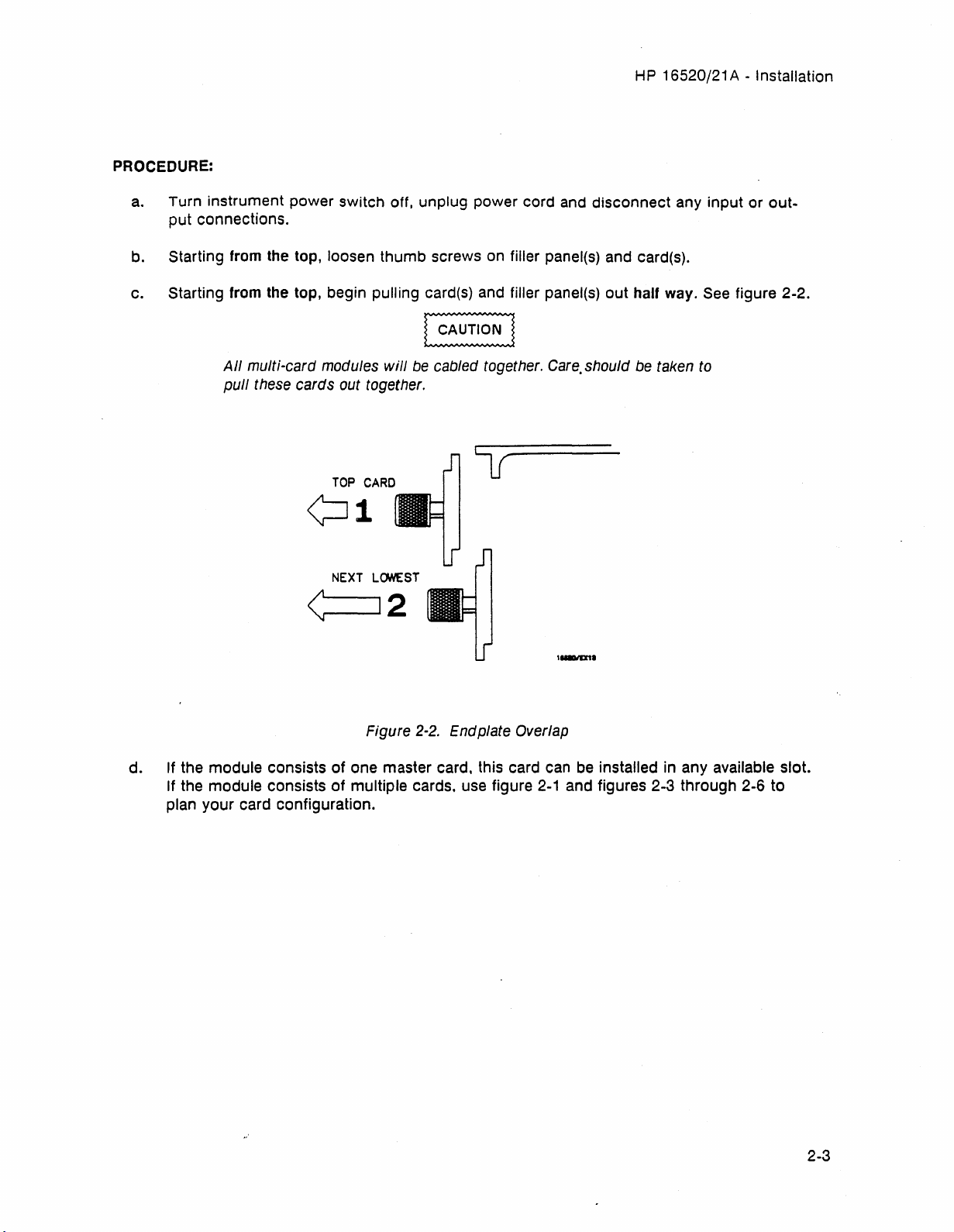
c. Starting from the top, begin pulling card(s) and filler panel(s) out half way.
All
multi-card modules
pull
these cards out together.
TOP
will
CARD
be
cabled together.
Care.
should be taken to
¢:J1
NEXT
LCNlEST
<:
12
Figure
2-2.
Endplate Overlap
lu.ID11
See
figure 2-2.
d. If the module consists
If the module consists
plan your card configuration.
Artisan Technology Group - Quality Instrumentation ... Guaranteed | (888) 88-SOURCE | www.artisantg.com
of
one master card, this card can
of
multiple cards, use figure
be
installed in any available slot.
2-1
and figures 2-3 through 2-6 to
2-3
Page 23
HP
16520/21 A - Installation
[Q]~o
I·
I
,.
~o
[Q]~o
I·
I
I·
~o
[Q](IDo
I·
<D
sa
<D
8..
CD
m
·
·I~
•
r.
I.
~o·l.
m
·
·I~
•
~
I.
oc::::J}o
·1.
m
·
·I~·
-
Irc::::==,
~.~I
• •
-
Irr:::::=:,
o •
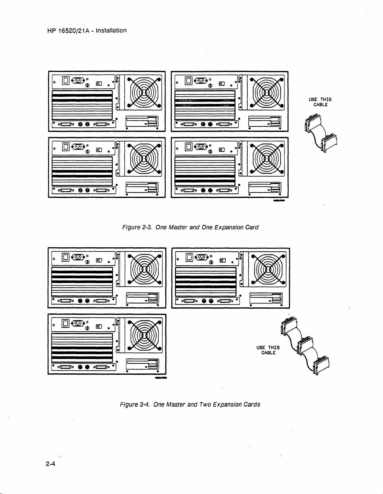
Figure
~.
~.=nl
B.
2-3.
One
I·
-1III
I·
Master
I·
[Q]~o
[Q]~o
[Q]~o
and
<D
<D
One
Expansion
<D
lID
.
·I~
•
r.
-
lID
.
·I~
•
r.
-
Card
lID
.
·I~·
-
USE
CABLE
THIS
I
Ie
oc::::::l1o
[Q]~~
I·
••
<D
oc::::J}o
lID
·
•
r·
-
I.
P'
·1.
·I~·
•
r.
~.4\1
• •
E3.
I.
~.
..
~.l
•
[.
-
i
Ic::::'
===;.EJ::::iji
• •
USE
I
THIS
CABLE
-
~,.
~oc::::J}~o
~.~.~oe:::::l1~o~l
i
reI'
==.==EJ:n11
• •
Figure
2-4.
-
One
Master
and
Two
Expansion
Cards
2-4
Artisan Technology Group - Quality Instrumentation ... Guaranteed | (888) 88-SOURCE | www.artisantg.com
Page 24

HP
16520/21 A - Installation
(g]~o
I·
(I)
lID
.
'I~'
-
r-
1
~
~~I.
,-
oc::::J1o
CD CD
oc::::J1o
-,.
-
f==i
=:=nl.'1
E3.
- -
[QJ(Wo
I·
CD
lID
.
·I~·
-
[-
-
,- oc::::J1o
••
oc::::J1o
Figure
-,
2-5.
-
One
Master
-
-
and
Three
USE
THIS
CABLE
Expansion Cards
[QJ~o
I·
1
..
----I.
,-
oc.t=:J1o •
lID
CD
0)
oe::::l1o
Figure
.
2-6.
'I~
.-
r-
-
,rc::::.
-,.
==.:::Iil'1
E3.
. -
-
One
Master
and
USE
CABLE
Four
Expansion Cards
THIS
2-5
Artisan Technology Group - Quality Instrumentation ... Guaranteed | (888) 88-SOURCE | www.artisantg.com
Page 25
HP
16520/21 A - Installation
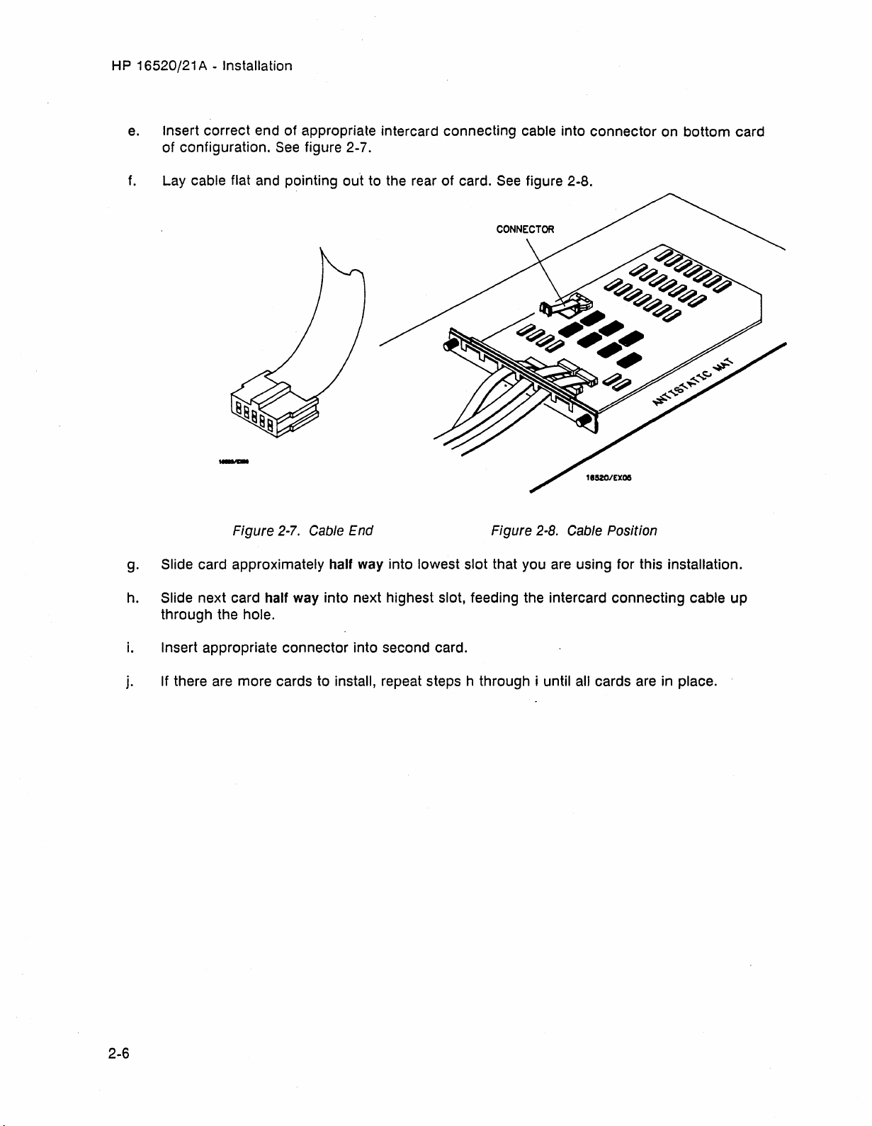
e.
Insert correct end of appropriate intercard connecting cable into connector on bottom card
of configuration.
f.
Lay cable flat and pointing out to the rear of card.
See
figure 2-7.
See
figure 2-8.
Figure
2-7.
Cable End Figure
2-8.
Cable Position
g. Slide card approximately half way into lowest slot that you are using for this installation.
h. Slide next card half way into next highest slot, feeding the intercard connecting cable up
through the hole.
i.
Insert appropriate connector into second card.
j. If there
are
more cards to install, repeat steps h through i until all cards are in place.
2-6
Artisan Technology Group - Quality Instrumentation ... Guaranteed | (888) 88-SOURCE | www.artisantg.com
Page 26
HP
16520/21 A - Installation
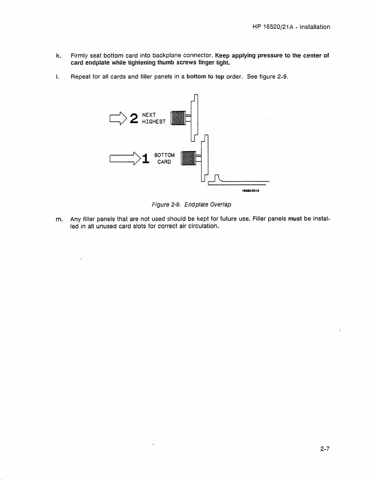
k.
Firmly seat bottom card into backplane connector. Keep applying pressure to the
card endplate while tightening thumb screws finger tight.
I.
Repeat for
all
cards and filler panels in a bottom to top order.
See
figure 2-9.
NEXT
HIGHEST
BOTTOM
CARD
11AD1D1.
center
of
m. Any filler panels that are
all unused card slots for correct air circulation.
led in
Figure
not
used should be kept for future use. Filler panels must be instal-
2-9,
Endplate Overlap
Artisan Technology Group - Quality Instrumentation ... Guaranteed | (888) 88-SOURCE | www.artisantg.com
2-7
Page 27
HP
16520/21 A - Installation
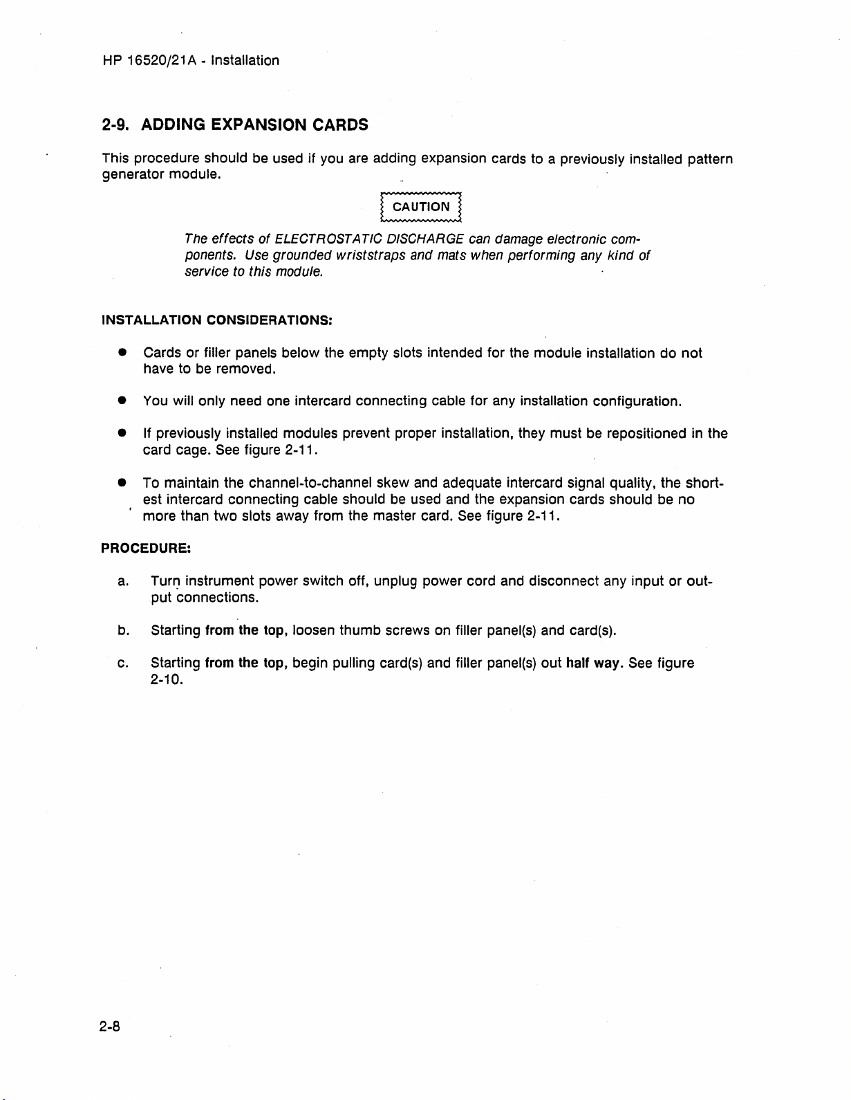
2·9. ADDING EXPANSION CARDS
This procedure should be used if you
are
adding expansion cards to a previously installed pattern
generator module.
The effects
ponents. Use grounded
service to this module.
INSTALLATION CONSIDERATIONS:
• Cards or filler panels below the empty slots intended for the module installation do
have to
be
removed.
of
ELECTROSTA
TIC
DISCHARGE can damage electronic com-
wriststraps
and
mats
when performing any
kind
of
not
• You will only need one intercard connecting cable for any installation configuration.
• If previously installed modules prevent proper installation, they must be repositioned in the
card cage.
See
figure
2-11
.
• To maintain the channel-to-channel skew and adequate intercard signal quality, the shortest intercard connecting cable should
more than two slots away from the master card.
PROCEDURE:
be
used and the expansion cards should
See
figure 2-11.
be
no
a.
Turr~
instrument power switch off, unplug power cord and disconnect any input or out-
put connections.
b. Starting from the top, loosen thumb screws on filler panel(s) and card(s).
c. Starting from the top, begin pulling card(s) and filler panel(s) out half way.
2-10.
See
figure
2-8
Artisan Technology Group - Quality Instrumentation ... Guaranteed | (888) 88-SOURCE | www.artisantg.com
Page 28
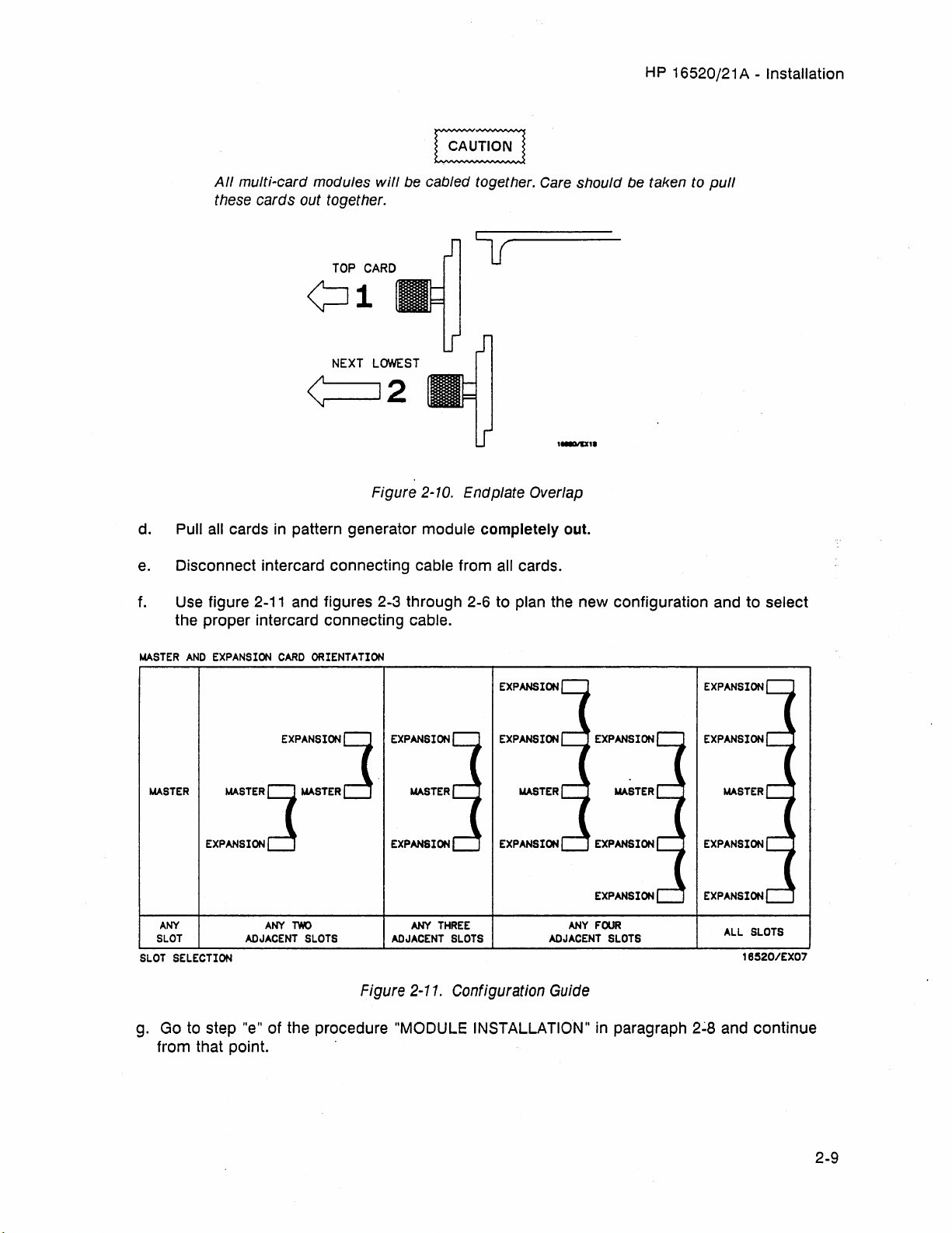
All
multi-card modules
these cards out together.
will
¢Jl
NEXT
LOWEST
HP
be
cabled together. Care should be taken to
16520/21 A - Installation
pull
<
d. Pull
e.
f.
MASTER
MASTER
all
cards
in
pattern generator module completely out.
Disconnect intercard connecting cable from
Use
figure
2-11
and figures 2-3 through 2-6 to plan the new configuration and to select
the proper intercard connecting cable.
AND
EXPANSION
MASTER
EXPANSION
CARD
ORIENTATION
EXPANSION
LJ
.......
c!
TER
12
Figure 2-10. Endplate Overlap
LJ
EXPANSION
c!
EXPANSION
.......
TER
aI/
cards.
EXPANSION
EXPANSION EXPANSION
MASTER MASTER
EXPANSION
EXPANSION
At-N
SL.OT
SLOT
SELECTION
g. Go to step "e" of the procedure "MODULE INSTALLATION"
from that pOint. .
Artisan Technology Group - Quality Instrumentation ... Guaranteed | (888) 88-SOURCE | www.artisantg.com
At-N
ADJACENT
TWO
SLOTS
At-r(
ADJACENT
Figure 2-11. Configuration Guide
THREE
SLOTS
ANY
ADJACENT
EXPANSION
FOUR
SLOTS
in
paragraph
ALL
16520/EX07
2~8
and continue
SLOTS
2-9
Page 29
HP
16520/21 A - Installation
2-10. OPERATING ENVIRONMENT
The operating environment
1-2.
Note the non-condensing humidity limitation. Condensation within the instrument can
cause poor operation or malfunction.
Protection should
condensation.
The
HP
16520/21 A will operate
tions within the temperature and humidity
range given in table 1-2. However, reliability
enhanced by operating the instrument within
the
following ranges.
Temperature:
Humidity:
be
+20 to +35° C
20%
to
80%
is
listed
in
table
provided against internal
at
all
specifica-
(+68
to +95°
non-condensing
F)
2-11. STORAGE
The module may
vironments within the
Temperature:
Humidity:
Altitude:
Feet)
The module should also
temperature extremes, which cause condensation on the module.
be
stored or shipped
following limits:
_40°
C to +75° C
Up
to 90% at 65°C
Up
to 15,300 meters (50,000
be
protected from
in
en-
is
2-12. PACKAGING
Follow these general instructions for repacking
the module with commercially available
materials.
• Wrap module in anti-static plastic.
•
Use
a strong shipping container. A
double-wall carton made of
is
material
•
Use
70-to-100 mm (3-to- 4 inch) thick around
all
sides of the module to provide firm
cushioning and prevent movement inside
the container.
•
Seal
• Mark shipping container FRAGILE to ensure careful handling.
•
In
any correspondence, refer to module
by model number and board number.
2-13. TAGGING
If the module
Hewlett-Packard office for service or repair, attach a tag with your name and address, the
complete board number, and a description of
the service required.
adequate.
a layer of shock-absorbing material
shipping container securely.
FOR
SERVICE
is
to
be
shipped to a
350 lb. test
2-10
Artisan Technology Group - Quality Instrumentation ... Guaranteed | (888) 88-SOURCE | www.artisantg.com
Page 30

PERFORMANCE TESTS
TABLE
OF
CONTENTS
3-1. Introduction
3-2. Recommended Test Equipment
3-3. Test Record
3-4. Performance Test Interval
3-5. Performance Test Procedures
3-6. Data Period Accuracy Test
3-7. Duty
Cycle Test
............................................................................
............................................................................
............................................................
............................................................
........................................................................
.......................................................
.........................................................
3-1
3-1
3-1
3-1
3-1
3-2
3-8
Artisan Technology Group - Quality Instrumentation ... Guaranteed | (888) 88-SOURCE | www.artisantg.com
Page 31

H P 16520/21 A - Performance Tests
SECTION III
3·1. INTRODUCTION
The procedures
generator's electrical performance using the
specifications listed in Section I
mance standards.
without access to the interior of the instrument.
can
results.
At
the end of this section
be
used
in
this section test the pattern
as
the perfor-
All
tests can
as
a record of performance test
be
performed
is
a form that
3·2. RECOMMENDED TEST
EQUIPMENT
Equipment recommended for performance
tests
is
listed in table 1-3. Any equipment that
satisfies the critical specifications given in the
table may
models.
be
substituted for the recommended
PERFORMANCE
all
of the tested specifications and their acceptable limits. The results recorded in the
test record may
periodic maintenance and troubleshooting or
after repairs and adjustments have been made.
be
used for comparison in
TESTS
3·4. PERFORMANCE TEST INTERVAL
Periodic performance verification of the H P
16520/21 A Pattern Generator Module is
required
strument's performance should
ter it has been serviced, or if improper operation
formed before any performance verification
tests. Further checks requiring access to the
interior of the instrument are included in the
adjustment section, but are not required
the performance verification.
at
two year intervals. The in-
be
verified af-
is
suspected. Calibration should be per-
for
3·3. TEST RECORD
Results of performance tests may
in the Performance Test Record (table 3-1)
the end of the procedures. The test record lists
be
tabulated
at
3·5. PERFORMANCE TEST
PROCEDURES
All performance tests should
the instrument's environmental operating temperature and after a
is-minute
be
performed at
warm up.
Artisan Technology Group - Quality Instrumentation ... Guaranteed | (888) 88-SOURCE | www.artisantg.com
3-1
Page 32

H P 16520/21 A - Performance Tests
3-6. Data Period Accuracy Test
SPECIFICATION: ±
EQUIPMENT:
Oscilloscope
BNC Cable
BNC Adapter
Probe Lead Set
Grabber
DESCRIPTION:
The purpose of this test
slowest and fastest clock ranges. (For
PROCEDURE:
a.
(2)
Connect data output channel 0 and the corresponding ground from a selected output
data cable, to the oscilloscope
nally connected for either TTL or
2%
(of period) ± 1
...........................................................................
....................................................
......................................................................
........................................................................
........................
is
to verify the data period accuracy of the internal clock at its
ns
:.............
bes.t
as
shown
EeL.
"
.......................
. . . .
..
. . . . .
.. .. ..
. . . . . .
...
. .
results, terminate
in
figure 3-1. The output cables can
in~o
10
kQ,
OSCILLOSCOPE
...
10
..
pF)
..
HP
HP
HP
54201 A
HP
10502A
1250-1032
H P 10347 A
5959-0288
be
inter-
b.
Apply power to the
DATA
CABLE
Figure
D
~
..,/
DATA
CHANNEL
3-1.
Data
Period
HP
16500A and wait for system bootup.
Accuracy
ADAPTER
Test
Equipment
INPUT
Hookup
3-2
Artisan Technology Group - Quality Instrumentation ... Guaranteed | (888) 88-SOURCE | www.artisantg.com
Page 33

HP
16520/21 A - Performance Tests
c. From the startup screen shown in figure 3-2, touch the following
below:
1.
System
2.
Pattern Gen (If multiple
.....
_S.;.y_st_e_m_--'J
Cards
A
PATTERN
GENERATOR
MASTER
- 50
Mbit/s
6
PATTERN
C
D
E
GENERATOR
EXPANDER
HP
(configuratiOn)
Figure
3-2.
16520A Cards, pick one to
Controller
RS-232C
~
Printer
Startup Screen
fields in the sequence
be
tested)
d. In the Format screen, touch Clock field and set to Internal
Pat
tern
Gen
..-="""""
......
(PO"ij'S)
l.!....!J
A ) (
Pol
(
ITTLnpu t )..
P d
ht.
2.0 3 ..
Figure
Format
A3
0 7
P d
ht.
......
3-3.
A2
----..
'--
__
P d
65
DE¥ACHED
0 7
......
Clock Field
.,/
0 7
E)
r;::::::)
~
Pod
DETACHED
......
as
shown in figure 3-3.
( Run
( ]
Symbols
65
Pod
64
DETACHED
0 7
......
0
Artisan Technology Group - Quality Instrumentation ... Guaranteed | (888) 88-SOURCE | www.artisantg.com
3-3
Page 34

HP
16520/21 A - Performance Tests
e.
Touch Period and
set
Pettern
Internal clock to 200
Gen
A ) ( Formet
J.Ls
as
20
50
100
200
500
2 us
5 us
Figure 3-4. Clock Period Screen
shown
ns
ns
ns
ns
ns
1 us
in
figure 3-4.
f. Touch channel assignment field for the selected input cable.
Pet
tern
Gen
~
STROBE
DATA
Off
g.
Select data output channel 0
Pe t tern
A ) ( Formet
Pod
A3
•
Pol
tE
TTL
•
2.0 3 ..
•
••
•••
G"'§§§
Figure
3-5.
as
Gen
A )
Formet
'--_--'
Pod
TTL
7
.....
0
Channel
shown
r----
_____
A2
Pod
DETACHED DETACHED DETACHED
0 7
......
I I • • • • • • •
Assignment Field
in
figure 3-6. Touch Done.
B6
......
0 7
~
(Strobes)
Pod
B5
......
•••••
~
0
I I • I
;:;==:-:=---..
Off
1"':::c::i:;;;:j;:::)...c.hr~d1
aD
(--C-LE-A--"'R)
( DONE) § §
(
Strobes)
Pod
65
.
~~:~~~~g
See
figure 3-5.
(
Run
(Symbols)
Pod
B~
7
......
0
•••••
I
(
Run
(SymbO
IS)
Pod
64
~~:~~~~g
Figure
h. Touch Format, then touch Listing.
3-4
Artisan Technology Group - Quality Instrumentation ... Guaranteed | (888) 88-SOURCE | www.artisantg.com
3-6.
Data
Channel
Select
Page 35

i.
From the listing screen, program the pattern generator
HP
16520/21 A - Performance Tests
as
follows:
Touch program field
1.
8
EJ
c::D
B
2.
Touch 1
as
shown
Autoroll
EJ
as
Instr
shown
(
)
(STROBE
Listing
in
figure 3-7.
)~
~~
***
:TART
I
.*.
QFb~:k:RAMI
10_
No
OF
P M *
in
figure 3-8, then touch Done.
Instr
***
••
Figure 3-7. Program Field
~~
~~
Run
(
Run
(
3.
Touch Insert
as
c::D
-
Figure
shown in figure 3-9.
Listing
Instr ) (STROBE
)
~
~~
u.
:TART
I
**.
No
OF
Figure
OF~RAM
~
0
M
•••
3-9.
.**
c::E::J
3-8.
Numeric
Insert New Program Line
Entry
3-5
Artisan Technology Group - Quality Instrumentation ... Guaranteed | (888) 88-SOURCE | www.artisantg.com
Page 36

HP
16520/2'1 A - Performance Tests
4. Touch program
~=~:===::..~(~L=l=s=t1~ng~
EJ
B
CJJ
5.
Enter
Os
as
shown in figure 3-11, then touch
(
Pettern
field
•••
Ln
Ins
START
END
Gen
Ins
as
shown
tr
) (
STROBE
~~
Or
PROGRAM
OF
~~.~
Figure
A ) (
tr
Listing
)
(STROBE)
in
figure 3-10.
)
~
•••
3-10.
._
~~
Program Field
Done.
..
(
Run
Run
6.
Repeat steps 1 through 5 until there
ding with a zero
Pettern
(0).
See
Gen
Ins
A ) (
tr
figure 3-12.
) (
STROBE
~~
•••
START
Or
PROGRAM
Merge u 00
B
~I
~
•••
~~cb
END
bF~
Figure
Figure
Listing
0
3-11.
Numeric Entry
is
a short program starting with a one
)
~
•••
01
01
00
••
.3-12.
Example Program
~~
(
Run
(1)
and en-
3-6
Artisan Technology Group - Quality Instrumentation ... Guaranteed | (888) 88-SOURCE | www.artisantg.com
Page 37

HP
16520/21 A - Performance Tests
j. Touch
Run,
then drag finger to Repetitive
Pottern
Gen A ) (
'---
_____
listing
J~
~
as
shown in figure 3-13.
~,...:..:...:...:..:....:
..........
_
~
Figure 3-13. Run Repetitive Mode
k. Using the oscilloscope, measure pulse period at 50% point on waveform.
I.
The pulse high time and low time should each measure between 196
m. Touch Stop.
n. Touch Listing, then touch Format.
o. Touch Period.
p. Change period to
q. Touch
Run,
20 ns.
then drag finger to Repetitive.
J.Ls
and 204
J..Ls.
r.
Using the oscilloscope, measure pulse period at 50% point on waveform.
s.
Pulse high time and low time should each measure between 18.6 ns and 21.4 ns.
t. Touch Stop.
Note
This test arbitrarily selects data channel 0 on
If
desired, other output channels and cables may
one
of
the data output cables.
be
substituted or added to
this procedure.
Artisan Technology Group - Quality Instrumentation ... Guaranteed | (888) 88-SOURCE | www.artisantg.com
3-7
Page 38

HP
16520/21 A - Performance Tests
3-7. Duty Cycle Test
SPECIFICATION: 10 ns minimum high time; 10 ns minimum low time
EQUIPMENT:
Oscilloscope
Pulse Generator
BNC Cable
BNC
Adapter
50 Ohm
Probe Lead Set
Grabbers
DESCRIPTION:
The purpose of this test
high and low times of the user supplied clock. (For best results, terminate into 10 kn,
PROCEDURE:
a.
Connect test equipment
...........................................................................
........................................................................
(2)
.........................................................................
(2)
...............................................................
Feedthru
(4)
.....................................................................
........................................................................
.......................................................................
is
to
verify that the internal clock circuits will respond to the
as
shown in figure 3-14.
,
....
OSCILLOSCOPE
D
PULSE
GENERATOR
HP 54201 A
H P 8116A
HP
10502A
HP
1250-1032
HP
10100C
HP
10347A
HP
5959-0288
minimum
10
INPUT
pF)
OUTPUT
-
GROUND
CLOCK
INPUT
Figure 3-14. Duty
b. Apply power to the 16500A and wait for system bootup.
c. Set pulse generator for a 50 MHz square wave, 50% duty cycle, and an amplitute of 5
Volts.
3-8
Cycle
Test
Equipment
Hookup
BNC
ADAPTER
Artisan Technology Group - Quality Instrumentation ... Guaranteed | (888) 88-SOURCE | www.artisantg.com
Page 39

HP
16520/21A - Performance Tests
d. From the startup screen shown
sequence below:
1. System
2.
Pattern
(,-
__
S_ys_t_em
A
PATTERN
MASTER -50
B
PATTERN
EXPANDER
C
D
E
Gen
(If multiple
__
Cerds
GENERATOR
GENERATOR
.,)
Mbit/s
(cant
Figure 3-15. Startup Screen
in
figure 3-15, touch the following field
HP
16520A Cards, pick one to
iguretion)
Controller
RS-232C
LJ
Printer
be
in
tested)
the ordered
e.
Touch Input field to set input level to
(
Pe t tern
Gen A ) (
r-==="""I(
f.
Touch Clock field and set to External
(
r===-",(
P')t
tern
:Od!)
Pol
Gen A ) (
:Od!)
Pol
2.0 3 ..
2.03
TIL
as
shown
Formet
_
Pod A3 Pod
TTL TTL
0 7
Clack
Interne!
......
A2
0 7
,-----.
"--
__
Pod
66
DETACHED
......
Figure 3-16. Set TTL Level
as
shown
Formet
(I~t
P~
A3
..
0 7
)_
P~
......
,----"'"
A2
D"~-~~-C-~~-D--'D~~~C~~D
0 7
......
in
figure 3-16.
~
~
r'
~
PoC!
65 Pod
DETACHED
0 7
......
in
figure 3-17.
~
0 7
......
0 7
0
( Run
( )
Symbols
6.:1
DETACHED
......
( Run
(
Symbol
Pod
6.:1
DETACHED
7
......
0
s)
0
Figure 3-17. Clock Field
Artisan Technology Group - Quality Instrumentation ... Guaranteed | (888) 88-SOURCE | www.artisantg.com
3-9
Page 40

HP
16520/21 A - Performance Tests
g. Touch Divide field and set to By
Pettern
Gen
A ) ( Formet
h.
Touch channel assignment field for the selected output pod.
Pet
tern
Gen
A J ( Formet
1.
See
figure 3-18.
Pod
DETACHED
7
......
Figure 3-18. Divide
B6
0 7
By
,..----
Pod
A2
Pod
I(Lebe!] I
STROBE
I
DATA
POd
A3
•
Pol
tE
TTL TTL
•
2.0 3 ..
•
••
~""ggg
7
......
0
••••
0 7
B6
DETACHED
......
0 7
• • • • • • • • , • • • • • • • •
(E2J
Pod
DETACHED
......
1 Field
(E2J
......
Pod
DETACHED
......
B5
0
B5
0 7
(
Run
(
Symbol
Pod
B~
DETACHED
7
......
0
See
figure 3-19.
(
Run
{SymbolS]
Pod
B~
DETACHED
......
0
••• I •••
S )
Figure 3-19. Channel Assignment Field
i.
Select data output 0
(
Pe t tern
as
shown in figure 3-20. Touch Done.
Gen
A )
Formet
;=::::::--:=--..
Lebel
STROBE
DATA
Of f
j. Touch Format, then touch Listing.
("'--C-LE-A---R
Figure 3-20. Data Output Select
(E2J
,..----
aD
J ( DONE] g g
......
Pod
B5
.
~~:~~~~g ~~:~~~~g
(
(
Run
Symbol
Pod
S )
B.::I
3-10
Artisan Technology Group - Quality Instrumentation ... Guaranteed | (888) 88-SOURCE | www.artisantg.com
Page 41

H P 16520/21 A - Performance Tests
k.
Perform step i in paragraph 3-6, "DATA PERIOD ACCURACY TEST" for a program
shown in figure
3-21
Merge
EJ
~I
~
•••
•••
.
START
eND
OF
OF
PROGRAM
0
..
..
I~~
p~
•••
01
00
01
00
~
••
Figure 3-21. Example Program
I.
Touch
Run,
then drag finger to Repetitive a shown in figure 3-22.
as
Figure 3-22. Run Repetitive
Mode
m. Set oscilloscope timebase to display a pulse stream.
n. Look for a 25 MHz square wave pulse stream with approximatly 20 ns low times and 20
ns high times.
ternal clock
See
figure 3-23. The presence
circuits are working.
t+
of
2ena 2ena .
H1GH
..,..
LON-+I
a consistent pulse stream verifys the ex-
I
....
o.
Touch Stop.
141--
Figure
3-23.
.....
· 4ena
25
--
MHz
...
~
... I
'
........
Square
Wave
3-11
Artisan Technology Group - Quality Instrumentation ... Guaranteed | (888) 88-SOURCE | www.artisantg.com
Page 42

HP 16520/21 A - Performance Tests
Table 3-1. Performance Test Record
Hewlett-Packard
Model
Pattern
Board
16520/21A
Generator
No.
Paragraph
No
3-5
Data Period Accuracy @
Data Period Accuracy
Card
Recommended
Interval
Test
Calibration
24
Months
--
200
us
@
20
ns
Tested
Work
Date
by
Order
Tested
No.
Results
Minimum = 196
Maximum = 204
Actual
Minimum = 18.6
Maximum = 21.4
Actual
us
us
ns
ns
3-12
3-6
Duty Cycle
Is
Yes
No
pulse
stream
visible
?
Artisan Technology Group - Quality Instrumentation ... Guaranteed | (888) 88-SOURCE | www.artisantg.com
Page 43

ADJUSTMENTS
TABLE
OF
CONTENTS
4-1. Introduction
4-2. Calibration Interval
4-3. Safety Requirements
4-4. Recommended Test Equipment
4-5. Extender Board Installation
4-6. Instrument Warmup
4-7. Adjustment And Calibration Check
............................................................................
.....................................................................
...................................................................
.......................................................
............................................................
....................................................................
....................................................
4-1
4-1
4-1
4-1
4-1
4-4
4-4
Artisan Technology Group - Quality Instrumentation ... Guaranteed | (888) 88-SOURCE | www.artisantg.com
Page 44

HP
16520/21A - Adjustments
SECTION IV
ADJUSTMENTS
4-1. INTRODUCTION
This section provides information
calibrate the module and how to
just and warm up the module. Also included
in
this section
recommended test equipment and a procedure
for installation of the extender board.
are
equipment setups, a list of
on
when to
calibrate, ad-
4-2. CALIBRATION INTERVAL
To maintain proper operation of the H P
16520/21 A Pattern Generator Module, calibra-
be
tion should
year intervals when the instrument
used under normal operating conditions.
instrument
day, it may have to
New modules
meet the specifications
this manual. Before any adjustments
made to the module, the performance tests in
Section
tests
ments
necessary, refer to the safety summary at the
front of this manual.
III
are
are
performed
is
used more than one shift per
are
preadjusted
should
within specifications, then adjust-
not necessary. If adjustments
be
at
approximately two
is
being
If the
be
calibrated more often.
at
the factory to
listed
in
Section 1 of
are
done. If the performance
are
4-3. SAFETY REQUIREMENTS
Specific warnings, cautions, and instructions
are
placed wherever applicable throughout the
manual. These must
phases of operation, service, and repair of the
module. Failure to comply with them violates
safety standards of design, manufacture, and
intended use of this module. Hewlett-Packard
assumes no
tomer to comply with these safety
requirements.
liability for the failure of the cus-
be.
observed during all
4-4. RECOMMENDED TEST
EQUIPMENT
Recommended adjustment test equipment
listed
in
table 1-3. Any eqUipment that satisfies
the critical specifications given in the table
may
be
substituted for the recommended
models.
-
is
4-5. EXTENDER BOARD
INSTALLATION
Before any adjustments or calibration checks
are
done, the H P 16520A Card must
led
on
an
extender board. The procedure for
this installation
is
on the next page.
be
instal-
Artisan Technology Group - Quality Instrumentation ... Guaranteed | (888) 88-SOURCE | www.artisantg.com
4-1
Page 45

HP
16520/21 A - Adjustments
Extender Board Installation (cant.)
The effects of ELECTROSTATIC DISCHARGE can damage electronic
Use
components.
kind
of
service to this instrument or the cards in it.
INSTALLATION CONSIDERATIONS:
grounded wriststraps and
mats
when performing any
• The extender board may
• Cards below the slot used by the extender board do not have to be removed.
• The probe cables do not have to
PROCEDURE:
a.
Turn instrument power switch off, unplug power cord and disconnect any input or out-
put connections.
b.
Starting from the top, loosen thumb screws on filler panel(s) and card(s).
c.
Starting from the top, begin pulling card(s) and filler panel(s) out half way.
All
multi-card modules
pull
these cards out together.
TOP
be
Installed
will
CARD
In
any
available slot
be
removed to adjust the
be cabled together. Care should be taken to
In
the card cage.
HP
16520A Card.
¢=J1
See
figure 2-1.
NEXT
<:
Figure
d. Pull module (one or more cards) to
connecting cable from the card(s).
4-2
Artisan Technology Group - Quality Instrumentation ... Guaranteed | (888) 88-SOURCE | www.artisantg.com
LOtYEST
12
4-1.
Card Endplate Overlap
be
serviced completely out and disconnect intercard
Page 46

HP
e.
Push all other cards part way into the card cage, but not completely in so they
in your way when you install the extender board.
f.
Slide extender board completely into card cage making sure it
backplane connecter.
HP
g. Plug
0
1
16520A Card into extender board.
[Q]~o
CD
lID
.
·I~
See
figure 4-2.
is
firmly seated in
-----------
16520/21 A - Adjustments
won't
be
r-
: .
~
-
Figure
Artisan Technology Group - Quality Instrumentation ... Guaranteed | (888) 88-SOURCE | www.artisantg.com
4-2.
Extender Board and Module
4-3
Page 47

HP
16520/21 A - Adjustments
4-6. INSTRUMENT WARMUP
Always adjust and check the calibration of the instrument at its environmental ambient temperature
and after a 15 minute warm-up.
4-7. ADJUSTMENT AND CALIBRATION CHECK
There is one calibration check on the
HP
16520A card. If calibration
justment to make. This reference is preset at the factory and
If, after referring to paragraph 3-4, "PERFORMANCE
suspected
DESCRIPTION:
This procedure will check and adjust the
EQUIPMENT:
as
a problem, perform the following procedure.
+5
TEST
INTERVAL", the reference voltage is
Volt reference for the
Multimeter
PROCEDURE:
a.
Connect the positive lead from the multimeter to
TP1
the location of the test points and the adjustable resistor, refer to figure 4-3.
is
out, there will be one ad-
normally should not need adjustment.
D/A
converter.
HP
3468A
and the negative lead to TP2. For
TP1
4-4
Figure
4-3.
Adjustment Pot Location
TP2
R5
Artisan Technology Group - Quality Instrumentation ... Guaranteed | (888) 88-SOURCE | www.artisantg.com
Page 48

HP
16520/21A - Adjustments
b. Set the multimeter to autorange and DC Volts.
c. Plug power cord In, turn Instrument power on, and walt for system bootup.
d. From the startup screen shown in figure 4-4, touch the following fields in order:
1. System
2. Pattern Gen (If multiple
3. Format
4. Listing
System
e.
Touch Delete.
See
figure 4-5.
HP
16520A cards, pick the one to
(configuretlOn)
~I
a
'-1r----t::===-W
Figure
4-4.
~
Startup
Screen
LJ
Pr
inter
be
adjusted)
(
Pettern
Gen
A ) (
Ins
Listing
tr
) (
STROBE
)
~
(:~~!~=)(!~)
( Run
~~
•••
START
OF
PROGRAM
-
Merge
EJ
~I
~
Artisan Technology Group - Quality Instrumentation ... Guaranteed | (888) 88-SOURCE | www.artisantg.com
•••
~~db
END
OF~··
0
..
Figure
•••
01
00
01
00
4-5.
Delete
Field
4-5
Page 49

HP
16520/21A - Adjustments
f.
Rotate knob counter clockwise until "START
and the program line field shows
Pet
tern
Gen A )
Instr ) (STROBE)
O.
See
L1sting
~~
figure 4-6.
~
OF
PROGRAM" comes down to midscreen
~E)
( Run
g. Touch Execute,
listing,
Figure
then Format.
4-6.
h. Touch Input, then touch User Defined.
Done.
Pettern
Gen A )
Formet
Figure 4-7. User Defined Field
i.
Touch Clock
to
set clock source to internal.
(
Pet
tern
Gen
ICLebeiJ
STROBE
DATA
A ) (
G:1J
•
•
I'
Pol
I
lE
Formet
I~~~~
(
POd
TTL
2.0 3 ..
•
••
~E2B§§§
) _
A3 Pod
7
0
••
••••
Program Une Field
See
figure 4-7. Set level to +9.9 Volts, then touch
( Run
( Symbol s )
See
figure 4-8.
TTL
......
E)
~======
.
A2
Pod
DETACHED
0 7
......
••
• • I • • •
B6
••
0
•
(Strobes]
Pod B5
DETACHED
7
......
••
• • • • • •
0 7
( Run
(Symbols)
B4
Pod
DETACHED
......
.,
•••
I
0
••
4-6
Figure
Artisan Technology Group - Quality Instrumentation ... Guaranteed | (888) 88-SOURCE | www.artisantg.com
4-8.
Internal Clock
Page 50

HP
16520/21A - Adjustments
j. Touch Period, then
(
Pettern
k.
Touch
Run,
then drag finger to Single.
200
ns.
Gen
A ) ( Formet
See
figure 4-9.
Figure
4-9.
Period Selection
See
figure 4-10.
20
50
Run
ns
10
us
ns
20
us
200 us
I
us
2
us
5
us
Pettern
After you have started the pattern generator, the
then very quickly change back to
taken.
I.
Read
the voltage displayed.
m. With a
reads
non-metallic adjustment tool, adjust the variable resistor
0.99 Volts
n. Set user defined
Gen
A ) (
:;=:::::-;::~
Figure
(±
0.001
V).
level
to -9.9 Volts and touch
4-10.
Run-Single Selection
Note
Run
Run.
This
is
the point the measurement
Run.
field will change to Stop,
is
R5
until the multimeter
Artisan Technology Group - Quality Instrumentation ... Guaranteed | (888) 88-SOURCE | www.artisantg.com
4-7
Page 51

HP 16520/21 A - Adjustments
o. Read the voltage displayed and note the difference between this reading and -0.99
Adjust R5 so this difference in halved (± 0.001 V).
Examples:
If reading is + 0.95
If reading
p. Turn
q.
Remove the HP 16520A Card from the extender board.
r.
At this point in the procedure, if you have multiple HP 16520A Cards to adjust, plug in
the next HP
s. If you have completed the adjustment on the HP 16520A Card(s), remove extender
board.
t. To reinstall the pattern generator module, go to steps d through m
"MODULE INSTALLATION".
Is
+ 0.97
off
instrument power, unplug power cable and disconnect all test equipment.
16520A card and repeat steps a through q.
V,
the difference is .04 V. Adjust R5 for + 0.97 V.
V,
the difference
Is
.02
V.
Adjust
R5
for + 0.98 y.
of
paragraph
2-8,
Volts.
4-8
Artisan Technology Group - Quality Instrumentation ... Guaranteed | (888) 88-SOURCE | www.artisantg.com
Page 52

REPLACEABLE PARTS
TABLE OF CONTENTS
5-1. Introduction
.............................................................................
5-2. Abbreviations. . . . . . . . . . . . . . . . . . . . . . . . . . . . . . . . . . . . . . . . . . . . . . . . . . . . . . . . . . . . . . . . . . . . . . . . .
5-3. Replaceable Parts List
5-4. Exchange Assemblies
5-5. Ordering Information
5-6. Direct Mail order System
.................................................................
..
. . . . . . . . . . . . . . . . . . . . . . . . .. . . . . . . . . . . . . . . . . . . . . . . . . . . . . . . . . . . .
...................................................................
..............................................................
..
..
5-1
5-1
5-1
5-1
5-1
5-2
Artisan Technology Group - Quality Instrumentation ... Guaranteed | (888) 88-SOURCE | www.artisantg.com
Page 53

5-1. INTRODUCTION·
HP
16520/21 A - Replaceable Parts
SECTION V
REPLACEABLE PARTS
This section contains parts and ordering information for the
Generator
designators and abbreviations used throughout
manual. Table 5-2 lists all replaceable
this
parts by reference designator.
Module. Table
HP
16520/21A Pattern
5-1
lists the reference
5-2. ABBREVIATIONS
Table
5-1
lists abbreviations used throughout
the manual.
abbreviations are used, one in
ters, the other partially or not capitalized.
did this because the abbreviations in the parts
list are always all capitals. However,
parts of the
are used with both
letters.
In
some cases two forms of the
all capital let-
We
in
other
manual other abbreviation forms
lower and uppercase
5-3. REPLACEABLE PARTS LIST
Table 5-2 lists replaceable parts and is organized
as
follows:
a.
Electrical assemblies in alphanumeri-
cal
order by reference designation.
d. Description of part.
e.
Check digit.
The
total quantity for each part
once at the first appearance of the part
ber
in
the list.
is
only given
num-
5-4. EXCHANGE ASSEMBLIES
Exchange assemblies are available when a
repairable assembly
Hewlett-Packard. These
on
set up
This
ty assembly with one that has been repaired,
calibrated, and performance verified by the
factory. The cost
of a new
Exchange assemblies are listed in a separate
section
have a part number in the form XXXXX-695XX
(where the new parts
Before ordering a
with your
procedures.
the Blue-stripe Exchange program.
allows the customer to exchange the faul-
assembly.
in
the replaceable parts table. They
local parts or repair organization for
is
returned to
assemblies have been
is
significantly less than that
would
blue-stripe assembly, check
be
XXXXX-665XX).
b.
Chassis-mounted parts in alphanumerical
designation.
c.
Electrical assemblies and their com-
ponents in alphanumerical order by
reference designation.
The information given for each part consists of
the
following:
a.
Complete reference designation.
b.
Hewlett-Packard part number.
c.
Total quantity (Qty) of instrument.
Artisan Technology Group - Quality Instrumentation ... Guaranteed | (888) 88-SOURCE | www.artisantg.com
order by reference
5·5. ORDERING INFORMATION
To
order a part listed in the replaceable parts
table, quote the Hewlett-Packard part number,
check digit, indicate the quantity required, and
address the order to the nearest
Hewlett-Packard office.
To order a part that
able
parts table, include the instrument model
number, instrument serial number, the description and function of the
parts required. Address the order to the
nearest
Hewlett-Packard office.
is
not listed in the replace-
pali, and number of
5-1
Page 54

HP
16520/21 A - Replaceable Parts
5-6. DIRECT MAIL ORDER SYSTEM
Within the
USA,
Hewlett-Packard can supply
parts through direct mail order. The advant-
are
as
ages
follows:
a.
Direct ordering and shipment from
Hewlett Packard Parts
Mountain View,
b.
No
maximum or minimum on any
California.
Center in
mail order (there is a minimum order
for parts ordered through local
Hewlett Packard offices when orders
require billing and invoicing).
Is
c. Prepaid transportation (there
a
small handling charge for each
order).
No
invoices - to provide these ad-
d.
vantages, check or money order
must
acco!'T1pany
each order.
Mall order forms and specific ordering information are available through your local Hewlett
Packard offices.
5-2
Artisan Technology Group - Quality Instrumentation ... Guaranteed | (888) 88-SOURCE | www.artisantg.com
Page 55

Table 5-1. Reference Designators and Abbreviations.
-assembly F
A
-fan;motor
B
-battery
BT
-capacitor
C
-diode;diode thyristor;
CR
varactor l
-delay line
Dl
-annunciator;lamp;LED P
08
-misc. electrical part
E
A
AID
AC
ADJ
AL
AMPL -amplifier
ANlG
ANSI
ASSY
ASTIG
ASYNCHRO
ATTEN -attenuator FM -foam;from
AWG
BAL
BCD
BD -board
BFR
BIN
BRDG
BSHG -bushing
BW
C
CAL
CC
CCW
CER
CFM
CH
CHAM -Chamfered
CHAN -channel
CHAR -character
CM
CMOS
CMR
CNDCT
CNTR -counter
CON
CO
CRT -cathode-ray tube
CW
0 -diameter
D/A
DAC
DARL
OAT
DBl
DBM
DC
CCCR
DEG
DEMUX -demultiplexer
DET -detector
DIA -diameter
DIP
DIV -division LKWR
DMA
DPDT
DRC
DRVR
-amperes
-analog-to-digital
-altarnating current
-adJust(,"ent) EXT -external MISC
-aluminum F -farads;metal film
-analog
-American National composition
Standarda
-assembly
-astigmatism
-asynchronous FL
-American wire gauge
-balance
-binary-code decimal product NPN
-buffer
-binary
-bridge
-bandwidth
-ceramic;cermet
(resistor) H
-calibrate;calibration HD -hardware
-carbon composition
-counterclockwise
-ceramic HGT
-cubic
-choke
-centimeter
-complementary metal- HV
-common mode rejection
-conductor
-connector IN
NT
-contact
-clockwise
-digital-to-analog
-digital-to-analog
converter
-darlington
-data
-double K
-decibel referenced
-direct
-decoder
-degree
-dual
-direct
-double.pole,
-DAC refresh controller meter(distance)
-driver
Inltitute
feet/minute
oxide-semiconductor HZ -Hertz
tolmW
current
in-line package
memory
access
double-throw M
-fuse
FL
-filter
H -hardware
-electrical connector
J
(stationary portion);jack
scoil;inductor
-misc. mechanical part
MP
-electrical connector
(moveable portion);plug
OWL
-dowel MFR
-emitter coupled logic
ECl
ELA8
-ela.tomeric
(resistor)
FC
-carbon film/
FD
-feed
FEM -female
-flip-flop
FF
-flat
FR
-front
-gain bandwidth oxide-semiconductor SIP -single in-line
FT
-full
FW
FXD
OEN
GND
GP
GRAT -graticule replaceable SPCL
GRV
HDND
HG
HLCl
HORIZ
HP -Hewlett-Packard
HP-IB -Hewlett·Packard
HR
1/0
IC
10
INCL
INCAND-incandescent
INP
INTEN -intensity POT -potentiometer TX -transmitter
INTl
INV -inverter PP -peak-to-peak
JFET -junction field- PPM -parts
JKT
l
lB
lCH
lCl
lED
lG
II
lK
lS
lV
MACH -machine
MAX
wave negative SKT
-fixed
-generator NRFR
-ground(ed)
-general purpose
-groove NUM
-henries;high OBD -order by detCription
-hardened
-mercury
-height
-helical
-horizontal
Interface
-hourIs) PF -picofarda THK
-high
voltage PI
-input/output
-integrated circuit array
-inside diameter
-inch
-include(s)
-input
-internal POZI -pozidrive U -micro( 1 0-6)
effect transistor
-jacket
-kilo(103)
-low
-pound
-latch
-local PT
-light-emitting PW -potted wirewound VF -voltage, filtered
diode
-long
-lithium RAM -random-access memory
-lock
-lock
washer
-low
power Schottky
-low
vOlt~e
-mega(10
-maximum
REFERENCE DESIONATORS
a
R
RT
S -switch;jumper breakdown diode
T -transformer W
TB -termInal board
TP
ABBREVIATIONS
MICPROC -microprocessor
MINTR
MLD -molded
MM
MO -metal oxide
MTG -mounting controlled rectifier
MTlC
MUX -multiplexer
MW
N -nano( 1 0-9)
NC
NMOS
NPRN
NSR
OCTl
00
OPAMP
OSC
P
P/O
PC
Bus
);megohms;
PCB
PO
Pl
PlA
PlST
PNP
POlYE
POS
PRCN
PREAMP -preamplifier
PRGMBl
PRL -parallel
PROG
PSTN
PWR
R-S
RECT
RET
RF
RGlTR
RGTR
RK
RMS -root-mean-square
HP
16520/21 A-Replaceable Parts
-translstor;SCR;
triode thyristor
-resiltor
-thermistor
-teet point
-manufacturer
-miniature
-miscellaneous
-millimeter
-metallic
-milliwatt
-no
connection SHF
-n-channel metal-
-negative-positive-
-neoprene
-not
recommended for
field replecement SLT -slot(ted)
-not
separately SOLD -solenoid
-numeric
-octal
-outside diameter
-operational amplifier
"oscillator
-plastic TA -tantalum
-part
of TBAX -tubeaxial
-printed circuit
-printed circuit board
-power
diSSipation
-plug
in
-plate(d) TP
-programmable logic TPG -tapping
-plastic
-positive-negative-
positiVI!!
-polyester TRN -turn(s)
-positive;position TTL -transistor-transistor
per million UNREG -unregulated
-precISion VA -voltampere
-programmable VAR -variable
-programmable oscillator
-position
-point
-power
-reset-set W
-rectifier
-retainer
-radio frequency
-regulator ZNR -zener
-register
-rack
-integrated circuit;
U
microcircuit
V
-electron tube; glow lamp
VR
-voltage regulator;
-cable
X
-socket
Y
-crystal unit(piezoelectric or quartz)
RND
ROM
RPG
RX
S
SCR
SEC
SEG
SEl
SGL
SI
Sl
SlDR
SO
SREG
SRO
STAT
STD -standard
SYNCHRO -synchronous
TC
TO
THO
THRU
TPl
TRANS
TRIG -trigger(ed)
TRMR -trimmmer
Ul
VAC
VCO
VDC
VERT
VS
WI
W/O
WW
XSTR
oC
OF
OK
-round
-read-only memory
-rotary
pulae generator
-receiver
-Schottky-clamped;
seconds(time)
-screw;silicon
-'econd(time);HCondary
-segment
-selector
-single
-shift
-silicon
package
-skirt
-slide
-solder
-special
-square
-shift
register
-service request
-static
-temp"erature coefficient
-time delay
-thread(ed)
-thick
-through
-test point
-triple
-transformer
-Underwriters Laboratory
-volt.ac
-voltage-controlled
-volt,dc
-vertical
-versus
-watts
-with
-without
-wirewound
-transIStor
-degree Celsius
(Centigrade)
-degree Fahrenheit
-degree Kelvin
Artisan Technology Group - Quality Instrumentation ... Guaranteed | (888) 88-SOURCE | www.artisantg.com
5-3
Page 56

HP 16520/21 A • Replaceable Parts
Table 5·2. Replaceable Parts
Reference
HP
Part
Designation Number
16520-13501 1
16520-69502
16521-69501
16520-61601
16520-61602 3
16520-61603 5
16520-69501 8
16515-40501 0
16515-40502 2
16500-22401
16520-62102
0515-0430
0515-0665 6
0510-0684
16500-29101
16520.94305
1650Q.41201
595~291
16520-61602
1650Q.41201
16521-88701 1 1 INTERCARD CONNECT CABLE KIT
051!HJ430
0515-0665
0510-0684 9 2
1650Q.29101
16521·94308
16515-40501 0
16515-40502
16500-22401
595~291
Qty. Description
CD
1 HP
1 HP
9
1 HP 16521A EXCHANGE
9
1
1
1 8 CHANNEL DATA CABLE
1 CLOCK
1
1 REAR PANEL STM
1
5 2
1 1 LEAD SET PURPLE 10347A
3
3
4
9
2
1 GROUND
6
1
1
3 3
9 1
3 6
6
3
3 3
4 M3 X 14 PH
6
1 GROUND
6
1 PATT. GEN. EXP LABEL
2
1 REAR PANEL STM
1
2
5 2
1
9
16520/21A OPER. SYS. DISC
16520A EXCHANGE ASSY.
HP
16520A
INPUT QUALIFIER PROBE CABLE
PROBE CABLE
INPUT
QUAL
PROBE KIT GREY
CLAMP.pANEL
SCREW
PANEL
MSPH M3 6 SMS10
M3
X 14 PH T10
RETAINING RING
SPRING
PATT. GEN LABEL
RIBBON CABLE
SERIAL TAG
HP
8 CHANNEL DATA CABLE
RIBBON CABLE
MSPH M3 6 SMS10
RETAINING RING
CLAMP·PANEL
PANEL
SERIAL TAG
10
16521A
10
no
SPRING
SCREW
CUP
CUP
Mfr Mfr Part
Code Number
ASSY.
.
5-4
.
Artisan Technology Group - Quality Instrumentation ... Guaranteed | (888) 88-SOURCE | www.artisantg.com
Page 57

SERVICE
TABLE OF CONTENTS
6-1. Introduction
6-2. Safety Requirements
6-3. Recommended Test Equipment
.............................................................................
...................................................................
.......................................................
6-4. Module Block Diagram and Theory of Operation
6-5. Pattern Generator Theory of Operation
6-6. Expansion Card Theory
6-7. Self Tests
6-8. Troubleshooting
...............................................................................
.................. : .....................................................
6-9. Card Replacement
6-10
..
Probe Cable Replacement
of
Operation
....................................................................
..............................
...............................................
.................................................
.....................................
-
.............................
6-1
6-1
6-1
6-1
6-3
6-4
6-5
6-9
6-32
6-35
Artisan Technology Group - Quality Instrumentation ... Guaranteed | (888) 88-SOURCE | www.artisantg.com
Page 58

6-1. INTRODUCTION
HP
16520/21 A - Service
SECTION VI
SERVICE
This section contains information for servicing
HP
the
Included
16520/21A Pattern Generator Module.
is
a block level theory of both cards
and procedures for self diagnostics and
troubleshooting.
If a card or cable
is
determined faulty, procedures are provided for
replacing the card or cable.
6-2. SAFETY REQUIREMENTS
Specific warnings, cautions, and instructions
are placed wherever applicable throughout the
manual. These must
be
observed during all
phases of operation, service, and repair of the
module. Failure to comply with them violates
safety standards of design, manufacture, and
intended use of this module. Hewlett-Packard
assumes no liability for the failure of the
cus-
tomer to comply with these safety
requirements.
6-3. RECOMMENDED TEST
EQUIPMENT
Table 1-3 lists recommended test equipment.
Any equipment that satisfies the critical
specification given in the table may be substituted for the recommended models.
6-4. MODULE BLOCK DIAGRAM AND
OF
THEORY
The following paragraphs contain block level
theory of operation. This theory
for component level troubleshooting, rather it
is
to
be
used to help isolate a module failure to
card level.
For component level troubleshooting, the
16520/21 A Service Data Supplement is
required. This supplement contains
schematics, component level theory
tion, component locators and a parts list for
the pattern generator module.
HP
The
consists of one master card or one master
card and one or more expansion cards. Up to
four
nected to a single
Generator Card for a total of
channels.
16520/21 A Pattern Generator Module
HP
16521
A Expansion- Cards can be con-
See
figure 6-1.
OPERATION
HP
16520A Pattern
is
not intended
HP
of
opera-
204 data output
BACKPLANE
HP
HP
16521A
EXPANSION
CARD
Figure
Artisan Technology Group - Quality Instrumentation ... Guaranteed | (888) 88-SOURCE | www.artisantg.com
6-1.
HP
16521A
EXPANSION
CARD
INTERCARD
16520/21A Pattern Generator Module Block Diagram
CONNECTOR
HP
16528A
MASTER
CARD
CONNECT
HP
16521A
EXPANSION
CARD
HP
16521A
EXPANSION
CARD
6-1
Page 59

HP 16520/21 A - Service
is
The H P 16520A Pattern Generator card
a
stand alone digital stimulus card with 12 data
output
lines, 3 user defined strobes, and external inputs. The user stimulus program (up to
4k
lines) is executed and controlled by the pat-
tern generator master card.
The HP 16521 A Pattern Generator Expansion
Card is a 48 channel expander that extends
of
'the data channel width
the pattern generator master card. The pattern generator expansion card has only program data RAM (4k
deep).
A
,..
BUS
...
"
t'"
/
INTERFACE
AND
CONTROL
EXTERNAL
Figure
INPUTS
6-2.
Pattern
....
...
)
RAM
MEMORY
Generator
-----/
Master
....
t'"
....
...
"
)
STROBE
Block
DATA
AND
OUTPUTS
INSTRUCTION
LATCH
AND
DECODE
.~
Diagram
....
...
..
-
11111D1P'CIII
OUTPUTS
INTERCARD
CONNECT
CABLE
6-2
RAM
UEMORY
....
A
BUS
,..
Artisan Technology Group - Quality Instrumentation ... Guaranteed | (888) 88-SOURCE | www.artisantg.com
)
t'"
INTERFACE
AND
CONTROL
Figure
6-3.
....
~ ~
/
t'"
Pattern
Generator
....
~
t'"
Expansion
DATA
CHANNELS
Block
Diagram
....
OUTPUTS
t'"
Page 60

6·5. PATTERN GENERATOR
THEORY OF OPERATION
Interface And Control
HP 16520/21 A -
Service
The microprocessor interface circuitry enables
the pattern generator module to communicate
via the mother board to other modules
mainframe. User selectable pattern generator
parameters and programs (stimulus output) are
loaded into the pattern generator from the
CPU. Pattern generator status is communicated to the
The intermodule bus circuitry
the pattern generator module to trigger/arm
other modules or be triggered/armed by the
of
state
clock circuitry is responsible for the
The
generation of the user
These user selectable clock rates come in
three formats. The system master clock,
minor
system master clock
pattern generator and is the primary clock
source in the pattern generator module. The
minor
timing and
the system master. The pre-master clock is a
slightly advanced version of the master clock
and is used whenever setup time
in the pattern generator module.
CPU from the module.
(1MB)
another module in the mainframe.
selectable clock rates
clock, and the pre-master clock. The
is
fanned
clock is used to generate strobe channel
is
typically a higher frequency than
out
in
enables
to run the
is
necessary
the
..
The program counter is 12-bits wide. With the
4k
deep memory, 12-bits permits access to the
complete address space. The counter can be
parallel loaded and asynchronously reset.
Ram Memory
Three
and the instruction parameter field. This
strobe vectors for the user.
4k
x 4 RAMs are used to store the 12
data channel programs. Four
used to store the three strobe channel parameters, the pattern generator instruction field
memory arrangement provides a 28-bit
word which controls the operation
program counter and generates data and
4k
x 4 RAMs are
of
the
micro-
Artisan Technology Group - Quality Instrumentation ... Guaranteed | (888) 88-SOURCE | www.artisantg.com
6-3
Page 61

HP
16520/21 A - Service
Data And Strobe Outputs
The
RAM
data latch contains flip-flops that
latch memory output data. After the memory
data is latched, it sends
series terminated before becoming
the user at a connector.
from the data latch,
sent to
available to the user in the same manner.
Output data voltage levels (TTL/ECL)
cessed by physically locating the data output
cable in the appropriate· connector.
There are three strobe channels that can
used to output user defined pulses. Within a
single pattern generator program step, the
strobe channel pulse can
crements of
The user can define polarity, delay, and pulse
width.
be
series terminated before becoming
1/1
Oth
EeL
data out to
The
same ECL data,
is
translated to TTL and
be
controlled in in-
or 1/5th of a program step.
be
"available
are
ac-
be
Instruction Latch And Decode
Just
as
the memory data
struction data must also
cuit takes two of the five instruction opcode
bits and decodes them. Three other opcode
bits
hilVe dedicated hardware· functions. The
remaining eight instruction bits are for a
rameter field. The parameter field
by the REPEAT and
The external input circuit enables the user to
input three bits of external qualification
mation and
clock may
generated clock. The external qualification
formation may stop the program counter with
WAIT
the
qualification conditions
TTL, ECL or user defined between +9.9 and
-9.9 volts.
an
external clock. This external
be
used in place of the internally
EXT
instruction until the input
WAIT
are
is
latched, the in-
be
latched. This cir-
bi~s
EXT
instructions.
met. Inputs can
are
infor-
pa-
used
in-
to
be
6-6.
Interface
The interface and control circuitry enables the
expansion card to receive pattern generation
parameters and program data from the
and clock and control signals from the pattern
generator master card.
The program counter
wide counters, making it 12-bits wide. With
4096 X 4 bit memory, 12-bits permits access
to the complete address space. The counter
can
reset. The expansion card program counter
steps
the master card.
EXPANSION CARD THEORY
OF
OPERATION
And Control
is
made of three 4-bit
be
parallel loaded and asynchronously
are
based on the control signals from
CPU
RAM Memory
There are twelve 4096 X 4 bit,
the
16521
A card. Each
channels of data, making the total number
outputs at 48.
RAM
RAM
chips on
stores four
of
Data Outputs
The
RAM
data latch contains flip-flops that
latch memory output data. After the memory
is
data
series terminated before becoming available to
the user at a connector. The same
from the data latch,
sent to
available to the user in the same manner.
Output data voltage levels (TTL/EeL) are ac-
cessed by physically locating the data output
cable in the appropriate connector.
latched, it sends ECL data out to be
EeL
data,
is
translated to TTL and
be
series terminated before becoming
The repeat instruction counter
wide. The user may repeat a strobe/data
tern up to 256 times.
6-4
Artisan Technology Group - Quality Instrumentation ... Guaranteed | (888) 88-SOURCE | www.artisantg.com
is
eight bits
pat-
Page 62

6-7.
SELF TESTS
HP
16520/21A - Service
The self tests for the
HP
16520/21 A Pattern Generator Module will identify the Improper operation of major functional areas
tics. If there
are
multiple pattern generator modules, they must
main Test System menu.
All
self tests can
troubleshooting chart
be
run without access to the interior of the instrument. If a failure
in
paragraph 6-8 may require the installation of the extender board to iso-
late a specific card or cable.
SELF
a.
b.
The effects
ponents. Grounded wrlststraps and mats should be used when you perform
kind
any
TEST
ACCESS PROCEDURE:
Disconnect
From the startup screen shown
of
ELECTROSTATIC DISCHARGE can
of
service to this instrument
all
inputs and turn power switch on.
,--_S_y_st_em
in
the module. They
in
figure 6-4, touch Configuration field, then touch Test.
___
l (Cont
or
igurationl
are
not intended for component level diagnos-
be
damage
the cards in it.
selected for testing
electronic com-
at
is
found, the
the
A
B
C
PATTERN
MASTER
PATTERN
Cards
GENERATOR
- 50
Mbitls
GENERATOR
EXPANDER
Figure
6-4.
Startup Screen
~
Printer
Artisan Technology Group - Quality Instrumentation ... Guaranteed | (888) 88-SOURCE | www.artisantg.com
6-5
Page 63

HP
16520/21 A - Service
c. Touch box to
load Test System.
~
__
sy_s_te_m
__
~)
Cerd
10 codes
See
figure 6-5.
(~
___
T_es_t
__
~
Touch
box
to
l
SLOT A SLOT B SLOT C SLOT 0 SLOT
none none none
Figure 6-5. Load Test System
d. From test screen
in
figure 6-6, touch Test System, then touch Pattern Gen.
(If multiple pattern generator modules, select the one to
Load
Test
System
021
be
E
022
tested)
Test System
Cerds
A
B
C
o
PATTERN
MASTER -50
E
PATTERN
EXPANDER -50
(Cant 1 gure t1
GENERATOR
MHz
GENERATOR
MHz
Figure
6-6.
on)
Test
System
~I
III
Controller
RS-232C
LJ
Printer
Screen
6-6
Artisan Technology Group - Quality Instrumentation ... Guaranteed | (888) 88-SOURCE | www.artisantg.com
Page 64

e.
Figure 6-7
specific test
When
dividual
is
the main self test menu. Self tests can
field, or all tests automatically one time
"All
Pattern
tests
Gen
Tests"
are
run, the status will change to either
(
Pcttern
Clock Rcte
stctus
REPEAT
stctus
Single
stctus
Gen
0 )
UNTESTED
Counter Test
UNTESTED
Step
UNTESTED
is
Test
Test
run,
the
HP
16520/21 A - Service
be
run individually by touching a
by
touching
"All
Pattern
Gen
Tests".
test status wiII.change to "TESTED". When in-
status
BNC
s tc tus
s
tc
tus
Strobe
(Port
Dcte
"PASSED
Test-
UNTESTED
Out)
UNTESTED
Test-
UNTESTED
or FAILED".
Test-
f.
Touch Clock Rate Test.
g.
An
individual test run screen,
the test, number of test runs,
(
IMB/Strobe
stctus
HAlT
stctus
- Requires Test Connections
Test
UNTESTED
EXT
Test
UNTESTED
Figure 6-7. Main Test Menu
see
figure 6-8, will give the test name, a brief description of
and
the number of test failures.
Pattern
Gen
ClOCk
D )
Rcte
This
to
Test
test
checks the
generate
the
External
stctus
All
status
circuits
'interncl'
Trigger
Pattern
that
clock
Test-
UNTESTED
Gen
Tests
UNTESTED
runs
o
are
used
signal.
(
Run
failures
o
- Requires
h.
Touch
i.
During the time a Single run or a Repetitive run
Run,
then drag finger to Single or Repetitive.
Figure
Test
6-8,
Connections
Clock
Stop.
Artisan Technology Group - Quality Instrumentation ... Guaranteed | (888) 88-SOURCE | www.artisantg.com
Rate
Test
Run
is
executing, the
Screen
(
Done
Run
field will change to
6-7
Page 65

HP
16520/21 A - Service
j.
To
stop a Repetitive run, touch Stop.
See
figure 6-9
Pc t tern
Gen
D )
Clock Rete Test
This
test
generete
to
• Requires Test Connections
Figure
k.
To exit the self tests, touch the following fields
1 . Pattern
2.
Test System
Gen
3. Configuration
checks the
the
6-9.
Stop Field
•.
Ii.lW
runs
circuits
'Internel'
thet
clock
in
the numbered sequence below:
o
ere
used
slgnel.
fell
ures
o
Done
4.
Exit Test
I.
Touch the box to Exit Test System.
Test
System ) (
Figure
See
figure 6-10.
Exit
Test
To U c II
to
I):
---
6-10.
Exit Test System
t
to
E x
ItT
E'~.
t 5 Y s t erll
6-8
Artisan Technology Group - Quality Instrumentation ... Guaranteed | (888) 88-SOURCE | www.artisantg.com
Page 66

HP
16520/21 A - Service
TEST DESCRIPTIONS:
Clock
Rate Test
This test checks for clock occurrence and clock accuracy on the pattern generator master
card.
Repeat
Single Step Test
1MB/Strobe Test
Walt External Test
Strobe Loopback Test
BNC Loopback Test
Counter Test
This test checks the repeat counter on the pattern generator master card.
This test verifies that a microprocessor
pattern generator master card.
of
This test checks the ability
and react to the
This test checks the ability of the pattern generator master card to use the three external
ger lines.
This test checks the strobe outputs of the pattern generator master card.
tion is required.
1MB
trigger/arm signals.
the trigger circuits on the pattern generator master card to see
"BREAK" instruction can be set and cleared by the
An
external connec-
trig-
This test verifies the ability of the pattern generator master card to both trigger and receive a
signal from the BNC
Data Loopback Test
This test checks the data path
the buffers and other assorted circuitry.
External Trigger Loopback Test
This test verifies the ability of the pattern generator master card to use the three external trigger lines during real data combination verification.
PORT
IN
and BNC PORT OUT on the microprocessor board.
of
a single data pod for signal continuity and proper function
An
external connection
is
required.
of
6-8. TROUBLESHOOTING
If self tests indicate a failure, begin at the Start of the troubleshooting flow chart shown in figure
6-11. When a specific test fails, you will
red to other flow charts for the isolation of the faulty card or cable.
Artisan Technology Group - Quality Instrumentation ... Guaranteed | (888) 88-SOURCE | www.artisantg.com
be
instructed to replace a faulty card
or
you will be refer-
6-9
Page 67

HP 16520/21 A - Service
FROM
TROUBLESHOOTING
SHEET
t-
L&.I
L&.I
::I:
en
z
"
t-t
l-
S
::I:
en
L&.I
..J
m
=>
o
a:::
t-
FROM
TROUBLESHOOTING
SHEET
7.8.10-16.18
Troubleshooting Sheet 1
GO
TO
TROUBLESHOOTING
SHEET
3
4
GO
TO
MAINFRAME
TROUBLESHOOTING
NOTE
1:
RUN
PATTERN
SELF-TESTS
1
THROUGH
SEE
NOTE
GEN
5
1
BE
RUN
PATTERN
INDIVIDUALLY
GEN
TESTS 1 THROUGH 5 MAY
OR
USE
"RUN
ALL"
6-10
GO
TO
TROUBLESHOOTING
SHEET
7
NOTE
2:
FROM
TROUBLESHOOTING
SHEET
7
Artisan Technology Group - Quality Instrumentation ... Guaranteed | (888) 88-SOURCE | www.artisantg.com
RUN
PATTERN
SELF-TEST
SEE
NOTE
GEN
6
2
Figure 6-11. Troubleshooting
Flow
PATTERN
EXTERNAL
SHEET
19
GO
TO
TROUBLESHOOTING
SHEET
9
Chart
GEN
CONNECTION.
FOR
SELF-TEST 6 REQUIRES
EXTERNAL
REFER
TO
CONNECTION
TROUBLESHOOTING
INFORMATION.
AN
Page 68

Troubleshooting Sheet 2
HP 16520/21A - Service
TROUBLESHOOTING
SHEET
FROM
TROUBLESHOOTING
SHEET
14
FROM
1
RUN
PATTERN
SELF-TEST
SEE
RUN
PATTERN
NOTE
GEN
7
3
GEN
SELF-TEST 8 FOR
A
SELECTED
SEE
RUN
PATTERN
SELF-TEST
SEE
NOTE
NOTE
POD
4
GEN
9
5
NOTE
3:
EXTERNAL
BETWEEN
ON
GO
SHEET
NOTE
EXTERNAL
USING
PATTERN
CONNECTION.
THE
THE
CPU
TO
TROUBLESHOOTING
12
4:
PATTERN
CONNECTION.
TROUBLESHOOTING
CONNECTION
CONNECT
GO
SHEET
NOTE
EXTERNAL
SHEET
THE
TO
TROUBLESHOOTING
13
5:
PATTERN
CONNECTION.
22
AS A REFERENCE.
GEN
SELF-TEST 7 REQUIRES
CONNECT A BNC
PORT-IN
AND
BOARD.
GEN
SELF-TEST 8 REQUIRES
SELECT
SHEET
INFORMATION
APPROPRIATE
GEN
SELF-TEST 9 REQUIRES
USE
THE
AND
POD.
ONE
POD
M-M
PORT-QUT
22
POD
FOR
EXTERNAL
BNC'S
TO
IDENTIFICATION.
THEN
RUN
THE
TROUBLESHOOTING
AN
CABLE
AN
TEST
TEST.
AN
-f
::0
o
c:
to
r
I"l
en
::I:
8
-f
1-4
Z
C)
en
::I:
I"l
I"l
-f
I\)
GO
TO
TROUBLESHOOTING
SHEET
18
GO
TO
TROUBLESHOOTING
SHEET
18
Figure 6-11. Troubleshooting
Artisan Technology Group - Quality Instrumentation ... Guaranteed | (888) 88-SOURCE | www.artisantg.com
Flow
Chart
(cont.)
6-11
Page 69

HP 16520/21 A - Service
Troubleshooting Sheet 3
C')
I-
LU
LU
::I:
UJ
(!)
Z
.....
8
::I:
UJ
LU
-'
m
::>
o
a::
I-
TROUBLESHOOTING
SHEET
FROM
1
GO
TO
SYSTEM
RUN
"INTERMODULE
TURN
PATTERN
TEST
SCREEN
MAINFRAME
TEST
7
TEST"
OFF
PONER
AND
RESET.
GEN
CARDS
GO
TO
TROUBLESHOOTING
SHEET
5
HARDWARE
PATTERN
PATTERN
lO'S:
GEN
GEN
MASTER-21
EXPANSION-22
6-12
GO
TO
TROUBLESHOOTING
SHEET
115201T803
-4
Figure 6-11. Troubleshooting Flow Chart (cont.)
Artisan Technology Group - Quality Instrumentation ... Guaranteed | (888) 88-SOURCE | www.artisantg.com
Page 70

Troubleshooting Sheet 4
HP 16520j21A - Service
TROUBLESHOOTING
FROM
SHEET
3
MOVE
PATTERN
EXPANSION
BAD
10
TO
CARD
SEE
NOTE
GEN
CARD
WITH
ANOTHER
SLOT
7
GO
TO
TROUBLESHOOTING
SHEET
6
GO
TO
TROUBLESHOOTING
SHEET
1
NOTE
7:
IF
HAS A GOOD
REPLACE
MOTHERBOARD
POSSIBLE,
10.
MOVE
SWAP
WITH A CARD-THAT
MASTER
CARD
IF
NEEDED.
-t
:;0
g
CD
r-
1"'1
en
:I:
8
-t
t-t
Z
C)
en
:I:
1"'1
1"'1
-t
.,.
GO
TO
TROUBLESHOOTING
SHEET
115201T804
1
Figure 6-11. Troubleshooting Flow Chart (cont.)
Artisan Technology Group - Quality Instrumentation ... Guaranteed | (888) 88-SOURCE | www.artisantg.com
6-13
Page 71

HP 16520/21 A - Service
Troubleshooting Sheet 5
an
t-
LaJ
LaJ
:I:
UJ
o
z
....
t-
8
:I:
UJ
LaJ
...J
m
~
o
a::
t-
TROUBLESHOOTING
FROM
SHEET
3
CHECK
INTERCARD
CABLE
CONTINUITY
FOR
YES
REPLACE
CABLE
GO
TO
TROUBLESHOOTING
SHEET
1
6-14
Figure 6-11. Troubleshooting Flow Chart (cont.)
Artisan Technology Group - Quality Instrumentation ... Guaranteed | (888) 88-SOURCE | www.artisantg.com
Page 72

Troubleshooting Sheet 6
HP 16520/21 A - Service
TROUBLESHOOTING
FROM
SHEET
MOVE
ANOTHER
4
PATTERN
MASTER
CARD
CARD
GEN
TO
SLOT
GO
TO
TROUBLESHOOTING
SHEET
1
Figure 6-11. Troubleshooting Flow Chart (cont.)
REPLACE
MOTHERBOARD
-I
:tJ
o
c:
OJ
r-
JTI
en
::I:
8
-I
....
Z
C)
en
::I:
JTI
JTI
-I
0)
Artisan Technology Group - Quality Instrumentation ... Guaranteed | (888) 88-SOURCE | www.artisantg.com
6-15
Page 73

HP 16520/21 A - Service
Troubleshooting Sheet 7
FROM
TROUBLESHOOTING
SHEET
1
GO
SHEET
TO
TROUBLESHOOTING
8
CONNECT
MASTER
EXPANSION
REPLACE
PATTERN
TO
ONE
CARD
CABLE
GEN
REPLACE
MASTER
GO
SHEET
PATTERN
CARD
TO
TROUBLESHOOTING
1
GEN
GO
TO
TROUBLESHOOTING
SHEET
1
6-16
Figure 6-11. Troubleshooting Flow Chart (cont.)
Artisan Technology Group - Quality Instrumentation ... Guaranteed | (888) 88-SOURCE | www.artisantg.com
Page 74

Troubleshooting Sheet 8
FROM
TROUBLESHOOTING
SHEET
7,12
PUT
PATTERN
MASTER
ANOTHER
Figure 6-11. Troubleshooting Flow Chart (cont.)
CARD
CARD
GO
SHEET
GEN
IN
SLOT
TO
TROUBLESHOOTING
1
GO
SHEET
116201T8OI
TO
HP 16520/21 A - Service
TROUBLESHOOTING
1
-t
::0
o
c:
CD
r
rr1
en
::I:
8
-t
....
Z
(i')
en
::I:
rr1
rr1
-t
Q)
Artisan Technology Group - Quality Instrumentation ... Guaranteed | (888) 88-SOURCE | www.artisantg.com
6-17
Page 75

HP 16520/21 A - Service
FROM
TROUBLESHOOTING
0)
I-
LaJ
LaJ
:J:
en
SHEET
T
16.18
Troubleshooting Sheet 9
FROM
TROUBLESHOOTING
SHEET
1
GO
TO
"U"
TROUBLESHOOTING
RETURN
IF
INSTRUCTED.
PUT
PATTERN
MASTER
EXTENDER
SEE
HERE
CARD
BOARD
NOTE
ON
SHEET
GEN
ON
8
11.
GO
SHEET
NOTE
8:
REFER
"EXTENDER
TO
TROUBLESHOOTING
10
TO
PARAGRAPH
BOARD
INSTALLATION"
4-5.
~
t-4
l-
S
:J:
en
LaJ
..J
m
::l
o
a:::
I-
NOTE
9:
REFER
FOR
COMPONENTS
GO
TO
TROUBLESHOOTING
SHEET
10
Figure 6-11. Troubleshooting Flow Chart (cont.)
TO
TROUBLESHOOTING
AND
PIN
NUMBERS
SHEET
TO
PROBE.
21
6-18
Artisan Technology Group - Quality Instrumentation ... Guaranteed | (888) 88-SOURCE | www.artisantg.com
Page 76

HP
16520/21 A - Service
VERIFY
INDICATED
PROPERLY
THE
SPECIFIED
ON
THE
SEE
FROM
TROUBLESHOOTING
SHEET
GO
TO
TROUBLESHOOTING
SHEET
FROM
TROUBLESHOOTING
SHEET
9.13.18
THAT
THE
OUTPUT
CONNECTED
POD
AT
LOCATION
MASTERCARD
NOTE
10
Troubleshooting Sheet
9
REPLACE
POD
AND
CABLE
1
IS
INPUT
10
NOTE
10:
REFER
REPLACEMENT"
TO
PARAGRAPH
FOR
CABLE
6-10.
CONNECTION
"PROBE
PROCEDURE.
CABLE
GO
TO
TROUBLESHOOTING
SHEET
1
GO
TO
"U"
TROUBLESHOOTING
11.
AND
INSTRUCTED
OF
SHEET
RETURN
IF
1111Z01T810
Figure 6-11. Troubleshooting Flow Chart (cont.)
Artisan Technology Group - Quality Instrumentation ... Guaranteed | (888) 88-SOURCE | www.artisantg.com
6-19
Page 77

HP 16520/21A - Service
....
LU
LU
:I:
en
~
t-f
....
8
:I:
en
LU
....I
CD
5
a:::
....
SNAP
FOR
ANOTHER
USE
OUTPUT
Troubleshooting Sheet
FROM
TROUBLESHOOTING
SHEET
9,10,13-15
"DATA
our"
CABLE
(KNOWN
DATA
SCOPE
FOR
SEE
NOTE
GOOD)
POD
TO
CHECK
ACTIVITY
11
NOTE
FOR
11:
LIST
11
GO
SHEET
REFER
OF
OUTPUT
TO
TROUBLESHOOTING
1
TO
TROUBLESHOOTING
CABLE
LINES
SHEET
WITH
20
ACTIVITY.
6-20
GO
TO
TROUBLESHOOTING
SHEET
1
1UZ01TS11
Figure 6-11. Troubleshooting Flow Chart (cont.)
Artisan Technology Group - Quality Instrumentation ... Guaranteed | (888) 88-SOURCE | www.artisantg.com
Page 78

HP 16520/21 A - Service
1162O/1S12
Troubleshooting Sheet
FROM
TROUBLESHOOTING
SHEET
2
YES
NO
GO
TO
L
TROUBLESHOOTING
SHEET
8
12
VERIFY
ARE
CONNECTED
A
GOOD
Figure 6-11. Troubleshooting Flow Chart (cont.)
THE
BNC
CPU
CABLE
GO
SHEET
PORTS
USING
TO
TROUBLESHOOTING
1
-I
AJ
o
c:
CD
r-
",
en
:r
8
-I
.....
Z
C')
en
:r
",
",
-I
...
N
Artisan Technology Group - Quality Instrumentation ... Guaranteed | (888) 88-SOURCE | www.artisantg.com
6-21
Page 79

HP 16520/21A - Service
Troubleshooting Sheet 13
FROM
TROUBLESHOOTING
SHEET
2
GO
TO
TROUBLESHOOTING
SHEET
10
GO
TO
TROUBLESHOOTING
SHEET
14
I-
UJ
UJ
:I:
til
C)
Z
....
l-
S
:I:
til
UJ
-'
m
::>
o
a:::
I-
GO
SHEET
TO
"U"
ON
TROUBLESHOOTING
11
AND
IF
RETURN
INSTRUCTED
HERE
GO
TO
TROUBLESHOOTING
SHEET
15
GO
TO
TROUBLESHOOTING
SHEET
16
GO
TO
TROUBLESHOOTING
SHEET
17
6-22
REPLACE
Figure
Artisan Technology Group - Quality Instrumentation ... Guaranteed | (888) 88-SOURCE | www.artisantg.com
6-11.
THIS
PATTERN
GEN
CARD
GO
TO
TROUBLESHOOTING
SHEET
1
18520/1'813
Troubleshooting Flow Chart (cont.)
Page 80

HP 16520/21A - Service
Troubleshooting Sheet
FROM
SHEET
VERIFY
THAT
SELECTED
THE
SAME
CONNECTED
GO
TROUBLESHOOTING
AND
RETURN
REPLACE
PATTERN
MASTER
THE
ON
SCREEN
POD
THAT
TO
THE
CONNECTOR.
TO
"U"
ON
SHEET
IF
INSTRUCTED.
SUSPECT
GEN
CARD
TROUBLESHOOTING
13
POD
IS
IS
INPUT
11
14
GO
TO
TROUBLESHOOTING
SHEET
2
-I
:::0
o
c:
m
r-
1"'1
C/)
:I:
8
-I
.....
Z
Ci)
C/)
:I:
1"'1
1"'1
-I
GO
TO
TROUBLESHOOTING
SHEET
1
1e5201TS14
Figure 6-11. Troubleshooting Flow Chart (cont.)
6-23
Artisan Technology Group - Quality Instrumentation ... Guaranteed | (888) 88-SOURCE | www.artisantg.com
Page 81

HP 16520/21 A - Service
Troubleshooting Sheet 15
FROM
TROUBLESHOOTING
SHEET
13
GO
TO
"U"
ROUBLESHOOTING
AND
INSTRUCTED.
RETURN
ON
SHEET
IF
11
GO
TO
TROUBLESHOOTING
SHEET
16
to-
I.&J
I.&J
::I:
Ul
(!)
Z
M
to-
8
::I:
Ul
I.&J
..J
m
:;)
o
0:
to-
FROM
TROUBLESHOOTING
SHEET
17
GO
TO
SHEET
GO
TO
TROUBLESHOOTING
SHEET
1
1U20/T815
Figure 6-11. Troubleshooting Flow Chart (cont.)
TROUBLESHOOTING
1
6-24
Artisan Technology Group - Quality Instrumentation ... Guaranteed | (888) 88-SOURCE | www.artisantg.com
Page 82

HP 16520/21 A - Service
PUT
IN A DIFFERENT
PATTERN
DO
NOT
CONNECT
EXPANSION
Troubleshooting Sheet
FROM
TROUBLESHOOTING
SHEET
13. 15.
17
GEN
CARD
SLOT.
ANY
CARDS.
GO
SHEET
16
TO
TROUBLESHOOTING
9
GO
TO
TROUBLESHOOTING
SHEET
1
1~11
Figure 6-11. Troubleshooting Flow Chart (cont.)
6-25
Artisan Technology Group - Quality Instrumentation ... Guaranteed | (888) 88-SOURCE | www.artisantg.com
Page 83

HP 16520/21 A - Service
SHIFT
MASTER
SUSPECT
TO
OTHER
Troubleshooting Sheet
FROM
TROUBLESHOOTING
SHEET
13
CARD
EXPANSION
CARD
AND
CARD
SLOTS
17
GO
TO
TROUBLESHOOTING
SHEET
16
GO
TO
TROUBLESHOOTING
SHEET
15
GO
TO
TROUBLESHOOTING
SHEET
1
11U01T1I17
Figure 6-11. Troubleshooting Flow Chart (cont.)
6-26
Artisan Technology Group - Quality Instrumentation ... Guaranteed | (888) 88-SOURCE | www.artisantg.com
Page 84

HP
16520/21A
- Service
FROM
TROUBLESHOOTING
SHEET
2
GO
TO
TROUBLESHOOTING
SHEET
10
FROM
TROUBLESHOOTING
SHEET
2
Troubleshooting Sheet
GO
TO
TROUBLESHOOTING
SHEET
9
18
-I
;tJ
o
C
at
r-
m
en
:I:
§
.....
z
C')
en
:I:
m
m
-I
START
WITH A MINIMUM
CONFIGURATION
(MASTER
AND
ADD
EXPANSION
UNTIL
BAD
FOUND.
SEE
NOTE
MOTHER
ONLY)
CARD
NOTE
GO
SHEET
CARDS
IS
12
TO
TROUBLESHOOTING
1
1162011'811
CABLE
Figure 6-11. Troubleshooting Flow Chart (cont.)
12:
DURING
BOARD
PROBLEMS.
CARD
SWAP.
PROBLEMS
LOOK
OR
INTERCARD
FOR
POSSIBLE
CONNECTING
6-27
Artisan Technology Group - Quality Instrumentation ... Guaranteed | (888) 88-SOURCE | www.artisantg.com
Page 85

HP
16520/21 A - Service
Troubleshooting Sheet
NOTE 2: From Troubleshooting Sheet 1
PROBE
ADAPTER
GND
I I
0000000000
0000000000
STROBE
I-DAT
II
I I I I I I
2103210
USER
.66mm
.84nm
FURNISHED
(0.026
TO
(0.033
A-I
In)
in)
~
(.)
DIA.
DIA.
19
,---
TEST-.,
&-"'(1)
f~
II I 111
1 I 1 1 I II
-
... 11)10
.....
III
~
WAIT
(.)
~~
iiii
115201EX22
t---
INPUT
Q
UALIFIER
Use
the figure above
STROBE/DATA
GND
STROBE
STROBE
STROBE
External Connection For Test 6
as
a guide for the external connection required in test 6.
POD
CONNECTS
TO
INPUT
TO
2
1
(3
TO
TO
TO
QUALIFIER
GND
TEST
TEST
TEST
4
5
6
POD
6-28
Artisan Technology Group - Quality Instrumentation ... Guaranteed | (888) 88-SOURCE | www.artisantg.com
Page 86

HP
16520/21 A - Service
Troubleshooting Sheet
NOTE 12: From troubleshooting Sheet
Activity For Test 6
You should see activity at
Strobe/Data Pod
elK
Strobe 0
Strobe 1
Eel:
TTL:
Strobe
l=
H=
l=
H=
~
~
-1.75V
~
-0.9V
+0.8V
~
+2.0V
2
Eel
or
TTL levels on:
I
0000000000
0000000000
STROBE
I I I I , , , ,
2103210
Activity For Test 8 and 9
You should see activity at
Strobe/Data Pod
elK
Data 0
Data 1
Data 2
Data 3
Eel
or
TTL levels on:
,
0000000000
0000000000
STROBE
1111'"'
2103210
11
GNO~--'I
I-DA T A-I
~
o
SCOPE/PROBE
GND
---"
I-DAT
A-I
~
o
SCOPE/PROBE
20
OSCILLOSCOPE
D
OSCILLOSCOPE
D
INPUT
U
INPUT
o
-f
:::0
o
c:
OJ
r-
...,
m
:I:
·8
-i
~
Z
C')
m
:I:
...,
...,
-f
I\)
o
Data Pod
Data
0
Data 1
Data 2
Data 3
Data 4
Data 5
Data 6
Data 7
Artisan Technology Group - Quality Instrumentation ... Guaranteed | (888) 88-SOURCE | www.artisantg.com
GND
,
0000000000
0000000000
---'1
I---
DATA--i
111""'
76543210
t
SCOPE/PROBE
OSCILLOSCOPE
D
INPUT
~
185201EX23
6-29
Page 87

HP 16520/21 A - Service
Troubleshooting Sheet
NOTE
9:
From Troubleshooting Sheet 9
111
103
21
First probe U28. Activity at
Pin 26
Pin 13
Pin 4
If no activity on U28, probe
RP6 or U28.
either
Pin 7
Pin 6
Pin 5
Eel:
l=
H=
~
-1.75V
~
-0.9V
Probe Points For Test 6
Eel
levels should be present on pins:
RP6
next. RP6
is
an alternative point. Activity may be checked at
185201EX24
TTL:
6-30
l=
~
+0.8V
~
+2.0V
H=
Artisan Technology Group - Quality Instrumentation ... Guaranteed | (888) 88-SOURCE | www.artisantg.com
Page 88

HP
16520/21A - Service
NOTE
0
1
PROBE
ADAPTER
4:
From Troubleshooting Sheet 2
EXPANSION
DATA
POD
1
I I I I
DATA
2
POD
I I
0000000000
0000000000
.--
76543210
MASTER
I i I I
INPUT
QUALIFIER
I I
0000000000
0000000000
C=:=:::::J'
1
DATA
POD
C=:=:::::J'
1
CI
:=:=::J
CI
:=:=::J'
Troubleshooting
CARD
CI
:=:=::J'
DATA
POD
3
OND
DATA---I
I I I I I I I I
CARD
DATA
POD
OND
.--
DATA---I
I I I I I I I I
76543210
USER
.66mm
(0.026
.84mm
(0.033
DATA
4
POD
CI
:=:=:::1
STROBE/DATA
2
POD
I I
0000000000
0000000000
FURNISHED
in)
TO
in)
Sheet
CI
:=:=:::1
POD
5
1
CI
:=:=::J
3
OND
STROBE
.-DATA-i
I I I I I I I I
2103210
INPUT
QUALIFIER
DIA.
DIA.
DATA
6
22
~
o
101
OUTPUT
POD
TYPES
CONNECTION
GUIDE
-i
::0
o
c:
m
r-
rTI
en
:r
8
-i
.....
Z
C>
en
:r
rTI
rTI
-i
I\)
I\)
,152OJtX2,
GREY
PURPLE
TIP
TIP
Pod Identification and External Connections For Test 8 and 9
Depending on output pod type being connected, follow the appropriate connection scheme.
STROBE/DATA
GND
DATA
DATA
DATA
DATA
0
1
2
3
Artisan Technology Group - Quality Instrumentation ... Guaranteed | (888) 88-SOURCE | www.artisantg.com
OR
OR
OR
OR
OR
OR
DATA
GND
DATA
DATA
DATA
DATA
DATA
DATA
DATA
DATA
POD
0
1
2
3
4
5
6
7
CONNECTS
TO
TO
TO
TO
TO
TO
TO
TO
TO
TO
INPUT
QUALIFIER
GND
TEST
TEST
TEST
TEST
TEST
TEST
TEST
TEST
0
1
2
3
4
5
6
7
POD
6-31
Page 89

HP
16520/21 A - Service
6-9. CARD REPLACEMENT
The
effects of
ponents.
service
INSTALLATION CONSIDERATIONS:
• Cards or filler panels below the empty slots intended for the module installation do not
be
removed.
•
have to
You
will need only one intercard connecting cable for any installation configuration.
ELECTROSTATIC
Use
grounded wriststraps
to
this
module.
DISCHARGE
and
mats
can
when
damage
performing
electronic
any
com-
kind of
• If previously installed modules prevent proper installation, they must
card cage.
• To maintain the channel-to-channel skew and adequate intercard signal quality, the short-
be
est intercard connecting cable should
more than two slots away from the master card.
PROCEDURE:
a.
Turn instrument power switch off, unplug power cord and disconnect any input or out-
put connections.
b. Starting from the top, loosen thumb screws on filler panel(s) and card(s).
c. Starting from the top, begin
6-12.
All multi-card
these
cards
modules
out
together.
pulling card(s) and filler panel(s) out half way.
will
be
used and the expansion cards should
cabled
together.
Care
should
be
be
repositioned in the
See
taken
to
pull
be
no
figure
6-32
TOP
CARD
¢:J1
NEXT
LOWEST
<
Artisan Technology Group - Quality Instrumentation ... Guaranteed | (888) 88-SOURCE | www.artisantg.com
12
Figure
6-12.
Endplate
Overlap
Page 90

d.
Pull
all
cards
in
e.
Push
all
other cards into card
way for pattern generator
f.
Disconnect the cable from
g.
Replace faulty card
If
the configuration is changed or help is needed in configuration
module, refer to step d
your configuration.
h.
Insert correct
See
i.
Lay
figure 6-13.
cable flat
end
and
pattern generator module completely out.
cage,
module installation.
all
cards
in
module.
of
paragraph
of appropriate cable into connector
pointing out
but not completely
in
the Pattern Generator Module.
Note
2-8,
to
the
rear
of card.
"MODULE INSTALLA
on
See
figure 6-14.
HP
16520/21 A - Service
in.
This
is
to get them out of the
of
the
TlON".
bottom card of configuration.
to Plan
Figure 6-13. Cable End
j.
Slide card approximately half
k.
Slide next card half
I.
Insert appropriate cable
m.
If there
are
more cards to install, repeat steps k
CABLE & KEY
ON
SAME
way
into next highest slot feeding cable
end
SIDE
way
into lowest of slots' that
into card.
Figure
and
6-14. Cable Position
you
are
using.
up
through the hole.
I,
until
all
cards
are
in place.
Artisan Technology Group - Quality Instrumentation ... Guaranteed | (888) 88-SOURCE | www.artisantg.com
6-33
Page 91

HP
16520/21 A - Service
n. Firmly seat bottom card into backplane connector. Keep
endplate while tightening thul!lb screws finger tight.
card
o. Repeat for
all cards and filler panels
in
a bottom to top order.
NEXT
HIGHEST
BOTTOM
CARD
p. Any filler panels that
all unused card slots for correct air circulation.
led in
Figure
are
not used should
6-15.
Endplate Overlap
be
kept for future use. Filler panels must be instal-
applying pressure to the center of
See
figure 6-15.
1111Q1DtI
6-34
Artisan Technology Group - Quality Instrumentation ... Guaranteed | (888) 88-SOURCE | www.artisantg.com
Page 92

6-10. PROBE CABLE REPLACEMENT
The
PROCEDURE:
a.
Turn the instrument power switch off I unplug power cord and disconnect any input or
output connections.
b.
Starting from the top, loosen thumb screws on all filler panel(s) and card(s).
c.
Starting from the top, begin pulling all filler panel(s)
6-16.
effects
ponents.
service to this instrument or the cards in it.
of
ELECTROSTATIC DISCHARGE can damage electronic com-
Use grounded wriststraps and mats when performing any kind
and
card(s) out half way.
HP
16520/21 A - Service
of
See
figure
d. Pull
All
multi-card modules
these cards out together.
Q1
<
HP
16520/21A Module to
will
be
cabled together. Care should be taken to
TOP
CARD
NEXT
LC7NEST
12
Figure
6-16.
Endplate Overhang
be
serviced completely out.
pull
t~.
Artisan Technology Group - Quality Instrumentation ... Guaranteed | (888) 88-SOURCE | www.artisantg.com
6-35
Page 93

HP
16520/21A - Service
e.
Lay card
6-17.
on
antistatic mat with cable(s) flat and pointing out to rear of card.
See
figure
f.
Using a No. 10 torx
fig~re
6-18.
Figure 6-17. Card
f)
driver, remove four screws that hold cable retainer onto card.
On
Antistatic Mat
See
6-36
Figure 6-18. Retainer
Artisan Technology Group - Quality Instrumentation ... Guaranteed | (888) 88-SOURCE | www.artisantg.com
And
Screws
Page 94

HP 16520/21A - Service
g. Remove cable(s) from card connector(s) and
Figure 6-19. Card Connectors
h. Install cable retainer.
i.
At this point go to step d
lation
of cards.
of
paragraph 2-8, "MODULE INSTALLATION", and continue instal-
install new cable(s).
See
figure 6-19.
Artisan Technology Group - Quality Instrumentation ... Guaranteed | (888) 88-SOURCE | www.artisantg.com
6-37
Page 95

Flifl'l
~~
HEWLETT
PACKARD
16520·90901
PRINTED
Artisan Technology Group - Quality Instrumentation ... Guaranteed | (888) 88-SOURCE | www.artisantg.com
IN
U.S.A.
Page 96

Artisan Technology Group is your source for quality
new and certied-used/pre-owned equipment
• FAST SHIPPING AND
DELIVERY
• TENS OF THOUSANDS OF
IN-STOCK ITEMS
• EQUIPMENT DEMOS
• HUNDREDS OF
MANUFACTURERS
SUPPORTED
• LEASING/MONTHLY
RENTALS
• ITAR CERTIFIED
SECURE ASSET SOLUTIONS
SERVICE CENTER REPAIRS
Experienced engineers and technicians on staff
at our full-service, in-house repair center
Instra
Remotely inspect equipment before purchasing with
our interactive website at www.instraview.com
Contact us: (888) 88-SOURCE | sales@artisantg.com | www.artisantg.com
SM
REMOTE INSPECTION
View
WE BUY USED EQUIPMENT
Sell your excess, underutilized, and idle used equipment
We also offer credit for buy-backs and trade-ins
www.artisantg.com/WeBuyEquipment
LOOKING FOR MORE INFORMATION?
Visit us on the web at www.artisantg.com for more
information on price quotations, drivers, technical
specications, manuals, and documentation
 Loading...