

Page 1

Errata
16500B/16501A Logic Analysis System Service Guide
16500-97011
August 1994
Title & Document Type:
Manual Part Number:
Revision Date:
HP References in this Manual
This manual may contain references to HP or Hewlett-Packard. Please note that HewlettPackard's former test and measurement, semiconductor products and chemical analysis
businesses are now part of Agilent Technologies. We have made no changes to this
manual copy. The HP XXXX referred to in this document is now the Agilent XXXX.
For example, model number HP8648A is now model number Agilent 8648A.
About this Manual
We’ve added this manual to the Agilent website in an effort to help you support your
product. This manual provides the best information we could find. It may be incomplete
or contain dated information, and the scan quality may not be idea l. If we find a better
copy in the future, we will add it to the Agilent website.
Support for Your Product
Agilent no longer sells or supports this product. You will find any other available
product information on the Agilent Test & Measurement website:
www.tm.agilent.com
Search for the model number of this product, and the resulting product page will guide
you to any available information. Our service centers may be able to perform calibration
if no repair parts are needed, but no other support from Agilent is available.
Page 2

Service Guide
Publication number 16500-97011
First edition, August 1994
For Safety information, Warranties, and Regulatory
information, see the pages at the end of the book.
Copyright Hewlett-Packard Company 1987 – 1994
All Rights Reserved.
HP 16500B/16501A
Logic Analysis System
Page 3

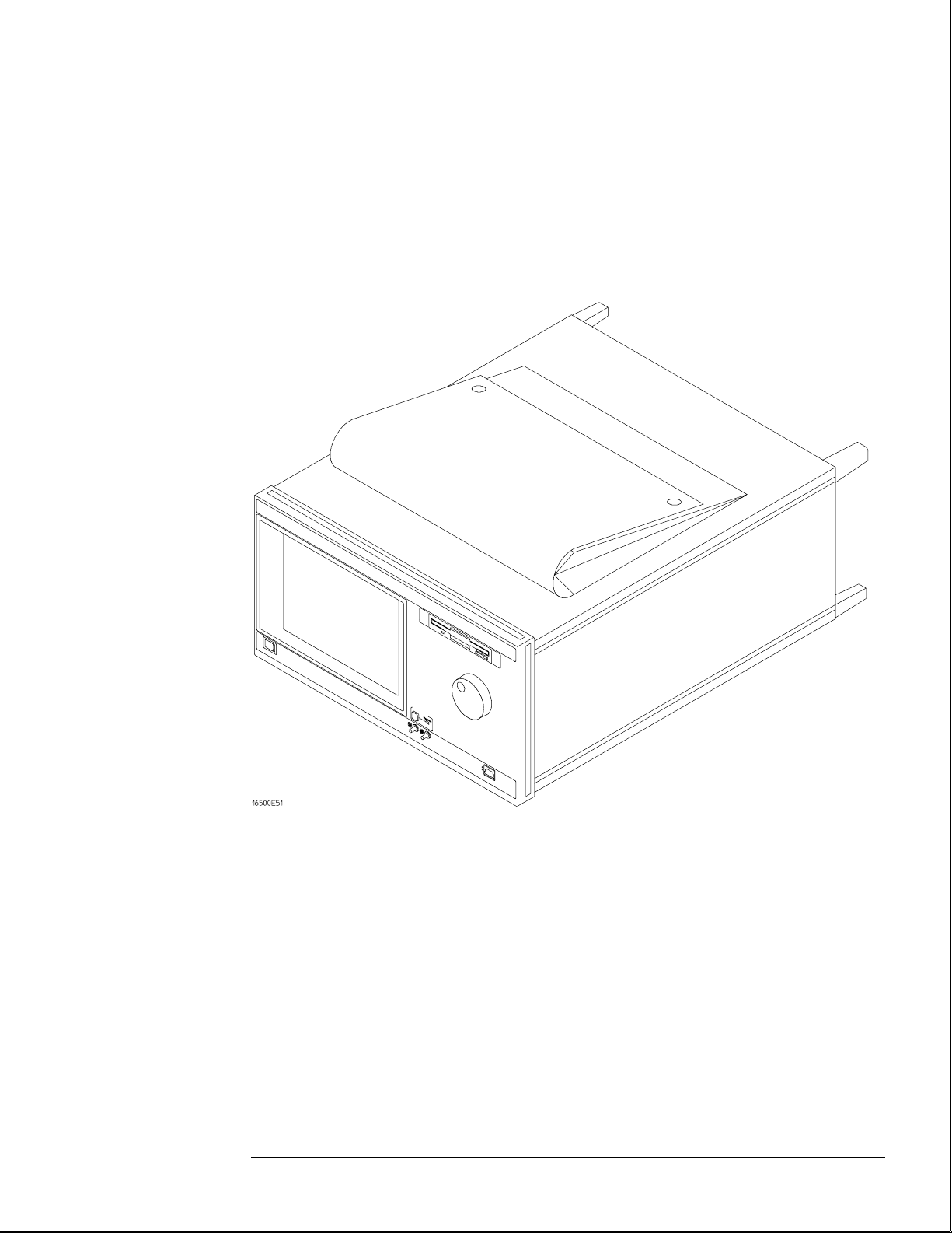
HP 16500B/16501A Logic Analysis System
The HP 16500B is the mainframe of the Logic Analysis System, and the HP 16501A is
the expansion frame. The HP 16500B/16501A is of modular structure using plug-in
cards with a wide range of data acquisition and stimulus capabilities.
Features
Some of the main features of the HP 16500B/16501A are as follows:
• Modular mainframe with five card slots
• Expansion frame, which expands the total system card slots to ten
• Touchscreen user interface
• 86 Mbyte hard disk drive
• High-density 3.5-inch flexible disk drive
• Color monitor
• Intermodule triggering and time correlation of acquired data
• HP-IB, RS-232C or optional LAN interfaces for hardcopy output to a printer or
controller interface
Service Strategy
The service strategy for this instrument is the replacement of defective assemblies.
This service guide contains information for finding a defective assembly by testing
and servicing the HP 16500B/16501A.
This instrument can be returned to Hewlett-Packard for all service work, including
troubleshooting. Contact your nearest Hewlett-Packard Sales Office for more details.
ii
Page 4
The HP 16500B Logic Analysis System
iii
Page 5

In This Book
This book is the service guide for the HP 16500B/16501A Logic Analysis System and is divided
into eight chapters.
Chapter 1 contains information about the instrument and includes accessories for the
instrument, specifications and characteristics of the instrument, and a list of the equipment
required for servicing the instrument.
Chapter 2 tells how to prepare the instrument for use.
Chapter 3 gives instructions on how to test the performance of the instrument.
Chapter 4 contains calibration instructions for the instrument.
Chapter 5 contains self-tests and flowcharts for troubleshooting the instrument.
Chapter 6 tells how to replace the instrument and assemblies of the instrument, and how to
return them to Hewlett-Packard.
Chapter 7 lists replaceable parts, shows an exploded view, and gives ordering information.
Chapter 8 explains how the instrument works and what the self-tests are checking.
This book also contains information about the HP 16500L interface module when using an
expansion frame or an external monitor. For information about using the interface module
with a local area network, refer to the manuals for the HP 16500L.
iv
Page 6
Contents
1 General Information
Accessories 1–2
Specifications 1–3
Characteristics 1–3
Recommended Test Equipment 1–6
2 Preparing for Use
To inspect the logic analysis system 2–2
To apply power 2–3
To operate the user interface 2–3
To set the line voltage 2–4
To degauss the display 2–5
To clean the logic analysis system 2–5
To test the logic analysis system 2–5
To install modules 2–6
To install the HP 16500L interface module 2–7
To connect the HP 16501A Expansion Frame 2–9
To connect an external monitor 2–10
3 Testing Performance
To perform the power-up tests 3–3
To perform the self-tests 3–4
4 Calibrating and Adjusting
To prepare the instrument 4–3
To access the test patterns 4–4
To adjust geometry 4–5
To adjust focus, landing, and convergence 4–6
To adjust white balance 4–13
5 Troubleshooting
To use the flowcharts 5–2
To check the power-up self-tests 5–18
To run the self-tests 5–19
To check the video signals 5–22
To check the power supply LEDs 5–23
To check the power supply voltages 5–24
To test the flexible disk drive voltages 5–25
To test the hard disk drive voltages 5–27
To test the expansion frame interface 5–29
v
Page 7

Contents
6 Replacing Assemblies
To remove and replace the
Optional modules or filler panels 6–3
Covers 6–4
Flexible disk drive 6–5
Power supply 6–6
Rear fan 6–8
Side fan 6–9
HP 16500L interface module 6–10
Hard disk drive 6–12
Microprocessor board (CPU) 6–13
SIMM memory 6–14
Expansion interface board 6–15
Mother board 6–16
Front-panel board 6–18
Color display assembly 6–19
To return assemblies 6–22
7 Replaceable Parts
Replaceable Parts Ordering 7–2
Replaceable Parts List Description 7–3
HP 16500B Exploded View and Replaceable Parts 7–4
HP 16501A Exploded View and Replaceable Parts 7–9
8 Theory of Operation
Block-Level Theory 8–3
The HP 16500B Logic Analysis System 8–3
The Microprocessor Board 8–6
The Power-Up Routine 8–9
The Power-Up Screen 8–9
Power-Up Self-Tests 8–10
Power-Up Tasks 8–10
The System Configuration Menu 8–12
Self-Tests Description 8–13
Power-Up Self-Tests 8–13
Functional Performance Verification Tests 8–15
HP-IB 8–18
RS-232C 8–19
vi
Page 8

1
Accessories 1–2
Specifications 1–3
Characteristics 1–3
Recommended Test Equipment 1–6
General Information
Page 9

General Information
This chapter lists the accessories, the specifications and characteristics, and the
recommended test equipment.
Accessories
The following accessories are supplied with the HP 16500B/16501A Logic Analysis System.
Accessories Supplied Qty
Training Kit 1
Setting Up The System Guide 1
User’s Reference 1
Programming Reference 1
Service Guide 1
RS-232C Loopback Connector 1
Power cord 1
Disk pouch containing backup composite software 1
Feeling Comfortable With Logic Analyzers
Feeling Comfortable with Digitizing Oscilloscopes
Filler Panels Quantity depends on how many modules are
1
1
ordered wi th the HP 16500B/16501A
Accessories Available
Other accessories available for the HP 16500B/16501A Logic Analysis System are listed in the
Accessories for HP Logic Analyzers brochure.
1–2
Page 10

General Information
Specifications
The specifications are the performance standards against which the product is tested. There
are no specifications for the HP 16500B or the HP 16501A.
Characteristics
These characteristics are not specifications, but are included as additional information. The
following characteristics are typical for the HP 16500B/16501A system.
Hard Disk Drive Capacity 86 Mbyte unformatted; Formatted as a Microsoft DOS disk drive IDE Interface
Bus.
Flexible Disk Drive Capacity 1.44 Mbyte formatted Microsoft DOS or LIF supported.
Specifications
Programmability Instrument settings and operating modes, including automatic measurements, may be
remotely programmed via RS-232C, HP-IB (IEEE-488), or optional HP 16500L (Ethernet).
Hardcopy Output Printers Supported HP ThinkJet, HP QuietJet, HP LaserJet, HP PaintJet, HP Deskjet,
HP Deskjet C, Epson and Epson-compatible (for example, Epson FX-80) via RS-232C or
HP-IB.
RS-232C Configurations Protocols: XON/XOFF, Hardware; Data bits: 8; Stop bits: 1, 1
1/2, 2; Parity: none, odd, or even; Baud rates: 110, 300, 600, 1200, 2400, 4800, 9600, 19200.
HP-IB Interface Functions SH1, AH1, T5, TE0, L3, LE0, SR1, RL1, PP1, DC1, DT1, C0
and E2.
Input/Output
Rear Panel BNCs:
Intermodule Bus (IMB)
Characteristics
Port-in
1.5 mA to +6 V at 1.6 mA.
Port-out
into 50 Ω.
Run Control Oscilloscope, timing, state, and pattern generation can be armed by Group
Run. Modules can run concurrently or be armed in series. Each module can arm one or
more modules.
Mixed Display Mode Any timing or oscilloscope waveform displays can be mixed.
State listings can be included with waveforms in the State/Timing Mixed Mode display.
User selectable: TTL, ECL or user defined; Zin = 4 kΩ ; Maximum Vin = -6.0 V at
Output signal is active high, TTL output level, high > 2 V into 50 Ω, low < 0.4 V
Acquiring Data for Mixed Displays To obtain a mixed display, multiple modules must
be armed through the IMB. To include state listings in mixed mode displays, state time
tagging must be on.
1–3
Page 11

General Information
Characteristics
Time Interval Accuracy Between Modules Equals the sum of the channel-to-channel
time interval accuracies of each module used in the measurement, for a deskewed
measurement.
Time Correlation Resolution 2 ns (500 MHz).
Operating
Environment
Weight HP 16500B
Temperature
Instrument
Disk Media
Probes and Cables
Humidity
Instrument
Disk media and hard drive
Altitude Up to 4600 m (15 000 ft). Hard drive to 300 m (10,000 ft.).
Vibration
Operating Random vibration 5-500Hz, 10 minutes per axis, ~ 2.41 g (rms).
Non-operating Random vibration 5-500Hz, 10 minutes per axis, ~ 2.4 g (rms); and
swept sine resonant search, 5-500Hz, 0.75g (0-peak), 5 minute dwell at 4 resonances
per axis.
Net 18.1 kg (40 lbs) + [0.7 kg (1.6 lbs) x number of optional cards installed].
Shipping 25.9 kg (57 lbs) + [3.6 kg (8 lbs) x number of optional cards installed].
HP 16501A
Net 12.2 kg (27 lbs) + [0.7 kg (1.6 lbs) x number of optional cards installed].
Shipping 19.9 kg (44 lbs) + [3.6 kg (8 lbs) x number of optional cards installed].
0 °C to 50 °C (+32 °F to 122 °F).
10 °C to 40 °C (+50 °F to 104 °F).
0 °C to 65 °C (+32 °F to 149 °F).
up to 95% relative humidity at 40 °C (104 °F).
8% to 80% relative humidity at 40 °C (104 °F).
Power Requirements HP 16500B 115 V/230 V, -22% to +10%, 48 to 66 Hz, 475 W max.
HP 16501A 115 V/230 V, -22% to +10%, 48 to 66 Hz, 420 W max.
1–4
Page 12
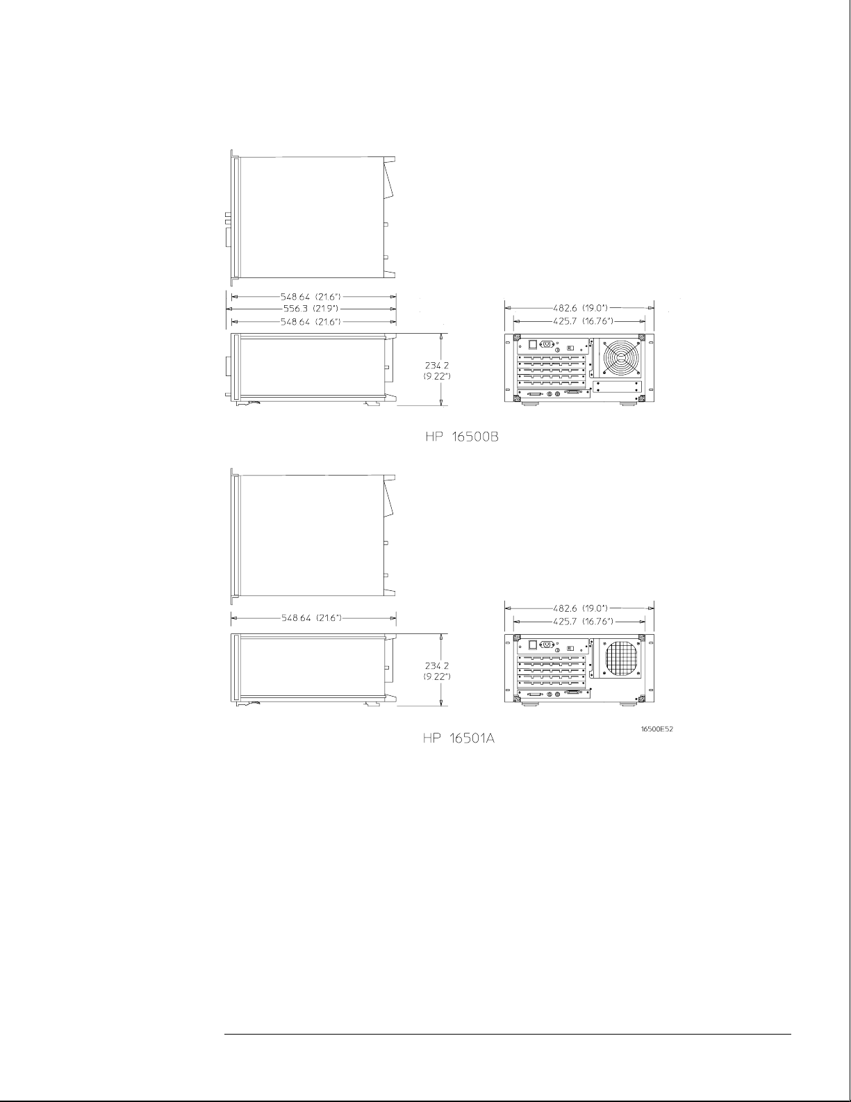
Dimensions Refer to the following figure for dimensional detail.
General Information
Characteristics
Dimensional Detail
1–5
Page 13

General Information
Recommended Test Equipment
Recommended Test Equipment
Equipment Required
Equipment Critical Specifications Recommended
Model/Part
Oscilloscope 100 MHz Bandwidth HP 54600A T
Voltmeter HP 3478A T
RS-232C Loopback
Connector
*A = Adjustment P = Performance Tests T = Troubleshooting
HP Part Number
01650-63202
Use
T
*
1–6
Page 14
2
To inspect the logic analysis system 2–2
To apply power 2–3
To operate the user interface 2–3
To set the line voltage 2–4
To degauss the display 2–5
To clean the logic analysis system 2–5
To test the logic analysis system 2–5
To install modules 2–6
To install the HP 16500L interface module 2–7
To connect the HP 16501A Expansion Frame 2–9
To connect an external monitor 2–10
Preparing for Use
Page 15

Preparing For Use
This chapter gives you instructions for preparing the logic analysis system for use.
Power Requirements
The logic analysis system mainframe requires a power source of either 115 Vac or 230
Vac, –22 % to +10 %, single phase, 48 to 66 Hz, 475 W maximum power.
The logic analysis system expansion frame requires a power source of either 115 Vac
or 230 Vac, –22 % to +10 %, single phase, 48 to 66 Hz, 420 W maximum power.
Operating Environment
The operating environment is listed in chapter 1. Note the noncondensing humidity
limitation. Condensation within the instrument can cause poor operation or
malfunction. Provide protection against internal condensation.
The logic analysis system will operate at all specifications within the temperature and
humidity range given in chapter 1. However, reliability is enhanced when operating it
within the following ranges:
WARNING
• Temperature: +20 °C to +35 °C (+68 °F to +95 °F)
• Humidity: 20% to 80% noncondensing
Storage
Store or ship the logic analysis system in environments within the following limits:
• Temperature: -40 °C to + 75 °C
• Humidity: Up to 90% at 65 °C
• Altitude: Up to 15,300 meters (50,000 feet)
Protect the system from temperature extremes which cause condensation on the
instrument.
To inspect the logic analysis system
1 Inspect the shipping container for damage.
If the shipping container or cushioning material is damaged, keep them until you have
checked the contents of the shipment and checked the instrument mechanically and
electrically.
Hazardous voltages exist in this instrument. To avoid electrical shock, do not apply power to
a damaged instrument.
2–2
Page 16

2 Check the supplied accessories.
Accessories supplied with the logic analysis system are listed in "Accessories" in chapter 1.
3 Inspect the product for physical damage.
Check the logic analysis system and the supplied accessories for obvious physical or
mechanical defects. If you find any defects, contact your nearest Hewlett-Packard Sales
Office. Arrangements for repair or replacement are made, at Hewlett-Packard’s option,
without waiting for a claim settlement.
To apply power
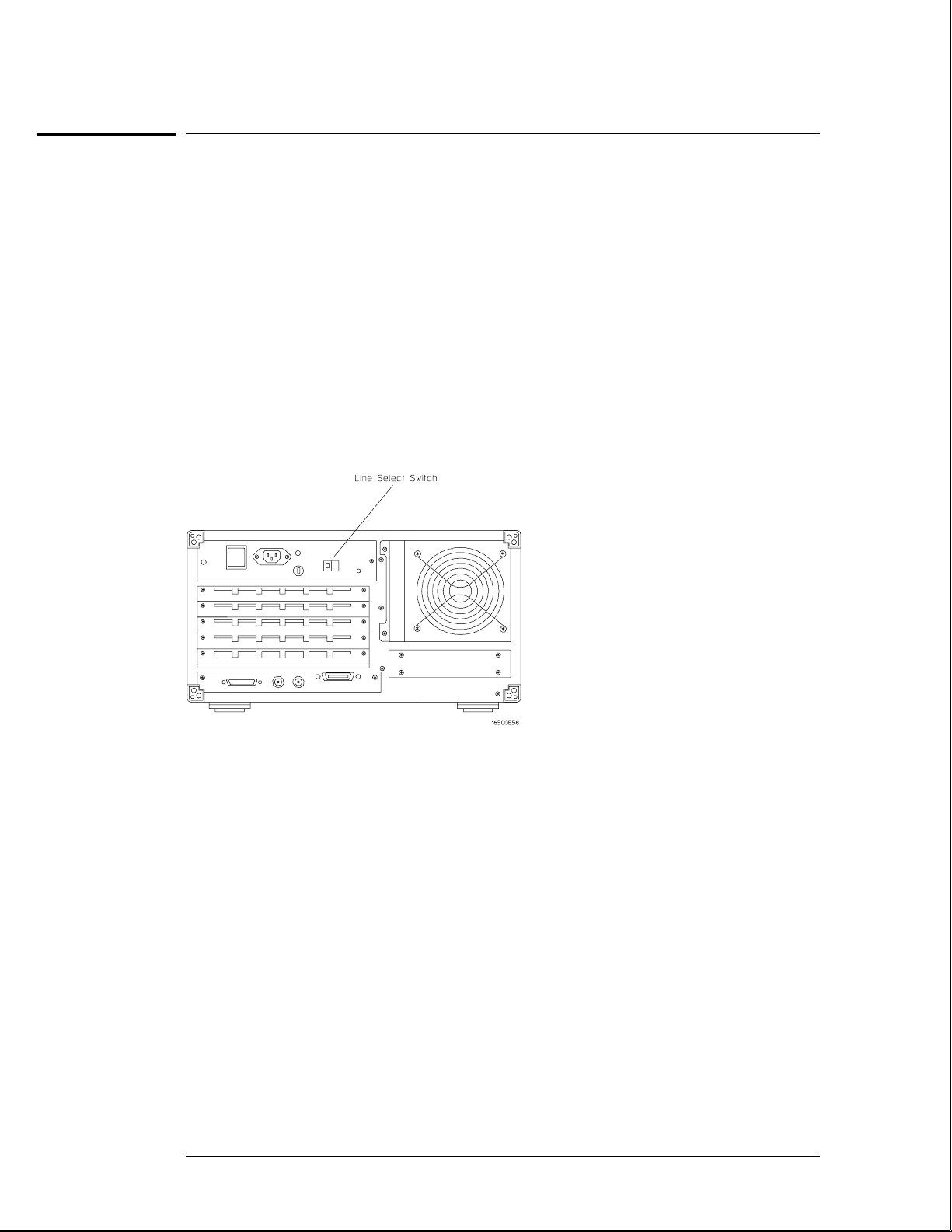
1 Check that the line voltage selector, located on the rear panel, is on the correct
setting and the correct fuse is installed.
See also, "To set the line voltage" in this chapter.
2 Connect the power cord to the instrument and to the power source.
This instrument is equipped with a three-wire power cable. When connected to an
appropriate ac power outlet, this cable grounds the instrument cabinet. The type of power
cable plug shipped with the instrument depends on the country of destination. Refer to
chapter 7, "Replaceable Parts," for option numbers of available power cables.
Turn on the instrument line switch located on the rear panel, then turn on the power
3
standby switch located on the front panel.
Preparing for Use
To apply power
To operate the user interface
• To select a field on the mainframe screen, use the touchscreen.
For more information about the logic analysis system interface, refer to the
HP 16500B/16501A Logic Analysis System User’s Reference.
• To set the HP-IB address or to configure for RS-232C, refer to the
HP 16500B/16501A Logic Analysis System User’s Reference.
2–3
Page 17
Preparing for Use
To set the line voltage
To set the line voltage
When shipped from HP, the line voltage selector is set and an appropriate fuse is installed for
operating the instrument in the country of destination. To operate the instrument from a
power source other than the one set, perform the following steps.
Turn the front panel power switch to the STBY position, then turn the power switch
1
to the Off position. Remove the power cord from the instrument.
2 Replace the main fuse with a 5 A/250 V fuse for 230 V operation, or a 10 A/125 V fuse
for 115 V operation.
3 Set the rear panel line select switch for the desired voltage.
4 Reconnect the power cord, turn on the rear panel power switch, then continue
normal operation.
5 If your system includes an HP 16501A Expansion Frame, repeat this procedure for it.
The expansion frame has only one power switch, and that switch is located on the rear panel.
Line Voltage Selection
2–4
Page 18

Preparing for Use
To degauss the display
To degauss the display
• If the mainframe has been subjected to strong magnetic fields, the CRT might
become magnetized and display data might become distorted. To correct this
condition, degauss the CRT with a conventional, external-television-type degaussing
coil.
To clean the logic analysis system
• With the instrument turned off and unplugged, use mild soap and water to clean the
front and cabinet of the system. Harsh soap might damage the water-base paint.
To test the logic analysis system
The logic analysis system does not require calibration or adjustment.
• If you require a test to initially accept the operation, perform the self-tests in
chapter 3, "Testing Performance."
• If the logic analysis system does not operate correctly, go to the beginning of
chapter 5, "Troubleshooting."
2–5
Page 19

CAUTION
Preparing for Use
To install modules
To install modules
The following steps give general instructions for installing modules into the mainframe or the
expansion frame of the system.
Electrostatic discharge can damage electronic components. Use grounded wriststraps and
mats when performing any service to modules.
1
Turn off the frame power switch, then unplug the power cord. Disconnect any input
or output connections.
2 Plan your module configuration.
Refer to the manuals of individual modules for configuration information.
Loosen the thumb screws.
3
Cards or filler panels below the slots intended for installation do not have to be removed.
Starting from the top, loosen the thumb screws on filler panels and cards that need to be
moved.
Starting from the top, pull the cards and filler panels that need to be moved halfway
4
out.
All multicard modules will be cabled together. To prevent damage to the cables and
connectors, pull these cards out together.
Remove the cards and filler panels.
5
Remove the cards or filler panels that are in the slots intended for the module installation.
Some modules for the logic analysis system require calibration if you move them to a different
slot. Refer to the manuals of individual modules for calibration information.
6
Install the module.
You may need to push all other cards into the card cage, but not completely in, to get them
out of the way for installing the module.
Refer to the manuals of individual modules for cabling information.
Slide the complete module into the frame, but not completely in.
7
Each card is firmly seated and tightened one at a time in step 9.
8 Position all cards and filler panels so that the endplates overlap.
9 Seat the cards and tighten the thumbscrews.
Starting with the bottom card, firmly seat the cards into the backplane connector of the
mainframe. Keep applying pressure to the center of the card endplate while tightening the
thumbscrews finger-tight. Repeat this for all cards and filler panels starting at the bottom and
moving to the top.
CAUTION
See Also Service Guides for the individual modules.
For correct air circulation, filler panels must be installed in all unused card slots. Correct air
circulation keeps the instrument from overheating. Keep any extra filler panels for future use.
10
Plug in the system, then turn it on.
When you turn on the power switch, the logic analysis system performs power-up tests. After
the power-up tests are complete, the screen will show your system configuration.
2–6
Page 20
WARNING
CAUTION
Preparing for Use
To install the HP 16500L interface module
To install the HP 16500L interface module
The HP 16500L interface module is required to connect the HP 16501A Expansion Frame to
the HP 16500B mainframe.
Hazardous voltages exist on the power supply, the CRT, and the CRT driver board of the
HP 16500B mainframe. To avoid electrical shock, disconnect the power from the instrument
before performing the following procedures. After disconnecting the power, wait at least six
minutes for the capacitors on the power supply board and the CRT driver board to discharge
before servicing the instrument. However, if the AC LED on the power supply has any
illumination, a significant charge remains on the power supply capacitors.
Electrostatic discharge can damage electronic components. Use grounded wriststraps and
mats when performing any service to this module or to the HP 16500B Logic Analysis System.
For correct orientation of the cables, match the slots on the cable connectors and on the
board connectors.
Remove power from the HP 16500B mainframe, then remove the optional modules,
1
the four rear feet, and the top and bottom covers of the mainframe.
2 Remove the sheetmetal plate on the rear of the mainframe covering the slot where
the HP 16500L interface module will be installed.
With the interface module installed, you will not use the plate. Save the plate to use in case
the interface module is removed.
Remove the cable connecting the CRT module to the CPU board.
3
To release the cable, push the tabs on the board connector to the outside of the connector.
With the interface module installed, you will not use this cable. Save the cable to use in case
the interface module is removed.
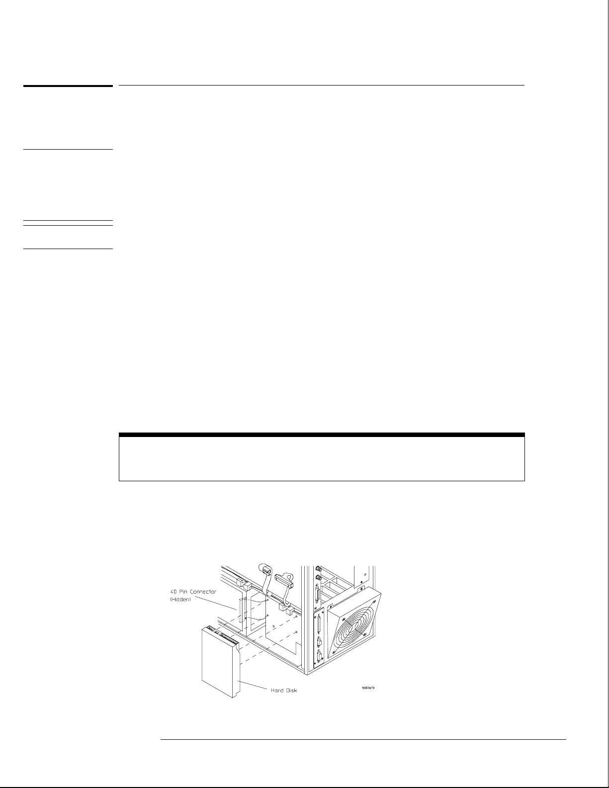
If you need more room to replace the CRT cable, you can remove the hard disk drive. Removing
the hard disk is not necessary, but gives you more room for replacing the CRT cable. The hard
disk is connected with four screws.
4
Connect one end of the new 40-pin cable to the CRT module.
Push the cable connector into the board connector until the tabs lock in the cable.
If you removed the hard disk drive, replace it before going to the next step.
2–7
Page 21
Preparing for Use
To install the HP 16500L interface module
5 Slide the interface module into the mainframe through the slot in the rear panel.
6 Install the screws connecting the interface module to the mainframe.
Two screws through the top of the interface module connect it to the sheetmetal plate, and
four screws through the rear plate of the interface module connect it to the rear panel of the
mainframe.
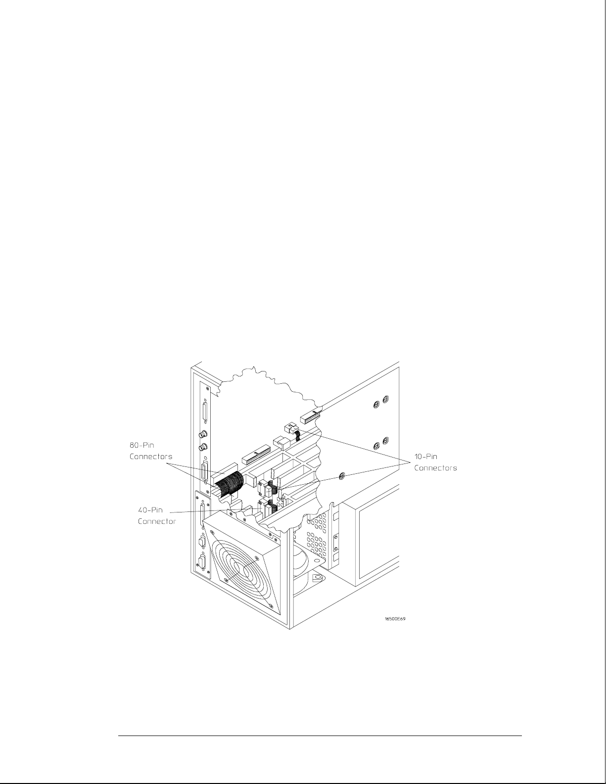
Connect the end of the 40-pin CRT cable to the interface module.
7
8 Connect the 80-pin cable to the CPU board and to the interface module.
a Slide the 80-pin cable halfway through the rear slot of the card cage between the
interface module and the CPU board.
b Connect the cable to the CPU board.
c Connect the cable to the interface module.
Connect the 10-pin cable to the CPU board and to the interface module.
9
10 Replace the top and bottom covers, the optional modules, and the rear feet of the
mainframe.
11 Turn on the system.
a Connect a power cord to the frame.
b Turn on the line switch located on the rear panel the frame.
c Turn on the power standby switch located on the front panel of the mainframe.
When the power-up tests are complete, the mainframe screen shows "Ethernet" in the
Communications menu.
2–8
Page 22
CAUTION
Preparing for Use
To connect the HP 16501A Expansion Frame
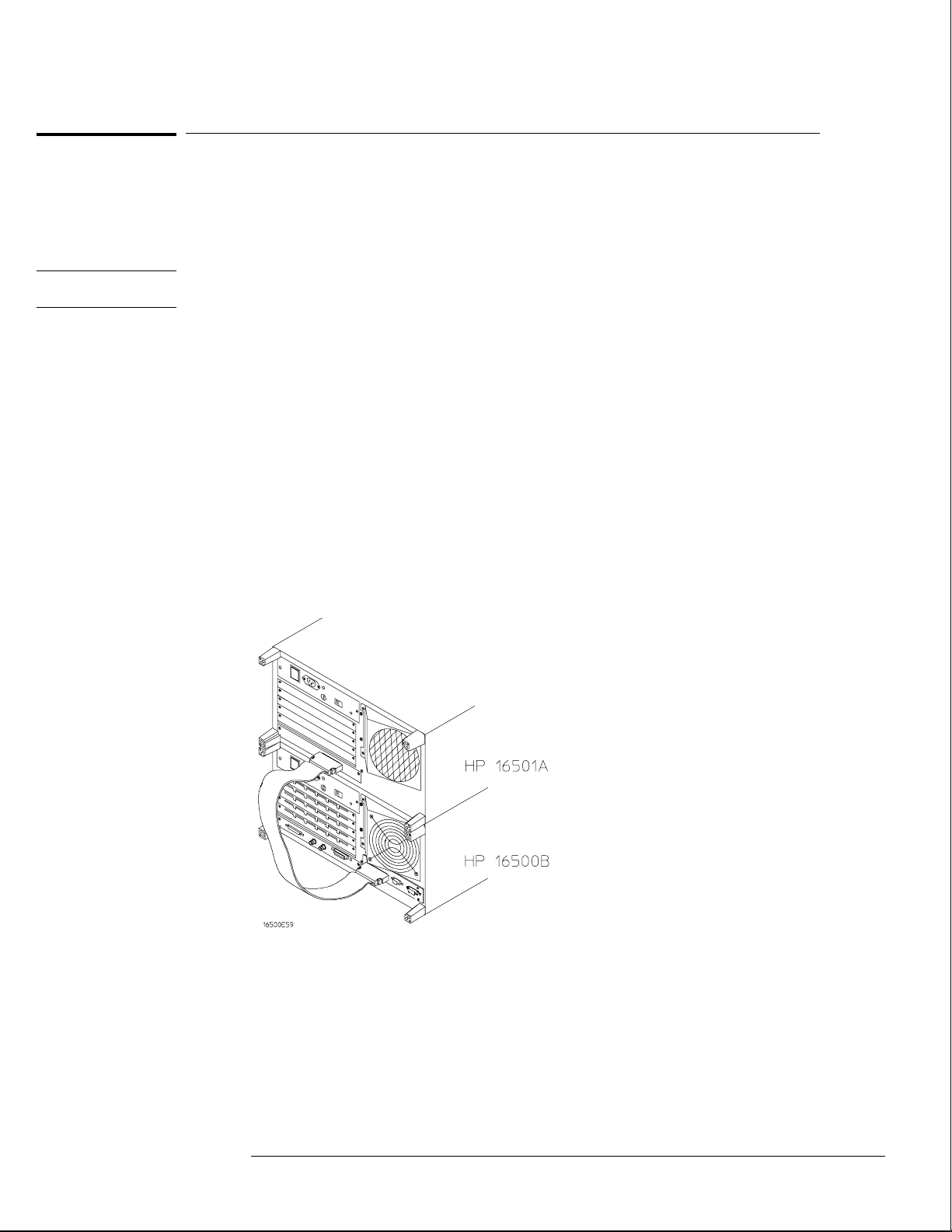
To connect the HP 16501A Expansion Frame
The HP 16501A Expansion Frame includes an interface cable and requires an HP 16500L
interface module to connect to the HP 16500B mainframe. To install the expansion frame,
you need to install the interface module into the mainframe, then connect the cable from the
module to the expansion frame.
Electrostatic discharge can damage electronic components. Use grounded wriststraps and
mats when performing any service to this card.
1
Turn off the mainframe power switch, then unplug the power cord. Disconnect any
input connections.
2 Verify that the line select switch located on the rear panel of the expansion frame is
in the off position.
3 Install the HP 16500L interface module into the mainframe.
The procedure for installing the HP 16500L is on page 2–7.
4 Connect the interface cable to the expansion frame and to the interface module in
the mainframe.
To ensure correct insertion, the 68-pin "D" connectors on each end of the interface cable are
asymmetric in shape. They only fit into their respective ports on the cards when oriented to
match the shape of the ports.
When connecting the interface cable, you will hear two clicks. Make sure the cable connector
is properly seated into the port by pulling the connector without pressing the release tabs. If
the connector is properly seated, it will remain connected to the port.
Turn on the system.
5
a Connect a power cord to each frame.
b Turn on the line switch located on the rear panel of each frame.
c Turn on the power standby switch located on the front panel of the mainframe.
When the power-up tests are complete, the mainframe screen shows "Master
Frame" in a blue field.
2–9
Page 23
Preparing for Use
To connect an external monitor
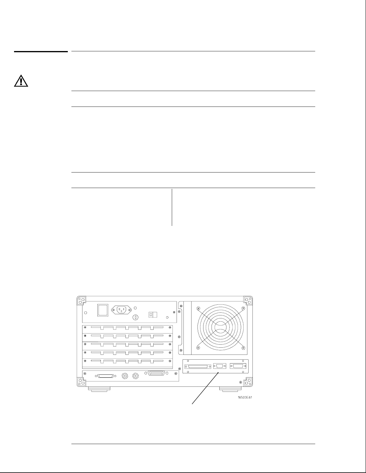
To connect an external monitor
The following tables define the signal available for external monitors at the HP 16500L
connector and pin numbers.
HP 16500L Output Signal For External Monitors
Horizontal deflection (fh) 25.0 kHz
Vertical deflection (fv) 59.95 Hz
Resolution 576 x 368 x dots x lines (WxH)
RGB video 0.714 VP-P, positive
Impedance 75 ohm , analog
External Sync Signal
Connector Pins
H TTL, negative 3.2 µS;
W TTL, negative, 120 µS
Pin number Signal Pin number Signal
1 Red 6,7,8,10 Ground
2 Green 13 Horizontal Sync
3 Blue 14 Vertical Sync
1 Connect your monitor to the HP 16500L interface module installed into the
HP 16500B mainframe.
2 If your monitor needs adjusting, follow the manufacturer’s instructions.
2–10
Connector for
external monitor
Page 24

3
To perform the power-up tests 3–3
To perform the self-tests 3–4
Testing Performance
Page 25

Testing Performance
To ensure the logic analysis system is operating correctly, you can perform software
tests (self-tests) on the system. Directions for performing the software tests are
given in this chapter.
This chapter normally tells you how to test the performance of the logic analysis
system against the specifications listed in chapter 1. Because there are no
specifications for the HP 16500B/16501A, there are no performance verification tests.
Self-Tests
The self-tests listed in this chapter check the functional operation of the mainframe
and the expansion frame. Self-tests for the optional modules installed in the frames
are listed in the individual module Service Guides.
There are two types of self-tests: self-tests that automatically run at power-up, and
self-tests that you select on the screen. For descriptions of the tests, refer to chapter
8, "Theory of Operation."
Perform the self-tests as an acceptance test when receiving the logic analysis system
or when the logic analysis system is repaired.
If a test fails, refer to chapter 5, "Troubleshooting."
Test Interval
There is no recommended test interval for the HP 16500B mainframe or the
HP 16501A expansion frame. However, each of the HP 16500-series option modules
has performance verification tests and therefore require a periodic verification of
specifications. Refer to the Service Guides of the individual modules for more
information.
The Logic Analysis System Interface
To select a field on the HP 16500B screen, use the touchscreen. For more
information about the logic analysis system interface, refer to the
HP 16500B/16501A Logic Analysis System User’s Reference.
3–2
Page 26

Testing Performance
To perform the power-up tests
To perform the power-up tests
The logic analysis system automatically performs power-up tests when you apply power to the
instrument. The revision number of the boot ROM shows in the upper-right corner of the
screen during these power-up tests. As each test completes, either "passed" or "failed" prints
on the screen in front of the name of each test.
Disconnect all inputs, then insert a formatted disk into the flexible disk drive.
1
2 Let the instrument warm up for a few minutes, then cycle power by turning off then
turning on the power switch.
If the instrument is not warmed up, the power-up test screen will complete before you can
view the screen.
As the tests complete, check if they pass or fail.
3
The Flexible Disk Test reports No Disk if a disk is not in the disk drive.
If a power-up self-test fails, refer to chapter 5, "Troubleshooting."
Performing Power-Up Self-Tests
passed ROM Test
passed RAM Test
passed Interrupt Test
passed Display Test
passed HIL Controller Test
passed Front-Panel Test
passed Touchscreen Test
passed Correlator Test
passed Hard Disk Test
passed Flexible Disk Test
Loading Module Files
3–3
Page 27
Testing Performance
To perform the self-tests
To perform the self-tests
The self-tests verify the correct operation of the logic analysis system. Self-tests can
be performed all at once or one at a time. While testing the performance of the logic
analysis system, run the self-tests all at once.
1 If you just did the power-up self-tests, go to step 2.
If you did not just do the power-up self-tests, disconnect all inputs, then turn on the
power switch. Wait until the power-up tests are complete.
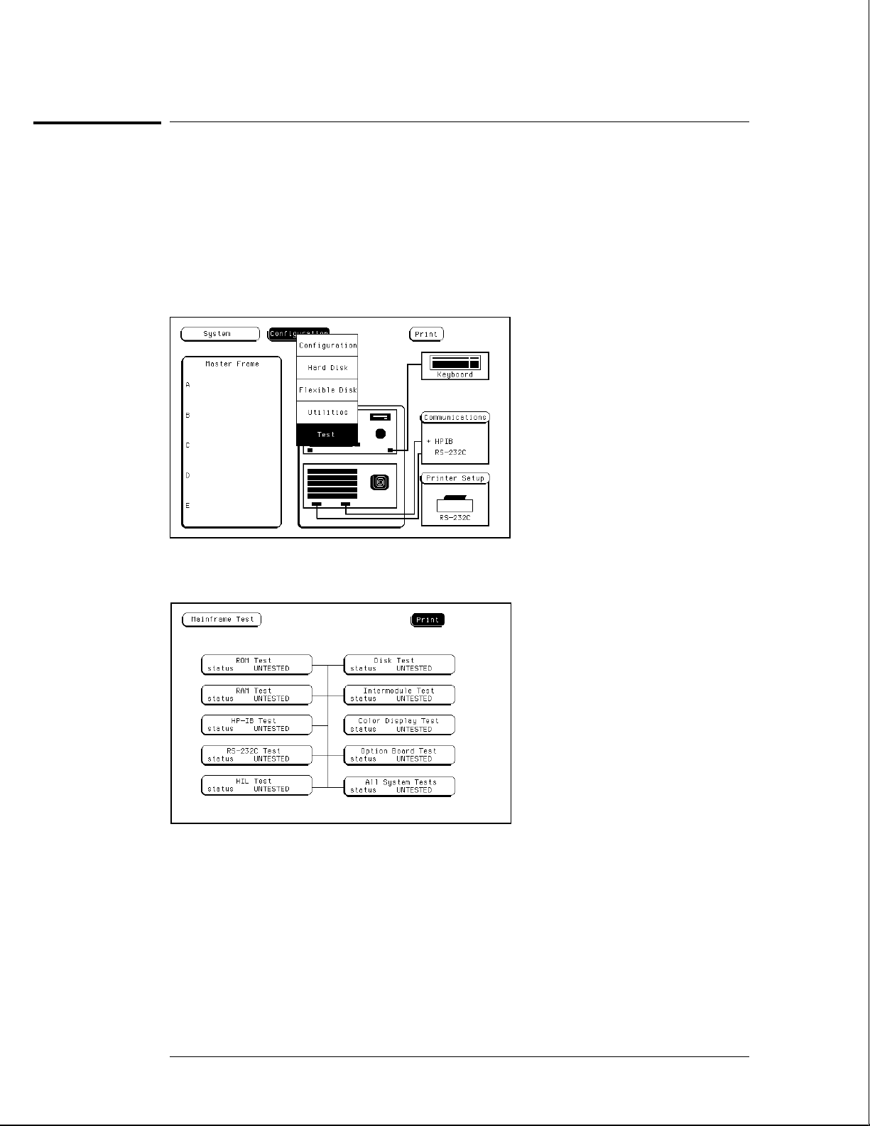
2 In the System Configuration menu, select Configuration, then select Test.
3 Select the box labeled Load Test System.
4 Select Test System, then select Mainframe Test from the pop-up menu.
3–4
Page 28
Testing Performance
To perform the self-tests
5 Install a formatted disk that is not write protected into the flexible disk drive.
Connect an RS-232C loopback connector onto the RS-232C port.
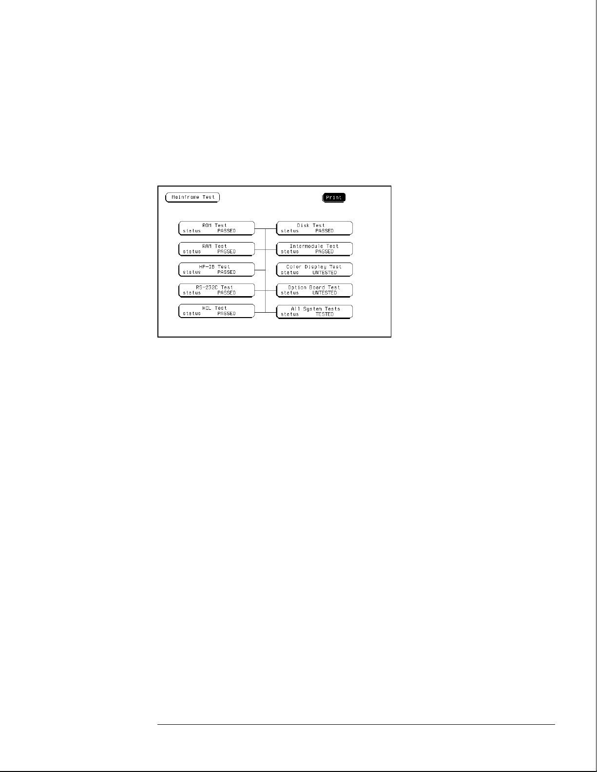
6 Select All System Tests.
You can run all tests at one time by running All System Tests. To see more details about each
test, you can run each test individually. This step shows how to run all tests at once.
The status of the tests will change from Untested to Passed or Failed. If a test fails, refer to
chapter 5, "Troubleshooting."
The Color Display Test is not normally needed. The screens are primarily used when the
color display assembly requires adjusting. For the adjustment procedure, refer to chapter 4,
"Calibrating and Adjusting."
Exit the mainframe tests.
7
a In the Mainframe Test menu, select Mainframe Test, then select Test System.
b Select Configuration, then select Exit Test in the pop-up menu.
c Select the field close to the center of the screen to exit the test system and to load the
mainframe operating system.
After the operating system is loaded, the System Configuration menu is displayed.
3–5
Page 29

3–6
Page 30

4
To prepare the instrument 4–3
To access the test patterns 4–4
To adjust geometry 4–5
To adjust focus, landing, and convergence 4–6
To adjust white balance 4–13
Calibrating and Adjusting
Page 31

Calibrating and Adjusting
This chapter normally gives you instructions for calibrating and adjusting the logic
analysis system. Because the HP 16500B/16501A requires no calibration, only
adjustment instructions are included.
Adjustments
The only adjustments to the logic analysis system are adjustments to the color CRT
monitor assembly.
Use the following procedures to adjust the CRT module to compensate for magnetic
influences causing misconvergence.
WARNING
Hazard voltages exist on the power supply, the CRT, and the CRT driver board. To avoid
electrical shock, read and follow the Safety and Warning considerations at the end of this
manual before performing adjustment procedures.
Adjustment Interval
DO NOT PERFORM THESE ADJUSTMENTS AS A PART OF ROUTINE
CALIBRATIONS. The following procedures are provided only for the few extreme
cases where either the earth’s magnetic field or the user’s environment cause an
unusable display due to misconvergence that cannot be corrected by degaussing the
entire CRT screen.
DO NOT perform the procedures in this chapter before first degaussing the CRT
screen using the rear-panel degaussing switch. In extreme cases of magnetism, it
may be necessary to degauss the CRT using a conventional external television-type
degaussing coil.
Adjustment Personnel
It is recommended that these adjustments be performed only by qualified personnel
who are familiar with color CRT convergence procedures.
Equipment Required
The instrument firmware supplies the display patterns necessary for adjustment.
The only tool required is a nonmetallic adjustment tool:
• Sony Part Number 4-367-065-01
• HP Part Number 8710-1355
4–2
Page 32

Calibrating and Adjusting
To prepare the instrument
To prepare the instrument
1 Remove the rear feet and the covers from the mainframe.
2 Before starting the adjustments, mark the position where the potentiometers are set.
This helps in returning the adjustments to their original positions if it becomes necessary to
restart the procedure.
During any of the following CRT adjustments, the CRT module must face west.
3
4 Use the following chart to guide you with the CRT adjustment procedure.
The following CRT adjustments are broken down into adjustment groups. The adjustment
group sequence must be followed in order because of interaction and dependency. The
adjustment group sequence is shown in the adjustment flow diagram below. There will be
cases where not all of the adjustments groups will be used. For example, if the Geometry
Adjustment Group corrects the problem, this will be the only group used.
Colo
r
CRT
Mod
ule
Adju
stme
nt
Flow
Diag
ram
4–3
Page 33

Calibrating and Adjusting
To access the test patterns
To access the test patterns
Some procedures on the following pages ask you to access test patterns. This procedure tells
you how to access them and how to exit the test.
In the System Configuration menu, touch Configuration, then select Test in the
1
pop-up menu.
2 Touch the field near the center of the screen to load the Test System.
3 In the Test System Configuration menu, touch Test System, then select Mainframe
Test in the pop-up menu.
The screen displays the Mainframe Test menu.
4 Touch the Color Display Test field to display the first test pattern, which is the
white, cross-hatch pattern.
5 Touch Continue to see the next test pattern.
With every touch of the Continue field, the next test pattern will be displayed. When
Continue is selected from the black raster pattern, the Mainframe Test menu will be displayed.
Notice that the status of the Display field changes to Tested.
To exit the test system, touch the Mainframe Test field, then touch the Test System.
6
Touch Configuration, select test, then touch the field near the center of the screen to
exit the test system.
4–4
Page 34

Calibrating and Adjusting
To adjust geometry
To adjust geometry
1 Display the white cross-hatch test pattern on the CRT.
From the Color Display Test menu, select the white, cross-hatch pattern.
2 Preset the front panel brightness control, the top of the two controls to the left of
the display, maximum clockwise.
3 Preset the front panel contrast control, the bottom of the two controls to the left of
the display, to the mechanical center.
4 Preset H.SUB SHIFT (RV006) and V.SUB SHIFT (RV008), located on the bottom PC
board, to the mechanical centers.
All of the following adjustment potentiometers are located on the PC board on the left side of
the display.
Adjust the display size. Measure with a flexible ruler.
5
Adjust H.SIZE (RV504) for a 161 mm (6.34 in.) width.
•
Adjust V.HEIGHT (RV50) for a 120.5 mm (4.74 in.) height.
•
Center the pattern.
6
Adjust V.CENT (RV510) for vertical centering.
•
Adjust H.CENT (RV503) for horizontal centering.
•
Adjust PIN AMP (RV506) to eliminate pincushion distortion in the vertical lines of
7
the cross-hatch pattern as shown in the next figure.
8 Remove the left, bottom rail of the mainframe.
The left, bottom rail must be removed in order to access the next adjustment.
9 Adjust PIN PHASE (RV505) to eliminate pin phase distortion in the vertical lines of
the cross-hatch pattern as shown in the next figure.
10 Reinstall the bottom rail.
11 Adjust TOP PIN (RV511) so that the top horizontal line is parallel with the center
horizontal line.
12 Adjust BOTTOM PIN (RV512) so that the bottom horizontal line is parallel with the
center horizontal line.
4–5
Page 35

Calibrating and Adjusting
To adjust focus, landing, and convergence
To adjust focus, landing, and convergence
Once you have started, you will have to do all three of the procedures in this group: the focus,
the landing, and the convergence adjustments.
Initial Preparation
Loosen the deflection yoke clamp screw.
1
2 Remove the rear and side fans.
Refer to chapter 6, "Replacing Assemblies."
Focus Adjustment
Geometry adjustments must be performed before making the focus adjustment.
Display the white, cross-hatch test pattern on the display.
1
From the Color Display Test menu, select the white, cross-hatch pattern.
2 Adjust FOCUS (RV701), located on the rear PC board, for best overall focus.
4–6
Page 36

Calibrating and Adjusting
To adjust focus, landing, and convergence
Landing Adjustment
Turn the front panel BRIGHTNESS control fully clockwise.
1
2 Degauss the CRT by momentarily pressing the DEGAUSS switch located on the
instrument rear panel.
In some cases, the user’s environment or shipping environment may have caused high levels of
magnetization in the CRT. In this case, to completely degauss the CRT you may need to use a
conventional television-type degaussing coil.
Red
Green
Blue
Set the purity magnet tabs to the mechanical center. Refer to the next figure.
3
4 Display a green raster test pattern on the display.
From the Color Display Test menu, select the green raster.
In the next steps, while moving the deflection yoke forward and rearward, rotate the yoke as
necessary to keep the edges of the raster parallel to the sides of the display.
Move the deflection yoke rearward until the left edge of the raster turns red and the
6
right side of the raster turns blue.
7 Adjust the purity magnets until green is in the center of the raster with red and blue
bands evenly distributed on the sides.
4–7
Page 37

Purity control
corrects this area
Deflection yoke
position corrects
these areas
Calibrating and Adjusting
To adjust focus, landing, and convergence
8 Move the deflection yoke forward until the entire raster is green.
Landing adjustment is easier if the yoke is moved all the way forward and then moved back
until the raster is completely green.
Using the Color Purity key, replace the green raster with red and then blue raster,
9
each time checking for proper landing adjustment (color purity of each).
10 If the landing is not correct in step 9, repeat steps 6 through 9 for the best
compromise.
11 If the landing is not correct in step 10, readjust purity magnets for best landing of
each color.
12 When the landing adjustment is complete, tighten the deflection yoke clamp screw
just enough to keep the yoke from moving. DO NOT over tighten or you might
damage the CRT.
4–8
Page 38

Calibrating and Adjusting
To adjust focus, landing, and convergence
Static Convergence
Temporarily disconnect the power from the instrument.
1
2 Remove the PC board shield cover from the rear of the Color CRT Module by prying
evenly on all four sides.
3 Reapply power.
4 Display the white, cross-hatch test pattern on the CRT.
From the Color Display Test menu, select the white, cross-hatch pattern.
5 Preset front panel brightness control, the top of the two controls to the left of the
display, maximum clockwise.
6 Preset front panel contrast control, the bottom of the two controls to the left of the
display, to the mechanical center.
7 Check the four dots which are located around the center intersection of the
cross-hatch pattern for coincidence of the blue, red, and green dots. If the dots are
not coincident, adjust H.STAT (RV703) located on the rear PC board to obtain
horizontal coincidence and V.STAT (RV803) located on the bottom PC board to
obtain vertical coincidence.
V.STAT
Center dot
H.STAT
Due to interaction, the BEAM LANDING will need to be readjusted if either the H.STAT or
V.STAT adjustments are made. Once the BEAM LANDING is re-adjusted, repeat step 7 above
if necessary to obtain the center screen coincidence of the dots.
4–9
Page 39

Calibrating and Adjusting
To adjust focus, landing, and convergence
Dynamic Convergence
Display the white, cross-hatch test pattern on the CRT.
1
From the Color Display Test menu, select the white, cross-hatch test pattern.
2 Adjust Y BOW (RV805) located on the bottom PC board to eliminate red, green, and
blue bowing at the top and bottom of the center vertical line.
3 Adjust Y CROSS (RV804) located on the bottom PC board to eliminate red, green,
and blue orthogonal misalignment at the top and bottom of the center vertical line.
4–10
Page 40

Calibrating and Adjusting
To adjust focus, landing, and convergence
4 Adjust V TOP (RV801) and V BOTTOM (RV802) to obtain coincidence of the red,
blue, and green at the intersection of the top and bottom horizontal lines with the
center vertical line. The VTOP and VBOTTOM adjustments are located on the
bottom PC board. Use the next two figures for V TOP and V BOTTOM respectively.
4–11
Page 41

Calibrating and Adjusting
To adjust focus, landing, and convergence
5 Adjust H.AMP (RV807) located on the bottom PC board for equal amounts of
misconvergence at the right and left sides of the screen.
6 Adjust H.TILT (RV806) located on the bottom PC board for coincidence of red,
green, and blue at the right and left sides of the screen.
7 If you are finished with the CRT adjustments, replace the fans.
If you need to adjust the white balance, which is the next procedure, you will
replace the fans after completing that procedure.
4–12
Page 42

Calibrating and Adjusting
To adjust white balance
To adjust white balance
1 Provide a blank display on the CRT.
From the Color Display Test menu, select a blank (colorless) raster.
2 Preset the front panel brightness and contrast controls to their mechanical centers.
3 On the bottom PC board, set the following adjustments to their mechanical centers.
SUB BRT (RV901)
•
SUB CONT (RV902)
•
4 On the bottom PC board, set the following adjustments to their mechanical centers.
G. DRIVE (RV921)
•
B. DRIVE (RV931)
•
R. DRIVE (RV911)
•
5 On the rear PC board, set the following adjustments fully counterclockwise.
G. BKG (RV721)
•
B. BKG (RV731)
•
R. BKG (RV711)
•
6 Adjust the SCREEN (RV702) located on the rear PC board until either the red, green,
or blue raster just starts to become visible. Note which color becomes visible first
and do not adjust the background control (BKG) for that color in the next step.
7 Adjust the other two background controls for the best white balance.
8 From the Color Display Test menu, select the white raster test pattern.
9 Set the front panel brightness control to maximum.
10 On the bottom PC board, adjust the DRIVE controls (RV921, RV931 and RV911) for
the best white balance.
For a white balance reference, use an average piece of white photocopy paper and compare
the white on the CRT to the paper.
Repeat steps 1-3 followed by 6-10 until satisfied with the white balance.
11
Essentially, from this point the procedure is as follows:
a With a blank screen, the front panel brightness set to center, and SCREEN (RV702) set
for minimum background, adjust the BKG controls (G.-RV721, B.-RV731, and
R.-RV711) for the best white balance.
b With a white raster and the front panel brightness set to maximum, adjust the DRIVE
controls (G.-RV921, B.-RV931, and R.-RV911) for best white balance.
c Repeat until satisfied with the white balance.
Replace the side and rear fans.
12
Refer to chapter 6, "Replacing Assemblies."
4–13
Page 43

4–14
Page 44

5
To use the flowcharts 5–2
To check the power-up self-tests 5–18
To run the self-tests 5–19
To check the video signals 5–22
To check the power supply LEDs 5–23
To test the power supply voltages 5–24
To test the flexible disk drive voltages 5–25
To test the hard disk drive voltages 5–27
To test the expansion frame interface 5–29
Troubleshooting
Page 45

Troubleshooting
This chapter helps you troubleshoot the logic analysis system to find defective
assemblies. The troubleshooting consists of flowcharts, self-test instructions, and
tests. This information is not intended for component-level repair.
If you suspect a problem, start at the top of the first flowchart. During the
troubleshooting instructions, the flowcharts will direct you to perform other tests.
The other tests are located in this chapter after the flowcharts.
The service strategy for this instrument is the replacement of defective assemblies.
This instrument can be returned to Hewlett-Packard for all service work, including
troubleshooting. Contact your nearest Hewlett-Packard Sales Office for more details.
CAUTION
Electrostatic discharge can damage electronic components. Use grounded wriststraps and
mats when you perform any service to this instrument or to the cards in it.
To use the flowcharts
Flowcharts are the primary tool used to isolate defective assemblies. The flowcharts refer to
other tests to help isolate the trouble. The circled letters on the charts indicate connections
with the other flowcharts. Start your troubleshooting at the top of the first flowchart.
5–2
Page 46

Troubleshooting
To use the flowcharts
Main Troubleshooting Flowchart 1
5–3
Page 47

Note: The HP 16500L
is in the System
Configuration menu if
"Master Frame" is in a
blue field and
"Ethernet" is in the
Communications field.
Troubleshooting
To use the flowcharts
Main Troubleshooting Flowchart 2
5–4
Page 48

Troubleshooting
To use the flowcharts
Color Module Troubleshooting Flowchart 3
5–5
Page 49

Troubleshooting
To use the flowcharts
Color Module Troubleshooting Flowchart 3A (continued)
5–6
Page 50

Troubleshooting
To use the flowcharts
Power-Up Troubleshooting Flowchart 4
5–7
Page 51

Troubleshooting
To use the flowcharts
System Start Troubleshooting Flowchart 5
5–8
Page 52

Troubleshooting
To use the flowcharts
Mainframe Tests Troubleshooting Flowchart 6
5–9
Page 53

Troubleshooting
To use the flowcharts
Power Supply Troubleshooting Flowchart 7
5–10
Page 54

Troubleshooting
To use the flowcharts
HIL Troubleshooting Flowchart 8
5–11
Page 55

Troubleshooting
To use the flowcharts
Flexible Disk Drive Troubleshooting Flowchart 9
5–12
Page 56

Troubleshooting
To use the flowcharts
Hard Disk Drive Troubleshooting Flowchart 10
5–13
Page 57

Troubleshooting
To use the flowcharts
RS-232C Troubleshooting Flowchart 11
5–14
Page 58

Troubleshooting
To use the flowcharts
Intermodule Troubleshooting Flowchart 12
5–15
Page 59

Troubleshooting
To use the flowcharts
Expansion Frame Troubleshooting Flowchart 13
5–16
Page 60

Troubleshooting
To use the flowcharts
Note: Compare the
specifications of the
monitor against the
specifications of the
video signal as a way
to determine
compatibility (ability
to synch). Video
signal specifications
are listed in "To
connect an external
monitor" in chapter 2.
External Monitor Troubleshooting Flowchart 14
5–17
Page 61

Troubleshooting
To check the power-up self-tests
To check the power-up self-tests
The logic analysis system automatically performs power-up self-tests when you apply power
to the instrument. The revision number of the operating system shows in the upper-right
corner of the screen during these power-up tests. As each test completes, either "passed" or
"failed" appears on the screen in front of the name of each test.
Disconnect all inputs, then insert a formatted disk into the flexible disk drive.
1
2 Let the instrument warm up for a few minutes, then cycle the power by turning off
and turning on the power switch.
If the instrument is not warmed up, the power-up test screen will complete before you can
view the screen.
As the tests complete, check if they pass or fail, then return to the flowcharts.
3
The Flexible Disk Test reports No Disk if a disk is not in the disk drive. Refer to the tables
below for the screen listing after the tests are complete and for power-up error messages.
Power-Up Self-Test Screen Listing
Performing Power-Up Self-Tests
passed ROM Test
passed RAM Test
passed Interrupt Test
passed Display Test
passed HIL Controller Test
passed Front-Panel Test
passed Touchscreen Test
passed Correlator Test
passed Hard Disk Test
passed Flexible Disk Test
Loading Module Files
Error Messages at Power-Up
Message Cause Remedy
FATAL ERRORS ENCOUNTERED,
BOOT HALTED
SYSTEM DISK NOT FOUND The mainframe operating system
Touchscreen power-up test
impaired
A power-up test failed. Follow the troubleshooting
flowcharts.
Install the operating system
cannot be found on the hard disk
drive.
The touchscreen operation is
impaired.
software onto the hard disk drive.
Follow the troubleshooting
flowcharts. The touchscreen might
still operate with a minimal loss of
functionality.
See Also "The Power-Up Routine" in chapter 8.
5–18
Page 62

To run the self-tests
Self-tests identify the correct operation of major, functional subsystems of the instrument.
You can run all self-tests without accessing the interior of the instrument. If a self-test fails,
the troubleshooting flowcharts instruct you to change a part of the instrument.
If you just did the power-up self-tests, go to step 2.
1
If you did not just do the power-up self-tests, disconnect all inputs, then turn on the
power switch. Wait until the power-up tests are complete.
2 In the System Configuration menu, select Configuration, then select Test.
Troubleshooting
To run the self-tests
3 Select the box labeled Load Test System.
4 Select Test System, then select Mainframe Test from the pop-up menu.
5–19
Page 63

Troubleshooting
To run the self-tests
5 Select ROM Test. The ROM Test screen is displayed.
You can run all tests at one time by running All System Tests. To see more details about each
test, you can run each test individually. This example shows how to run an individual test.
Select Run, then select Single.
6
To run a test continuously, select Repetitive. Select Stop to halt a repetitive test.
For a Single run, the test runs one time, and the screen shows the results.
5–20
Page 64

Troubleshooting
To run the self-tests
7 To exit the ROM Test, select Done. Note that the status changes to Passed or Failed.
8 Install a formatted disk that is not write-protected into the flexible disk drive.
Connect an RS-232C loopback connector onto the RS-232C port. Run the remaining
All System Tests in the same manner.
The Color Display Test is not part of this troubleshooting. The Color Display Test is used in
chapter 4, "Calibrating and Adjusting," to adjust the color display.
The Option Board Test is used later in this chapter to check signals to the HP 16501A
Expansion Frame.
Exit the mainframe tests.
99
a Select Done from any test screen.
b Select Mainframe Test, then select Test System in the pop-up menu.
c Select Configuration, then select Exit Test in the pop-up menu.
d Select the box near the center of the screen to exit the test system.
If you are performing the self-tests as part of the troubleshooting flowchart, return
10
to the flowchart.
5–21
Page 65

WARNING
Troubleshooting
To check the video signals
To check the video signals
Refer to chapter 6, "Replacing Assemblies," for instructions on how to remove or replace
covers and assemblies.
Hazard voltages exist on the power supply, the CRT, and the CRT driver board. This
procedure is to be performed by service-trained personnel aware of the hazards involved,
such as fire and electrical shock.
Turn off the instrument, then remove the bottom cover.
1
2 On the color assembly, disconnect the cable that connects the microprocessor
board to the color display assembly.
3 Turn on the instrument, then wait for it to power up.
4 Probe the cable for the horizontal sync, vertical sync, and display data signals.
The horizontal and vertical sync signals are TTL levels that resemble the figure.
The display data signals have a baseline of approximately −1.7 V and vary in amplitude from
the baseline voltage to approximately 125 mV, depending on the characteristics of the colors
displayed.
Reconnect the cable, then return to the color display assembly flowchart.
5
Vertical
Horizontal
Cable Pin Numbers
Pin Numbers Signal
3 Vertical Sync
7 Horizontal Sync
21 Red Display Data
29 Green Display Data
37 Blue Display Data
Sync Signals
5–22
Page 66

WARNING
To check the power supply LEDs
To check the power supply LEDs
Refer to chapter 6, "Replacing Assemblies," for instructions to remove or replace covers and
assemblies.
Hazard voltages exist on the power supply, the CRT, and the CRT driver board. This
procedure is to be performed by service-trained personnel aware of the hazards involved,
such as fire and electrical shock.
Turn off the instrument, then remove the top cover.
1
2 Apply power to the instrument.
3 Check the power supply LEDs.
4 Note problems with the power supply, then return to the power supply flowchart.
Troubleshooting
5–23
Page 67

WARNING
Troubleshooting
To check the power supply voltages
To check the power supply voltages
Refer to chapter 6, "Replacing Assemblies," for instructions to remove or replace covers and
assemblies.
Hazard voltages exist on the power supply, the CRT, and the CRT driver board. This
procedure is to be performed by service-trained personnel aware of the hazards involved,
such as fire and electrical shock.
Turn off the instrument, disconnect the power cord, then remove the top cover.
1
2 Apply power to the instrument.
3 Using a DVM, measure the power supply voltages.
4 Note problems with the power supply, then return to the power supply flowchart.
Power Supply Voltages
Pin Supply/Signal Voltage Pin Supply/Signal Voltage
1-5 5 volt +5 V 21 Ground sense 0 V
6 +5 volt remote sense +5 V 22 Power valid +5 V
7-9 +3.5 volt +3.5 V 23
10 +3.5 volt remote sense +3.5 V 24-30
11 +12 volt +12 V 31
12
13 Not connected 33-37
14-20 Ground 0 V 38 Remote on/off +12 V
−12 volt −12 V
32
−3.25 volt remote sense −3.25 V
−3.25 volt −3.25 V
−5.2 volt current limit
−5.2 volt remote sense −5.2 V
−5.2 volt −5.2 V
+2.5 V
5–24
Page 68

WARNING
Troubleshooting
To test the flexible disk drive voltages
To test the flexible disk drive voltages
Refer to chapter 6, "Replacing Assemblies," for instructions to remove or replace covers and
assemblies.
Hazard voltages exist on the power supply, the CRT, and the CRT driver board. This
procedure is to be performed by service-trained personnel aware of the hazards involved,
such as fire and electrical shock.
Equipment Required
Equipment Critical Specification Recommended
Model/Part
Digitizing Oscilloscope > 100 MHz Bandwidth HP 54600A
1 Turn off the instrument, then remove the power cable. Remove the instrument
cover and the flexible disk drive.
2 Reconnect the disk drive cable to the rear of the disk drive. Turn the disk drive over
so that the solder connections of the cable socket are accessible.
3 Connect the power cable, then turn on the instrument.
4 In the Mainframe Test menu, select the Flexible Disk Test. Insert a disk that has
enough available bytes to run the test in the disk drive, then select Run-Repetitive.
Refer to "To run the self-tests" in this chapter if you need help accessing the test menu.
5–25
Page 69

Troubleshooting
To test the flexible disk drive voltages
5 Check for the following voltages and signals using an oscilloscope.
Disk Drive Voltages
Pin Signal
Description
1 NC 13 Ground 24 Write Gate
2 Disk Change 14 NC 25 Ground
3 NC 15 Ground 26 Track 00
4 High Density 16 Motor On 27 Ground
5 NC 17 Ground 28 Write Protect
6 NC 18 Direction 29 Ground
7 +5 V 19 Ground 30 Read Data
8 Index 20 Step 31 Ground
9 +5 V 21 Ground 32 Side Select
10 Drive Select 22 Write Data 33 Ground
11 +5 V 23 Ground 34 Ready
12 NC
Pin Signal
Description
Pin Signal Description
6 Select Stop, and turn off the logic analyzer. Remove the power cable.
7 Disconnect the disk drive cable and reinstall the disk drive in the mainframe.
8 Reconnect the disk drive cable and install the cover on the mainframe.
5–26
Page 70

WARNING
Troubleshooting
To test the hard disk drive voltages
To test the hard disk drive voltages
Refer to chapter 6, "Replacing Assemblies," for instructions to remove or replace covers and
assemblies.
Hazard voltages exist on the power supply, the CRT, and the CRT driver board. This
procedure is to be performed by service-trained personnel aware of the hazards involved,
such as fire and electrical shock.
Equipment Required
Equipment Critical Specification Recommended
Model/Part
Digitizing Oscilloscope > 100 MHz Bandwidth HP 54600A
1 Turn off the instrument, then remove the power cable. Remove both the top and
bottom covers of the mainframe and set the mainframe on its side with the strap
handle facing up.
2 If an HP 16500L module is installed, then remove it from the mainframe.
a Disconnect the three cables plugged into the HP 16500L by reaching through the top
of the mainframe and removing the plugs.
b Remove the screws attaching the HP 16500L to the mainframe. Refer to chapter 6 for
more complete instructions to remove the HP 16500L.
Remove the four screws holding the hard disk drive and let the hard disk drive hang
3
by the power and the data cables. Do not let the hard disk drive contact the CPU
board.
4 Connect the power cable and apply power to the mainframe. When the hard disk
drive begins spinning, ensure the disk drive does not contact the CPU board. When
the mainframe has powered up, enter the Test System.
5 When the System Test menu appears, select Mainframe Test, then select Disk Test.
When the disk test menu appears, select Run-Repetitive.
6 Using an oscilloscope, check for activity on the pins. Probe the voltages on the hard
disk drive circuit board where the data cable connector is soldered. Pin 1 of the
connector is marked on the circuit board and is on the side of the connector closest
to the power cable.
5–27
Page 71

Troubleshooting
To test the hard disk drive voltages
Disk Drive Voltages
Pin Signal Description Pin Signal Description Pin Signal Description
1
2 Ground 16 Data 30 Ground
3 Data 17 Data 31 Interrupt Request
4 Data 18 Data 32 NC
5 Data 19 Ground 33 Address
6 Data 20 (connector key pin) 34 NC
7 Data 21 NC 35 Address
8 Data 22 Ground 36 Address
9 Data 23
10 Data 24 Ground 38
11 Data 25
12 Data 26 Ground 40 Ground
13 Data 27 I/O Cycle Extend
14 Data 28 NC
Reset 15 Data 29 +5 V
Write Strobe 37 Register Select
Register Select
Read Strobe 39 NC
7 If the hard disk drive signals appear as indicated, then the hard disk drive should be
replaced. If the signals do not appear, then either the data cable or the CPU board is
suspect. J12 of the CPU board can be probed in the same manner as described
above to check for the same signals.
8 Select Stop, and turn off the mainframe. Remove the power cable and replace the
faulty assembly.
9 Reassemble the mainframe.
5–28
Page 72

WARNING
Troubleshooting
To test the expansion frame interface
To test the expansion frame interface
This procedure is used during troubleshooting to isolate a failed interface component, the
interface cable, the expansion frame interface card, or the HP 16500L. The Option Board Test
in the performance verification software generates bit patterns across the data, address, and
strobe lines of the interface. Isolation is done by using an oscilloscope to check activity on the
address and data buses and the strobe signal lines.
Refer to chapter 6, "Replacing Assemblies," for instructions to remove or replace covers and
assemblies.
Hazard voltages exist on the power supply, the CRT, and the CRT driver board. This
procedure is to be performed by service-trained personnel aware of the hazards involved,
such as fire and electrical shock.
Equipment Required
Equipment Critical Specification Recommended
Model/Part Number
Oscilloscope 100MHz Bandwidth HP 54600A
Before beginning this procedure, verify that the HP 16500L interface is properly installed and that
the expansion frame interface card and interface cable are properly seated.
Set up the Expansion Frame
1
Remove power from the HP 16500B system and unplug the power cords from both
the mainframe and the expansion frame.
2 Set the expansion frame on its side with the strap handle facing up. Remove the
bottom cover from the expansion frame.
3 Plug the power cords into both the mainframe and expansion frame, then apply
power.
4 In the System Configuration menu, select Configuration. Select Test , then touch the
box to load the test system.
5 Select Test, then select Mainframe Tests in the pop-up menu. Select Option Board
Tests, then select Run-Repetitive.
5–29
Page 73

Troubleshooting
To test the expansion frame interface
Test the Expansion Interface Card
Ground the oscilloscope probe to the metal portion of the frame near the rear panel
1
of the expansion frame and check for TTL activity on the following pins.
U7 pins 11 through 18
•
U8 pins 2 through 9
•
U9 pins 5 through 9
•
If there is TTL activity on all of the pins indicated, then the signal paths from the
mainframe CPU board and the end of the expansion frame interface card are
considered working. Go to the next step.
If one or more of the signal lines do not show activity, then go to "Test the
Mainframe CPU Board" on the next page.
2 With the oscilloscope probe still grounded to the expansion frame, probe the
following pins.
U7 pins 2 through 9
•
U8 pins 11 through 18
•
U9 pins 11 through 15
•
If all of the signal lines show TTL activity, then go to the next step.
If one or more of the signal lines do not show TTL activity, then replace the
expansion frame interface board.
Bottom Side of Expansion Interface Card
5–30
Page 74

To test the expansion frame interface
3 Remove the probe ground from the frame, and reattach the probe ground to the
metal portion of the expansion frame near the front panel.
4 Probe the following pins.
U1 pins 2 through 9
•
U2 pins 2 through 9
•
U3 pins 5 through 9
•
If all of the signal lines show TTL activity, then go to the next step.
If one or more of the signal lines do not show TTL activity, then replace the
expansion frame interface board.
5 With the oscilloscope probe still grounded to the frame, probe the following pins.
U1 pins 11 through 18
•
U2 pins 11 through 18
•
U3 pins 11 through 15
•
If one or more of the signal lines do not show TTL activity, then replace the
expansion frame interface board.
Troubleshooting
Bottom Side of Expansion Interface Card
5–31
Page 75

Troubleshooting
To test the expansion frame interface
Test the Mainframe CPU Board
Remove power from the HP 16500B system and unplug the power cords from both
1
the mainframe and the expansion frame.
2 Reinstall the bottom cover on the expansion frame. Set the mainframe on its side
with the strap handle facing up, then remove the bottom cover.
3 Plug the power cords into both the mainframe and expansion frame, then apply
power.
4 In the System Configuration menu, select Configuration. Select Test, then touch the
box to load the test system.
5 Select Test, then select Mainframe Tests. Select Option Board Tests, then select
Run-Repetitive.
6 Ground the oscilloscope probe to the metal portion of the frame near the rear panel
of the mainframe and check for TTL activity on the following pins. Reference
designator J10 is indicated on the bottom side of the CPU board.
J10 pins 11 through 18
•
J10 pins 21 through 28
•
J10 pins 48 through 50
•
If there is TTL activity on all of the pins indicated, then the mainframe CPU board is
operational.
If one or more of the signal pins on the expansion frame interface board did not
show TTL activity, then the HP 16500L or the interface cable are suspect. Using an
ohm meter, check continuity of the interface cable.
If the interface cable is good, then replace the HP 16500L circuit board.
7 Remove power from the HP 16500B system, and unplug the power cords from both
the mainframe and expansion frame. Replace the faulty components, then
reassemble the mainframe.
5–32
Page 76

6
To remove and replace the
Optional modules or filler panels 6-3
Covers 6–4
Flexible disk drive 6–5
Power supply 6–6
Rear fan 6–8
Side fan 6–9
HP 16500L interface module 6–10
Hard disk drive 6–12
Microprocessor board (CPU) 6–13
SIMM memory module 6–14
Expansion interface board 6–15
Mother board 6–16
Front-Panel board 6–18
Color display assembly 6–19
To return assemblies 6–22
Replacing Assemblies
Page 77

Replacing Assemblies
This chapter contains the instructions for removing and replacing the assemblies of
the logic analysis system. Also in this chapter are instructions for returning
assemblies.
WARNING
CAUTION
CAUTION
Hazardous voltages exist on the power supply, the CRT, and the CRT driver board. To avoid
electrical shock, disconnect the power from the instrument before performing the following
procedures. After disconnecting the power, wait at least six minutes for the capacitors on
the power supply board and the CRT driver board to discharge before servicing the
instrument. However, if the AC LED on the power supply has any illumination, a significant
charge remains on the power supply capacitors.
Damage can occur to electronic components if you remove or replace assemblies when the
instrument is on or when the power cable is connected. Never attempt to remove or install
any assembly with the instrument on or with the power cable connected.
Replacement Strategy
These replacement procedures are organized as if disassembling the complete
instrument, from the first assembly to be removed to the last. Some procedures say
to remove other assemblies of the instrument, but do not give complete instructions.
Refer to the procedure for that specific assembly for the instructions.
Electrostatic discharge can damage electronic components. Use grounded wriststraps and
mats when performing any service to this logic analyzer.
Tools Required
#10, #15, #25 TORX screwdrivers
#2 posidrive screwdriver
8-mm nut driver
6–2
Page 78

Replacing Assemblies
To remove and replace optional modules or filler panels
To remove and replace optional modules or filler panels
1 To reconfigure your system later in this procedure, note the configuration of your
system.
Some modules for the Logic Analysis System require calibration if you move them to a
different slot.
Starting from the top, loosen the thumb screws on filler panels and cards in the
2
mainframe or the expansion frame. Starting from the top, pull the cards and filler
panels out.
All multicard modules will be cabled together. To prevent damage to the cables and
connectors, pull all multicard modules out together.
To replace the modules, reposition all cards and filler panels so that the endplates
3
overlap properly.
4 Firmly seat the bottom card into the backplane connector of the mainframe. Keep
applying pressure to the center of the card endplate while tightening the thumb
screws finger tight. Repeat for all cards and filler panels in a bottom to top order.
For correct air circulation, filler panels must be installed in all unused card slots. Correct air
circulation keeps the instrument from overheating. Keep any extra filler panels for future use.
See Also Service Guides for each individual module.
6–3
Page 79

Replacing Assemblies
To remove and replace the covers
To remove and replace the covers
There are four outside covers on the HP 16500B and on the HP 16501A, a top cover, a bottom
cover, and two side covers.
When removing the covers, note where the shielding braid is located. If the shielding braid
separates from the covers, reinstall it when replacing the covers. The shielding braid helps
the instrument meet EMI (electromagnetic interference) specifications.
Remove the four rear feet.
1
The screws connecting the feet to the frame are accessible through the holes in the end of the
feet.
Remove the top and bottom covers.
2
To remove the covers, loosen the screw in the rear of the covers. If a captive screw was used,
loosening the screw will pull the cover back. When the screw is completely loose from the
frame, slide the cover off. To remove the bottom cover, turn the instrument on its side, then
loosen the screw in the rear of the bottom cover.
Remove the side strap handle and side covers.
3
To remove the side strap handle, remove the two strap retaining screws. Slide the strap
handle cover off.
Note that the handle is rounded on the side closest to the instrument. Reinstall the handle
with the same side toward the instrument.
To remove a side cover, loosen the screw in the rear of the cover. (The side cover with a
strap handle will not have a rear screw.) If a captive screw was used, loosening the screw will
pull the cover back. When the screw is completely loose from the frame, slide the cover off.
Replace the covers by reversing this procedure.
4
6–4
Page 80

Replacing Assemblies
To remove and replace the flexible disk drive
To remove and replace the flexible disk drive
HP 16500B
Using previous procedures, remove the following assemblies:
1
Top cover
•
Remove the two disk drive mounting screws.
2
3 Slide the flexible disk drive assembly toward the rear panel until the assembly is out
of the instrument.
4 Disconnect the control cable for the disk drive.
5 Remove the mounting bracket from the bottom of the assembly.
6 Reverse this procedure to replace the flexible disk drive.
6–5
Page 81

Replacing Assemblies
To remove and replace the power supply
To remove and replace the power supply
WARNING
Hazardous voltages exist on the power supply. To avoid electrical shock, disconnect the
power from the instrument before performing the following procedures. After disconnecting
the power, wait at least six minutes for the capacitors on the power supply board to
discharge before servicing the instrument. However, if the AC LED on the power supply has
any illumination, a significant charge remains on the capacitors.
HP 16500B
Using previous procedures, remove the following assemblies:
1
Top cover
•
Flexible disk drive assembly
•
Optional module card or filler panel in the top slot of the card cage
•
2 Remove the power supply rear panel.
3 Disconnect the color display to power supply cable from the power supply.
4 Remove the four power supply mounting screws.
5 Pull the power supply towards the rear panel of the mainframe until the power
supply disconnects from the mother board connector.
6 Lift the front end of the power supply and guide it out of the mainframe.
7 Reverse this procedure to install the replacement power supply.
Before pushing the power supply into place, make sure that it is properly aligned with the
front connector of the mother board and with the rail guides of the card cage.
HP 16501A
Using previous procedures, remove the following assemblies:
1
Top cover
•
Optional module card or filler panel in the top slot of the card cage
•
Remove the power supply rear panel.
22
3 Remove the four power supply mounting screws.
4 Pull the power supply towards the rear panel of the expansion frame until the power
supply disconnects from the mother board connector.
5 Lift the front end of the power supply and guide it out of the expansion frame.
6 Reverse this procedure to install the replacement power supply.
Before pushing the power supply into place, make sure that it is properly aligned with the
front connector of the mother board and with the rail guides of the card cage.
6–6
Page 82

Replacing Assemblies
To remove and replace the power supply
6–7
Page 83

Replacing Assemblies
To remove and replace the rear fan
To remove and replace the rear fan
HP 16500B and HP 16501A
Using previous procedures, remove the following assemblies:
1
Top cover
•
Remove the rear fan shroud mounting screws.
2
3 Remove the complete rear fan assembly from the rear panel of the instrument.
4 Disconnect the rear fan power cable.
5 Remove the rear fan mounting screws and remove the fan from the fan shroud.
6 Reverse this procedure to install the replacement rear fan.
Make sure that the fan power cable is dressed under and between the fans and that the cable
polarity is observed.
6–8
Page 84

Replacing Assemblies
To remove and replace the side fan
To remove and replace the side fan
HP 16500B and HP 16501A
Using previous procedures, remove the following assemblies:
1
Top cover and side cover
•
Remove the four side fan mounting screws.
2
3 Reach through the top of the instrument and disconnect the fan power cable, then
remove the fan.
4 Reverse this procedure to install the replacement side fan.
Make sure that the fan power cable is dressed under and between the fans and that the cable
polarity is observed.
6–9
Page 85

Replacing Assemblies
To remove and replace the HP 16500L interface module
To remove and replace the HP 16500L interface module
HP 16500B and HP 16500L
Using previous procedures, remove the following assemblies:
11
Top cover
•
If your system includes an expansion frame, disconnect the interface cable from the
2
HP 16500L interface module by pressing the release tabs on either side of the cable
connector while pulling the connector away from the card.
3 Disconnect the cable from the HP 16500L interface module to the CRT monitor and
the two cables from the HP 16500L interface module to the CPU card.
4 Remove the two screws connecting the HP 16500L interface module to the sheet
metal plate and the four screws connecting the HP 16500L interface module to the
mainframe rear panel.
5 Slide the card out the back of the mainframe.
6 Insert the replacement card in the back of the mainframe, then install the screws
and connect the cables.
The module serial number is located on the module rear panel. If you need to keep the same
serial number with your system, then remove the rear panel from the old interface module and
install it on the replacement module. The module rear panel is connected to the module circuit
board with four screws.
6–10
Page 86

Replacing Assemblies
To remove and replace the HP 16500L interface module
7 If your system includes an expansion frame, connect the interface cable from the
expansion frame to the HP 16500L interface module located in the HP 16500B
mainframe.
In order to ensure correct connection of the interface cable, the 68-pin "D" connectors on the
cable are asymmetric in shape. They only fit into the ports on the cards when oriented to
match the shape of the ports.
When reconnecting the interface cable, make sure the cable connector is properly seated into
the port on the expansion interface card by pulling the cable connector without pressing the
release tabs. If the connector is properly seated, it will remain connected to the port.
6–11
Page 87

Replacing Assemblies
To remove and replace the hard disk drive
To remove and replace the hard disk drive
HP 16500B
Using previous procedures, remove the following assemblies:
1
Top and bottom covers
•
HP 16500L interface module
•
2 Reaching in from the top of the instrument, remove the four screws connecting the
hard disk drive to the bracket.
3 Reaching in from the bottom of the instrument, remove the hard disk drive.
4 Disconnect the two cables from the hard disk drive to the CPU board.
5 Reverse this procedure to install the replacement hard disk drive.
Verify that the jumper on the underside of the hard disk is in the E1 position.
The replacement hard disk might be fastened to a mounting bracket when received. Before
installing the hard disk, remove the mounting bracket If the replacement hard disk is an
exchange assembly, attach the mounting bracket to the faulty disk drive before returning it to
Hewlett-Packard. If the replacement disk drive is a new assembly, discard the mounting
bracket.
6–12
Page 88

To remove and replace the microprocessor board (CPU)
To remove and replace the microprocessor board (CPU)
HP 16500B
Using previous procedures, remove the following assemblies:
1
Top cover and left, rear foot
•
All optional modules and filler panels
•
2 Disconnect the cables from the microprocessor board.
3 Remove the two screws connecting the microprocessor to the rear panel.
4 Carefully slide the microprocessor board out of the mainframe.
5 Reverse this procedure to install the replacement microprocessor board.
Replacing Assemblies
6–13
Page 89

Replacing Assemblies
To remove and replace a SIMM memory
To remove and replace a SIMM memory
HP 16500B
Using previous procedures, remove the following assemblies:
1
Microprocessor (CPU) board
•
Hold the release tabs away from the SIMM (single inline memory module), then pull
2
the module out.
3 Reverse this procedure to install the replacement SIMM.
Slide the SIMM module into the connector at an angle, then push it down parallel to the
microprocessor board.
6–14
Page 90

Replacing Assemblies
To remove and replace the expansion interface board
To remove and replace the expansion interface board
HP 16501A
Using previous procedures, remove the following assemblies:
1
Bottom cover
•
All optional modules and filler panels
•
2 Disconnect the interface cable by pressing the release tabs on either side of the
cable connector while pulling the cable connector away from the board.
3 Disconnect the two cables on the expansion interface board. One cable is
connected to the front-panel LED and one cable is connected to the mother board.
4 Remove the two screws connecting the expansion interface board to the rear panel
of the expansion frame.
5 Carefully slide the expansion interface board out of the expansion frame.
6 Reverse this procedure to install the replacement expansion interface board.
In order to ensure correct connection of the interface cable, the 68-pin "D" connectors on the
cable are asymmetric in shape. They only fit into the ports on the boards when oriented to
match the shape of the ports.
When reconnecting the interface cable, make sure the cable connector is properly seated into
the port on the expansion interface board by pulling the cable connector without pressing the
release tabs. If the connector is properly seated, it will remain connected to the port.
6–15
Page 91

Replacing Assemblies
To remove and replace the mother board
To remove and replace the mother board
HP 16500B
Using previous procedures, remove the following assemblies:
1
Top and bottom covers
•
Power supply
•
Microprocessor board
•
All optional modules and filler panels
•
2 Set the frame so that the bottom of the frame is facing up. This is to gain access to
the fan power cable and the front-panel cable.
3 Disconnect the fan power cable and the front-panel cable from the mother board.
4 Remove the six mother board mounting screws, then lift the mother board out of the
mainframe.
5 Reverse this procedure to install the replacement mother board.
HP 16501A
1 Using previous procedures, remove the following assemblies:
Top and bottom covers
•
Power supply
•
Expansion interface board
•
All optional modules and filler panels
•
Set the frame so that the bottom of the frame is facing up. This is to gain access to
2
the fan power cable and the front-panel cable.
3 Disconnect the fan power cable from the mother board.
4 Remove the six mother board mounting screws, then lift the mother board out of the
expansion frame.
5 Reverse this procedure to install the replacement mother board.
6–16
Page 92

Replacing Assemblies
To remove and replace the mother board
6–17
Page 93

Replacing Assemblies
To remove and replace the front-panel board
To remove and replace the front-panel board
HP 16500B
Remove the top trim from the front frame.
1
2 Disconnect the two cables from the front-panel board.
One cable is connected to the color display assembly and one cable is connected to the
mother board.
Remove the screws connecting the front-panel assembly to the top and bottom of
3
the frame.
4 Remove the front-panel assembly by pushing on the back of the assembly from
inside the instrument.
5 Carefully remove the shield from the assembly.
The shield is very fragile and must be replaced if it is bent or damaged in any way.
6 Remove the bezel from the front-panel board.
7 Remove the RPG knob and the two CRT control knobs by pulling them away from
the front-panel.
8 Remove the screws connecting the front-panel board to the front-panel, then remove
the front-panel board.
9 Reverse this procedure to install the replacement front-panel board.
6–18
Page 94

Replacing Assemblies
To remove and replace the color display assembly
To remove and replace the color display assembly
HP 16500B
The color display assembly replacement procedure consists of three sections:
Removing the assembly from the mainframe.
Transferring parts to the replacement assembly.
Installing the assembly in the mainframe.
Removing the color display assembly from the mainframe
Using previous procedures, remove the following assemblies:
1
All covers
•
Front-panel assembly
•
2 Disconnect the color display to microprocessor cable from the microprocessor
board. Disconnect the color display to power supply cable from the power supply.
If an HP 16500L is installed, disconnect the cable from the color display to the HP 16500L.
Remove the screws that connect the rear mounting bracket on the display assembly
3
to the side of the mainframe.
4 Remove the screws that connect the color display to the top and bottom of the front
frame.
5 Remove the screws that connect the center board guide to the front frame. Move
the sheet metal nuts, located on the center board guide, so that the display assembly
can clear the mainframe.
6 Slide the complete color display assembly forward out of the mainframe. To prevent
damage to the assembly cables, make sure that they also clear the frame.
6–19
Page 95

Replacing Assemblies
To remove and replace the color display assembly
Transferring parts to the replacement assembly
The purpose of this procedure is to transfer the mechanical parts from the old assembly to the
replacement assembly.
Remove the rear mounting bracket from the rear support bracket. Remove the rear
1
support bracket from the color display assembly.
2 Attach the rear support bracket to the replacement assembly, using the two
thread-forming screws. Do not overtighten.
3 Attach the frame mounting bracket to the rear support bracket. Install the hardware
in the following sequence: screw, flat washer, rubber washer. Do not tighten the
hardware.
4 Remove the four bracket nuts connecting the front mounting brackets to the old
assembly, then remove the front mounting brackets. Reinstall the bracket nuts on
the old assembly.
5 Remove the four bracket nuts from the replacement assembly. Using the four
bracket nuts, install both front mounting brackets on the replacement display
assembly. The upper bracket is identified by the notch on one edge.
6 Disconnect the flat microprocessor cable, the power cable, and the front-panel
control cable from the old assembly, noting the location of the cables. Connect the
cables to the replacement assembly.
6–20
Page 96

Replacing Assemblies
To remove and replace the color display assembly
Installing the replacement color display assembly
Carefully slide the color display assembly most of the way into the mainframe. To
1
prevent damage to the cables, make sure that they clear the mainframe.
2 Connect the color display to power supply cable to the power supply. Slide the
display assembly completely into the mainframe.
3 Attach the display assembly to the front frame with four screws (two on the top
casting and two on the bottom casting). Do not tighten the screws.
4 Move the sheet metal nuts, located on the front tabs of the center board guide, so
that the holes in the sheet metal nuts and the tabs line up. Attach the front tabs of
the center board guide to the front frame.
5 Reinstall the front-panel assembly, connecting the front-panel cables. Make sure the
front-panel assembly is properly seated before tightening the hardware.
6 Push the display assembly forward, until it is properly seated against the front-panel
assembly. Tighten the four display assembly mounting screws in the front frame.
7 Attach the rear mounting bracket of the display assembly to the side frame, then
tighten the mounting bracket screws. To prevent damage to the rubber washers, do
not overtighten the screws.
8 Tighten all of the display assembly mounting hardware. Reconnect the flat color
display to microprocessor cable to the microprocessor board.
If an HP 16500L is installed, connect the cable from the color display assembly to the
HP 16500L.
Reinstall all covers.
9
6–21
Page 97

CAUTION
Replacing Assemblies
To return assemblies
To return assemblies
Before shipping the logic analysis system or assemblies to Hewlett-Packard, contact your
nearest Hewlett-Packard sales office for additional details.
Write the following information on a tag and attach it to the part to be returned.
1
Name and address of owner
•
Model number
•
Serial number
•
Description of service required or failure indications
•
2 Remove accessories from the logic analysis system.
Only return accessories to Hewlett-Packard if they are associated with the failure symptoms.
3 Package the logic analysis system or assemblies.
You can use either the original shipping containers, or order materials from an HP sales office.
For protection against electrostatic discharge, package the logic analyzer in electrostatic
material.
4
Seal the shipping container securely, and mark it FRAGILE.
6–22
Page 98

7
Replaceable Parts Ordering 7–2
Replaceable Parts List 7–3
HP 16500B Exploded View and Replaceable Parts 7–4
HP 16501A Exploded View and Replaceable Parts 7–9
Replaceable Parts
Page 99

Replaceable Parts
This chapter contains information for identifying and ordering replaceable parts for
your logic analysis system.
Replaceable Parts Ordering
Parts listed
To order a part on the list of replaceable parts, quote the Hewlett-Packard part number,
indicate the quantity desired, and address the order to the nearest Hewlett-Packard Sales
Office.
Parts not listed
To order a part not on the list of replaceable parts, include the model number and serial
number of the module, a description of the part (including its function), and the number of
parts required. Address the order to your nearest Hewlett-Packard Sales Office.
Direct mail order system
Within the USA, Hewlett-Packard can supply parts through a direct mail order system. The
advantages to the system are direct ordering and shipment from the HP Part Center in
Mountain View, California. There is no maximum or minimum on any mail order. (There is a
minimum amount for parts ordered through a local Hewlett-Packard Sales Office when the
orders require billing and invoicing.) Transportation costs are prepaid (there is a small
handling charge for each order) and there are no invoices.
In order for Hewlett-Packard to provide these advantages, a check or money order must
accompany each order. Mail order forms and specific ordering information are available
through your local Hewlett-Packard Sales Office. Addresses and telephone numbers are
located in a separate document at the back of the Service Guide.
Exchange Assemblies
Some assemblies are part of an exchange program with Hewlett-Packard. The exchange
program allows you to exchange a faulty assembly with one that has been repaired and
performance verified by Hewlett-Packard.
After you receive the exchange assembly, return the defective assembly to Hewlett-Packard.
A United States customer has 30 days to return the defective assembly. If you do not return
the defective assembly within the 30 days, Hewlett-Packard will charge you an additional
amount. This amount is the difference in price between a new assembly and that of the
exchange assembly. For orders not originating in the United States, contact your nearest
Hewlett-Packard Sales Office for information.
See Also "To return assemblies" in chapter 6.
7–2
Page 100

Replaceable Parts List Description
Replaceable Parts List Description
The replaceable parts list is organized by reference designation.
The exploded view does not show all of the parts in the replaceable parts list.
Information included for each part on the list consists of the following:
Reference designator
•
Hewlett-Packard part number
•
Total quantity included with the instrument (Qty)
•
Description of the part
•
•
Reference designators used in the parts list are as follows:
A Assembly
•
E Miscellaneous Electrical Part
•
F Fuse
•
H Hardware
•
MP Mechanical Part
•
W Cable
•
Replaceable Parts
7–3
 Loading...