

Page 1

About this Manual
We’ve added this manual to the Agilent website in an effort to help you support
your product. This manual is the best copy we could find; it may be incomplete
or contain dated information. If we find a more recent copy in the future, we will
add it to the Agilent website.
Support for Your Product
Agilent no longer sells or supports this product. Our service centers may be able
to perform calibration if no repair parts are needed, but no other support from
Agilent is available. You will find any other available product information on the
Agilent Test & Measurement website, www.tm.agilent.com.
HP References in this Manual
This manual may contain references to HP or Hewlett-Packard. Please note that
Hewlett-Packard's former test and measurement, semiconductor products and
chemical analysis businesses are now part of Agilent Technologies. We have
made no changes to this manual copy. In other documentation, to reduce
potential confusion, the only change to product numbers and names has been in
the company name prefix: where a product number/name was HP XXXX the
current name/number is now Agilent XXXX. For example, model number
HP8648A is now model number Agilent 8648A.
Page 2

SERVICE MANUAL
HP 16500A/16501A
Logic Analysis System
SERIAL NUMBERS
This manual applies directly to instruments
For additional information about serial numbers see
INSTRUMENTS COVERED BY THIS MANUAL
ÿ COPYRIGHT HEWLETT-PACKARD COMPANY/COLORADO SPRINGS DIVISION 1990
1900 GARDEN OF THE GODS ROAD, COLORADO SPRINGS, COLORADO U.S.A.
prefixed with serial number:
HP 16500A - 3048A and below
HP 16501A - 3050A
in Section 1.
ALL RIGHTS RESERVED
Manual Part No. 16500-90911 Printed in U.S.A. December1990
Page 3

HP 16500A/16501A - Contents
TABLE OF CONTENTS
Section I
General Information Page
1-1. Introduction .........................................................................................................................1-1
1-2. Instruments Covered by This Manual ................................................................................. 1-1
1-3. Safety Considerations ........................................................................................................1-2
1-4. Product Description ............................................................................................................1-2
1-5. Accessories Supplied .........................................................................................................1-2
1-6. Accessories Available .........................................................................................................1-3
1-7. Operating Characteristics ...................................................................................................1-3
1-8. Recommended Test Equipment .........................................................................................1-3
Section II
Installation Page
2-1. Introduction .........................................................................................................................2-1
2-2. Safety Considerations ........................................................................................................2-1
2-3. Initial Inspection ..................................................................................................................2-1
2-4. Operating Disk Installation ..................................................................................................2-1
2-5. Power Requirements ..........................................................................................................2-1
2-6. Line Voltage Selection ........................................................................................................2-1
2-7. Power Cable .......................................................................................................................2-2
2-8. User Interface .....................................................................................................................2-4
2-9. HP-IB Interfacing ................................................................................................................2-5
2-10. HP-IB Address Selection ....................................................................................................2-5
2-11. HP-IB Interface Functions .................................................................................................. 2-8
2-12. RS-232C Interface ..............................................................................................................2-8
2-13. Baud Rate Selection ...........................................................................................................2-10
2-14. Degaussing the Display ......................................................................................................2-12
2-15. Operating Environment .......................................................................................................2-12
2-16. Storage and Shipment ........................................................................................................2-12
2-17. Packaging ...........................................................................................................................2-12
2-18. Tagging for Service ............................................................................................................2-12
2-19. Cleaning Requirements ...................................................................................................... 2-12
2-20. HP 16501A Expansion Frame Installation ..........................................................................2-13
Section III
Performance Tests Page
3-1. Introduction .........................................................................................................................3-1
ix
Page 4

HP 16500A/16501A - Contents
Section IV
Adjustments Page
4-1. Introduction .........................................................................................................................4-1
4-2. Degaussing the Display ......................................................................................................4-1
4-3. Safety Considerations ........................................................................................................4-1
4-4. Adjustment Test Patterns ...................................................................................................4-2
4-5. Color Display Module Adjustments .....................................................................................4-7
Section V
Replaceable Parts Page
5-1. Introduction .........................................................................................................................5-1
5-2. Abbreviations ......................................................................................................................5-1
5-3. Replaceable Parts List ........................................................................................................5-1
5-4. Exchange Assemblies ........................................................................................................5-1
5-5. Ordering Information ...........................................................................................................5-1
5-6. Direct Mail Order System ................................................................................................... 5-2
Section VI
Service Page
6-1. Introduction .........................................................................................................................6-1
6-2. Safety Considerations ........................................................................................................6-1
6-3. Service Test Equipment Required ...................................................................................... 6-1
6-4. Theory of Operation ............................................................................................................6-1
6-5. Power- Up Tests ................................................................................................................. 6-6
6-6. Mainframe Tests .................................................................................................................6-8
6-7. Troubleshooting ..................................................................................................................6-19
6-8. Repair .................................................................................................................................6-46
6-9. Tools Required ...................................................................................................................6-47
6-10. Cover Removal ...................................................................................................................6-47
6-11. Power Supply Replacement ...............................................................................................6-48
6-12. Mother Board Replacement ................................................................................................6-50
6-13. Rear Fan Replacement ......................................................................................................6-52
6-14. Side Fan Replacement .......................................................................................................6-54
6-15. Rear Disk Drive Replacement ............................................................................................6-56
6-16. Front Disk Drive Replacement ............................................................................................6-58
6-17. Microprocessor Board Replacement ..................................................................................6-60
6-18. Front-Panel Board Replacement ........................................................................................6-62
6-19. Color Display Module Replacement ...................................................................................6-64
6-20. Expansion Interface Board Replacement ........................................................................... 6-70
6-21. Mainframe Interface Board Replacement ...........................................................................6-72
x
Page 5

HP 16500A/16501A - Contents
LIST OF TABLES
Table Title Page
1-1. Operating Characteristics ...................................................................................................1-4
1-2. Recommended Test Equipment .........................................................................................1-7
2-1. HP 16500A HP-IB Functions ..............................................................................................2-8
2-3. RS-232C Signal Definitions ................................................................................................2-9
5-1. Reference Designator and Abbreviations ........................................................................... 5-3
5-2. HP 16500A Replaceable Parts ........................................................................................... 5-5
5-3. HP 16501A Replaceable Parts ........................................................................................... 5-11
6-1. Cable Pin Numbers ............................................................................................................ 6-34
6-2. Power Supply Voltages ...................................................................................................... 6-38
6-3. Replaceable Assemblies ....................................................................................................6-46
LIST OF FIGURES
Figure Title Page
1-1. Dimensional Detail ..............................................................................................................1-6
2-1. Line Voltage Selection ........................................................................................................2-2
2-2. Power Cord Configurations ................................................................................................2-3
2-3. HP 16500A User Interface Devices .................................................................................... 2-4
2-4. HP-IB Interface Connector ................................................................................................. 2-5
2-5. System Configuration Menu ...............................................................................................2-6
2-6. HP-IB Configuration Menu ..................................................................................................2-6
2-7. HP-IB Configuration with Keypad .......................................................................................2-7
2-8. System Configuration Menu ...............................................................................................2-10
2-9. RS-232C Configuration Menu ............................................................................................ 2-10
2-10. Baud Rate Pop-Up Menu ................................................................................................... 2-11
2-11. Configuration ......................................................................................................................2-13
2-12. Endplate Overlap ................................................................................................................2-14
2-13. Endplate Overlap ................................................................................................................2-15
2-14. System Configuration Menu ...............................................................................................2-16
4-1. System Configuration Menu ...............................................................................................4-2
4-2. Accessing the Test System ................................................................................................4-2
4-3. Loading the Test System .................................................................................................... 4-3
4-4. Test System Configuration .................................................................................................4-3
4-5. Selecting Mainframe Test Menu ......................................................................................... 4-4
4-6. Mainframe Test Menu .........................................................................................................4-4
4-7. Selecting the Test Patterns ................................................................................................ 4-5
4-8. Exiting Mainframe Test System .......................................................................................... 4-5
4-9. Exiting Test System Configuration ......................................................................................4-6
xi
Page 6

HP 16500A/16501A - Contents
Figure Title Page
4-10. System Configuration .........................................................................................................4-6
4-11. CRT Module Adjustment Flow Diagram .............................................................................4-8
4-12. PIN AMP Adjustment ..........................................................................................................4-9
4-13. Bottom Rail Removal ..........................................................................................................4-10
4-14. PIN PHASE Adjustment .....................................................................................................4-11
4-15. Purity Magnet Centering .....................................................................................................4-13
4-16. Purity Magnet Adjustment Raster .......................................................................................4-14
4-17. Landing and Purity Adjustment Guide ................................................................................4-15
4-18. Static Convergence ............................................................................................................4-16
4-19. Y BOW Adjustment .............................................................................................................4-17
4-20. Y BOW CROSS Adjustment ...............................................................................................4-17
4-21. V.STAT TOP Adjustment ....................................................................................................4-18
4-22. V.STAT BOTTOM Adjustment ............................................................................................4-18
4-23. H.AMP Adjustment .............................................................................................................4-19
4-24. H.TILT Adjustment ..............................................................................................................4-19
5-1. HP 16500A Assembly Parts ............................................................................................... 5-4
5-2. HP 16500A Chassis Parts ..................................................................................................5-6
5-3. HP 16501A Assembly Parts ............................................................................................... 5-10
5-4. HP 16501A Chassis Parts ..................................................................................................5-12
6-1. HP 16500A/16501A System Overview ............................................................................... 6-2
6-2. Microprocessor Block Diagram ...........................................................................................6-4
6-3. System Configuration .........................................................................................................6-8
6-4. Accessing the Test System ................................................................................................6-9
6-5. Loading the Test System Software .....................................................................................6-9
6-6. Test System Configuration .................................................................................................6-10
6-7. Mainframe Test Menu .........................................................................................................6-10
6-8. All System Test ...................................................................................................................6-11
6-9. Selecting the Color Display Patterns ..................................................................................6-12
6-10. Mainframe Test Menu .........................................................................................................6-13
6-11. ROM Test Screen ...............................................................................................................6-13
6-12. Choosing the Single or Repetitive Mode ............................................................................6-14
6-13. ROM Test with Test Results ............................................................................................... 6-14
6-14. Exiting the Mainframe Test System ....................................................................................6-15
6-15. Exiting Test Configuration ..................................................................................................6-15
6-16. Reloading the Mainframe System ......................................................................................6-16
6-17. Troubleshooting Flowchart 1 ..............................................................................................6-20
6-18. Troubleshooting Flowchart 2 ..............................................................................................6-21
6-19. Troubleshooting Flowchart 3 ..............................................................................................6-22
6-20. Troubleshooting Flowchart 3 (continued) ...........................................................................6-23
6-21. Troubleshooting Flowchart 4 ..............................................................................................6-24
6-22. Troubleshooting Flowchart 5 ..............................................................................................6-25
6-23. Troubleshooting Flowchart 6 ..............................................................................................6-26
6-24. Troubleshooting Flowchart 7 ..............................................................................................6-27
6-25. Troubleshooting Flowchart 8 ..............................................................................................6-28
xii
Page 7

HP 16500A/16501A - Contents
Figure Title Page
6-26. Troubleshooting Flowchart 9 ..............................................................................................6-29
6-27. Troubleshooting Flowchart 10 ............................................................................................6-30
6-28. Troubleshooting Flowchart 11 ............................................................................................6-31
6-29. Troubleshooting Flowchart 12 ............................................................................................6-32
6-30. Color Module to Microprocessor Cable ..............................................................................6-35
6-31. Horizontal and Vertical Sync Signals ..................................................................................6-35
6-32. Power Supply Check ..........................................................................................................6-37
6-33. Power Supply Pins .............................................................................................................6-39
6-34. HP 1651B Format Menu ..................................................................................................... 6-41
6-35. Probe Tip Connections .......................................................................................................6-41
6-36. Expander Test Screen ........................................................................................................6-42
6-37. HP 1651B Test Screen ....................................................................................................... 6-43
6-38. Probe Tip Connections .......................................................................................................6-44
6-39. Power Supply Replacement ...............................................................................................6-49
6-40. Mother Board Replacement ................................................................................................6-51
6-41. Rear Fan Replacement ......................................................................................................6-53
6-42. Side Fan Replacement .......................................................................................................6-55
6-43. Rear Disk Drive Replacement ............................................................................................6-57
6-44. Front Disk Drive Replacement ............................................................................................6-59
6-45. Microprocessor Board Replacement ..................................................................................6-61
6-46. Front-Panel Board Replacement ........................................................................................6-63
6-47. Color Display Module Removal ..........................................................................................6-65
6-48. Transferring Parts ...............................................................................................................6-67
6-49. Color Display Module Installation ....................................................................................... 6-69
6-50. Expansion Interface Board Replacement ........................................................................... 6-71
6-51. Endplate Overlap ................................................................................................................6-72
6-52. Endplate Overlap ................................................................................................................6-72
6-53. Mainframe Interface Board Replacement ...........................................................................6-73
xiii
Page 8

TABLE OF CONTENTS
Section I
General Information Page
1-1. Introduction......................................................................................................................1-1
1-2. Instruments Covered by This Manual..............................................................................1-1
1-3. Safety Considerations.....................................................................................................1-2
1-4. Product Description.........................................................................................................1-2
1-5. Accessories Supplied......................................................................................................1-2
1-6. Accessories Available .....................................................................................................1-3
1-7. Operating Characteristics................................................................................................1-3
1-8. Recommended Test Equipment......................................................................................1-3
Page 9

1-1. Introduction
HP 16500A/16501A - General Information
SECTION I
General Information
This service manual explains how to test, adjust,
and service the Hewlett-Packard 16500A/16501A
Logic Analysis System. This manual is divided
into six sections as follows:
I - General Information
II - Installation
III - Performance Tests
IV - Adjustments
V - Replaceable Parts
VI- Service
The General Information Section includes a
description of the HP 16500A/16501A, its
specifications, options, available accessories, and
recommended test equipment for maintaining the
instrument.
Information for operating, programming, and
interfacing with the HP 16500A/16501A is
contained in the Operating and Programming
manual set supplied with each instrument.
Shipped with this manual are service manuals for
each module ordered with the HP
16500A/16501A. To complete the service
documentation for your system, unpack the
module service manuals and place them in the
3-ring binder of this manual.
1-2. Instruments Covered by This
Manual
The instrument serial number is on the rear panel
of the instrument. Hewlett-Packard uses a
two-part serial number consisting of a four-digit
prefix and a five-digit suffix separated by a letter
(for example, 0000A00000). The prefix is the
same for all identical instruments and the suffix is
different for each instrument. Prefix changes are
for parts compatibility and for instrument tracking.
The only time the manual will be updated to reflect
a new prefix is for parts compatibility. This manual
applies directly to instruments with the serial prefix
shown on the title page.
1-1
Page 10

HP 16500A/16501A - General Information
1-3. Safety Considerations
Review the instrument and manual for safety
markings and instructions before operating it.
Specific warnings, cautions, and instructions are
placed wherever applicable throughout the
manual. These precautions must be observed
during all phases of operation, service, and repair
of the instrument. Failure to comply with these
precautions or with specific warnings elsewhere in
this manual violates safety standards of design,
manufacture, and intended use of this instrument.
Hewlett-Packard assumes no liability for the
customer’s failure to comply with these safety
requirements.
1-4. Product Description
The HP 16500A is the mainframe of the HP Logic
Analysis System. The HP 16501A is an
expansion frame of the HP Logic Analysis System.
The HP 16500A/16501A is of modular structure
using plug-in cards with a wide range of data
acquisition and stimulus capabilities.
This allows the user to configure the system with
only the necessary modules for a particular
application.
Some of the key features of the
HP 16500A/16501A include the following:
• Modular mainframe with five card slots.
• Nine-inch color monitor.
1-5. Accessories Supplied
The following accessories are supplied with the
HP 16500A/16501A:
• One power cord. See section 2,
"Installation," for the available power cords.
• One
• One
• One
• One
• One
• Rear panel filler panels. The quantity of filler
• Disk pouch containing composite software.
• Disk pouch containing systemized operating
• One RS-232C loopback connector.
• One blank disk.
HP 16500A/16501A Logic Analysis
System Operation Reference Manual
.
HP 16500A/16501A Logic Analysis
System Programming Reference Manual
HP 16500A/16501A Logic Analysis
System Service Manual
.
Feeling Comfortable With Logic
Analyzers
guide.
Feeling Comfortable With Digitizing
Oscilloscopes
guide.
panels depends on how many modules are
ordered with the HP 16500A/16501A.
system software.
.
• The touchscreen user interface.
• Dual 3.5-inch disk drives.
• Intermodule triggering and time correlation of
acquired data.
• HP-IB and RS-232C interfaces for hardcopy
output to a printer or controller interface.
• Expansion frame, which expands the total
system card slots to nine.
1-2
Page 11

HP 16500A/16501A - General Information
1-6. Accessories Available
The accessories available for the
HP 16500A/16501A include the following:
• HP 46060A Mouse.
• HP E2427A Keyboard.
• HP-IB Cables: HP 10833A, 10833B,
10833C, 10833D.
• Hewlett-Packard Printers (see table 1-1).
• Extra Operating and Programming Manual
(Option 910).
• HP 1008A Testmobile.
Option 006 Power Strip and Cabinet.
• Extended Repair Service (Option W30).
• RS-232C DTE to DTE Cable. Used for
connecting the HP 16500A to printers and
controllers. HP Part Number 13242-60010.
1-7. Operating Characteristics
Table 1-1 is a listing of the instrument’s operating
characteristics. These are not specifications, but
are typical operating characteristics included as
additional information for you.
1-8. Recommended Test Equipment
The equipment required to test and maintain the
HP 16500A/16501A is listed in table 1-2.
Other equipment may be substituted if it meets or
exceeds the critical specifications listed in the
table.
• RS-232C DTE to DCE Cable. Used for
connecting the HP 16500A to modems and
data switch. HP Part Number 13242-60001.
• HP 74240A/74240B CAE Software.
• Rackmount Kit HP Part Number 5061-9679.
• Transit Case HP Part Number 9211-2658.
• Hewlett-Packard Plug-In Modules with data
acquisition, stimulus, pattern generator, and
oscilloscope capabilities.
• Blank 3.5-inch disks (box of 10) HP Part
Number 92192A.
For more information about plug-in modules or
accessories, contact the nearest Hewlett-Packard
Sales Office.
1-3
Page 12

HP 16500A/16501A - General Information
Table 1-1. HP 16500A/16501A Operating Characteristics
Built-in Disk Drives
File Types: System software; performance verification; configuration (contains instrument configura-
tion, data, pointer to inverse assembler file); inverse assembler; auto-configuration, calibration.
Autoload Designation: A predefined configuration file can be loaded at power-up.
Disk Operations: Store, load, copy, duplicate disk, pack disk, rename, purge, and format disk.
Programmability
Instrument settings and operating modes, including automatic measurements, may be remotely programmed via RS-232C or HP-IB (IEEE-488).
Hardcopy Output
Printers Supported: HP ThinkJet, HP QuietJet, HP LaserJet, HP PaintJet, HP Deskjet, Epson and
Epson-compatible (e. g. Epson FX-80) via RS-232C or HP-IB.
RS-232C Configurations: Protocols: XON/XOFF, Hardware; Data bits: 8; Stop bits: 1, 1 1/2, 2; Par-
ity: none, odd, or even; Baud rates: 110, 300, 600, 1200, 2400, 4800, 9600, 19200.
Input/Output Rear Panel BNCs:
Input BNC: Labeled Port-in. Input signal must drive four LS TTL loads, active high.
Output BNC: Labeled Port-out. Output signal is active high, TTL output level: high ≥ 2V into
50 Ohms, low ≤ 0.4V into 50 Ohms.
1-4
Page 13

Table 1-1. HP 16500A/16501A Operating Characteristics (Continued)
Operating Environment
Temperature:
Instrument: 0 °Cto55 °C(+32°F to 131 °F).
Disk Media: 10 °Cto50 °C(+50 °F to 122 °F).
Probes and Cables: 0 °Cto65°C(+32°F to 149 °F).
Humidity:
Instrument: up to 95% relative humidity at 40 °C (104 °F).
Disk media: 8% to 80% relative humidity at 40 °C (104 °F).
Altitude:
Up to 4600 m (15 000 ft).
HP 16500A/16501A - General Information
Vibration:
Operating: Random vibration 5-500Hz, 10 minutes per axis, ~ 0.3g (rms).
Non-operating: Random vibration 5-500Hz, 10 minutes per axis, ~ 2.4 g (rms);
Weight
HP 16500A
Net: 18.1 kg (40 lbs) + (0.7 kg (1.6 lbs) x number of optional cards installed).
Shipping: 25.9 kg (57 lbs) + (3.6 kg (8 lbs) x number of optional cards installed).
HP 16501A
Net: 12.2 kg (27 lbs) + (0.7 kg (1.6 lbs) x number of optional cards installed).
Shipping: 19.9 kg (44 lbs) + (3.6 kg (8 lbs) x number of optional cards installed).
Power Requirements:
and swept sine resonant search, 5-500Hz, 0.75g (0-peak),
5 minute dwell at 4 resonances per axis.
115 V/230 V, 48 to 66 Hz, 475 W max.
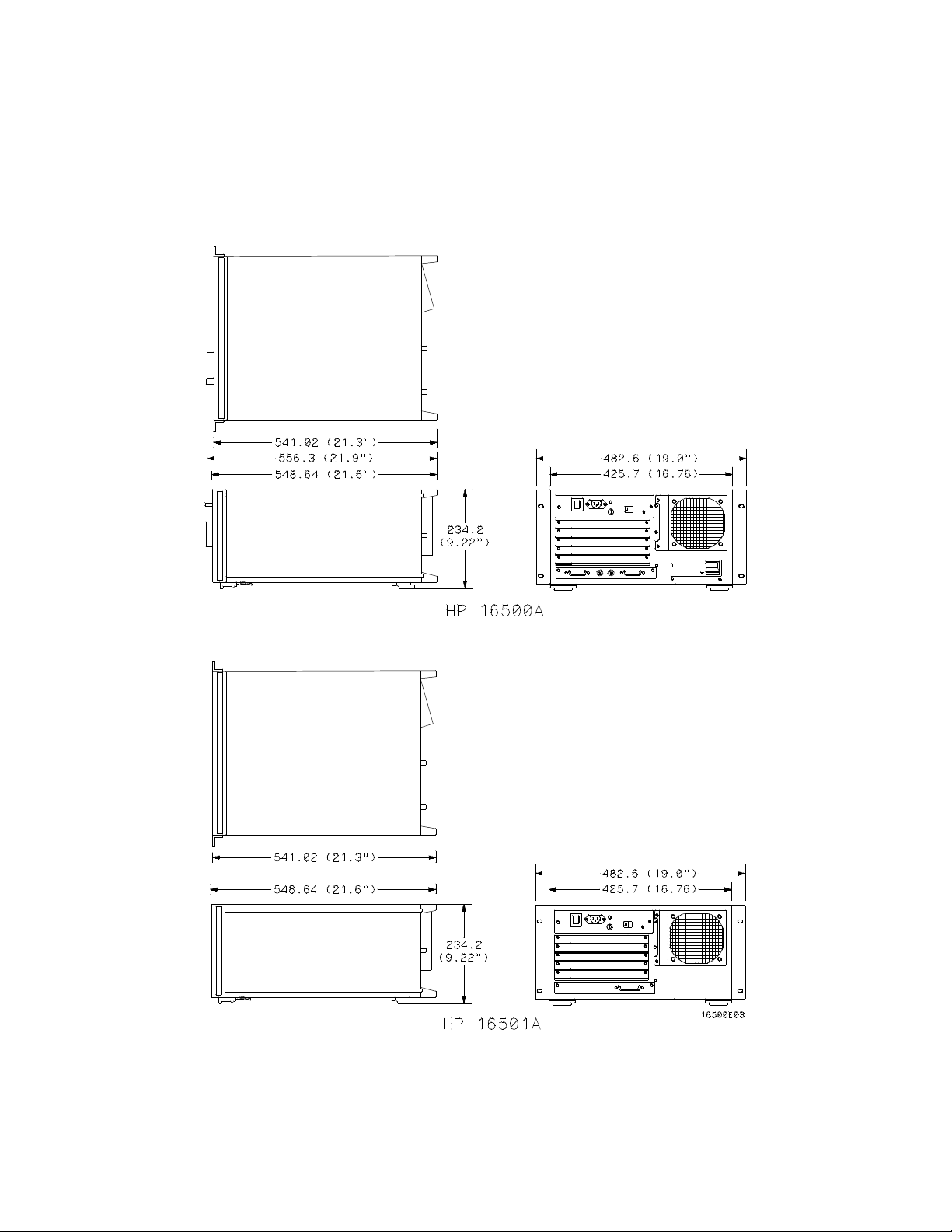
Dimensions:
Refer to figure 1-1 for dimensional detail.
1-5
Page 14
HP 16500A/16501A - General Information
1-6
Figure 1-1. Dimensional Detail
Page 15

HP 16500A/16501A - General Information
Table 1-2. Recommended Test Equipment
Instrument Critical Specification Recommended Model Use*
State Analyzer 10 MHz Acquisition Speed
22 Channels
Oscilloscope 100 MHz Bandwidth HP 54501A T
RS-232C
Loopback
Connector
Voltmeter 3 1/2 Digit Resolution HP 3468A T
* A=Adjustments P=Performance Tests T=Troubleshooting
HP 1651B T
HP Part No.
01650-63202
T
1-7
Page 16

TABLE OF CONTENTS
Section II
Installation Page
2-1. Introduction......................................................................................................................2-1
2-2. Safety Considerations.....................................................................................................2-1
2-3. Initial Inspection...............................................................................................................2-1
2-4. Operating Disk Installation ..............................................................................................2-1
2-5. Power Requirements.......................................................................................................2-1
2-6. Line Voltage Selection.....................................................................................................2-1
2-7. Power Cable....................................................................................................................2-2
2-8. User Interface..................................................................................................................2-4
2-9. HP-IB Interfacing.............................................................................................................2-5
2-10. HP-IB Address Selection.................................................................................................2-5
2-11. HP-IB Interface Functions...............................................................................................2-8
2-12. RS-232C Interface...........................................................................................................2-8
2-13. Baud Rate Selection........................................................................................................2-10
2-14. Degaussing the Display...................................................................................................2-12
2-15. Operating Environment ...................................................................................................2-12
2-16. Storage and Shipment.....................................................................................................2-12
2-17. Packaging........................................................................................................................2-12
2-18. Tagging for Service.........................................................................................................2-12
2-19. Cleaning Requirements...................................................................................................2-12
2-20. HP 16501A Expansion Frame Installation.......................................................................2-13
Page 17

HP 16500A/16501A - Installation
SECTION II
Installation
2-1. Introduction
This section contains information and instructions
necessary for setting up the HP 16500A/16501A
Logic Analysis System. This includes inspection
procedures, power requirements, hardware
connections and configurations, and packaging
information.
2-2. Safety Considerations
The safety symbols used with Hewlett-Packard
instruments are illustrated in the front of this
manual. WARNING and CAUTION symbols and
instructions should be reviewed before operating
the instrument. These warnings and cautions
must be followed for your own protection and to
avoid damage to the instrument.
2-3. Initial Inspection
Inspect the shipping container for damage. If the
shipping container or cushioning material is
damaged, it should be kept until the contents of
the shipment have been checked for
completeness and the instrument has been
checked mechanically and electrically. The
contents of the shipment should be as listed in
"Accessories Supplied" in section 1. If the
contents are incomplete, if there is mechanical
damage or defect, or if the instrument does not
operate properly, notify the nearest
Hewlett-Packard Sales Office. If the shipping
container is damaged, or the cushioning material
shows signs of stress, notify the carrier as well as
the Hewlett-Packard Sales Office. Keep the
shipping material for carrier’s inspection. The
Hewlett-Packard Sales Office will arrange for
repair or replacement at Hewlett-Packard’s option
without waiting for a claim settlement.
2-4. Operating Disk Installation
The HP 16500A is shipped with yellow protective
disks in each disk drive. Before applying power to
the mainframe, remove the protective disks from
the front and rear disk drives, then install the
operating disk in one of the disk drives. Reinstall
the protective disks whenever the instrument is
transported.
2-5. Power Requirements
The HP 16500A and the HP 16501A each require
a power source of 115 Vac or 230 Vac, 48 to 66
Hz, 475 W maximum.
2-6. Line Voltage Selection
The instrument may be damaged if the Line
Voltage Select switch is not properly set.
When shipped from Hewlett-Packard, the Line
Select switch is set and an appropriate fuse is
installed for operating the instrument in the
country of destination.
2-1
Page 18
HP 16500A/16501A - Installation
To operate the instrument from a power source
other than the one set at Hewlett-Packard,
proceed as follows:
1. Turn the front panel switch to STBY and
turn the rear panel power switch to OFF.
Remove the power cord from the instrument.
2. Replacethemainfusewitha5A/250V
fuse for 230 V operation, or a 10 A/125 V
fuse for 115 V operation.
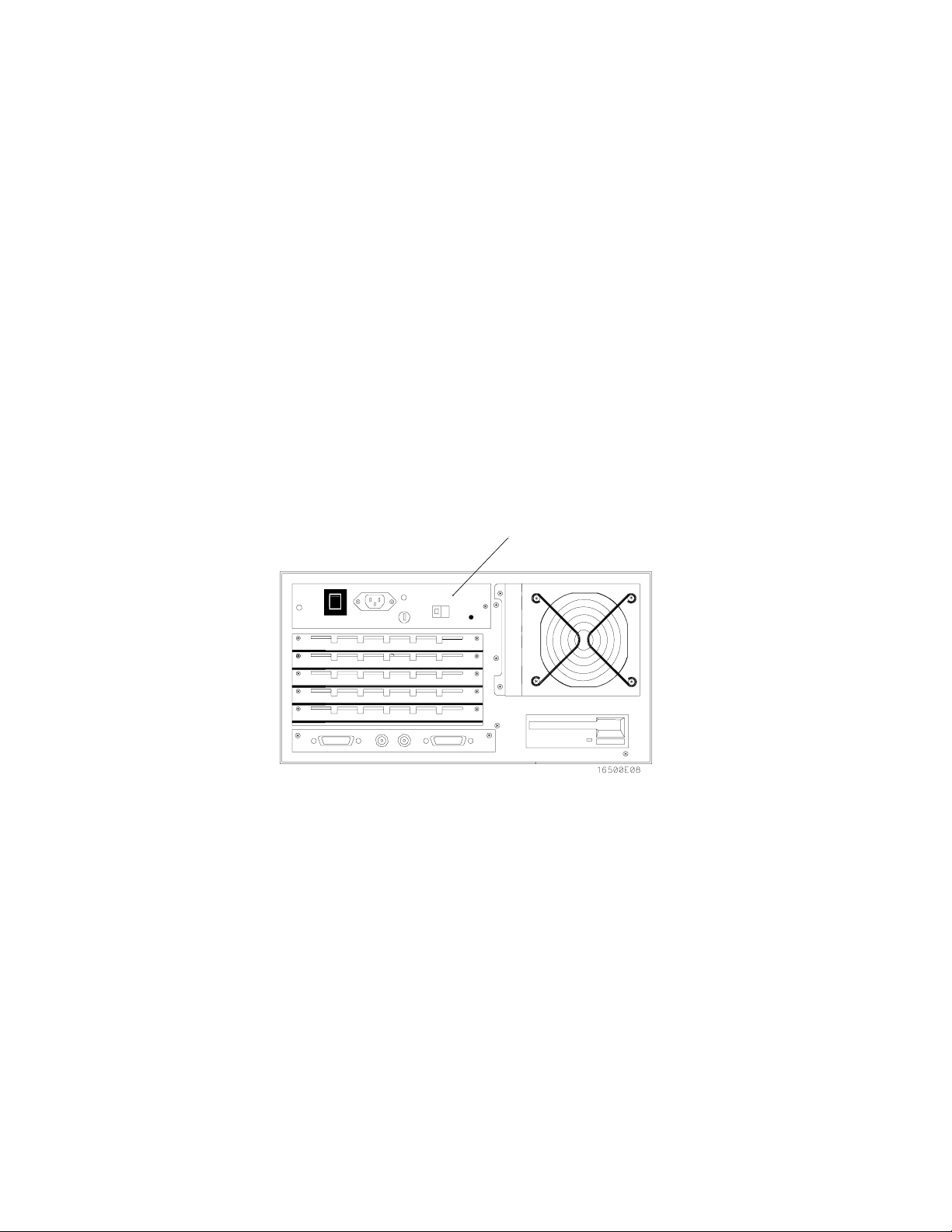
3. Set the rear panel Line Select switch for the
desired line voltage. See figure 2-1.
4. Reconnect the power cord, turn on the rear
panel power switch, then continue normal
operation.
2-7. Power Cable
This instrument is equipped with a three-wire
power cable. When connected to an appropriate
ac power outlet, this cable grounds the instrument
cabinet. The type of power cable plug shipped
with the instrument depends on the country of
destination. See figure 2-2 for option numbers of
available power cables and plug configurations.
Line Select Switch
2-2
Figure 2-1. Line VoltageSelection
Page 19
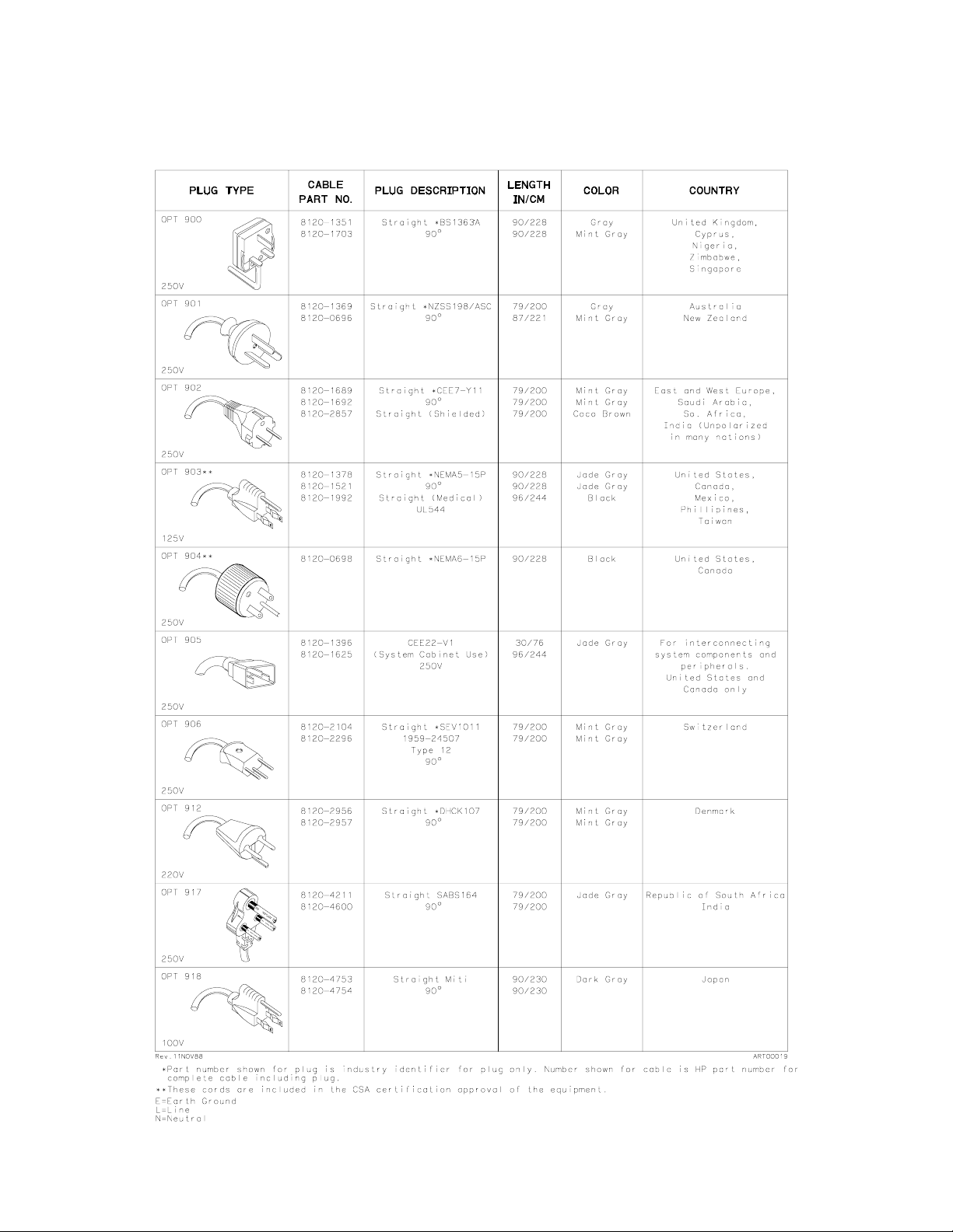
Figure 2-2. Power Cord Configurations
HP 16500A/16501A - Installation
2-3
Page 20
HP 16500A/16501A - Installation
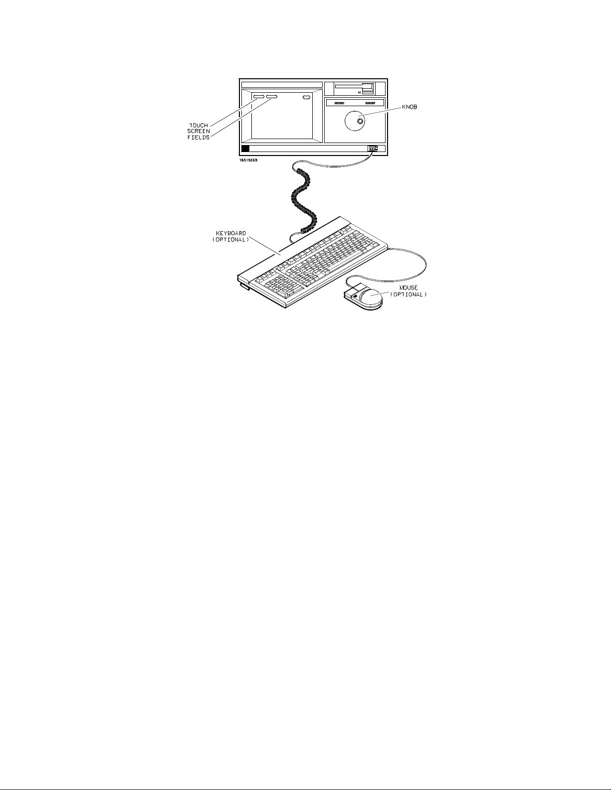
Figure 2-3. HP 16500A User Interface Devices
2-8. User Interface
Four devices may be used to interface with the
HP 16500A and all installed modules, the
touchscreen, the front panel knob, the optional
keyboard, and the optional mouse. See figure 2-3.
For complete operating information refer to the
HP 16500A/16501A Logic Analysis System
Operation Reference Manual
Manual for each module installed.
The Touchscreen.
The touchscreen interface provides the main front
panel control or access to the menus. By touching
the appropriate field, you can access other menus,
configure the HP 16500A for making
measurements, and enter or change alphanumeric
data.
The Front Panel Knob
The front panel knob is used to increment or
decrement numeric fields and to roll the display.
Rolling the display means scrolling through
information on screen.
and the Operating
The Optional Mouse
The mouse is an optional user interface accessory
(HP 46060A). The mouse functions in the same
way as the touchscreen and the knob. Moving it
about on a hard, flat surface will move the cursor
over the entire screen. To select a field, connect
the mouse to the front panel HIL connector and
move the mouse until the cursor rests in the
desired field. Press the left button of the mouse to
complete the selection of the field. To duplicate
the knob function, press and hold the right button
of the mouse and move it over the desktop. When
the correct numerical value or the correct function
has been selected, stop moving the mouse and
release the right button.
The Optional Keyboard
The keyboard is an optional user interface
accessory (HP E2427A). The keyboard can be
used interchangeably with the knob, the
touchscreen, and the mouse for all menu
applications.
2-4
Page 21
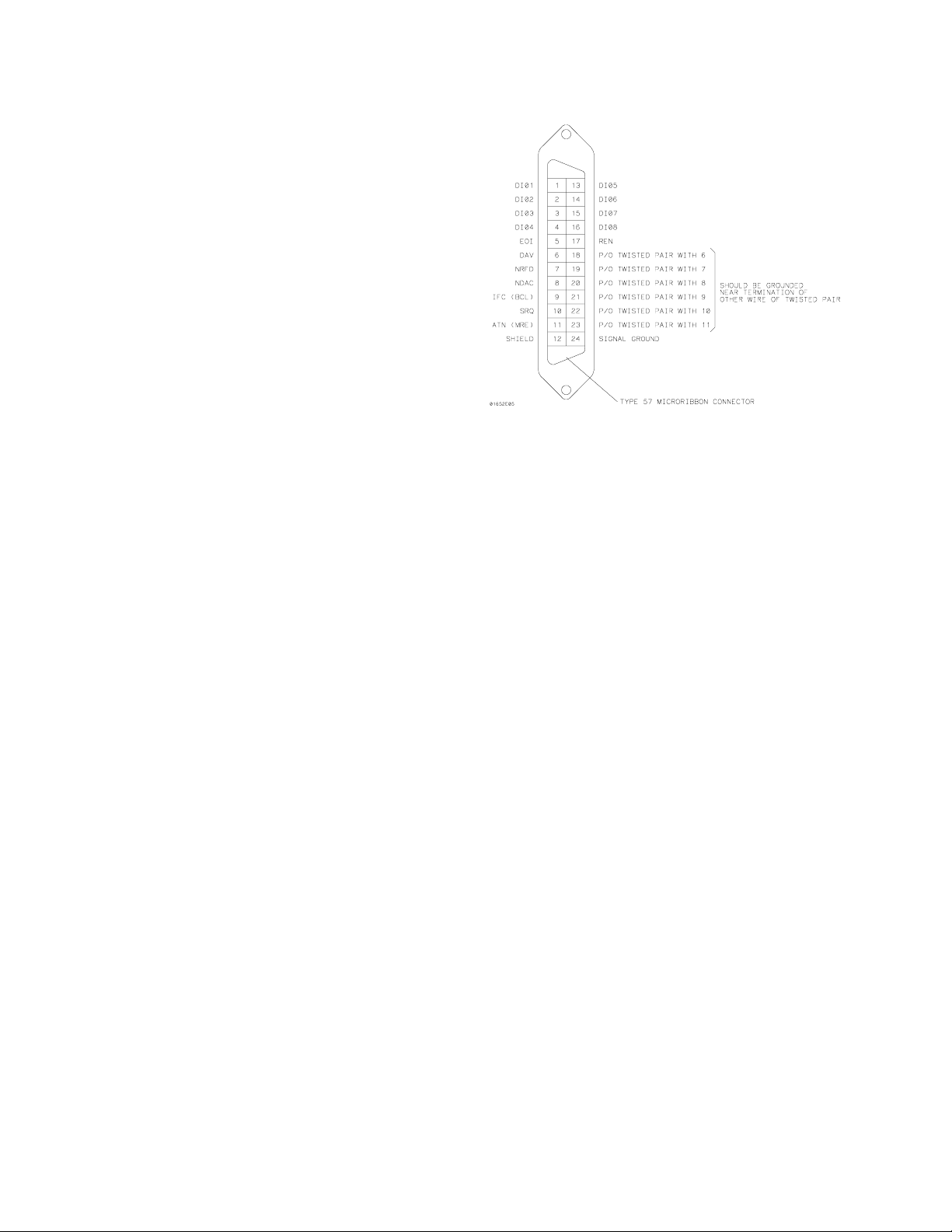
2-9. HP-IB Interfacing
The Hewlett-Packard Interface Bus (HP-IB) is
Hewlett-Packard’s implementation of IEEE
Standard 488-1978, "Standard Digital Interface for
Programmable Instrumentation." HP-IB is a
carefully defined interface that simplifies the
integration of various instruments and computers
into systems. The interface makes it possible to
transfer messages between two or more HP-IB
compatible devices. HP-IB is a parallel bus of 16
active signal lines divided into three functional
groups according to function.
Eight signal lines, called data lines, are in the first
functional group. The data lines are used to
transmit data in coded messages. These
messages are used to program the instrument
function, to transfer measurement data, and to
coordinate instrument operation. Input and output
of all messages, in bit parallel-byte serial form, are
also transferred on the data lines. A 7-bit ASCII
code normally represents each piece of data.
HP 16500A/16501A - Installation
Figure 2-4. HP-IB Interface Connector
2-10. HP-IB Address Selection
Data is transferred by means of an interlocking
"handshake" technique, which permits data
transfer (asynchronously) at the rate of the
slowest active device used in that transfer. The
data byte control lines coordinate the handshaking
and form the second functional group.
The remaining five general interface management
lines (third functional group) are used to manage
the devices connected to the HP-IB. This includes
activating all connected devices at once and
clearing the interface.
The connections to the HP-IB connector on the
rear panel are shown in figure 2-4.
Each instrument connected to the HP-IB interface
bus requires a unique address. The address
provides a method for the system computer to
select individual instruments on the bus. The
address of the HP 16500A defaults at power-on to
decimal "07". The corresponding ASCII code is a
listen address of "’" and a talk address of "G".
2-5
Page 22
HP 16500A/16501A - Installation
To change the address of the HP 16500A, proceed as follows:
1. With the operating system disk in one of the disk drives, turn the instrument on to obtain the System
Configuration menu. See figure 2-5.
Figure 2-5. System Configuration Menu
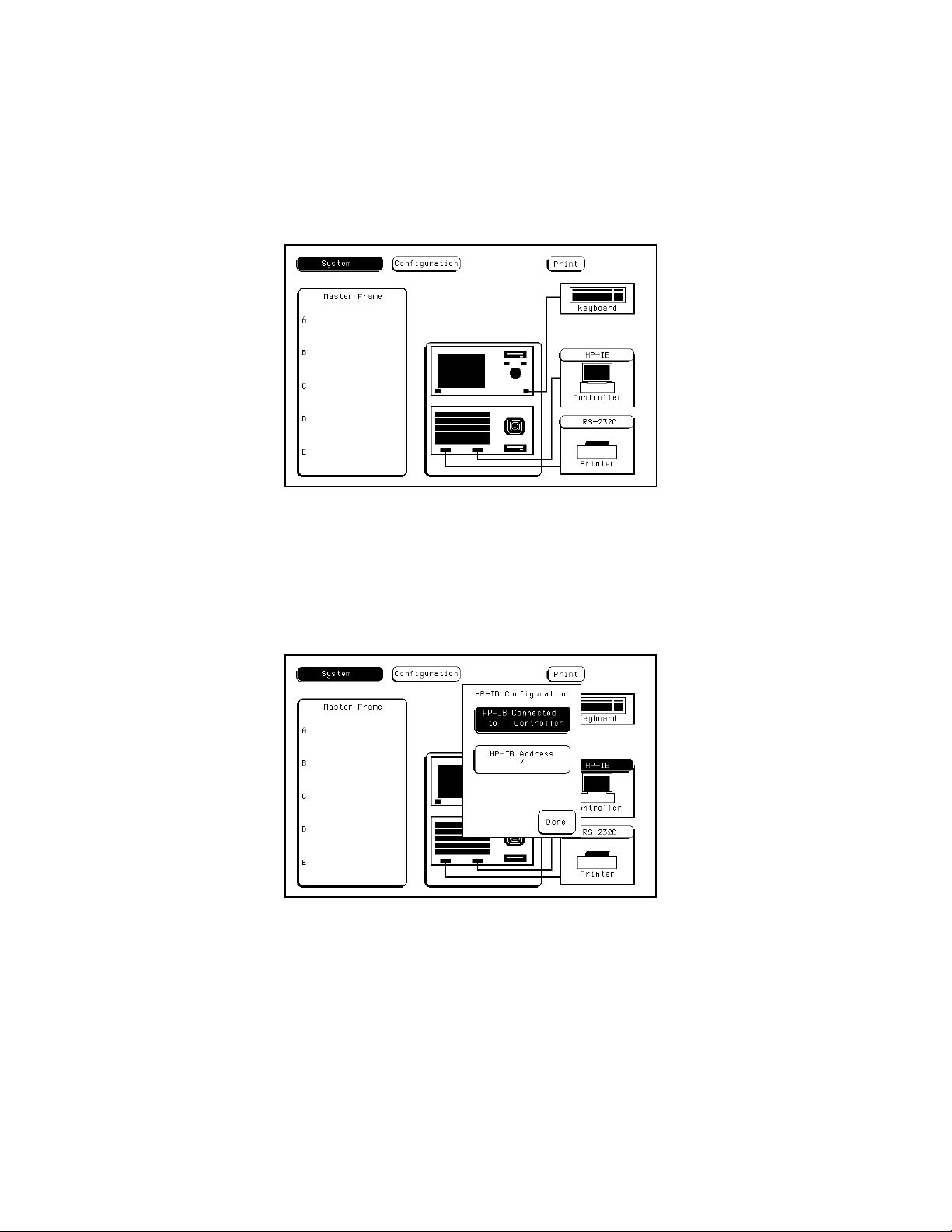
2. Touch the HP-IB field to obtain the HP-IB Configuration Menu. See figure 2-6.
Figure 2-6. HP-IB Configuration Menu
2-6
Page 23
HP 16500A/16501A - Installation
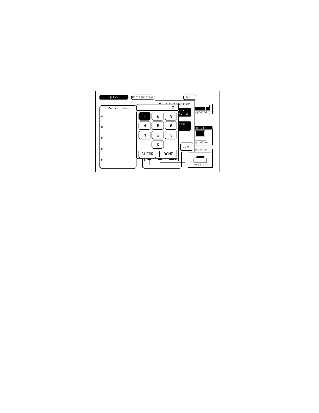
3. Rotate the knob to select the desired HP-IB address. The address number is shown in the HP-IB
Address field. The address number may also be entered via the keypad. Touch the HP-IB field
again to bring up the keypad. Select the new number using the keypad, then touch Done to enter
Figure 2-7. HP-IB Configuration with Keypad
address. See figure 2-7.
4. Touch Done to exit the HP-IB Configuration menu.
the new selected
2-7
Page 24

HP 16500A/16501A - Installation
2-11. HP-IB Interface Functions
The HP-IB interface offers 10 functions to support communications. Table 2-1 lists the HP-IB functions
that the HP 16500A uses.
Table 2-1. HP 16500A HP-IB Functions
HP 16500A
Mne-
monic Interface Function Name
SH
AH
T
L
SR
RL
PP
DC
DT
C
E
Source Handshake
Acceptor Handshake
Talker (or TE=Extended Talker)
Listener (or LE=Extended Listener)
Service Request
Remote Local
Parallel Poll
Device Clear
Device Trigger
Any Controller
Electrical Characteristics
Implemen-
tation
SH1
AH1
T5
L4
SR1
RL1
PP1
DC1
DT1
C0
E2
2-12. RS-232C Interface
The HP 16500A interfaces with RS-232C communication lines through a standard 25-pin D connector.
The HP 16500A is compatible with RS-232C protocol.
When a hardwire handshake method is used, the Data Terminal Ready (DTR) line (pin 20 on the Computer/Modem connector) is used to signal whether space is available in the logical I/O buffer for more
data. Table 2-2 shows the RS-232C signal definitions.
2-8
Page 25

Table 2-2. RS-232C Signal Definitions
Pin No. Function
1
Protective Ground
HP 16500A/16501A - Installation
RS-232C
Standard Signal Direction and Level
AA
Not applicable
2
3
4
5
6
7
8
Transmitted Data (TD)
Received Data (RD)
Request to Send (RTS)
Clear to Send (CTS)
Data Set Ready (DSR)
Signal Ground (SGND)
Data Carrier Detect (DCD)
BA
BB
CA
CB
CC
AB
CF
Data from Mainframe
High = Space = "0" = +12V
Low = Mark = "1"= -12V
Data to Mainframe
High = Space = "0" = +3V to +25V
Low = Mark = "1" = -3V to -25V
Signal from Mainframe
High = ON = +12V
Low = OFF = -12V
Signal to Mainframe
High = ON = +3V to +12V
Low = OFF = -3V to -25V
Signal to Mainframe
High = ON = +3V to +25V
Low = OFF = -3V to -25V
Not applicable
Signal to Mainframe
High = ON = +3V to +25V
Low = OFF = -3V to -25V
20
23
Data Terminal Ready (DTR)
Data Signal Rate Selector
CD
CH/CI
Signal from Mainframe
High = ON = +12V
Low = OFF = -12V
Signal from Mainframe
Always High = ON = +12V
2-9
Page 26
HP 16500A/16501A - Installation
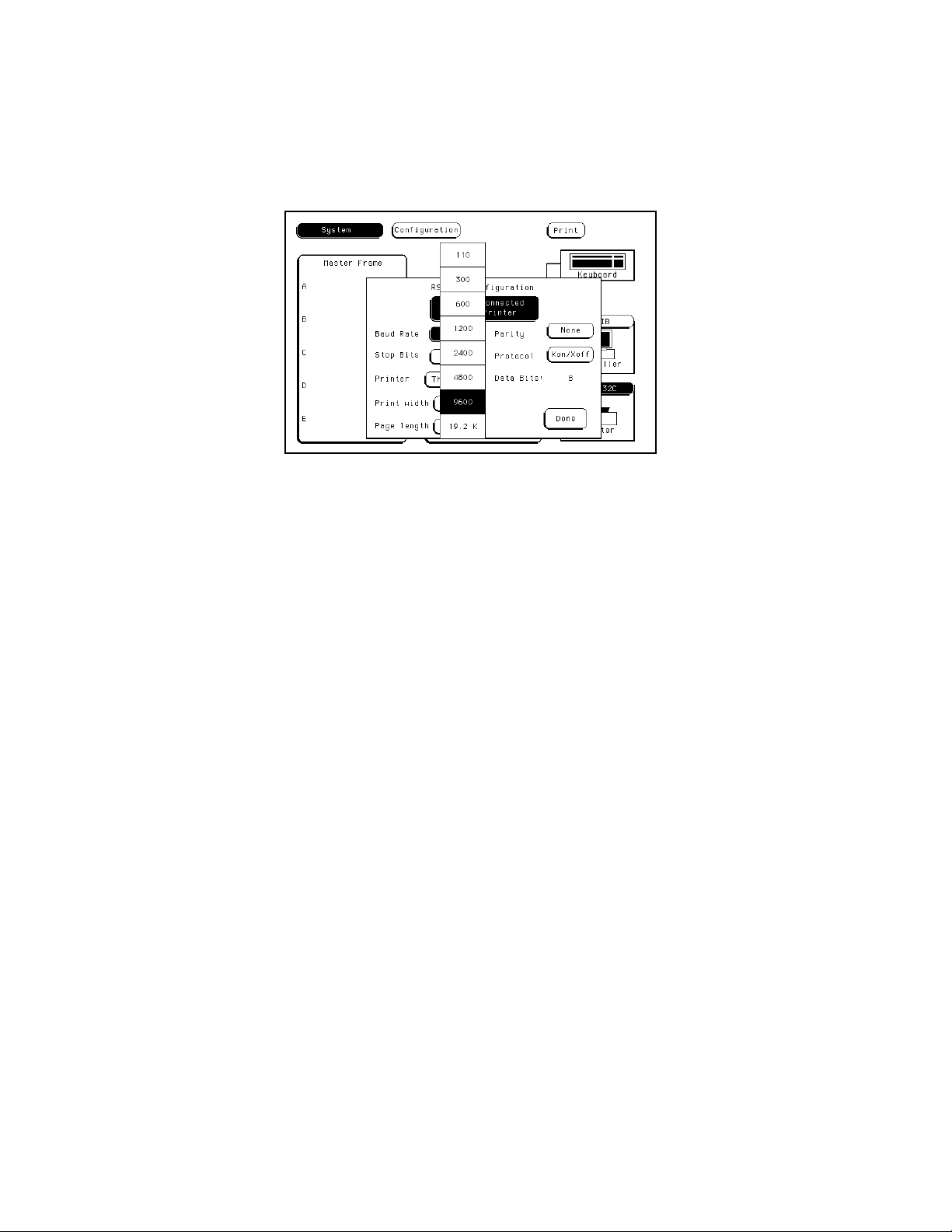
2-13. Baud Rate Selection
The baud rate of the HP 16500A is set at power-on for 9600 baud. To change the baud rate, proceed as
follows:
1. With the operating system disk in one of the disk drives, turn on the instrument to obtain the System
Configuration menu. See figure 2-8.
Figure 2-8. System Configuration Menu
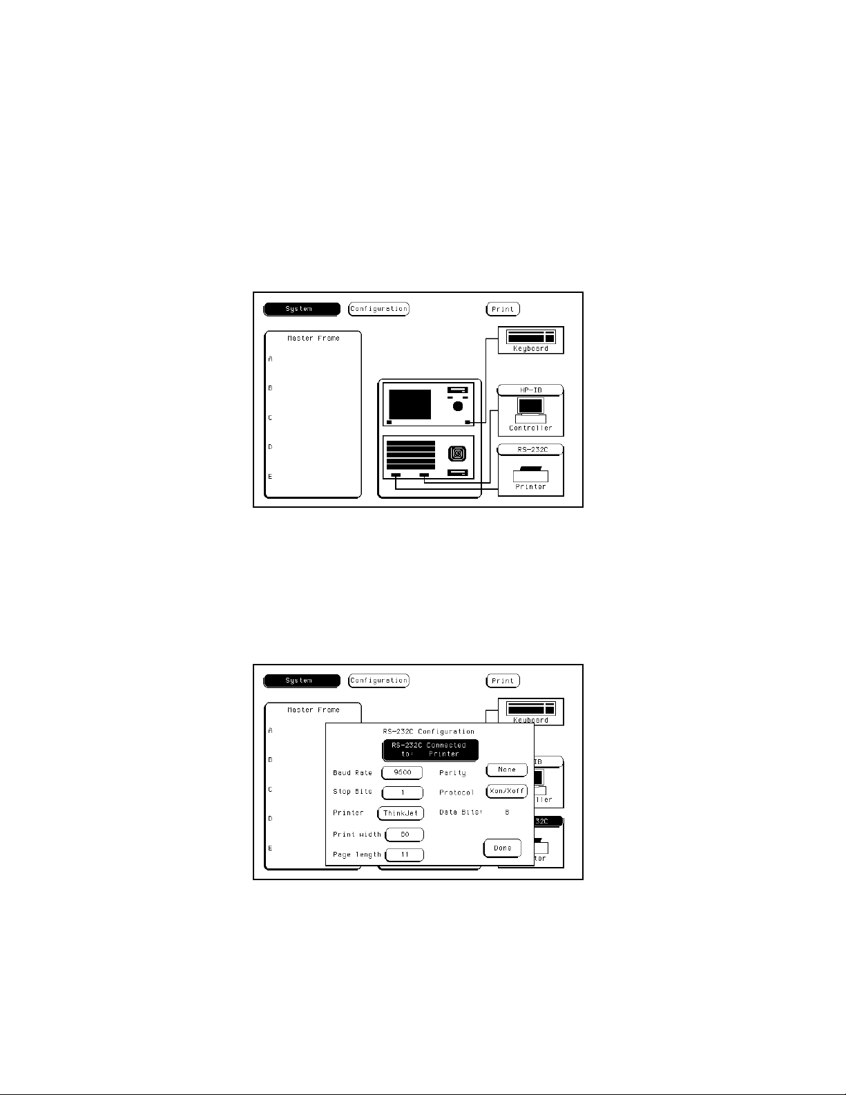
2. Touch the RS-232C field in the lower right corner of the screen to obtain the RS-232C configuration
menu. See figure 2-9.
Figure 2-9. RS-232C Configuration Menu
2-10
Page 27
HP 16500A/16501A - Installation
3. Touch the Baud Rate field, then select the required r ate. See figure 2-10. Make any other changes
to the RS-232C configuration while you are in this menu.
Figure 2-10. Baud Rate Pop-Up Menu
4. When the RS-232C configuration is correct, touch the Done field and the System Configuration
screen will be displayed.
2-11
Page 28

HP 16500A/16501A - Installation
2-14. Degaussing the Display
After the HP 16500A has been used for awhile,
the CRT may become magnetized and the color or
other display data may become distorted. To
correct these problems, press the Degauss button
on the power supply rear panel several times. If
the instrument has been subjected to strong
magnetic fields, it may be necessary to degauss
the CRT with a conventional external
television-type degaussing coil or to replace the
CRT.
2-15. Operating Environment
The operating environment is listed in table 1-2.
Note should be made of the non-condensing
humidity limitation. Condensation within the
instrument can cause poor operation or
malfunction. Protection should be provided
against internal condensation.
The HP 16500A/16501A will operate at all
specifications within the temperature and humidity
range given in table 1-2. However, reliability is
enhanced by operating the instrument within the
following ranges.
Temperature: +20 °Cto+35 °C
(+68 °Fto+95 °F)
Humidity: 20% to 80% non-condensing
• Remove the disks from the disk drives and
install the yellow shipping disks.
• Wrap the instrument in heavy paper or plastic.
• Use a strong shipping container. A
double-wall carton made of 350-lb test
material is adequate.
• Use a layer of shock-absorbing material, 70
to 100 mm (3 to 4 inches) thick, around all
sides of the instrument to provide firm
cushioning and to prevent movement inside
the container. Protect the control panel with
cardboard.
• Seal the shipping container securely.
• Mark the shipping container FRAGILE to
ensure careful handling.
• In any correspondence, refer to instrument by
model number and by full serial number.
2-18. Tagging for Service
If the instrument is to be shipped to a
Hewlett-Packard office for service or repair, attach
a tag showing the owner (with address), the
complete instrument serial number, and a
description of the service required.
2-16. Storage and Shipment
The instrument may be stored or shipped in
environments within the following limits:
Temperature: -40 °Cto+75°C
Humidity: Up to 90% at 65 °C
Altitude: Up to 15,300 meters (50,000 feet)
The instrument should also be protected from
temperature extremes which cause condensation
within the instrument.
2-17. Packaging
Use the following general instructions for
repacking the instrument with commercially
available materials.
2-12
2-19. Cleaning Requirements
Use mild soap and water to clean the
HP 16500A/16501A Do not use ammonia-based
products to clean the screen. Ammonia damages
the screen coating.
Clean the CRT display and surrounding area
regularly. Do not place tape or other foreign
material on the screen.
Note
If the CRT display is not clean or if foreign
objects block the edges of the screen,
touchscreen failures can occur.
Vacuum the ventilation slots on the sides of the
instrument and on the rear-panel fan whenever
there is a visible amount of dust on them.
Page 29
HP 16500A/16501A - Installation
2-20. HP 16501A Expansion Frame Installation
The effects of ELECTROSTATIC DISCHARGE can damage electronic
components. Use grounded wriststraps and mats when you are performing any
kind of service to this instrument.
Installation Considerations
• The mainframe interface card can be installed in any available card slot in the HP 16500A main-
frame.
• Cards or filler panels in the HP 16500A located below the empty slot intended for installation do
not have to be moved.
Procedure
1. Turn off the HP 16500A mainframe power switch, then unplug the power cord. Disconnect any input
connections.
2. Verify the correct setting of the Line Select switch located on the rear panel of the HP 16501A. See
section 2-6, "Line Voltage Selection."
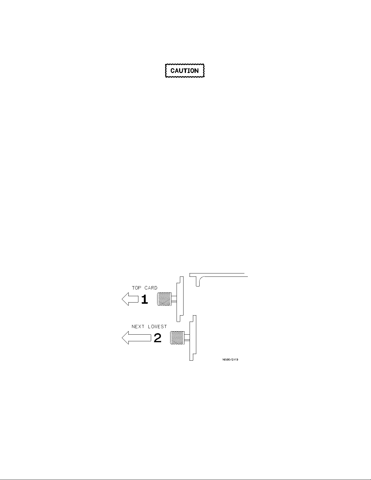
3. Starting from the top, loosenthumb screws on filler panels and cards that need to be moved.
Starting from the top, pull the cards and filler panels half-way out. See figure 2-11.
4. Remove the filler panel or card that is in the slot intended for the mainframe interface card. Slide the
mainframe interface card into the card cage of the HP 16500A mainframe.
Figure 2-11. Endplate Overlap
2-13
Page 30
HP 16500A/16501A - Installation
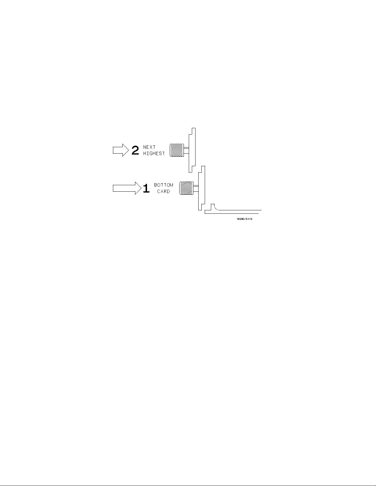
5. Reposition all cards and filler panels so that the endplates overlap properly.
6. Firmly seat the bottom card into the backplane connector of the mainframe. Keep applying
pressure to the center of the card endplate while tightening the thumb screws finger tight.
Repeat for all cards and filler panels in a bottom to top order. See figure 2-12.
Note
Any filler panels that are not used should be kept for future use. Filler panels
must
be installed in all unused card slots for correct air circulation.
Figure 2-12. Endplate Overlap
2-14
Page 31

HP 16500A/16501A - Installation
Note
In order to ensure correct insertion, the 68-pin "D" connectors on each end of the
interface cable are asymmetric in shape. They only fit into their respective ports
on the cards when oriented to match the shape of the ports.
7. Insert one end of the interface cable into the port located on the mainframe interface card in the
HP 16500A. Insert the other end of the interface cable into the port located on the expansion
interface card in the HP 16501A.
Note
When connecting the interface cable, you will hear two clicks. Make sure the
cable connector is properly seated into the port by pulling the connector without
pressing the release tabs. If the connector is properly seated, it will remain
connected to the port.
Figure 2-13 shows the HP 16500A and HP 16501A configuration.
Figure 2-13. Configuration
2-15
Page 32

HP 16500A/16501A - Installation
8. Turn on the HP 16500A/16501A Logic Analysis System.
a. Connect a power cord to each frame.
b. Turn on the line switch located on the rear panel of each frame.
c. Turn on the power standby switch located on the front-panel of the HP 16500A mainframe.
When the power-up tests are complete, the HP 16500A mainframe screen shows the
Mainframe Interface Card in one of the card slots. See figure 2-14.
Figure 2-14. System Configuration Menu
2-16
Page 33

TABLE OF CONTENTS
Section III
Performance Tests Page
3-1. Introduction.......................................................................................................................3-1
Page 34

3-1. Introduction
This section normally contains the performance
verification tests. Because there are no
specifications for the HP 16500A/16501A to test,
there are no performance tests.
HP 16500A/16501A - Performance Tests
SECTION III
Performance Tests
3-1
Page 35

TABLE OF CONTENTS
Section IV
Adjustments Page
4-1. Introduction......................................................................................................................4-1
4-2. Degaussing the Display...................................................................................................4-1
4-3. Safety Considerations.....................................................................................................4-1
4-4. Adjustment Test Patterns................................................................................................4-2
4-5. Color Display Module Adjustments .................................................................................4-7
Page 36

HP 16500/16501A - Adjustments
SECTION IV
Adjustments
4-1. Introduction
The HP 16500A/16501A requires no adjusting
when used in a normal environment. The
procedure given in this section is for the color
module. Do not perform these adjustments as
part of regular maintenance. Observe the
following rules before making any color module
adjustments.
Do not perform this procedure as normal
maintenance.
Make adjustments only if the instrument has
been subjected to extreme magnetic
environments and the colors are incorrect.
Before making any adjustments, try
degaussing the unit using the rear panel
degaussing switch or a color television type
degaussing coil.
4-2. Degaussing the Display
After the instrument has been used for awhile, the
CRT may become magnetized and the color or
other data may become distorted. To correct
these problems, press the Degauss button on the
power supply rear panel several times. If the
instrument has been subjected to strong magnetic
fields, it may be necessary to degauss the CRT
with a conventional external television-type
degaussing coil.
4-3. Safety Considerations
Although this instrument has been designed in
accordance with international safety standards,
general safety precautions must be observed
during all phases of operation, service, and repair
of the instrument. Failure to comply with the
precautions listed in the Safety Summary at the
front of this manual, or with specific warnings
given throughout this manual, could result in
serious injury or death. Service adjustments
should be performed only by qualified service
personnel.
Only qualified personnel who are familiar
with color CRT convergence procedures
should perform this adjustment.
Before adjustments are made, mark the
position of the potentiometers. This process
allows you to return the adjustments to their
original starting position.
Read the Safety Considerations at the front
of this manual before performing
adjustment procedures. Disconnect the
instrument from all voltage sources before it
is opened for any adjustment, replacement,
maintenance, or repair.
4-1
Page 37

HP 16500A/16501A - Adjustments
4-4. Adjustment Test Patterns
Six test patterns are required for adjusting the color module: one white cross hatch pattern, one white full
screen raster, a full screen pattern for each primary color (red, green, blue), and one black full screen
raster.
Access to the test patterns is gained through the Mainframe Test system. To access the test patterns,
proceed as follows:
1. Insert the operating system disk into one of the disk drives, then turn on the instrument to obtain
the System Configuration menu. See figure 4-1.
Figure 4-1. System Configuration Menu
2. Touch the Configuration field, then touch the Test field from the pop-up menu. See figure 4-2.
Figure 4-2. Accessing the Test System
4-2
Page 38

HP 16500A/16501A - Adjustments
3. Verify that test files are on an installed disk. Touch the field close to the center of the screen to load
the Test System. See figure 4-3.
Figure 4-3. Loading the Test System
4. After the Test System has been loaded from the disk, the Test Configuration will be displayed. See
figure 4-4.
Figure 4-4. Test System Configuration
4-3
Page 39

HP 16500A/16501A - Adjustments
5. Touch the Test System field, then select Mainframe Test from the pop-up menu. See figure 4-5.
Figure 4-5. Selecting Mainframe Test Menu
6. The Mainframe Test menu is now displayed. See figure 4-6. Select the Color Display Test field
to display the white cross hatch test pattern, which is the first test pattern in the system. See
figure 4-7.
Figure 4-6. Mainframe Test Menu
4-4
Page 40

HP 16500A/16501A - Adjustments
7. With every touch of the Continue field, the next test pattern will be displayed. See figure 4-7.
Figure 4-7. Selecting the Test Patterns
When Continue is selected from the black raster pattern, the Mainframe Test menu will be
displayed. Notice that the status of the Display Test field has changed to TESTED.
8. To exit the Mainframe Test system and to reload the mainframe operating system, touch the
Mainframe Test field. Then touch the Test System field from the pop-up menu shown in
figure 4-8. The Test System configuration will be displayed.
Figure 4-8. Exiting Mainframe Test System
4-5
Page 41

HP 16500A/16501A - Adjustments
9. Touch the Configuration field, then touch Exit T est. Install the operating system disk into one of
the disk drives, then touch the field close to the center of the screen to reload the mainframe
operating system. See figure 4-9.
Figure 4-9. Exiting Test System Configuration
10. After the operating system has been reloaded, the System Configuration will be displayed. See
figure 4-10.
Figure 4-10. System Configuration
4-6
Page 42

HP 16500A/16501A - Adjustments
4-5. Color Display Module Adjustments
Description:
The Color Display Module is adjusted to compensate for external magnetic influences causing
misconvergence.
Note
DO NOT continue with this procedure before first degaussing the CRT screen
using the rear panel degaussing switch. In extreme cases of magnetism, it may
be necessary to degauss the CRT using a conventional external television-type
degaussing coil. During any of the following adjustments, the CRT module must
face west.
Equipment Required:
Nonmetallic Adjustment Tool.......................................................................HP Part Number 8710-1355
Procedure:
Note
The following adjustments are broken down into adjustment groups. The
sequence of the adjustment groups must be followed due to the interaction and
dependency of one adjustment to another. The adjustment group sequence is
shown in the adjustment flow diagram in figure 4-11. There will be cases where
not all the adjustment groups will be used. For example, if the Geometry
Adjustment Group corrects the problem, this will be the only group used.
4-7
Page 43

HP 16500A/16501A - Adjustments
4-8
Figure 4-11. CRT Module Adjustment Flow Diagram
Page 44

HP 16500A/16501A - Adjustments
Geometry Adjustments
1. From the Mainframe Test System, select the Display Test menu. Select the white cross hatch test
pattern. Refer to section 4-4, "Adjustment Test Patterns," for accessing the test patterns.
2. Preset the front panel BACKGROUND control to mechanical center.
3. Preset the front panel BRIGHTNESS control to maximum.
4. Preset H.SUB SHIFT (RV006) and V.SUB SHIFT (RV008), located on the bottom PC board, to
mechanical center.
5. Using a flexible ruler, adjust H.SIZE (RV504) and V.HEIGHT (RV502), located on the left hand side
PC board, so that the border of the cross-hatch is 120.5 mm (4.74 in.) vertically and 161 mm
(6.34 in.) horizontally.
6. Adjust V.CENT (RV510) and H.CENT (RV503), located on the left hand side PC board, to center
pattern.
7. Adjust PIN AMP (RV506), located on the left hand side PC board, to eliminate pincushion distortion
in the vertical lines of the cross-hatch pattern as shown in figure 4-12.
Figure 4-12. PIN AMP Adjustment
4-9
Page 45

HP 16500A/16501A - Adjustments
Geometry Adjustments (Continued)
8. Set the instrument on its left side, color module side up, then remove the bottom rail. See
figure 4-13.
Note
Leave the instrument standing on its left side until the PIN PHASE adjustment
has been completed.
4-10
Figure 4-13. Bottom Rail Removal
Page 46

HP 16500A/16501A - Adjustments
Geometry Adjustments (Continued)
9. Adjust PIN PHASE (RV505), located on the left side PC board, to eliminate pin phase distortion in
vertical lines of cross-hatch pattern as shown in figure 4-14.
Figure 4-14. PIN PHASE Adjustment
10. Reinstall the bottom rail.
11. Adjust the TOP PIN (RV511), located on the left hand side PC board, so the top horizontal line is
parallel with the center horizontal line.
12. Adjust the BOTTOM PIN (RV512), located on the left hand side PC board, so the bottom horizontal
line is parallel with the center horizontal line.
4-11
Page 47

HP 16500A/16501A - Adjustments
Focus Adjustment
Note
Geometry adjustments must be performed before making the focus adjustment.
1. Remove the rear and side fan. Refer to section 6, "Service," for the fan removal procedures.
2. From the Display Test menu of the Mainframe Test system, select the white cross-hatch test pattern.
3. Adjust FOCUS (RV701), located on the rear PC board, for best overall focus.
Landing and Convergence Adjustment Preparation
1. From the Display Test menu, select a white raster pattern and check for color purity. Repeat this
step using the Red, Green, and Blue raster patterns and check for color purity.
If the color purity is correct, do not perform this Landing and Convergence adjustment.
2. Turn off the instrument, then disconnect the power cord. Loosen the deflection yoke clamp screw.
3. Remove the deflection yoke spacers by moving the deflection yoke towards the rear of the
instrument, then by removing the spacers.
Note
The deflection yoke spacers are tapered rubber blocks located between the front
of the yoke and the rear of the CRT funnel.
4. Plug the power cord into the instrument, then turn on the instrument. For thermal stability, allow the
instrument to warm up for 20 minutes.
Exercise caution when moving purity magnets. Power is applied to the
instrument and high voltages are present around the CRT.
4-12
Page 48

HP 16500A/16501A - Adjustments
Landing Adjustment
1. From the Display Test menu, select the white raster (full screen display).
2. Turn the front panel BRIGHTNESS Control to maximum.
3. Degauss the entire CRT screen by pressing the Degaussing switch located on the rear panel of the
instrument.
Note
In cases where your environment or the shipping environment has caused high
levels of magnetization to take place, you may need to externally degauss the
CRT using a conventional television-type degaussing coil to completely degauss
the CRT.
Figure 4-15. Purity Magnet Centering
magnet tabs to mechanical center. See figure 4-15.
5. Select the green raster from the Display Test menu.
4. Set the purity
4-13
Page 49

HP 16500A/16501A - Adjustments
Landing Adjustment (Continued)
6. Move the deflection yoke towards the rear of the instrument, until the left edge of the raster turns red
Figure 4-16. Purity Magnet Adjustment Raster
and the right edge of the
raster turns blue. See figure 4-16.
7. Adjust the purity magnets until green is in the center of the raster with red and blue bands evenly
distributed on the sides. See figure 4-15. The purity magnets need no more than ±15° movement
from the mechanical center.
8. Move the deflection yoke forward until the entire raster is green.
Note
The landing adjustment is easier if the yoke is moved all the way forward and
then moved backward until the raster is completely green.
9. Replace the green raster with a full screen red raster. Check for proper landing adjustment (color
purity). Select a blue full-screen raster and check it for proper landing adjustment.
4-14
Page 50

HP 16500A/16501A - Adjustments
Landing Adjustment (Continued)
10. If the landing is not correct in step 9, repeat steps 6 through 9 for the best compromise. See
Figure 4-17. Landing and Purity Adjustment Guide
figure 4-17.
11. If the landing is not correct in step 10, readjust the purity magnets for the best landing of each color.
12. Turn off the instrument and remove the power cord. Reinstall the yoke spacers.
13. When the landing adjustment is complete, tighten the deflection yoke clamp screw just enough to
keep the yoke from moving. DO NOT over-tighten.
Note
While moving the deflection yoke forward and backward, rotate the yoke as
necessary to make the vertical edges of the raster parallel to the sides of the
instrument frame.
4-15
Page 51

HP 16500A/16501A - Adjustments
Static Convergence
1. Preset the front panel BACKGROUND control to mechanical center.
2. Preset the front panel BRIGHTNESS control to maximum.
3. Temporarily disconnect the power from the instrument and remove the PC board shield cover from
the rear of the CRT Display Module by prying evenly on all four sides.
4. Reapply the power and from the Display Test menu select the white cross-hatch test pattern.
5. Check the four dots located around the center intersection of the cross-hatch pattern for coincidence
of blue, red, and green dots. If the dots are not coincident, adjust H.STAT (RV703), located on the
rear PC board, to obtain horizontal coincidence and V.STAT (RV803), located on the bottom PC
board, to obtain vertical coincidence. See figure 4-18.
Note
Due to interaction, the BEAM LANDING will need to be readjusted if either
H.STAT or V.STAT adjustments are made. Once the BEAM LANDING is
readjusted, repeat step 5, if necessary, to obtain center-screen coincidence of
the dots.
4-16
Figure 4-18. Static Convergence
Page 52

HP 16500A/16501A - Adjustments
Dynamic Convergence
1. From the Display Test menu, select the white cross-hatch test pattern.
2. Adjust the Y BOW (RV805), located on the bottom PC board, to eliminate red, green, and blue
bowing at the top and bottom of the center vertical line. See figure 4-19.
Figure 4-19. Y BOW Adjustment
3. Adjust the Y BOW CROSS (RV804), located on the bottom of the PC board, to eliminate red, green,
and blue orthogonal misalignment at the top and bottom of the center vertical line. See figure 4-20.
Figure 4-20. Y BOW CROSS Adjustment
4-17
Page 53

HP 16500A/16501A - Adjustments
Dynamic Convergence (Continued)
4. Adjust the V.STAT TOP (RV801) and the V.STAT BOTTOM (RV802), located on the bottom PC
board. These two adjustments allow you to obtain coincidence of red, blue, and green where the
top and bottom horizontal lines intersect with the center vertical line. See figures 4-21 and 4-22.
Figure 4-21. V.STAT TOP Adjustment
Figure 4-22. V.STAT BOTTOM Adjustment
4-18
Page 54

HP 16500A/16501A - Adjustments
Dynamic Convergence (Continued)
5. Adjust the H.AMP (RV807), located on the bottom PC board, for equal amounts of misconvergence
Figure 4-23. H.AMP Adjustment
right and left sides of the screen. See figure 4-23.
Figure 4-24. H.TILT Adjustment
at the
6. Adjust
the H.TILT (RV806), located on the bottom PC board, for coincidence of red, green, and blue at the
right and left sides of the screen. See figure 4-24.
4-19
Page 55

HP 16500A/16501A - Adjustments
White Balance
1. From the Display Test menu, select a blank (colorless) raster.
Note
Any text on the screen will not affect this adjustment.
2. Set the front panel BACKGROUND and SUB BRT (RV901), located on the bottom PC board, to
mechanical center.
3. Set the front panel BRIGHTNESS and SUB CONT (RV902), located on the bottom PC board, to
mechanical center.
4. Set the G. DRIVE (RV921), B. DRIVE (RV931), and R. DRIVE (RV911), located on the bottom PC
board, to mechanical center.
5. Set the G.BKG (RV721), B.BKG (RV731), and R.BKG (RV711), located on the rear PC board, fully
counterclockwise (CCW).
6. Adjust the SCREEN (RV702), located on the rear PC board, until either a red, green, or blue raster
just starts to become visible. Note which color becomes visible first and do not adjust background
control (BKG) for that color in the next step.
7. Adjust the other two background (BKG) controls for the best white balance.
8. From the Display Test menu, select the white raster test pattern.
9. Set the front panel BRIGHTNESS control to maximum.
10. Observe the screen and adjust the DRIVE controls (RV921, RV931, and RV911), located on the
bottom PC board for the best white balance.
Note
Using an average piece of white photocopy paper, compare the white on the
CRT to the paper.
11. Repeat steps 1 through 3 and 6 through 10 until the white balance is acceptable.
12. Reinstall the cooling fans. Refer to section 6, "Service," for the fan installation procedures.
4-20
Page 56

TABLE OF CONTENTS
Section V
Replaceable Parts Page
5-1. Introduction......................................................................................................................5-1
5-2. Abbreviations...................................................................................................................5-1
5-3. Replaceable Parts List ....................................................................................................5-1
5-4. Exchange Assemblies.....................................................................................................5-1
5-5. Ordering Information .......................................................................................................5-1
5-6. Direct Mail Order System................................................................................................5-2
Page 57

HP 16500A/16501A - Replaceable Parts
SECTION V
Replaceable Parts
5-1. Introduction
This section contains information for ordering
parts. Table 5-1 lists abbreviations used in the
parts list. Table 5-2 and table 5-3 list all
replaceable parts in reference designator order.
5-2. Abbreviations
Table 5-1 lists abbreviations used in the parts list
and throughout the manual. In some cases, two
forms of the abbreviations are used, one all in
capital letters, and one in partial or no capitals.
This occurs because the abbreviations in the parts
list are always all capitals. However, in other parts
of the manual other abbreviation forms are used
with both lower and uppercase letters.
5-3. Replaceable Parts List
Table 5-2 shows the list of replaceable parts for
the HP 16500A and table 5-3 shows the list of
replaceable parts for the HP 16501A. The tables
are organized as follows:
• Exchange assemblies in alphanumerical
order by reference designation.
• Electrical assemblies in alphanumerical order
by reference designation.
• Chassis-mounted parts in alphanumerical
order by reference designation.
The information given for each part consists of the
following:
• Reference designator.
• Hewlett-Packard part number.
• Check digit (CD).
• Total quantity (Qty) in the instrument. The
total quantity for each part is only given once,
at the first appearance of the part number in
the list.
• Part description.
5-4. Exchange Assemblies
Some of the parts used in this instrument have
been set up on an exchange program. This allows
the customer to exchange a faulty assembly with
one that has been repaired, calibrated, and
performance-verified at Hewlett-Packard. The
cost of the exchange assembly is significantly less
than that of a new part.
Exchangeable assemblies are listed separately in
table 5-2 and in table 5-3, under the heading
"Exchange Assemblies." They usually have a part
number in the form XXXXX-695XX (where the
new part would be XXXXX-665XX).
Before ordering an exchange assembly, check
with your Hewlett-Packard Sales Office for the
procedures associated with the exchange program.
5-5. Ordering Information
To order a part listed in the replaceable par ts
table, quote the Hewlett-Packard part number and
check digit, indicate the quantity required, and
address the order to the nearest Hewlett-Packard
Sales Office.
To order a part not listed in the r eplaceable parts
table, include the instrument model number, the
instrument serial number, the description and
function of the part, and the quantity of parts
required. Address the order to the nearest
Hewlett-Packard Sales Office.
5-1
Page 58

HP 16500A/16501A - Replaceable Parts
5-6. Direct Mail Order System
Within the USA, Hewlett-Packard can supply parts
through a direct mail order system. Advantages of
using the system are as follows:
• Direct ordering and shipping from
Hewlett-Packard Parts Center in Mountain
View, California.
• No maximum or minimum on any mail order
(there is a minimum order amount for parts
ordered through local Hewlett-Packard Sales
Offices when orders require billing and
invoicing).
• Prepaid transportation (there is a small
handling charge for each order).
• No invoices.
To provide these advantages, a check or money
order must accompany each order.
Mail-order forms and specific ordering information
are available through your local Hewlett-Packard
Sales Office.
5-2
Page 59

HP 16500A/16501A - Replaceable Parts
Table 5-1. Reference Designator and Abbreviations
REFERENCE DESIGNATOR
A
B
BT
C
CR
DL
DS
E
A
A/D
AC
ADJ
AL
AMPL
ANLG
ANSI
ASSY
ASTIG
ASYNCHRO
ATTEN
AWG
BAL
BCD
BD
BFR
BIN
BRDG
BSHG
BW
C
CAL
CC
CCW
CER
CFM
CH
CHAM
CHAN
CHAR
CM
CMOS
CMR
CNDCT
CNTR
CON
CONT
CRT
CW
D
D/A
DAC
DARL
DAT
DBL
DBM
DC
DCDR
DEG
DEMUX
DET
DIA
DIP
DIV
DMA
DPDT
DRC
DRVR
=assembly
=fan;motor
=battery
=capacitor
=diode;diode thyristor;
varactor
=delay line
=annunciator;lamp;LED
=misc. electrical part
=amperes
=analog-to-digital
=alternatingcurrent
=adjust(ment)
=aluminum
=amplifier
=analog
=AmericanNational
StandardsInstitute
=assembly
=astigmatism
=asynchronous
=attenuator
=Americanwire gauge
=balance
=binary-code decimal
=board
=buffer
=binary
=bridge
=bushing
=bandwidth
=ceramic;cermet
(resistor)
=calibrate;calibration
=carbon composition
=counterclockwise
=ceramic
=cubic feet/minute
=choke
=chamfered
=channel
=character
=centimeter
=complementarymetal-
oxide-semiconductor
=commonmoderejec-
tion
=conductor
=counter
=connector
=contact
=cathode-raytube
=clockwise
=diameter
=digital-to-analog
=digital-to-analog
converter
=darlington
=data
=double
=decibel referenced
to 1mW
=direct current
=decoder
=degree
=demultiplexer
=detector
=diameter
=dual in-linepackage
=division
=direct memory access
=double-pole,
double-throw
=DAC refreshcontroller
=driver
F
FL
H
J
L
MP
P
=fuse
=filter
=hardware
=electrical connector
(stationary portion);jack
=coil;inductor
=misc. mechanicalpart
=electrical connector
(moveable portion);plug
ABBREVIATIONS
DWL
ECL
ELAS
EXT
F
FC
FD
FEM
FF
FL
FM
FR
FT
FW
FXD
GEN
GND
GP
GRAT
GRV
H
HD
HDND
HG
HGT
HLCL
HORIZ
HP
HP-IB
HR
HV
HZ
I/O
IC
ID
IN
INCL
INCAND
INP
INTEN
INTL
INV
JFET
JKT
K
L
LB
LCH
LCL
LED
LG
LI
LK
LKWR
LS
LV
M
MACH
MAX
Q
R
RT
S
T
TB
TP
=dowel
=emitter
coupled
logic
=elastomeric
=external
=farads;metal
film
(resistor)
=carbon
film/
composition
=feed
=female
=flip-flop
=flat
=foam;from
=front
=gain bandwidth
product
=full wave
=fixed
=generator
=ground(ed)
=general
purpose
=graticule
=groove
=henries;high
=hardware
=hardened
=mercury
=height
=helical
=horizontal
=HewlettPackard
=HewlettPackard
Interface
Bus
=hour(s)
=high voltage
=Hertz
=input/output
=integrated
circuit
=inside diameter
=inch
=include(s)
=incandescent
=input
=intensity
=internal
=inverter
=junction
field-
effect transistor
=jacket
=transistor;SCR;
triode thyristor
=resistor
=thermistor
=switch;jumper
=transformer
=terminalboard
=test point
=kilo(103)
=low
=pound
=latch
=local
=light-emitting
diode
=long
=lithium
=lock
=lockwasher
=low power Schottky
=low voltage
=mega(106);megohms;
meter(distance)
=machine
=maximum
U
V
VR
W
X
Y
MFR
MICPROC
MINTR
MISC
MLD
MM
MO
MTG
MTLC
MUX
MW
N
NC
NMOS
NPN
NPRN
NRFR
NSR
NUM
OBD
OCTL
OD
OP AMP
OSC
P
P/O
PC
PCB
PD
PF
PI
PL
PLA
PLST
PNP
POLYE
POS
POT
POZI
PP
PPM
PRCN
PREAMP
PRGMBL
PRL
PROG
PSTN
PT
PW
PWR
R-S
RAM
RECT
RET
RF
RGLTR
RGTR
RK
RMS
=integratedcircuit;
microcircuit
=electron tube; glow
lamp
=voltageregulator;
breakdown diode
=cable
=socket
=crystal unit(piezo-
electric orquartz)
=manufacturer
=microprocessor
=miniature
=miscellaneous
=molded
=millimeter
=metal oxide
=mounting
=metallic
=multiplexer
=milliwatt
=nano(10-9)
=no connection
=n-channelmetal-
oxide-semiconductor
=negative-positive-
negative
=neoprene
=not recommended for
field replacement
=not separately
replaceable
=numeric
=order by description
=octal
=outside diameter
=operationalamplifier
=oscillator
=plastic
=part of
=printed circuit
=printedcircuit board
=power dissipation
=picofarads
=plug in
=plate(d)
=programmable logic
array
=plastic
=positive-negative-
positive
=polyester
=positive;position
=potentiometer
=pozidrive
=peak-to-peak
=parts per million
=precision
=preamplifier
=programmable
=parallel
=programmable
=position
=point
=potted wirewound
=power
=reset-set
=random-access
memory
=rectifier
=retainer
=radio frequency
=regulator
=register
=rack
=root-mean-square
5-3
Page 60

HP 16500A/16501A - Replaceable Parts
5-4
Figure 5-1. HP 16500A Assembly Parts
Page 61

HP 16500A/16501A - Replaceable Parts
Table 5-2. HP 16500A Replaceable Parts
Reference
Designator
A2 16500-69502 5 BOARD ASSEMBLY-FRONT PANEL (EXCHANGE)
A3 16500-69503 6 BOARD ASSEMBLY-MICROPROCESSOR
A3 16500-69507 0 BOARD ASSEMBLY-MICROPROCESSOR
A4 5080-8600 7 FRONT DISK DRIVE (EXCHANGE)
A5 5080-8600 7 REAR DISK DRIVE (EXCHANGE)
A6 16500-69500 3 LOW VOLTAGE POWER SUPPLY ASSEMBLY (EXCHANGE)
A1 16500-66501 8 1 B O ARDASSEMBLY-MOTHER
A2 16500-66502 9 1 B O ARDASSEMBLY-FRONT PANEL
A3 16500-66503 0 1 B O ARDASSEMBLY-MICROPROCESSOR
A3 16500-66507 4 1 B O ARDASSEMBLY-MICROPROCESSOR
A4 0950-1798 0 2 FRONT DISK DRIVE
A5 0950-1798 0 REAR DISK DRIVE
A6 0950-1853 8 1 LOW VOLTAGEPOWER SUPPLY ASSEMBLY
A7 0960-0753 6 1 ROTARY PULSEGENERATOR ASSEMBLY
A8 2090-0226 5 1 COLOR CRT MODULE ASSEMBLY
B1 3160-0429 0 2 FAN-TUBEAXIAL
B2 3160-0429 0 FAN-TUBEAXIAL
F1 2110-0010 9 FUSE-5 AMPFOR 230VAC OPERATION
F1 2110-0395 3 FUSE-10 AMPFOR 115VAC OPERATION
W1 16500-61601 9 1 CABLE-MOTHER BOARD TO FRONT PANEL
W2 16500-61602 0 1 CABLE-CPU TO COLOR MODULE
W3 16500-61603 1 1 CABLE-CPU TODISK DRIVES
W4 16500-61604 2 1 CABLE-FAN POWER
W5 16500-61605 3 1 CABLE-FRONT PANEL TO COLOR MODULE
W6 16500-61606 4 1 CABLE-POWER SUPPLY TO COLOR MODULE
W7 8120-1521 6 1 POWER CORD-UNITE DSTATES (7.5 FT)
HP Part
Number CD QTY Description
HP 16500A EXCHANGE ASSEMBLIES
(EXCHANGE-VER. 00.00 ROM)
(EXCHANGE-VER. 00.02 ROM)
HP 16500A ELECTRICAL ASSEMBLIES
(VER. 00.00 ROM)
(VER. 00.02 ROM)
01650-84502 7 1 ACCESSORY POUCH
16500-40502 5 FILLER PANEL
01650-63202 0 1 RS-232C LOOPBACK CONNECTOR
5061-2819 8 2 YELLOW SHIPPING DISK
MISCELLANEOUS
5-5
Page 62

HP 16500A/16501A - Replaceable Parts
5-6
Figure 5-2. HP 16500A Chassis Parts
Page 63

HP 16500A/16501A - Replaceable Parts
Table 5-2. HP 16500A Replaceable Parts (continued)
Reference
Designator
H1 0515-0372 2 38 SCREW M3 X 0.5 8MM-LG
H2 0515-0433 2 12 SCREW M4 X 0.7 10MM-LG
H3 0515-0435 8 6 SCREW M4 X 0.7 14MM-LG
H4 0515-0664 5 6 SCREW M3 X 0.5 12MM-LG
H5 0515-0943 3 14 SCREW M4 X 0.7 12MM-LG
H6 0515-1384 8 2 SCREW M5 X 0.8 10MM-LG
H7 0515-1403 2 16 SCREW M4 X 0.7 6MM-LG 90-DEG FH
H8 0515-1444 1 4 SCREW M3.5X 0.6 25.4MM-LG (BACK FEET)
H9 0535-0105 1 4 NUT SHEETMETAL M4
H10 0535-0106 2 9 NUT SHEETMETAL M4
H11 0624-0520 3 9 SCREW TPG6-19 .5-IN-LG
H12 0515-0821 2 8 SCREW M3 0.5 X 20 (FAN)
H13 2190-0763 7 2 WASHER-FL MTLCH NO. 6 .14-IN-ID .5-IN-OD
H14 2950-0043 8 1 NUT-HEX3/8-32-THD .094-IN-THK (RPG)
H15 3050-0188 5 1 WASHER-SPCR 3/8-IN .385-IN-ID (RPG)
H16 3050-1238 8 2 WASHER-FL NM 9/64 .149-IN-ID .478-IN-OD
H17 0515-0641 5 2 SCREW (CO LORMONITOR BRACKET)
MP1 16500-40202 2 1 FRONT PANEL
MP2 16500-00201 7 1 REAR PANEL
MP3 0363-0125 0 4 RFI STRIP-FINGERS(TOP AND BOTTOM COVERS)
MP4 1460-1345 5 2 TILT STAND
MP5 16500-00601 1 1 STATIC SHIELD
MP6 16500-00602 2 1 DISK DRIVESHIELD-REAR
MP7 16500-00603 3 1 FAN SCREEN-REAR
MP8 16500-01209 7 1 BRACKET-FRONT DISK DRIVE
MP9 16500-01210 0 1 BRACKET-REAR DISK DRIVE AND SIDE FAN
MP10 16500-01205 3 1 BRACKET-COLOR MODULE TOP
MP11 16500-01206 4 1 BRACKET-COLOR MODULE BOTTOM
MP12 16500-01207 5 1 FAN SHROUD-REAR
MP13 16500-04102 5 1 TOP COVER
MP14 16500-04701 0 1 STRUT-MOTHER BOARD
MP15 16500-23101 4 1 CARD GUIDE-SIDE
MP16 16500-23102 5 1 CARD GUIDE-CENTER
MP17 16500-42201 5 1 TOUCHSCREEN BEZEL
MP18 16500-42502 9 1 CONTROL KNOB
MP19 16500-45401 3 1 INSULATOR-FRONT PANEL BOARD
MP20 16500-61202 6 1 POWER SUPPLY COVER-REAR P A N E L
MP21 5001-0541 3 2 SIDE TRIM-FRONTFRAME
MP22 5021-8407 8 1 FRAME-FRONT
MP23 5021-5808 7 1 FRAME-REAR
MP24 5021-5837 2 4 STRUT-CORNER
MP25 5041-8801 8 2 FEET-FRONT (BOTTOM COVER)
MP26 54110-40502 3 4 FEET-BACK
MP27 5041-8802 9 1 TOP TRIMSTRIP-FRAME
MP28 5041-8822 3 2 FEET-REAR (BOTTOM COVER)
MP29 5041-8819 8 1 STRAP HA NDLECAP-FRONT
MP30 5041-8820 1 1 STRAP HANDLECAP-REAR
MP31 5062-3704 4 1 STRAP HANDLE
MP32 5062-3847 6 1 COVER-LEFT SIDE(WITH HANDLE)
MP33 5062-3822 7 1 COVER-RIGHT SIDE(WITHOUT HANDLE)
MP34 5062-3747 5 1 COVER-BOTTOM
MP35 54110-01210 8 1 BRACKET-COLOR MODULE REAR
HP Part
Number CD QTY Description
HP 16500ACHASSIS PARTS
(COLOR MONITOR SIDE BRACKET)
MP36 54110-04702 9 1 SUPPORT-COLOR MODULE REAR
5-7
Page 64

HP 16500A/16501A - Replaceable Parts
Table 5-2. HP 16500A Replaceable Parts (continued)
Reference
Designator
MP37 8160-0551 4 6 EMI SHIELDING-BRAIDED
MP38 0590-1868 3 8 FAN CLIP
MP39 16500-45402 4 2 DISK INSULATOR
MP40 16500-94307 5 1 IDENTIFICATION LABEL
MP41 16500-00604 4 1 SHIELD-FRONT DISK DRIVE
HP Part
Number CD QTY Description
0515-1245 0 0 REPLACEMENT SCREW FOR TOP AND BOTTOM COVERS
0510-1253 0 0 REPLACEMENT RETAINING RING FOR TOP AND BOTTOMCOVERS
5-8
This page intentionally left blank.
Page 65

HP 16500A/16501A - Replaceable Parts
5-10
Figure 5-3. HP 16501A Assembly Parts
Page 66

HP 16500A/16501A - Replaceable Parts
Table 5-3. HP 16501A Replaceable Parts
Reference
Designator
A2 16500-69508 1 MAINFRAMEINTERFACE BOARD (EXCHANGE)
A4 16500-69500 3 LOW VOLTAGE POWER SUPPLY ASSEMBLY (EXCHANGE)
A1 16501-66501 9 1 EXPANSION INTERFACE BOARD
A2 16500-66508 5 1 MAINFRAME INTERFACE BOARD
A3 16500-66501 8 1 MOTHER BOARD
A4 0950-1853 8 1 LOW VOLTAGEPOWER SUPPLY ASSEMBLY
B1 3160-0429 0 2 FAN-TUBEAXIAL
B2 3160-0429 0 FAN-TUBEAXIAL
F1 2110-0010 9 FUSE-5 AMPFOR 230VAC OPERATION
F1 2110-0395 3 FUSE-10 AMPFOR 115VAC OPERATION
W1 98735-61601 4 1 CABLE ASSEMBLY-INTERFACE
W2 16501-61604 3 1 CABLE ASSEMBLY-RIBBON (MOTHER BOARD TO EXPANSION INTERFACE
W3 16501-61603 2 1 CABLE ASSEMBLY-LED
W4 16500-61604 2 1 CABLE-FAN POWER
W5 8120-1521 6 1 POWER CORD-UNITE DSTATES (7.5 FT)
HP Part
Number CD QTY Description
HP 16501A EXCHANGE ASSEMBLIES
HP 16501A ELECTRICAL ASSEMBLIES
BOARD)
01650-84502 7 1 ACCESSORY POUCH
16500-40502 5 FILLER PANEL
MISCELLANEOUS
5-11
Page 67

HP 16500A/16501A - Replaceable Parts
5-12
Figure 5-4. HP 16501A Chassis Parts
Page 68

HP 16500A/16501A - Replaceable Parts
Table 5-3. HP 16501A Replaceable Parts (continued)
Reference
Designator
H1 0515-0372 2 19 SCREW M3 X 0.5 8MM-LG
H2 0515-0433 6 12 SCREW M4 X 0.8 15MM-LG
H3 0515-0435 8 6 SCREW M4 X 0.7 14MM-LG
H4 0515-0664 5 2 SCREW M3 X 0.5 12MM-LG
H5 0515-0943 3 14 SCREW M4 X 0.7 12MM-LG
H6 0515-1384 8 2 SCREW M5 X 0.8 10MM-LG
H7 0515-1403 2 16 SCREW M4 X 0.7 6MM-LG 90-DEG FH
H8 0515-1444 1 4 SCREW M3.5 X 0.6 25.4MM-LG (BACKFEET)
H9 0535-0105 1 4 NUT SHEET METAL M4
H11 0624-0520 3 9 SCREW TPG 6-19 .5-IN-LG
H12 0515-0821 2 8 SCREW M3 0.5 X 20 (FAN)
H13 0510-0684 9 2 THUMBSCREW RETAINING RING
H14 0515-0366 4 4 SCREW M2.5 X 0.45
H15 0515-0430 3 6 ENDPLATE SCREW M3 X 0.5
H16 16500-22401 5 2 ENDPLATE T HUMBS CRE W
H17 16500-29101 6 2 GROUND SP RING
H18 0400-0001 1 2 GROMMET
H19 0535-0031 2 6 NUT
H20 1400-0611 0 1 CABLE CLAMP
MP1 16501-00201 8 1 FRONT PANEL
MP2 16501-00203 8 1 REAR PANEL
MP3 0363-0125 0 4 RFI STRIP-FINGER S(TOP AND BOTTOM COVERS)
MP4 1460-1345 5 2 TILT STAND
MP5 16501-00202 9 1 SUB PANEL
MP6 16501-01201 0 1 FAN BRACKET
MP7 16500-00603 3 1 FAN SCREEN (REAR)
MP8 16501-40501 5 2 MODULE PANEL
MP9 1400-0560 8 1 CL-SET-LED-MTG (LED CLAMP SET)
MP12 16500-01207 5 1 FAN SHROUD (REAR)
MP13 16500-04102 5 1 TOP COVER
MP14 16500-04701 0 1 STRUT-MOTHER BOARD
MP15 16500-23101 4 1 CARD GUIDE-SIDE
MP16 16500-23102 5 1 CARD GUIDE-CENTER
MP20 16500-61202 6 1 POWER SUPPLY COVER-REAR P A N E L
MP21 5001-0541 3 2 SIDE TRIM-FRONT FRAME
MP22 5021-8407 3 1 FRAME-FRONT
MP23 5021-5808 7 1 FRAME-REAR
MP24 5021-5837 2 4 STRUT-CORNER
MP25 5041-8801 8 2 FEET-FRONT (BOTTOMCOVER)
MP26 54110-40502 3 4 FEET-BACK
MP27 5041-8802 9 1 TOP TRIM STRIP-FRAME
MP28 5041-8822 3 2 FEET-REAR (BOTTOM COVER)
MP29 5041-8819 8 1 STRAP HANDLE CAP-FRONT
MP30 5041-8820 1 1 STRAP HANDLE CAP-REAR
MP31 5062-3704 4 1 STRAP HANDLE
MP32 5062-3847 6 1 COVER-LEFT SIDE (WITH HANDLE)
MP33 5062-3822 7 1 COVER-RIGHT SIDE (WITHOUT HANDLE)
MP34 5062-3747 5 1 COVER-BOTTOM
MP37 8160-0551 4 6 EMI SHIELDING-BRAIDED
MP38 0590-1868 3 8 FAN CLIP
MP46 16501-94301 6 1 LABEL-ID (EXPANSION INTERFACE BOARD)
MP47 16500-94306 0 1 LABEL-ID (MAINFRAME INTERFACE BOARD)
HP Part
Number CD QTY Description
HP 16501ACHASSIS PARTS
0515-1245 0 0 REPLACEMENT SCREWFOR T OPAND BOTTOM COVERS
0510-1253 0 0 REPLACEMENT RETAININGRING FORTOP AND BOTTOM COVERS
5-13
Page 69

TABLE OF CONTENTS
Section VI
Service Page
6-1. Introduction....................................................................................................................6-1
6-2. Safety Considerations....................................................................................................6-1
6-3. Service Test Equipment Required.................................................................................6-1
6-4. Theory of Operation.......................................................................................................6-1
6-5. Power-Up Tests.............................................................................................................6-6
6-6. Mainframe Tests............................................................................................................6-8
6-7. Troubleshooting.............................................................................................................6-19
6-8. Repair............................................................................................................................6-46
6-9. Tools Required...............................................................................................................6-47
6-10. Cover Removal..............................................................................................................6-47
6-11. Power Supply Replacement...........................................................................................6-48
6-12. Mother Board Replacement...........................................................................................6-50
6-13. Rear Fan Replacement..................................................................................................6-52
6-14. Side Fan Replacement ..................................................................................................6-54
6-15. Rear Disk Drive Replacement........................................................................................6-56
6-16. Front Disk Drive Replacement.......................................................................................6-58
6-17. Microprocessor Board Replacement..............................................................................6-60
6-18. Front-Panel Board Replacement ...................................................................................6-62
6-19. Color Display Module Replacement...............................................................................6-64
6-20. Expansion Interface Board Replacement ......................................................................6-70
6-21. Mainframe Interface Board Replacement......................................................................6-72
Page 70

HP 16500A/16501A - Service
SECTION VI
Service
6-1. Introduction
This section provides block diagram level theory of
operation, troubleshooting, service and repair
information for the HP 16500A/16501A.
6-2. Safety Considerations
The HP 16500A/16501A has been designed in
accordance with accepted safety standards.
Safety symbols used with Hewlett-Packard
instruments are illustrated in the front of this
manual. These symbols should be reviewed
before service work is performed.
Maintenance should be performed by
trained service personnel aware of the
hazards involved (for example, fire and
electric sock). When maintenance can be
performed without power applied, remove
the power cord from the instrument.
6-3. Service Test Equipment
Required
Equipment required for service is listed in
section 1, table 1-2. Any equipment that satisfies
critical specifications given in the table may be
substituted.
6-4. Theory of Operation
This section contains block diagram level theory of
operation for the HP 16500A/16501A.
This level of theory is not intended for
component-level troubleshooting, rather it is to be
used to help isolate an instrument failure to a
replaceable assembly.
The theory of operation is divided into two parts:
the System Overview Theory and the
Microprocessor Theory.
6-1
Page 71

HP 16500A/16501A - Service
6-2
Figure 6-1. HP 16500A/16501A System Overview
Page 72

HP 16500A/16501A - Service
System Overview Theory
The HP 16500A is the mainframe for the Logic
Analysis System. The mainframe components
include the following:
Microprocessor Board
Mother Board
Front and Rear Disk Drives
Color Module
Front Panel Board
Power Supply
The microprocessor board contains all the
interface circuitry for managing data flow between
the mainframe components and the optional
boards. The microprocessor used is a
Motorola 68000.
Located on the mother board are the intermodule
bus and the fan speed control circuit. The mother
board consists of seven card slots: five are used
for the optional acquisition and stimulus boards,
one for the microprocessor board and one for the
power supply. The only active components on the
mother board are for the fan speed control circuit.
The heat sensing thermistor for the fan speed
control circuit is located on the microprocessor
board.
The front and rear disk drives use 3.5-inch,
double-sided, double-density disks. All of the disk
drive control circuitry is located on the
microprocessor board.
To avoid the loss of your data, do not use
high-density disks in the HP 16500A.
The front-panel board is based on the
Hewlett-Packard Human Interface Link (HP-HIL)
and consists of the touchscreen system, the
front-panel control knob, the optional mouse, and
the optional keyboard. All of the touchscreen and
knob circuitry of the HP-HIL is located on the
front-panel board and the controller for the link is
located on the microprocessor board.
The power supply provides the following regulated
voltages:
−12.0 Vdc +5.0 Vdc +3.5 Vdc
+12.0 Vdc −5.2 Vdc −3.25 Vdc
+120 Vdc
The +120.0 V supply is used only by the color
module. Current limiting, overvoltage protection
and thermal shutdown are provided for all supplies.
The HP 16501A is the expansion frame for the
Logic Analysis System. The expansion frame
components include the following:
Expansion Interface Board
Mainframe Interface Board (inserts into the
HP 16500A)
Interface Cable
Mother Board
Power Supply
The HP 16501A is an extension of the backplane
of the HP 16500A mainframe. After you turn on
the mainframe, the HP 16500A microprocessor
board looks for a mainframe interface board in any
one of its five card slot. If it is present and if the
interface cable connects the two frames, the
microprocessor board establishes a link between
the backplanes of the two frames, which then are
displayed as a nine slot system.
The color module display is an eight-plane color
system. Each plane has a resolution of 576 pixels
by 368 lines. The display is non-interlacing and is
refreshed every 1/60 of a second (not
synchronized to the ac line). The horizontal and
vertical sync signals are generated by the CRT
controller located on the microprocessor board.
Color information for the display is generated on
the microprocessor board. The display RAM and
the color palette are also located on the
microprocessor board.
The HP 16501A power supply is identical to the
HP 16500A power supply. When power is applied
to the HP 16500A, a relay allows the power supply
in the HP 16501A to turn on. An LED on the
front-panel indicates that the expansion frame has
turned on.
6-3
Page 73

HP 16500A/16501A - Service
6-4
Figure 6-2. Microprocessor Block Diagram
Page 74

HP 16500A/16501A - Service
Microprocessor Board Theory
The microprocessor board contains the system
memory, all the interfaces for the mainframe
peripherals, the intermodule bus monitor, and the
optional board module interface.
The mainframe peripheral interfaces are selected
by the microprocessor through the peripheral
demultiplexer and peripheral decoder.
Using the three most significant microprocessor
address bits, the peripheral decoder selects the
system ROM and RAM, the display RAM, and the
module interface.
The peripheral demultiplexers select the HIL
interface, the HP-IB and RS-232C interfaces, the
color palette, and the disk drive interface.
With the HP 16500A microprocessor board
containing ROM version 00.00, the system
memory consists of 64 Kbytes of ROM and
1 Mbyte of RAM. With the HP 16500A
microprocessor board containing ROM version
00.20, the system memory consists of 64 Kbytes
of ROM and 2.5 Mbytes of RAM. Stored in ROM
is part of the operating system, the power up
self-tests, the disk drive instructions and the
Human Interface Link (HIL) driver.
The Hewlett-Packard Human Interface Link
(HP-HIL) is the interface between the
microprocessor and the front-panel board. In the
write mode, the interface controller serializes the
8-bit data and transmits it to the devices on the
link. In the read mode, the data is fed to the
interface controller in serial format and to the
microprocessor in parallel format.
The HP 16500A interfaces to HP-IB as defined by
IEEE Standard 488.2. The interface consists of
two octal transceivers and an HP-IB controller.
The controller relieves the microprocessor of the
task of maintaining HP-IB protocol. The two
transceivers provide data and control signal
transfer between the bus and the controller.
The HP 16500A mainframe RS-232C interface is
compatible with standard RS-232C protocol. The
interface consists of a controller, an input buffer
and an output buffer. The controller serializes
parallel data from the microprocessor for
transmission. In the receive mode, the controller
converts incoming serial data to parallel data for
the microprocessor. The controller also generates
all the different baud rates and formats available
with the mainframe. The input and output buffers
transfer data and control signals to and from the
RS-232C communication lines.
The main components of the disk drive interface
are the drive controller and the digital data
separator. The controller provides the interface
between the microprocessor and the two disk
drives. It also performs all functions necessary to
write or read data to or from the disks. Data
between the microprocessor and disk drives are
serialized by the drive controller. The function of
the digital data separator is to synchronize data
between the interface and disk drives.
The module interface provides microprocessor
access to the acquisition and stimulus boards that
are plugged into the mainframe. The intermodule
bus monitor provides the means for time-aligning
module trace data on screen. This function is
performed by a 100-MHz acquisition device,
operating in the transitional timing mode.
The display RAM consists of eight 64 K by 4-bit
RAMs and one 4-bit shift register for each RAM.
Each RAM and shift register pair represents one
color plane in the display system. The output of
the color palette is an analog voltage of 0 V to
-1.0 V for each of the primary colors (Red, Blue,
Green) and is fed to the color module.
6-5
Page 75

HP 16500A/16501A - Service
6-5. Power-Up Tests
The HP 16500A power-up tests check the
mainframe circuitry only. None of the option
modules are tested at power-up. The tests run
every time power is applied to the instrument and
the results of the tests are reported on the screen.
If a disk is not installed in a disk drive, the advisory
"no disk" is added to the Rear and Front Disk
Tests. If the operating disk is not installed, and
the mainframe passes the power-up tests, the
message SYSTEM DISK NOT FOUND is
displayed. To start the system, install the system
disk into either disk drive and cycle the power.
Note
If any power-up tests fail, refer to section
6-7 ,"Troubleshooting."
The power-up tests perform the following circuit
checks:
ROM Test
The ROM Test performs a checksum of both
ROMs and compares the checksum value to a
stored value. The test responses are "passed,"
"impaired," or "failed." If the message "impaired"
is displayed, only one of the ROMs on the
microprocessor board is defective. If the message
"failed" is displayed, both ROMs are defective.
For ROM Test failures, suspect a faulty
microprocessor board.
RAM Test
Interrupt Test
The Interrupt Test checks the microprocessor
interrupts (interrupts 2 thorough 7). This test
returns a pass or fail message. If any interrupts
are active, the test fails. For Interrupt Test
failures, suspect a faulty microprocessor board.
Display Test
The Display Test checks the display RAM and the
CRT controller. During the RAM test, the entire
address range is checked. The CRT controller
ensures that an End-Of-Frame interrupt is
generated. The test will report a fail message if
either the display RAMs or the controller tests fail.
For Display Test failures, suspect a faulty
microprocessor board.
HIL Controller Test
The HIL Controller Test checks the HIL interface
circuitry on the microprocessor board to verify that
the microprocessor board can talk to the
front-panel board. This test reports a pass or fail
message. For HIL Test failures, suspect a faulty
microprocessor board.
Front-Panel Test
The Front-Panel Test checks the front-panel
circuitry for correct operation and reports a pass or
fail message. For Front-Panel Test failures, verify
the continuity and connection of the cable from the
microprocessor board to the front-panel board. If
a problem is not found with the cable, suspect a
faulty front-panel board.
The RAM Test performs an abbreviated read/write
test at various memory locations. The test returns
a pass or fail message. For RAM Test failures,
suspect a faulty microprocessor board.
6-6
Page 76

HP 16500A/16501A - Service
Touchscreen Test
The Touchscreen Test checks for light pulses
between LED (light emitting diode) pairs and
returns a pass, fail or an impair message.
The impair message indicates that the
touchscreen is faulty, but the instrument can still
be operated. If two to four LED pairs of the
touchscreen system are defective, then the impair
message is displayed. The touchscreen can still
be used to operate the instrument, except for the
touch-sensitive areas controlled by the faulty LED
pairs.
The fail message indicates that the touchscreen is
faulty and cannot be used to operate the
instrument. The fail message is displayed if five or
more LED pairs of the touchscreen system are
defective. If the Touchscreen Test fails, you can
still operate the instrument by using a mouse.
If a mouse is connected and the Touchscreen
Test fails (meaning there are five or more
defective LED pairs), then the impair message is
displayed instead of the fail message and the
mouse can be used to operate the instrument. To
obtain true Touchscreen Test results, disconnect
the mouse before performing the test.
For Touchscreen Test failures, clean the screen
and the surrounding area and move any objects
blocking the screen at power-up. Verify the
continuity and connection of the cable from the
microprocessor board to the front-panel board.
If a problem is not found with the cable and the
Touchscreen Test still fails after cleaning the
instrument, suspect a faulty front-panel board.
Front and Rear Disk Tests
The Disk Tests read each disk to identify the
format. If the format cannot be identified, the test
is considered to have failed for that disk drive. If a
disk cannot be detected, the message "no disk" is
displayed instead of the pass or fail message.
This power-up disk test only checks a few tracks.
Possible problems causing a fail message include
the following:
A damaged or disconnected disk drive cable.
Wrong disk formatting or no disk formatting.
Incorrect position of the address switch on the
disk drive.
A faulty disk drive.
Faulty microprocessor interface circuitry to the
disk drive.
For Disk Test failures, verify the continuity and
connection of the disk drive cables and use
formatted disks. The address switch on each disk
drive is set to the correct position when the disk
drive is installed at Hewlett-Packard. A failure will
occur if the switch on a replacement disk drive
assembly is set to the incorrect position. For the
correct switch position, refer to section 6-16,
"Front Disk Drive Replacement," or to section
6-15, "Rear Disk Drive Replacement."
If the Disk Test still fails after verifying that the
previous items are not causing failures, refer to
section 6-7, "Troubleshooting."
6-7
Page 77

HP 16500A/16501A - Service
6-6. Mainframe Tests
The system Mainframe Tests allow the testing of portions of the microprocessor board including the
system peripheral interfaces, the disk drives, and the color module.
The self-test software for the mainframe and each optional module is included on a composite disk
shipped with the mainframe.
Whenever the test system is loaded into memory, the normal system is
overwritten including all setups or acquired data for the optional modules. To
preserve that information, store it onto a disk before beginning any self-tests.
Accessing the Mainframe Test System
To access the Mainframe Tests, proceed as follows:
1. With the operating system disk in one of the disk drives, apply power to the instrument to obtain the
System Configuration menu. See figure 6-3.
6-8
Figure 6-3. System Configuration
Page 78

HP 16500A/16501A - Service
2. Touch the Configuration field, then touch the Test field from the pop-up menu. See figure 6-4.
Figure 6-4. Accessing the Test System
3. Verify that test files are on an installed disk and that all valuable data has been stored. Touch the
field close to the center of the screen to load the test system. See figure 6-5.
Figure 6-5. Loading the Test System Software
6-9
Page 79

HP 16500A/16501A - Service
4. After the test software has been loaded, the Test System Configuration menu is displayed. See
figure 6-6.
Figure 6-6. Test System Configuration
5. Touch the Test System field, then touch Mainframe Test from the pop-up menu. The Mainframe
Test menu is displayed. See figure 6-7.
Figure 6-7. Mainframe Test Menu
Note
6-10
The Expander Test is used during troubleshooting and is not a performance
verification test.
Page 80

HP 16500A/16501A - Service
Performing the All System Test
To perform the All System Test, proceed as follows:
1. Install a formatted disk into each disk drive (be sure to verify that the disks are not write protected).
Install the RS-232C loopback connector on the microprocessor RS-232C port. Remove any
connections to the input BNC.
2. Access the Mainframe Test menu, as described in "Accessing the Mainframe Test System," in this
section.
3. Touch the All System Tests field. The instrument performs all the tests that are listed on the
screen except the Color Display Test and the Expander Test. See figure 6-8.
Figure 6-8. All System Test
When the tests are completed, the status advisory for each test changes from UNTESTED to either
PASSED or FAILED. The All System Tests advisory changes from UNTESTED to TESTED. Note that
the Color Display Test and the Expander Test remain UNTESTED.
If any test fails, refer to section 6-7, "Troubleshooting."
6-11
Page 81

HP 16500A/16501A - Service
The Color Display Test
The Color Display Test is used to test the display.
This test is not normally needed. These screens are primarily used when the color module r equires
adjusting. For the adjustment procedure, refer to section 4-5, "Color Display Module Adjustments."
To check for color purity, proceed as follows:
1. From the Mainframe Test menu, touch the Color Display Test. The white cross-hatch pattern is
displayed. This pattern is used for the color module geometry adjustments.
2. Touch the Continue field. The white raster pattern is displayed. With every touch of the Continue
field, the next color test pattern is displayed. See figure 6-9.
Figure 6-9. Selecting the Color Display Patterns
3. Touch Continue from the black raster pattern to display the Mainframe Test menu. Note that the
Display Test status has changed from UNTESTED to TESTED.
6-12
Page 82

HP 16500A/16501A - Service
Performing the Mainframe Tests
A description of each of the mainframe tests is provided at the end of the ROM Test procedure. Only
performing the ROM Test is described in detail since the RAM, HP-IB, RS-232C, HIL, Disk, and
Intermodule tests are accessed and performed in the same manner.
Note
Before performing the Disk Test, install a formatted disk into each disk drive (be
sure to verify that the disks are not write protected). Before performing the
RS-232S Test, install the RS-232C loopback connector on the microprocessor
RS-232C port. Before performing the Intermodule Test, remove any connections
to the input BNC.
To perform the ROM test, proceed as follows:
1. Access the Mainframe Test menu, as described in "Accessing the Mainframe Test System," in this
section. See figure 6-10.
Figure 6-10. Mainframe Test Menu
2. Touch the ROM Test field. The ROM Test screen is displayed. See figure 6-11.
Figure 6-11. ROM Test Screen
6-13
Page 83

HP 16500A/16501A - Service
3. Touch the Run field, slide your finger downward to the Single, Repetitive or Cancel field, then lift
your finger off the screen. If the Cancel field is selected, the test sequence is not started. See
figure 6-12.
Figure 6-12. Choosing the Single or Repetitive Mode
In the Single mode, the test is done only once. In the Repetitive mode, the test repeats itself until the
Stop or Done field is touched. The test results are also shown on this screen. The run column contains
the number of times the test was performed and the failures column contains the number of times the test
failed. See figure 6-13. The run/fail count is reset to zero when the Done field is selected.
Figure 6-13. ROM Test with Test Results
4. To exit the ROM Test, touch the Done field. The Mainframe Test menu is displayed. Note that the
test status has changed to either PASSED or FAILED.
6-14
Page 84

HP 16500A/16501A - Service
Exiting the Mainframe Test System
The Mainframe Test System may be exited any time after a test is completed.
To exit the Mainframe Test system, proceed as follows:
1. From any test screen, touch the Done field to display the Mainframe Test menu.
2. Touch the Mainframe Test field, then touch the Test System field from the pop-up menu. See
figure 6-14. The Test System Configuration is displayed.
Figure 6-14. Exiting the Mainframe Test System
3. Touch the Configuration field, then touch the Exit Test field. See figure 6-15.
Figure 6-15. Exiting Test Configuration
6-15
Page 85

HP 16500A/16501A - Service
4. Verify that the operating system software is installed in a disk drive. Touch the field close to the
center of the screen to exit the test system and to load the mainframe operating system. See
figure 6-16. After the operating system is loaded, the System Configuration menu isdisplayed.
Figure 6-16. Reloading the Mainframe System
6-16
Page 86

HP 16500A/16501A - Service
Description of Mainframe Tests
Below is a brief description of each mainframe test. After a test is run, the status advisory for each test
changes from UNTESTED to PASSED or FAILED. Except for the Color Display Test and the All System
Tests, when a test is selected from the Mainframe Test screen, a test screen for that specific test is
displayed.
Note
If a mainframe test fails, refer to section 6-7, "Troubleshooting."
ROM Test
This test checks the mainframe ROM on the microprocessor board. The test computes a checksum for
the ROM and compares it to a stored value. For ROM Test failures, suspect a faulty microprocessor
board.
RAM Test
This test checks the mainframe RAM on the microprocessor board. The test performs a non-destructive
pattern write/read at every location. The initial RAM contents are restored after the test. For RAM Test
failures, suspect a faulty microprocessor board.
HP-IB Test
The HP-IB Test checks the basic interface functions of the HP-IB port. Only the internal portions of the
port circuitry is tested. For HP-IB Test failures, suspect a faulty microprocessor board.
RS-232C Test
This test checks the basic interface functions of the RS-232C port. Both internal and external portions of
the port circuitry are tested. In order for the RS-232C test to pass, the RS-232C loopback connector
must be installed on the microprocessor board rear panel. For RS-232C Test failures, verify the
connection of the RS-232C loopback connector, then suspect a faulty microprocessor board.
HIL Test
The HIL Test consists of three parts: the HIL controller test, the front-panel test, and the touchscreen test.
All three tests return a pass or a fail message. This test cannot be run repetitively. Every time the Run
field is touched the HIL test sequence is repeated.
The HIL controller test checks the control circuitry on the microprocessor board. For HIL controller test
failures, suspect a faulty microprocessor board.
The front-panel test checks the front-panel circuitry for correct operation. For front-panel test failures,
verify the connection and continuity of the front-panel to microprocessor board cable. If a problem is not
found with the cable, then suspect a faulty front-panel board.
The touchscreen test checks for light pulses between LED (light emitting diode) pairs. For Touchscreen
Test failures, clean the screen and the surrounding area and move any objects blocking the screen when
you turn on the mainframe. Verify the continuity and connection of the cable from the microprocessor
board to the front-panel board. If a problem is not found with the cable and the Touchscreen Test still
fails after cleaning the instrument, suspect a faulty front-panel board.
6-17
Page 87

HP 16500A/16501A - Service
Disk Test
This test checks both disk drives for the correct disk format and checks the ability of the system to read
from and write to a test track on both disks. If the disk cannot be identified, the test is considered to have
failed for that disk drive. If a disk cannot be detected, the message "no disk" is displayed instead of the
pass or fail message.
Possible problems causing a failed message include the following:
A damaged or disconnected disk drive cable.
Wrong disk formatting or no disk formatting.
The disk write-protect tab set to the write-protect position.
Incorrect position of the address switch on the disk drive.
A faulty disk drive.
Faulty microprocessor board interface circuitry to the disk drive.
For Disk Test failures, verify the continuity and connection of the disk drive cables, use formatted disks,
and set the write protect tab on the disks to the unpr otected position. The address switch on each disk
drive is set to the correct position when the disk drive is installed at Hewlett-Packard. A failure will occur
if the switch on a replacement disk drive assembly is set to the incorrect position. For the correct switch
position, refer to section 6-16, "Front Disk Drive Replacement," or to section 6-15, "Rear Disk Drive
Replacement." If the disk test still fails after verifying that the previous items are not causing failures,
refer to section 6-7, "Troubleshooting."
Intermodule Test
The Intermodule Test checks the functions of the intermodule timing correlation. This test fails if there are
any connections on the input BNC. For Intermodule Test failures in a mainframe, suspect a faulty
microprocessor board. For Intermodule Test failures in a mainframe connected to an expansion frame,
suspect a faulty mainframe interface board.
Note
The Intermodule Test screen shows the mainframe and expansion frame card
slots and the card identification code of the module located in each slot.
Color Display Test
The Color Display Test puts screen patterns and color screens on the monitor. This test is mainly used to
check for color purity. Usually, the purity problem can be solved using a degaussing coil. If some pixels
are not colored, then there is probably a problem with the Display RAM on the microprocessor board. For
Color Display Test failures, degauss the display. Refer to section 2-14, "Degaussing the Display." If the
Color Display Test still fails, suspect a faulty microprocessor board or a faulty color display monitor.
All System Tests
The All System Test will perform all the tests listed on the screen on the Mainframe Test menu, except for
the Color Display Test and the Expander Test. When the tests are complete, the status advisory for each
test changes from UNTESTED to PASSED or FAILED. The status advisory for the Color Display Test
and for the Expander Test remains UNTESTED and the status advisory for the All System Tests changes
from UNTESTED to TESTED.
Expander Test
The Expander Test is used during troubleshooting to check the data and control signals through the
HP 16501A expansion frame components.
6-18
Page 88

HP 16500A/16501A - Service
6-7. Troubleshooting
The troubleshooting information for the HP 16500A/16501A consists of flowcharts, signal information for
the color module, power supply voltages, and interface troubleshooting. Troubleshooting an instrument
failure to the assembly level can be accomplished using the troubleshooting flowcharts provided in this
section. The flowcharts refer to other tests and tables to help you isolate problems.
Equipment Required
A voltmeter, a system disk, a second formatted disk, a disk with test software, and the RS-232C
connector are required to perform the tests. Also, a state analyzer is required for interface
troubleshooting. Refer to table 1-2 for the recommended test equipment. Before performing any tests,
install the RS-232C loopback connector, insert the system disk into one disk drive, and insert the
formatted disk into the other disk drive.
Troubleshooting Flowcharts
The flowcharts are organized into the Main, Expansion Frame, Color Module, System Start, and Power
Supply troubleshooting flowcharts. Also, flowcharts are included for the RS-232C, HIL, Disk, and
Intermodule Tests.
Descriptions of the power-up tests and the Mainframe Tests are pr ovided earlier in this section.
The power-up tests are automatically performed every time power is applied to the instrument. The
results of the tests are reported on the screen. When the tests pass, the information printed on the
instrument screen during the power-up self tests includes the following:
PERFORMING POWER_UP SELF_TESTS
passed ROM Test
passed RAM Test
passed Interrupt Test
passed Display Test
passed HIL Controller Test
passed Front Panel Test
passed Touchscreen Test
passed Rear Disk Test
passed Front Disk Test
LOADING SYSTEM FILE
If the instrument passes all power-up tests, the power supply, color module, and portions of the
microprocessor board are working correctly.
6-19
Page 89

M
A
N
F
L
O
W
C
H
A
R
T
HP 16500A/16501A - Service
HP 16500A/16501A Main Flowchart
Troubleshooting Flowchart 1
I
1
Figure 6-17. Troubleshooting Flowchart 1
6-20
Page 90

HP 16500A/16501A Main Flowchart
Troubleshooting Flowchart 2
HP 16500A/16501A - Service
M
A
I
N
F
L
O
W
C
H
A
R
T
Figure 6-18. Troubleshooting Flowchart 2
2
6-21
Page 91

C
O
L
O
R
M
O
D
U
L
E
HP 16500A/16501A - Service
HP 16500A/16501A Color Module Flowchart
Troubleshooting Flowchart 3
F
L
O
W
C
H
A
R
T
3
6-22
Figure 6-19. Troubleshooting Flowchart 3
Page 92

HP 16500A/16501A - Service
HP 16500A/16501A Color Module Flowchart (continued)
Troubleshooting Flowchart 3 (continued)
C
O
L
O
R
M
O
D
U
L
E
F
L
O
W
C
H
A
R
T
3
c
o
n
n
u
e
d
t
i
Figure 6-20. Troubleshooting Flowchart 3 (continued)
6-23
Page 93

P
O
W
E
R
U
P
F
L
O
W
C
H
A
R
T
HP 16500A/16501A - Service
HP 16500A/16501A Power-Up Flowchart
Troubleshooting Flowchart 4
4
Figure 6-21. Troubleshooting Flowchart 4
6-24
Page 94

HP 16500A/16501A - Service
HP 16500A/16501A System Start Flowchart
Troubleshooting Flowchart 5
S
Y
S
T
E
M
S
T
A
R
T
Figure 6-22. Troubleshooting Flowchart 5
F
L
O
W
C
H
A
R
T
5
6-25
Page 95

M
A
N
F
R
A
M
E
T
E
S
T
S
HP 16500A/16501A - Service
HP 16500A/16501A Mainframe Tests Flowchart
Troubleshooting Flowchart 6
I
F
L
O
W
C
H
A
R
T
6
Figure 6-23. Troubleshooting Flowchart 6
6-26
Page 96

HP 16500A/16501A - Service
HP 16500A/16501A Power Supply Flowchart
P
O
W
E
R
S
U
P
P
L
Y
F
L
O
W
C
H
A
R
T
7
Figure 6-24. Troubleshooting Flowchart 7
Troubleshooting Flowchart 7
6-27
Page 97

H
I
L
F
L
O
W
C
H
A
R
T
HP 16500A/16501A - Service
HP 16500A/16501A HIL Flowchart
Troubleshooting Flowchart 8
8
Figure 6-25. Troubleshooting Flowchart 8
6-28
Page 98

HP 16500A/16501A Disk Drive Flowchart
Troubleshooting Flowchart 9
HP 16500A/16501A - Service
D
I
S
K
D
R
I
V
E
Figure 6-26. Troubleshooting Flowchart 9
F
L
O
W
C
H
A
R
T
9
6-29
Page 99

R
S
2
3
2
C
HP 16500A/16501A - Service
HP 16500A/16501A RS-232C Flowchart
Troubleshooting Flowchart 10
F
L
O
W
C
H
A
R
T
10
Figure 6-27. Troubleshooting Flowchart 10
6-30
Page 100

HP 16500A/16501A - Service
HP 16500A/16501A Intermodule Flowchart
Troubleshooting Flowchart 11
I
N
T
E
R
M
O
D
U
L
E
Figure 6-28. Troubleshooting Flowchart 11
F
L
O
W
C
H
A
R
T
11
6-31
 Loading...