

Page 1

About this Manual
We’ve added this manual to the Agilent website in an effort to help you support
your product. This manual is the best copy we could find; it may be incomplete
or contain dated information. If we find a more recent copy in the future, we will
add it to the Agilent website.
Support for Your Product
Agilent no longer sells or supports this product. Our service centers may be able
to perform calibration if no repair parts are needed, but no other support from
Agilent is available. You will find any other available product information on the
Agilent Test & Measurement website, www.tm.agilent.com.
HP References in this Manual
This manual may contain references to HP or Hewlett-Packard. Please note that
Hewlett-Packard's former test and measurement, semiconductor products and
chemical analysis businesses are now part of Agilent Technologies. We have
made no changes to this manual copy. In other documentation, to reduce
potential confusion, the only change to product numbers and names has been in
the company name prefix: where a product number/name was HP XXXX the
current name/number is now Agilent XXXX. For example, model number
HP8648A is now model number Agilent 8648A.
Page 2

Front -Panel Operation Reference
HP 16510B
Logic Analyzer Module
for the HP 16500A Logic Analysis System
ÿCopyright Hewlett-Packard Company 1989
Manual Set Part Number 16510-90913 Printed in the U.S.A. June 1989
Page 3

Printing History
New editions are complete revisions of the manual. Update packages, which
are issued between editions, contain additional and replacement pages to be
merged into the manual by the customer. The dates on the title page change
only when a new edition or a new update is published.
A software code may be printed before the date; this indicates the version
level of the software product at the time of the manual or update wasissued.
Many product updates and fixes do not require manual changes and,
conversely, manual corrections may be done without accompanying product
changes. Therefore, do not expect a one to one correspondence between
product updates and manual updates.
Edition 1 June 1989 16510-90913
Page 4

List of Effective Pages
The List of Effective Pages gives the date of the current edition and of any
pages changed in updates to that edition. Within the manual, any page
changed since the last edition is indicated by printing the date the changes
were made on the bottom of the page. If an update is incorporated when a
new edition of the manual is printed, the change dates are removed from the
bottom of the pages and the new edition date is listed in Printing History and
on the title page.
Pages Effective Date
All June 1989
Page 5

Introduction
About this
manual...
Welcome to the new generation of HP logic analyzers! The HP 16500A
Logic Analysis System has been designed to be easier to use than any
Hewlett-Packard logic analyzer before. In addition, because of its
configurable architecture, it can easily be tailored to you specific logic
design and debug needs.
The user interface of the HP 16500A was designed for the most intuitive
operation possible. Pop-up windows and colorgraphicshelp lead you
through setups and measurements so you won’t have to memorize a lot of
steps. As you read this manual and the other manuals about the mainframe
and acquisition modules, you will see just how easy the HP 16500A is to
use.
This logic analyzer reference manual is divided as follows:
Chapters 1 through 4 contain introductory information about the logic
analyzer and the accessories supplied with the HP 16510B. They contain
information that will familiarize you with the user interface and menus.
Chapters 5 and 6 describe the basic menus of the timing and state
analyzers.
Chapters 7 through Appendix C describe other logic analyzer functions
such as making basic measurements, State Compare, State Waveforms,
and State Chart, printing, and specifications.
If you aren’t familiar with the HP 16510B Logic Analyzer, we suggest
youreadtheHP 16510B Getting Started Guide. This guide contains
tutorial examples on the basic functions of the logic analyzer.
If you’re new to logic analyzers...or just need a refresher, we think you’ll
find Feeling Comfortable with Logic Analyzers valuable reading. It will
eliminate any misconceptions or confusion you may have about their
application, and will show you how to get the most out of your new logic
analyzer.
Page 6

Contents
Chapter 1: General Information
LogicAnalyzerDescription .................................. 1-1
UserInterface........................................... 1-1
Configuration Capabilities ................................. 1-2
KeyFeatures............................................ 1-3
AccessoriesSupplied........................................ 1-3
AvailableAccessories....................................... 1-4
Chapter 2: Probing
Introduction............................................... 2-1
ProbingOptions............................................ 2-1
TheHP10269CGeneralPurposeProbeInterface............... 2-2
GeneralPurposeProbing.................................. 2-3
TheTerminationAdapter.................................. 2-3
TheHP16510BProbingSystem .............................. 2-4
ProbesandProbePods.................................... 2-4
ProbePodAssembly ..................................... 2-4
ProbeCable............................................. 2-5
Probes................................................. 2-5
Grabbers............................................... 2-6
PodGrounds............................................ 2-6
ProbeGrounds .......................................... 2-7
SignalLineLoading ........................................ 2-8
MaximumProbeInputVoltage................................ 2-8
PodThresholds ............................................ 2-8
ConnectingtheLogicAnalyzertotheTargetSystem .............. 2-8
ConnectingtheProbeCablestotheLogicAnalyzer............... 2-9
ConnectingthePodstotheProbeCable......................... 2-9
DisconnectingtheProbesfromthePods ....................... 2-10
ConnectingtheGrabberstotheProbes......................... 2-11
ConnectingtheGrabberstotheTestPoints .................... 2-11
LabelingPods,Probes,andCables............................ 2-12
HP 16510B Contents-1
Front-Panel Reference
Page 7

Chapter 3: Using the Front-Panel Interface
Introduction ............................................... 3-1
UsingtheMouse ........................................... 3-1
HowtoSelectMenus........................................ 3-2
HowtoSwitchBetweenAnalyzers............................. 3-3
ReturningtotheSystemConfigurationMenu..................... 3-3
Pop-upMenus ............................................. 3-3
HowtoClosePop-upMenus.................................. 3-4
ToggleFields.............................................. 3-4
HowtoSelectOptions....................................... 3-4
HowtoEnterNumericData................................... 3-6
HowtoEnterAlphaData..................................... 3-7
HowtoRollData........................................... 3-9
Assignment/SpecificationMenus ............................. 3-11
AssigningPodBitstoLabels.............................. 3-11
SpecifyingPatterns...................................... 3-13
SpecifyingEdges........................................ 3-14
Chapter 4: Using the Menus
Introduction ............................................... 4-1
MenuMaps................................................ 4-1
State/TimingConfigurationMenuMap ......................... 4-2
TimingFormatMenuMap.................................... 4-3
TimingTraceMenuMap..................................... 4-4
TimingWaveformMenuMap................................. 4-5
StateFormatMenuMap...................................... 4-7
StateTraceMenuMap....................................... 4-8
StateListingMenuMap..................................... 4-10
StateCompareMenuMap................................... 4-11
StateWaveformMenuMap.................................. 4-12
StateChartMenuMap...................................... 4-14
MixedDisplayMenuMap................................... 4-16
Contents-2 HP 16510B
Front-Panel Reference
Page 8

Chapter 5: Menus
Introduction............................................... 5-1
SystemLevelMenu......................................... 5-1
State/TimingConfigurationMenu ............................. 5-2
Name.................................................. 5-2
Type .................................................. 5-3
Autoscale .............................................. 5-4
Pods................................................... 5-5
Print................................................... 5-5
Run................................................... 5-7
SubsystemLevelMenus..................................... 5-7
FormatSpecificationMenus.................................. 5-8
TimingandStateFormatSpecificationMenuFields ............ 5-9
Label.................................................. 5-9
Polarity(Pol)........................................... 5-11
BitAssignment......................................... 5-11
PodThreshold.......................................... 5-12
SpecifySymbols........................................ 5-14
Clock................................................. 5-21
PodClock............................................. 5-23
ClockPeriod........................................... 5-27
TimingTraceSpecificationMenu............................. 5-27
TimingTraceSpecificationMenuFields..................... 5-28
Run/TraceMode........................................ 5-28
ArmedBy............................................. 5-29
Acquisition Mode....................................... 5-30
Label................................................. 5-32
Base.................................................. 5-33
FindPattern............................................ 5-34
PatternDuration(presentfor______)........................ 5-37
ThenFindEdge ........................................ 5-39
StateTraceSpecificationMenu .............................. 5-43
SequenceLevels .......................................... 5-47
InsertLevel............................................ 5-48
DeleteLevel........................................... 5-48
StorageQualifier........................................ 5-49
BranchingQualifier..................................... 5-49
OccurrenceCounter..................................... 5-50
StorageMacro.......................................... 5-50
HP 16510B Contents-3
Front-Panel Reference
Page 9

ReadingtheSequenceLevelDisplay........................... 5-53
Acquisition Fields ......................................... 5-55
Run/TraceMode........................................ 5-55
ArmedBy ............................................. 5-56
Branches .............................................. 5-57
Count................................................. 5-61
Prestore............................................... 5-64
QualifierandPatternFields.................................. 5-65
Label ................................................. 5-65
Base.................................................. 5-66
QualifierField.......................................... 5-67
PatternFields........................................... 5-68
Chapter 6: Interpreting the Display
Introduction ............................................... 6-1
TheTimingWaveformsMenu................................. 6-1
TimingWaveformsMenuFields............................... 6-2
Markers(Timing)........................................... 6-3
MarkersOff/SamplePeriod................................ 6-3
MarkersTime ........................................... 6-3
MarkersPattern.......................................... 6-5
MarkersStatistics ........................................ 6-6
AccumulateMode........................................ 6-6
At___marker........................................... 6-7
s/Div(seconds-per-division)Field............................. 6-8
DelayField................................................ 6-9
TheStateListingMenu..................................... 6-10
StateListingMenuFields ................................... 6-12
Markers(State)............................................ 6-12
MarkersOff............................................ 6-13
MarkersPattern......................................... 6-13
MarkersTime .......................................... 6-14
MarkersStatistics ....................................... 6-15
MarkersStates.......................................... 6-15
Timing/StateMixedModeDisplay............................ 6-16
State/StateMixedModeDisplay.............................. 6-17
Time-CorrelatedDisplays ................................... 6-20
Contents-4 HP 16510B
Front-Panel Reference
Page 10

Chapter 7: Using The Timing Analyzer
Introduction............................................... 7-1
ProblemSolvingwiththeTimingAnalyzer...................... 7-1
WhatAmIGoingtoMeasure?................................ 7-2
HowDoIConfiguretheLogicAnalyzer?....................... 7-2
ConnectingtheProbes....................................... 7-4
ActivityIndicators....................................... 7-4
ConfiguringtheTimingAnalyzer.............................. 7-4
Specifying a Trigger Condition................................ 7-7
AcquiringtheData ......................................... 7-8
TheTimingWaveformMenu................................ 7-10
TheGreenandYellowDottedLines........................ 7-10
TheRedDottedLine .................................... 7-10
ConfiguringtheDisplay.................................... 7-10
DisplayResolution...................................... 7-11
MakingTheMeasurement................................... 7-12
FindingtheAnswer........................................ 7-13
Summary................................................ 7-14
Chapter 8: Using The State Analyzer
Introduction............................................... 8-1
ProblemSolvingwiththeStateAnalyzer........................ 8-1
WhatAmIGoingtoMeasure?................................ 8-2
HowDoIConfiguretheLogicAnalyzer?....................... 8-3
ConnectingtheProbes....................................... 8-5
ActivityIndicators....................................... 8-5
ConfiguringtheStateAnalyzer................................ 8-6
SpecifyingtheJClock...................................... 8-10
Specifying a Trigger Condition............................... 8-13
AcquiringtheData ........................................ 8-16
TheStateListing.......................................... 8-19
FindingtheAnswer........................................ 8-20
Summary................................................ 8-22
HP 16510B Contents-5
Front-Panel Reference
Page 11

Chapter 9: State Compare Menu
Introduction ............................................... 9-1
AccessingtheCompareMenu................................. 9-2
TheCompareandDifferenceListingDisplays.................... 9-2
TheCompareListing...................................... 9-2
TheDifferenceListing .................................... 9-2
CreatingaCompareImage.................................... 9-3
Bit Editing of the Compare Image.............................. 9-4
MaskingChannelsintheCompareImage........................ 9-5
SpecifyingaCompareRange.................................. 9-6
Repetitive Comparisons with a Stop Condition.................... 9-7
LocatingMismatchesintheDifferenceListing.................... 9-8
SavingCompareImages ..................................... 9-8
Chapter 10: State Waveform Menu
Introduction .............................................. 10-1
AccessingtheStateWaveformMenu.......................... 10-1
SelectingaWaveform...................................... 10-2
ReplacingWaveforms...................................... 10-5
DeletingWaveforms ....................................... 10-5
SelectingSamplesperDivision............................... 10-6
DelayfromTrigger ........................................ 10-6
StateWaveformDisplayFeatures............................. 10-6
XandOMarkersforStateWaveform.......................... 10-6
Chapter 11: State Chart Menu
Introduction .............................................. 11-1
AccessingtheStateChartMenu .............................. 11-1
SelectingtheAxesfortheChart .............................. 11-1
ScalingtheAxes........................................... 11-2
TheLabelValuevs.StatesChart.............................. 11-3
TheLabelValuevs.LabelValueChart......................... 11-4
X&OMarkersforChart.................................... 11-5
MarkerOptions......................................... 11-6
Contents-6 HP 16510B
Front-Panel Reference
Page 12

Chapter 12: Using the Timing/State Analyzer
Introduction.............................................. 12-1
ProblemSolvingwiththeTiming/StateAnalyzer................ 12-2
WhatAmIGoingtoMeasure?............................... 12-2
HowDoIConfiguretheLogicAnalyzer?...................... 12-3
ConfiguringtheStateAnalyzer............................... 12-4
ConnectingtheProbes...................................... 12-5
AcquiringtheData ........................................ 12-5
FindingtheProblem ....................................... 12-5
What Additional Measurements Must I Make? .................. 12-7
HowDoIRe-configuretheLogicAnalyzer?.................... 12-8
ConnectingtheTimingAnalyzerProbes ....................... 12-8
ConfiguringtheTimingAnalyzer............................. 12-9
Setting the Timing Analyzer Trigger ......................... 12-10
TimeCorrelatingtheData.................................. 12-11
TheTimingWaveformMenu............................... 12-12
DisplayingtheWaveforms............................... 12-12
OverlappingTimingWaveforms ............................ 12-15
Re-acquiringtheData..................................... 12-17
FindingtheAnswer....................................... 12-18
Summary............................................... 12-18
Chapter 13: Using a Printer
Setting Printer Configuration ................................ 13-1
PrintingOptions........................................... 13-1
PrintingOn-ScreenData ................................... 13-2
PrintingEntireStateListing................................. 13-2
Chapter 14: Microprocessor Specific Measurements
Introduction.............................................. 14-1
MicroprocessorMeasurements............................... 14-1
MicroprocessorsSupportedbyPreprocessors ................... 14-2
Z80 .................................................. 14-3
NSC800.............................................. 14-4
8085 ................................................. 14-5
8086or8088........................................... 14-6
80186or80188......................................... 14-7
HP 16510B Contents-7
Front-Panel Reference
Page 13

80286................................................. 14-8
80386................................................. 14-9
6800or6802.......................................... 14-10
6809or6809E......................................... 14-11
68008................................................ 14-12
68000and68010(64-pinDIP)............................ 14-13
68000and68010(68-pinPGA)........................... 14-14
68020................................................ 14-15
68030................................................ 14-16
68HC11.............................................. 14-17
LoadingInverseAssemblerFiles............................. 14-18
SelectingtheCorrectFile................................... 14-18
LoadingtheDesiredFile................................... 14-18
ConnectingtheLogicAnalyzerProbes........................ 14-19
HowtoDisplayInverseAssembledData ...................... 14-19
Appendix A: Installing New Logic Analyzer Boards into the Mainframe
Introduction ...............................................A-1
Initial Inspection............................................A-1
PowerRequirements ........................................A-1
ProbeCableInstallation......................................A-2
Installation................................................A-2
ModuleInstallation .........................................A-2
InstallationConsiderations.................................A-2
Procedure...............................................A-3
OperatingEnvironment......................................A-6
Storage...................................................A-6
Packaging.................................................A-7
TaggingforService.........................................A-7
Appendix B: Error Messages
Contents-8 HP 16510B
Front-Panel Reference
Page 14

Appencix C: Specifications and Characteristics
Introduction............................................... C-1
Specifications.............................................. C-1
Probes................................................. C-1
StateMode................................................ C-1
TimingMode.............................................. C-2
OperatingCharacteristics .................................... C-2
Probes................................................. C-2
MeasurementConfigurations ................................. C-3
StateAnalysis ............................................. C-3
Memory................................................ C-3
TraceSpecification....................................... C-3
Tagging................................................ C-4
Symbols ............................................... C-5
TimingAnalysis ........................................... C-5
Transitional Timing Mode ................................. C-5
Glitch Capture Mode ..................................... C-5
WaveformDisplay....................................... C-6
TimeIntervalAccuracy ................................... C-6
TriggerSpecification ..................................... C-6
MeasurementandDisplayFunctions ........................... C-7
Autoscale(TimingAnalyzerOnly).......................... C-7
Acquisition Specifications ................................. C-7
Labels................................................. C-7
Indicators .............................................. C-7
MarkerFunctions........................................ C-8
Run/StopFunctions ...................................... C-8
DataDisplay/Entry....................................... C-8
Auxiliary Power............................................ C-9
OperatingEnvironments..................................... C-9
Index
HP 16510B Contents-9
Front-Panel Reference
Page 15

General Information
1
Logic Analyzer
Description
The HP 16510B logic analyzer is part of a new generation of general
purpose logic analyzers with improved features to accommodate next
generation design tasks.
The 80-channel HP 16510B logic analyzer is capable of 100 MHz timing
and35MHzstateanalysisonallchannels.
This analyzer is designed as a stand alone instrument for use by digital and
microprocessor hardware designers. The HP 16500A mainframe has
HP-IB and RS-232C interfaces for hardcopy printouts and control by a
host computer.
User Interface The user interface is easier to use than in previous generations for first-
time and casual users aswell as experienced logic analyzer users.
The HP 16500A has three user interface devices: the knob on the front
panel, the touchscreen, and the optional mouse.
Figure 1-1. HP 16500A User Interface
HP 16510B General Information
Front-panel Reference 1 - 1
Page 16
The knob on the front panel isused to move the cursor on certain menus,
increment or decrement numeric fields, and to roll the display.
The touchscreen fields can be selected by touch or with the optional
mouse. To activate a touchscreen field by touch, touch or press the field
(the dark blue box) on the display with your finger until the field changes
color. Then remove yourfinger from the screen to activate your selection.
To activate a field with the optional mouse, position the cursor (+) of the
mouse over the desired field and press the button on the upper-left corner
of the mouse.
The user interfaces are discussed in more detail in the HP 16500A
Reference manual.
Configuration
Capabilities
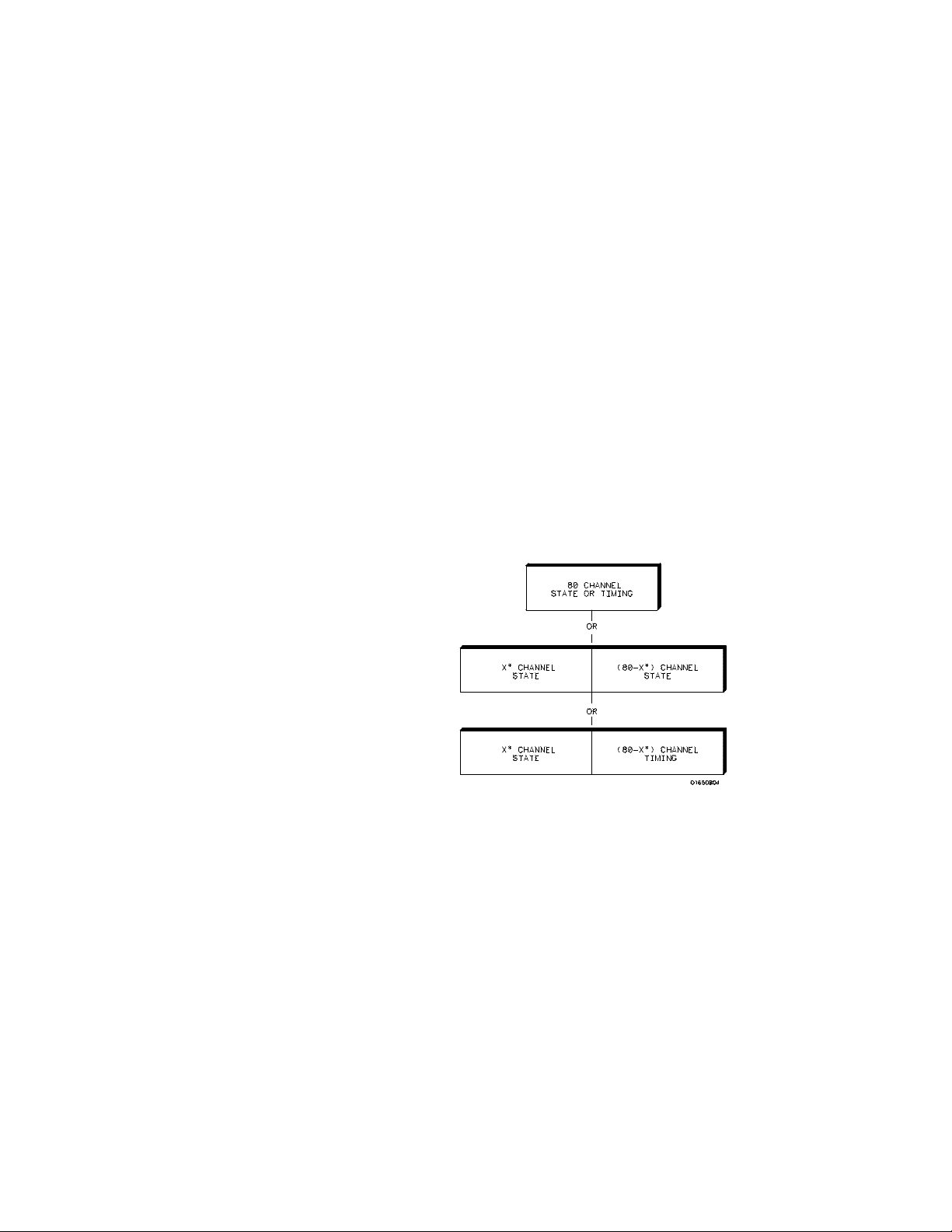
* multiples of 16 channels
The HP 16510B can be configured as two independent machines
(analyzers) maximum at one time or two mac hinesinteractively. The
combinations are:
• Up to 80 channels state
• Up to 80 channels timing
• Two state machines with multiples of 16 channels per machine with
a combined maximum of 80 channels
• One state and one timing machine with multiples of 16 channels p er
machine with a combined maximum of 80 channels
Figure 1-2. HP 16510B Configuration Capabilities
General Information HP 16510B
1 - 2 Front-panel Reference
Page 17

Key Features Two 3.5-inch disk drives are integral to the instrument for storing logic
analyzer configurations and acquired data. Thedisk drive also provides a
way of loading inverse assembly configuration files into the logic analyzer
for configuring ease.
Additional key features of both models include:
• Transitional timing for extended timing analyzer memory
• Lightweight passive probes for easy hook-up
• All channels can beused for state or timing at the maximum sample
rate
• HP-IB and RS-232C interface for programming and printer dumps
• An external trigger BNC connector
• Efficient package size
• Transitional or glitch timing m odes
• 1k-deepmemoryonallchannels
• Glitch detection
• Marker measurements
• Triggering and pattern qualification
• Overlapping of timing waveforms
• Eight sequence levels
• Eight pattern recognizers
• One range recognizer
• Time and number-of-states tagging
• Pre-store
• Auto-scale
• Programmability
• Cross-domain triggering
• Interactive measurements
• Mixed-mode display
• Oscilloscope type controls in the timing analyzer
• State Compare, Chart, and Waveform displays
Accessories
Supplied
Table 1 lists the a ccessories supplied with your HP16510B. If any of these
accessorieswere missing when you received the logic analyzer from the
factory, contact your nearest Hewlett-Packard office. If you need
additional accessories, refer to the Accessories for the HP 1650A/HP
1651A and HP 16500A Logic Analyzers data sheet.
HP 16510B General Information
Front-panel Reference 1 - 3
Page 18

Table 1-3. Accessories
Accessory HP Part No. Quantity
Probe assemblies 01650-61608 5
Probe cables (35MHz State) 16510-61601 3
Probe cables 16510-61602 2
Grabbers (Note 1) 5959-0288 100
Ground leads (long) 01650-82102 5
Ground leads (short) 01650-82103 10
RS-232C Loop back adapter 01650-63202 1
Probe a nd probe c able numbering
label card
Operating system disk 16510-13520 2
Front-panel Reference manual 16510-90913 1
Programming Reference manual 16510-90914 1
Service manual 16510-90912 1
Notes:
01650-94303 1
1. Package of 20 per part number.
Available
Accessories
General Information HP 16510B
1 - 4 Front-panel Reference
In addition to the accessories supplied, there are a number of accessories
available that will make your measurement tasks easier and more accurate.
You will find these listed in the Accessories for the HP 1650A/HP 1651A
and HP 16510A Logic Analyzers.
Page 19

Probing
Introduction This chapter contains a description of the probing system of the
HP 16510B logic analyzer. It also contains the information you need to
connect the probe system components to eachother, to the logic analyzer,
andtothesystemundertest.
2
Probing
Options
You can connect the HP 16510Blogic analyzersto your system under test
in one offour ways:
• HP 10320C User-definable Interface(optional)
• HP 10269C with microprocessor specific modules (optional)
• the standard HP 16510B probes (general purpose probing)
• direct connection to a 20-pin 3M
using the optional termination adapter (HP Part No. 01650-63201).
The optional HP 10320C User-definable Interface module combined with
the HP 10269C General Purpose Probe Interface (optional) allows you to
connect the HP 16510B logic analyzer to your target system. The HP
10320C includes a breadboard (HP 64651B) which you customwire for
your system.
Also available as an option that you can use with the HP 10320C is the HP
10321A Microprocessor Interface Kit. This kit includes sockets, bypass
capacitors, a fuse for powerdistribution, and wire-wrap headers to
simplify wiring of your interfacewhen you need active devices to support
the connection requirements of your system.
Series type header connector
HP 16510B Probing
Front-panel Reference 2 - 1
Page 20
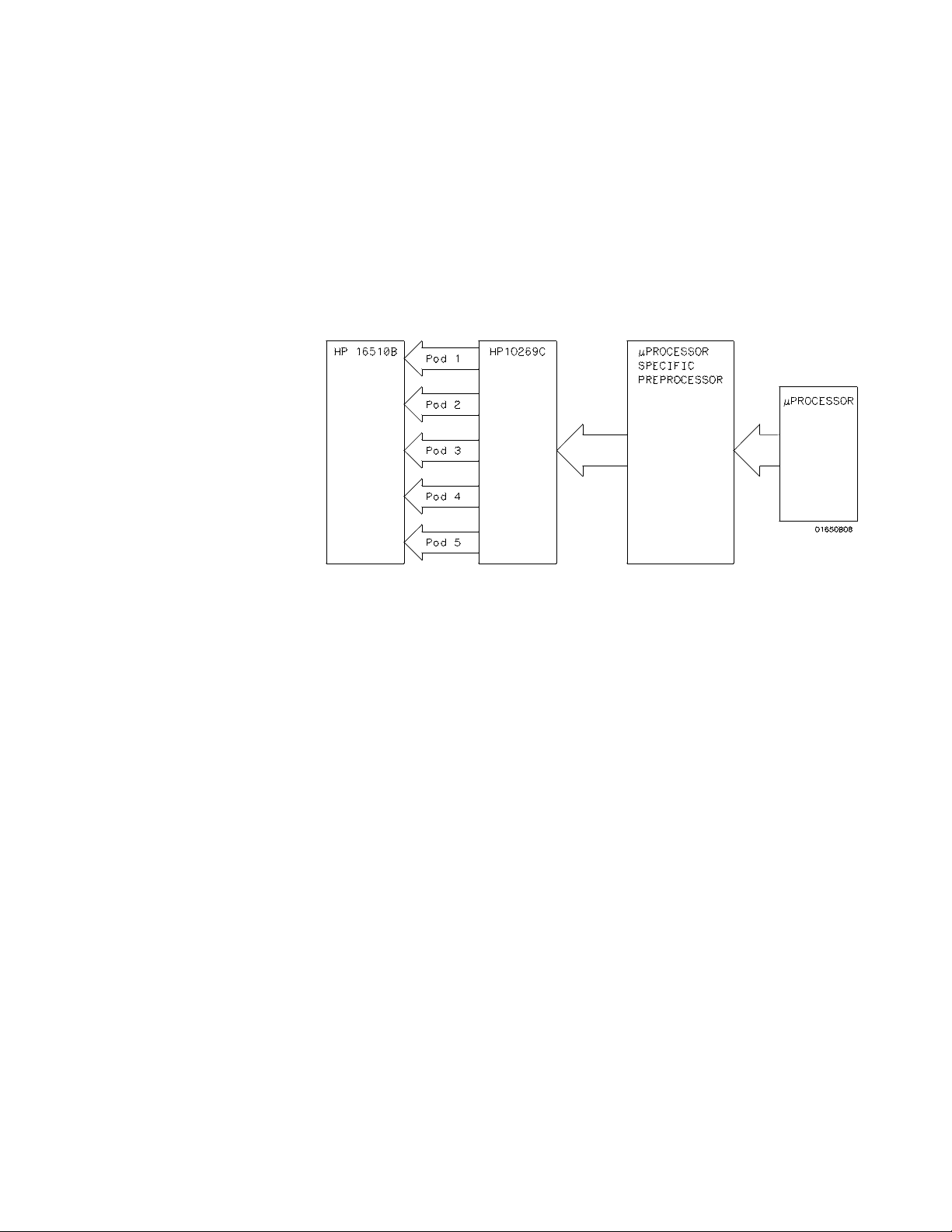
The HP 10269C
General Purpose
Probe Interface
Instead of connecting the probe tips directly to the signal lines, you may
use the HP 10269C General Purpose Probe Interface (optional). This
allows you to connect the probecables (without the probes) to connectors
on the interface. When the appropriate preprocessor is installed in the
interface, you will have a direct connection between the logic analyzer and
the microprocessor under test.
There are a number of microprocessor specific preprocessors available as
optional accessories which are listed in the Accessories for the
HP 1650/HP1651A and HP 16500A Logic Analyzers data sheet. Chapter
11 of thismanual also introduces you to preprocessors and inverse
assemblers.
Figure 2-1. HP 10269C with Preprocessor
Probing HP 16510B
2 - 2 Front-panel Reference
Page 21

General Purpose
Probing
General purpose probing involves connecting the probes directly to your
target system without using the interface. General purpose probing does
not limit you to specific hook-up schemes as the probe interface does.
The Termination
Adapter
The optional termination adapter (HP Part No. 01650-63201) allows you
to connect the probe cables directly to test ports on your target system
without the probes. However, since the probes contain the proper
termination for the logic analyzer inputs, a termination must be provided
when you aren’t using the probes. The termination adapter provides this
termination.
The termination adapter is designed to connect to a 20 (2x10) position,
4-wall, low profile header connector, 3M
You connect the termination adapter to the probe cable in place of thepod
connector and connect the other end of the adapter directly to your test
port.
Series 3592 or equivalent.
Figure 2-2. Termination Adapter
HP 16510B Probing
Front-panel Reference 2 - 3
Page 22
The HP 16510B
Probing System
The standard HP 16510B probing system consists of probes, pods, probe
cable and grabbers. This system is passive (ha s no active circuits at the
outer end of the cable). This means that the pods and probes are smaller
and lighter, making them easierto use.
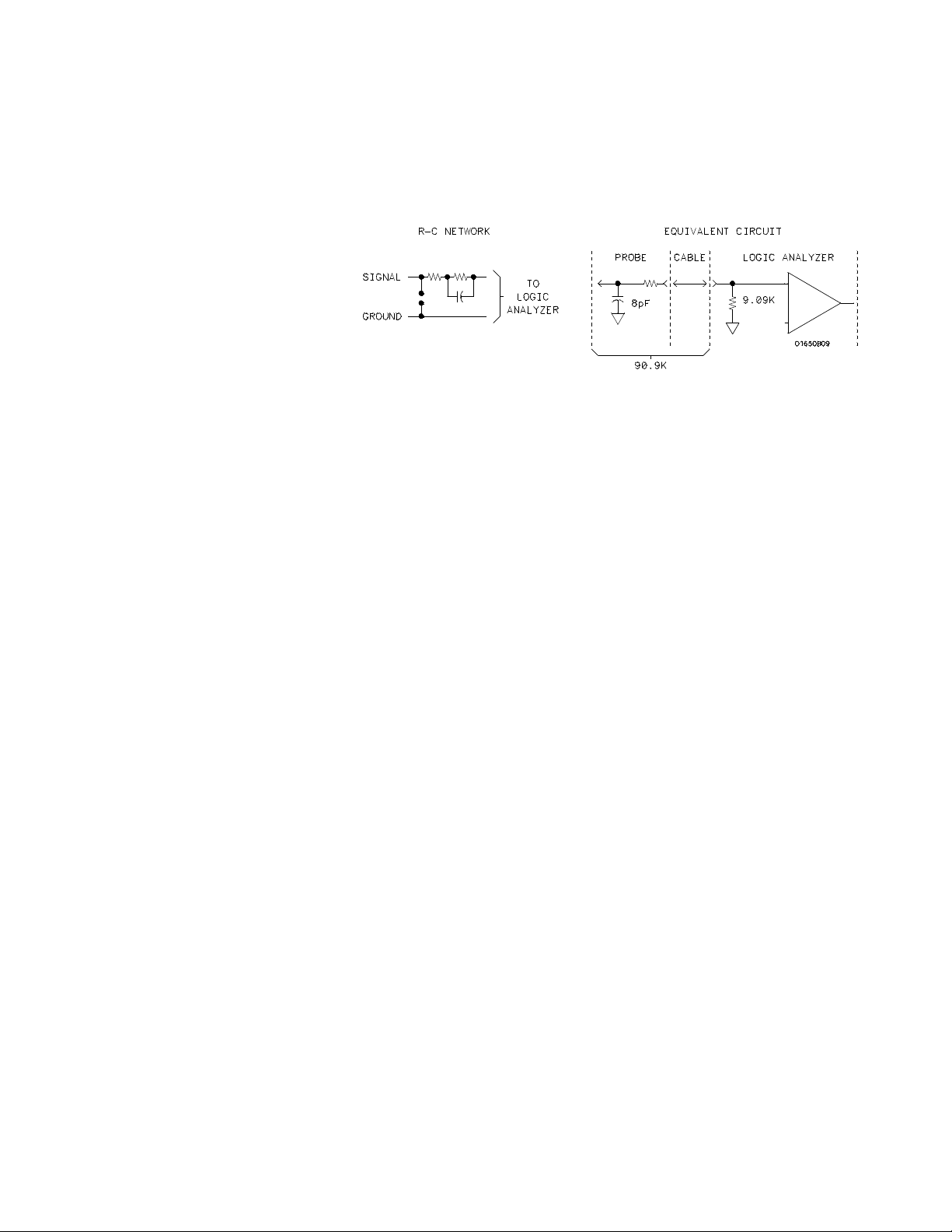
The passive probe system is similar to the probe system used with high
frequency oscilloscopes. It consists of a series R-C network (90.9 kΩin
parallel with 8 pF) at the probe tip, and a shielded resistive transmission
line.
The advantages of this system are:
• 2 ns risetime with ± 5% perturbations
• 8 pF inputcapacitance at the probetip
• signal ground at the probe tip for higher speed timing signals
• inexpensive removable probe tip assemblies
Probes and Probe
Pods
Probe Pod
Assembly
Probing HP 16510B
2 - 4 Front-panel Reference
Probes and probe pods allow you to connect the logic analyzer to your
system under test without the HP 10269C Probe Interface. This general
purpose probing is useful for discrete digital circuits. Each probe and pod
assembly contains 16 data channels, one clock channel, and pod ground.
The pods, as they will be referred to for consistency, are the probe
housings (as shown below) that group 16 data, one clock line, and
grounds, corresponding to a logic analyzer pod.
Figure 2-3. Probe Assembly
Page 23

Probe Cable The probe pod cable contains 17 signal lines, 34 chassis ground lines and
two power lines that is woven together. It is 4.5 feet long.
Caution The probe grounds are chassis (earth) grounds, not "floating" grounds.
Each cable is capable of carrying 0.67 amps for preprocessor power.
Current in excess of 0.67 amps per cable will cause the preprocessor
supply voltage to drop below a safe level. DO NOT exceed this 0.67 amps
per cable or thepreprocessor may malfunction. Also, the maximum power
available from the logic analyzer (all cables) is 2 amps at 5 volts.
Note The preprocessor power source is fused. The fuse is located inside the HP
16500A on the logic analyzer card. If a preprocessor appears to be
malfunctioning, refer to the HP 16510B service manual for instructions on
checking this fuse.
The probe cable connects the logic analyzer to thepods, termination
adapter, or the HP 10269C General Purpose Probe Interface.
Probes Each probe is a 12-inch twisted pair cable andis connected to the probe
cable at the pod. One end of each probe has a probetip assembly where
the input R-C network is housed and a lead that connects to the target
system. The other end of the probe has a two-pin connector that connects
to the probe cable.
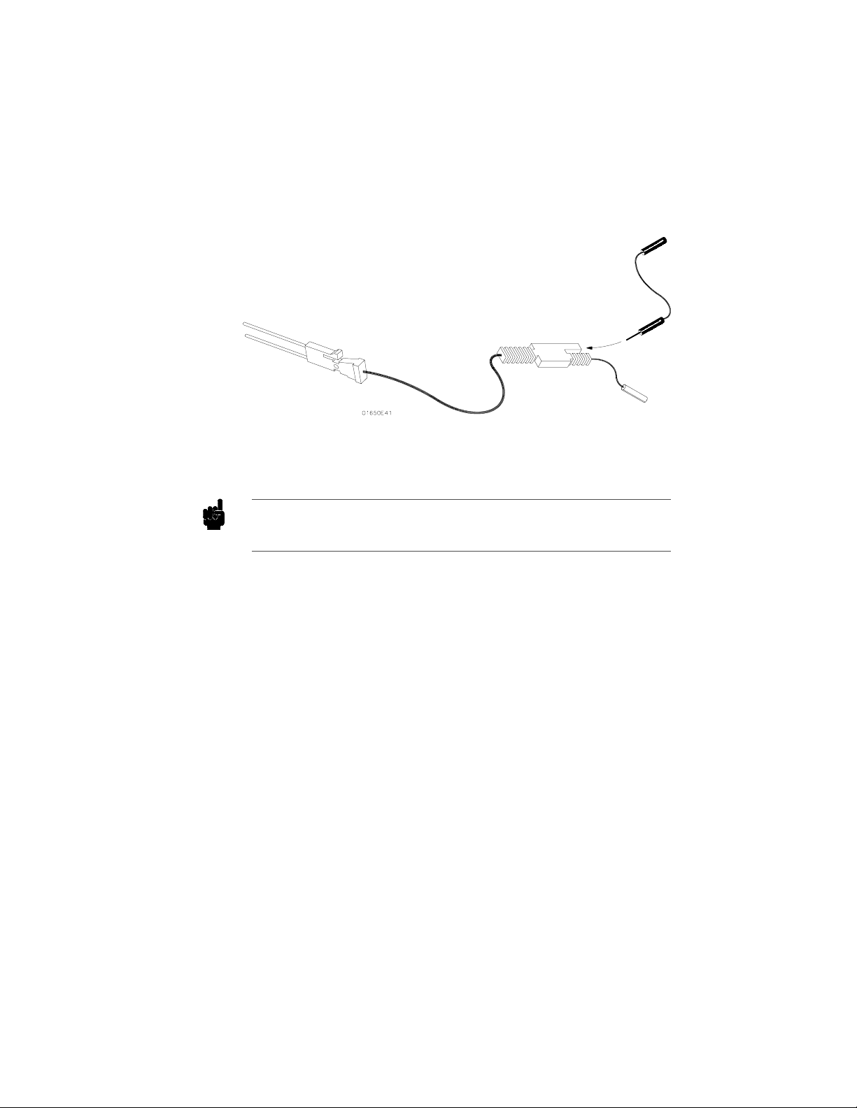
Figure 2-4. Probe Cable
HP 16510B Probing
Front-panel Reference 2 - 5
Page 24
You can connect the probe directly to the test pins on your target system.
To do so, the pins must be 0.63 mm (0.025 in.) square pins or round pins
with a diameter of between 0.66 mm (0.026 in.) and 0.84 mm (0.33 in.).
Each probe has an input impedance of 100 kΩ in parallel with
approximately 8 pF.
Figure 2-5. Probe Input Circuit
Probescanbegroundedinoneoftwoways:acommonpodgroundanda
probe ground for each probe.
Grabbers The grabbers have a hook that fits around IC pins and component leads
and connects to the probes and the ground leads. The grabbers have been
designed to fit on adjacent IC pins.
Pod Grounds Eachpodisgroundedbyapodgroundleadthatshouldalwaysbeused.
You can connect the ground lead directly to a ground pin on your target
system or use a grabber. The grabber connects to the ground lead the same
way it connects to the probe lead.
To connect the ground lead to grounded pins on your target system, the
pins must be 0.63 mm (0.025 in.) square pins or round pins with a
diameter of 0.66 mm(0.026 in.) to 0.84 (0.033 in.).
Probing HP 16510B
2 - 6 Front-panel Reference
Page 25
Probe Grounds You can ground the probes in one of two ways. You can ground the
probes with the pod ground only; however, the ground path won’t be the
same length as the signal path through the probe. If your probe ground
path must be the same as your signal path, use the short ground lead
(probe ground). The probe ground lead connects to the molded probe body
via a pin and socket. You can then use a grabber or grounded pins on your
target system thesame way as the pod ground.
Figure 2-6. Probe Grounds
Note For improved signal fidelity, use a probe ground for every four probes in
addition to the pod ground.
If you need additional probe ground leads, order HP part number
01650-82103 from your nearest Hewlett-Packard sales office.
HP 16510B Probing
Front-panel Reference 2 - 7
Page 26

Signal Line
Loading
Any signal line you intend to probe must be able to supply a minimum of
600 mV tothe probe tip, which has an input impedance of 100 kΩ shunted
by 8 pF. If the signal line is incapable of this, you will not only have an
incorrect measurement but the system under test may also malfunction.
Maximum Probe
The maximum input voltage of each probe is ± 40 volts peak.
Input Voltage
Pod Thresholds There are two preset thresholds and a user-definable pod threshold for
each pod. The two preset thresholds are ECL (−1.3 V) and TTL
(+1.6 V). The user-definablethreshold can beset anywhere between
−9.9 volts and + 9.9 volts in 0.1 volt increments.
The pod thresholds of pods 1, 2, and 3 can be set independently. The pod
thresholds of pods 4 and 5 are slaved together; therefore, when you set the
threshold o n either pod 4 or 5, both thresholds will be the same.
Connecting the
Logic Analyzer
to the Target
System
There are four ways you can connect the logic analyzer to your target
system as previously mentioned at the beginning of this chapter: the
probes (general purpose probing); the HP 10320CUser-definable
Interface; the HP 10269C with microprocessor specific preprocessor
modules; and direct connection to a20 pin 3M
connector using the optional termination adapter (HP Part No.
01650-63201).
Since the probe interface hook-ups are microprocessor specific, they will
be explained in their respective operating notes. The rest of this chapter
is dedicated to general purpose probing with the HP 16510B probes.
Series type header
Probing HP 16510B
2 - 8 Front-panel Reference
Page 27

Connecting the
Probe Cables
to the Logic
Analyzer
The probe cables are installed in the Logic Analyzer module at the factory.
The cable for pod 1 is the far left cable (rear view). Cables 2 through 5
follow cable 1 consecutively from left to right. If there is a need to install
or replace the cables refer the HP 16510B Service Manual.
Connecting the
Pods to the
Probe Cable
The pods of the HP 16510B differ from other logic analyzers in that they
are passive (have no active circuits at the outer end of the cable). The
pods, as they will be referred to for consistency, are the connector bodies
(as shown below) that the probes are installed in when you receive your
logic analyzer.
Figure 2-7. Connecting Pods to Probe Cables
Toconnectapodtoacable,youalignthekeyonthecableconnectorwith
the slot on the pod connector and push themtogether.
HP 16510B Probing
Front-panel Reference 2 - 9
Page 28
Disconnecting
the Probes
from the Pods
The probes are shipped already installed in the pods. However, you can
disconnect any un-used probes from any of the pods. This keeps the
un-used probes from getting in your way.
To disconnect a probe, insert the tip of a ball-point pen in the latch
opening and push while gently pulling the probe out of the pod connector
as shown below.
Figure 2-8. Disconnecting Probes from Pods
You connect the probes to the pods by inserting the double pin end of the
probe into the pod.The probes and pod connector body are both keyed
(beveled) so that they will fit together only one way.
Probing HP 16510B
2 - 10 Front-panel Reference
Page 29
Connecting the
Grabbers to the
Probes
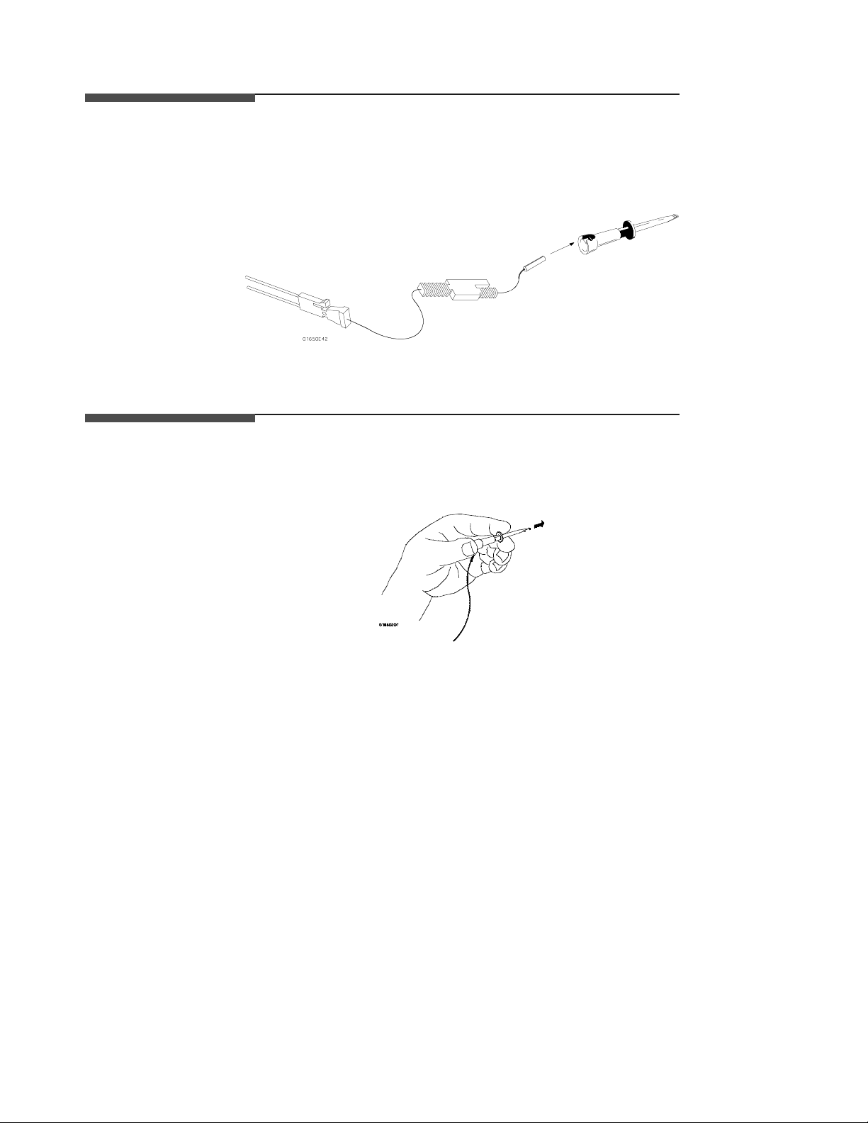
You connect the grabbers to the probes by slipping the connector at the
end of the probe onto the recessed pin in the side of the grabber. If you
need to use grabbers for either the podor the probe grounds, connect them
to the ground leads the same way you connect them to the probes.
Figure 2-9. Connecting Grabbers to Probes
Connecting the
Grabbers to the
The grabbers have a hook that fits around IC pins and component leads.
You connect the grabber by pushing therear of the grabber to exposethe
hook, hooking the lead and releasingyour thumb as shown below.
Test Points
Figure 2-10. Connecting Grabbers to Test Points
HP 16510B Probing
Front-panel Reference 2 - 11
Page 30

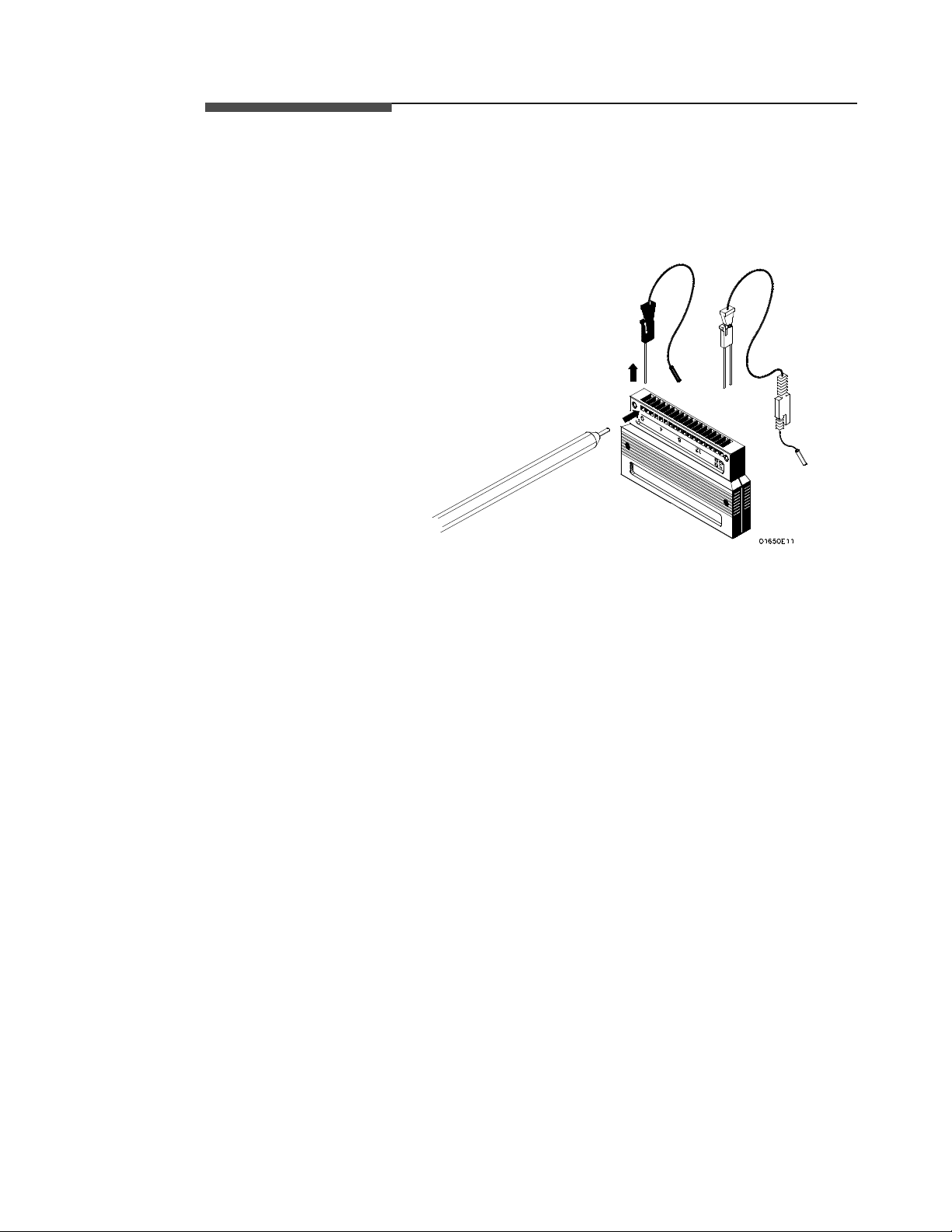
Labeling Pods,
Probes, and
Cables
So you can find the pods and probes you want to connect to your target
system, you need to be able to quickly identify them. Included with your
logic analyzer are self-adhesive labels for each pod, cable and probe.
They come in sets. Each set has labels for the end of the cable-- a label for
the pod connector body, a label for the clock probe and 16 labels for each
of the channels.
One e nd of each cable is already connected to the HP 16510B logic
analyzer module. The cable for pod 1 is the far left cable (rear view).
Cables2through5followcable1consecutivelyfromlefttoright.
Figure 2-11. Labeling Pods, Probes, and Cables
Probing HP 16510B
2 - 12 Front-panel Reference
Page 31

3
Using the Front-Panel Interface
Introduction This chapter gives you an overview of how to use the front-panel interface.
The front-panel user interface is merely accessing themany menus and
using the convenient touch-screen to move around the menu tree. The
front panel itself consists of a disk drive, the knob, power switch, display,
and receptacle for connecting the optional mouse.
The user interface allows you to configure the logic analyzer and each
analyzer (machine) within the logic analyzer. It also displays acquired
data and measurement results.
Using the front-panel interface is a basic process of:
• Selecting the desired menu
• Selecting a desired field within a menu
• Displaying the options or current variable data associated with the
desired field
• Selecting the desired option or entering new data (editing current
data) in the field
• Starting and Stopping data acquisition when the logic analyzer is
connected and configured
Using the
Mouse
HP 16510B Using the Front-Panel Interface
Front-Panel Reference 3-1
Everything that can be done with the touch screen and knob on the
HP 16500A can also be done with the optional mouse. The mouse plugs
into the connector in the lower right of the front panel. As soon as the
mouse is plugged in, it is active.
When the mouse is plugged in, a white cursor (cross) appears on the
screen. Moving the mouse causes the cursor to move. To "touch" a field
with the mouse, move the cursor to the field and press the left button on
the mouse.
To use the mouse to perform the functions of the front-panel knob, hold
down the right button and move the mouse. When you release this button,
the function returns to the cursor.
Page 32

How to
Select Menus
Note The field containing State/Timing (x) may have a different letter
Before you try to select one of the main menus, make sure the field in the
upper left-hand corner is set to State/Timing E. If the HP 16500A is in
System or Intermodule, touch that field and select State/Timing E when
the pop-up appears.
following State/Timing. Don’t be alarmed. This letter merely tells you
what card slot the State/Timing module is in.
To select the main menus touch the second field from the left at the top of
the screen. A pop-up appears showing you the active menus. The menus
are:
• Configuration
• Format 1, 2, or both
• Trace1,2,orboth
• Waveform (Timing analyzer only)
• Listing (State analyzer only)
When the menu is displayed you c an access the fields within the menus.
The second field from the left in the upper left-hand corner always
displays the current menu. To move around in the menu tree, you must
always touch the field displaying the current menu and select a new menu
when the pop-up appears.
The Configuration, Format, Trace, Waveform, and Listing menu fields
provide access to their respective menus. All menus, subsystems, and
fields in the entire logic analyzer are pop-ups that appear on top of the
currently displayed menu.
If more than one analyzer (machine) is on, you see the selected menu of
either analyzer 1 or analyzer 2 depending on what analyzer menu was
last displayed or what you did in the State/Timing E Configuration
menu.
To switch from one of these menus to another menu within the same
analyzer (machine) touch the current field (i.e. Waveform), which is
displayed in the field second from the left in the upper left corner and
make a new selection.
Using the Front-Panel Interface HP 16510B
3-2 Front-Panel Reference
Page 33

How to Switch
Between
Analyzers
You can switch between analyzers in any main menu by touching the field
(second from the left in the upper left-hand corner). When the pop-up
appearsyoucanselectthedesiredmenuinthedesiredanalyzerwhenboth
analyzers are on. One example of the options available when both
analyzers (one state and one timing) are on are:
• Format 1
• Format 2
• Trace 1
• Trace 2
• Waveform (for Timing analyzer)
• Listing (for State analyzer)
Touch the field inthe pop-up to enter the desired menu. You will
immediatelygotothatmenu.
Returning to
the System
Configuration
Menu
You can return to the System Configuration menu from any main logic
analyzer menu. To return to the System Configuration menu. touch
State/Timing E. When the pop-up appears, touch System. Whenthe
pop-up closes, System will be displayed in the upper left corner. If
Configuration is not displayed in the field second from the left in the
upper left corner, touch this field. When the pop-upappears,touch
Configuration. You will now be in the System Configuration menu.
Pop-up Menus The pop-up menu is used exclusively in this logic analyzer. This gives you
more flexibility to move through the menu tree and faster access to the
individual subsystems.
To use the pop-ups when they appear, simply touch the field in the pop-up
you want. The pop-up will immediately close and the menu you select will
appear.
HP 16510B Using the Front-Panel Interface
Front-Panel Reference 3-3
Page 34

How to Close
Pop-up Menus
Some pop-up menus automatically close when you touch a desired field.
After closing, the logic analyzer places your choice in the main menu field
from which you opened the pop-up.
Other pop-up menus don’t automaticallyclose when you make your
selection (i.e. alphanumeric keyboard). These menus have a Done option.
To close the pop-up all you haveto do is touch the Donefield.
Toggle Fields Some fields will toggle between two options (i.e.,off and on). When you
touch one of these fields, the displayed option toggles to the other choice
and no additional pop-up appears.
How to Select
Options
How to select options depends on what type of pop-up menu a ppears
when you touch the field. When the pop-up appears, you will see a list of
options. You select the option by touching the option field. In most cases
the pop-up menu closes when you touch an option and the selected option
will be displayed. However, in some pop-ups, selecting the option does
not automatically close the pop-up. In this case the option Done ispresent.
There are also pop-up menus where each option within the pop-up menu
has more than oneoption available.In these cases, when you touchthat
field, another pop-up, with options, will be superimposed on the original
pop-up.
Using the Front-Panel Interface HP 16510B
3-4 Front-Panel Reference
Page 35

Figure 3 - 1. State Clock Pop-u p Menu
An example of one of these is the clock field in the State Format
Specification menu. When you select the clock field in this menu itwill
pop-up and show you all five clocks (J, K, L, M,andN). When you select
one of the five clocks, another pop-up appears showing you the available
choices of clock specifications.
Figure 3 - 2. State Clock Pop-up with K Pop-up
HP 16510B Using the Front-Panel Interface
Front-Panel Reference 3-5
Page 36

When you touch one of these the pop-up will close, however, the original
clock pop-up still remains open. When you are finished specifying the
choices for the c locks, you close the original pop-up menu by touching
Done.
How to Enter
Numeric Data
There are a number of pop-up menus in which you enter numeric data.
The two major types are:
• Numeric entry with fixed units
• Numeric entry with variable units (i.e. µs, ms, etc.)
There are several numeric entry menus where you enter only the value, the
units being pre-determined. There are other numeric entry menus for
which you will be required to specify the units. One such type of numeric
entry pop-up that you enter the unitsis the pod threshold pop-up.
Besides being able to set the pod thresholds to either of the preset
thresholds (TTL or ECL), you can set the thresholds to a specific voltage
from −9.9 V to + 9.9V.
To set pod thresholds to a specific voltage, you enter either Format menu
and touch a pod field. When the pop-up appears you can choose TTL,
ECL,orUser.
Figure 3 - 3. Pod Threshold
Using the Front-Panel Interface HP 16510B
3-6 Front-Panel Reference
Page 37

If you select the User option, a numeric keypad pop-up appears where you
enter the desired threshold voltage. After selecting the value, you select
the units (i.e., mV or V). Touch Done when you have finished specifying
the pod threshold.
Figure 3 - 4. Numeric Entry Keypad
If you want a negative voltage for the threshold, press the − (minussign)
in the pop-up. Entering the − (minus sign) can be done either before or
after the voltage level has been entered.
How to Enter
Alpha Data
You can give specific names to several items. These names can represent
your measurement specifically. For example, you might choose the name
68000STATE for the state analyzer configuration you areusing on a
68000 microprocessormeasurement.
The two major examples of items that can be named are:
• The name of each analyzer
• Labels
• Symbols
• Filenames
• File descriptions
HP 16510B Using the Front-Panel Interface
Front-Panel Reference 3-7
Page 38

For example, you can nameeach analyzer with a name that is
representative of your measurement. The default names for the analyzers
within the logic analyzer are MACHINE 1 and MACHINE 2. To rename
an analyzer, touch the field to the right of Name:_______ in the
State/Timing E Configuration menu. When the alphanumeric pop-up
menu appears, enter the name you desire.
The line above the alphanumeric keyboard contains the current name.
When you first enter the pop-up, the cursor in the name field isat the left.
You can enter the name you wish by overwriting the existing name. If
only a few changes need to be made, you can move the cursor using the
knob to a character needing changed and select a new character. You can
also clear the entire field by touching Clear. When you have entered the
desired name, touch Doneand the pop-up will close. The new name will
appear in the field to the right of Name:________.
Figure 3 - 5. Alphanumeric Keypad
Using the Front-Panel Interface HP 16510B
3-8 Front-Panel Reference
Page 39

How to
Roll Data
The roll feature is available in all menus that contain off-screen data. This
allows you to roll data for viewing. Data can be off-screen both above and
below or left and right of what you see on screen.
One example of a menu having off-screen data above and below the
screen is the State Listing. The state listing is normally a list 1024 lines
long, however, the display is only capable of showing you 16 lines at a
time. To roll data in the state Listing (when the box in the left center of the
listing area is light blue) simply turn the knob. If this box is not light blue,
touch this box and then turn the knob. Ifyou touch this box when it is
light blue, a keypad will appear with which you can enter a state location.
This allows you to effectively roll the displayed listing in large increments.
Figure 3 - 6. State Listing Menu with Off-screen
HP 16510B Using the Front-Panel Interface
Front-Panel Reference 3-9
Page 40

An example ofoff-screen data left and right can also be shown in figures
3-7 and 3-8. Figure 3-7 illustrates a timing Trace menu with labels off
screen. In this case only six of the eight labels can be displayed at a time.
Whenever there is data off screen to the left or right, an additional field
exists in the menu as shown in figure 3-7. This is called a field because it
is enclosed in a box and will turn light blue when touched.
Figure 3 - 7. Off-screen Data Indicator
If data does not exist off screen, the term Label > will not be enclosed in a
box (see figure 3-8).
Figure 3 - 8. No Off-screen Data Left or Right
Using the Front-Panel Interface HP 16510B
3-10 Front-Panel Reference
Page 41

Assignment/
Specification
Menus
There are a number of pop-up menus in which you can assign or specify
what you want the logic analyzer to do. The basic menus of this type
consist of:
• Assigning bits to pods
• Specifying patterns
• Specifyingedges
Assigning Pod
Bits to Labels
The bit assignment fields in both state and timing analyzers work
identically. The convention for bit assignment is:
* (asterisk) indicates assigned bits
. (period) indicates un-assigned bits.
An example of assigning bits is in either the Timing or State Format menu.
Note If you don’tsee any bit assignment fields, it merely means you don’thave
any pods assigned to this analyze r. Either switch analyzers or assign a pod
to the analyzer you are working with.
Figure 3 - 9. Bit Assignment Pop-up Menu
HP 16510B Using the Front-Panel Interface
Front-Panel Reference 3-11
Page 42

To assign bits to eitherAnalyzer 1 or Analyzer 2 there must b eat least one
pod assigned to the desired analyzer. If there are no pods assigned to the
analyzer you wish to use follow steps 1 and 2. If there is a pod assigned to
the desired analyzer go to step 3 where you access the Format menu.
1. Enter the State/Timing E Configuration menu.
2. Touch a Pod field. When the pop-up appears, assign the pod to the
analyzer of your choice.
3.Touchthefieldsecondfromleftinthetopleftcorner.Whenthe
pop-up appears, touch Format 1 (or 2).
4. Before you can select a bit pattern at least one label must beon. To
turn a labelon, touch the labelfield and when the pop-up appears,
touch Turn Label On.
5. Touch the bit assignemnt field to access the bit assignment pop-up.
6. When the pop-up appears, using the KNOB, place the cursor on the
desired bit and touch the asterisk to assign a bit or the per iod to
unassign a bit. Touch Done when bit assignment is complete.
When the pop-up closes the bit assignment field is again displayed,
however, now it is displaye dwith the assigned pattern.
Using the Front-Panel Interface HP 16510B
3-12 Front-Panel Reference
Page 43

Specifying
Patterns
The Pattern field appears in several menus. Patterns can be specified in
one of theavailablenumber bases. Patterns can be viewed in ASCII,but
cannot be entered in ASCII.
The convention for "don’t care" in these menus is an X except in the
decimal base. If the base is set to decimal after a "don’t care" is specified,
a $ will be displayed.
To select a pattern, enter the Trace menu and follow these steps:
1. Touch the field to the right of Pattern. You willsee a keypad pop-up
(see figure 3-10).
Figure 3 - 10. Specifying Patterns Keypad Pop-up
Menu
2. Using the alphanumeric keyboard, enter the desired pattern.
Note The Base > field and the Find Pattern field are interactive. Only a keypad
that is compatible with the selected base will appear when the pop-up
opens. Since ASCII patterns cannot be entered directly, a keypad will not
appear for data entry if the base isset to ASCII.
When the pop-up is open, you enter your desired pattern from the keypad
(including don’t cares). When you finish entering your pattern, close the
pop-up by touching Done.
HP 16510B Using the Front-Panel Interface
Front-Panel Reference 3-13
Page 44

Specifying Edges
You can select a positve-going (↑), negative-going (↓), and either edge ( )
foryourtrigger.
To specify edges, enter the Trace menu and follow these steps:
1. Touch the field in the bottom left corner of the display. This field is
labeled Edge. You will see the following pop-up.
Figure 3 - 11. Specifying Edges Pop-up Menu
2. When the pop-up appears you can make your edge selection for any
bit by placing the cursor, using the KNOB, on the desired bit and
touching the period, either edge, or both edges field.
3. After you have made your edge selection, touch Done.
Note When you close the pop-up after specifying edges, you will see dollar
signs ($$..)intheThen find Edge field if the logic analyzer can’t display
the edge correctly. This indicates the logic analyzer can’t display thedata
correctly in the number base you have selected.
Using the Front-Panel Interface HP 16510B
3-14 Front-Panel Reference
Page 45

4
Using the Menus
Introduction This chapter contains menu maps ofthe HP 16510B logic analyzer. Since
the front-panel user interface consists mainly of menus that you access to
configure the logic analyzer, the menu maps provide quick reference to the
menus, menu options, and ultimately the functions of the logic analyzer.
Menu Maps The following pages show the menu maps of all functions of the logic
analyzer. The State/Timing Configuration menu is the logic analyzer’s
system level menu. The rest of the menus are the subsystem level menus
of the logic analyzer.
HP 16510B Using the Menus
Front-Panel Reference 4 - 1
Page 46

State/Timing
Configuration
Menu Map
Figure 4-1. State/Timing Configuration Menu
Using the Menus HP 16510B
4 - 2 Front-panel Reference
Page 47

Timing Format
Menu Map
Figure 4-2. Timing Format Menu Map
HP 16510B Using the Menus
Front-Panel Reference 4 - 3
Page 48

Timing Trace
Menu Map
Figure 4-3. Timing Trace Menu Map
Using the Menus HP 16510B
4 - 4 Front-panel Reference
Page 49

Timing
Waveform
Menu Map
Figure 4-4. Timing Waveform Menu Map
HP 16510B Using the Menus
Front-Panel Reference 4 - 5
Page 50

Figure 4-4. Timing Waveform Menu Map (continued)
Using the Menus HP 16510B
4 - 6 Front-panel Reference
Page 51

State Format
Menu Map
Figure 4-5. State Format Menu Map
HP 16510B Using the Menus
Front-Panel Reference 4 - 7
Page 52

State Trace
Menu Map
Figure 4-6. State Trace Menu Map
Using the Menus HP 16510B
4 - 8 Front-panel Reference
Page 53

Figure 4-6. State Trace Menu Map (continued)
HP 16510B Using the Menus
Front-Panel Reference 4 - 9
Page 54

State Listing
Menu Map
Figure 7-4. State Listing Menu Map
Using the Menus HP 16510B
4 - 10 Front-panel Reference
Page 55

State Compare
Menu Map
Figure 4-8. State Compare Menu Map
HP 16510B Using the Menus
Front-Panel Reference 4 - 11
Page 56

State Waveform
Menu Map
Figure 4-9. State Waveform Menu Map
Using the Menus HP 16510B
4 - 12 Front-panel Reference
Page 57

Figure 4-9. State Waveform Menu Map (continued)
HP 16510B Using the Menus
Front-Panel Reference 4 - 13
Page 58

State Chart
Menu Map
Figure 4-10. State Chart Menu Map
Using the Menus HP 16510B
4 - 14 Front-panel Reference
Page 59

Figure 4-10. State Chart Menu Map (continued)
HP 16510B Using the Menus
Front-Panel Reference 4 - 15
Page 60

Mixed Display
Menu Map
Figure 4-11. Mixed Display Menu Map
Using the Menus HP 16510B
4 - 16 Front-panel Reference
Page 61

Menus
Introduction This chapter describes the menus and pop-up menus that you will use on
your logic analyzer. The purpose and functions of each menu are
explained in detail, and we have included many illustrations and examples
to make the explanations clearer.
The main menus of the logic analyzer are grouped into two categories:
System Level Menus and Subsystem Level Menus. The System Level
Menu is:
• State/Timing Configuration Menu
The Subsystem Level Menus are:
• Format (timing and state)
• Trace (timing and state)
• Timing Waveforms
• State Listing
An illustration of each main menu is given at the beginning of the section
that describes the menu. In the illustration, the fields arenumbered
accordingtotheorderinwhichtheyarediscussedtomakethemeasyto
reference.
5
System Level
Menu
HP 16510B Menus
Front-Panel Reference 5-1
When the logic analyzer is selected from the System Configuration menu,
the State/Timing Configuration menu is displayed. It is in this menu that
you configure your logic analyzer in one of four ways: timing analyzer
only, state analyzer only, two state analyzers, or one timing analyzer and
one state analyzer. You can also name each internal analyzer and assign
pods to them.
Page 62
State/Timing
Configuration
Menu
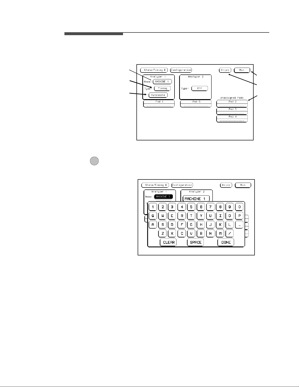
The State/Timing Configuration menu for the HP 16510B Logic Analyzer
is shown below. The fields in the menu that are numbered in the figure are
describedin this section.
1
2
6
5
3
Figure 5-1. State/Timing Configuration Menu
1NameYounameananalyzerbyselectingtheNamefieldunderit.An
alphanumeric pop-up menu will appear. The keypad is similar to a
computer keyboard.
4
Figure 5-2. Alphanumeric Keypad Pop-up
Menus HP 16510B
5-2 Front-Panel Reference
Page 63

Atthetopofthekeypadpop-up,isaboxwherethecurrentnameappears
when the pop-up opens, and where the new name will appear when you
touchkeysonthekeypad.Inthenameboxisacursorwhichindicatesin
what space your next selection will be placed.
You can name the analyzer in one of two ways. The first way is to
position the cursor over the character to be replaced in the pop-up using
the KNOB, then touching the new character. The new character appears in
thenamebox.
The second way is to touch CLEAR. Thisclears the entire name from the
box and places the cursor at the beginning of the name box in the pop-up.
When you have entered the correct name, touch DONE.
2TypeThe Type field defines the machine as either a state analyzer or a timing
analyzer or indicates that a system performance analysis (SPA) can be
done on that analyzer (optional). When this field is touched, a pop-up
menu appears. You touch themachinetype to make your selection.
Figure 5-3. Type Pop-up Menu
HP 16510B Menus
Front-Panel Reference 5-3
Page 64

3 Autoscale The purpose of Autoscaleis to provide a starting point for setting up a
measurement. The Autoscale field only appears on a timing analyzer.
When you touch Autoscale, you will see a pop-up with two options:
Cancel and Execute. If you select Cancel, the autoscale is cancelled and
control is returned to the State/Timing Configuration menu.
Figure 5-4. Autoscale Pop-up Menu
If you choose Execute, autoscale configures the timing Format and Trace
Specification menus and the timing Waveforms menu. Any configurations
that you have done will be lost. Autoscale searches for channels with
activity on the pods assigned to the timing analyzer and displays them in
the Waveforms menu.
Note Executing autoscale erases all previous configurations for your timing
analyzer and turns the other analyzer off. If you don’t want this to happen,
touch Cancel in the pop-up.
Menus HP 16510B
5-4 Front-Panel Reference
Page 65

4 Pods Each pod can be assigned to one of the analyzers. When the HP 16510B
Logic Analyzer is powered up, Pod 1 is assigned to Analyzer 1 and Pod 5
is assigned to Analyzer 2.
To assign a pod,touch the pod field. With the pop-up that appears, you
can assign the pod to Analyzer 1, Analyzer 2, or Unassign it. Makinga
selection closes the pop-up and moves the pod field to the analyzer to
whichthepodisassigned.
Figure 5-5. Pod Assignment Pop-up Menu
5PrintThePrintfieldallowsyoutoprintwhatisdisplayedonthescreenatthe
time you initiate the printout. When you touch the Print field, a pop-up
appears showing you the print options Cancel, Print Screen,andinsome
menus, Print All.
You start a print by touching the Print field. When the pop-up appears,
you touch either Print Screen or Print All. The information on the screen
is frozen, and the Print field changes to Cancel and turns red. While the
data is being transferred to the printer, the logic analyzer’s user-interface
is not usable with the exception of the Cancel field. When the logic
analyzer has completed the data transfer to the printer, the advisory "Print
Completed" is displayed and the user-interface is usable again.
If you wish to stop a printout before it is completed, touch Cancel.This
stops the print, and the message "Print Cancelled" appears in red.
HP 16510B Menus
Front-Panel Reference 5-5
Page 66

Print Screen. In the Print Screen mode, the printer uses its graphics
capabilities so that the printout will look just like the logic analyze rscreen.
Print All. The Print All option prints not only what is displayed on screen
but what is below, and, in the Format Specification, what is to the right of
the screen at the time you initiate the printout.
Note Make sure the first line you wish to print is in the light blue box at the
center of the listing areawhen you touch Print All. Lines above this box
will not print.
Use this option when you want to print all the data in menus like:
• Timing Format Specifications
• State Format Specifications
• State Trace Specifications
• State Listing
• Symbols
If there is information below the screen, as in the State Listing, the
information will be printed on multiple pages. In Timing and State Format
Specifications, the print will be compressed when necessary to print data
that is off-screen to the right.
When you select the PrintAll option, the information on the screen is
frozen, and the message "Pr inting All" appears at the top of the display.
Don’t worry, this message will not appear in your printout. While the data
is being transferred to the printer, the logic analyzer’s user-interface is not
usable. When the logic analyzer has completed the data transfer to the
printer, the advisory "Print Completed" appears and the user-interface is
again usable.
Menus HP 16510B
5-6 Front-Panel Reference
Page 67

If you wish to stop a printout before it is completed, touch Cancel.This
stops the print and the message "Print Cancelled" appears at the top of the
display.
6RunThe Run field allows you to start data acquisition. The pop-up that
appears when you touch this field contains the trace mode options Single,
Repetitive,andCancel. This field is explained in detail in "Run/Trace
Mode" in both the Timing and State Trace specification menus sections of
this chapter.
Subsystem
Level Menus
The HP 16510B logic analyzer is configured for measurements in the
Timing and State Format and Trace Specification menus. The Format
menus can be accessed by touching Format 1 or 2, and the Trace menus
by touching Trace 1 or 2.
The Format Specification menus let you specify how the logic analyzer
groups the input channels from your microprocessor. You can set the
threshold levels of the pods assigned to the analyzer, assign labels and
channels, specify symbols, and, in the caseof the stateanalyzer, set clocks
for triggering.
The Trace Specification menus allow you to configure the logic analyzer
to capture only the data of interest in yourmeasurement. The logic
analyzer acquires data until it triggers at a location that you specify by
setting certain parameters for the data. In the timing analyzer y ou can
configure the analyzer to trigger on specific patterns, edges, or glitches. In
the state analyzer you can configure the analyzer to trigger on a sequence
of states.
At power up, the logic analyzer is configured with a default setting. You
can use this default setting to make a test measurement on your system. It
can give you an idea ofwhere to start your measurement.
Each of theformat and trace specification menus will be covered in this
chapter. For examples on setting up configurations for measurements with
the timing and state analyzers, refer to your HP 16510B Getting S tarted
Guide or chapters 7 through 9 in this manual.
HP 16510B Menus
Front-Panel Reference 5-7
Page 68

Format
Specification
Menus
At power up the Timing and State Format Specification menus look
basically the same, with a few exceptions in the state analyzer. The
Timing Format Specification menu looks like that shown below:
5
1
4
2
Figure 5-6. Timing Format Specification Menu
The State Format Specification menu for the HP 16510B looks like the
following:
8
3
6
7
Activity
Indicators
Figure 5-7. State Format Specification Menu
Menus HP 16510B
5-8 Front-Panel Reference
Page 69

These menus show only one pod assigned to each analyzer at powerup.
Any number of pods can be assigned to one analyzer,from none to all
five. In the Format menus, only three pods appear at a time in the display.
If there are any pods off screen, an additional field will be present. This
field is labeled Pods ↔.Toviewoff-screenpods,touchthePods ↔ field
and rotate the KNOB. The pods are always positioned so that the lowest
numbered pod is on the right and the highest numbered pod is on the left.
Timing and State
Format
Specification
Menu Fields
1LabelThe label column contains 20 Label fields that you can define. Of the 20
Seven types of fields are present in the menus. They are:
1) Label
2) Polarity (Pol)
3) Bit assignments
4) Pod threshold
5) Specify Symbols
6) Clock (state analyzer only)
7) Pod Clock (state analyzer only)
8) Clock Period (state analyzer only)
A portion of the menu that is not a f ieldis the Activity Indicators display.
The indicators appear above the bit numbers of eachpod. When the logic
analyzer is connected to your target system and the system is running, you
will see in the Activity Indicators display for each channel that has
activity. These tell you that the signals on the channels are transitioning.
The fields in the Format menus are described in the following sections.
The descriptions apply to both the timing and state analyzers unless noted
otherwise.
labels, the logic analyzer displays only 8 at one time. To view the labels
that are offscreen, rotate the KNOB. The labels roll up and down.
HP 16510B Menus
Front-Panel Reference 5-9
Page 70

To access one of the Label fields, touch the desired field. You will se ea
pop-up menu like that shown below.
Figure 5-8. Label Pop-up Menu
Turn Label On. Selecting this option turns the label on and gives it a
default letter name. If you turned all the labels on they would be named
POD 1 through T fr om top to bottom in the timing analyzerand A
through T in the state analyzer. When a label is turned on, bit assignment
fields for the label appear to theright of the label under the pods.
Modify Label. If you want to change the name of a label, or want to turn
a label on and give it a specific name, you would select the Modify Label
option. When you do, an alphanumeric keypad pop-up menu appears. You
use the pop-up keypad to name the label. A label name can be a maximum
of six characters.
Turn Label Off. Selecting this option turns the label off. When a label is
turned off, the bit assignments are saved by the logic analyzer. This gives
you the option of turning the label back on and still having the bit
assignments if you need them. The timing waveforms and state listings are
also saved.
Youcangivethesamenametoalabelinthestateanalyzerasinthe
timing analyzer without causing an error. The logic analyzer distinguishes
between them. An example of this appears in chapter 7 of the HP 16510B
Getting Started Guide and chapter 9 of this manual.
Menus HP 16510B
5-10 Front-Panel Reference
Page 71

2 Polarity (Pol) Each label has a polarity assigned to it. The default for all the labels is
positive ( + ) polarity. You can change the polarity of a label by touching
the polarity field. This toggles the polarity between positive ( + ) and
negative ( −).
In the state analyzer, negative polarity inverts all the data. In the timing
analyzer, negative polarity inverts all the data,but doesn’t change the
actual waveforms in the TimingWaveformsMenu.
3 Bit Assignment The bit assignment fields allow you to assign bits (channels) to labels.
Above each column of the bit assignment fields is a line that tells you the
bit numbers from 0 to 15, with the left bit numbered 15 and the right bit
numbered 0. This line helpsyou know exactly which bits you are
assigning.
The convention for bit assignment is:
* (asterisk) indicates assigned bit
. (period) indicates unassigned bit
At power up the 16 bits of Pod 1 are assigned to the timing analyzer, and
the 16 bits of Pod 5 are assigned to the state analyzer.
To change a bit assignment configuration, touch a bit assignment field.
You will see the following pop-up menu.
Figure 5-9. Bit Assignment Pop-up Menu
Use the KNOB to move the cursor to an asterisk or a period you wish to
change. Touch the desired state (asterisk or period) in the pop-up. When
the bits (channels) are assigned as desired, touch DONE.Thisclosesthe
pop-up and displays the newbit assignment in the Format Specification
menu.
HP 16510B Menus
Front-Panel Reference 5-11
Page 72

Assigning one channel per label may be handy in some applications. This
is illustrated in chapter 7 of the HP 16510B Getting Started Guide.Also,
you can assign a channel to more than one label, but this usually isn’t
desired.
Labels may have from 1 to 32 channels assigned to them. If you try to
assign more than 32 channels to a label, the logic analyzer will beep,
indicating an error, and amessage will appearat the top of the screen
telling you that 32 channels per label is maximum.
Channels assigned to a label are numbered from right to left by the logic
analyzer. The least significant assigned bit (LSB) on the far right is
numbered 0, the next assigned bit is numbered 1, and so on. Since the
maximum of 32 channels can be assigned to one label, the highest number
that can be given to a channel is 31. Although labels can contain split
fields, assigned channels are always numbered consecutively within a
label. The numbering of channels is illustrated with the figure below.
Bit 31
Figure 5-10. Numbering of Assigned Bits
Bit 19
Bit 8
Bit 0
4 Pod Threshold Each pod has a threshold level assigned to it. Threshold levels maybe
defined for Pods 1, 2 and 3 individually, and one threshold for Pods 4 and
5. It doesn’t matter if Pods 4 and 5are assigned to different analyzers.
Changing the threshold of either pod 4 or 5 changes the threshold of the
other.
Menus HP 16510B
5-12 Front-Panel Reference
Page 73
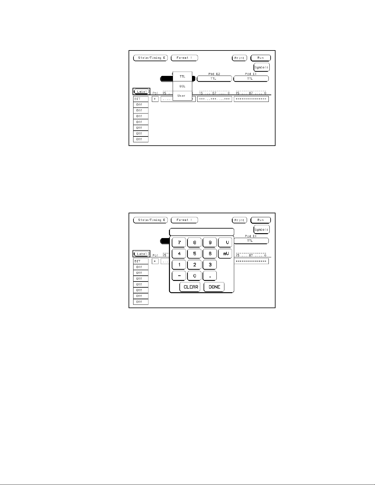
If you touch the pod threshold fields you will see the following pop-up
menu.
Figure 5-11. Pod Threshold Pop-up Menu
TTL sets the threshold at +1.6 volts, and ECL sets the threshold at −1.3
volts.
The User option lets you set the threshold to a specific voltage between
−9.9 V and +9.9 V. If you select this option you will see a numeric entry
keypad pop-up menu as shown.
Figure 5-12. Numeric Entry Keypad Pop-up Menu
HP 16510B Menus
Front-Panel Reference 5-13
Page 74
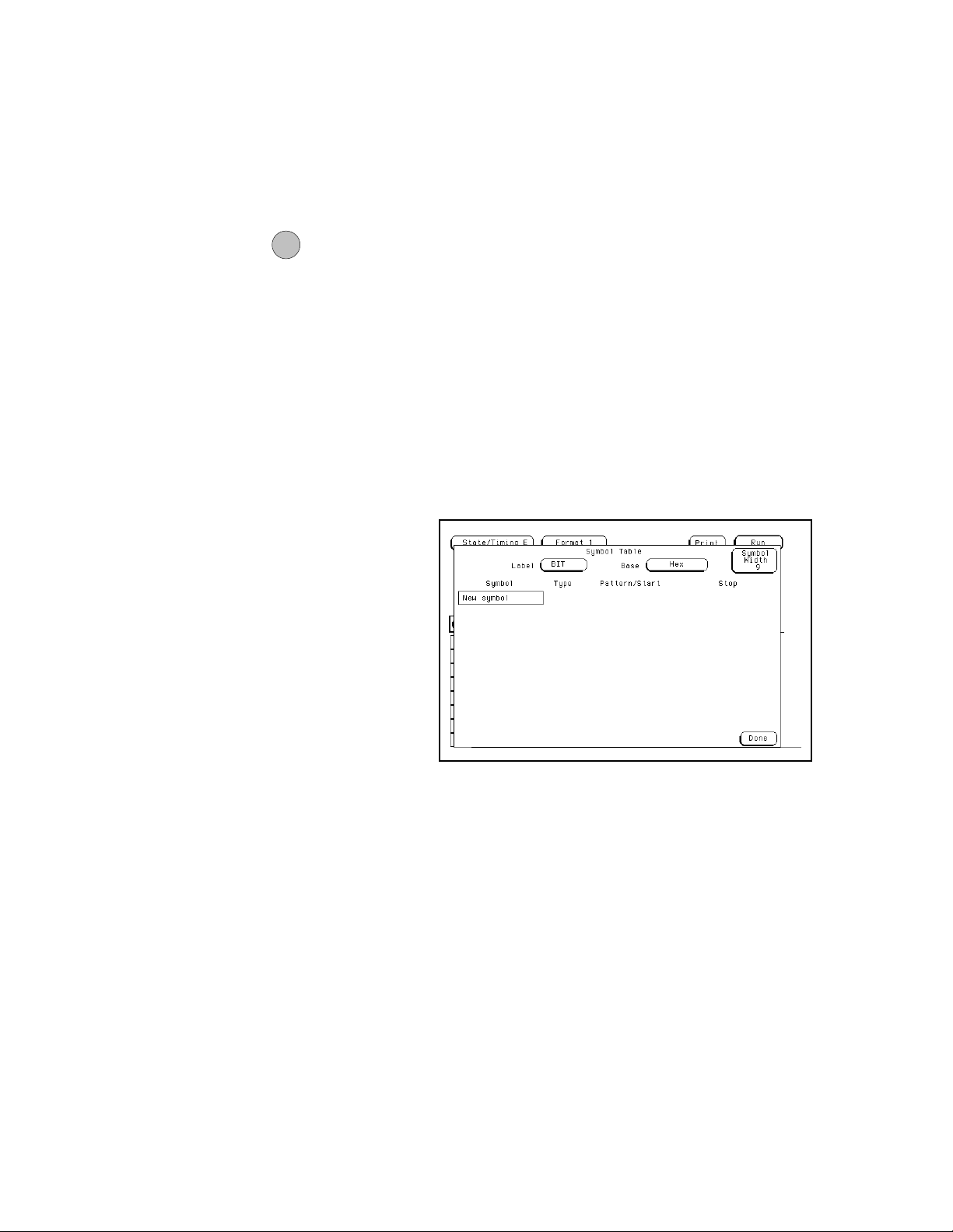
You enter a threshold in the pop-up with the keypad by touching the
desired value, units and polarity. When the correct threshold voltage is
displayed, touch DONE. The pop-up will close and the new threshold will
be placed in the pod threshold f ield.
In the state analyzer, the same threshold level applies to a pod’s clock as
to its 16 data bits.
5Specify
Symbols
The logic analyzer supplies Timing and State Symbol Tables in which
youcandefineamnemonicforaspecificbitpatternofalabel.When
measurementsare made by thelogic analyzer, the mnemonic is d isplayed
where the bit pattern occurs if the Symbol base is selected.
It is possible for you to specify up to 200 symbols in the logic analyzer. If
you have only one of the internal analyzers on, all 200 symbols can be
defined in it. If both analyzers are on, the 200 symbols are split between
the two. For example, analyzer 1 may have 150, leaving 50 available for
analyzer 2.
To access the Symbol Table in either the State or Timing Format
Specification menus, touch the Symbols field. You will see a new menu
as shown. This is the default setting for the Symbol Table in both the
timing and state analyzers.
Figure 5-13. Symbol Table Menu
Menus HP 16510B
5-14 Front-Panel Reference
Page 75

There are four fields in theSymbol Table menu. They are:
• Label
• Base
• Symbol Width
• Symbol name
Label. The Label field identifies the label for which you are specifying the
symbols. If you select this field you will get a pop-up that lists all the
labels that are turned on in that analyzer.
Figure 5-14. Label Pop-up Menu
Each label hasa separate symbol table.This allows you to give the same
name to symbols defined under different labels. In the Label pop-up touch
thelabelforwhichyouwishtospecifysymbols.
Base. The Basefield tells you the number base in which the pattern will
be specified. The base you choose here will appear in the Find Pattern
field of the Timing Trace Specification menu in the timing analyzer, or the
pattern field of the State Trace Specification menu in the state analyzer.
These are covered later in this chapter.
HP 16510B Menus
Front-Panel Reference 5-15
Page 76

To change the base, touch the current base .You will see the following
pop-up menu.
Figure 5-15. Base Pop-up
If more than 20 channels are assigned to a label, the Binary option is not
offered in the pop-up. The reason for this is that when a symbol is
specified as a range, there is only enough room for 20 bits to be displayed
on the screen.
When you decide which base you want to work in, choose that option
from the number Base pop-up menu.
If you choose the ASCII option, you can see what ASCII characters the
pattern and ranges defined byyour symbols represent. ASCII characters
represented by the decimal numbers 0 to 127 (hex 00 to 7F) are offered on
your logic analyzer. Specifying patterns and ranges for symbols is
discussed in the next section.
Note You cannot specify a pattern or range when the base is ASCII. First
define the pattern or range in one of the other bases, then switch to ASCII
to see the ASCII characters.
Menus HP 16510B
5-16 Front-Panel Reference
Page 77

Symbol Width. The Symbol Width field lets you specify how many
characters of the symbol name will be displayed when the symbol is
referenced in theTiming and State Trace Specification menus, the Timing
Waveforms menu, or the State Listing menu. Selecting this field gives
you the following pop-up.
Figure 5-16. Symbol Pop-up Menu
You can have the logic analyzer display from 1 to all 16 of the characters
in the symbol name. This is covered more in the sections on the Trace
menus, the Waveforms menu, and the State Listing menu later in this
chapter.
Symbol Name. When you first access the Symbol Table, there are no
symbols specified. The symbol name field reads New Symbol. If you
selectthisfieldanalphanumerickeypadpop-upmenuappears.Usethe
keypad to enter the name of your symbol. A maximum of 16 characters
canbeusedinthenameofasymbol.
When you touch DONE fieldin the keypad pop-up menu, the name of the
symbol appears in the symbol name field, and two more fields appear in
the display to the right of the symbol name.
HP 16510B Menus
Front-Panel Reference 5-17
Page 78

Figure 5-17. Symbol Defined as a Pattern
The first of these fields defines the symbol as either a pattern or a range. If
you touch this field, it will toggle between pattern and range.
When the symbol is defined as a pattern, one field (Pattern/start) appears
to specify what the pattern is. Touching this field displays a pop-up with
which you can specify the pattern. Use the keypad and the X (Don’t Care)
key to enter the pattern.
Figure 5-18. Specify Pattern Pop-up
Menus HP 16510B
5-18 Front-Panel Reference
Page 79

If the symbol is defined as a range,two fields appear in which you specify
the upper and lower boundaries of the range. The fields are Pattern/Start
and Stop.
Figure 5-19. Symbol Defined as a Range
Touching either of these fieldsgives you a pop-up with which you can
specify the boundary of the range.
Figure 5-20. Specify Range Pop-up
HP 16510B Menus
Front-Panel Reference 5-19
Page 80

You can specifyranges that overlap or are nested within each other. They
must be specific. Don’t cares are not allowed.
The logic analyzer gives patterns priority over ranges when displaying
measurements. This will be covere d in more detail in the sections "Timing
Waveforms Menus" and "State Listing Menus" later in this chapter. To
add more symbols to your symbol table, touch the field of thelast symbol
defined. A pop-up menu appears as shown.
Figure 5-21. Symbol Pop-up Menu
The first option in the pop-up is Add a Symbol.Itallowsyoutoadd
another symbol. When you select it, you will see an alphanumeric pop-up
menu. Use the keypad to enter the name of your new symbol. When you
select Done, your new symbol will appear in the Symbol Table.
The second option in the pop-up is Modify symbol. If you select this
option, you will see an alphanumeric pop-up menu with which you can
change the name of the symbol.
The third option in the pop-up is Delete Symbol. If you select this option,
the symbol will be deleted from the Symbol Table.
Leaving the Symbol Table Menu. When you have specified all your
symbols, you can leave the Symbol Table menu by touching Done.This
puts you back in the Format Specification menu that you were in before
entering the Symbol Table.
Menus HP 16510B
5-20 Front-Panel Reference
Page 81

6ClockThe Clock field is present in the Format Specification menu only in the
state analyzer. This field displays the clocks that are to be used to clock
the logic analyzer. The displaywill be referred to as the "clocking
arrangement."
The HP 16510B Logic Analyzer has five clock channels, each of which is
on a pod.The clocks are connected through the podssimplyfor
convenience. The clock channels are labeled J, K, L, M, and N and are on
pods 1 through 5, respectively. The clocking of the state analyzer is
synchronous with your system because the analyzer uses the clocks
present in your system that assure valid data.
When you select the Clock field, you will see the following pop-up menu
with which you specify the clock.
Figure 5-22. Clock Pop-up Menu
You can use one of the clocks alone or combine them to build one
clocking arrangement.
If you select a field to the right of one of the clocks in the pop-up, you will
see another pop-up menu:
HP 16510B Menus
Front-Panel Reference 5-21
Page 82

Figure 5-23. Single Clock Pop-up Menu
With this menu you set the condition needed by each clock. You can
specify that the logic analyzer looks for the negative edge of the clock, the
positive edge, either edge, ahigh level, or a low level, or you can turn the
clock off.
The clocks arecombined by ORing and ANDing them. Clock edges are
ORed to clock edges, clock levels are ORed to clock levels, and clock
edges are ANDed to clock levels.
Forexample,ifyouselect↓ for the J clock, ↑ for the K clock, High for
the M clock, and Low for the N clock, the resulting clocking arrangement
will appear in the displa yas:
Figure 5-24. Example of a Clocking Arrangement
Menus HP 16510B
5-22 Front-Panel Reference
Page 83

With this arrangement, the logic analyzer will clock the data when there is
a negative edge of the J clock OR a positive edge of the K clock, AND
when there is a high level on the M clock OR a low level on the N c lock.
You must always specify at least oneclockedge. If you try to use only
clock levels, the logic analyzer will display a message telling you that at
least one edge is required.
7 Pod Clock Your logic analyzer has the capability of clocking data in three different
ways. The pod Clock fields in the State Format Specification menu
allow you to specify which of the three ways you want to clock the data.
Each pod assigned to the state analyzer has a pod Clock field associated
with it. As with the Clock field discussed in the previous section, the pod
Clock fields are present only in the state analyzer. Selecting one of the
pod Clock fields gives you the following pop-up menu:
Figure 5-25. Pod Clock Field Pop-up Menu
HP 16510B Menus
Front-Panel Reference 5-23
Page 84

Normal. This option specifies that clocking will be done in single phase.
That is, the clocking arrangement located in the Clock field above the
pods in the State Format Specification menu will be used to clock all data
(pods) assigned to this machine.
For example, suppose that the Clock field looks like the following:
Figure 5-26. Single Phase Clocking Arrangement
In Normal mode the state analyzer will sample data present on all pods
assigned to this machine on a negative edge of the J clock OR on a
positive edge of the K clock.
Demultiplex. With the HP 16510B Logic Analyzer, you can clock two
different types of data that occur on the same lines. For instance, lines that
transfer both address and data information need to be clocked at different
times in order to getthe right information at the right time. The
Demultiplex option provides the means to do this.
When you select the Demultiplex option, the pod Clock field changes to
Master | Slave, and two clock fields appear above the pods where just one
Clock field used to be. These fields arethe Master Clock and Slave
Clock,asshown:
Menus HP 16510B
5-24 Front-Panel Reference
Page 85

Figure 5-27. Master Clock and Slave Clock
Demultiplexing is done on the data lines of the specified pod to read only
the lower eight bits. This is two phase clocking, with the Master Clock
following the Slave Clock. The analyzer first looks for the clocking
arrangement that you specify in theSlave Clock. When it sees that, the
analyzer clocks the data present on bits 0-7 of the pod, then waits for the
clocking arrangement that you specify in the Master Clock.Whenitsees
that clocking arrangement, it again clocks the data present on bits 0-7 of
the pod. The upper eight bits of the pod are ignored and don’t need to be
connected to your system.
Notice that the bit numbers that appear above the bit assignment field have
changed. The bits are now numbered 7....07....0 instead of 15....87....0.
This helps you set up the analyzer to clock the right information at the
right time.
The address/data lines AD0-AD7 on the 8085 microprocessor are an
example for Demultiplex. During part of the operating time the lines have
an address on them, and during other times they have data on them.
Connect the lower eight bits of one of the pods to these eight lines and set
the Slave and Master Clocks for the pod such that they clock the data and
the address at the proper time.
In this example, you may choose to assign the bits in the State Format
Specification menu similar to that shown in the following figure. In this
case you would want to clock the address with the Slave Clock and the
data with the Master Clock.
HP 16510B Menus
Front-Panel Reference 5-25
Page 86

Figure 5-28. Bit Assignments for Master and Slave
The Master and Slave Clocks can have the same c locking arrangements.
The clocking is still done the same way, with the lower eight bits being
clocked first on the Slave Clock, then on the Master Clock.
Mixed Clocks.TheMixed Clocks option allows you to clock the lower
eight bits of a pod separately from the upper eight bits. The state analyzer
uses Master and Slave Clocks to do this. If you select this option in the
pod Clock pop-up, the pod Clock field changes to Master | Slave,andtwo
Clock fields, Master and Slave, appear above the pods.
As in Demultiplex, the Maste rClock follows the Slave Clock. The state
analyzer looks for the clocking arrangement given by Slave Clock and
clocks the lower eight bits. Then it looks for the clock arrangement given
by the Master Clock and clocks the upper eight bits. Unlike Demultiplex,
all 16 bits of a pod are sampled.
The Master and Slave Clocks can have the same c locking arrangements.
The clocking is still done the same way, with the lower eight bits clocked
on the Slave Clock and the upper eight bits clocked on the Master Clock.
Menus HP 16510B
5-26 Front-Panel Reference
Page 87

8ClockPeriod This field provides greater measurement accuracy when your state input
clock period isgreater than 60 ns. When you select >60ns,thestate
analyzer provides greater immunity against noise or ringing in the state
input clock signal; therefore, the logic analyzer provides greater accuracy
when triggering another state or timing analyzer or the BNC trigger out.
If your State input clock period is less than 6 0 ns, you should select <60
ns. This disables the Count field in the State Trace Specification menu
because the maximum clock rate when counting is 16.67 MHz (60 ns
clock period).
Timing Trace
Specification
Menu
The Timing Trace Specification menu lets you specify the trigger point for
the logic analyzer to start capturing data and the manner in which the
analyzer will capture data. You configure the timing analyzer to find a
pattern first and then a transition in the signal or signals.
The menu looks like that shown below. This is the default setting for the
menu.
2
4
5
6
7
8
Figure 5-29. Timing Trace Specification Menu
1
3
HP 16510B Menus
Front-Panel Reference 5-27
Page 88

Timing Trace
Specification
Menu Fields
The fields in the Timing Trace Specification menu are:
1) Run/Trace Mode
2) Armed b y
3) Acquisition mode
4) Label
5) Base
6) Find Pattern
7) Pattern Duration (present for ______)
8) Then find Edge
These are described in the following sections.
1 Run/Trace
Mode
You specify the mode in which the timing analyzer will trace data when
you touch Run. You have two choices for tracemode: Single and
Repetitive. When you touch Run and hold your finger on the field, you
will see the following pop-up menu:
Figure 5-30. Run Field Pop-up Menu
You select the trace mode by touching the Run field, and, without lifting
your finger from the screen, move it to the desired trace mode. When you
lift your finger, the logic analyzer traces data in the mode you specify. If
you wish to abort the trace after you touch Run but before the trace starts,
move your finger to Cancel before lifting your finger.
Menus HP 16510B
5-28 Front-Panel Reference
Page 89

Single Trace mode acquires data once per trace. Repetitive Trace mode
repeats single acquisitions until Stop is touched, or until the time interval
between two specified patterns is lessthan or greater than a specified
value, or within or not within a specified range. The StopMeasurement
feature is explained in detail in "Markers Pattern" in both the "Timing
Waveforms" and "State Listing" sections of Chapter 6 of this manual.
2ArmedByThe Armed By field is present when more than one analyzer ison at the
same time. The Armed by field lets you specify how your timing analyzer
is to be armed. The analyzer can be armed by Run, the other analyzer, or
an external arm from the IMB (Intermodule Bus). "Intermodule
Measurements" are covered in chapter 10 of the HP 16500A Reference
Manual.
When you select the Armed by field, a pop-up menu appears like that
shown below. Use this menu to select the arming option for your analyzer.
Figure 5-31. Armed By Pop-up Menu
HP 16510B Menus
Front-Panel Reference 5-29
Page 90

3 Acquisition
Mode
The Acquisition mode field allows you to specify the mode in which you
want the timing analyzer to acquire data. You are given two choices for
the mode of acquisition: Transitional and Glitch. When you touch this
field, the field toggles from one mode to the other.
Transitional Acquisition Mode. When the logic analyzer is operating in
the Transitional Acquisition mode, itsamples the data at regular intervals,
but it stores data in memory only when there have been transitions in the
signals since the last data sample was stored. A time tag that is stored with
each sample allows reconstruction of the samples in the Timing
Waveforms display.
Transitional timing always samples at a rate of 100 MHz (10 ns/sample).
This provides maximum timing resolution even in records that span long
time windows. Time covered by a full memory acquisition varies with the
number of pattern changes in the data. If there are many transitions, the
data may end prior to the end of the time window desired because the
memory is full. However, a prestore qualification in your logic analyzer
insures that data will be captured and displayed between the left side of
the screen and the trigger point.
The figure below illustrates Transitional acquisition, comparing it to
Traditional acquisition.
Figure 5-32. Transitional Timing vs. Traditional Timing
Menus HP 16510B
5-30 Front-Panel Reference
Page 91

Traditional timing samples and stores data at regular intervals.
Transitional timing samples data at regular intervals but stores a sample
only when there has been a transition on one or more of the channels. This
makes it possible for Transitional timing to store more information in the
same amount of memory.
Glitch Acquisition Mode. A glitch is defined as any transition that
crosses the logic threshold more than once between samples. It can be
caused by capacitive coupling between traces, power supply ripple, or a
number of other events. The glitch, in turn, can cause major problems in
your system.
Your logic analyzer has the capability of triggering on a glitch and
capturing all the data that occurred before it. The glitch must have a width
of at least 5 ns at threshold in order for the analyzer to detect it.
If you want your timing analyzer to trigger on a glitch in the data, set
the Acquisition mode to Glitch. This causes several changes in the
analyzer. One change is thata field for glitch detection in each label is
added to theTiming Trace Specification menu, as shown:
Figure 5-33. Glitch Specification Field
HP 16510B Menus
Front-Panel Reference 5-31
Page 92

With these glitch detection fields you specify on which channel or
channels you want the analyzer to look for a glitch. These fields are
discussedinmoredetailinthe"ThenFindEdge"sectionlaterinthis
chapter.
Glitch Acquisition mode causes the storage memory to be cut in half, from
1k to 512. Half of the memory (512) is allocated for storing the data
sample, and the other half for storing the second transition of a glitch in a
sample. Every sample is stored. The sample rate varies from 20 Hz to 50
MHz (50 ms/sample to 20 ns/sample) and is automatically selecte d by the
timing analyzer to insure complete data in the window of interest.
When your timing analyzer triggers on a glitch and displays the data, the
glitch appears in the waveform display as shown below.
4LabelThe Label fields contain the labels that you define in the Timing
Figure 5-34. Glitch in Timing Waveform
Format Specification menu. If there are more labels than can fit on screen,
use the KNOB to view those that aren’t displayed.
Menus HP 16510B
5-32 Front-Panel Reference
Page 93

5BaseThe Base fields allow you to specify the number base in which you want
to define a pattern for a label. The Base fields also let you use a symbol
that was specified in the Timing Symbol Table for the pattern. Each label
has its own base defined separately from the other labels. If you select one
of the Base fields, you will see the following pop-up menu. Decide which
base you want to define your pattern in and select that option.
One of the options in the Basepop-up is ASCII. It allows you to see the
Figure 5-35. Base Pop-up Menu
ASCII characters that are represented by the pattern you specified in the
Find Pattern field.
In the figure above, the Find Pattern fieldisnolongeraselectablefield
Figure 5-36. ASCII Defined as Numeric Base
whenthebaseisASCII. If you touch this field, the message "ASCII entry
not available" appears. You cannot enter ASCII characters directly. You
must specify a pattern in one of the other bases; then switch the base to
ASCII and to see what characters the pattern represents.
HP 16510B Menus
Front-Panel Reference 5-33
Page 94

The Symbol optionintheBase pop-up allows you to use a symbol that
has been specified in the Timing Symbol Tables as a pattern, or specify
absolute and enter another pattern. You specify the symbol you want to
use in the Find Pattern field.
6 Find Pattern With the Find Pattern fields, you configure your timing analyzer to look
for a certain pattern in the data. Each label has its own pattern field that
you use to specify a pattern for that label.
During a run, the logic analyzer looks for apatternin your data generated
by the logical AND of all the labels’ patterns. That is, it looks for a
simultaneous occurrence of the specifie d patterns. When it finds the
pattern, it triggers at the point that you specified in the Then find Edge
fields. See the "Then Find Edge" section later in this chapter for more
information about edge triggering.
You specify a pattern by touching the Find Pattern field. A keypad
pop-up appears with which you enter the desired pattern. The pop-up will
vary depending on the base you choose and the number of c hannels you
assign to that label.
Figure 5-37. Specify Pattern Pop-up for Find
Enter your pattern in the pop-up and touch DONE. The pattern appears
under the label in the Find Pattern field.
Menus HP 16510B
5-34 Front-Panel Reference
Page 95

As mentioned in the previous section on the Base field, if you specify
ASCII as the base for the label, you won’t be able to enter a pattern. You
must specify one of the other number bases to enter the pattern, then you
can switch the base to ASCII and see what ASCII characters the pattern
represents.
If you choose Symbols in the Base field, you can use one of the symbols
specified in the Timing Symbol Tables as the pattern. The Find Pattern
field looks similar to that below:
Figure 5-38. Symbol Defined in Base Field
HP 16510B Menus
Front-Panel Reference 5-35
Page 96

If you select this field you get a pop-up similar to that shown:
Figure 5-39. Symbol Selection Pop-up for Find
The pop-up lists all the symbols defined for that label. It also contains an
option absolute. Placing the blue bar on this option causes another field
within the pop-up to appear. This field is labeled offset______.Theoffset
field lets you specify a pattern not given by one of your symbols.
To select anoption from the pop-up, use the KNOB to roll the symbols up
and down until the desired symbol is highlighted by the blue bar. Touch
Done to close the pop-up and place the symbol name in theFind Pattern
field under the label.
When you specify symbols in the Timing Symbol Tables,youalso
specify the number of characters in the symbol name that are to be
displayed. If you specify to display only three characters of a symbol
name, only REA of READ andWRI of WRITE would be displayed in the
Find Pattern field. In addition, only the first three letters of absolute
would be displayed.
Menus HP 16510B
5-36 Front-Panel Reference
Page 97

7 Pattern
Duration (present
for______)
There are two fields with which you specify the Pattern Duration. They
are located next to present for ______ in the Timing TraceSpecification
menu. You use these fields to tell the timing analyzer to trigger before or
after the specified pattern has occurred for a given length of time.
The first field can be set to > (greaterthan) or < (less than). When you
touch this field, it toggles between > and <. The second field specifies the
duration of the pattern. If you select > in the first field, you can set the
durationtoavaluebetween30nsand10ms.Ifyouselect< in the first
field,youcansetthedurationtoavaluebetween40nsand10ms.Ifyou
attempt to set the duration to a value outside the given range, the analyzer
will automatically set it to the nearest limit.
To change the value of the pattern duration, touch the second field to get a
pop-up keypad similar to theone shown:
With the keypad enter the desired value and units for pattern duration,
Figure 5-40. Patten Duration (present for) Pop-up
then touch DONE. Your value for pattern duration will appear in the fie ld.
HP 16510B Menus
Front-Panel Reference 5-37
Page 98

As an example, suppose you configure the present for field as shown:
Figure 5-41. Example of Pattern > 50 ns
This configuration tells the timing analyzer to look for a certain pattern
specified by you that has a duration of greater than 50 ns. Once the timing
analyzer has found the pattern, it can look for the trigger.
Choosing < (less than) forces glitch and edge triggering off, and the
timing analyzer triggers immediately at the end of the pattern that meets
the duration requirements. The fields with which you specify edges and
glitches don’t appear in the menu. For instance, if you configure the
present for field as shown:
Figure 5-42. Example of Pattern Duration < 100 ns
The analyzer will trigger when the specified pattern has a duration less
than 100 ns. The pattern must also be validfor at least 20 ns.
Menus HP 16510B
5-38 Front-Panel Reference
Page 99

8 Then Find Edge With the Then find Edge fields you can specify the edges (transitions) of
your data on which your timing analyzer triggers. You can specify a
positive edge, a negative edge, or either edge. Each label has its own edge
trigger specification field so that you can specify an edge on any channel.
When you specify an edge on more than one channel, the timing analyzer
logically ORs them together to look for the trigger point. That is, it
triggers when it sees any one of the edges you specified. It alsoANDs the
edges with the pattern you specified in the Find Pattern fields. The logic
analyzer triggers on an edge following the valid duration of the pattern
while the pattern is stillpresent.
Tospecifyanedge,touchoneoftheThen find Edge fields. You will see
a pop-up similar to that shown below.
Figure 5-43. Specify Edge Pop-up for Then Find
The top row of periods and arrows inyour pop-up may look different than
this depending on the number of channels you assigned to the label. Each
period in the pop-up indicatesthat no edge is specified for that channel.
To specify a negative edge, place the cursor on one of the periods in the
pop-up and touch the ↓. The period changes to ↓. To specify a positive
edge, touch the ↑. The period changes to ↑.
If you want the analyzer to trigger on either a positive or a negative edge,
touch the . The period changes to .
HP 16510B Menus
Front-Panel Reference 5-39
Page 100

If you want to delete an edge specification, place the cursor on the arrow
for that channel and touch the . (period). To clear an entire label, touch
CLEAR in the pop-up.
When you have finished specifying edges, touch Done to close the pop-up.
An example of a positive, negative, and either edge specification is shown
below.
Figure 5-44. Combination of Edges Specified
Note When you close the pop-up after specifying edges, you will see ($$..)in
the Then find Edge field. These indicate edges have been specified;
however, the logic analyzer can’tdisplay them correctly unless you have
selected Binary for the base.
Menus HP 16510B
5-40 Front-Panel Reference
 Loading...