

HP 15-db0xxx, 15-db1xxx, 15g-db0xxx, 15g-db1xxx, 15q-dy0xxx Maintenance And Service Manual
...Page 1

Maintenance and Service Guide
HP 15 Laptop PC
Page 2

© Copyright 2018, 2019 HP Development
Company, L.P.
AMD, Athlon, Ryzen, and Radeon are
trademarks of Advanced Micro Devices, Inc.
Bluetooth is a trademark owned by its
proprietor and used by HP Inc. under license.
Windows is a trademark of the Microsoft group
of companies.
The information contained herein is subject to
change without notice. The only warranties for
HP products and services are set forth in the
express warranty statements accompanying
such products and services. Nothing herein
should be construed as constituting an
additional warranty. HP shall not be liable for
technical or editorial errors or omissions
contained herein.
Second Edition: February 2019
First Edition: April 2018
Document Part Number: L19675-002
Product notice
This user guide describes features that are
common to most models. Some features may
not be available on your computer.
Not all features are available in all editions of
Windows. This computer may require upgraded
and/or separately purchased hardware, drivers
and/or software to take full advantage of
Windows functionality. Go to
http://www.microsoft.com for details.
Software terms
By installing, copying, downloading, or
otherwise using any software product
preinstalled on this computer, you agree to be
bound by the terms of the HP End User License
Agreement (EULA). If you do not accept these
license terms, your sole remedy is to return the
entire unused product (hardware and software)
within 14 days for a full refund subject to the
refund policy of your seller.
For any further information or to request a full
refund of the price of the computer, please
contact your seller.
Page 3

Important Notice about Customer Self-Repair Parts
CAUTION: Your computer includes Customer Self-Repair parts and parts that should only be accessed by an
authorized service provider. See Chapter 5, "Removal and replacement procedures for Customer Self-Repair
parts," for details. Accessing parts described in Chapter 6, "Removal and replacement procedures for
Authorized Service Provider only parts," can damage the computer or void your warranty.
iii
Page 4

iv Important Notice about Customer Self-Repair Parts
Page 5

Safety warning notice
WARNING! To reduce the possibility of heat-related injuries or of overheating the device, do not place the
device directly on your lap or obstruct the device air vents. Use the device only on a hard, at surface. Do not
allow another hard surface, such as an adjoining optional printer, or a soft surface, such as pillows or rugs or
clothing, to block airow. Also, do not allow the AC adapter to contact the skin or a soft surface, such as
pillows or rugs or clothing, during operation. The device and the AC adapter comply with the user-accessible
surface temperature limits dened by the International Standard for Safety of Information Technology
Equipment (IEC 60950-1).
v
Page 6

vi Safety warning notice
Page 7

Table of contents
1 Product description ....................................................................................................................................... 1
2 Getting to know your computer ...................................................................................................................... 6
Right side ............................................................................................................................................................... 6
Left side ................................................................................................................................................................. 7
Display .................................................................................................................................................................... 8
Keyboard area ........................................................................................................................................................ 9
TouchPad ............................................................................................................................................. 9
Lights ................................................................................................................................................. 10
Button, speakers, and vent ............................................................................................................... 11
Special keys ....................................................................................................................................... 12
Action keys ........................................................................................................................................ 13
Bottom ................................................................................................................................................................. 14
Labels ................................................................................................................................................................... 15
3 Illustrated parts catalog .............................................................................................................................. 16
Computer major components .............................................................................................................................. 16
Cables ................................................................................................................................................................... 21
Display assembly subcomponents ...................................................................................................................... 22
Miscellaneous parts ............................................................................................................................................. 24
Mass storage devices ........................................................................................................................................... 26
4 Removal and replacement procedures preliminary requirements .................................................................... 28
Tools required ...................................................................................................................................................... 28
Service considerations ......................................................................................................................................... 28
Plastic parts ....................................................................................................................................... 28
Cables and connectors ...................................................................................................................... 28
Drive handling ................................................................................................................................... 29
Workstation guidelines ..................................................................................................................... 29
Electrostatic discharge information .................................................................................................................... 29
Generating static electricity .............................................................................................................. 30
Preventing electrostatic damage to equipment ............................................................................... 30
Personal grounding methods and equipment .................................................................................. 31
Grounding the work area ................................................................................................................... 31
Recommended materials and equipment ........................................................................................ 31
Packaging and transporting guidelines .............................................................................................................. 32
vii
Page 8

5 Removal and replacement procedures for Customer Self-Repair parts ............................................................. 33
Component replacement procedures .................................................................................................................. 33
Preparation for disassembly ............................................................................................................. 33
Optical drive ....................................................................................................................................... 34
6 Removal and replacement procedures for authorized service provider parts .................................................... 37
Component replacement procedures .................................................................................................................. 37
Bottom cover ..................................................................................................................................... 38
Battery ............................................................................................................................................... 41
Memory module ................................................................................................................................ 43
Hard drive .......................................................................................................................................... 45
Solid-state drive ................................................................................................................................ 47
Solid-state drive bracket and connector board ................................................................................ 48
WLAN module .................................................................................................................................... 50
Hard drive connector board ............................................................................................................... 51
USB/card reader board ...................................................................................................................... 52
TouchPad button board ..................................................................................................................... 53
TouchPad module .............................................................................................................................. 54
Fan ..................................................................................................................................................... 56
Heat sink assembly ........................................................................................................................... 57
Display assembly ............................................................................................................................... 61
System board .................................................................................................................................... 71
Speakers ............................................................................................................................................ 74
Power connector cable (DC-in) .......................................................................................................... 75
Top cover with keyboard ................................................................................................................... 76
7 Using Setup Utility (BIOS) ............................................................................................................................. 77
Starting Setup Utility (BIOS) ................................................................................................................................ 77
Updating Setup Utility (BIOS) .............................................................................................................................. 77
Determining the BIOS version ........................................................................................................... 77
Downloading a BIOS update .............................................................................................................. 78
8 Using HP PC Hardware Diagnostics ................................................................................................................ 79
Using HP PC Hardware Diagnostics Windows (select products only) ................................................................. 79
Downloading HP PC Hardware Diagnostics Windows ....................................................................... 79
Downloading the latest HP PC Hardware Diagnostics Windows version ....................... 80
Downloading HP Hardware Diagnostics Windows by product name or number
(select products only) ..................................................................................................... 80
Installing HP PC Hardware Diagnostics Windows ............................................................................. 80
Using HP PC Hardware Diagnostics UEFI ............................................................................................................. 80
viii
Page 9

Starting HP PC Hardware Diagnostics UEFI ....................................................................................... 81
Downloading HP PC Hardware Diagnostics UEFI to a USB ash drive .............................................. 81
Downloading the latest HP PC Hardware Diagnostics UEFI version .............................. 81
Downloading HP PC Hardware Diagnostics UEFI by product name or number
(select products only) ..................................................................................................... 81
Using Remote HP PC Hardware Diagnostics UEFI settings (select products only) ............................................. 82
Downloading Remote HP PC Hardware Diagnostics UEFI ................................................................. 82
Downloading the latest Remote HP PC Hardware Diagnostics UEFI version ................. 82
Downloading Remote HP PC Hardware Diagnostics UEFI by product name or
number ............................................................................................................................ 82
Customizing Remote HP PC Hardware Diagnostics UEFI settings .................................................... 82
9 Backing up, restoring, and recovering ........................................................................................................... 84
Backing up information and creating recovery media ........................................................................................ 84
Using Windows tools ......................................................................................................................... 84
Using the HP Cloud Recovery Download Tool to create recovery media (select products only) ..... 84
Restoring and recovery ........................................................................................................................................ 85
Restoring, resetting, and refreshing using Windows tools .............................................................. 85
Recovering using HP Recovery media ............................................................................................... 85
Changing the computer boot order ................................................................................................... 85
10 Specications ............................................................................................................................................ 86
Computer specications ...................................................................................................................................... 86
39.6-cm (15.6-in) display specications ............................................................................................................. 87
M.2 SATA solid-state drive specications ............................................................................................................ 87
M.2 PCIe solid-state drive specications ............................................................................................................ 88
Hard drive specications ..................................................................................................................................... 89
11 Power cord set requirements ...................................................................................................................... 90
Requirements for all countries ............................................................................................................................ 90
Requirements for specic countries and regions ................................................................................................ 90
12 Recycling .................................................................................................................................................. 92
Index ............................................................................................................................................................. 93
ix
Page 10

x
Page 11

1 Product description
Table 1-1 Product components and their descriptions
Category Description
Product Name HP 15 Laptop PC
Model numbers:
15-db0xxx, 15-db1xxx, 15g-db0xxx, 15g-db1xxx, 15q-dy0xxx, 15q-dy1xxx, 15z-db000, 15z-db100
Processor AMD processors:
A9-9425 (3.1 GHz, turbo up to 3.7 GHz), 2133 MHz/1 MB L2 cache, dual core, 15 W
A6-9225 (2.6 GHz, turbo up to 3.0 GHz), 2133 MHz/1 MB L2 cache, dual core, 15 W
A4-9125 (2.3 GHz, turbo up to 2.6 GHz), 2133 MHz/1 MB L2 cache, dual core, 15 W
E2-9000e (1.5 GHz, turbo up to 2.0 GHz), 1866 MHz/1 MB L2 cache, dual core, 6 W
Athlon® 300U (2.4 GHz, turbo up to 3.3 GHz), 2400 MHz/3 MB L3 cache, dual core
Ryzen™ 7-3700U (2.3 GHz, turbo up to 4.0 GHz), 6 MB L2 + L3 cache, 2400 MHz, quad core, 15 W
Ryzen 5-3500U (2.1 GHz, turbo up to 3.7 GHz), 6 MB L2 + L3 cache, 2400 MHz, quad core, 15 W
Ryzen 3-3200U (2.6 GHz, turbo up to 3.5 GHz), 5 MB L2 + L3 cache, 2400 MHz, dual core, 15 W
Ryzen 5-2500U (2.0 GHz, turbo up to 3.6 GHz), 6 MB L2 + L3 cache, 2400 MHz, quad core, 15 W
Ryzen 3-2300U (2.0 GHz, turbo up to 3.4 GHz), 6 MB L2 + L3 cache, 2400 MHz, quad core, 15 W
Ryzen 3-2200U (2.5 GHz, turbo up to 3.4 GHz), 1 MB L2 cache, 2400 MHz, dual core, 15 W
Graphics Supports HD decode, DX12, HDMI
Internal graphics:
AMD Radeon™ RX Vega 10 Mobile Graphics (Ryzen 7 processor)
AMD Radeon Vega 8 Mobile Graphics (Ryzen 5 processor)
AMD Radeon Vega 6 Mobile Graphics (Ryzen 3-2300 processor)
AMD Radeon Vega 3 Mobile Graphics (Ryzen 3-2200, Athlon 300U processor)
AMD Radeon R5 Graphics (A9 processor)
AMD Radeon R4 Graphics (A6 processor)
AMD Radeon R3 Graphics (A4 processor)
AMD Radeon R2 Graphics (E2 processor)
External graphics:
AMD Radeon 535 with up to 2 GB of dedicated video memory
AMD Radeon 530 with up to 4 GB of dedicated video memory
AMD Radeon 530 with up to 2 GB of dedicated video memory
1
Page 12

Table 1-1 Product components and their descriptions (continued)
Category Description
AMD Radeon 520 with up to 2 GB of dedicated video memory
Panel 39.6 cm (15.6 in), WLED, eDP, slim-at (3.2 mm), 16:10 ultra wide aspect ratio:
High denition (HD) (1366 × 768), BrightView, SVA, 220 nits
HD (1366 × 768), anti glare, SVA, 220 nits
HD (1366 × 768), BrightView, SVA, 200 nits, Touch on Panel (TOP)
Full high-denition (FHD) (1920 × 1080), anti glare, SVA, 220 nits
FHD (1920 × 1080), anti glare, UWVA, 220 nits, narrow bezel
Touch solution with bezel, multi-touch enabled
Memory Two memory module slots (Ryzen, A9 processors):
Memory is non-customer accessible/non-upgradeable
DDR4-2400 dual channel support (Ryzen, Athlon processors)
DDR4-1866 dual channel support (A9 processors)
Supports up to 16 GB of system RAM in the following congurations:
● 16384 MB (8192 MB × 2)
● 12288 MB (8192 MB × 1 + 4096 MB × 1)
● 8192 MB (8192 MB × 1 + 4096 × 2)
● 4096 MB (4096 MB × 1)
One memory module slot (E2/A4/A6 processors):
Memory is non-customer accessible/non-upgradeable
DDR4-1866 single channel support
Supports up to 8 GB of system RAM in the following congurations:
● 8192 MB (8192 MB × 1)
● 4096 MB (4096 MB × 1)
Primary storage Single hard drive congurations, 6.35 cm (2.5 in), 7.0 mm/7.2 mm/9.5 mm, SATA hard drives:
2 TB, 5400 rpm, 9.5 mm (7.2 mm bridge to 9.5 mm)
1 TB, 5400 rpm, 9.5 mm (7.2 mm bridge to 9.5 mm)
500 GB, 5400 rpm, 7.0 mm
M.2, SATA-3, solid-state drives:
256 GB, TLC
128 GB, TLC
PCIe, NVMe, M.2 solid-state drives:
256 GB
Dual storage congurations (Ryzen, Athlon, and A9 processors):
2 Chapter 1 Product description
Page 13

Table 1-1 Product components and their descriptions (continued)
Category Description
256 GB, PCIe, solid-state drive + 1 TB, 5400 rpm hard drive
256 GB, SATA-3, TLC, solid-state drive + 1 TB, 5400 rpm hard drive
128 GB, SATA-3, TLC, solid-state drive + 1 TB, 5400 rpm hard drive
Optical drive 9.0 mm tray load
DVD+/-RW Double-Layer Writer
Camera HP TrueVision HD Camera - indicator LED, USB2.0, HD BSI sensor, f2.0
720p by 30 frames per second
Single digital microphone
HP Webcam - VGA camera, indicator LED, USB 2.0, f2.4
640 × 480 by 30 frames per second
Single digital microphone
Audio Audio Application Name: HP Audio Control
Dual speakers
Ethernet Ethernet Integrated 10/100/1000 NIC
Wireless networking Compatible with Miracast-certied devices
Integrated Wireless options with dual antennas (M.2/PCIe):
Realtek RTL8822BE 802.11ac 2 × 2 Wi-Fi + Bluetooth® 4.2 Combo Adapter (MU-MIMO supported)
Integrated Wireless options with single antenna (M.2/PCIe):
Realtek RTL8821CE 802.11ac 1 × 1 Wi-Fi + Bluetooth 4.2 Combo Adapter (MU-MIMO supported)
Realtek RTL8723DE 802.11bgn 1 × 1 Wi-Fi + Bluetooth 4.2 Combo Adapter
External media cards HP Multi-Format Digital Media Card Reader
Supports SD/SDHC/SDXC
Push-pull insertion/removal
Internal card
expansion
Ports Hot plug/unplug and auto detect for correct output to wide-aspect vs. standard aspect video (auto adjust
One M.2 slot for solid-state drive
One M.2 slot for WLAN
panel resolution to t embedded panel and external monitor connected)
HDMI v1.4 supporting: up to 1920 × 1080 @ 60Hz
USB 2.0 port (right side)
(2) USB 3.1 Gen 1 ports (left side)
RJ-45/Ethernet
Audio-out (headphone)/audio-in (microphone) combo jack
AC Smart Pin adapter plug
3
Page 14

Table 1-1 Product components and their descriptions (continued)
Category Description
Keyboard/pointing
devices
Power requirements Battery:
Keyboard:
Full-size, textured, island-style keyboard with numeric keypad
Full-size, two coat paint, backlit, island-style keyboard with numeric keypad
Full-size, three coat paint, backlit, island-style keyboard with numeric keypad
TouchPad:
Multitouch gestures enabled
Supports Modern Trackpad Gestures
Taps enabled by default
3-cell Prismatic/Polymer battery, long life, 41 Whr
Supports battery fast charge
AC adapter, barrel type:
65 W Smart, nPFC, right angle, 4.5 mm (models with discrete graphics)
65 W Smart, nPFC, 4.5 mm, EM
65 W Smart, nPFC, 4.5 mm, for use in Argentina (models with discrete graphics)
45 W Smart, nPFC, right angle, 4.5 mm (models with UMA graphics)
45 W Smart, nPFC, 4.5 mm, for use in Argentina (models with UMA graphics)
Power cord (C5):
1 m, conventional
Security Kensington Mini Security Lock
Supports rmware-based Trusted Platform Module (fTPM) 2.0
Operating system FreeDOS 2.0
Windows® 10 Home 64
Windows 10 Home 64 Web/Kiosk
Windows 10 Home 64 Chinese Market CPPP
Windows 10 Home 64 High-End Chinese Market CPPP
Windows 10 Home 64 Plus
Windows 10 Home 64 Plus Web/Kiosk
Windows 10 Home 64 Plus QVC
Windows 10 Home 64 Plus Single Language
Windows 10 Home 64 Plus Single Language Africa Market PPP
Windows 10 Home 64 Plus Single Language APAC EM PPP
4 Chapter 1 Product description
Windows 10 Home 64 Plus Single Language India Market PPP
Page 15

Table 1-1 Product components and their descriptions (continued)
Category Description
Windows 10 Home 64 Plus Single Language Indonesia Market PPP
Windows 10 Home 64 Plus Web/Kiosk
Windows 10 Home 64 QVC
Windows 10 Home 64 Single Language
Windows 10 Home 64 Plus Single Language Africa Market PPP
Windows 10 Home 64 Single Language APAC EM PPP
Windows 10 Home 64 Single Language India Market PPP
Windows 10 Home 64 Single Language Indonesia Market PPP
Windows 10 Home 64 Single Language Value Africa Market PPP
Windows 10 Home 64 Single Language Value APAC EM PPP
Windows 10 Home 64 Single Language Value India Market PPP
Windows 10 Home 64 Single Language Value Indonesia Market PPP
Windows 10 Home 64 Value Notebook Single Language
Windows 10 Home 64 Value Notebook Single Language SEAP
Windows 10 Home 64 Value Notebook Single Language select GEO
Windows 10 Home 64 Web/Kiosk
Windows 10 Home S 64
Windows 10 Home S 64 Web/Kiosk
Windows 10 Home S 64 Plus
Windows 10 Home S 64 Plus Web/Kiosk
Windows 10 Home S 64 Plus QVC
Windows 10 Home S 64 Plus Single Language
Windows 10 Home S 64 QVC
Windows 10 Home S 64 Single Language
Windows 10 Pro 64
Serviceability End user replaceable parts:
AC adapter
Optical drive
5
Page 16
2 Getting to know your computer
Your computer features top-rated components. This chapter provides details about your components, where
they are located, and how they work.
Right side
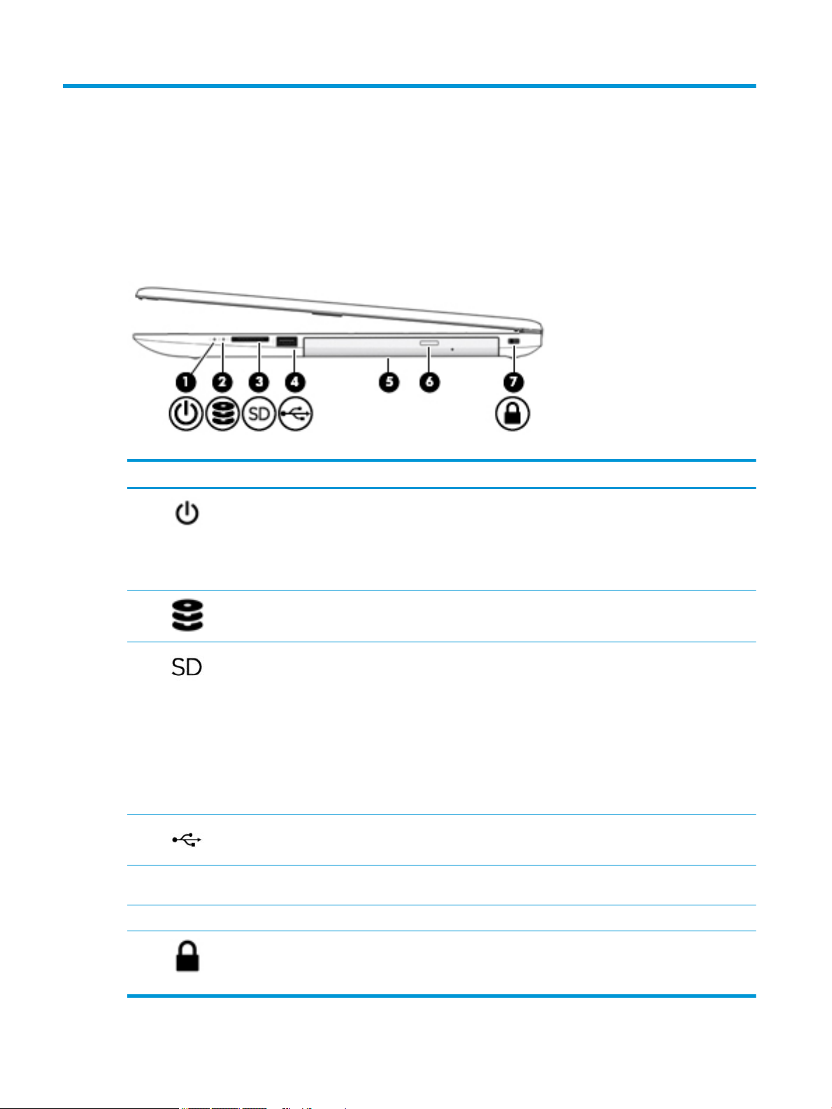
Table 2-1 Right-side components and their descriptions
Component Description
(1) Power light ● On: The computer is on.
● Blinking: The computer is in the Sleep state, a power-saving state. The
computer shuts o power to the display and other unneeded components.
● O: The computer is o or in Hibernation. Hibernation is a power-saving state
that uses the least amount of power.
(2) Drive light ● Blinking white: The hard drive is being accessed.
(3) Memory card reader Reads optional memory cards that enable you to store, manage, share, or access
information.
To insert a card:
1. Hold the card label-side up, with connectors facing the computer.
2. Insert the card into the memory card reader, and then press in on the card
until it is rmly seated.
To remove a card:
▲ Pull to remove the card from the memory card reader.
(4) USB port Connects a USB device, such as a cell phone, camera, activity tracker, or
smartwatch, and provides data transfer.
(5) Optical drive Depending on your computer model, reads an optical disc or reads and writes to an
optical disc.
(6) Optical drive eject button Releases the optical drive disc tray.
(7) Security cable slot Attaches an optional security cable to the computer.
NOTE: The security cable is designed to act as a deterrent, but it may not prevent
the computer from being mishandled or stolen.
6 Chapter 2 Getting to know your computer
Page 17
Left side
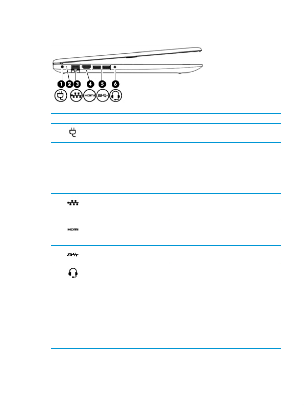
Table 2-2 Left-side components and their descriptions
Component Description
(1) Power connector Connects an AC adapter.
(2) AC adapter and battery light ● White: The AC adapter is connected and the battery is fully
charged.
● Blinking white: The AC adapter is disconnected and the
battery has reached a low battery level.
● Amber: The AC adapter is connected and the battery is
charging.
● O: The battery is not charging.
(3) RJ-45 (network) jack/status lights Connects a network cable.
● White: The network is connected.
● Amber: Activity is occurring on the network.
(4) HDMI port Connects an optional video or audio device, such as a high-
(5) USB SuperSpeed ports (2) Connect a USB device, such as a cell phone, camera, activity
(6) Audio-out (headphone)/Audio-in (microphone)
combo jack
denition television, any compatible digital or audio component,
or a high-speed High-Denition Multimedia Interface (HDMI)
device.
tracker, or smartwatch, and provide high-speed data transfer.
Connects optional powered stereo speakers, headphones,
earbuds, a headset, or a television audio cable. Also connects an
optional headset microphone. This jack does not support
optional standalone microphones.
WARNING! To reduce the risk of personal injury, adjust the
volume before putting on headphones, earbuds, or a headset.
For additional safety information, see the Regulatory, Safety,
and Environmental Notices.
To access this guide:
▲ Select the Start button, select HP Help and Support, and
then select HP Documentation.
NOTE: When a device is connected to the jack, the computer
speakers are disabled.
Left side 7
Page 18
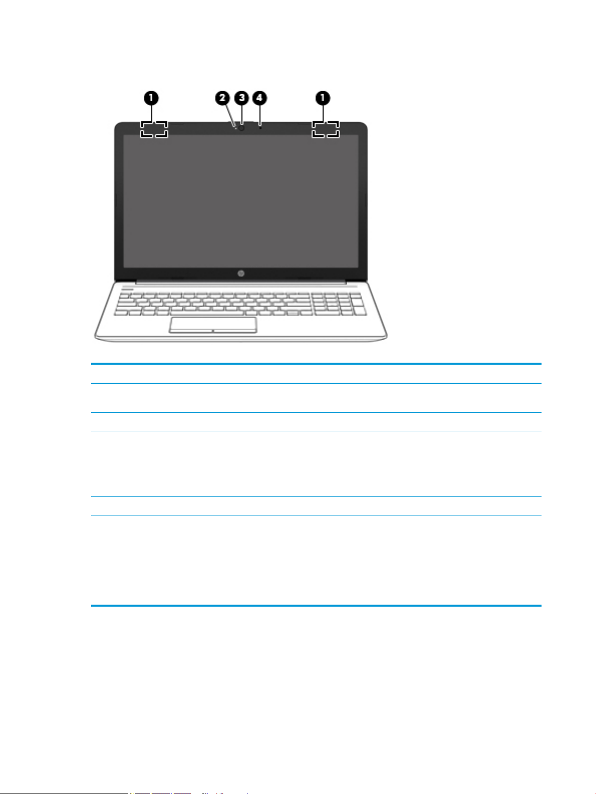
Display
Table 2-3 Display components and their descriptions
Component Description
(1) WLAN antennas* (1 or 2 depending on model) Send and receive wireless signals to communicate with wireless local
area networks (WLANs).
(2) Camera light On: The camera is in use.
(3) Camera Allows you to video chat, record video, and record still images. Some
(4) Internal microphone Records sound.
*The antennas are not visible from the outside of the computer. For optimal transmission, keep the areas immediately around the
antennas free from obstructions.
For wireless regulatory notices, see the section of the Regulatory, Safety, and Environmental Notices that applies to your country or
region.
To access this guide:
▲ Select the Start button, select HP Help and Support, and then select HP Documentation.
cameras also allow a facial recognition logon to Windows, instead of
a password logon..
NOTE: Camera functions vary depending on the camera hardware
and software installed on your product.
8 Chapter 2 Getting to know your computer
Page 19
Keyboard area
TouchPad
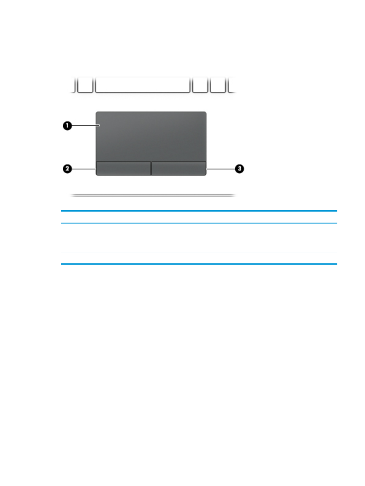
Table 2-4 TouchPad components and their descriptions
Component Description
(1) TouchPad zone Reads your nger gestures to move the pointer or activate items
on the screen.
(2) Left TouchPad button Functions like the left button on an external mouse.
(3) Right TouchPad button Functions like the right button on an external mouse.
Keyboard area 9
Page 20
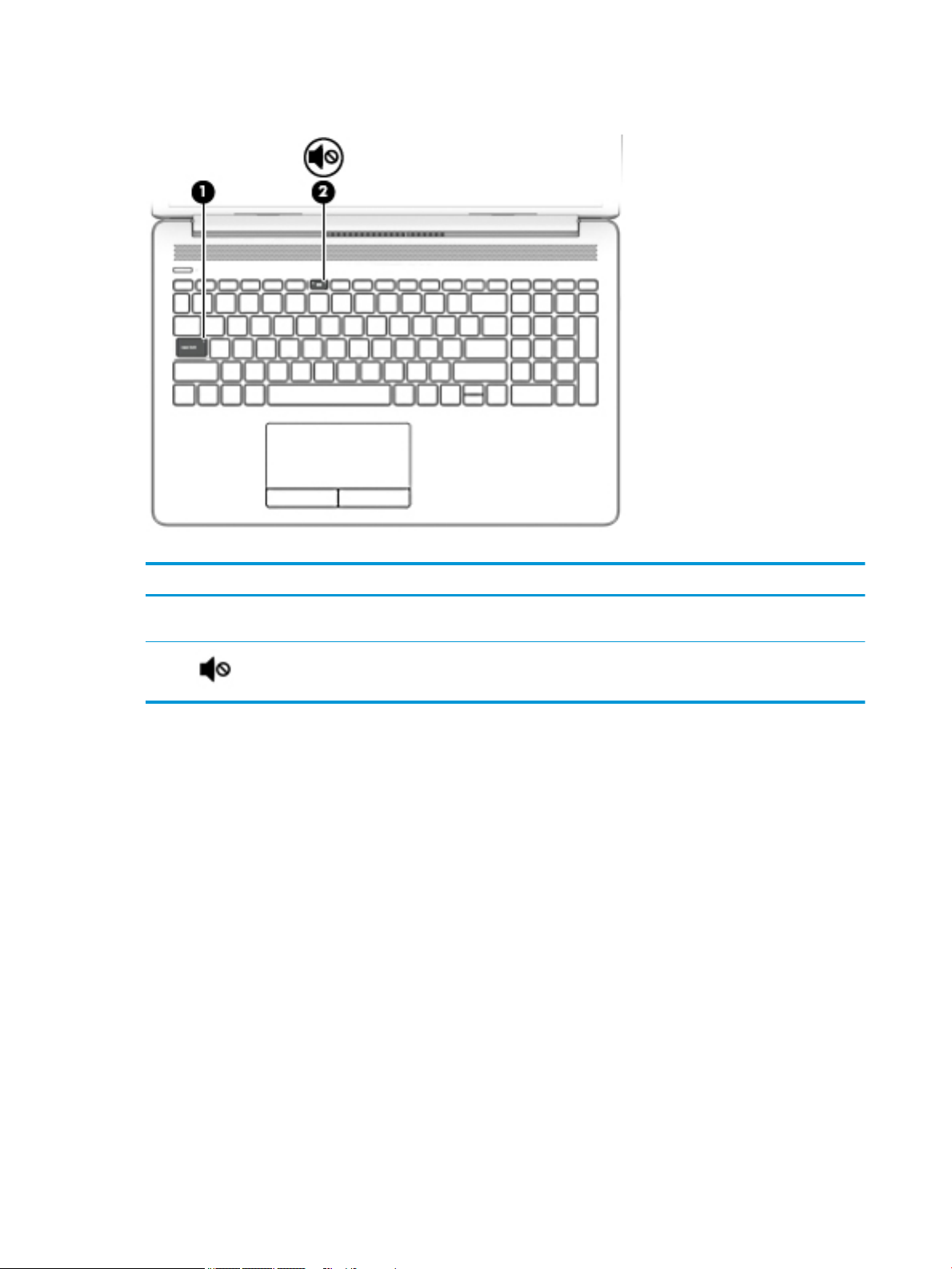
Lights
Table 2-5 Lights and their descriptions
Component Description
(1) Caps lock light On: Caps lock is on, which switches the key input to all capital
letters.
(2) Mute light ● Amber: Computer sound is o.
● O: Computer sound is on.
10 Chapter 2 Getting to know your computer
Page 21
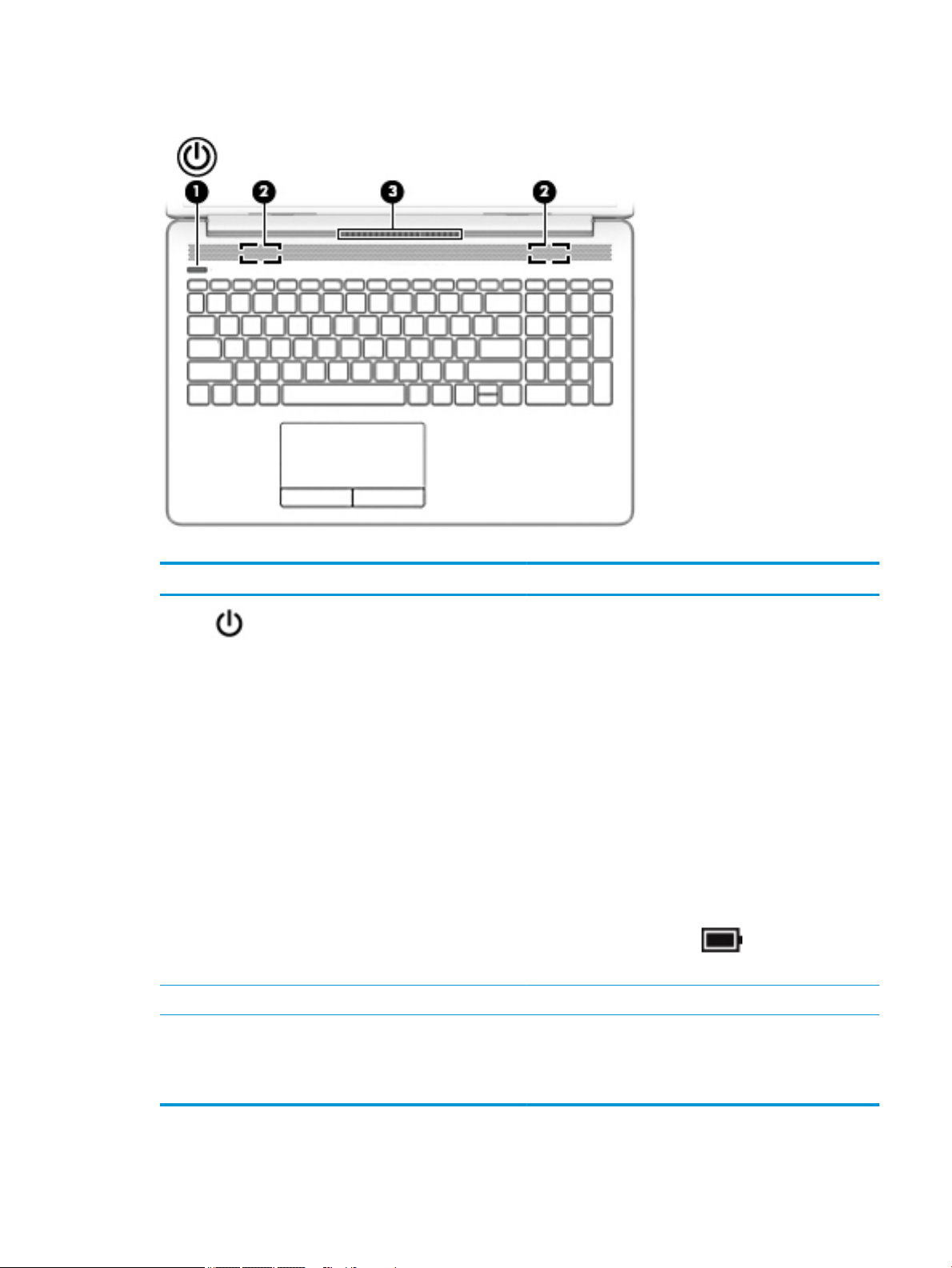
Button, speakers, and vent
Table 2-6 Button, speakers, and vent and their descriptions
Component Description
(1) Power button ● When the computer is o, press the button to turn on the
computer.
● When the computer is on, press the button briey to
initiate Sleep.
● When the computer is in the Sleep state, press the button
briey to exit Sleep.
● When the computer is in Hibernation, press the button
briey to exit Hibernation.
CAUTION: Pressing and holding down the power button results
in the loss of unsaved information.
If the computer has stopped responding and shutdown
procedures are ineective, press and hold the power button
down for at least 5 seconds to turn o the computer.
To learn more about your power settings, see your power
options:
▲ Right-click the Power icon , and then select Power
Options.
(2) Speakers (2) Produce sound.
(3) Vent Enables airow to cool internal components.
NOTE: The computer fan starts up automatically to cool
internal components and prevent overheating. It is normal for
the internal fan to cycle on and o during routine operation.
Keyboard area 11
Page 22
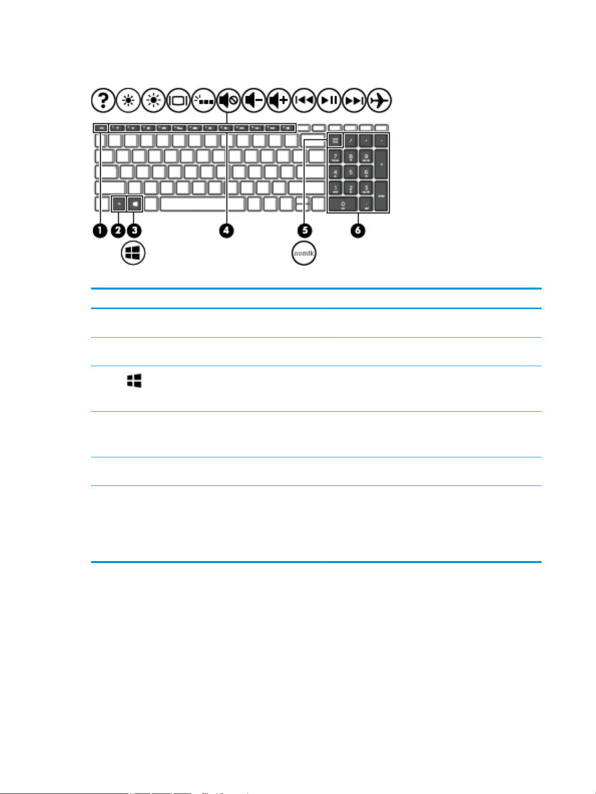
Special keys
Table 2-7 Special keys and their descriptions
Component Description
(1) esc key Displays system information when pressed in combination with
(2) fn key Executes specic functions when pressed in combination with
the fn key.
another key.
(3) Windows key Opens the Start menu.
NOTE: Pressing the Windows key again will close the Start
menu.
(4) Action keys Execute frequently used system functions.
NOTE: On select products, the f5 action key turns the keyboard
backlight feature o or on.
(5) num lock key Alternates between the navigational and numeric functions on
the integrated numeric keypad.
(6) Integrated numeric keypad A separate keypad to the right of the alphabet keyboard. When
num lock is pressed, the keypad can be used like an external
numeric keypad.
NOTE: If the keypad function is active when the computer is
turned o, that function is reinstated when the computer is
turned back on.
12 Chapter 2 Getting to know your computer
Page 23
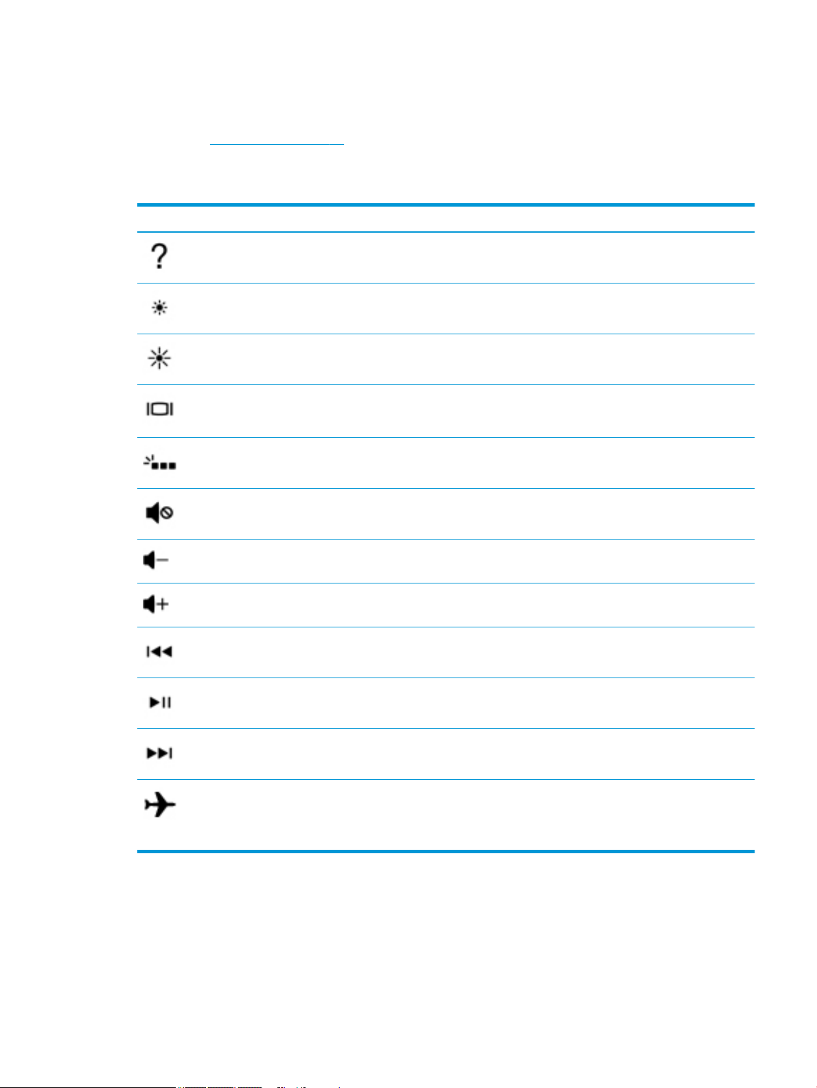
Action keys
An action key performs the function indicated by the icon on the key. To determine which keys are on your
product, see Special keys on page 12.
▲ To use an action key, press and hold the key.
Table 2-8 Actions keys and their descriptions
Icon Description
Opens the “How to get help in Windows 10” webpage.
Decreases the screen brightness incrementally as long as you hold down the key.
Increases the screen brightness incrementally as long as you hold down the key.
Switches the screen image between display devices connected to the system. For example, if a monitor is
connected to the computer, repeatedly pressing this key alternates the screen image from the computer
display to the monitor display to a simultaneous display on both the computer and the monitor.
Turns the keyboard backlight o or on.
NOTE: To conserve battery power, turn o this feature.
Mutes or restores speaker sound.
Decreases speaker volume incrementally while you hold down the key.
Increases speaker volume incrementally while you hold down the key.
Plays the previous track of an audio CD or the previous section of a DVD or a Blu-ray Disc (BD).
Starts, pauses, or resumes playback of an audio CD, a DVD, or a BD.
Plays the next track of an audio CD or the next section of a DVD or a BD.
Turns the airplane mode and wireless feature on or o.
NOTE: The airplane mode key is also referred to as the wireless button.
NOTE: A wireless network must be set up before a wireless connection is possible.
Keyboard area 13
Page 24
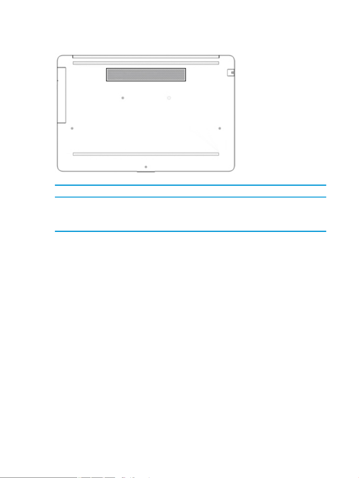
Bottom
Table 2-9 Bottom component and its description
Component Description
Vent Enables airow to cool internal components.
NOTE: The computer fan starts up automatically to cool internal
components and prevent overheating. It is normal for the internal fan
to cycle on and o during routine operation.
14 Chapter 2 Getting to know your computer
Page 25
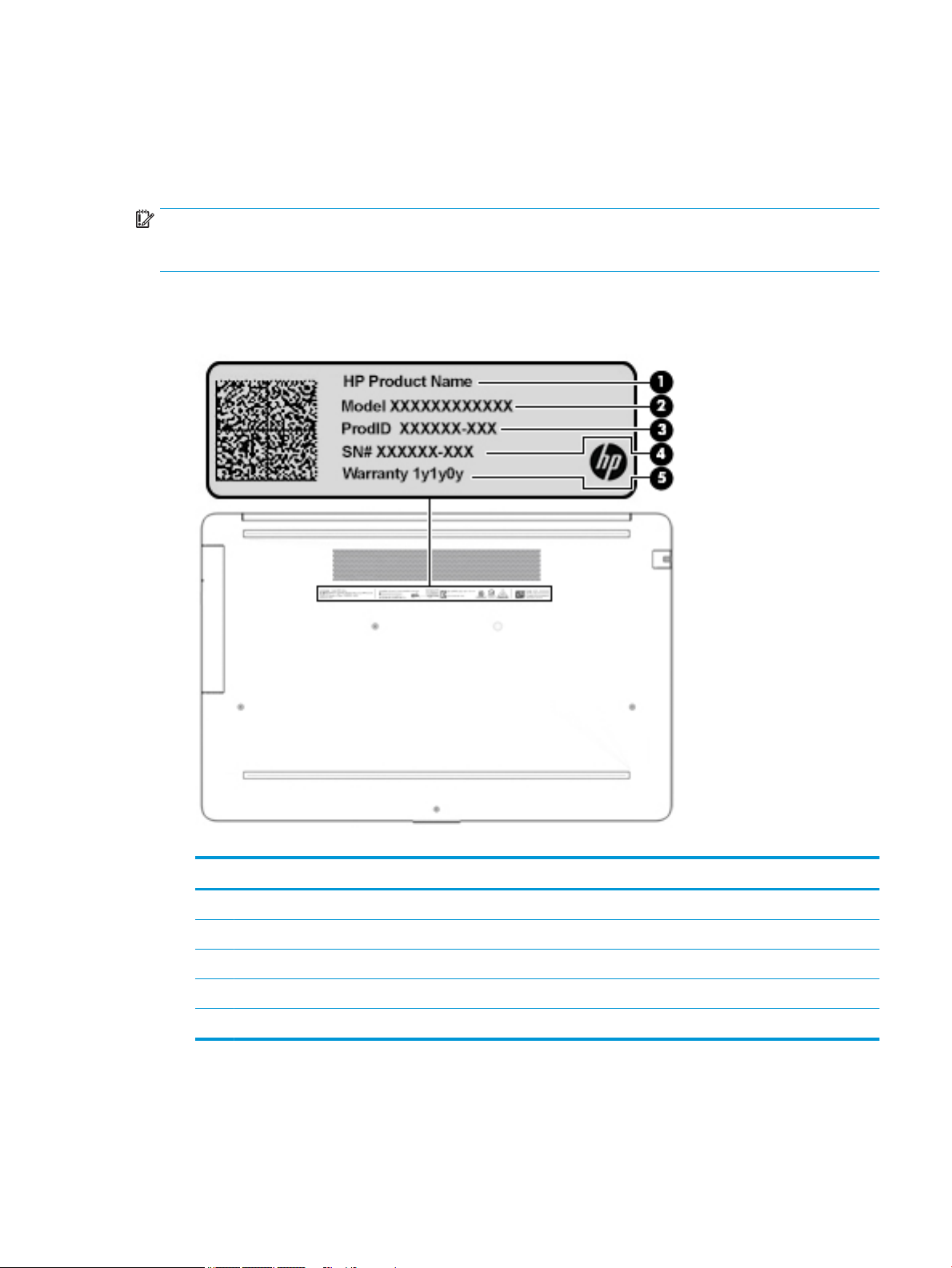
Labels
The labels axed to the computer provide information you may need when you troubleshoot system
problems or travel internationally with the computer. Labels may be in paper form or imprinted on the
product.
IMPORTANT: Check the following locations for the labels described in this section: the bottom of the
computer, inside the battery bay, under the service door, on the back of the display, or on the bottom of a
tablet kickstand.
● Service label—Provides important information to identify your computer. When contacting support, you
may be asked for the serial number, the product number, or the model number. Locate this information
before you contact support.
Table 2-10 Service label components
Component
(1) HP product name
(2) Model number
(3) Product ID
(4) Serial number
(5) Warranty period
● Regulatory label(s)—Provide(s) regulatory information about the computer.
● Wireless certication label(s)—Provide(s) information about optional wireless devices and the approval
markings for the countries or regions in which the devices have been approved for use.
Labels 15
Page 26
3 Illustrated parts catalog
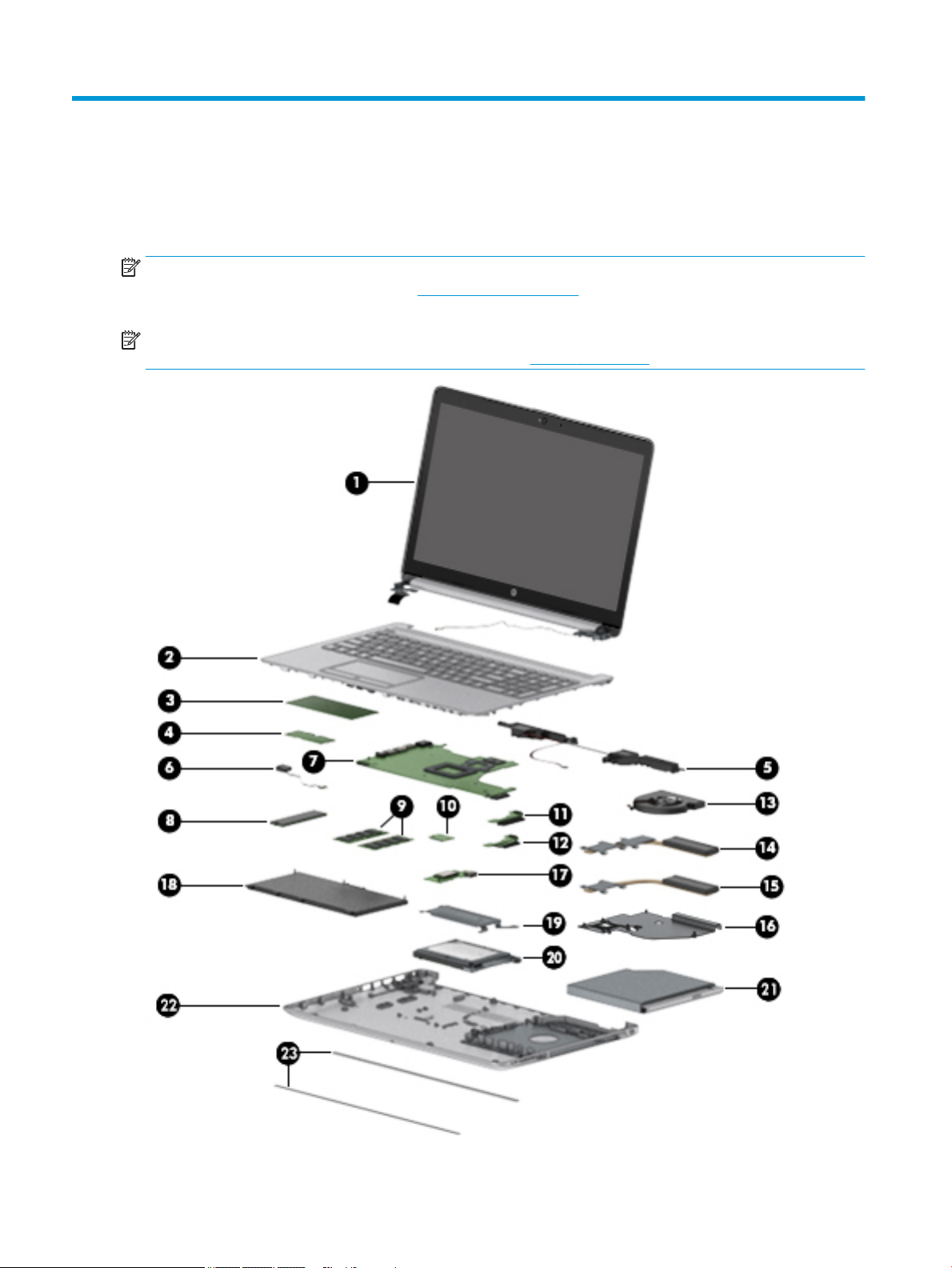
Computer major components
NOTE: HP continually improves and changes product parts. For complete and current information on
supported parts for your computer, go to http://partsurfer.hp.com, select your country or region, and then
follow the on-screen instructions.
NOTE: Details about your computer, including model, serial number, product key, and length of warranty,
are on the service tag at the bottom of your computer. See Labels on page 15 for details.
16 Chapter 3 Illustrated parts catalog
Page 27

Table 3-1 Computer major components and their descriptions
Item Component Spare part
number
(1) Display
NOTE: Displays are not spared as whole units. Display subcomponent spare parts are available. For
spare part information, see Display assembly subcomponents on page 22.
(2) Top cover/keyboard
NOTE: For a detailed list of country codes, see Top cover with keyboard on page 76.
Keyboard, no backlight, jet black L20387-xx1
Keyboard, no backlight, full-featured models, snow white L20388-xx1
Keyboard, no backlight, defeatured models, snow white L23066-xx1
Keyboard, no backlight, ash silver L20386-xx1
Keyboard, backlit, ash silver (available only with -001 United States, -002 India, and -DB1 Canadian
French keyboards)
Keyboard, no backlight, iridescent pale rose gold (available only with -001 United States keyboards) L28504-001
Keyboard, backlit, iridescent pale rose gold (available only with -001 United States keyboards) L28505-001
Keyboard, no backlight, iridescent ceramic white (available only with -001 United States keyboards) L28506-001
Keyboard, backlit, iridescent ceramic white (available only with -001 United States keyboards) L28507-001
Keyboard, no backlight, ocean teal (available only with -001 United States keyboards) L31735-001
Keyboard, no backlight, Real Tree (available only with -001 United States keyboards) L31736-001
Not spared
L23074-xx1
Keyboard, no backlight, natural silver (available only with -002 India keyboards) L32368-002
Keyboard, backlit, ocean teal (available only with -001 United States keyboards) L32863-001
Keyboard, backlit, natural silver (available only with -002 India keyboards) L32864-002
(3) TouchPad module L20449-001
(4) TouchPad button board not spared
(5) Speakers (include cable) L20453-001
(6) Power connector cable (DC-in) L20475-001
(7) System board
NOTE: All system board spare part kits include replacement thermal material.
All system boards use the following part numbers:
xxxxxx-001: Non-Windows operating systems
xxxxxx-601: Windows operating system
For use in models with discrete graphics memory:
● AMD Athlon 300U processor and Radeon 530 graphics L53469-xx1
● AMD Ryzen 3-3200U processor and Radeon 530 graphics L46517-xx1
● AMD Ryzen 3-2200U processor and Radeon 530 graphics L20668-xx1
● AMD A9-9425 processor and Radeon 530 graphics L46513-xx1
Computer major components 17
Page 28

Table 3-1 Computer major components and their descriptions (continued)
Item Component Spare part
number
● AMD A9-9425 processor and Radeon 520 graphics L20480-xx1
● AMD A6-9225 processor and Radeon 530 graphics L46514-xx1
● AMD A6-9225 processor and Radeon 520 graphics L20481-xx1
For use in models with UMA graphics memory:
● AMD Ryzen 7-3700U processor L51325-xx1
● AMD Ryzen 5-3500U processor L46515-xx1
● AMD Ryzen 3-3200U processor L46516-xx1
● AMD Ryzen 5-2500U processor L20664-xx1
● AMD Ryzen 3-2300U processor L20665-xx1
● AMD Ryzen 3-2200U processor L20666-xx1
● AMD A9-9425 processor L20477-xx1
● AMD A6-9225 processor L20478-xx1
● AMD A4-9125 processor L31720-xx1
● AMD E2-9000e processor L20479-xx1
(8) Solid-state drive
NOTE: For spare part information, see Mass storage devices on page 26.
(9) Memory modules (2400 MHz DDR4)
8 GB 862398-855
4 GB 862397-855
(10) WLAN module
Realtek RTL8822BE 802.11ac 2 × 2 Wi-Fi + Bluetooth 4.2 Combo Adapter (MU-MIMO supported) 924813-855
Realtek RTL8821CE 802.11ac 1 × 1 Wi-Fi + Bluetooth 4.2 Combo Adapter (MU-MIMO supported) L17365-005
Realtek RTL8723DE 802.11bgn 1 × 1 Wi-Fi + Bluetooth 4.2 Combo Adapter L21480-005
(11) Hard drive connector board L20454-001
(12) Solid-state drive connector board L20457-001
(13) Fan
For use in models with discrete graphics L20473-001
For use in models with UMA graphics L20474-001
(14) Heat sink for use in models with AMD Ryzen processors and discrete graphics L20482-001
Heat sink for use in models with AMD A6/A9 processors and discrete graphics L20484-001
(15) Heat sink for use in models with AMD Ryzen processors and integrated UMA graphics L20483-001
Heat sink for use in models with AMD A6/A9 processors and integrated UMA graphics L20491-001
(16) Heat sink for use in fanless models with AMD E2-9000e processors L20494-001
18 Chapter 3 Illustrated parts catalog
Page 29

Table 3-1 Computer major components and their descriptions (continued)
Item Component Spare part
number
(17) USB/card reader board
The USB/card reader board cable is available using spare part number L20452-001.
(18) Battery (3-cell, 41 Whr) L11119-855
(19) Solid-state drive bracket L20458-001
(20) Hard drive
NOTE: For spare part information, see Mass storage devices on page 26.
(21) DVD+/-RW Double-Layer Writer L20485-001
(22) Bottom cover
For use in models with an optical drive
● Snow white L20389-001
● Jet black L20390-001
● Natural silver L20391-001
● Pale gold L20392-001
● Twilight blue L20393-001
● Scarlet red L20397-001
● Smoke gray L20395-001
L20448-001
● Maroon burgundy L20398-001
● Iridescent pale rose gold L28510-001
● Iridescent ceramic white L28512-001
● Ocean teal L31725-001
● Real Tree L31726-001
● Berry mauve; Pattern: mesh knit L50283-001
● Chalkboard gray; Pattern: mesh knit L50284-001
● Jet black; Pattern: mesh knit L50285-001
● Lumiere blue; Pattern: mesh knit L50286-001
● Snow white; Pattern: mesh knit L50288-001
For use in models without an optical drive
● Snow white L20399-001
● Jet black L20400-001
● Natural silver L20401-001
● Pale gold L20402-001
● Pale rose gold L57161-001
● Twilight blue L20403-001
Computer major components 19
Page 30

Table 3-1 Computer major components and their descriptions (continued)
Item Component Spare part
number
● Scarlet red L20405-001
● Smoke gray L20404-001
● Iridescent pale rose gold L28511-001
● Iridescent ceramic white L28513-001
● Maroon burgundy L31719-001
● Berry mauve: Pattern: mesh knit L50289-001
● Chalkboard gray: Pattern: mesh knit L50290-001
● Jet black; Pattern: mesh knit L50291-001
● Lumiere blue; Pattern: mesh knit L50292-001
● Snow white; Pattern: mesh knit L50293-001
(23) Front rubber feet
Pale gold L20408-001
Pale rose gold L57162-001
Iridescent pale rose gold L28518-001
Scarlet red L20411-001
Twilight blue L20409-001
Maroon burgundy L20412-001
Dark ash silver L20406-001
Asteroid silver L20407-001
Ocean teal L31731-001
Real Tree L31732-001
Berry mauve; Pattern: mesh knit L50314-001
Lumiere blue; Pattern: mesh knit L50317-001
(23) Rear rubber feet:
Pale gold L20415-001
Pale rose gold L57163-001
Iridescent pale rose gold L28519-001
Scarlet red L20418-001
Twilight blue L20416-001
Maroon burgundy L20419-001
Dark ash silver L20413-001
Asteroid silver L20414-001
Ocean teal L31733-001
20 Chapter 3 Illustrated parts catalog
Page 31
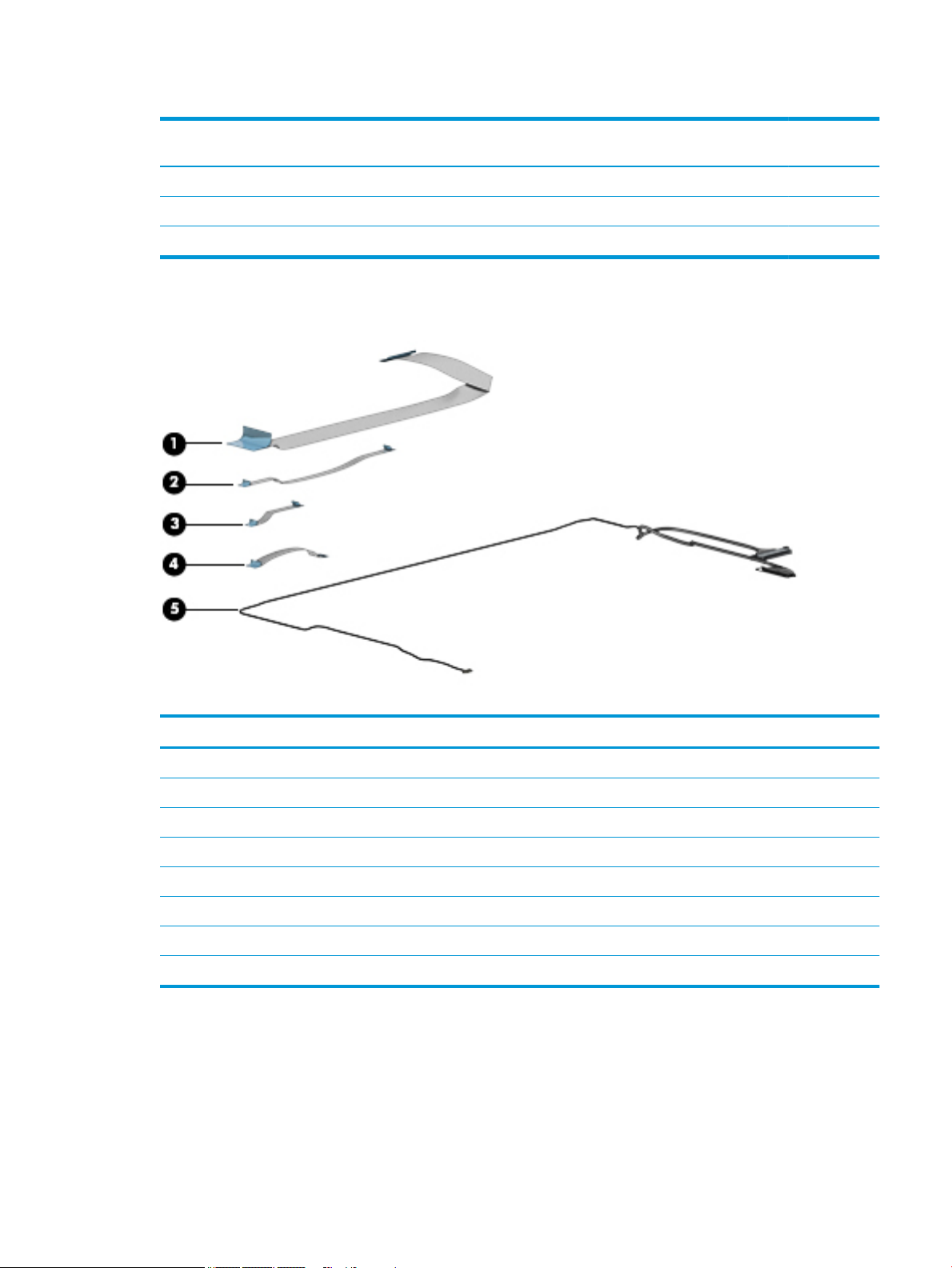
Cables
Table 3-1 Computer major components and their descriptions (continued)
Item Component Spare part
number
Real Tree L31734-001
Berry mauve; Pattern: mesh knit L50320-001
Lumiere blue; Pattern: mesh knit L50323-001
Table 3-2 Cables and their descriptions
Item Component Spare part number
(1) USB/card reader board cable L20452-001
(2) TouchPad button board cable L20451-001
(3) TouchPad cable L20450-001
(4) Hard drive/solid-state drive cable L20456-001
(5) Display cable
Display cable, non-touch, HD L20443-001
Display cable, non-touch, FHD L23064-001
Display cable, touch, HD L20442-001
Cables 21
Page 32

Display assembly subcomponents
Table 3-3 Display components and their descriptions
Item Component Spare part number
(1) Hinge cover
Jet black L20423-001
Sparkling black L20427-001
Natural silver L20424-001
Pale gold L20425-001
Pale rose gold L57159-001
Iridescent pale rose gold L28516-001
Scarlet red L20430-001
Twilight blue L20426-001
Smoke gray L20428-001
Snow white (full-featured models) L20422-001
Snow white (defeatured) models L21306-001
22 Chapter 3 Illustrated parts catalog
Page 33

Table 3-3 Display components and their descriptions (continued)
Item Component Spare part number
Maroon burgundy L20431-001
Iridescent ceramic white L28517-001
Ocean teal L31729-001
Real Tree L31730-001
Berry mauve: Pattern: mesh knit L50294-001
Chalkboard gray: Pattern: mesh knit L50295-001
Lumiere blue; Pattern: mesh knit L50297-001
(2) Display bezel
Standard L20421-001
Real Tree L32367-001
(3) Display panel
HD, BrightView, non-touch L20379-001
HD, anti glare, non-touch L20378-001
HD, BrightView, touch-on panel (TOP) L20380-001
FHD, anti glare, non-touch L20376-001
FHD, anti glare, narrow bezel L20377-001
Miscellaneous Display Kit (includes gaskets [4] and rubber corner positioning tools [4]; not
illustrated)
Display panel stretchable adhesive tape (not illustrated) L29080-001
(4) Hinge Kit (includes left and right hinges) L20420-001
(5) Display cable
Non-touch, HD L20443-001
Non-touch, FHD L23064-001
Touch, HD L20442-001
(6) Camera module
HD camera L20447-001
VGA camera L20446-001
(7) WLAN antenna cable
Single antenna L20445-001
Single antenna, narrow bezel L23060-001
Dual antennas L20444-001
L23065-001
Dual antennas, narrow bezel L23059-001
(8) Back cover
Jet black L20433-001
Display assembly subcomponents 23
Page 34

Table 3-3 Display components and their descriptions (continued)
Item Component Spare part number
Jet black (narrow bezel models) L23061-001
Sparkling black L20437-001
Natural silver L20434-001
Natural silver (narrow bezel models) L23062-001
Pale gold L20435-001
Pale rose gold L57158-001
Scarlet red L20440-001
Twilight blue L20436-001
Smoke gray L20438-001
Smoke gray (narrow bezel models) L23063-001
Snow white (full-featured models L20432-001
Snow white (defeatured models) L21307-001
Maroon burgundy L20441-001
Iridescent pale rose gold L28508-001
Iridescent ceramic white L28509-001
Ocean teal L31723-001
Real Tree L31724-001
Berry mauve; Pattern: mesh knit L50301-001
Chalkboard gray; Pattern: mesh knit L50302-001
Jet black; Pattern: mesh knit L50303-001
Lumiere blue; Pattern: mesh knit L50304-001
Snow white; Pattern: mesh knit; for use in defeatured models L50306-001
Snow white; Pattern: mesh knit; for use in full-featured models L50307-001
Chalkboard gray; Pattern: mesh knit L54498-001
Jet black; Pattern: mesh knit; for use on narrow bezel models L54499-001
Miscellaneous parts
3-4 Miscellaneous parts and their descriptions
Table
Component Spare part number
AC adapter
65 W AC adapter, nPFC, 4.5 mm 710412-001
65 W AC adapter, nPFC, SMART, RC, 4.5 mm, EM 913691-850
65 W AC adapter, nPFC, 4.5 mm for use in Argentina 710340-850
24 Chapter 3 Illustrated parts catalog
Page 35

Table 3-4 Miscellaneous parts and their descriptions (continued)
Component Spare part number
45 W AC adapter, nPFC, SMART, RC, 4.5 mm, non-slim 741727-001
45 W AC adapter, nPFC, SMART, RC, 4.5 mm for use in Argentina 741553-852
Power cord, C5, conventional, 1.0 m
For use in Argentina L19357-001
For use in Australia L19358-001
For use in Denmark L19360-001
For use in Europe L19361-001
For use in India L19363-001
For use in Israel L19362-001
For use in Italy L19364-001
For use in Japan L19365-001
For use in North America L19367-001
For use in the People’s Republic of China L19368-001
For use in South Africa L19369-001
For use in South Korea L19366-001
For use in Switzerland L19370-001
For use in Taiwan L19372-001
For use in Thailand L19371-001
For use in the United Kingdom L19373-001
Screw Kit L20476-001
HP Rugged Bluetooth Speaker, black 900777-001
HP Sleeve, Chroma, Geo L07806-101
HP Sleeve, neoprene, black L43042-001
Mouse, X3000 wireless 684978-001
Miscellaneous parts 25
Page 36

Mass storage devices
Table 3-5 Mass storage devices and their descriptions
Item Component Spare part number
(1) DVD+/-RW Double-Layer Writer L20485-001
(2) Optical drive bezel
Natural silver L20462-001
Pale gold L20463-001
Pale rose gold L57160-001
Iridescent pale rose gold L28514-001
Scarlet red L20467-001
Smoke gray L20465-001
Twilight blue L20464-001
Maroon burgundy L20468-001
Jet black L20461-001
Snow white L20460-001
Iridescent ceramic white L28515-001
Ocean teal L31727-001
Real Tree L31728-001
Berry mauve: Pattern: mesh knit L50308-001
Chalkboard gray: Pattern: mesh knit L50309-001
Jet black; Pattern: mesh knit L50310-001
26 Chapter 3 Illustrated parts catalog
Page 37

Table 3-5 Mass storage devices and their descriptions (continued)
Item Component Spare part number
Lumiere blue; Pattern: mesh knit L50311-001
Snow white; Pattern: mesh knit L50313-001
(3) Optical drive bracket L20459-001
(4) Hard drive, 7 mm
2 TB, 5400 rpm 912487-855
1 TB, 5400 rpm 762990-005
500 GB, 5400 rpm 778186-005
(5) Hard drive bracket L20455-001
(6) Hard drive connector board L20454-001
(7) Hard drive/solid-state drive cable L20456-001
(8) Solid-state drive bracket L20458-001
(9) Solid-state drive connector board L20457-001
(10) Solid-state drive (M.2)
256 GB, PCIe, NVMe L20384-001
256 GB, SATA-3, TLC L20382-001
128 GB, SATA-3, TLC L20381-001
Mass storage devices 27
Page 38

4 Removal and replacement procedures
preliminary requirements
Tools required
You will need the following tools to complete the removal and replacement procedures:
● Non-conductive, non-marking plastic tool
● Magnetic Phillips P1 screwdriver
Service considerations
The following sections include some of the considerations that you must keep in mind during disassembly
and assembly procedures.
NOTE: As you remove each subassembly from the computer, place the subassembly (and all accompanying
screws) away from the work area to prevent damage.
Plastic parts
IMPORTANT: Using excessive force during disassembly and reassembly can damage plastic parts.
Cables and connectors
IMPORTANT: When servicing the computer, be sure that cables are placed in their proper locations during
the reassembly process. Improper cable placement can damage the computer.
Cables must be handled with extreme care to avoid damage. Apply only the tension required to unseat or seat
the cables during removal and insertion. Handle cables by the connector whenever possible. In all cases, avoid
bending, twisting, or tearing cables. Be sure that cables are routed in such a way that they cannot be caught
or snagged by parts being removed or replaced. Handle ex cables with extreme care; these cables tear
easily.
28 Chapter 4 Removal and replacement procedures preliminary requirements
Page 39

Drive handling
IMPORTANT: Drives are fragile components that must be handled with care. To prevent damage to the
computer, damage to a drive, or loss of information, observe these precautions:
Before removing or inserting a hard drive, shut down the computer. If you are unsure whether the computer is
o or in Hibernation, turn the computer on, and then shut it down through the operating system.
Before handling a drive, be sure that you are discharged of static electricity. While handling a drive, avoid
touching the connector.
Before removing an optical drive, be sure that a disc is not in the drive and be sure that the optical drive tray is
closed.
Handle drives on surfaces covered with at least one inch of shock-proof foam.
Avoid dropping drives from any height onto any surface.
After removing a hard drive or an optical drive, place it in a static-proof bag.
Avoid exposing an internal hard drive to products that have magnetic elds, such as monitors or speakers.
Avoid exposing a drive to temperature extremes or liquids.
If a drive must be mailed, place the drive in a bubble pack mailer or other suitable form of protective
packaging and label the package “FRAGILE.”
Workstation guidelines
Follow these grounding workstation guidelines:
● Cover the workstation with approved static-shielding material.
● Use a wrist strap connected to a properly grounded work surface and use properly grounded tools and
equipment.
● Use conductive eld service tools, such as cutters, screw drivers, and vacuums.
● When xtures must directly contact dissipative surfaces, use xtures made only of static-safe materials.
● Keep the work area free of nonconductive materials, such as ordinary plastic assembly aids
and Styrofoam.
● Handle ESD-sensitive components, parts, and assemblies by the case or PCM laminate. Handle these
items only at static-free workstations.
● Avoid contact with pins, leads, or circuitry.
● Turn o power and input signals before inserting or removing connectors or test equipment.
Electrostatic discharge information
A sudden discharge of static electricity from your nger or other conductor can destroy static-sensitive
devices or microcircuitry. Often the spark is neither felt nor heard, but damage occurs. An electronic device
exposed to electrostatic discharge (ESD) may not appear to be aected at all and can work perfectly
throughout a normal cycle. The device may function normally for a while, but it has been degraded in the
internal layers, reducing its life expectancy.
Networks built into many integrated circuits provide some protection, but in many cases, the discharge
contains enough power to alter device parameters or melt silicon junctions.
Electrostatic discharge information 29
Page 40

IMPORTANT: To prevent damage to the device when you are removing or installing internal components,
observe these precautions:
Keep components in their electrostatic-safe containers until you are ready to install them.
Before touching an electronic component, discharge static electricity by using the guidelines described in this
section.
Avoid touching pins, leads, and circuitry. Handle electronic components as little as possible.
If you remove a component, place it in an electrostatic-safe container.
Generating static electricity
Note the following:
● Dierent activities generate dierent amounts of static electricity.
● Static electricity increases as humidity decreases.
Table 4-1 Static electricity occurrence based on activity and humidity
Relative humidity
Event 55% 40% 10%
Walking across carpet
Walking across vinyl oor
Motions of bench worker
Removing DIPs from plastic tube
Removing DIPs from vinyl tray
Removing DIPs from Styrofoam
Removing bubble pack from PCB
Packing PCBs in foam-lined box
Electronic components are then multi-packaged inside plastic tubes, trays, or Styrofoam.
NOTE: As little as 700 volts can degrade a product.
Preventing electrostatic damage to equipment
Many electronic components are sensitive to ESD. Circuitry design and structure determine the degree of
sensitivity. The following packaging and grounding precautions are necessary to prevent static electricity
damage to electronic components.
● To avoid hand contact, transport products in static-safe containers such as tubes, bags, or boxes.
7,500 V
3,000 V
400 V
400 V
2,000 V
3,500 V
7,000 V
5,000 V
15,000 V
5,000 V
800 V
700 V
4,000 V
5,000 V
20,000 V
11,000 V
35,000 V
12,000 V
6,000 V
2,000 V
11,500 V
14,500 V
26,500 V
21,000 V
● Protect all electrostatic parts and assemblies with conductive or approved containers or packaging.
● Keep electrostatic-sensitive parts in their containers until they arrive at static-free stations.
● Place items on a grounded surface before removing them from their container.
● Always be properly grounded when touching a sensitive component or assembly.
30 Chapter 4 Removal and replacement procedures preliminary requirements
Page 41

● Avoid contact with pins, leads, or circuitry.
● Place reusable electrostatic-sensitive parts from assemblies in protective packaging or conductive
foam.
Personal grounding methods and equipment
Use the following equipment to prevent static electricity damage to electronic components:
● Wrist straps are exible straps with a maximum of one-megohm ± 10% resistance in the ground cords.
To provide proper ground, a strap must be worn snug against bare skin. The ground cord must be
connected and t snugly into the banana plug connector on the grounding mat or workstation.
● Heel straps/Toe straps/Boot straps can be used at standing workstations and are compatible with
most types of shoes or boots. On conductive oors or dissipative oor mats, use them on both feet with
a maximum of one-megohm ± 10% resistance between the operator and ground.
Table 4-2 Static shielding protection levels
Static shielding protection levels
Method Voltage
Antistatic plastic
Carbon-loaded plastic
Metallized laminate
Grounding the work area
To prevent static damage at the work area, use the following precautions:
● Cover the work surface with approved static-dissipative material. Provide a wrist strap connected to the
work surface and properly grounded tools and equipment.
● Use static-dissipative mats, foot straps, or air ionizers to give added protection.
● Handle electrostatic sensitive components, parts, and assemblies by the case or PCB laminate. Handle
them only at static-free work areas.
● Turn o power and input signals before inserting and removing connectors or test equipment.
● Use xtures made of static-safe materials when xtures must directly contact dissipative surfaces.
● Keep work area free of nonconductive materials such as ordinary plastic assembly aids and Styrofoam.
● Use eld service tools, such as cutters, screwdrivers, and vacuums, that are conductive.
Recommended materials and equipment
1,500
7,500
15,000
Materials and equipment that are recommended for use in preventing static electricity include:
● Antistatic tape
● Antistatic smocks, aprons, or sleeve protectors
● Conductive bins and other assembly or soldering aids
● Conductive foam
● Conductive tabletop workstations with ground cord of one-megohm +/- 10% resistance
● Static-dissipative table or oor mats with hard tie to ground
Electrostatic discharge information 31
Page 42

● Field service kits
● Static awareness labels
● Wrist straps and footwear straps providing one-megohm +/- 10% resistance
● Material handling packages
● Conductive plastic bags
● Conductive plastic tubes
● Conductive tote boxes
● Opaque shielding bags
● Transparent metallized shielding bags
● Transparent shielding tubes
Packaging and transporting guidelines
Follow these grounding guidelines when packaging and transporting equipment:
● To avoid hand contact, transport products in static-safe tubes, bags, or boxes.
● Protect ESD-sensitive parts and assemblies with conductive or approved containers or packaging.
● Keep ESD-sensitive parts in their containers until the parts arrive at static-free workstations.
● Place items on a grounded surface before removing items from their containers.
● Always be properly grounded when touching a component or assembly.
● Store reusable ESD-sensitive parts from assemblies in protective packaging or nonconductive foam.
● Use transporters and conveyors made of antistatic belts and roller bushings. Be sure that mechanized
equipment used for moving materials is wired to ground and that proper materials are selected to avoid
static charging. When grounding is not possible, use an ionizer to dissipate electric charges.
32 Chapter 4 Removal and replacement procedures preliminary requirements
Page 43

5 Removal and replacement procedures for
Customer Self-Repair parts
This chapter provides removal and replacement procedures for Customer Self-Repair parts.
NOTE: The Customer Self-Repair program is not available in all locations. Installing a part not supported by
the Customer Self-Repair program may void your warranty. Check your warranty to determine if Customer
Self-Repair is supported in your location.
Component replacement procedures
NOTE: Details about your computer, including model, serial number, product key, and length of warranty,
are on the service tag at the bottom of your computer. See Labels on page 15 for details.
NOTE: HP continually improves and changes product parts. For complete and current information on
supported parts for your computer, go to http://partsurfer.hp.com, select your country or region, and then
follow the on-screen instructions.
Preparation for disassembly
See Removal and replacement procedures preliminary requirements on page 28 for initial safety procedures.
1. Turn o the computer. If you are unsure whether the computer is o or in Hibernation, turn the
computer on, and then shut it down through the operating system.
2. Disconnect the power from the computer by unplugging the power cord from the computer.
3. Disconnect all external devices from the computer.
Component replacement procedures 33
Page 44

Optical drive
Table 5-1 Optical drive part descriptions and part numbers
Description Spare part number
DVD+/-RW Double-Layer Writer L20485-001
Optical drive bracket L20459-001
Optical drive bezel
Natural silver L20462-001
Pale gold L20463-001
Pale rose gold L57160-001
Iridescent pale rose gold L28514-001
Scarlet red L20467-001
Smoke gray L20465-001
Twilight blue L20464-001
Maroon burgundy L20468-001
Jet black L20461-001
Snow white L20460-001
Iridescent ceramic white L28515-001
Ocean teal L31727-001
Real Tree L31728-001
Berry mauve: Pattern: mesh knit L50308-001
Chalkboard gray: Pattern: mesh knit L50309-001
Jet black; Pattern: mesh knit L50310-001
Lumiere blue; Pattern: mesh knit L50311-001
Snow white; Pattern: mesh knit L50313-001
Before removing the optical drive, follow these steps:
▲ Prepare the computer for disassembly (Preparation for disassembly on page 33).
Remove the optical drive:
1. Remove the Phillips M2.5 × 9.0 screw (1) that secures the drive to the computer.
34 Chapter 5 Removal and replacement procedures for Customer Self-Repair parts
Page 45
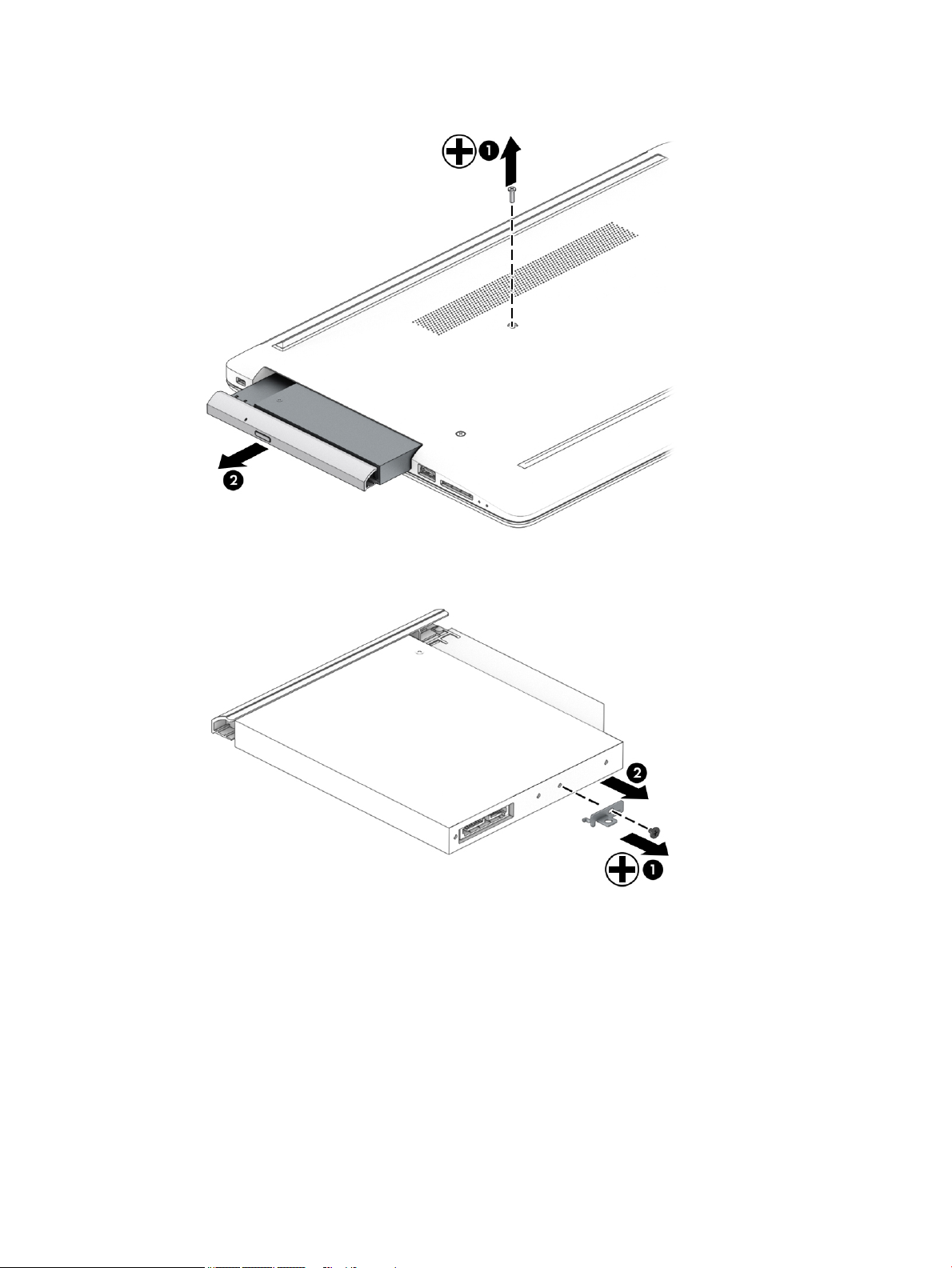
2. Slide the optical drive out of the computer (2).
3. If it necessary to remove the bracket from the rear of the optical drive, remove the Phillips M2.0 × 3.0
screw (1), and the remove the bracket from the drive (2).
4. If it necessary to remove the bezel from the front of the optical drive:
a. Insert a paper clip into the release hole on the front of the bezel (1). The left side of the bezel
rotates outward (2).
b. Press the tab to release the bezel from the drive (3).
c. Rotate the side of the bezel (4), and then remove it (5).
Component replacement procedures 35
Page 46

Reverse this procedure to reassemble and install the optical drive.
36 Chapter 5 Removal and replacement procedures for Customer Self-Repair parts
Page 47

6 Removal and replacement procedures for
authorized service provider parts
This chapter provides removal and replacement procedures for Authorized Service Provider only parts.
IMPORTANT: Components described in this chapter should only be accessed by an authorized service
provider. Accessing these parts can damage the computer or void the warranty.
Component replacement procedures
NOTE: Details about your computer, including model, serial number, product key, and length of warranty,
are on the service tag at the bottom of your computer. See Labels on page 15 for details.
NOTE: HP continually improves and changes product parts. For complete and current information on
supported parts for your computer, go to http://partsurfer.hp.com, select your country or region, and then
follow the on-screen instructions.
There are as many as 46 screws that must be removed, replaced, and/or loosened when servicing Authorized
Service Provider only parts. Make special note of each screw size and location during removal and
replacement.
Component replacement procedures 37
Page 48

Bottom cover
Table 6-1 Bottom cover descriptions and part numbers
Description Spare part number
Bottom cover for use in models with an optical drive
● Snow white L20389-001
● Jet black L20390-001
● Natural silver L20391-001
● Pale gold L20392-001
● Twilight blue L20393-001
● Scarlet red L20397-001
● Smoke gray L20395-001
● Maroon burgundy L20398-001
● Iridescent pale rose gold L28510-001
● Iridescent ceramic white L28512-001
● Ocean teal L31725-001
● Real tree L31726-001
● Berry mauve; Pattern: mesh knit L50283-001
● Chalkboard gray; Pattern: mesh knit L50284-001
● Jet black; Pattern: mesh knit L50285-001
● Lumiere blue; Pattern: mesh knit L50286-001
● Snow white; Pattern: mesh knit L50288-001
Bottom cover for use in models without an optical drive
● Snow white L20399-001
● Jet black L20400-001
● Natural silver L20401-001
● Pale gold L20402-001
● Pale rose gold L57161-001
● Twilight blue L20403-001
● Scarlet red L20405-001
● Smoke gray L20404-001
● Iridescent pale rose gold L28511-001
● Iridescent ceramic white L28513-001
● Maroon burgundy L31719-001
● Berry mauve; Pattern: mesh knit L50289-001
● Chalkboard gray; Pattern: mesh knit L50290-001
38 Chapter 6 Removal and replacement procedures for authorized service provider parts
Page 49

Table 6-1 Bottom cover descriptions and part numbers (continued)
Description Spare part number
● Jet black; Pattern: mesh knit L50291-001
● Lumiere blue; Pattern: mesh knit L50292-001
● Snow white; Pattern: mesh knit L50293-001
Front feet:
● Pale gold L20408-001
● Pale rose gold L57162-001
● Iridescent pale rose gold L28518-001
● Scarlet red L20411-001
● Twilight blue L20409-001
● Maroon burgundy L20412-001
● Dark ash silver L20406-001
● Asteroid silver L20407-001
● Ocean teal L31731-001
● Real Tree L31732-001
● Berry mauve; Pattern: mesh knit L50314-001
● Lumiere blue; Pattern: mesh knit L50317-001
Rear feet:
● Pale gold L20415-001
● Pale rose gold L57163-001
● Iridescent pale rose gold L28519-001
● Scarlet red L20418-001
● Twilight blue L20416-001
● Maroon burgundy L20419-001
● Dark ash silver L20413-001
● Asteroid silver L20414-001
● Ocean teal L31733-001
● Real Tree L31734-001
● Berry mauve; Pattern: mesh knit L50320-001
● Lumiere blue; Pattern: mesh knit L50323-001
1. Prepare the computer for disassembly (Preparation for disassembly on page 33).
2. Remove the optical drive (see Optical drive on page 34).
Remove the bottom cover:
Component replacement procedures 39
Page 50

1. Peel the rubber feet o the bottom of the computer (1).
2. Remove the 10 Phillips M2.5 × 9.0 screws that secure the bottom cover to the computer.
3. Starting near the middle, bottom of the bottom cover (1), pry the cover up to remove it (2).
Reverse this procedure to install the bottom cover.
40 Chapter 6 Removal and replacement procedures for authorized service provider parts
Page 51

Battery
Table 6-2 Battery description and part number
Description Spare part number
Battery (3-cell, 48 Whr) L11119-855
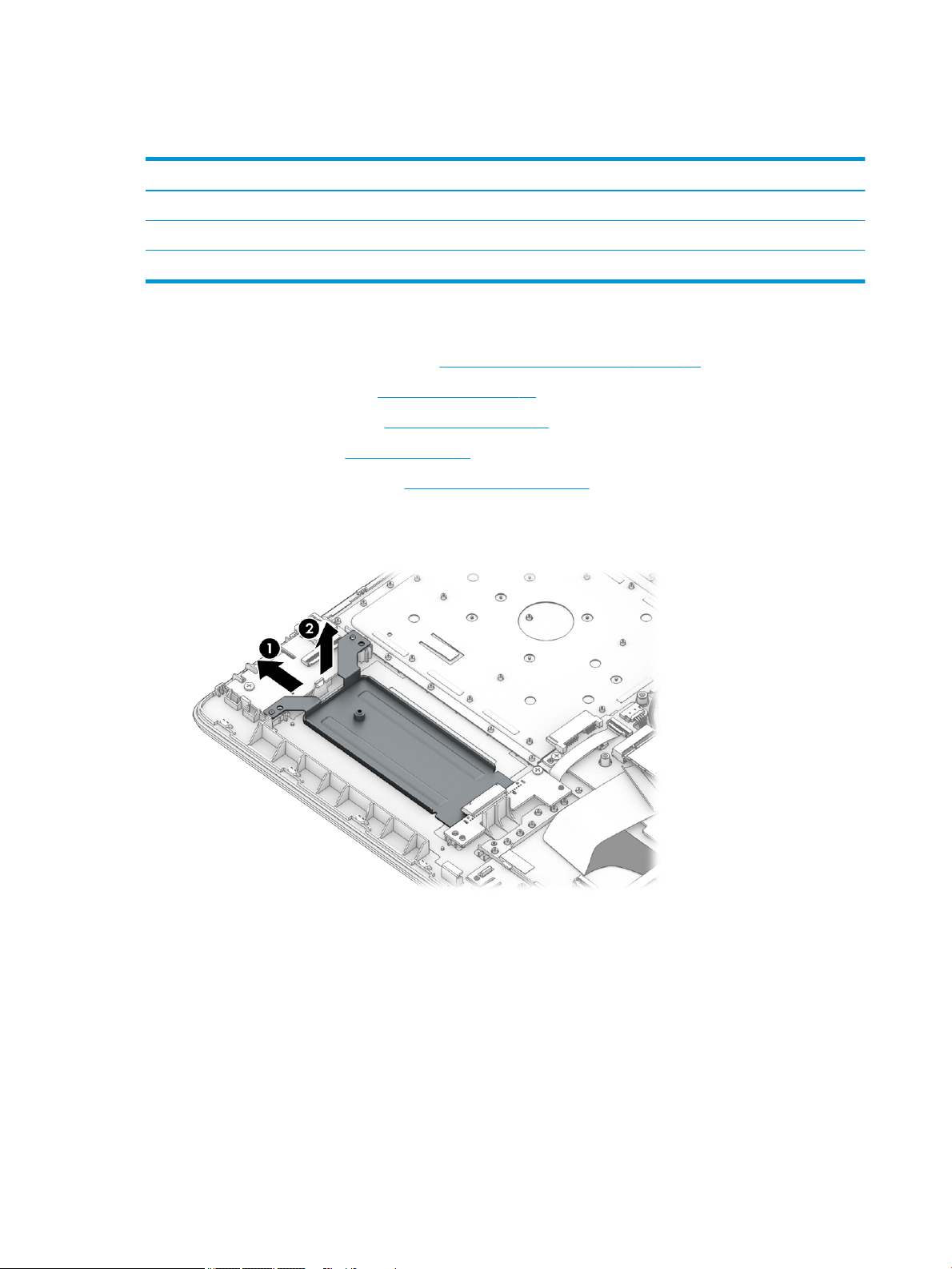
Before removing the battery, follow these steps:
1. Prepare the computer for disassembly (Preparation for disassembly on page 33).
2. Remove the optical drive (see Optical drive on page 34).
3. Remove the bottom cover (see Bottom cover on page 38).
Remove the battery:
1. Remove the three Phillips M2.0 × 8.0 screws (1) that secure the battery to the computer.
2. Remove the battery from the computer (2).
Reverse this procedure to install the battery.
When installing the battery, be sure to install screws in the proper locations. The following image shows the
locations around the battery that have holes but do NOT require screws.
Component replacement procedures 41
Page 52

42 Chapter 6 Removal and replacement procedures for authorized service provider parts
Page 53

Memory module
Table 6-3 Memory module descriptions and part numbers
Description Spare part number
Memory module, 8 GB 862398-855
Memory module, 4 GB 862397-855
Before removing the memory modules, follow these steps:
1. Prepare the computer for disassembly (Preparation for disassembly on page 33).
2. Remove the optical drive (see Optical drive on page 34).
3. Remove the bottom cover (see Bottom cover on page 38).
4. Remove the battery (see Battery on page 41).
Remove the memory modules:
1. Spread the two retention clips outward (1) until the memory module tilts up at a 45-degree angle.
2. Grasp the edge of the memory module (2), and then gently pull the module out of the slot. Use the same
procedure to remove both memory modules.
CAUTION: To prevent damage to the memory module, hold the memory module by the edges only. Do
not touch the components on the memory module.
To protect a memory module after removal, place it in an electrostatic-safe container.
Install the memory modules:
IMPORTANT: To prevent damage to the memory module, hold the memory module by the edges only. Do
not touch the components on the memory module. Do not bend the memory module.
1. Align the notched edge of the memory module with the tab in the memory module slot (1).
2. Press the module into the slot until seated (2).
Component replacement procedures 43
Page 54

3. Gently press down on the module edges until the side retention clips snap into place (3).
44 Chapter 6 Removal and replacement procedures for authorized service provider parts
Page 55

Hard drive
Table 6-4 Hard drive descriptions and part numbers
Description Spare part number
Hard drive, 2 TB, 5400 rpm, 7 mm 912487-855
Hard drive, 1 TB, 5400 rpm, 7 mm 762990-005
Hard drive, 500 GB, 5400 rpm, 7 mm 778186-005
Hard drive bracket L20455-001
Before removing the hard drive, follow these steps:
1. Prepare the computer for disassembly (Preparation for disassembly on page 33).
2. Remove the optical drive (see Optical drive on page 34).
3. Remove the bottom cover (see Bottom cover on page 38).
4. Remove the battery (see Battery on page 41).
Remove the hard drive:
1. Slide the hard drive away from the connector (1), and then lift the hard drive out of the computer (2).
Component replacement procedures 45
Page 56

2. If it is necessary to disassemble the hard drive, remove the two Phillips M3.0 × 3.0 screws (1), and then
lift the bracket o the drive (2).
Reverse this procedure to reassemble and install the hard drive.
46 Chapter 6 Removal and replacement procedures for authorized service provider parts
Page 57

Solid-state drive
Table 6-5 Solid-state drive descriptions and part numbers
Description Spare part number
256 GB, PCIe, NVMe L20384-001
256 GB, SATA-3, TLC L20382-001
128 GB, SATA-3, TLC L20381-001
Before removing the solid-state drive, follow these steps:
1. Prepare the computer for disassembly (Preparation for disassembly on page 33).
2. Remove the optical drive (see Optical drive on page 34).
3. Remove the bottom cover (see Bottom cover on page 38).
4. Remove the battery (see Battery on page 41).
Remove the solid-state drive:
▲ Remove the Phillips M2.0 × 3.0 screw (1), and then pull the solid-state drive module from the socket (2).
Reverse this procedure to install the solid-state drive.
Component replacement procedures 47
Page 58
Solid-state drive bracket and connector board
Table 6-6 Solid-state drive bracket and connector board descriptions and part numbers
Description Spare part number
Solid-state drive bracket L20458-001
Solid-state drive connector board L22542-001
Solid-state drive cable L20456-001
Before removing the solid-state drive bracket and connector board, follow these steps:
1. Prepare the computer for disassembly (Preparation for disassembly on page 33).
2. Remove the optical drive (see Optical drive on page 34).
3. Remove the bottom cover (see Bottom cover on page 38).
4. Remove the battery (see Battery on page 41).
5. Remove the solid-state drive (see Solid-state drive on page 47).
Remove the solid-state drive bracket and connector board:
1. Slide the bracket toward the side of the computer (1), and then lift the bracket out of the computer (2).
2. Disconnect the solid-state connector board cable from the system board ZIF connector (1).
3. Remove the Phillips M2.0 × 3.0 screw (2) that secures the board to the computer.
48 Chapter 6 Removal and replacement procedures for authorized service provider parts
Page 59

4. Remove the connector board from the computer (3).
Reverse this procedure to install the solid-state drive bracket and connector board.
Component replacement procedures 49
Page 60
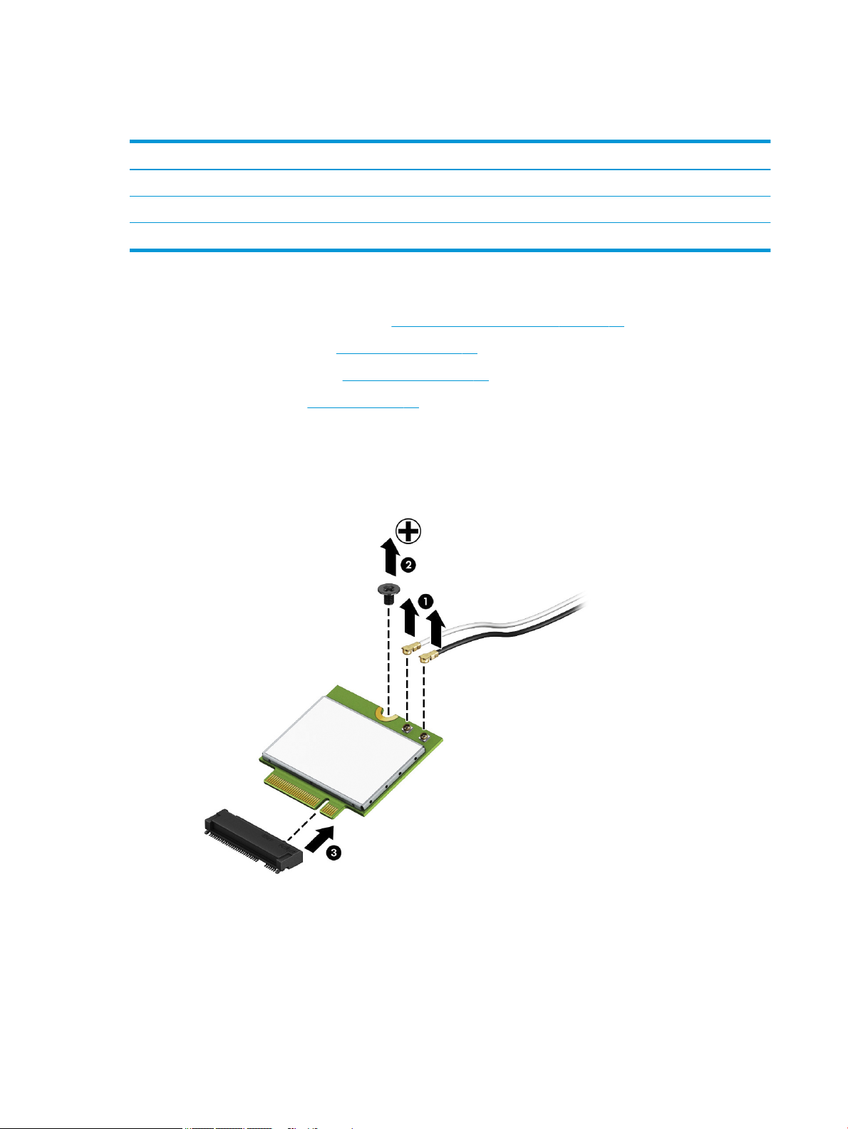
WLAN module
Table 6-7 WLAN module descriptions and part numbers
Description Spare part number
Realtek RTL8822BE 802.11ac 2 × 2 Wi-Fi + Bluetooth 4.2 Combo Adapter (MU-MIMO supported) 924813-855
Realtek RTL8821CE 802.11ac 1 × 1 Wi-Fi + Bluetooth 4.2 Combo Adapter (MU-MIMO supported) L17365-005
Realtek RTL8723DE 802.11bgn 1 × 1 Wi-Fi + Bluetooth 4.2 Combo Adapter L21480-005
Before removing the WLAN, follow these steps:
1. Prepare the computer for disassembly (Preparation for disassembly on page 33).
2. Remove the optical drive (see Optical drive on page 34).
3. Remove the bottom cover (see Bottom cover on page 38).
4. Remove the battery (see Battery on page 41).
Remove the WLAN module:
1. Disconnect the two antenna cables from the module (1).
2. Remove the Phillips M2.0 × 3.0 screw (2), and then pull the module out of the socket (3).
Reverse this procedure to install the WLAN module.
50 Chapter 6 Removal and replacement procedures for authorized service provider parts
Page 61

Hard drive connector board
Table 6-8 Hard drive connector board description and part number
Description Spare part number
Hard drive connector board L20454-001
Before removing the hard drive connector board, follow these steps:
1. Prepare the computer for disassembly (Preparation for disassembly on page 33).
2. Remove the optical drive (see Optical drive on page 34).
3. Remove the bottom cover (see Bottom cover on page 38).
4. Remove the battery (see Battery on page 41).
5. Remove the hard drive (see Hard drive on page 45).
Remove the hard drive connector:
1. Disconnect the cable from the system board ZIF connector (1).
2. Remove the Phillips M2.0 × 3.0 screw (2) that secures the board to the computer.
3. Remove the board from the computer (3).
Reverse this procedure to install the hard drive connector board.
Component replacement procedures 51
Page 62
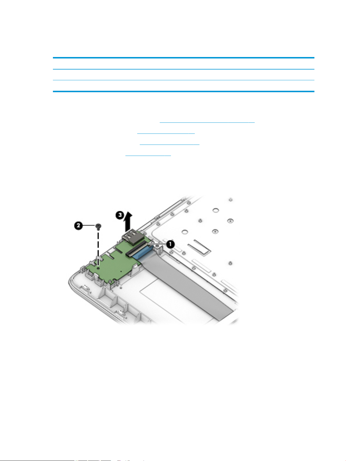
USB/card reader board
Table 6-9 USB/card reader board part descriptions and part numbers
Description Spare part number
USB/card reader board L20448-001
USB/card reader board cable L20452-001
Before removing the USB/card reader board, follow these steps:
1. Prepare the computer for disassembly (Preparation for disassembly on page 33).
2. Remove the optical drive (see Optical drive on page 34).
3. Remove the bottom cover (see Bottom cover on page 38).
4. Remove the battery (see Battery on page 41).
Remove the USB/card reader board:
1. Disconnect the cable from the ZIF connector on the USB board (1).
2. Remove the Phillips M2.0 × 3.0 screw (2), and then remove the board from the computer (3).
Reverse this procedure to replace the USB/card reader board.
52 Chapter 6 Removal and replacement procedures for authorized service provider parts
Page 63

TouchPad button board
Table 6-10 TouchPad button board part descriptions and part numbers
Description Spare part number
TouchPad button board not spared
Before removing the TouchPad button board, follow these steps:
1. Prepare the computer for disassembly (Preparation for disassembly on page 33).
2. Remove the optical drive (see Optical drive on page 34).
3. Remove the bottom cover (see Bottom cover on page 38).
4. Remove the battery (see Battery on page 41).
Remove the TouchPad button board:
1. Disconnect the system board cable from the ZIF connector on the TouchPad button board (1).
2. Disconnect the TouchPad cable from the ZIF connector on the TouchPad button board (2).
3. Remove the two Phillips M2.0 × 3.0 screws (3) that secure the board to the computer.
4. Remove the TouchPad button board from the computer (4).
Reverse this procedure to install the TouchPad button board.
Component replacement procedures 53
Page 64

TouchPad module
Table 6-11 TouchPad module part descriptions and part numbers
Description Spare part number
TouchPad module L20449-001
TouchPad module cable L20450-001
TouchPad button board cable L20451-001
Before removing the TouchPad module, follow these steps:
1. Prepare the computer for disassembly (Preparation for disassembly on page 33).
2. Remove the optical drive (see Optical drive on page 34).
3. Remove the bottom cover (see Bottom cover on page 38).
4. Remove the battery (see Battery on page 41).
To remove the TouchPad module:
1. Disconnect the TouchPad cable from the ZIF connector on the TouchPad (1) and the TouchPad button
board cable from the ZIF connector on the system board (2).
2. Peel the tape o the TouchPad (1).
3. Starting in the corner, use a plastic, non-marking tool to pry up the TouchPad module to disengage the
adhesive that secures it to the top cover (2)
54 Chapter 6 Removal and replacement procedures for authorized service provider parts
Page 65

4. Working around each edge, pry the TouchPad module loose, and then remove it from the computer (3).
NOTE: The TouchPad module may be very tight and dicult to remove.
Reverse this procedure to install the TouchPad module.
Component replacement procedures 55
Page 66

Fan
Table 6-12 Fan descriptions and part numbers
Description Spare part number
Fan for use in models with discrete graphics L20473-001
Fan for use in models with UMA graphics L20474-001
Before removing the fan, follow these steps:
1. Prepare the computer for disassembly (Preparation for disassembly on page 33).
2. Remove the optical drive (see Optical drive on page 34).
3. Remove the bottom cover (see Bottom cover on page 38).
4. Remove the battery (see Battery on page 41).
Remove the fan:
1. Disconnect the fan cable from the system board (1).
2. Remove the Phillips M2.5 × 6.0 screw (2) that secures the fan to the computer.
3. Lift the fan from the computer (3).
Reverse this procedure to install the fan.
56 Chapter 6 Removal and replacement procedures for authorized service provider parts
Page 67

Heat sink assembly
Table 6-13 Heat sink assembly descriptions and part numbers
Description Spare part number
Heat sink for use in models with AMD Ryzen processors and discrete graphics L20482-001
Heat sink for use in models with AMD A6/A9 processors and discrete graphics L20484-001
Heat sink for use in models with AMD Ryzen processors and integrated UMA graphics L20483-001
Heat sink for use in models with AMD A6/A9 processors and integrated UMA graphics L20491-001
Heat plate for use in fanless models with AMD E2-9000e processors L20494-001
Before removing the heat sink, follow these steps:
1. Prepare the computer for disassembly (Preparation for disassembly on page 33).
2. Remove the optical drive (see Optical drive on page 34).
3. Remove the bottom cover (see Bottom cover on page 38).
4. Remove the battery (see Battery on page 41).
To remove the heat sink assembly from products with integrated UMA graphics:
1. In the order indicated on the heat sink assembly, remove the four Phillips M2.0 × 3.0 screws (1) that
secure the heat sink to the computer.
2. Lift the heat sink assembly from the computer (2).
Component replacement procedures 57
Page 68

3. Thoroughly clean the thermal material from the surface of the heat sink (1) and its associated system
board component (2) each time the heat sink is removed. Replacement thermal material is included with
the heat sink and system board spare part kits.
To remove the heat sink assembly from products with discrete graphics:
1. In the order indicated on the heat sink assembly, remove the six Phillips M2.0 × 3.0 screws (1) that
secure the heat sink to the computer.
2. Lift the heat sink assembly from the computer (2).
58 Chapter 6 Removal and replacement procedures for authorized service provider parts
Page 69

3. Thoroughly clean the thermal material from the surfaces of the heat sink (1) (3) and associated system
board components (2) (4) each time the heat sink is removed. Replacement thermal material is included
with the heat sink and system board spare part kits.
To remove the heat plate from fanless models:
1. In the order indicated on the heat plate, remove the ve Phillips M2.0 × 3.0 screws (1) that secure the
heat plate to the computer.
2. Lift the heat plate from the computer (2).
Component replacement procedures 59
Page 70

3. Thoroughly clean the thermal material from the surface of the heat plate (1) and associated system
board component (2) each time the heat plate is removed. Replacement thermal material is included
with the heat plate and system board spare part kits.
Reverse this procedure to install the heat plate or heat sink assembly.
60 Chapter 6 Removal and replacement procedures for authorized service provider parts
Page 71

Display assembly
Full hinge-up displays are not spared. Displays are spared only at the subcomponent level.
Before removing the display panel, follow these steps:
1. Prepare the computer for disassembly (Preparation for disassembly on page 33).
2. Remove the optical drive (see Optical drive on page 34).
3. Remove the bottom cover (see Bottom cover on page 38).
4. Remove the battery (see Battery on page 41).
Remove the display assembly:
1. Lift the tape from the display connector on the system board (1).
2. Disconnect the cable from the connector (2).
3. Remove the cable from the clip (3).
4. Remove the four Phillips M2.5 × 6.0 screws (1) from the display hinges.
5. Remove the Phillips broad head M2.0 × 2.0 screw (2) from the right display hinge.
6. Rotate the hinges upward (3).
Component replacement procedures 61
Page 72

7. Separate the display from the computer (4).
Remove the display assembly subcomponents:
1. To remove the hinge cover, pull upward near the hinge to disengage it from the display enclosure (1),
and then remove the hinge cover from the display enclosure (2).
Hinge covers are available using the following spare part numbers:
L20423-001: Jet black
L20427-001: Sparkling black
L20424-001: Natural silver
L20425-001: Pale gold
L57159-001: Pale rose gold
L28516-001: Iridescent pale rose gold
L20430-001: Scarlet red
L20426-001: Twilight blue
L20428-001: Smoke gray
L20422-001: Snow white (full-featured models)
L21306-001: Snow white (defeatured models)
L20431-001: Maroon burgundy
L28517-001: Iridescent ceramic white
L31729-001: Ocean teal
L31730-001: Real Tree
62 Chapter 6 Removal and replacement procedures for authorized service provider parts
Page 73

L50294-001: Berry mauve; Pattern: mesh knit
L50295-001: Chalkboard gray; Pattern: mesh knit
L50297-001: Lumiere blue; Pattern: mesh knit
When replacing the hinge cover, make sure the hinges rotate downward as far as they can go. Align the
cover, and then start from above and rotate the cover downward onto the hinges. Make sure the clips
snap into place along the bottom of the display cover.
2. If it is necessary to replace the display bezel:
a. Remove the two Phillips M2.0 × 3.0 screws (1), ex the top (2) of the bezel, the inside edges of the
left and right sides (3), and then the bottom (4) of the bezel until it disengages from the display
enclosure.
Component replacement procedures 63
Page 74

b. Remove the bezel (5).
The display bezel is available using spare part number L20421-001 for standard bezels and
L32367-001 for Real Tree bezels.
3. If it is necessary to replace the camera/microphone module:
a. Detach the module (1) from the display back cover. (The module is attached with double-
sided adhesive.)
b. Disconnect the cable (2) from the camera/microphone module.
The HD camera module is available using spare part number L20447-001. The VGA camera module
is available using spare part number L20446-001.
64 Chapter 6 Removal and replacement procedures for authorized service provider parts
Page 75

4. If it is necessary to replace the display panel:
IMPORTANT: HD panels are secured to the display enclosure with screws. FHD panels are secured with
tape.
a. HD panels:
Remove the four Phillips M2.0 × 3.0 screws that secure the panel to the display enclosure.
FHD panels:
b. Pull the tape out from behind the left and right sides of the panel.
NOTE: You have to pull on the tape multiple times before it is completely removed.
Display panel stretchable adhesive tape is available using spare part number L29080-001.
c. HD and FHD panels:
Swing the top edge of the display panel forward and position it upside down next to the display
enclosure (1).
Component replacement procedures 65
Page 76
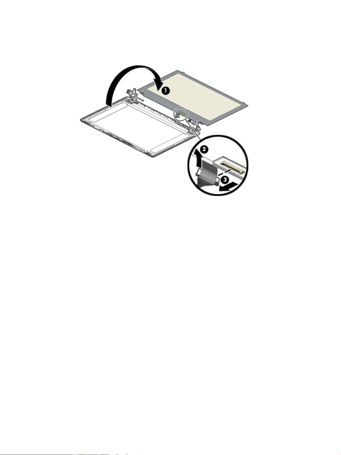
d. Release the adhesive support strip (2) that secures the display panel cable connector to the
display panel.
e. Disconnect the display panel cable (3) from the display panel.
f. Remove the display panel.
Raw display panels are available using the following spare part numbers:
L23208-001: FHD, anti glare
L23209-001: FHD, BrightView
L23210-001: HD, anti glare
L23211-001: HD, BrightView
5. If it is necessary to replace the display hinges:
a. Remove the three Phillips M2.5 × 2.5 screws (1) from each hinge.
66 Chapter 6 Removal and replacement procedures for authorized service provider parts
Page 77

b. Remove the display hinges (2).
The display hinges are available using spare part number L20420-001.
6. If it is necessary to replace the display panel cable:
a. Release the cable from the retention clips and routing channel built into the bottom edge and side
of the display enclosure (1).
b. Remove the display panel cable (2).
The display panel cable is available using the following spare part numbers:
L20443-001: HD, non-touch display
L23064-001: FHD, non-touch display
L20442-001: HD, touch display
7. If it is necessary to replace the wireless antenna cables and transceivers:
Component replacement procedures 67
Page 78

a. Remove the antennas from the top of the display enclosure (1).
b. Release the wireless antenna cables from the retention clips and routing channel built into the
sides of the display enclosure (2).
Antennas are available using the following spare part numbers:
L20445-001: Single antenna models
L23060-001: Single antenna, narrow bezel models
L20444-001: Dual antenna models
L23059-001: Dual antenna, narrow bezel models
Use the following image to determine proper cable routing in the display of the antenna cable (1) and display
cable (2).
The display rear cover is available using the following spare part numbers:
L20433-001: Jet black
68 Chapter 6 Removal and replacement procedures for authorized service provider parts
Page 79

L23061-001: Jet black (narrow bezel models)
L20437-001: Sparkling black
L20434-001: Natural silver
L23062-001: Natural silver (narrow bezel models)
L20435-001: Pale gold
L57158-001: Pale rose gold
L20440-001: Scarlet red
L20436-001: Twilight blue
L20438-001: Smoke gray
L23063-001: Smoke gray (narrow bezel models)
L20432-001: Snow white (full-featured models)
L21307-001: Snow white (defeatured models)
L20441-001: Maroon burgundy
L28509-001: Iridescent ceramic white
L28508-001: Iridescent pale rose gold
L31723-001: Ocean teal
L31724-001: Real Tree
L50301-001: Berry mauve; Pattern: mesh knit
L50302-001: Chalkboard gray; Pattern: mesh knit
L50303-001: Jet black; Pattern: mesh knit
L50304-001: Lumiere blue; Pattern: mesh knit
L50306-001: Snow white; Pattern: mesh knit; for use in defeatured models
L50307-001: Snow white; Pattern: mesh knit; for use in full-featured models
L54498-001: Chalkboard gray pattern; mesh knit
L54499-001: Jet black; Pattern: mesh knit; for use on narrow bezel models
Reverse these procedures to reassemble and install the display assembly components.
When reassembling an FHD display assembly, be sure the install the following parts into the display enclosure
from the Display Miscellaneous Kit, spare part number L23065-001 and display panel stretchable adhesive
tape, spare part number L29080-001.
(1) Four positioning corner pieces
(2) Two gaskets
(3) Display panel stretchable adhesive tape
Component replacement procedures 69
Page 80

70 Chapter 6 Removal and replacement procedures for authorized service provider parts
Page 81

System board
NOTE: All system board spare part kits include replacement thermal material.
All system boards use the following part numbers:
xxxxxx-001: Non-Windows operating systems
xxxxxx-601: Windows operating system
Table 6-14 System board descriptions and part numbers
Description Spare part number
System board for use in models with discrete graphics memory:
● AMD Athlon 300U processor and Radeon 530 graphics L53469-xx1
● AMD Ryzen 3-3200U processor and Radeon 530 graphics L46517-xx1
● AMD Ryzen 3-2200U processor and Radeon 530 graphics L20668-xx1
● AMD A9-9425 processor and Radeon 530 graphics L46513-xx1
● AMD A9-9425 processor and Radeon 520 graphics L20480-xx1
● AMD A6-9225 processor and Radeon 530 graphics L46514-xx1
● AMD A6-9225 processor and Radeon 520 graphics L20481-xx1
System board for use in models with UMA graphics memory:
● AMD Ryzen 7-3700U processor L51325-xx1
● AMD Ryzen 5-3500U processor L46515-xx1
● AMD Ryzen 3-3200U processor L46516-xx1
● AMD Ryzen 5-2500U processor L20664-xx1
● AMD Ryzen 3-2300U processor L20665-xx1
● AMD Ryzen 3-2200U processor L20666-xx1
● AMD A9-9425 processor L20477-xx1
● AMD A6-9225 processor L20478-xx1
● AMD A4-9125 processor L31720-xx1
● AMD E2-9000e processor L20479-xx1
Before removing the system board, follow these steps:
1. Prepare the computer for disassembly (Preparation for disassembly on page 33).
2. Remove the following components:
a. Optical drive (see Optical drive on page 34)
b. Bottom cover (see Bottom cover on page 38)
c. Battery (see Battery on page 41)
d. Display (see Display assembly on page 61)
Component replacement procedures 71
Page 82

When replacing the system board, be sure to remove the following components (as applicable) from
the defective system board and install them on the replacement system board:
● WLAN module (see WLAN module on page 50)
● Memory modules (see Memory module on page 43)
● Heat sink (see Heat sink assembly on page 57)
Remove the system board:
IMPORTANT: Make special note of each screw size and location during removal and replacement
1. Disconnect the following cables from the system board:
(1) Keyboard backlight cable
(2) Hard drive connector cable
(3) Speaker cable
(4) USB/card reader board cable
(5) Keyboard cable
(6) TouchPad button board cable
(7) Power connector cable
2. Remove the two Phillips M2.0 × 3.0 screws that secure the system board to the computer (1).
72 Chapter 6 Removal and replacement procedures for authorized service provider parts
Page 83

3. Lift the left side of the system board, and then remove the system board from the computer (2).
Reverse this procedure to install the system board.
Component replacement procedures 73
Page 84

Speakers
Table 6-15 Speaker Kit description and part number
Before removing the speakers, follow these steps:
1. Prepare the computer for disassembly (Preparation for disassembly on page 33).
2. Remove the optical drive (see Optical drive on page 34).
3. Remove the bottom cover (see Bottom cover on page 38).
4. Remove the battery (see Battery on page 41).
5. Remove the display (see Display assembly on page 61).
Remove the speakers:
1. Remove the speaker cable from the clips built into the computer (1).
2. Remove the speakers from the computer (2).
Description Spare part number
Speaker Kit L20453-001
Reverse this procedure to install the speakers.
74 Chapter 6 Removal and replacement procedures for authorized service provider parts
Page 85

Power connector cable (DC-in)
Table 6-16 Power connector cable description and part number
Description Spare part number
Power connector cable L20475-001
Before removing the power connector cable, follow these steps:
1. Prepare the computer for disassembly (Preparation for disassembly on page 33).
2. Remove the optical drive (see Optical drive on page 34).
3. Remove the bottom cover (see Bottom cover on page 38).
4. Remove the battery (see Battery on page 41).
5. Remove the system board (see System board on page 71).
6. Remove the display (see Display assembly on page 61).
Remove the power connector cable:
1. Remove the cable from the clips built into the computer (1).
2. Remove the power connector cable from the computer (2).
Reverse this procedure to install the power connector cable.
Component replacement procedures 75
Page 86

Top cover with keyboard
The top cover with keyboard remains after removing all other spared parts from the computer.
In this section, the rst table provides the main spare part number for the keyboards. The second table
provides the country codes.
Table 6-17 Top cover with keyboard descriptions and part numbers
Description Spare part number
Keyboard, no backlight, jet black L20387-xx1
Keyboard, no backlight, full-featured models, snow white L20388-xx1
Keyboard, no backlight, defeatured models, snow white L23066-xx1
Keyboard, no backlight, ash silver L20386-xx1
Keyboard, backlit, ash silver (available only with -001 United States, -002 India, and -DB1 Canadian
French keyboards)
Keyboard, no backlight, iridescent pale rose gold (available only with -001 United States keyboards) L28504-001
Keyboard, backlit, iridescent pale rose gold (available only with -001 United States keyboards) L28505-001
Keyboard, no backlight, iridescent ceramic white (available only with -001 United States keyboards) L28506-001
Keyboard, backlit, iridescent ceramic white (available only with -001 United States keyboards) L28507-001
Keyboard, no backlight, ocean teal (available only with -001 United States keyboards) L31735-001
Keyboard, no backlight, Real Tree (available only with -001 United States keyboards) L31736-001
Keyboard, no backlight, natural silver (available only with -002 India keyboards) L32368-002
Keyboard, backlit, ocean teal (available only with -001 United States keyboards) L32863-001
Keyboard, backlit, natural silver (available only with -002 India keyboards) L32864-002
L23074-xx1
Table 6-18 Keyboard country codes
For use in country
or region
Belgium -A41 Israel -BB1 Slovenia -BA1
Bulgaria -261 Italy -061 South Korea -AD1
Spare part
number
For use in country
or region
Spare part
number
For use in country
or region
Spare part
number
Canada -DB1 Japan -291 Spain -071
Czech Republic and
Slovakia
Denmark, Finland, and
Norway
France -051 Portugal -131 Thailand -281
Germany -041 Romania -271 Turkey -141
Greece -151 Russia -251 United Kingdom -031
Hungary -211 Saudi Arabia -171 United States -001
India -002
-FL1 Latin America -161 Switzerland -BG1
-DH1 The Netherlands -B31 Taiwan -AB1
76 Chapter 6 Removal and replacement procedures for authorized service provider parts
Page 87

7 Using Setup Utility (BIOS)
Setup Utility, or Basic Input/Output System (BIOS), controls communication between all the input and output
devices on the system (such as disk drives, display, keyboard, mouse, and printer). Setup Utility (BIOS)
includes settings for the types of devices installed, the startup sequence of the computer, and the amount of
system and extended memory.
NOTE: To start Setup Utility on convertible computers, your computer must be in notebook mode and you
must use the keyboard attached to your notebook.
Starting Setup Utility (BIOS)
CAUTION: Use extreme care when making changes in Setup Utility (BIOS). Errors can prevent the computer
from operating properly.
▲ Turn on or restart the computer and quickly press f10.
– or –
Turn on or restart the computer, quickly press esc, and then press f10 when the Start menu is displayed.
Updating Setup Utility (BIOS)
Updated versions of Setup Utility (BIOS) may be available on the HP website.
Most BIOS updates on the HP website are packaged in compressed les called SoftPaqs.
Some download packages contain a le named Readme.txt, which contains information regarding installing
and troubleshooting the le.
Determining the BIOS version
To decide whether you need to update Setup Utility (BIOS), rst determine the BIOS version on your computer.
To reveal the BIOS version information (also known as ROM date and System BIOS), use one of these options.
● HP Support Assistant
1. Type support in the taskbar search box, and then select the HP Support Assistant app.
– or –
Select the question mark icon in the taskbar.
2. Select My notebook, and then select Specications.
● Setup Utility (BIOS)
1. Start Setup Utility (BIOS) (see Starting Setup Utility (BIOS) on page 77).
2. Select Main, and then make note of the BIOS version.
3. Select Exit, select one of the options, and then follow the on-screen instructions.
● In Windows, press CTRL+Alt+S.
Starting Setup Utility (BIOS) 77
Page 88

To check for later BIOS versions, see Downloading a BIOS update on page 78.
Downloading a BIOS update
CAUTION: To reduce the risk of damage to the computer or an unsuccessful installation, download and
install a BIOS update only when the computer is connected to reliable external power using the AC adapter. Do
not download or install a BIOS update while the computer is running on battery power, docked in an optional
docking device, or connected to an optional power source. During the download and installation, follow these
instructions:
● Do not disconnect power from the computer by unplugging the power cord from the AC outlet.
● Do not shut down the computer or initiate Sleep.
● Do not insert, remove, connect, or disconnect any device, cable, or cord.
NOTE: If your computer is connected to a network, consult the network administrator before installing any
software updates, especially system BIOS updates.
1. Type support in the taskbar search box, and then select the HP Support Assistant app.
– or –
Select the question mark icon in the taskbar.
2. Select Updates, and then select Check for updates and messages.
3. Follow the on-screen instructions.
4. At the download area, follow these steps:
a. Identify the most recent BIOS update and compare it to the BIOS version currently installed on your
computer. If the update is more recent than your BIOS version, make a note of the date, name, or
other identier. You may need this information to locate the update later, after it has been
downloaded to your hard drive.
b. Follow the on-screen instructions to download your selection to the hard drive.
Make a note of the path to the location on your hard drive where the BIOS update is downloaded.
You will need to access this path when you are ready to install the update.
BIOS installation procedures vary. Follow any instructions that appear on the screen after the download is
complete. If no instructions appear, follow these steps:
1. Type file in the taskbar search box, and then select File Explorer.
2. Select your hard drive designation. The hard drive designation is typically Local Disk (C:).
3. Using the hard drive path you recorded earlier, open the folder that contains the update.
4. Double-click the le that has an .exe extension (for example, lename.exe).
The BIOS installation begins.
5. Complete the installation by following the on-screen instructions.
NOTE: After a message on the screen reports a successful installation, you can delete the downloaded le
from your hard drive.
78 Chapter 7 Using Setup Utility (BIOS)
Page 89

8 Using HP PC Hardware Diagnostics
Using HP PC Hardware Diagnostics Windows (select products only)
HP PC Hardware Diagnostics Windows is a Windows-based utility that allows you to run diagnostic tests to
determine whether the computer hardware is functioning properly. The tool runs within the Windows
operating system in order to diagnose hardware failures.
If HP PC Hardware Diagnostics Windows is not installed on your computer, rst you must download and install
it. To download HP PC Hardware Diagnostics Windows, see Downloading HP PC Hardware Diagnostics
Windows on page 79.
After HP PC Hardware Diagnostics Windows is installed, follow these steps to access it from HP Help and
Support or HP Support Assistant.
1. To access HP PC Hardware Diagnostics Windows from HP Help and Support:
a. Select the Start button, and then select HP Help and Support.
b. Right-click HP PC Hardware Diagnostics Windows, select More, and then select Run as
administrator.
– or –
To access HP PC Hardware Diagnostics Windows from HP Support Assistant:
a. Type support in the taskbar search box, and then select the HP Support Assistant app.
– or –
Select the question mark icon in the taskbar.
b. Select Troubleshooting and xes.
c. Select Diagnostics, and then select HP PC Hardware Diagnostics Windows.
2. When the tool opens, select the type of diagnostic test you want to run, and then follow the on-screen
instructions.
NOTE: If you need to stop a diagnostic test at any time, select Cancel.
When HP PC Hardware Diagnostics Windows detects a failure that requires hardware replacement, a 24-digit
Failure ID code is generated. The screen displays one of the following options:
● A Failure ID link is displayed. Select the link and follow the on-screen instructions.
● A Quick Response (QR) code is displayed. With a mobile device, scan the code and then follow the on-
screen instructions.
● Instructions for calling support are displayed. Follow those instructions.
Downloading HP PC Hardware Diagnostics Windows
● The HP PC Hardware Diagnostics Windows download instructions are provided in English only.
● You must use a Windows computer to download this tool because only .exe les are provided.
Using HP PC Hardware Diagnostics Windows (select products only) 79
Page 90

Downloading the latest HP PC Hardware Diagnostics Windows version
To download HP PC Hardware Diagnostics Windows, follow these steps:
1. Go to http://www.hp.com/go/techcenter/pcdiags. The HP PC Diagnostics home page is displayed.
2. Select Download HP Diagnostics Windows, and then select a location on your computer or a USB ash
drive.
The tool is downloaded to the selected location.
Downloading HP Hardware Diagnostics Windows by product name or number (select products only)
NOTE: For some products, it may be necessary to download the software to a USB ash drive by using the
product name or number.
To download HP PC Hardware Diagnostics Windows by product name or number, follow these steps:
1. Go to http://www.hp.com/support.
2. Select Get software and drivers, select your type of product, and then enter the product name or
number in the search box that is displayed.
3. In the Diagnostics section, select Download, and then follow the on-screen instructions to select the
specic Windows diagnostics version to be downloaded to your computer or USB ash drive.
The tool is downloaded to the selected location.
Installing HP PC Hardware Diagnostics Windows
To install HP PC Hardware Diagnostics Windows, follow these steps:
▲ Navigate to the folder on your computer or the USB ash drive where the .exe le was downloaded,
double-click the .exe le, and then follow the on-screen instructions.
Using HP PC Hardware Diagnostics UEFI
NOTE: For Windows 10 S computers, you must use a Windows computer and a USB ash drive to download
and create the HP UEFI support environment because only .exe les are provided. For more information, see
Downloading HP PC Hardware Diagnostics UEFI to a USB ash drive on page 81.
HP PC Hardware Diagnostics UEFI (Unied Extensible Firmware Interface) allows you to run diagnostic tests to
determine whether the computer hardware is functioning properly. The tool runs outside the operating
system so that it can isolate hardware failures from issues that are caused by the operating system or other
software components.
If your PC will not boot into Windows, you can use HP PC Hardware Diagnostics UEFI to diagnose hardware
issues.
When HP PC Hardware Diagnostics Windows detects a failure that requires hardware replacement, a 24-digit
Failure ID code is generated. For assistance in solving the problem:
▲ Select Get Support, and then use a mobile device to scan the QR code that displays on the next screen.
The HP Customer Support - Service Center page displays, with your Failure ID and product number
automatically lled in. Follow the on-screen instructions.
– or –
Contact support, and provide the Failure ID code.
80 Chapter 8 Using HP PC Hardware Diagnostics
Page 91

NOTE: To start diagnostics on a convertible computer, your computer must be in notebook mode, and you
must use the attached keyboard.
NOTE: If you need to stop a diagnostic test, press esc.
Starting HP PC Hardware Diagnostics UEFI
To start HP PC Hardware Diagnostics UEFI, follow these steps:
1. Turn on or restart the computer, and quickly press esc.
2. Press f2.
The BIOS searches three places for the diagnostic tools, in the following order:
a. Connected USB ash drive
NOTE: To download the HP PC Hardware Diagnostics UEFI tool to a USB ash drive, see
Downloading the latest HP PC Hardware Diagnostics UEFI version on page 81.
b. Hard drive
c. BIOS
3. When the diagnostic tool opens, select a language, select the type of diagnostic test you want to run,
and then follow the on-screen instructions.
Downloading HP PC Hardware Diagnostics UEFI to a USB ash drive
Downloading HP PC Hardware Diagnostics UEFI to a USB ash drive can be useful in the following situations:
● HP PC Hardware Diagnostics UEFI is not included in the preinstall image.
● HP PC Hardware Diagnostics UEFI is not included in the HP Tool partition.
● The hard drive is damaged.
NOTE: The HP PC Hardware Diagnostics UEFI download instructions are provided in English only, and you
must use a Windows computer to download and create the HP UEFI support environment because only .exe
les are provided.
Downloading the latest HP PC Hardware Diagnostics UEFI version
To download the latest HP PC Hardware Diagnostics UEFI version to a USB ash drive:
1. Go to http://www.hp.com/go/techcenter/pcdiags. The HP PC Diagnostics home page is displayed.
2. Select Download HP Diagnostics UEFI, and then select Run.
Downloading HP PC Hardware Diagnostics UEFI by product name or number (select products only)
NOTE: For some products, it may be necessary to download the software to a USB ash drive by using the
product name or number.
To download HP PC Hardware Diagnostics UEFI by product name or number (select products only) to a USB
ash drive:
Using HP PC Hardware Diagnostics UEFI 81
Page 92

1. Go to http://www.hp.com/support.
2. Enter the product name or number, select your computer, and then select your operating system.
3. In the Diagnostics section, follow the on-screen instructions to select and download the specic UEFI
Diagnostics version for your computer.
Using Remote HP PC Hardware Diagnostics UEFI settings (select products only)
Remote HP PC Hardware Diagnostics UEFI is a rmware (BIOS) feature that downloads HP PC Hardware
Diagnostics UEFI to your computer. It can then execute the diagnostics on your computer, and it may upload
results to a precongured server. For more information about Remote HP PC Hardware Diagnostics UEFI, go to
http://www.hp.com/go/techcenter/pcdiags, and then select Find out more.
Downloading Remote HP PC Hardware Diagnostics UEFI
NOTE: HP Remote PC Hardware Diagnostics UEFI is also available as a Softpaq that can be downloaded to a
server.
Downloading the latest Remote HP PC Hardware Diagnostics UEFI version
To download the latest Remote HP PC Hardware Diagnostics UEFI version, follow these steps:
1. Go to http://www.hp.com/go/techcenter/pcdiags. The HP PC Diagnostics home page is displayed.
2. Select Download Remote Diagnostics, and then select Run.
Downloading Remote HP PC Hardware Diagnostics UEFI by product name or number
NOTE: For some products, it may be necessary to download the software by using the product name or
number.
To download HP Remote PC Hardware Diagnostics UEFI by product name or number, follow these steps:
1. Go to http://www.hp.com/support.
2. Select Get software and drivers, select your type of product, enter the product name or number in the
search box that is displayed, select your computer, and then select your operating system.
3. In the Diagnostics section, follow the on-screen instructions to select and download the Remote UEFI
version for the product.
Customizing Remote HP PC Hardware Diagnostics UEFI settings
Using the Remote HP PC Hardware Diagnostics setting in Computer Setup (BIOS), you can perform the
following customizations:
● Set a schedule for running diagnostics unattended. You can also start diagnostics immediately in
interactive mode by selecting Execute Remote HP PC Hardware Diagnostics.
● Set the location for downloading the diagnostic tools. This feature provides access to the tools from the
HP website or from a server that has been precongured for use. Your computer does not require the
traditional local storage (such as a disk drive or USB ash drive) to run remote diagnostics.
82 Chapter 8 Using HP PC Hardware Diagnostics
Page 93

● Set a location for storing the test results. You can also set the user name and password settings used for
uploads.
● Display status information about the diagnostics run previously.
To customize Remote HP PC Hardware Diagnostics UEFI settings, follow these steps:
1. Turn on or restart the computer, and when the HP logo appears, press f10 to enter Computer Setup.
2. Select Advanced, and then select Settings.
3. Make your customization selections.
4. Select Main, and then Save Changes and Exit to save your settings.
Your changes take eect when the computer restarts.
Using Remote HP PC Hardware Diagnostics UEFI settings (select products only) 83
Page 94

9 Backing up, restoring, and recovering
This chapter provides information about the following processes, which are standard procedure for most
products:
● Backing up your personal information—You can use Windows tools to back up your personal
information (see Using Windows tools on page 84).
● Creating a restore point—You can use Windows tools to create a restore point (see Using Windows
tools on page 84).
● Creating recovery media (select products only)—You can use the HP Cloud Recovery Download Tool
(select products only) to create recovery media (see Using the HP Cloud Recovery Download Tool to
create recovery media (select products only) on page 84).
● Restoring and recovery—Windows oers several options for restoring from backup, refreshing the
computer, and resetting the computer to its original state (see Using Windows tools on page 84).
IMPORTANT: If you will be performing recovery procedures on a tablet, the tablet battery must be at least
70% charged before you start the recovery process.
IMPORTANT: For a tablet with a detachable keyboard, connect the tablet to the keyboard base before
beginning any recovery process.
Backing up information and creating recovery media
Using Windows tools
IMPORTANT: Windows is the only option that allows you to back up your personal information. Schedule
regular backups to avoid information loss.
You can use Windows tools to back up personal information and create system restore points and recovery
media.
NOTE: If computer storage is 32 GB or less, Microsoft System Restore is disabled by default.
For more information and steps, see the Get Help app.
1. Select the Start button, and then select the Get Help app.
2. Enter the task you want to perform.
NOTE: You must be connected to the Internet to access the Get Help app.
Using the HP Cloud Recovery Download Tool to create recovery media (select products only)
You can use the HP Cloud Recovery Download Tool to create HP Recovery media on a bootable USB ash drive.
To download the tool:
▲ Go to the Microsoft Store and search for HP Cloud Recovery.
For details, go to http://www.hp.com/support, search for HP Cloud Recovery, and then select "HP PCs – Using
the Cloud Recovery Tool (Windows 10, 7)."
84 Chapter 9 Backing up, restoring, and recovering
Page 95

NOTE: If you cannot create recovery media yourself, contact support to obtain recovery discs. Go to
http://www.hp.com/support, select your country or region, and then follow the on-screen instructions.
Restoring and recovery
Restoring, resetting, and refreshing using Windows tools
Windows oers several options for restoring, resetting, and refreshing the computer. For details, see Using
Windows tools on page 84.
Recovering using HP Recovery media
HP Recovery media is used to recover the original operating system and software programs that were
installed at the factory. On select products, it can be created on a bootable USB ash drive using the HP Cloud
Recovery Download Tool. For details, see Using the HP Cloud Recovery Download Tool to create recovery
media (select products only) on page 84.
NOTE: If you cannot create recovery media yourself, contact support to obtain recovery discs. Go to
http://www.hp.com/support, select your country or region, and then follow the on-screen instructions.
To recover your system:
▲ Insert the HP Recovery media, and then restart the computer.
Changing the computer boot order
If your computer does not restart using the HP Recovery media, you can change the computer boot order. This
is the order of devices listed in BIOS where the computer looks for startup information. You can change the
selection to an optical drive or a USB ash drive, depending on the location of your HP Recovery media.
To change the boot order:
IMPORTANT: For a tablet with a detachable keyboard, connect the tablet to the keyboard base before
beginning these steps.
1. Insert the HP Recovery media.
2. Access the system Startup menu.
For computers or tablets with keyboards attached:
▲ Turn on or restart the computer or tablet, quickly press esc, and then press f9 for boot options.
For tablets without keyboards:
▲ Turn on or restart the tablet, quickly hold down the volume up button, and then select f9.
‒ or –
Turn on or restart the tablet, quickly hold down the volume down button, and then select f9.
3. Select the optical drive or USB ash drive from which you want to boot, and then follow the on-screen
instructions.
Restoring and recovery 85
Page 96

10 Specications
Computer specications
Table 10-1 Computer specications
Metric U.S.
Dimensions
Length 246.0 mm 10.72 in
Width 376.0 mm 16.33 in
Height 22.5 mm 0.97 in
Weight (lowest conguration)
SSD, Ryzen processors, UMA graphics 1829.5 g 4.03 lbs
SSD, A9/A6/A4 processors, UMA graphics 1771.5 g 3.91 lbs
SSD, Ryzen/A9/A6/A4 processors, discrete graphics 1855.5 g 4.09 lbs
HDD and ODD, Ryzen processors, UMA graphics 2062.7 g 4.55 lbs
HDD and ODD, A9/A6/A4 processors, UMA graphics 2004.7 g 4.42 lbs
HDD and ODD, Ryzen/A9/A6/A4 processors, discrete graphics 2088.7 g 4.60 lbs
Input power
Operating voltage 19.0 V dc @ 4.74 A – 90 W or 18.5 V dc @ 3.5 A - 65 W or 45 W
Operating current 4.74 A or 3.5 A
Temperature
Operating (not writing to optical disc) 0°C to 35°C 32°F to 95°F
Operating (writing to optical disc) 5°C to 35°C 41°F to 95°F
Nonoperating -20°C to 60°C -4°F to 140°F
Relative humidity
Operating 10% to 90%
Nonoperating 5% to 95%
NOTE: Applicable product safety standards specify thermal limits for plastic surfaces. The computer operates well within this range
of temperatures.
86 Chapter 10 Specications
Page 97

39.6-cm (15.6-in) display specications
Table 10-2 Display specications
Metric U.S.
Active diagonal size 39.6-cm 15.6-in
Resolution FHD: 1920 × 1080
HD: 1366 × 768
Surface treatment Anti-glare
BrightView
Brightness 220 nits
200 nits (BrightView, HD, Touch-on Panel)
Viewing angle SVA
UWVA (FHD, anti glare panel)
Backlight WLED
Aspect ratio 16:10 ultra wide
Display panel interface eDP
Width Slim-at, 3.2 mm
M.2 SATA solid-state drive specications
Table
10-3 Solid-state drive specications
128-GB* 256-GB*
Height 1.35 mm 1.35 mm
Weight < 10 g < 10 g
Form factor M.2 2280-D2-B-M M.2 2280-D2-B-M
Transfer rate up to 540 MB/sec up to 540 MB/sec
Interface type SATA-3 SATA-3
Ready time, maximum (to not busy) 1.0 ms < 1.0 ms
Access times, logical 0.1 ms 0.1 ms
Total logical sectors 234,441,648 468,883,296
Operating temperature 0°C to 70°C (32°F to 158°F)
*1 GB = 1 billion bytes when referring to hard drive storage capacity. Actual accessible capacity is less. Actual drive specications may
dier slightly.
NOTE: Certain restrictions and exclusions apply. Contact technical support for details.
39.6-cm (15.6-in) display specications 87
Page 98

M.2 PCIe solid-state drive specications
Table 10-4 Solid-state drive specications
256-GB*
Dimensions
Height 1 mm
Length 50.8 mm
Width 28.9 mm
Weight < 10 g
Interface type ATA-7
Transfer rate
Sequential Read
Random Read
Sequential Write
Random Write
Ready time, Maximum (to not busy) 1.0 s
Access times
Logical 0.1 ms
Total logical sectors 500,118,192
Operating temperature
Operating
Non-operating
*1 GB = 1 billion bytes when referring to hard drive storage capacity. Actual accessible capacity is less.
NOTE: Certain restrictions and exclusions apply. Contact technical support for details.
Up to 2150 MB/s
Up to 300,000 IOPs
Up to 1260 MB/s
Up to 100,000 IOPs
0° to 70°C (32°F to 158°F)
-40° to 80°C (-40°F to 176°F)
88 Chapter 10 Specications
Page 99

Hard drive specications
Table 10-5 Hard drive specications
2-TB* 1-TB* 500-GB*
Dimensions
Height 7.2 mm or 9.5 mm 7.2 mm or 9.5 mm 7.0 mm
Length 100.4 mm 100.4 mm 100.6 mm
Width 69.9 mm 69.9 mm 70.1 mm
Weight 130.0 g 107.0 g 92.0 g
Interface type SATA SATA SATA
Transfer rate
Synchronous (maximum) 300 MB/sec 300 MB/sec 300 MB/sec
Security ATA security ATA security ATA security
Seek times (typical read, including setting)
Single track 2.0 ms 2.0 ms 3 ms
Average (read/write) 12 ms 12 ms 13 ms
Maximum 22 ms 22 ms 24 ms
Logical blocks 3,907,029,168 1,953,525,168 1,048,576,000
Disk rotational speed 5400 rpm 5400 rpm 5400 rpm
Operating temperature 0°C to 60°C (32°F to 140°F)
*1 GB = 1 billion bytes when referring to hard drive storage capacity. Actual accessible capacity is less.
NOTE: Certain restrictions and exclusions apply. Contact technical support for details.
Hard drive specications 89
Page 100

11 Power cord set requirements
The wide-range input feature of the computer permits it to operate from any line voltage from 100 to 120
volts AC, or from 220 to 240 volts AC.
The 3-conductor power cord set included with the computer meets the requirements for use in the country or
region where the equipment is purchased.
Power cord sets for use in other countries and regions must meet the requirements of the country or region
where the computer is used.
Requirements for all countries
The following requirements are applicable to all countries and regions:
● The length of the power cord set must be at least 1.0 m (3.3 ft) and no more than 2.0 m (6.5 ft).
● All power cord sets must be approved by an acceptable accredited agency responsible for evaluation in
the country or region where the power cord set will be used.
● The power cord sets must have a minimum current capacity of 10 amps and a nominal voltage rating of
125 or 250 V AC, as required by the power system of each country or region.
● The appliance coupler must meet the mechanical conguration of an EN 60 320/IEC 320 Standard Sheet
C13 connector for mating with the appliance inlet on the back of the computer.
Requirements for specic countries and regions
Table
11-1 Power cord requirements for specic countries and regions
Country/region Accredited agency Applicable note number
Australia EANSW 1
Austria OVE 1
Belgium CEBC 1
Canada CSA 2
Denmark DEMKO 1
Finland FIMKO 1
France UTE 1
Germany VDE 1
Italy IMQ 1
Japan METI 3
The Netherlands KEMA 1
Norway NEMKO 1
The People's Republic of China COC 5
90 Chapter 11 Power cord set requirements
 Loading...