

Page 1
OSClllOSCOPE
OPERATING
AND
SERVICING MANUAL
Page 2
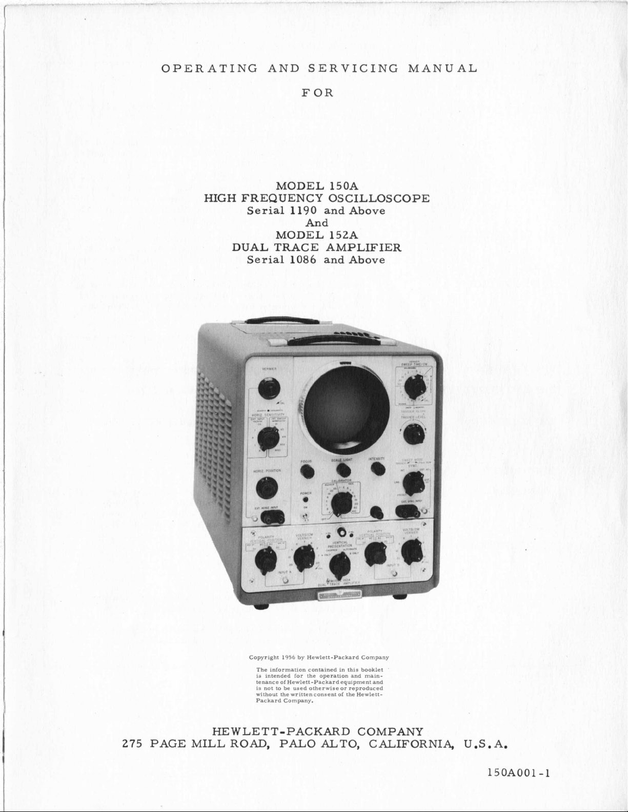
OPERATING AND SERVICING MANUAL
FOR
MODEL 150A
HIGH
FREQUENCY OSCILLOSCOPE
Serial
1190
and
Above
And
MODEL 152A
DUAL TRACE AMPLIFIER
Serial
1086
and
Above
,
275
PAGE MILL ROAD,
Copyright
HE
WLET T-PACKARD COMPANY
1956
by Hewlett-Packard Company
The information contained in this booklet
i3 intended for the operation and maintenance of Hewlett-Packard equipment and
is not to be used otherwise or reproduced
without the writtenconsent
Packard Company.
PAL0
of
the Hewlett-
ALTO,
CALIFORNIA, U.S.A.
'
15OAOO1-1
Page 3
INTERNAL SWEEP:
MAGNIFICAT ION:
SYNCHRONIZATION:
SYNC CONTROL:
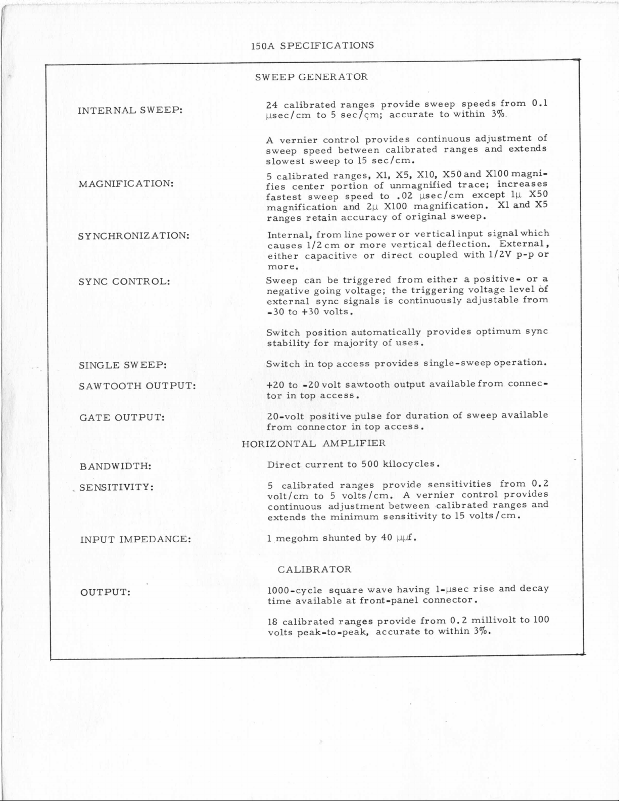
150A SPECIFICATIONS
SWEEP GENERATOR
24
calibrated ranges provide sweep speeds from 0.1
psec/cm to 5 sec/cm; accurate to within
A vernier control provides continuous adjustment of
sweep speed between calibrated ranges and extends
slowest sweep to 15 sec/cm.
5 calibrated ranges, X1, X5, X10, X50 and XlOO magni-
fies center portion of unmagnified trace; increases
fastest sweep speed to
magnification and
ranges retain accuracy of original sweep.
Internal, from line power or vertical input signal which
causes 1/2 cm or more vertical deflection. External,
either capacitive or direct coupled with 1/2V p-p or
more.
Sweep can be triggered from either
negative going voltage; the triggering voltage level of
external sync signals
-30
to
+30
volts.
Switch position automatically provides optimum sync
stability for majority of uses.
2p
.02
XlOO
is
psec/cm except lp X50
magnification. X1 and X5
continuously adjustable from
39%.
a
positive- or
a
SINGLE SWEEP:
SAWTOOTH OUTPUT:
GATE OUTPUT:
BAND WIDTH:
.
SENSITIVITY:
INPUT IMPEDANCE:
OUTPUT:
Switch in top access provides single-sweep operation.
+20
to
-20
volt sawtooth output available from connec-
tor in top access.
20-volt positive pulse for duration of sweep available
from connector in top access.
HORIZONTAL AMPLIFIER
Direct current to 500 kilocycles.
5 calibrated ranges provide sensitivities from
volt/cm to 5 volts/cm. A vernier control provides
continuous adjustment between calibrated ranges and
extends the minimum sensitivity to 15 volts/cm.
1 megohm shunted by
CALIBRATOR
1000-cycle square wave having 1-psec rise and decay
time available
18 calibrated ranges provide from
volts peak-to-peak, accurate to within
at
40
pfl.
front-panel connector
0.2
.
millivolt to 100
370.
0.2
Page 4
I
I
,
I
I
,
!
t
I
!
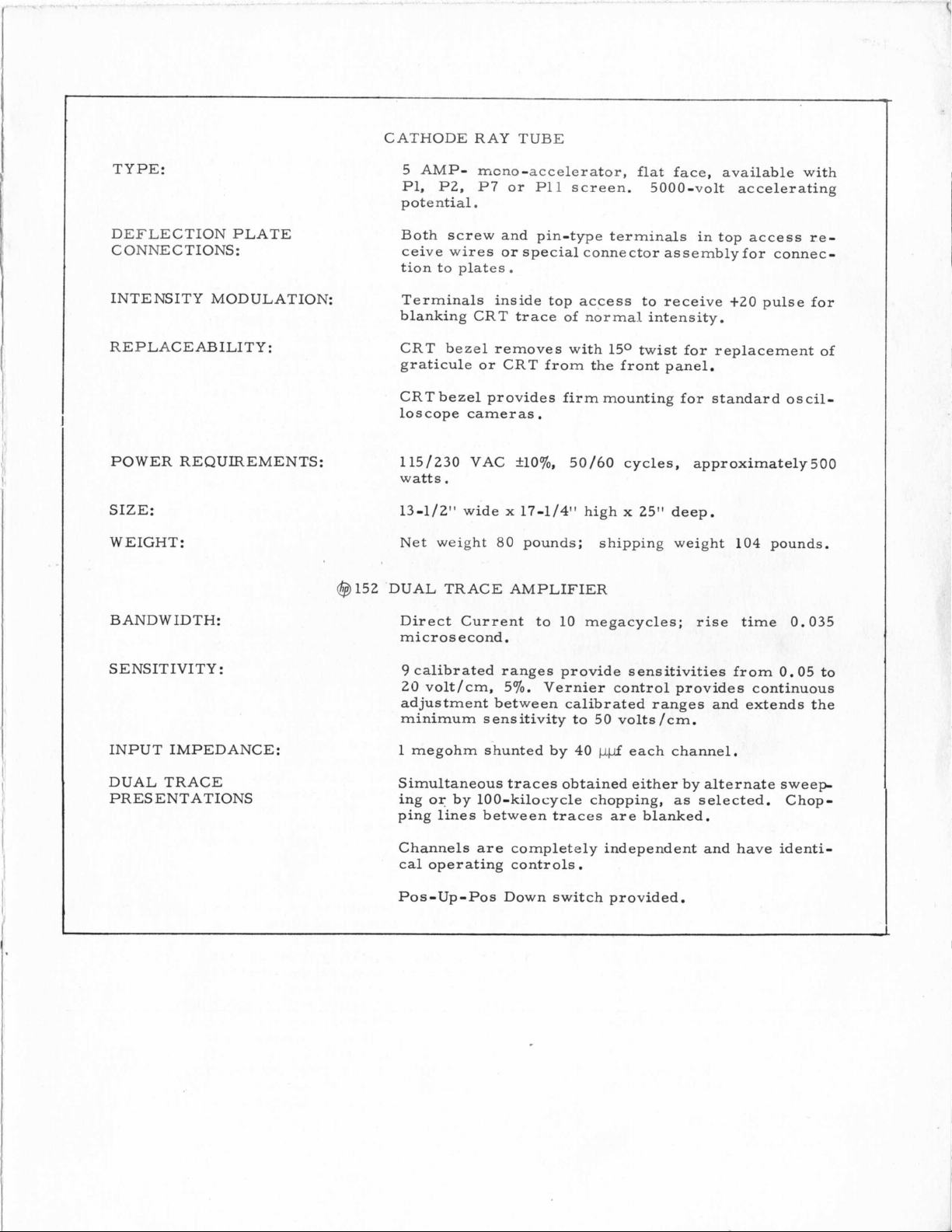
TYPE:
CATHODE RAY TUBE
5 AMP-
P1,
potential
rr-cno-accelerator,
P2,
P7
.
or P11 screen. 5000-volt accelerating
flat face, available with
\
I
i
I
1
I
DEFLECTION PLATE
CONNECTIONS:
INTENSITY MODULATION:
REPLACEABILITY:
POWER REQUIREMENTS:
SIZE:
WEIGHT:
BANDWIDTH:
SENSITIVITY:
Both screw and pin-type terminals in top access re-
or
ceive wires
tion to plates.
Terminals inside top access to receive +20 pulse for
blanking CRT trace of normal intensity.
CRT bezel removes with
graticule or CRT from the front panel.
CRT bezel provides firm mounting for standard oscilloscope cameras
115/230 VAC
watts.
13-1/2" wide
Net weight
@l52 DUAL TRACE AMPLIFIER
Direct Current to
microsecond.
9
calibrated ranges provide sensitivities from
20 volt/cm, 57'0. Vernier control provides continuous
adjustment between calibrated ranges and extends the
minimum sensitivity to 50 volts /cm.
special connector assembly for connec-
.
+lo%,
x
17-1/411
80
pounds; shipping weight
50/60
high x 25" deep.
10
megacycles; rise time 0.035
150
twist for replacement of
cycles, approximately500
104
pounds.
0.05
to
INPUT IMPEDANCE:
I
I
,
1
I
I
I
i
DUAL TRACE
PRESENTATIONS
1'
i
!
I
i
i
I
I
i
i
I
1
megohm shunted by
Simultaneous traces obtained either by alternate sweep
or
ing
ping lines between traces are blanked.
Channels are completely independent and have identical operating controls
Pos-Up-Pos Down switch provided.
by 100-kilocycle chopping,
40
.
ppf
each channel.
as
selected. Chop-
Page 5
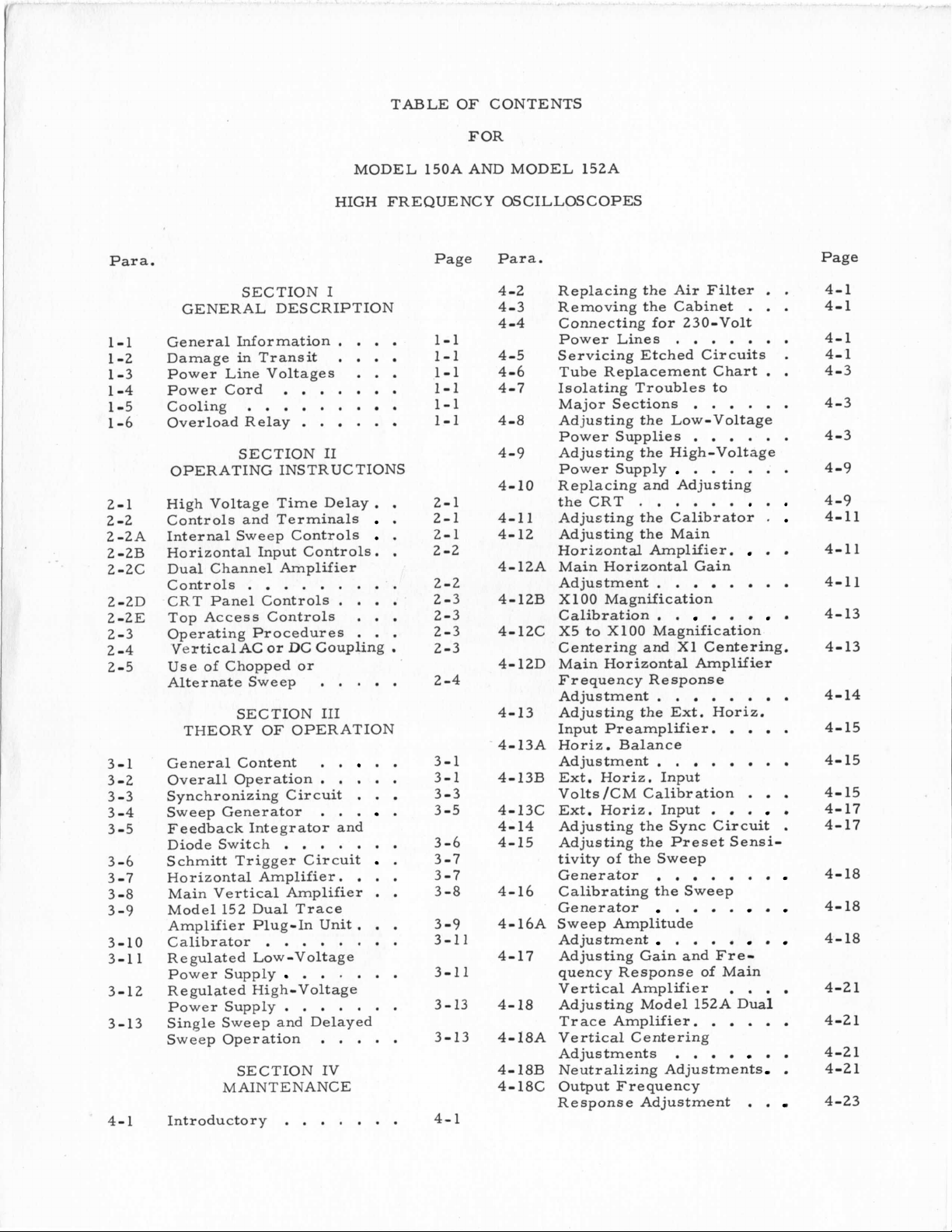
TABLE OF CONTENTS
FOR
MODEL 150A AND MODEL 152A
HIGH FREQUENCY OSCILLOSCOPES
Par
1-1
1-2
1-3
1 -4
1-5
1-6
2-1
2 -2
2-2A
2-2B
2-2c
2-2D
2-2E
2-3
2 -4
2-5
3-1
3-2
3 -3
3 -4
3-5
3-6
3-7
3-8
-9
3
3-10
3-1 1
3-12
3-13
4-1
a
.
SECTION
GENERAL DESCRIPTION
General Information.
Damage
Power Line Voltages
Power Cord
Cooling
Overload Relay
OPERATING INSTRUCTIONS
High Voltage Time Delay
Controls and Terminals
Internal Sweep Controls
Horizontal Input Controls.
Dual Channel Amplifier
Controls
CRT Panel Controls
Top Access Controls
Operating Procedures
'Vertical
Use of Chopped or
Alternate Sweep
THEORY
General Content
Overall Operation
Synchronizing Circuit
Sweep Generator
Feedback Integrator and
Diode Switch
Schmitt Trigger Circuit
Horizontal Amplifier.
Main Vertical Amplifier
Model 152 Dual Trace
Amplifier Plug-In Unit
Calibrator
Regulated Low-Voltage
Power Supply
Re gulate d High-Volt age
Power Supply
Single Sweep and Delayed
Sweep Operation
Introductory
in
Transit
.
. . . . . .
.
.
. . . .
. .
SECTION I1
. . .
AC
.
. .
or DC Coupling
. . . . .
SECTION
OF
111
OPERATION
. . .
. .
. .
. .
. .
. . . . . . . .
.
.
. . . . . . .
. . .
SECTION IV
MAINTENANCE
. . . . . . .
I
. .
. . .
. .
.
.
. .
.
. .
.
. . .
. .
. . .
.
. . .
. . .
. .
.
.
.
.
.
.
.
.
. .
.
.
.
.
.
.
.
.
.
.
.
.
.
.
.
.
.
. .
.
.
Page
1-1
1-1
1-1
1-1
1-1
1-1
2-1
2-1
2-1
2 -2
2-2
2-3
2-3
2-3
2-3
2 -4
3-1
3-1
3-3
3-5
3-6
3-7
3-7
3-8
-9
3
3-1
3-1 1
3-13
3-13
4-1
Para.
4-2
4-3
-4
4
4-5
4-6
4-7
4-8
4-9
4-10
4-11
4-12
4-12A
4-12B XlOO Magnification
4-12C X5 to XlOO Magnification
4- 12D Main Horizontal Amplifier
4-13 Adjusting the Ext. Horiz.
4- 13A Horiz . Balance
4-13B Ext. Horiz. Input
4-13C Ext. Horiz. Input
4-14 Adjusting the Sync Circuit
4-15 Adjusting the Preset Sensi-
4-16 Calibrating the Sweep
4- 16A Sweep Amplitude
1
4-17 Adjusting Gain and Fre-
4-18 Adjusting Model 152A
4-18A Vertical Centering
4- 18B Neutralizing Adjustments
4-18C Output Frequency
Replacing the Air Filter
Removing the Cabinet
Connecting for 230-Volt
Power Lines
Servicing Etched Circuits
Tube Replacement Chart
Isolating Troubles to
Major Sections
Adjusting the Low-Voltage
Power Supplies
Adjusting the High-Voltage
Power Supply
Replacing and Adjusting
theCRT
Adjusting the Calibrator
Adjusting the Main
Horizontal Amplifier.
Main Horizontal Gain
Adjustment
Calibration
Centering and X1 Centering.
Frequency Response
Adjustment
Input Preamplifier.
Adjustment.
Volts/CM Calibration
tivity of the Sweep
Generator
Generator
Adjustment
quency Response
Vertical Amplifier
Trace Amplifier.
Adjustments
Response Adjustment
. . . .
. . . . .
.
. . . . . .
.
. . . . . .
.
.
. . . . .
.
.
.
.
.
.
. . .
.
.
.
.
. .
. . .
.
.
.
. .
. . .
. . .
.
. . . .
. . . .
. . .
. .
.
.
. .
.
. . .
.
.
of
Main
. . .
Dual
. . . .
. .
.
. .
.
.
.
.
. .
.
.
.
.
.
.
.
.
.
.
.
.
.
.
.
.
.
.
Page
1
44-1
4-1
4- 1
4-3
4-3
4-3
4-9
4-9
4-11
4-11
4-11
4-13
4-13
4-14
4-15
4-15
4- 15
4-17
4-17
4-18
4-
18
4-18
4-21
4-2 1
4-21
4-21
4-23
Page 6
1-1
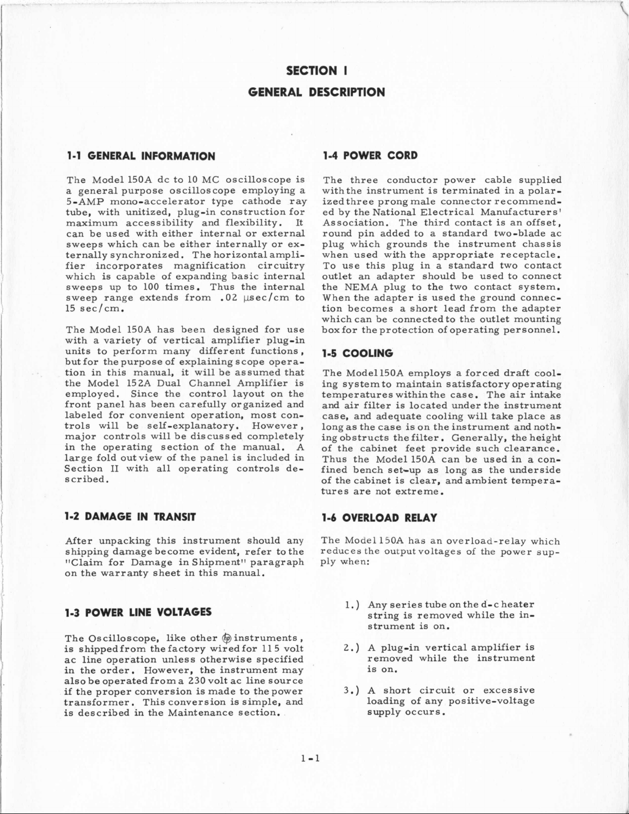
GENERAL INFORMATION
SECTION
I
GENERAL DESCRIPTION
1-4
POWER CORD
The Model 150A dc to 10 MC oscilloscope
a
general purpose oscilloscope employing
5-AMP mono-accelerator type cathode ray
tube, with unitized, plug-in construction for
maximum accessibility and flexibility. It
can be used with either internal or external
sweeps which can be either internally or externally synchronized. The horizontal amplifier incorporates magnification circuitry
is
which
sweeps up
sweep range extends from .02 bsec/cm to
15 sec/cm.
The Model 150A has been designed for use
with
units to perform many different functions
but for the purpose of explaining scope operation in this manual,
the Model 152A Dual Channel Amplifier
employed, Since the control layout on the
front panel has been carefully organized and
labeled for convenient operation, most controls will be self-explanatory. However
major controls will be discussed completely
in the operating section of the manual. A
large fold outview of the panel
Section I1 with
s
cr ibed
capable of expanding basic internal
to
100 times. Thus the internal
a
variety of vertical amplifier plug-in
it
will be assumed that
is
included in
all
operating controls de-
.
is
is
The three conductor power cable supplied
withthe instrument
a
ized three prong male connector recommend-
ed by the National Electrical Manufacturers'
Association. The third contact
round pin added to
plug which grounds the instrument chassis
when used with the appropriate receptacle.
To use this plug in
outlet an adapter should be used to connect
the NEMA plug to the two contact system.
When the adapter
tion becomes
which can be connected to the outlet mounting
box for the protection of operating personnel.
,
1-5
COOLING
The Modell5OA employs a forced draft cooling system to maintain satisfactory operating
temperatures within the case. The
and
air
filter
case, and adequate cooling will take place
,
long
as
the case
ing obstructs the filter. Generally, the height
of the cabinet feet provide such clearance.
Thus the Model150A can be used in
fined bench set-up
of the cabinet
tures are not extreme.
is
is
is
terminated in a polar-
is
a
standard two-blade ac
a
standard two contact
is
used the ground connec-
a
short lead from the adapter
located under the instrument
is
on the instrument and noth-
as
long
as
the underside
clear, and ambient tempera-
an offset,
air
intake
as
a
con-
1-2
DAMAGE IN TRANSIT
After unpacking this instrument should any The Model
shipping damage become evident, refer to the reduces the output voltages
1lClaim for Damage in Shipment" paragraph ply when:
on the warranty sheet in this manual.
1-3
POWER LINE VOLTAGES
The Oscilloscope, like other @ instruments,
is
shippedfrom thefactory wiredfor 115 volt
ac line operation unless otherwise specified
in the order. However, the instrument may
also be operated from a 230 volt ac line source
if
the proper conversion
transformer. This conversion
is
described in the Maintenance section.
is
made to the power
is
simple, and
1-6
OVERLOAD RELAY
150A
1.
)
Any series tube on the d'-c heater
string
strument
2.)
A plug-in vertical amplifier
removed while the instrument
is
on.
3.)
A short circuit or excessive
loading of any positive-voltage
supply occurs.
has an overload-relay which
is
removed while the in-
is
on.
1-1
of
the power
SUP-
is
Page 7
Page 8
i
SECTION
OPERATING INSTRUCTIONS
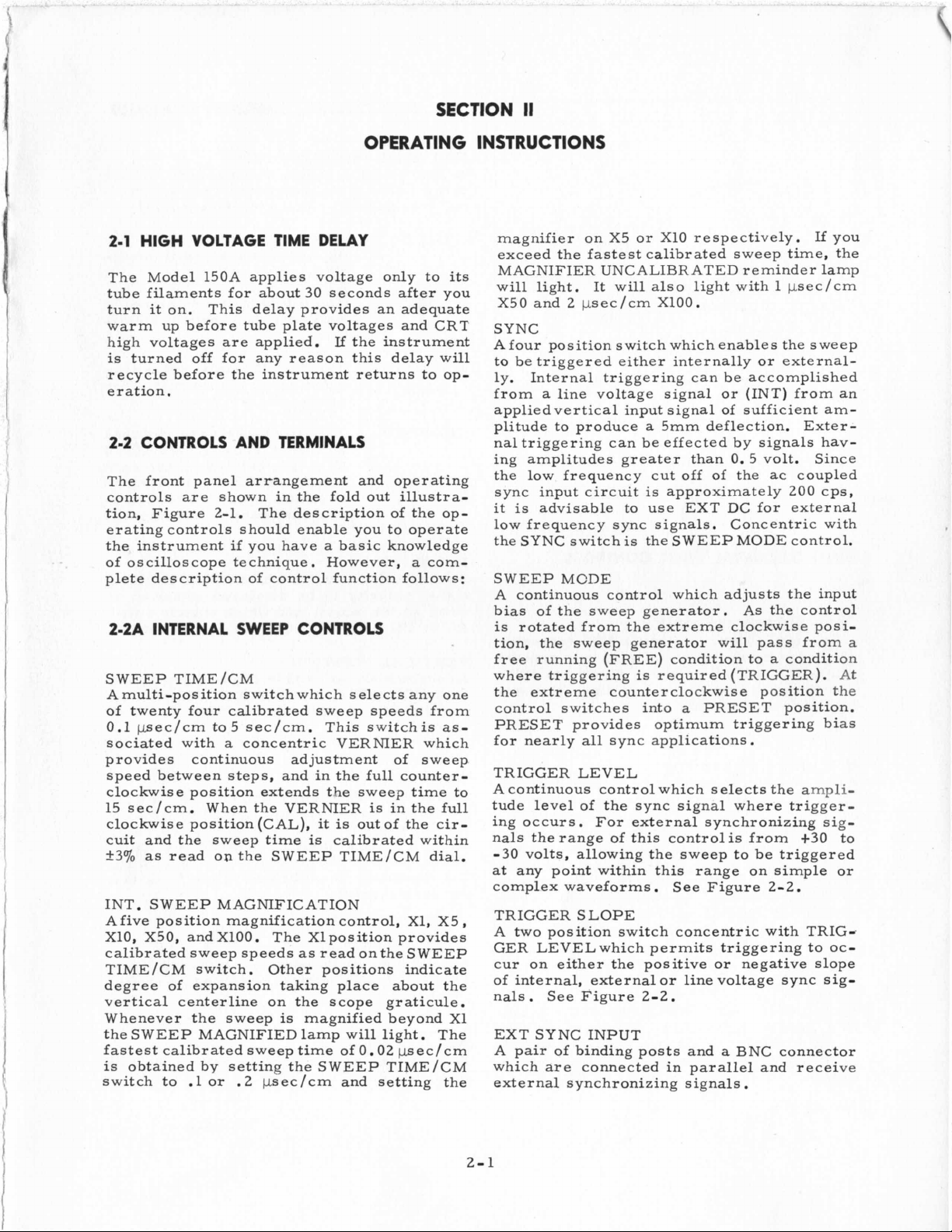
2-1
HIGH VOLTAGE TIME DELAY
The Model 150A applies voltage only to
tube filaments for about
it
turn
warm up before tube plate voltages and CRT
high voltages are applied.
is
recycle before the instrument returns to operation.
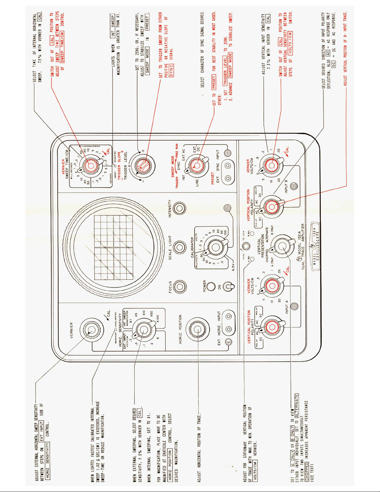
2-2
The front panel arrangement and operating
controls are shown in the fold out illustration, Figure 2-1. The description of the operating controls should enable you to operate
the instrument
of oscilloscope technique. However,
plete description of control function follows:
on. This delay provides an adequate
turned off for any reason this delay will
CONTROLS AND TERMINALS
if
you have a basic knowledge
30
seconds after you
If
the instrument
2-ZA INTERNAL SWEEP CONTROLS
SWEEP TIME/CM
Amulti-position switchwhich selects any one
of twenty four calibrated sweep speeds from
0.1 pec/cm to5 sec/cm. This switchis
sociated with a concentric VERNIER which
provides continuous adjustment of sweep
speed between steps, and in the full counterclockwise position extends the sweep time to
is
15 sec/cm. When the VERNIER
clockwise position (GAL),
cuit and the sweep time
k370
as
read
on
the SWEEP TIME/CM dial.
INT. SWEEP MAGNIFICATION
Afive position magnification control,
X10, X50, and X100. The Xlposition provides
calibrated sweep speeds
TIME /CM switch. Other positions indicate
degree of expansion taking place about the
vertical centerline on the scope graticule.
Whenever the sweep
the SWEEP MAGNIFIED lamp will light. The
fastest calibrated sweep time of
is
obtained by setting the SWEEP TIME/CM
switch to
.1
or
.2
psec/cm and setting the
it
is
is
calibrated within
as
read onthe SWEEP
is
magnified beyond X1
in the full
out of the cir-
0.02
pec/cm
a
X1,
its
com-
as-
X5,
II
magnifier on X5 or
exceed the fastest calibrated sweep time, the
MAGNIFIER UNCALIBRATED reminder lamp
will light. It will also light with 1 psec/cm
X50 and 2 psec/cm X100.
SYNC
Afour position switch which enables the sweep
to be triggered either internally or externally. Internal triggering can be accomplished
a
from
applied vertical input signal of sufficient amplitude to produce
nal triggering can be effected by signals having amplitudes greater than
the low frequency cut
sync input circuit
it
low frequency sync signals. Concentric with
the SYNC switch
SWEEP MCDE
A
bias of the sweep generator. As the control
is
tion, the sweep generator will pass from
free running (FREE) condition to a condition
where triggering
the extreme counterclockwise position the
control switches into
PRESET provides optimum triggering bias
for nearly
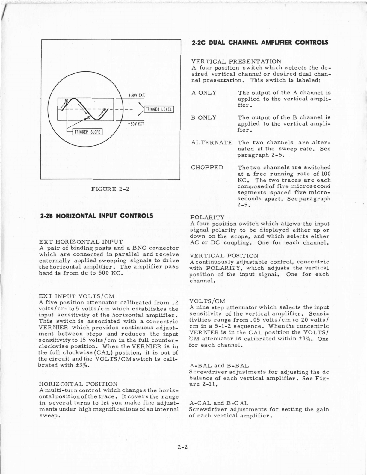
TRIGGER LEVEL
A continuous control which selects the ampli-
tude level of the sync signal where trigger-
ing occurs. For external synchronizing sig-
nals therange of this controlis from
-30
at
complex waveforms. See Figure 2-2.
TRIGGER SLOPE
A two position switch concentric with TRIGGER LEVELwhich permits triggering to occur on either the positive
of internal, external or line voltage sync signals. See Figure 2-2.
EXT
A
which are connected in parallel and receive
external synchronizing signals.
line voltage signal or (INT) from an
is
advisable to use
continuous control which adjusts the input
rotated from the extreme clockwise posi-
all
sync applications.
volts, allowing the sweep to be triggered
any point within this range on simple or
SYNC
pair of binding posts and a BNC connector
INPUT
X1O
respectively. If you
a
5mm deflection. Exter-
0.
5 volt. Since
off
of the ac coupled
is
approximately 200 cps,
EXT
DC for external
is
the SWEEP MODE control.
is
required (TRIGGER). At
a
PRESET position.
or
negative slope
+30
to
a
2-1
Page 9
2-2C
DUAL
VERTICAL PRESENTATION
A four position switch which selects the desired vertical channel or desired dual channel presentation.
CHANNEL AMPLIFIER CONTROLS
This switch
is
labeled:
FIGURE 2-2
2-2B
HORIZONTAL INPUT CONTROLS
EXT HORIZONTAL INPUT
a
A pair of binding posts and
which are connected in parallel and receive
externally applied sweeping signals to drive
the horizontal amplifier. The amplifier pass
is
band
from dc to
500
KC.
BNC connector
A ONLY
B ONLY
ALTERNATE
CHOPPED
POLARITY
A four position switch which allows the input
signal polarity to be displayed either up or
down on the scope, and which selects either
AC or
VERTICAL POSITION
A continuously adjustable control, concentric
with POLARITY, which adjusts the vertical
position of the input signal. One for each
channel.
DC
The output of the A channel
applied to the vertical amplifier.
The output of the B channel
applied to the vertical ampli-
fier.
The two channels are alter-
at
nated
paragraph 2-5.
The two channels
at
a
KC.
composed of five microsecond
segments spaced five microseconds apart. See paragraph
2-5.
coupling. One for each channel.
the sweep rate. See
are
switched
free running rate
The
two
traces are each
of
100
is
is
EXT INPUT VOLTS/CM
A five position attenuator calibrated from .2
volts/cm to 5 volts/cm which establishes the
input
This switch
VERNIER which provides continuous ad just
ment between steps and reduces the input
sensitivity to 15 volts /cm in the full counterclockwise position. When the VERNIER
the full clockwise (CAL) position,
the circuit and the VOLTS/CM switch
brated with
HORIZONTAL POSITION
A multi-turn control which changes the horiz-
ontalpositionof the trace. It covers the range
in several turns to let you make fine adjustments under high magnifications of an internal
sweep.
sensitivity of the horizontal amplifier.
is
associated with a concentric
is
it
is
out of
is
cali-
+30/0.
in
VOLTS /CM
A nine step attenuator which selects the input
sensitivity of the vertical amplifier.
tivities range from. 05 trolts/cm to 20 volts/
a
cm in
-
VERNIER
‘CM
for each channel.
A-BAL and B-BAL
Screwdriver adjustments for adjusting the dc
balance of each vertical amplifier.
ure
A-CAL and B-CAL
Screwdriver adjustments for setting the gain
of each vertical amplifier.
2-2
5-1-2 sequence.
is
in the CAL position the VOLTS/
attenuator is calibrated within
2-11.
Whenthe concentric
Sensi-
+3oJO.
One
See Fig-
Page 10
2-2D
CRT PANEL CONTROLS
FOCUS
01s
Contr
trace resolution,
RESET
A terminal which can receive an external
pulse to rearm the single sweep circuit. Pulse
characteristics required
peakwithno overshoot;
=
+15 to +25 volts
2
to 4 pseconds width.
INTENSITY
Controls trace brightness.
SCALE LIGHT
Adjusts brightness of graticule lines.
CALIBRATOR
a
at
1000
the
rise
A multi-position switch which adjusts
cps square wave from 0.2 millivolts to 100
volts in
+3
of
adjacent terminal and can be used to calibrate the deflection sensitivity of the vertical
and horizontal amplifier
and decay times are each less than 1 micro-
second. The square wave output may also be
used to adjust the divider probe for frequency
response.
a
2-5-10 sequence with an accuracy
70.
The output voltage appears
.
Square wave
2-2E TOP ACCESS CONTROLS
The following controls and terminals are accessible through the top access door of the
instrument cabinet.
Horizontal and vertical deflection plates.
A terminal for CRT intensity (Z-axis) modulation
FUSE
Line fuse
Thermal cutout with resetting button.
2-3
OPERATING PROCEDURES
Basic operating procedures are described by
illustrations
steps in eachcase. The
are complete. Others are arranged to supplement the
tions possible in using the oscilloscope.
index to these illustrations follows:
FIG.
2-3
2 -4
2-5
2-6
2-7
2
-8
2
-9
2-10
2-1 1
2-12
2-13
2-14
2-15
2-16
2-17
(Fl)
6-1/4 amp slo-blo.
which are keyed to procedural
first
twoprocedures
first
two by showing the varia-
TITLE
Internal Sweep
Internal Sweep
Internal Sweep Magnification
External Horizontal Input
Vertical Input
Adjusting Divider Probe
Removing CRT Bezel
Aligning Scope Trace with Graticule
Vertical Balance Adjustment
Direct Connection to
Capacitive Coupling to CRT Plates
Single Sweep Operation
Delayed Sweep Operation
Vertical VOLTS /CM Calibration
External Intensity Modulation
--
Internal Sync
--
External Sync
--
Dual Trace
CRT
Plates
An
SAWTOOTH OUT
A terminal which provides
voltage corresponding to the sweep.
GATE OUT
A terminal which provides
voltage for the duration of the sweep.
SINGLE-NORMAL
A switch which selects either normal or sin-
gle sweep operation. In single sweep posi-
tion the circuits are arrangedto sweep once
a
after
tive until manually or
The ARMED lamp lights when the single sweep
circuit
trigger signal and then remain inopera-
is
ready for a trigger.
a
sawtooth output
a
positive gate
electronically reset.
2-4
VERTICAL AC OR DC COUPLING
Under most conditions AC coupling will be
used.
without regard for the dc levels involved. In
the AC position the input signal (vertical or
external sync)
through
component from the input wave. This coup-
ling circuit has
cps; however, to avoid degrading input pulses
or square waves below 10 cps
to use dc coupling.
When you want to look
to
rundown in circuit work, or in mechanical
work where the output from
a
It permits high gain to be employed
is
coupled to the instrument
a
capacitor which removes the dc
a
low frequency cut off
it
is
advisable
at
waveforms relative
a
dc level; for example, observing a Miller
a
transducer has
dc component; use dc coupling.
2-3
at
2
Page 11
2-5
USE
OF
CHOPPED
OR
ALTERNATE SWEEP
CHOPPED and ALTERNATE VERTICAL PRG
two
SENTATIONare used topresent
electrical phenomona, which are related in
frequency or rate of recurrence, to the
cilloscope CRT for simultaneous viewing.
ALTERNATE may be used whenever sweep
time and rate of recurrence are rapid enough
is
and screenpersistence
vent objectionable flicker. CHOPPED PRESENTATION should be used
NATE position
on the screen as the inputs are switched after
a
flickering effect
long enoughto pre-
if,
separate
os-
in the ALTER-
is
noticeable
each sweep. When two related signals are
being presented to the oscilloscope for
multaneous viewing using either CHOPPED
or ALTERNATE VERTICAL PRESENTATION
the 150A should be synchronized externally.
Insome cases
different input waves not related infrequency.
In this instance the 150A may be synchronized
internally, triggering automatically
one signal then from the other
is
dure
may cause noticeable deterioration of the
quality
may be improved byadjusting the VERTICAL
POSITION controls
not ordinarily recommended since
of
it
may be desirable to view two
first
.
This proce-
the presentation. Quality generally
so
that the traces overlap.
si-
from
it
2-4
Page 12
INTERNAL SWEEP - INTERNAL SYNCHRONIZATION
-0-
I
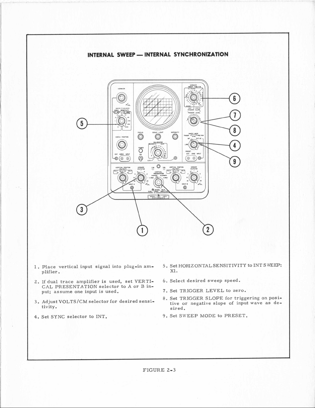
1.
Place vertical input signal into plug-in am-
plifier.
2.
If dual trace amplifier
CAL PRESENTATION selector to
put; assume one input is used.
3
.
Adjust VOLTS/CM selector for desired sensitiv it
y
.
4.
Set SYNC selector to INT.
is
used, set VERTI-
A
or
B
in-
FIGURE
5.
Set HORIZONTAL SENSITIVITY to INT
x1.
6.
Select desired sweep speed.
7.
Set TRIGGER LEVEL to zero.
8.
Set TRIGGER SLOPE for triggering on positive or negative slope
sired.
9.
Set SWEEP MODE to PRESET.
2-3
of
input wave
SWEEP:
as
de-
Page 13
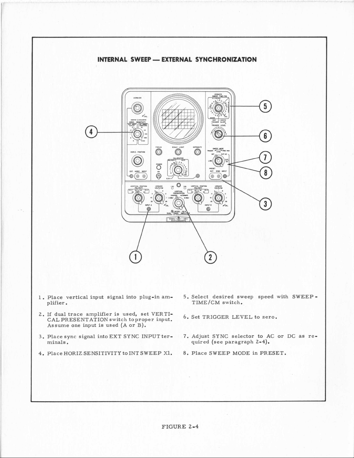
INTERNAL SWEEP - EXTERNAL SYNCHRONIZATION
1.
Place vertical input signal into plug-in am-
plifier.
2.
If dual trace amplifier
CALPRESENTATION switch toproper input.
Assume one input
3
.
Place sync signal into EXT SYNC INPUT terminals
4.
Place HORIZ SENSITIVITY to INT SWEEP X1.
.
is
is
used (A or
used, set VERTI-
B).
FIGURE
5.
Select desired sweep speed with SWEEPTIME/CM switch.
6.
Set TRIGGER LEVEL to zero.
7.
Adjust SYNC selector to AC or DC
quired (see paragraph
8.
Place SWEEP MODE in PRESET.
2-4
2-4).
as
re-
Page 14
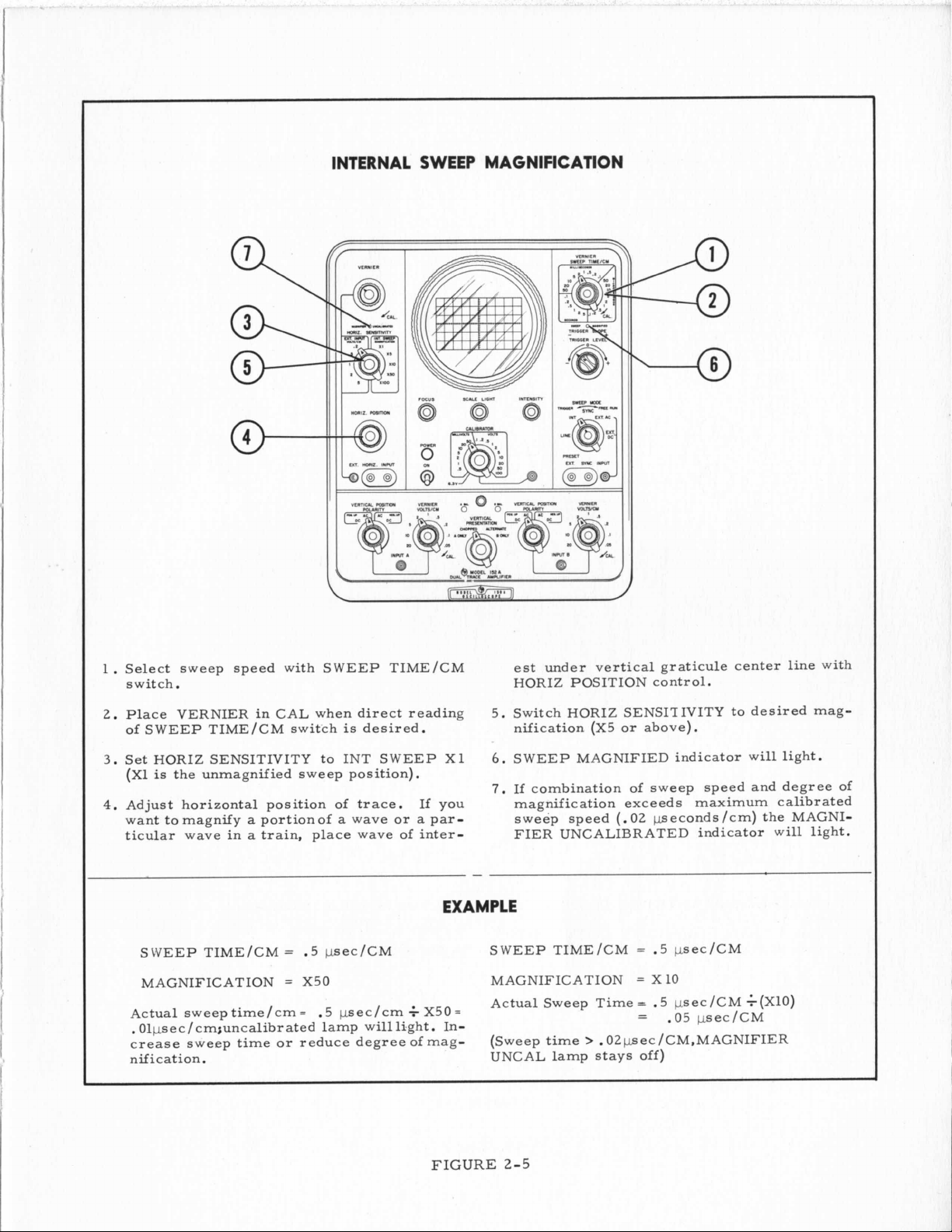
INTERNAL SWEEP MAGNIFICATION
I
1.
Select sweep speed with SWEEP TIME/CM
switch.
Place
2.
of SWEEP TIME/CM switch
3.
Set HORIZ SENSITIVITY to INT SWEEP X1
(X1
4.
Adjust horizontal position of
want
ticular wave in
nification. UNCAL lamp stays off)
VERNIER in CAL when direct reading
is
the unmagnified sweep position).
to
magnify a portionof a wave or a par-
a
train, place wave
SWEEP TIME/CM
MAGNIFICATION
Actual sweeptime/cm=
.
Olpsec / cm;uncalibr ated lamp will light. In-
crease sweep time or reduce degree of mag-
=
=
is
desired.
of
G
If you
inter-
X50=
trace.
.5 psec/CM
X50 MAGNIFICATION
psec/cm
.5
est under vertical graticule center line with
HORIZ POSITION control.
5. Switch HORIZ SENSITIVITY to desired magnification (X5 or above).
6.
SWEEP MAGNIFIED indicator will light.
7.
If
combination of sweep
magnification exceeds maximum calibrated
sweep speed
FIER UNCALIBRATED indicator will light.
SWEEP TIME/CM
Actual Sweep Time
(Sweep
time
>
.02pec/CM,MAGNIFIER
speed and degree of
(.02
peconds/cm) the MAGNI-
=
.5 psec/CM
=
X10
=
.5 psec/CM $(XlO)
=
.05
psec/CM
FIGURE
2-5
Page 15
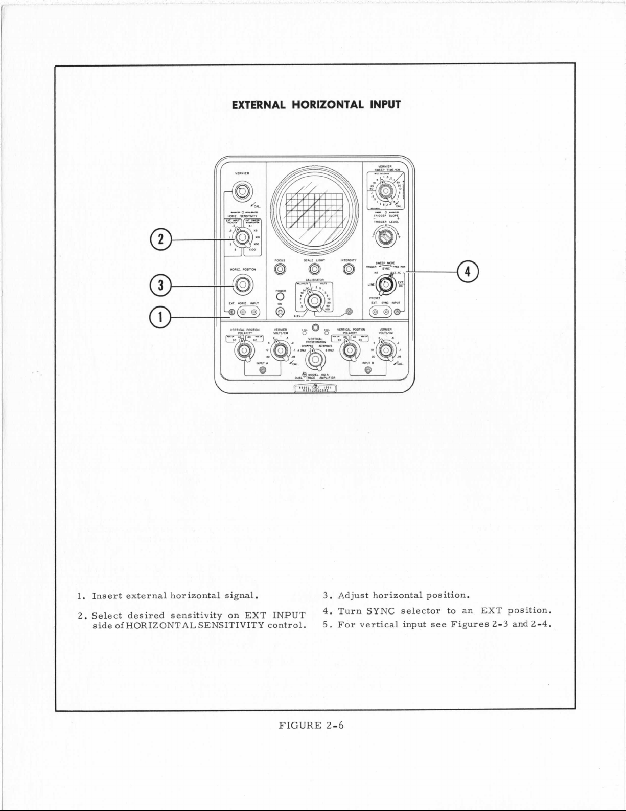
EXTERNAL HORIZONTAL INPUT
(if
VLINILI
1.
Insert external horizontal signal.
2.
Select desired
side
of
HORIZONTAL SENSITIVITY control,
sensitivity
on
EXT
INPUT
FIGURE
3.
Adjust horizontal position.
4.
Turn SYNC selector to an EXT position.
5.
For vertical input see Figures
2-3
2-6
and
2-4.
Page 16
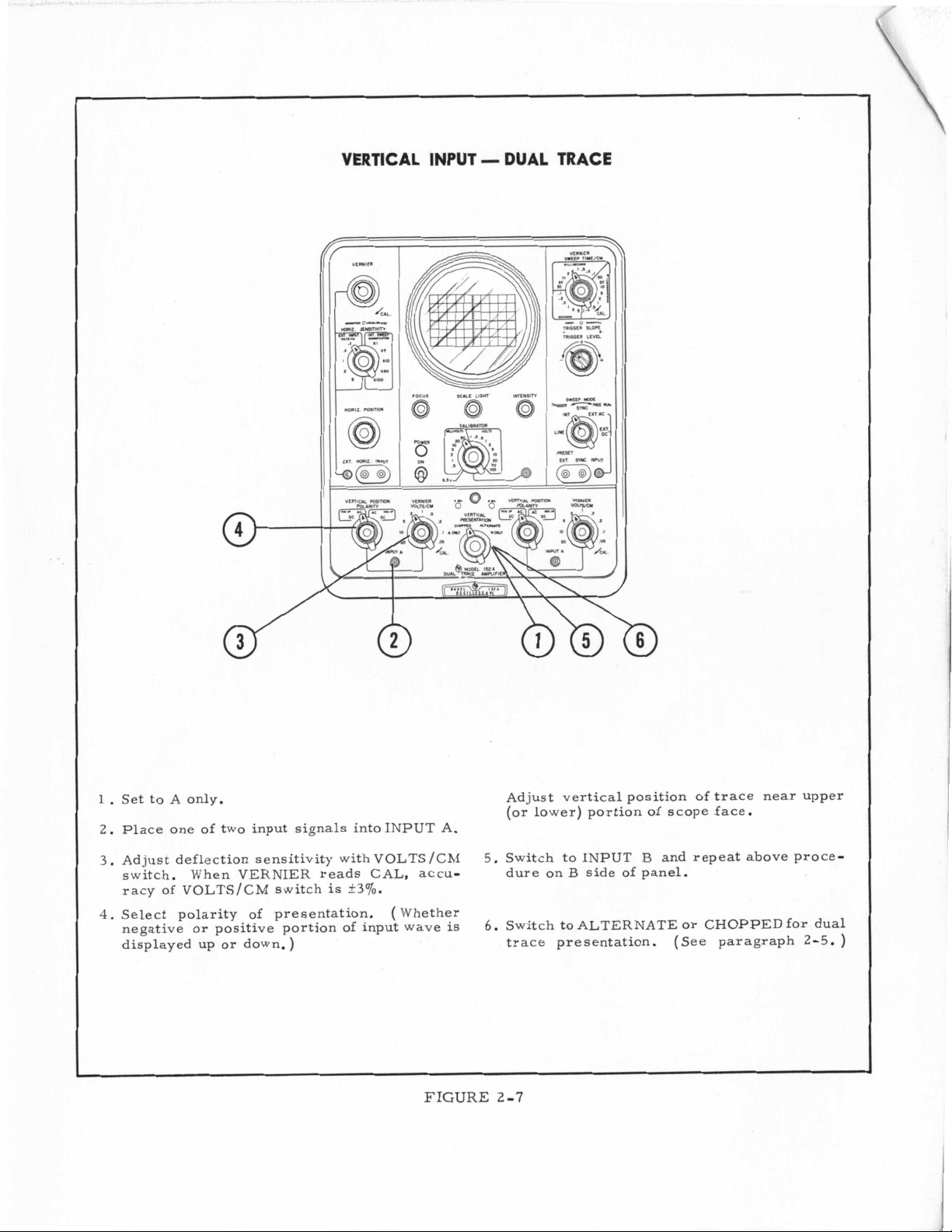
VERTICAL INPUT - DUAL TRACE
1.
Set to A only.
2.
Place one of two input signals intoINPUT A.
3.
Adjust deflection sensitivity with VOLTS /CM
switch. When VERNIER reads CAL, accuracy of VOLTS/CM switch
4.
Select polarity of presentation.
negative or positive portion of input wave
displayed up or down.)
is
+3%.
(
Whether
is
FIGURE
Adjust vertical position of trace near upper
(or lower) portion of scope face.
5.
Switch to INPUT B and repeat above procedure on
6.
Switch to ALTERNATE or CHOPPED for dual
trace presentation.
B
side of panel.
(See paragraph
2-7
2-5.
)
Page 17
..
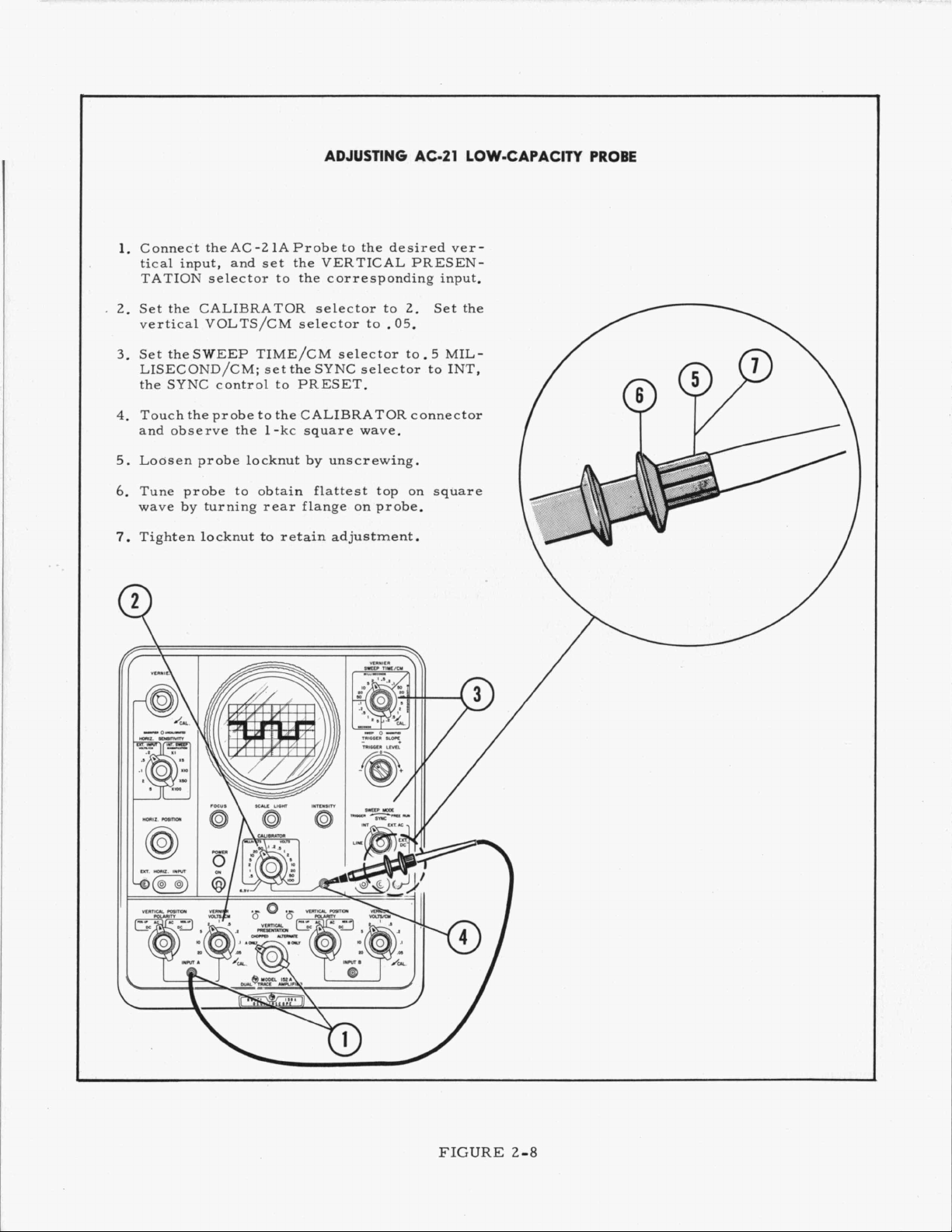
Connect theAC-21AProbe to the desired ver-
lo
tical input, and set the VERTICAL PRESENTATION selector to the corresponding input.
Set the CALIBRATOR selector to
2.
vertical VOLTS/CM selector to
Set the SWEEP TIME/CM selector to. 5 MIL-
3.
2.
.05.
LISECOND/CM; set the SYNC selector to INT,
the SYNC control to PRESET.
Touch the probe to the CALIBRATOR connector
4.
and observe the 1-kc square wave.
I
Set the
.-
Loasen probe locknut by unscrewing.
5.
Tune probe to obtain flattest top on square
6.
wave by turning rear flange
Tighten locknut to retain adjustmenti
7.
on
probe.
t:
/
II
'
FIGURE
2-8
Page 18
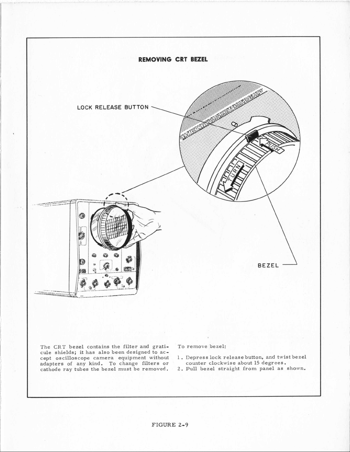
REMOVING CRT BEZEL
LOCK
RELEA
The CRT bezel contains the filter and graticule shields;
cept oscilloscope camera equipment without
adapters of any kind.
cathode ray tubes the bezel must be removed,
it
has also been designed to ac-
To
change filters or
FIGURE
To
remove bezel:
1
.
Depress lock release button, and twist bezel
counter clockwise about 15 degrees
2.
Pull bezel straight from panel
2-9
.
as
shown.
Page 19
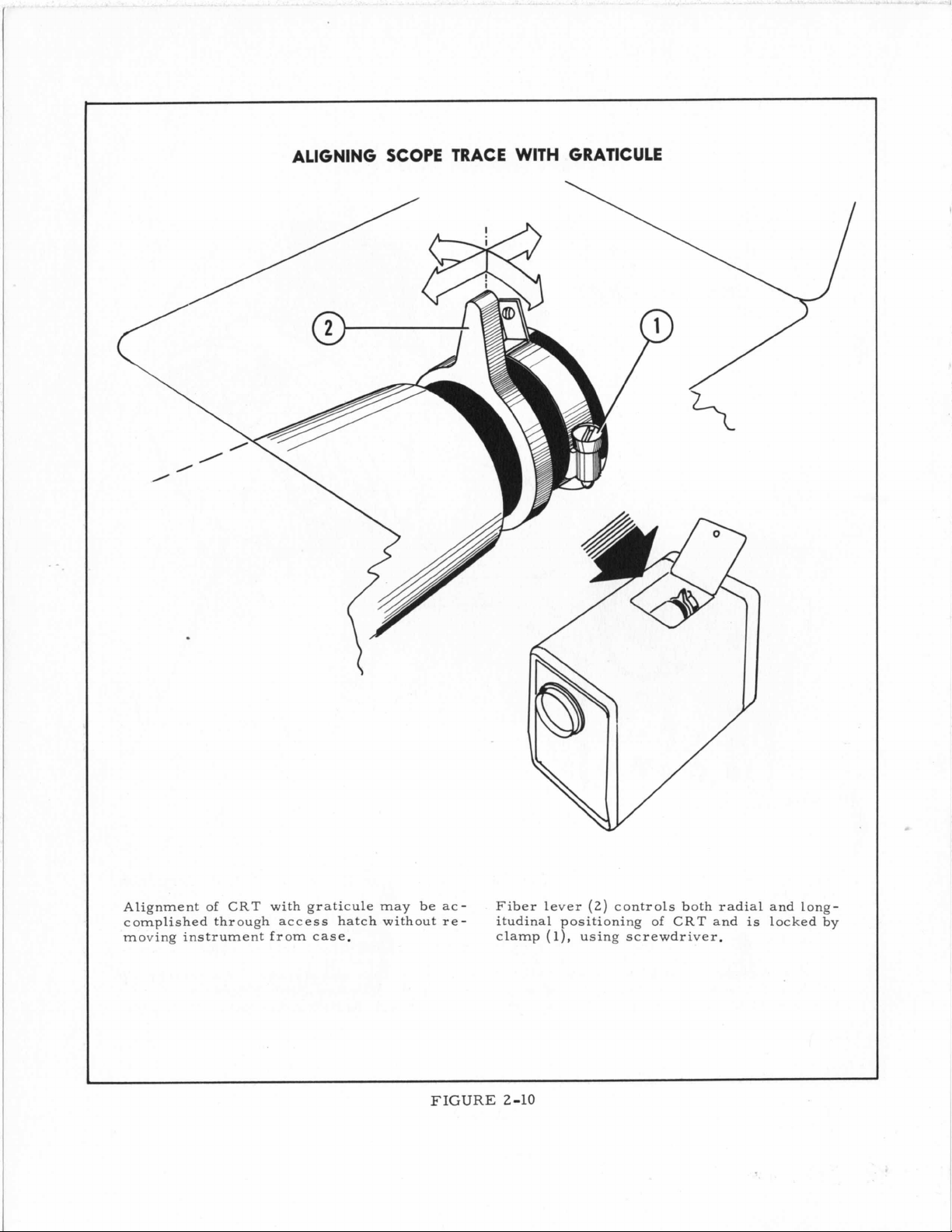
ALIGNING SCOPE TRACE
WITH
GRATICULE
Alignment
complished through access hatch without removing instrument from case.
of
CRT
with graticule may be ac-
FIGURE
(2)
Fiber lever
itudinal positioning
clamp
(l),
controls both radial and
using screwdriver.
2-10
of
CRT
and
is
locked by
long-
Page 20
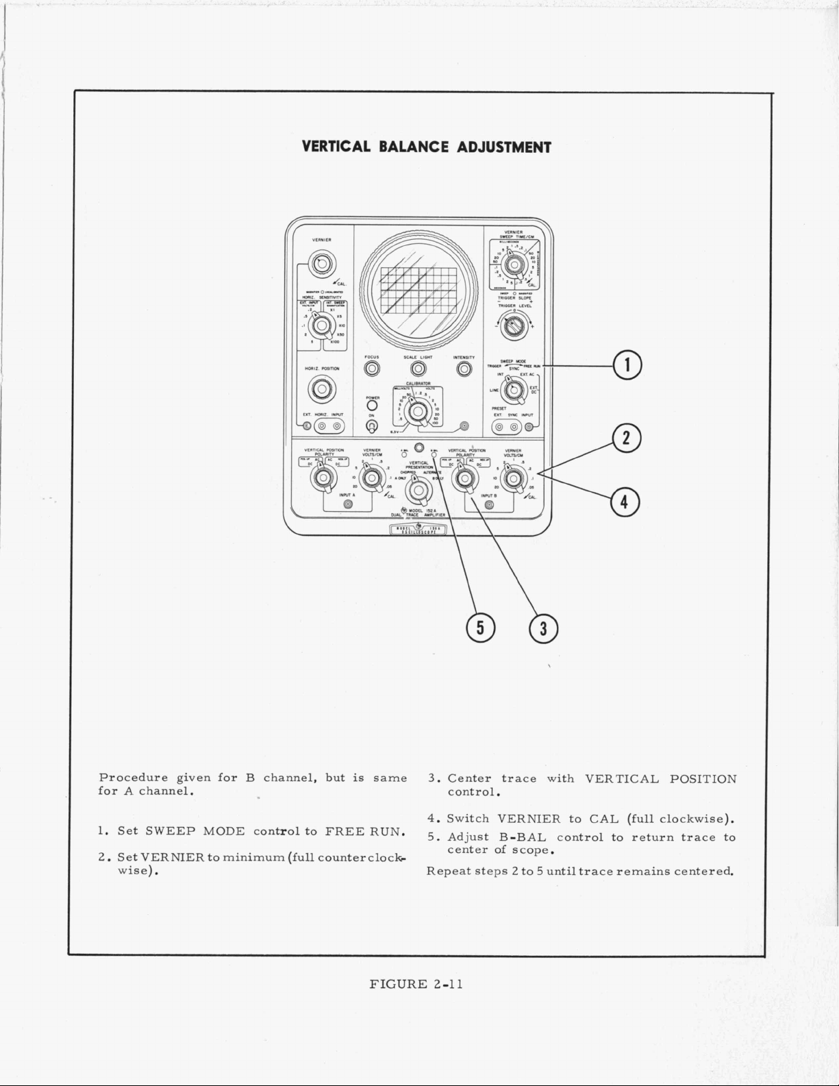
VERTICAL BALANCE ADJUSTMENT
Procedure given for B channel, but
A
for
1. Set SWEEP MODE control to FREE RUN.
2
channel.
.
Set VERNIER to minimum (full counterclock
.
wise)
is
same
FIGURE
3
.
Center trace with VERTICAL POSITION
control.
4.
Switch VERNIER to
5.
Adjust B-BAL control to return trace to
center of scope.
2
Repeat steps
2-11
to 5 until trace remains centered.
CAL
(full clockwise).
Page 21
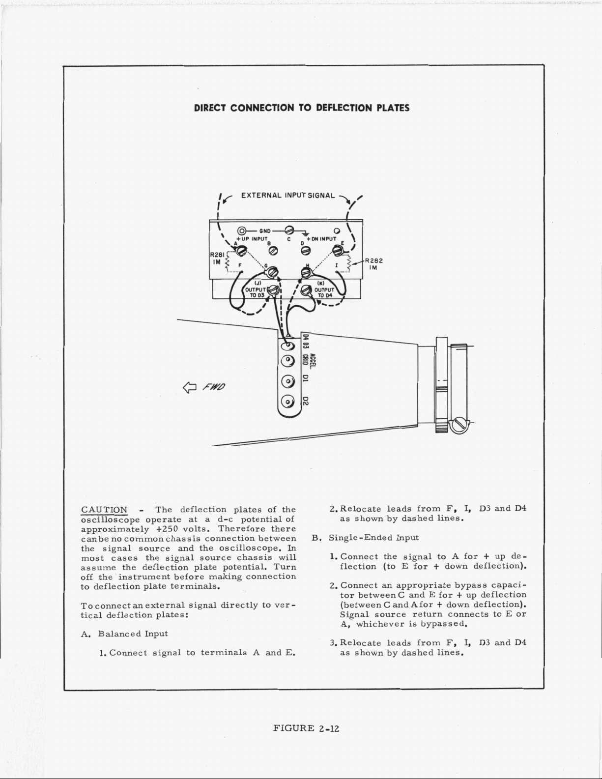
DIRECT CONNECTION
//
EXTERNAL INPUT SIGNAL
I
TO
DEFLECTION
PLATES
'R282
IM
CAUTION
oscilloscope operate
approximately +250 volts. Therefore there
canbe no commonchassis connection between
the signal source and the oscilloscope. In
most cases the signal source chassis
assume the deflection plate potential. Turn
off the
to deflection plate terminals.
To connect an external signal directly to ver
tical deflection plates:
A. Balanced Input
1,Connect signal to terminals A and
-
The deflection plates of the
at
a
d-c potential of
will
'
instrument before making connection
,
E.
FIGURE
-
2.Relocate leads from
as shown by dashed lines.
B.
Single-Ended Input
1.Connect the signal to A for + up deflection (to E for + down deflection).
2.
Connect an appropriate bypass capacitor betweenC and
(between C and Afor
Signal source return connects to
A, whichever is bypassed.
3.
Relocate leads from
as
shown by dashed lines.
2-12
F,
I,
D3
E
for t up deflection
+
down deflection).
F,
I,
D3
and
and
E
D4
or
D4
Page 22
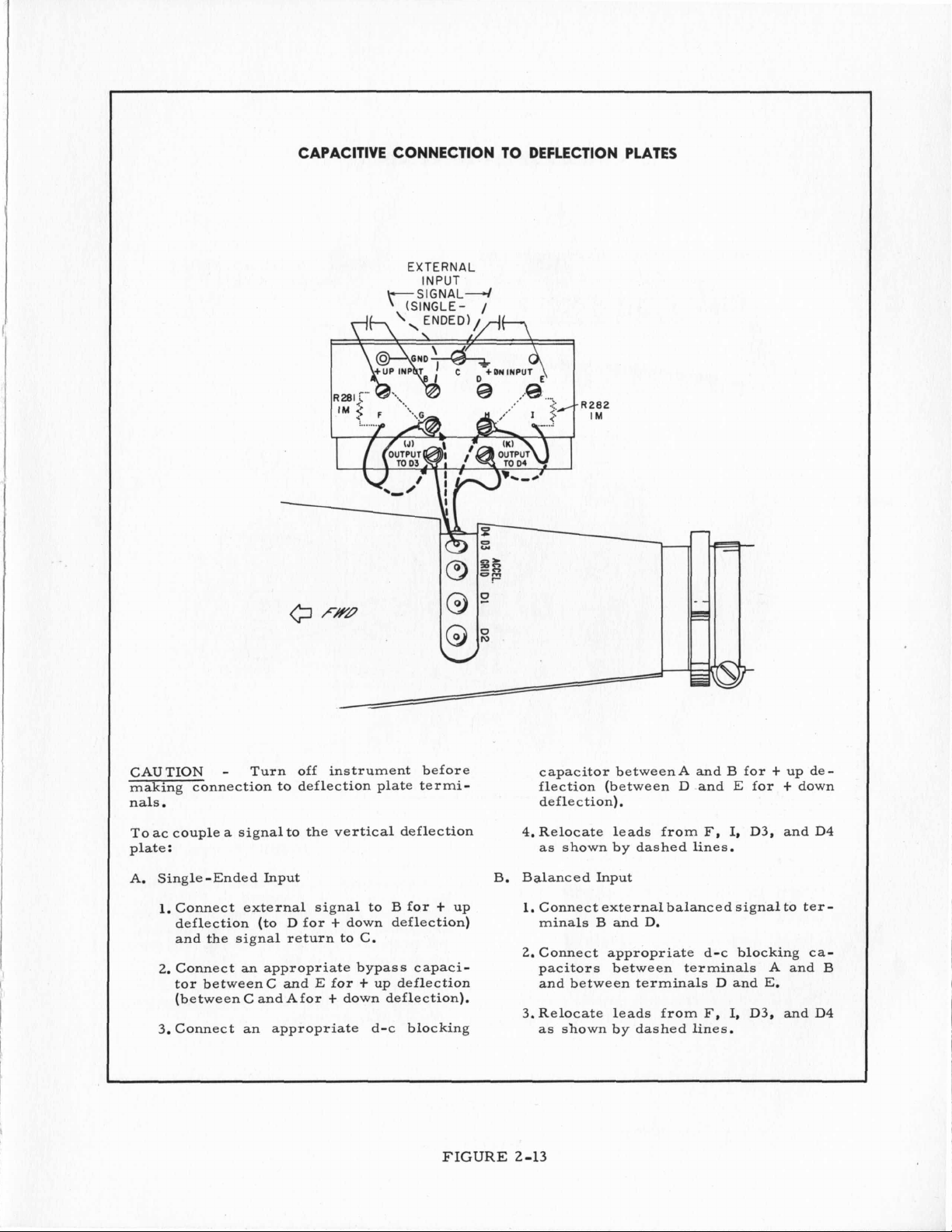
CAPACITIVE CONNECTION
EXTERNAL
INPUT
SIGNAL^
.
(SINGLE-
/
TO
DEFLECTION
-R282
IM
PLATES
CAUTION
-
Turn off instrument before
making connection to deflection plate terminals.
ac
couple a signal to the vertical deflection
To
plate
:
A. Single-Ended Input
1.
Connect external signal to B for t up
deflection (to D for
and the signal return to
2.
Connect an appropriate bypass capaci-
tor betweenC and E for
t
down deflection)
C.
t
up deflection
(between C and Afor t down deflection).
3. Connect an appropriate d-c blocking
FIGURE
capacitor betweenA and B for
flection (between D and
deflection).
F,
4.Relocate leads from
as
shown by dashed lines.
I,
B. Balanced Input
1.
Connect external balanced signal to
minals B and D.
2.
Connect appropriate d-c blocking
pacitors between terminals A and B
and between terminals
3.Relocate leads from
as
shown
by dashed lines.
D and
F,
I,
2-13
t
E
up de-
for t down
D3, and D4
E.
D3, and D4
ter-
ca-
Page 23
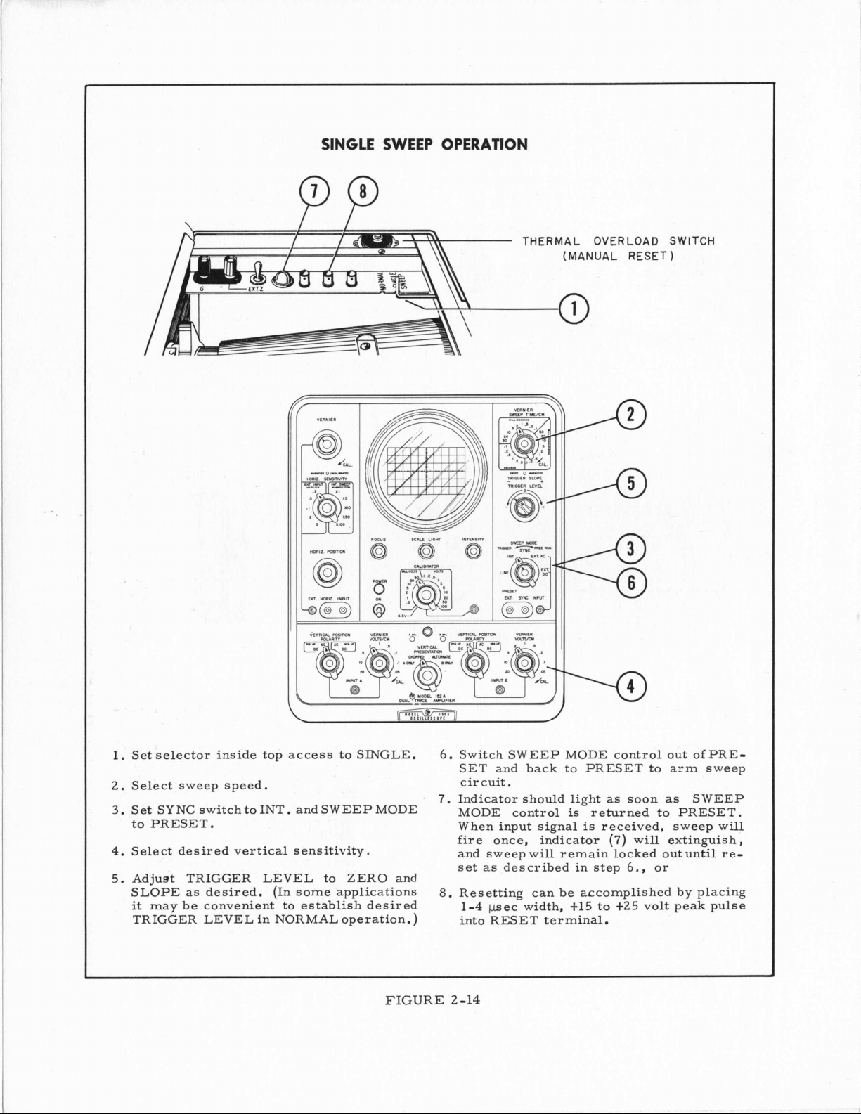
SINGLE SWEEP OPERATION
PP
THERMAL OVERLOAD SWITCH
(MANUAL RESET
1
1.
Set selector inside top access to SINGLE.
2.
Select sweep speed.
3.
Set SYNC switch to INT. and SWEEP MODE MODE control
to PRESET.
4.
Select desired vertical sensitivity.
5.
Adjust TRIGGER LEVEL to ZERO and
SLOPE
it
TRIGGER LEVEL in NORMAL operation.)
as
may be convenient to establish desired
desired.
(In
some applications
FIGURE
6.
Switch SWEEP MODE control out ofPRESET and back to PRESET to arm sweep
circuit
7.
Indicator should light
When input signal
fire
once, indicator
and sweep will remain locked out until re-
set
as described in step
8.
Resetting can be accomplished by placing
1-4
pec
into RES ET terminal
2-14
.
width,
as
soon
as
is
returned to PRESET.
is
received, sweep will
(7)
will extinguish,
6.,
or
t15
to
t25
volt peak pulse
.
SWEEP
Page 24
4
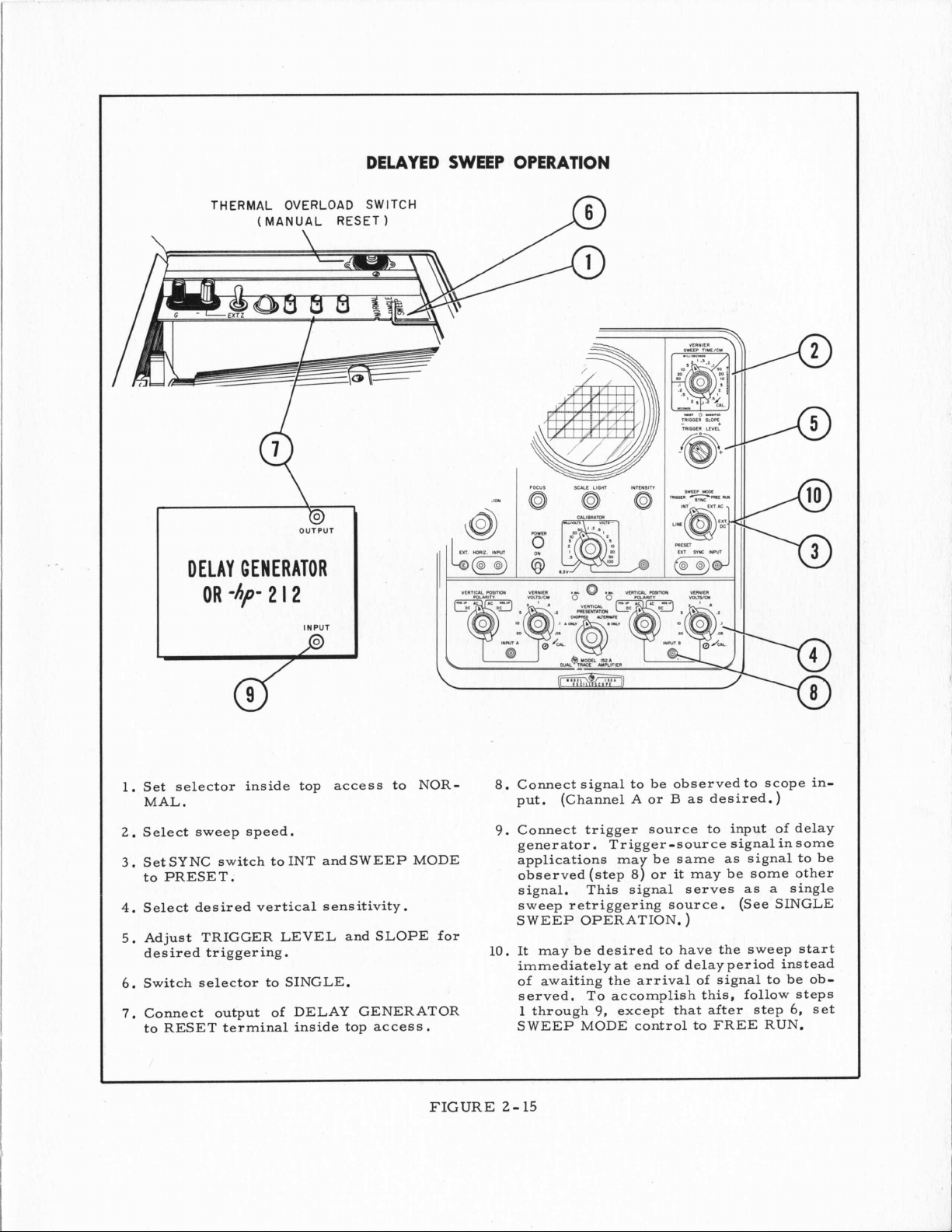
DELAYED SWEEP OPERATION
D
OUTPUT
DELAY GENERATOR
-hp-
2
OR
I2
INPUT
J3
1.
Set selector inside top access to NORMAL.
2.
Select sweep speed.
3.
Set SYNC switch to INT and SWEEP MODE
to PRESET.
4.
Select desired vertical sensitivity.
5.
Adjust TRIGGER LEVEL and SLOPE for
desired triggering.
6.
Switch selector to SINGLE.
7.
Connect output of DELAY GENERATOR
to RESET terminal inside top
access.
8.
Connect signal to be observed to scope in-
(Channel A or
put.
9.
Connect trigger source to input of delay
generator. Trigger-source signal in some
applications may be same
observed(step
signal. This signal serves
sweep retriggering source. (See SINGLE
SWEEP OPERATION.
10.
It may be desired to have the sweep
immediately
of awaiting the arrival of signal to be observed.
1 through
SWEEP MODE control to FREE RUN.
at
To
accomplish this, follow steps
9,
except that after step
8)
end
B
as
desired.)
as
or
it
may be some other
)
of
delayperiod instead
signal
as
a
to
be
single
start
6,
set
FIGURE
2-
15
Page 25
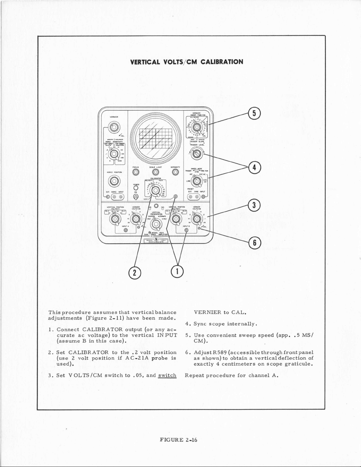
VERTICAL VOLTS/CM CALIBRATION
This procedure assumes that vertical . alance
adjustments (Figure 2- 11) have been made.
1.
Connect CALIBRATOR output (or any accurate ac voltage) to the vertical INPUT
(assume B in this case).
2. Set CALIBRATOR to the .2 volt position
if
2 volt position
(use
AC-21A probe
used).
3.
Set VOLTS/CM switch to
.05,
and switch
FIGURE
VER
TIER to CAL.
4.
Sync scope internally.
5.
Use convenient sweep speed (app. .5 MS/
CM).
6.
is
Adjust R589 (accessible through frontpanel
as shown) to obtain a verticaldeflection of
exactly
4
centimeters on scope graticule.
Repeat procedure for channel A.
2-16
Page 26
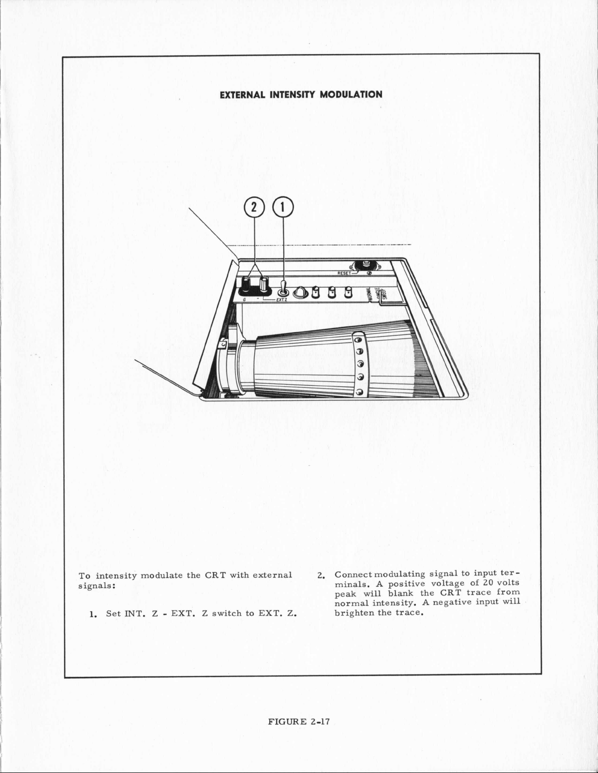
EXTERNAL INTENSITY MODULATION
I
To intensity
signals
:
1.
Set
INT.
modulate the CRT with external
Z
-
EXT. Z switch to EXT.
FIGURE
Z.
Connect modulating signal to input ter-
2.
minals.
peak will
normal intensity.
brighten the trace.
2-17
A
positive voltage of
blank
the CRT trace from
A
negative input will
20
volts
Page 27
1
INT.
SYNC
I
VERTICAL
CRT
PLATES
\
HORIZONTAL
AMPLIFIER
HORIZONTAL
FIGURE
CAT
PLATES
3-1
TO
ASTlCMATlSY
3
-0
Page 28
SECTION
111
THEORY
3-1
GENERAL CONTENT
This section contains a brief description of
the overall operationof the 150A Oscilloscope,
descriptions of each major section and detailed explanations of the Feedback Integrator
Sawtooth Generator andSchmitt Trigger. The
is
description for each major section
ported by
voltage
and when necessary, a switch detail diagram,
at
the rear of the manual. The material in
this section
3-2 Overall Operation and Circuit
3-3 Synchronizing Circuit
3-4 Sweep Generator
3-5 FeedbackIntegrator and Diode
3-6
3-7
3-8 Main Vertical Amplifier
3-9
3- 10 Calibrator
3-
3- 12 Regulated High-Voltage Power
3-13 Single Sweep And Delayed
3-2
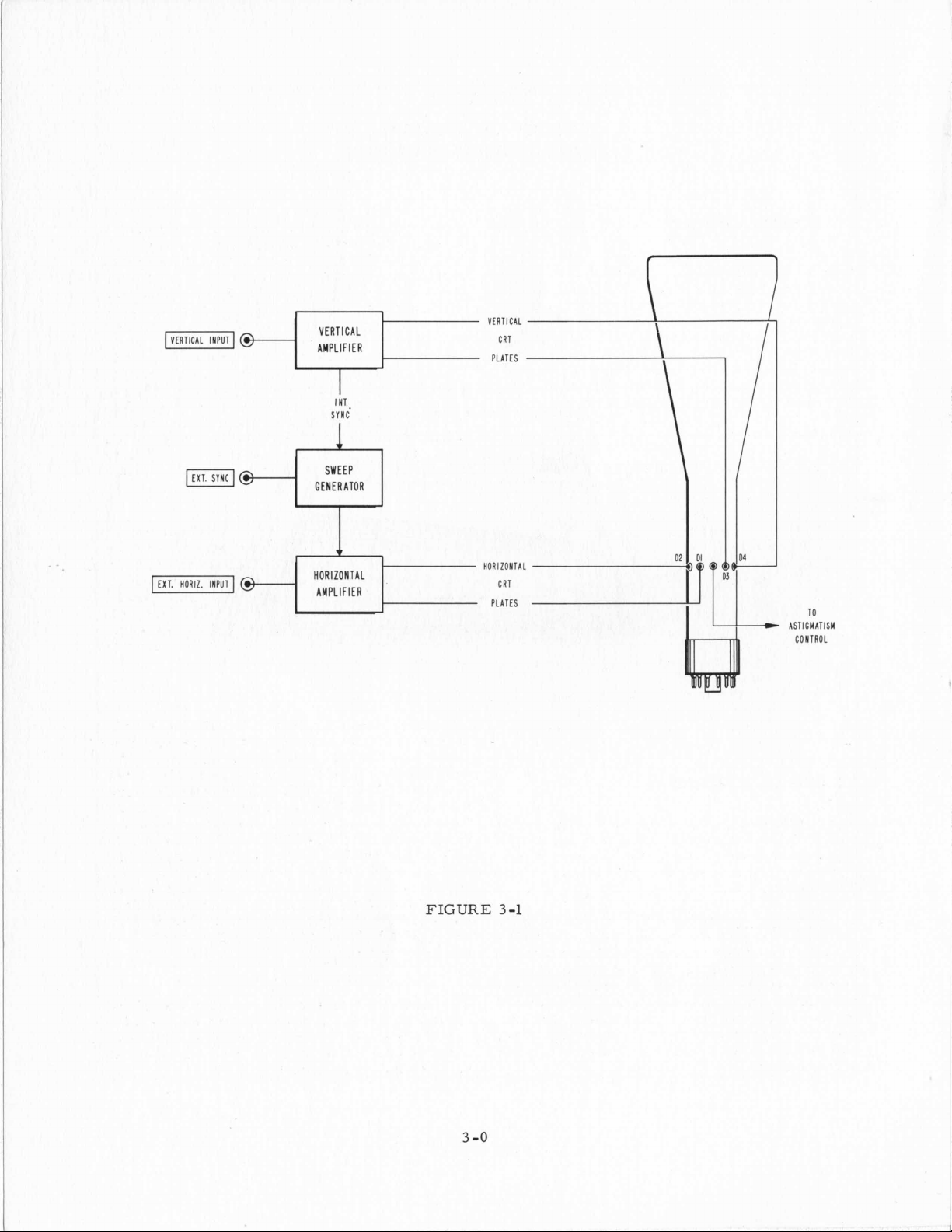
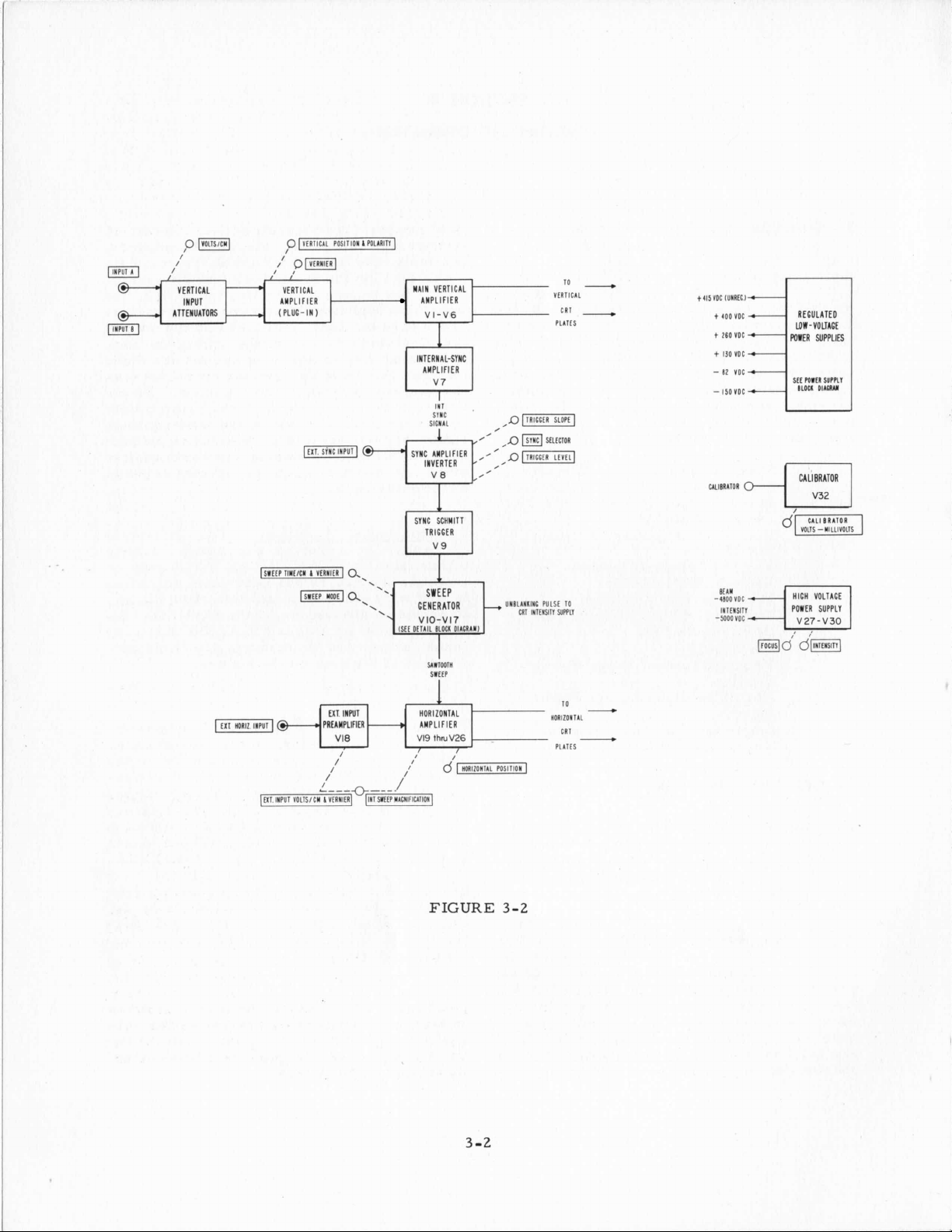
OVERALL OPERATION
The simplified block diagram in Figure 3-1
shows the basic signal circuits in the Model
150A Oscilloscope: the
Horizontal Amplifier, Sweep Generator and
Cathode Ray Tube.
a.
Vertical Amplifier - The verticalamplifier receives the input signal, amplifies
it,
and drives the vertical deflection plates.
It
provides attenuation of the input signal;
determines the direction of spot deflection
a
for
the vertical positionof the spot on the screen;
supplies
and incorporates
put waveform.
its
complete schematic diagram,
-
resistance-tube-location diagram
is
as
follows:
Locations
Switch
Schmitt Trigger Circuits
Horizontal Amplifier
Model 152A Dual Trace Amplifier
Plug-In Unit
11
Regulated Low-Voltage Power
s
UPPlY
Supply
Sweep Operation
Vertical
given input signal polarity; determines
a
signal for internal synchronization;
a
0.25 pec delay in the in-
Amplifier,
sup-
OF
OPERATION
The complete Vertical Amplifier circuit
in three separate parts: the final amplifiers,
located on the upper board; the intermediate
amplifiers on the lower board on the instru-
ment chassis,
input-preamplifier attenuators, phase inverters and beam positioners are on the etched
board in the Vertical Amplifier Plug-In Unit.
All connections to the plug-in unit are made
through two multiple-contact connectors
,
the plug-in
connections to the Main Vertical Amplifier
on the instrument chassis are made through
a
tube-socket connector, while the signal path
between the intermediate and power amplifier
stages is made thrbugh the special coaxialcable delay lines.
b. Horizontal Amplifier
amplifier receives the sweep voltage
either from the HORIZONTAL INPUT jack or
from the internal sweep generator, amplifies
it,
and drives the horizontal deflection plates.
It provides attenuation of the HORIZONTAL
INPUT signal or MAGNIFICATION of the internal sweep and determines the horizontal
position of the spot on the screen.
The complete Horizontal Amplifier consists
of the main Amplifier, and
(used only for external signals applied to the
HORIZONTAL INPUT connector). The preamplifier stage includes the VOLTS /CMportion of the HORIZONTAL SENSITIVITY selector switch and
is
set
to one of the MAGNIFICATIONpositions.
The MAGNIFICATION circuit of the HORIZONTAL SENSITIVITY selector
Horizontal Amplifier. The sawtooth sweep
is
applied to the Main Horizontal Amplifier
while external signals
the HORIZONTAL SENSITIVITY switch and
the preamplifier.
The complete Horizontal Amplifier circuit
located on the single etched board on the lefthand, swing-out chassis. Connections to the
chassis
connectors on the board.
are
as
shown in Figure
is
pushed into position. Power
-
The horizontal
a
preamplifier
is
not effective when the switch
is
in the Main
are
first fed through
made through two tube-socket
3-2,
is
the
as
is
-1
3
Page 29
INPUT
LTTENUATORS
-
VERTICAL
AMPLIFIER
(PLUG-
(51W
TIUIICU
IN
I
)
VtRUltR
10
MAIN
VERTICAL
AMPLIFIER
VI-V6
INTERNAL-SYNC
AMPLIFIER
TRIGGER
-
YlRTlCIL
CRT
-
t4lSVOC
lUIRtCl
t
400
t
260
t
I30
-
82
-
150
UII8RIIOR
VOC
YOC
VOC
VQC
VOC
REGULATED
UIW-VOLTAGE
POWER
SUPPLIES
SEE
mirn
survu
8LOCl
OIIUU
I
SWEEP
GENERATOR
VlO-Vl7
IStl
Otllll
BLOCI:
UITWTU
SlttP
01IORA1I
UUBLIIIIXt PULSt
CRI
INTlMSlll
WWLl
10
INltISlTl
-5OOOVDC
1,,,,1$
HICH
VOLTAGE
POWFR SUPPLY
V27-VJO
d’(lllTtlSITII
PREAMPLIFIER LMPLlFlER
HORIZONTAL
FIGURE
3-2
3-2
L
UORIZQITIL
cnr
-
Page 30
c.
Sync Circuit - The Synchronizing Circuit
receives a sync signal either from the
Vertical Amplifier for internal synchroniza-
from the EXT. SYNC INPUT connector
tion;
for external synchronization, or from an internal 6.3-volt source for line frequency syn-
chronization. The Sync Circuit amplifies
input signals, determines the input voltage
level and polarity of input sync signal which
start
will
reliable sync pulse for operation of the Saw-
tooth Generator.
a
sweep; and supplies a fast
all
and
switch.
fied and inverted in V8A, or are amplified
without inversion in V8B. The desired polarity of sync signal that
the sweep
plate by the TRIGGER SLOPE control. A
negative-going signal
lowing Schmitt Trigger
positive input-sync signals
from the plate of V8B while negative signals
are
All
incoming sync signals
is
then taken from the appropriate
is
required for the fol-
taken uninverted from
is
tobeusedto
V9;
consequently,
are
taken inverted
V8
A.
are
ampli-
start
-
d. Sweep Generator
receives a negative starting pulse from
the Sync Circuit and generates
be fed to the Horizontal Amplifier. The Feedback Integrator determines the basic sweep
time per centimeter, the Retriggering Bias
Controldetermines the sensitivity of the generator to incoming sync signals and provides
either single or repetitive sweeps. The sweep
generator also supplies an unblanking pulse
a
to the CRT and
sawtooth flyback) to the Dual Channel Verti-
cal
Amplifier Plug-In Unit for ALTERNATE
operation.
The complete Sweep Generator and Sync Cir-
is
cuit
the right-hand, swing-out chassis.
nections to this chassis
three tube-socket connectors and three pin
connectors on the board.
e. The CRT
operated at -5000 volts. The 5AMP may be
obtained with four different phospors:
green medium;
plied with the 150A)
short. All are interchangeable with little
readjustment and the tube
through the front panel. The mono-accelerator anode makes possible
matism adjustment (located inside the access
hole) which requires no resetting when adjusting the FOCUS or INTENSITY. The deflection plate terminals located on the peri-
phery of the tube
movable jumpers directly to the Main Vertical Amplifier.
3-3
The Synchronizing Circuit consists
put Amplifier-Phase Inverter (V8) and
Schmitt Trigger wave shaper
ceives synchronizing signals either from the
EXT. SYNC INPUT connector on the panel,
the Main Vertical Amplifier, or from the line
frequency,
located on the single etched board on
mono-accelerator tube with the cathode
SYNCHRONIZING CIRCUIT
as
timing signal (during each
-
The CRT
2,
green long; (normally sup-
are
selected by the SYNC selector
The Sweep Generator
a
sawtooth to
are
made through
is
a
type SAMP,
7,
blue long; the
is
easily changed
a
simple astig-
connected through
(V9).
All
11,
of
V8
con-
1,
blue
re-
an In-
re-
The TRIGGER LEVEL control shifts
V8's operating potentials in apositive or nega-
so
tive direction
nal meets the trigger-voltage level of the
following Schmitt Trigger with more or less
sync voltage input.
Sync Schmitt Trigger
going input voltage to
tion, and produces
start
by the negative-going portionof the sync pulse,
V9
(which normally follows on
form) before
start
age moved only once in one direction
produce
V9, and no more sweeps would be possible
untilV9 was returned to somewhat beyond
original
tion of the hysteresis in
a
The negative output pulse from V9B
entiated, producing
which
Triggering Sensitivity Ad jus tment R 66 varies
the gain of V9A to vary the hysteresis of the
trigger circuit, thus determining the input
voltage level which will cause the trigger to
switch
Symmetry Adjustment
bias level on V9B to shift the hysteresis
of the trigger
tive direction. This adjustment positions the
hysteresis voltage limits equally above and
below the 0-signal input voltage level. Since
both controls affect the gain of the circuit,
a
adjustment of either one
however, varying the plate load resistance
of V9A varies the degree of hysteresis predominantly, while varying the grid bias on
V9B varies the voltage position of the hyster-
esis
the Sweep Generator. Once triggered
must be reset by a positive-going voltage
another sweep.
a
single sweep, but would not reset
state
starts
state,
area
predominantly.
an amplified input sync sig-
V9
requires a negative-
start
the desired opera-
a
reliable output pulse to
a
repetitive wave-
it
can again be triggered and
If
the input sync volt-
(see para. 3-6 for an explana-
a
Schmitt Trigger).
is
a
5-volt negative spike
the sawtooth sweep.
(see para. 3-6). Triggering
e2
varies the grid
circuit in
a
positive or nega-
affects
the other;
all
it
would
differ-
area
of
its
3
-3
Page 31

CATHODE
9-1
FOLLOWER
VIIS
UNBLANKING
PULSE
TO
CRT
SYNC
INPUT
@
/I'
/I
/I
INVERTER
AMPLIFIER TRIGGER
V8
SYNC SWEEP
SCHMITT STA RT-STOP
v9
RETRIGGERING
BIAS
CONTROL
VI7
-
1)
-
1L
INTEGRATOR FEEDBACK
TRIGGER
VIO.VIIA VI3 V14,V15A
RETRIGGERING - SAWTOOTH
HOLD-OFF
VI66
SWITCH INTEGRATOR
INVERTER
V16A
-
/
/
--
T
9
11
SWEEP
OUTPUT
FIGURE
3
-4
3-3
Page 32

3-4
SWEEP
The Sweep Generator consists of tubes V10,
V13, V14, V15 and V16, the sweep sawtooth
slope being created by Feedback Integrator
V14; the sawtooth slope being terminated by
the feedback loop consisting of V16A, B and
V17B. The sensitivity of the Sweep Generator to the trigger pulse from V9
by the front panel SWEEP MODE control
through V17A. The action of the circuit
follows:
GENERATOR
is
adjustable
is
as
The hold-off time
ed to be from
time. During the sweep, V16B acts
normal cathode follower, reproducing
its
cathode the positive sloped sawtooth.
During the retrace V16B
cathode capacitor charged to the most
positive voltage during the sweep, slowly
discharges through the shunt resistors,
providing
a
is
automatically adjust-
3
times to 1/20 of the sweep
is
cut off. The
hold-off voltage for V10.
as
at
a
With no input sync pulse, Sweep StartStop Trigger
voltage which keeps Feedback Integrator
V14 turned
negative sync pulse, it switches state and
produces
permits V14 to generate
creasing voltage. This decreasing volt-
is
age
the input of VlOA through V16B and V17B.
When the positive increasing voltage from
V16A reaches
(which
VlO),
state, shuts off the Feedback Integrator
and terminates the decrease of voltage,
thus creating
3-6 for explanation of hysteresis in the
Schmitt Trigger circuit
During the sawtooth, V10 cannot be retriggered by subsequent negative sync
pulses from V9 because VlOAis inthe
cut-off condition.
To prevent subsequent negative sync
pulses from retriggering V10 immedi-
ately after
circuits to recover,
applied to the input grid of
hold
positive voltage on the grid
the negative-going sync pulses from V9
cannot drive the grid across the lower
hysteresis limit and retrigger
the hold -off voltage drops back to the
normal grid-bias level. The hold-off
bias voltage
discharge circuit, the discharge time beingdetermined by the
lected by theSWEEP TIME/CM selector.
inverted by V16A and fed back to
is
it triggers
-
off bias maintains
V10
produces a low output-
off.
When VlOA receives
a
high positive voltage which
a
linearly de-
a
predetermined level
the upper hysteresis limit of
V10
back to
a
sawtooth. (See para.
its
original
.)
a
sweep and to permit
a
hold-off bias
VlOA.
a
sufficiently
of
V10
is
obtained from a capacitor-
r
and c values se-
VlOA
all
is
The
so
until
To vary the sensitivity of the sawtooth
generator to the incoming negative sync
pulses from V9, the negative grid-bias
5
volts
2
volts
set to
is
a
voltage applied to the grid of VlOA
moved closer to or farther from the low-
If
er trigger level of V10.
is
adjusted with the SWEEP MODE control very close to the trigger point, V10
can be switched by very small negative
voltages,
below the lower trigger point the sweep
generator will free-run.
bias voltage
tion, away from the lower hysteresis
limit,
to trigger
The negative sync pulses from V9 which
trigger the sweep generator
peak or greater for sync signals up to
approximately one megacycle. Since the
sweep generator
put triggers of approximately
peak, !when the
PRESET, the sync pulses from V9 provide very reliable triggering for nearly
all
sync signals encountered. However,
as
the repetition rate of the incoming
sync signal
cycle, the spike from Schmitt Trigger V9
will decrease in size, and the sensitivity
of the Sawtooth Generator must be in-
creased by lowering the bias voltage to
VlOA with the SWEEP MODE control.
V17B serves to combine the variable bias
with the sawtooth and hold-off voltages
whichare fedto the grid ofSchmitt Trig-
ger V10.
if
the bias voltage
is
moved ina positive direc-
a
larger negative pulse
VlO.
is
set to respond to in-
SYNC
is
increased above one mega-
the grid bias
is
If
is
are
control
reduced
the grid-
required
is
-5
3
Page 33

3-5
FEEDBACK INTEGRATOR AND DIODE
SWITCH
The complete Feedback Integrator Circuit
consists of Feedback Integrator V14 which
creates the sawtooth slope, Diode Switch V13
which starts and stops the integrator action,
and Cathode Follower V15A which provides
d-c coupling from the Integrator plate to the
grid. To direct-couple the Integrator plate
to the Cathode Follower grid requires the
three constant voltage lamps, 13, 14, and I5
in series todrop the d-c plate levelto an appropriate value for the grid of V15A. Prior
to the generation of
grid coupling
the integrator-capacitor
the generation of the sawtooth, plate-to-grid
coupling
The operation of the circuit before and dur-
a
sweep
ing
Before a sync signal
Stop Trigger
low, positive output-voltage level, which
is
fed through Cathode Follower V12A to
the cathodes of the Diode Switch V13.
The two diodes conduct, effectively shorting out the Integrator Capacitor (C55
through C63). and effectively connecting
the plate of the Feedback Integrator
the grid through Cathode Follower V15A.
This d-c degenerative feedback locks the
circuit in
put voltage of the sweep generator
tionary and the
tionless. Thus the sweep starts from
fixed position regardless of sweep speed.
When
gers Start-Stop Trigger V10, the Trigger
produces
which biases the Diode Switch V13 beyond cutoff, opens the Switch, and permits the Integrator grid voltage to rise
and begin charging the feedback capa-
citor. While the grid side of the capa-
citor charges toward approx. t130 volts,
the plate-side potential drops 80 volts
for each volt of grid voltage rise.
is
is
through the integrator capacitor.
is
a
a
negative synchronizingpulse trig-
a
a
sawtooth, the plate-to-
through the Diode Switch and
is
shorted. During
as
follows:
is
received, Start-
V10
produces a relatively
stable state holding the out-
sta-
spot on the screen mo-
high, positive output-voltage
to
a
To obtain the graduations in sweep time
beginning on the shortest sweep, the
switch selects one capacity value and
three different total resistance values
1
(in the ratio of
ranges, and repeats this process using
10
x
larger values of capacity; however,
between the 5 and 10 microsecond ranges
and between the .5 and
the capacity remains the same and the
resistance value
tor of 10.
During the generation
the grid-side of the capacitor has risen
only 1/80 of the plate voltage swing,
approximately 1.4 volts.
1% portion of a capacitor charging curve
is
very linear, the resultant plate swing
is
also
very linear. In addition, the de-
generative platsto-grid
the integrator capacitor provides three
important characteristics: it stabilizes
the circuit
characteristics have little affect upon the
slope and linearity of the sawtooth;
improves
able with
by an amplifier;
ent value of the
a
factor equal to the gain of the integra-
tor tube,
simple
fier which multiplies the rate of riseof
the capacitor charging curve by the gain
of the amplifier.
invalue of the timing capacitor
the degenerative feedback inherent in the
Feedback Integrator which reduces the
tendencyof the grid voltage to change by
a
factor equal to the gain of the amplifier.
Aportion of the sawtooth voltage
pled back to the Start-Stop Trigger to
close the Diode Switch and to the sweep
generator when its output has reached
110 volts.
a
sweep
the Diode Switch allows the timing capa-
citor to discharge and commences the
retrace. During the sweep retrace, the
integrator charging resistor
mented by R89 which
volts, thus giving
of
age
same manner
so
the linearity over that obtain-
a
as
integrator followed by an ampli-
110 volts
11
constant slope at the output, in the
:2 :5) for the first three
1
second ranges
is
increased by a fac-
of
the sawtooth,
or
Since the
f
e edback through
that normal changes intube
simple integrator followed
it
increases the appar-
integrator capacitor by
compared to the action of
The apparent increase
is
centimeters long. Closing
sufficient to cause
is
is
returned to -150
a
positive voinq volt-
as
described above.
first
is
due to
is
cou-
supple-
,
it
a
is
The sawtooth slope
values of the grid-to-Bt resistor (R143
through R156) and the grid-to-plate capa-
citor (C55 through C63)
the SWEEP TIME/CM selector switch.
determined by the
as
selected by
For the various SWEEP TIME/CM ranges
the ratioof retrace to sweeptime varies
from1/3 to 1/1000 in accordance with the
ratio of R89 to the particulac charging
resistance in use (R148 to R156).
3-6
Page 34

3-6
SCHMITT TRIGGER CIRCUITS
A Schmitt Trigger consists of two amplifiers
(twin triodes in the 150A) having d-cplate-togrid coupling from A to B amplifier and d-c
cathode - to - cathode coupling. The circuit
has two stable
side cut off;
off. The change-over from one state to the
is
other
decay times from each side of the circuit,
either of which can be used for triggering
subsequent circuits.
The d-c voltage level applied to the A-side
grid determines which state the circuit will
be in. If the grid voltage
.
level, A sidewill conduct and B side will not;
if
below that same level, B side will conduct
and
grid voltage crosses this threshold, the circuit will change state. Inpractice, the threshold voltage
in
a
ing the grid in a negative direction. The two
different voltage levels are called the upper
and lower hysteresis limits of the circuit.
To trigger the circuit,
age must cross the particular hysteresis limit
which will change the state of the circuit.
A side
voltage positive through
limit will have no affect, but driving the grid
voltage negative through
limit will put
side into conduction.
very rapid, producing fast rise and
A
side will not. Each time the A-side
positive direction, and lower when mov-
is
already conducting, driving the grid
states;
B
side conducting, A side cut
is
higher when moving the grid
A
side out of conduction, and B
A side conducting, B
is
above a certain
the A-side grid volt-
its
upper hysteresis
its
lower hysteresis
In the Start-Stop Trigger, A side is conduct-
ing, and the grid voltage can be set by the
SWEEP MODE control to be below the lower
hysteresis limit, in which case the trigger
automatically switches state without an input
trigger pulse and the sawtooth generator free
is
runs. As the bias level
lower hysteresis limit, the circuit requires
increasingly larger input trigger pulses to
switch the trigger. The incoming sync signal
is
not large enough to pass the positive hys-
so
teresis limit,
its
original state. The positive voltage which
resets the trigger
verted sawtooth fed back to the A-side input.
3-7
HORIZONTAL AMPLIFIER
The complete Horizontal Amplifier consists
of the Main Horizontal Amplifier which drives
the deflection plates; and a preamplifier for
signals applied to the EXT. HORIZ. INPUT
permits vernier gain control and gives beam
deflection to the right for negative input signals. The Main Amplifier
the entire amplifier
Main Amplifier contains gain adjustments
for the MAGNIFICATIONranges of the HORIZ
SENSITIVITY switch, frequency response,
balance and centering adjustments. The preamplifier contains an input voltage divider,
If
which inconjunction with the gain selector in
the main am lifier, provides the EXT.
PUT VOLTSAM ranges of the HORIZ. SENSITIVITY selector. The operation of the
Horizontal Amplifier
cannot reset the trigger to
is
is
is
moved above the
obtained from the in-
is
push-pull and
direct-coupled. The
as
follows:
IN-
The initial A-side grid bias can be positioned
anywhere inside or outside the hysteresis
area, thus establishing the input voltage level
required to change A's state. In the Sync
Schmitt Trigger, the A-side grid bias
tioned midway between the upper and lower
hysteresis limits, while in the Stop -Start
Schmitt Trigger the grid bias
from below the lower hysteresis limit up to
about midway between the hysteresis limits.
In the Sync Schmitt Trigger, A side
ducting and
to drive the grid voltage from the midway bias
to below the lower negative hysteresis limit
to switch the circuit. The input sync signal
must then drive the grid beyond the upper
positive hysteresis limit to
for the next incoming sync pulse.
a
negative sync signal
reset
is
is
adjustable
is
is
required
the circuit
posi-
con-
3-7
Horizontal deflection signals are selected
either from the EXT. HORIZ. INPUT
preamplifier or from the Sweep Genera-
tor
by the HORIZ. SENSITIVITY selector
and are then coupled to the grid of V20
through frequency-compensated voltage
dividing networks. V20 and V21
two sides of
phase inverted signal for V21
through amplifier V19A and cathode Follower Vl9B. The inverted signal voltage
is
developed bybringing the two gridreturns from V20 and V21 to
point, and driving the phase inverter from
this junction.
The maximum gain of the Main Horizon-
tal
Amplifier
which varies the gain of Phase Inverter
V19. Varying the gain of the Phase Inverter results in an unbalance in signal
a
push-pull amplifier. The
is
set
by adjusting R199
are
is
obtained
a
common
the
.
Page 35

levels to the grids of V20 and V21, but
the balance
plifier by the common cathode resistors
for V20, V21 and V23, V24.
The MAGNIFICATION and VOLTS/CM
positions of the HORIZ. SENSITIVITY
selector determine the horizontal deflection sensitivity by inserting input attenuators and adjusting the degeneration in
the common cathode circuit of V20 and
V21. In the X1 position, the cathode-to-
cathode resistance
mum) and the sawtooth input to V20
attenuated by a factor of approximately
10. In the X5 MAGNIFICATION position,
the attenuation factor
proximately
sitivity 5 times. In the X10, X50 and
10
0
X
cathode -to
and V21
the deflection sensitivity increased
and
20
times over that present on the X5
position. The XlOO Magnification Gain
Adj. potentiometer, R213, provides minor
adjustment in the cathode-to-cathode resistance to compensate for transconduc-
tance variations and
the XlOO positions, when the cathode-
circuit resistance
Similar operations are performed in the
EXT. INPUT positions. In the
1
VOLT/CM positions of the HORIZ.
and
SENSITIVITY selector, the gain ratios
set
are
as
described above. Attenuation
serted
2 and 5 VOLTS /CM positions.
There
the HORIZ. SENSITIVITY selector between the 5 VOLTS/CM and the XlOO
MAGNIFICATIONpositions. In this position, signals applied to the EXT. HORIZ.
INPUT connector are fed directly to the
Main Horizontal Amplifier without going
through the Ext. Input Preamplifier.
This position
of the gain and frequency response of the
Main Horizontal Amplifier. In this posi-
tion the Main Horizontal Amplifier
connected exactly
CATIONposition. Under these conditions
the deflection sensitivity
The push-pull signals from V20 and
are direct-coupled through Cathode Fol-
lower Drivers V22A and
Amplifiers V23
is
is
restored later in the
is
highest (gain mini-
is
reduced to ap-
2,
increasing deflection sen-
MAGNIFICATION positions the
-
cathode resistance of V20
is
progressively decreased and
is
most effective in
is
lowest.
by cathode-to-cathode resistors
at
the preamplifier input for the
an unlabeled switch position on
is
useful during adjustment
as
in the X5 MAGNLFI-
is
2
VOLTS/CM.
B
to the Output
and
V24. The signals
.2,
is
am-
2,
.5,
in-
V21
is
10
is
from the plates of the Output Amplifiers
are returned through feedback networks
to the input of the Drivers. The feedback networks contain adjustments of the
transient response to assure linear
plification of the sawtooth voltage for
sweep times.
The signals from the Output Amplifiers
are coupled through Output Cathode Followers V25A and
flectionplates. The Capacitance Drivers
V26A and
the Output Cathode Followers during
negative
waveform. Without
the output-tube impedance
during
increasing discharge time of the
circuit capacity prevents the cathode
voltage from accurately following the
grid voltage. This effect
increasing the current thru the Output
Cathode Follower during periods when
its output moves in
The increase in cathode current
about by supplying the capacitance driver
grid with
a
differentiating network (C96, R239, and
C95, R242) from the opposite side of the
circuit. The Capacitance Driver for
particular side
positive-going portion of the output from
that side.
Neonlamps are used in the grid circuits
V19B,
of
coupling without loss of signal amplitude.
Yhe neonlamps are returned
through
reliable lamp operation. A smallbypass
capacitor assures good coupling
frequencies.
3-8
MAIN
The signal from the plug-in vertical amplifier
is
fed through the left-hand connector on the
plug-in unit chassis to the Mainvertical Amplifier on the instrument chassis. The Main
Vertical Amp!.ifier co'nsists of an input amplifier, delay line, buffers and output amplifiers,
entire circuit contains only two adjustments,
a
plification and a frequency response control
to compensate the high frequency end of the
pass band.
all
gain control to standardize the overall
B
-
going portions of the outpyt
a
negative-going swing, and the
a
positive-going voltage through
V23, and V24 to provide direct
a
value of resistance that assures
VERTICAL
push-pull and direct coupled. The
B
to the horizontal de-
improve the performance of
a
capacitance driver
is
increasing
is
prevented by
a
negative direction.
is
is
ineffective during the
at
AMPLIFIER
am-
all
small
brought
-150 volts
at
high
am-
a
3
-8
Page 36

Input amplifiers
mum gain of about 20 db. R5, the gain ad-
justment potentiometer, inserts degeneration
in the cathode-to-cathode coupling between
V1 and V2 to vary their gain over
The signals from V1 and V2
two 0.25 microseconddelay lines (one ineach
side of the amplifier) to the final amplifier
stages. Each delay line consists of a 25inch length of RG-176/U coaxial cable. To
provide satisfactory delay
phase shift in both sides of the amplifier
all frequencies, the physical lengths of the
cables are cut to provide identical electrical
lengths. Both ends of each
ated with the resistance value which matches
the characteristics impedance of the cable.
These terminating resistors are R1, R12, R8
and R13.
At the various frequencies the operation of
the circuit
and up to 25 cycles, the signal from
through R4 through the delay line, then R12
a
and
signal
mately 25 cycles, C1 and C5 become effec-
tive, shunt the two 330K resistors and produce a capacitive
KC
At 3
are equal to the magnitude of the reactance
of C1 and C5 and therefore at the high fre-
quencies the line sees only R4and R12 and is
correctly terminated.
load R4shunted by R12at the other end of the
line, thus cutting the plate load in half. The
effect of the gradual transition from
voltage divider toa 2:l decrease inamplifica-
tion provides
tion with accurate matching over the band.
To prevent capacitive mismatch of the delay
lines
at
V1
and V2 are coupled to the delay lines through
bridged-T networks. To reduce capacitive
loading
cathode followers
of the output amplifiers
gain of output amplifiers
mately 16 db. When replacing the delay lines,
replace in pairs with specially prepared
cables obtained from the Hewlett
Company.
3-9
MODEL
is
second resistor R10, thus giving a 50%
loss
the terminating resistors R4and R12
high frequencies the plate circuits of
at
theoutput end ofthe cables, double
152
V1
and V2 provide a maxi-
a
4 db range.
are
fed through
i.
e.,
exactly equal
cable are termin-
as follows: Beginning at D-C
V1
travels
at the grid of V3. At approxi-
2: 1 division of the signal.
V1
now sees
flat
amplification in conjunc-
are
used
as
.
The low -fr equency
V6
and V7 is approxi-
its
plate
a
2:l
buffers ahead
-
Packard
DUAL TRACE AMPLIFIER
PLUG-IN UNIT
The Dual Trace (vertical) Amplifier contains
two identical amplifiers, each with an input-
sensitivity' range switch, trace positioning
circuit and about half of the total decibel gain
in the complete vertical deflection system.
The output circuits of two amplifiers are
joined ,and the resultant continuous signal
fed through push-pull cathode followers to the
Main Vertical Amplifier on. the instrument
chassis.
a-c coupling,
between vertical input
put attenuator.
At the input to each channel compensated
voltage dividers provide attenuation of the in-
at
put signal to
of each channel in
from 05 volts per centimeter (no attenuation
of the input signal) by 20 volts per centimeter
(attenuating the input signal by
400). Each step
and independent
is no cascading
quency response of each attenuator section
is adjusted individually
tion 4-18E.'
The
sists of push-pull cathode followers; one side
receives the input signal, as determined by
the input POLARITY switch; the input to the
other side
thenfed to one side of the next stage the other
side of which
two cathodes of the second stage
ted together thru the VERNIER and calibrate
potentiometers. The potentiometers vary
the cathode-to-cathode coupling and introduce
cathode degeneration to vary the gain of the
stage, and
to act
Holding the position of the trace
when the VERNIER gain control
the plate currents of the two halves of the
phase inverter do not change. This requires
that the bias on the two tubes remains unchanged, which in turn requires that the
VERNIER gain control be operated between
points having zero potential difference. The
BALcontrol adjusts the grid bias to one side
of the phase inverter
met.
The positioning of the spot
by equally and oppositely varying the d-c level
at
the two plates of the phase inverter. The
d-c levels
direct coupled to the following amplifiers.
To prevent
cathode resistors when the POSITIONpotenti-
ometers are yaried,
All
circuits are direct-coupled; for
a
blocking capacitor
connector and the in-
control the vertical sensitivity
5,
a
1,
2,
of
attenuation is separate
of
the others because there
of
attenuator sections.
first
stage of the Vertical Amplifier con-
is
grounded. The input signal
is
effectively grounded. The
at
the same time permit the stage
as
a
phase inverter.
so
as
well
as
the signals are then
a
change in current through the
a
portionof .the position-
10.
as
explained in Sec-
that this condition
is
accomplished
is
...
a
are
is
is
switched
sequence
factor of
Fre-
is
connec-
stationary
varied,
is
I
3-9
Page 37

-
TRANSFORMER
-
T3
--
-
- -
I
+250
V
I
I
5-.
--
-8
-
tb
&
I
OVERLOAD
RE LAY
I
I
I
I
I
SERIES REGULATOR
v33.v34,v35,m
SERIES REGULATOR
V37.V30,V39.V40--150
SERIES
REGULATOR
--I50
-
+260
-
+
900
V IREGJ
VfREI?)
V
-
+260 V IREGI
‘IREF)
Df130
VIREGI
s12
THERMAL
CUTOUT
I
1
-
-
FIGURE
3-4
I
K4D
-
c
-150
ADJ
REFFOR
SUPPLIES
-
-
VIREGI
R377
ALL
3-10
Page 38

ing voltage
a
manner that the currents remainunchanged.
The 3rd stage, Switched Amplifiers V503A
B,
and
as a switch that can be turned off and on rapidly during ALTERNATE and CHOPPED operation. The plate circuits of the switched
amplifiers are frequency compensated to ex-
tend the upper frequency limit to above 10
megacycles.
The plate circuits of the Switched Amplifiers
in one channel are connected to the output of
the other channel, without attenuation.
mixing of signals takes place since the amplifier
the Ifoff" channel always appears
circuit to the
is
fed back to each cathode in such
provides 15 db gain and also serves
s
cannot be operated simultaneously;
as
an open
"onff
channel.
No
multivibrator, while the pentode plate serves
to electron-couple the multivibrator to the
output circuit. During the negative
portion of the output waveform, tube conduction discharges stray capacities rapidly and
affords
improve waveform rise-time when the tube
goes out of conduction, CR1 clamps aportion
of the plate load to the +13O-volt buss during
the positive-going half of the wave. This effectively reduces the resistance throughwhich
stray capacities must charge, thus reducing
rise time, while retaining a high plate-load
resistance to limit tube conduction during the
negative-going half of the waveform.
a
comparatively
fast
decay time. To
-
going
3-1 1 REGULATED LOW-VOLTAGE POWER
SUPPLY
The Dual Channel Amplifier also contains
circuits for switching the
and on during CHOPPED and ALTERNATE
operation.
For CHOPPED operation, the Switching Multivibrator free -runs
kilocycles, switching each of the channels
at
off and on
eration
Switching Multivibrator and applied through
V504B to the CRT intensity grid
chopping lines between the two traces will be
blanked out.
For ALTERNATE operation,
bias converts the free-running multivibrator
to a bistable flip-flop.
A signal obtained from the Sweep Generator
at
the end of each sweep switches the Multivibrator from one state to the other, thus
alternately turning on one channel for one
sweep,
3-10
CALIBRATOR
The calibrator circuit
tivibrator which
proximately 1000 cps, the rate being primar-
ily determined by C116, R292 and C117, R285.
The 100-volt square-wave output
going with the base line clamped to ground
by crystal diode CR2. The output voltage
selected from a voltage divider composed of
R289, R290, R291 and the attenuator in the
CALIBRATOR selector switch. The output
half of the multivibrator tube, V32,
ode whose screen serves
this rate. During CHOPPED op-
afast
negative pulse
the other channel for the next.
is
is
made to free run
two
channels off
at
approximately 100
is
takenfrom the
so
that the
a
high negative
aplate-coupled mul-
at
is
positive-
is
a
pent-
as
the plate for the
ap-
is
The complete low-voltage power supply shown
in figure 3-4 provides five regulated and one
as
unregulated voltages
-150 Volts, -82 Volts, t130 volts, t260 volts
and t400 volts; unregulated, +415 volts.
Each regulated voltage supply except the -82
volt has its
rectifier. The -150-volt supply contains the
reference voltage for
plies and
The unregulated outputs from the rectifiers
which supply the three positive-voltage sup-
plies are stackedin series. The higher-volt-
age regulated supplies tap in at higher volt-
ages on this stack. The totalcurrent require-
ment of the three positive-voltage regulated
supplies must flow through the lowest rectifier in the stack, which
heater current to
tubes. Thus the negative return of the lowest
stacked supply
the tube heaters
voltage held constant bya shunt voltage regulator. The shunt regulator, V49 and V50,
absorbs slight differences in the 150A's in-
stantaneous current requirements and input
variations such that the voltage applied to the
d-c heater string
The operation of the four regulated-voltage
supplies
is
described. V44, V45 and V46 are the
regulator tubes which act
tors controlled by the voltages at the control
and screen grids of Control Tube V47.
regulated output voltage from the cathode of
the Series Regulators tends to increase
the voltage
crease, causing V47 to draw more current.
This lowers the plate voltage of V47 and con-
own
transformer winding and
is
thus the only independent one.
a
is
returned to ground through
as
a
is
is
identical
at
the grid of V47 tends to in-
follows: regulated
all
other regulated sup-
is
sufficient for d-c
series string of electron-
load with the total heater
constant.
so
only the -150v supply
as
variable resis-
If
the
,
,
3-11
Page 39

sequently the gridvoltage on the series regulators, resulting in greater plate resistance
in the series regulators. The greater plate
resistance causes a larger voltage drop
cross the tubes, instantaneously compensat-
ing for the increased voltage output, and re-
sults in substantially constant voltage output.
If
the regulated output tends to decrease, the
reverse of the above action occurs. The
screen of V47
connecting variations andripple in the unregulated input voltage
ner. The three screen resistors are chosen
so
that input voltage changes of
caused by line voltage variations are almost
wholly screen-compensated. Ripple at the
input to the regulator
duced below the level possible by controlgrid compensation. Ripple in the output voltage
is
coupled to the grid V47 by capacitor
C143, while slow variations in the d-c level
are fed to the grid of V47 through voltage
divider R378, R379 and R380. The normal
bias for V47 and the resultant’output voltage
from the regulators,
setting of potentiometer R379. The heater
voltage for Control Tubes V40, V43 and V47
(controlling -150v, +130v and t260v outputs)
are d-c regulated to eliminate tube contact-
potential changes occurring with line-voltage
variation, thus permitting extremely constant output voltages. This extremely close
regulation provides the high d-c amplifier
stability necessary for very low trace drift.
In the complete Low Voltage Power Supply
there are four protective switches of which
three are dc relays and one
actuated switch. Dc relays K1 (Thermal Time
Delay Relay), K4 (Turn on Relay), and K2
(Overload Relay) protect the components of
the oscilloscope from damage due to exces-
sive voltages during the turn on period when
current drain
to be high and from damage due to excessive
currentbecause of an overload or
cuit. S12 Thermal Cutout,
actuated switch, protects the oscilloscope
from damage caused by excessive operating
temperatures. Should the fan
become clogged, or ambient temperature
rise,
the operating temperature at S12 reaches approximately 150°F.
S12
is
used
as a control grid for
in
exactly the same man-
+lo%,
is
thus substantially re-
is
determined by the
is
a
temperature
is
low and output voltages tend
a
short cir-
a
temperature
fail,
the filter
will shut off the instrument when
a-
as
voltage during the turn on period. Figure
is
a
block diagram of the Lowvoltage Power
Supply showing these relays and Overloadrelay
K2
in the normaloperating position. When
is
power
not energized and its contacts are in the upper position. Input voltage into the series
regulators
chassis level by the series resistors and K1
receives heater voltage from SR3.
tion to operating K1, SR3 furnishes heater
current to the tubes in the dc heater string
that these
the time relay K1 closes. When relay K1
closes andallows the -150 volt supply to come
up to full output, relay K4
ergizing K4 shorts out the series resistors
in the other supplies and permits their outputs
to rise to their operating values. Contacts
K4C remove the heater voltage from Thermal
Time Delay Relay K1 permitting it to cool
and its contacts to open. Since K4 also has
contacts which short the series resistor in
the -150 volt supply, the coaling of K1 has no
effect. However, once K1 has cooled, any
interruption of ac power or of energizing voltage for K4 de-energizes K4 and thus lowers
all
regulated output voltages until the time
delay cycle
OverloadRelay K2
dc heater voltage ( -82 vdc) exceeds -110
volts
the current from the three positive voltage
rectifiers (after the range of the shunt regulator has been exceeded) an excessive increase of current from any positive supply
will
de-energizing K4 to lower the voltage outputs
of the series regulator as previously explained; by removing exitation voltage to the heater of K1; and by disconnecting the Shunt Reg-
ulator and the dc heater string from the
volt buss.
voltage fromKl’s heater, K1 would go through
its cycle of operation and connect the -150
volt supply for full output. Disconnecting
loads except the overload relay from the
volt buss causes
tive supplies to flow through K2 thus keeping
K2 energized until ac power to the instrument
is
interrupted. In fact, a filter capacitor in
the power supplykeeps K2 energized for sev-
eral seconds after ac power has been removed
from the instrument.
first appliedto the instrumentK4
is
effectively reduced nearly to
tubes will be ready to operate by
is
energized. En-
is
completed.
is
energized whenever the
.
Since this voltage
trip Overload relay K2. K2 operates by
If
K2 did not remove the exitation
all
current from the posi-
is
dependent upon
In
3
-4
addi-
so
-82
all
-82
is
During the time that the 150A
there is almost no loadon the power supplies
and consequently their output voltages would
if
rise excessively
prevent such
K1 and Turn On RelayK4 prevent this rise of
a
no steps were taken to
rise. Thermal Time Delay
is
warming up
Keeping the output voltages of the Low Voltage Power Supply depressed during turn on
also keeps the outputs of the High Voltage
Power Supply within bounds since its output
voltages are dependent upon the plate and
screen voltages
3
-12
of
the
rf
oscillator, V27.
Page 40

3-1
2
REGULATED HIGH-VOLTAGE POWER
SUPPLY
The cathode of the CRT in the 150Ais operat-
at
-4800
ed
mately -5000 volts each obtained from
ply which has an independent transformer
seconding winding and rectifier, but driven
by a single 60-kc high voltage oscillator.
volts, the intensity grid
at
approxi-
a
sup-
Mag: XlOO
50
Sweep: 10, 20, and
Input: 1-kc sinewave, 6-cmde-
fle cfion
Intensity: dim
Focus and
Astigmatism: optimum
ms/cm
I-
A feedback-control amplifier V28, regulates
the CRT cathode supply by determining the
60-kc oscillator's screen voltage and hence
its
power output. Any tendency for the output voltage of the Cathode Supply to shift
approximately cancelled by increasing or de-
creasing the
quired to compensate for that shift. The CRT
grid-supply voltage being unregulated, varys
slightly
variation, however, occurs only when the
beam intensity andhence oscillator excitation
are
The Intensity Grid Supply
to couple CRT unblanking pulses, which vary
in rate from almost d-c to radio frequency,
to the Intensity Grid.
the supply
the supply
Follower VllB in the Sweep Generator, the
high-voltage end to the intensity grid through
the INTENSITY control. The entire intensitygrid supply rises and falls with the unblanking pulse from VllB and the pulse
mitted directly to the intensity grid.
The winding and stray capacities in the sec-
ondary of this supply
trical ground of the winding, with regard to
the oscillator driving voltage,
the low-voltage side of the winding toward
the high-voltage side. This introduces
siderable 60-kc signal voltage into the lowvoltage lead, which
create objectionable intensity and sweep modulationon the scope trace
60-kc oscillator frequency. This undesired
60-kc voltage
duction of an out-of-phase charging current
which
C108
tion under the following most adverse conditions:
as
varied, and
is
is
adjusted for minimum trace distor-
amplitude of oscillation
CRT beam current
is
proper.
is
floating; the low-voltage end of
is
connected to Unblanking Cathode
are
if
not suppressed, would
is
balanced out by the intro-
supplied through C107 and C108.
is
varied. This
is
separate in order
To
accomplish this,
such that the elec-
is
shifted from
at
the high-voltage,
is
as
re-
trans-
a
con-
Any residual distortion should be almost
6th harmonic of the oscillator fundamental
which
3.13
is
Other descriptions of the operationof the 150A
Sweep Generator apply principally to normal
sweep operation,
top access door) in the NORMAL position.
Severaluseful modes of operation
ble with
In SINGLE SWEEP operation, starting from
the already reset condition,
can be started through any of the usual channels, and the sweep terminates in the usual
fashion. Before another sweep can be initiated, no matter how many triggers arrive
meanwhile,
essary; the resetting action canbe done either
manually by use of the SWEEP MODE control or electronically by application of an appropriate pulse to the RESET connector
side the access door.
For SINGLE SWEEP operation,.
V17 to
cathodes of V17A, V17B, and V16B together.
In this explanation
the sweep generator
the SWEEP MODE control
position; V17A
indicator lamp I6
condition; with these conditions the next negative sync pulse from Schmitt Trigger V9 will
start
ed level
the trigger occurs
after
tive-slope sawtooth
its
cathode circuit and to raise that voltage until
the lower hysteresis limit of Schmitt Trigger
V17
t3, conduction switches from V17A to V17B
(indicator lamp I6 goes out) and the cathode
is
unavoidable.
SINGLE SWEEP AND DELAYED
SWEEP OPERATION
i.e.,
S4
in the SINGLE SWEEP position.
a
specific resetting action
with
S4
(inside the
are
a
single sweep
S4
a
Schmitt Trigger circuit, and ties the
it
will be assumed that
is
in the armed condition;
is
in the PRESET
is
conducting, V17B cutoff;
is
lit,
indicating the armed
a
sweep. Refer to Figure 3-52 the
at
the common cathodes
the sweep has been triggered, the posi-
cathode to take control of the common
is
reached. When this happens,
at
ti.
At time t2, shortly
at
the grid of V16B causes
possi-
is
converts
is
El,
at
all
nec-
in-
arm-
and
time
3 -13
Page 41

FIGURE
3
3-5
-14
Page 42

potential jumps to E3; from time t3 totime
t4 V17B controls the common cathode voltage.
at
Eventually, the inverted sawtooth
of V16B rises to such
gains control of the common cathode circuit,
and when E4, the upper hysteresis limit
V10,
is
reached, the sweep
time t5. At the termination
voltage
at which time V17B regains control and establishes the lock-out bias applied to the grid
of
the same
conduction was switched from V17A to V17B.
As
cannot be retriggered, since the output
Sync Schmitt Trigger V9
overcome the lock-out bias. To reset the
sweep circuit
ed by V9,
tion from V17B back to V17A (at which time
indicator lamp I6 will
done manually by rotating the SWEEP MODE
control away from PRE-SET and back again,
or it can be done electronicallyby applying
resetting pulse to the RESET connector inside
the top access door (the pulse must be from
one to four microseconds wide and from
at
the grid of V16B drops back to E3,
VlOA. This lock-out bias level E3
as
the level established
long
as
this condition remains the sweep
so
that it can again be trigger-
it
is
necessary to switch conduc-
a
value that V16B re-
is
terminated,
of
the sweep, the
is
insufficient to
r
e-light). This can be
the grid
is
at
t3 when
of
at
thus
of
t15
to t25 volts high). In Figure 3-5 reset
shown
voltage drops from E3 back to El.
Manual single-sweep operation
for viewing or photographing
current phenomenon; electronic-reset opera-
tion in conjunction with an external delay
generator
pulse will normallybe used inviewing repetitive waveforms. Two modes
reset operationare available. One mode, obtained with the SWEEP MODE control set to
PRE-SET, provides
first vertical signal after the reset pulse;
thus the display
tween the delay trigger and the signal under
observation. The other mode, obtained with
the SWEEP MODE control in FREE-RUN,
starts
pulse, regardless of the presence or absence
of vertical signals, usually the same results
can be obtained without an externaldelay gen-
a
erator through NORMAL operation of the
sweep generator in conjunction with the INT.
SWEEP MAGNIFICATION positions of the
HORIZ. SENSITIVITY selector.
at
time t6, when the common cathode
is
convenient
a
single non-re-
as
the source of the resetting
of
electronic-
a
sweep triggered by the
is
not affected by jitter be-
a
sweep instantaneously after the reset
is
3-15
Page 43

SERVICING ETCHED CIRCUITS
0
APPLY HEAT SPARINGLY TO LEAD
REMOVE PART FROM CARD AS IRON MELTSTHE
OF
PART TO
BE
REPLACED.
SOLDER.
@
BEND CLEAN LEADS ON NEW PART
AND CAREFULLY INSERT THROUGH
HOLES
ON
BOARD.
I
@HOLD PART AGAINST BOARD
AND SOLDER LEADS.
FIGURE
4-1
I
Page 44

SECTION
MAINTENANCE
4-
1
INTRODUCTORY
This section contains instructions for adjusting and servicingthe 150A Oscilloscope. The
150Ais constructed
circuit sections
single etched circuit board, except for the
Main Vertical Amplifier which utilizes two
separate chassis. The material in this section
is
divided
section having
instructions, and at the rear of the manual,
a
schematic and a voltage-resistance dia-
gram. The material in this section
follows
4-2
4-3
4 -4
4-5
4-6
4-7
4-8
4-9
4- 10
4-11
4- 12
4- 13
4-
14
4- 15
16
44- 17
4- 18
:
Replacing the Air Filter
Removing the Cabinet
Connecting for 230 -Volt Power
Lines
Servicing Etched Circuits
Tube Replacement Chart
Isolating Troubles to Major Sections
Adjusting the Low-Voltage Supplies
Adjusting the RF High -Voltage
Supply
Replacing and Adjusting the CRT
Adjusting the Calibrator
Adjusting the Main Horizontal
Amplifier
Adjusting the Ext. Horiz. Input
Preamplifier
Adjusting the Sync Circuit
Adjusting the Preset Sensitivity
of the Sweep Generator
Calibrating the Sweep Generator
Adjusting the Gainand Frequency
Response of the Main Vertical
Amplifier
Adjusting the
Amplifier
4-2 REPLACING THE
The
air
-filter element in the 150A
able type. It
instrument cabinet by
is
removed by pulling straight down. To re-
new the filter element, wash in warm water
is
so
that each of the major
is
physically located on
as
the circuit sections, each
a
complete set of adjustment
is
9
152A Dual Trace
AIR
FILTER
is
a
renew-
retained in the bottom of the
two
bullet catches, and
as
IV
and detergent, then recoat with the special
oil, Filter Coat
Products Gorp., Madison
spect the
constant
a
4-3
REMOVING THE CABINET
The 150A chassis and panel are removed from
the cabinet by removing the four retainer
screws on the rear of the cabinet and sliding
the chassis forward out of the cabinet.
4-4
CONNECTING FOR 230-VOLT POWER
air
use.
LINES
The 150A
tory with the dual primary windings of the
two power transformers connected in parallel
for use on 115-volt a-c lines. The windings
can easily be reconnected in
on 230-volt power
connections to both power transformers are
identical, and each requires the same change
in connections. To reconnect the primary
windings of TZ and T3 for use on 230 volts,
on each transformer disconnect the jumpers
which join terminals
nectl0-ohm diskthermistors RT301 to T2 and
RT302 to T3 between terminals 4 and
place the 6-amp fuse with
the 150A can now be operated from 230 volt
lines with no change in operation.
4-5
SERVICING ETCHED CIRCUITS
Figure 4-1 illustrates how to replace electrical parts on etched circuits.
When servicing etched circuits, DO NOTpush
or pull wires in such
wiring from the board.
When soldering leads on the etched board,
use
sparingly to the leads on the part to be replaced, not to the wiring on the board.
Before installing new parts, clean holes to
receive new part without forcing. Have new
is
a
50 watt iron or smaller. Apply heat
No.
3,
made by Research
10,
filter often when the 150A
normally shipped from the fac-
if
desired. The primary
1
to 4 and 2 to
a
Wisconsin.
series
a
3-amp fuse and
way
as
to raise the
is
for use
5.
Con-
5.
In-
in
Re-
4-
1
Page 45

MAIN VERTICAL AMPLIFIERS
FINAL (ABOVE
INTERMEDIATE (BELOW)
1
HORIZONTAL AMPLIFIER
I)
MAJOR
SECTIONS
HIGH VOLTAGE
POWER SUPPLY
AND CALIBRATOR
II
LOW VOLTAGE
POWER SUPPLY
PLUG -IN
VERTICAL AMPLIFIER
w
FIGURE
SWEEP GENERATOR
AND SYNC AMPLIFIER
4-2
4-2
Page 46

leads tinned and ifnecessaryfluxed to receive
a
solder quickly with
without residue
4-6
TUBE REPLACEMENT CHART
The heaters of some of the tubes in the 150A
Oscilloscope are operated in series from
regulated d-c voltage obtained from the LowVoltage Power Supply. This series heater
string
age Power Supply schematic diagram; the
actual connection through each circuit
shown individually on the schematic of the
circuit. When replacing tubes during trouble
shooting, if one of the series tubes
it
4-7
is
shownin one piece on the Low-Volt-
will turn off
ISOLATING TROUBLES
.
all
the other tubes in the string.
minimum of heat and
is
pulled,
TO
MAJOR
SECTIONS
In any case of trouble Shooting, attempt operation of the various sections of the
scope and determine which major section
contains the circuit failure. When this
determined, refer to the Location Diagram,
the Voltage -Resistance Diagrams and the
Tube Replacement Chart for assistance with
changing tubes and measuring voltages and
resistances in each circuit. See that
are
tubes
with
a
Start by measuring the voltages of the main
power leads from the power supply, then
measure voltages at the sockets of tubes in
the circuits which are suspected. When
trouble shooting direct-coupled
circuits, the
mally balanced and cause the spot to be sta-
tionary in the center of the scope screen. A
fault in either side will usually unbalance the
circuit and cause the spot to move off the
screen. To bring the spot back, short to-
gether the control grids (or the plates) of the
two sides of one stage. This eliminates sig-
nals of
which originate prior to the shorted points.
If shorting the two halves of
ddes not bring the spot on the screen and hold
it motionless,
By continuing this process through the amplifier the trouble can be isolated to
circuit area.
returns the spot, the trouble can be in the
plate-load resistors or in the grid or cathode
circuits of the following stage.
a.
Check the Low-Voltage Power Supply
voltages
lighted; check by replacement or
tube checker; then measure voltages.
two
sides of the circuit are nor-
all
types, d-c unbalance, jitter, etc.
a
stage together
a
subsequent circuit
If
shorting the plates! together
as
described in paragraph 4-8.
os
,
push-pull
is
faulty.
a
cillo-
all
the
small
b. Check the High-Voltage Power Supply
voltages
c. Check the Calibrator
paragraph
be used to quick-check the horiz'ontal and vertical amplifiers and the sync circuits.
d. Check the Sweep Generator. With the
a
is
is
SWEEP MODE control, attempt freerunning; then, stop the free-running. Connect the CALIBRATOR output to the SYNC input and attempt synchronization with various
CALIBRATOR output levels
of the SWEEP MODE control. With instrument out of cabinet, note condition of the
ISWEEP
is
not lighted no sweep
the lamp
voltage.
e. Checkthe Vertical Amplifier by connect-
ing the CALIBRATOR output to the vertical inputs. Note the resultant deflection and
wave shape.
not operate, trouble shoot that channel;
neither one operates properly, trouble shoot
the Main Vertical Amplifier.
Check the Horizontal Amplifier in the
f.
same manner
4-8
ADJUSTING
POWER
The complete, low-voltage power supply pro-
vides five, separately-regulated output volt-
ages: -150 jdc, -82 vdc, t130 vdc, $260 vdc
and t400 vdc.
circuit shown inFigure 4-3. The low voltage
supply has two interdependent adjustments
which set the -82-volt filament supply and the
-150-volt output. There are no separate adjustments for the +130-volt, t260-volt and
t40O-volt regulated supplies.
tive voltages depend upon correct adjustment
of the -150-volt supply; the t400 vdc supply
depends also upon having the correct output
voltage from the t260-volt supply.
All
regulated voltages can be conveniently
measured through the access hole over the
High -Voltage Power Supply etched
board at the top-rear of the instrument chas-
sis.
To adjust the -82-volt and the -150-volt
supplies refer to Figure 4-3 and proceed
follows:
as
described in paragraph 4-9.
as
described in
4-1
ONvt
neon indicator lamp. If the lamp
is
operated by the sweep "turn-on"
If
one channel of the plug-in does
THE
The Calibrator can then
1.
at
various settings
is
in process, since
as
the Vertical Amplifier.
LOW-VOLTAGE
SUPPLIES
All are located onthe one etched
All
the posi-
-
circuit
as
if
4-3
Page 47

TUBEREPLACEMENTCHART
MAIN VERTICAL AMPLIFIER
Tube
Designation
v1,
v2
v3
AB
v4
AB
V5, V6
v7
AB
V8
v9
Tube
Type
~
6
197
6yL6
6BQ7A
6
197
or
6CL6
6AU8
6BQ7A
6BQ7A
Tube Function
Input Amplifier
Double Cathode Followers
Output Amplifiers
Internal-Sync Preamplifier
SWEEP GENERATOR
Sync Amplifier-Inverter
Sync
S
chmitt Trigger
Ad just me nt Re quir ed
Adjust the Main Vert. Ampl.
Gain, R5
(see para. 4-17)
No
adjustment required.
Adjust the Main
Gain, R5
Adjust High Frequency
Response, C8
(see para. 4-17)
No
adjustment required.
No adjustment required.
Adjust Trigger Sensitivity,
R66
(see
para. 4-14)
Adjust Trigger Symmetry,
R72
(see para. 4-14)
Vert.
Ampl.
VlO
v11
v12
V
13
V 14
V15
V16
AB
AB
AB
AB
AB
6BQ7A
1/26BQ7A
1
/26BQ7A
6AL5
6AH6
6BK7A
6BQ7A
Sawtooth Start-Stop Trigger
Cathode Followers
Cathode Followers
Integrator Switch
Feedback Integrator
Cathode Followers
Sawtooth Inverter and Re-
triggering Holdoff Cathode
Follower
4-4
Adjust
(see
No adjustment required.
No adjustment required.
No ad jus tme nt
Adjust Sweep Amplitude, R122
Calibrate Sweep Speeds, R143,
~144, ~145, ~157, c59,
C41, C78
(see para. 4-16)
No adjustment required
Adjust Preset Adj., R103
(see para. 4-15)
and Adjust Sweep Amplitude
R122
(see
Preset
para. 4-15)
Adj., R103
r
para. 4-16a)
equir ed
.
c61,
.
Page 48

TUBEREPLACEMENT CHART
I
Designation
E
v20, v21
6BQ7A Retriggering Bias Control
6BQ7A
6BQ7A
6AH6
6
SWEEP GENERATOR (Cont'd.)
Tube
Type Tube Function
Tube
HORIZONTAL AMPLIFIER
Ext. Horiz. Input PreAmplifier
Amplifier -Phase Inverter
Push-pull Amplifiers
ti5
Adjustment Required
Adjust Preset Adj., R103
(see
para. 4-15)
Adjust Input Capacity Adj.,
C74 and Frequency Response
Adj., C75.
Adjust Ext. Gain, R178
Adjust Ext. Bal., R185
(see para. 4-13)
No adjustment required.
Adjust Main Horiz. Gain
(see
para. 4-12a)
Adjust XlOO Magnification Cal.
(see para. 4-12b)
Adjust X5 to XlOO Magnification Centering and X1 Centering
(see
para. 4-12c)
Ad just Frequency Response
(see
para. 4-12d)
v22
V23, V24
V25
I
V26AB
AB
AB
6BQ7A
6
197
or
6CL6
6BQ7A
6BQ7A
~~
6AU5GT
12AU7
Push-pull Cathode Followers
Push-pull Output Amplifiers
Push-pull Output Cathode
Followers
Push -Pull Capacitance
Drivers.
HIGH VOLTAGE SUPPLY AND CRT CIRCUIT
HIGH VOLTAGE POWER SUPPLY
60-KC, Hi-Voltage Oscillator
Voltage Control Tube
No adjustment required.
Adjust Main Horiz. Gain
(see para. 4-12a)
Adjust Frequency Response
(see para. 4-12d)
No adjustment required
No
adjustment required.
Check both high-voltage outputs.
(see
para. 4-9)
Check both high-voltage outputs.
(see para. 4-9)
.
4-5
Page 49

HIGH VOLTAGE
SUPPLY
AND CRT CIRCUIT (Cont'd.)
Tube
Designation
V29
V30
1
V3
V32
v33, v34,
v35
Tube
Type
3A2
3A2
5AMP
6U8
12B4A
Tube Function
KIGH VOLTAGE POWERSUPPLY
Beam Hi-Voltage Rectifier
Intensity Hi-Voltage Rectifier
Cathode Ray Tube
CALIBRATOR
1-KC Multivibrator
LOW VOLTAGE POWERSUPPLY
t400-Volt Series Regulators
Adjustment Required
Check both high-voltage out-
puts.
(see
para. 4-9)
Check both high-voltage outputs.
(see
para.
Adjust Astigmatism, (R2, R3)
Main Vert. Gain Adj., R5
Main Horiz. Gain Adj., R199
(see para. 4-10,4-17, and 4-12a)
No
adjustment required.
Visually inspect waveform.
No
adjustment required
4-9)
.
V36
V37, V38,
v39
V40
1,
V42
V4
v43
v44, v45,
V4 6
v47
V48
AB
v49
V50
6BH6
12B4A
6BH6
12B4A
6BH6
12B4A
6BH6
1
565
12AX7
12B4A
+400-Volt Control Tube
t260-Volt Series Regulators
t260-Volt Control Tube
+
130-Volt Series Regulators
t130-Volt Control Tube
-
150-Volt Series Regulator?
-
150-Volt Control Tube
Power Supply Reference
Tube
-82-Volt Control Tube
-
8 2-Volt Shunt Regulator
%
No
adjustment required.
No
ad jus tment r equir ed
No
ad just me nt r e quir e d
No
adjustment required.
No
adjustment required
Check -150V Adjust.
(see para. 4-8)
Check -150-Volt output
(see
para. 4-8)
Check -150-Volt output
(see
para. 4-8)
Check -82-Volt output
(see para. 4-8)
No
adjustment required.
.
.
.
4-6
Page 50

TUBE REPLACEMENT CHART
@I
MODEL 152A DUAL TRACE AMPLIFIER
Tube
Designatior
V501 in
V507 in B
V502 in
V508 in B
V503 in A
V509 in B
A
A
Tub e
TYPe
6BQ7A
6BQ7A
6BQ7A
Tube Function
~
Input Cathode Followers
Phase Inverter
Swjtched Amplifiers
Adjust me nt Required
Adjust Input Capacitors, C517
and C518 for INPUT A,
C548 and C549 for INPUT B.
(see para. 4-18d)
Adjust Balance, R519 for
INPUT A,
R586 for INPUT B.
(see
figure 2-11)
Adjust
Vert.
Gain Cal.
R524 for INPUT A
R589 for INPUT B
(see figure 2-14)
Adjust
Vertical
Centering
R561
(see
para. 4-18a)
Adjust Balance,
R519 for INPUT A
R582 for INPUT B
(see figure 2-11)
Adjust Neut. Capacitor, C5
Adjust Neut. Capacitor, C520
(see para. 4-18b)
'
19
V504
V505
V506
v5 10
AB
AB
6AN8
12AU7A
6BK7A
6BQ7A
Alt. Sweep Trigger Amp.
and Cathode Follower
Switching Multivibr ator
Amplifier
Output Cathode Follower
No
ad jus tment required
Check triggering
sweep
rates.
at
.
highest
Select tube for best symmetry
during chopped operation.
Make certain that the trace
does not switch channels be-
a
fore the end of
sweep on
ALTERNATE operation.
Check on slowest sweep speed.
Adjust Vertical Centering,
R56
1
(see
para. 4-18a)
4-7
Page 51

R
379
ADJUST
REGULATED SUPPLY
(SEE
-
I50
PARA,
VOLT
4-8)
LOW VOLTAGE POWER SUPPLY REGULATOR
ADJUST
REGULATED HEATER SUPPLY
(SEE
-
REAR
OF
CHASSIS
R
382
-82
PARA.
VOLT
4-8)
FIGURE
-
4-3
4-8
Page 52

a.
Remove the 150A from the cabinet; turn
on and allow to warm up for 5 minutes.
With an accurate d-c voltmeter, measure
b.
the d-c voltage between the -150-volt
measuring point and chassis.
c. Connect a d-c voltmeter having an input
impedance of 1000 megohms between
ground and the -4800-volt measurement point.
If
d.
necessary, adjust R275 to obtain -4800
volt
s
.
c.
If
necessary, adjust R379 to obtain -150-
volts.
Measure the d-c voltage between the -82-
I
d.
volt measuring point and chassis.
e.
If necessary, adjust R382 to obtain -82
volts.
f.
Recheck jhe -150-volt supply. Measure
the t130, t260 and t400 volt outputs.
The voltages of these supplies
1%
resistors and should be within 2% of their
specified voltages.
4-9
ADJUSTING THE
POWER
Be careful when adjusting the high-voltage
CRT beam and intensity supplies; the voltages for the CRT cathode and intensity con-
trol grid are -4800 and -5050 volts to chas-
sis,
respectively. Use a high-voltage, high
impedance probe such
sistive Voltage Multiplier with the 410B Voltmeter.
SUPPLY
RF
HIGH-VOLTAGE
as
Model 459A
are
fixed by
DC
Re-
e. Measure the d-c voltage at the grid of
is
the CRT when the intensity
minimum.
,
f.
To
minimize the ripple on the -5000-volt
output
to the 20 MILLISEC/CM and the HORIZ. SENSITIVITY selector to the
Apply
g.
INPUT
the 150A showing one cycle of sine wave.
h. Using an insulated screwdriver, adjust
C
ple modulation on the sine wave trace.
4-10
REPLACING AND ADJUSTING THE CRT
set
theSWEEP TIME/CM selector
XlOO
a
500 cps sine wave to the vertical
A to obtain a sine presentation on
108A to obtain minimum residual rip-
turned to
position.
WARNING
HANDLE THE CATHODE RAY TUBE
C
AR
E
F U L L
brokenpieces to travel forward, out
of the tube.
Y.
Impolsion causes
r
-f
The
arately rectified dc output voltages from
single
for the cathode of the CRT and-5000 vdc unregulated for the grid. R275 (see Figures
4-4 and4-13) sets the -4800 vdc cathodevoltage by controlling the amplitude of oscillation of the oscillator and thusvaries the grid
supply voltage at
the grid voltage should remain between -4950
vdc and -5050 vdc when the INTENSITY control
occurring
To adjust the high voltage supply refer to
Figure 4-4 and proceed
a.
to warm up for 5 minutes.
.
b
high-voltage supply provides two sep-
60
kc oscillator; -4800 vdc regulated
the same time. However,
is
turned to minimum and no sweep
is
.
as
follows:
Remove the instrument from the cabinet. Turn the instrument on and allow
Check the output of the low-voltage power
(see
supply
paragraph 4-8).
a
Turn the INTENSITY control to minimum when applying power to
CRT. The phosphor can
quickly by too much brightness.
The CRT can be replaced without removing
the instrument cabinet. To replace the cathode-ray tube, refeT to Figures 2-9 and 2-10
and proceed
a.
Loosen the clamp on the CRT socket.
b. Remove the five clip leads to the deflec-
tion-plate and accelerator terminals on
the neck of the CRT.
-tube to gain access to the terminals.
Remove the front-panel bezel (see Fig-
c.
ure 2-9).
as
CAUTION
follows:
be
damaged
If
necessary, rotate
a
new
4-9
Page 53

MEASURE CATHODE
VOLTAGE(-4800V)
HERE
0
CRT CATHODE
CRT
0
GRID
0
nY
ADJUST
DANGER
HIGH
VOLTAGE
5000
k;q
VOLTS
fiyggy
-LADJUST
\
+260
-
(t415V
DC
UNREGULATED)
FIGURE
4-10
4-4
Page 54

100
Grasp the CRT
d.
ment lever
base free of the socket. cated on the High-Voltage Regulator deck
Remove the CRT through the front panel.
e.
Insert the replacement CRT through the
f.
front panel and connect to socket.
g. Replace front-panel bezel. ceed
Position the socket assembly
h.
face
of the CRT
Reconnect the five deflection-plate and ac-
celerator leads. b. Set theCALIBRATOR selector to the 100
i.
Set theINTENSITY control to Max. CCW
position. Turn the instrument on and
allow to warm up.
j. Set SWEEP MODE control to FREE RUN. d. Remove V32.
k. Adjust the INTENSITY control to obtain
a
weak trace; adjust the FOCUS control
a
for
tion control, center the trace vertically.
1.
sharp trace, and with thevertical posi-
Align trace with graticule
2-1
0).
base
and, using the align-
as
a
fulcrum, work the CRT
is
seated on the bezel.
(see
SO
that the
Figure
volts. The peak positive voltage
a
screwdriver adjusted potentiometer lo-
by
(see Figure 4-4). This peak positive voltage
can be measured with
V32
is
removed.
To measure and adjust the 100-volt, CALI-
BRATOR output,
as
follows:
a.
Remove the 150A from the cabinet; turn
on and allow to warm up for 5 minutes.
volt position.
c.
Connect an accurate d-c voltmeter to the
CALIBRATOR output.
to obtain exactly t100 vdc
BRATOR output connkctor.
cannotbe brought to 100 volts, checkthe t130and the -150-volt supplies.
still
too high, replace crystal diode CR1.
e.
Replace V32.
refer
a
d-c voltmeter when
to Figure 4-4 and pro-
If
necessary, adjust R290
at
If
the d-c voltage
If
the voltage
is
set
the CALI-
is
m. Making certain the CRT face
the bezel, tighten the clamp on the CRT
socket.
n. To readjust the astigmatism control,
connect the CALIBRATOR output to the
vertical input.
0.
Set the VOLTS/CM and CALIBRATOR
selectors to obtain approximately
deflect ion.
p. Simultaneously adjust the focus and the
astigmatism for the best overall focus,
or for optimum sharpness inany desired area.
q. Check the gain calibration of the Main
Vertical and MainHorizontal Amplifiers.
Paragraphs 4-17 and 4-12.
is
against
6
cm
4-1 1 ADJUSTING THE CALIBRATOR
The output voltage from the CALIBRATOR
approximately a 1000-cycle /sec. square wave
is
0
which
volts peak during the on period when set for
volts during the off period andt100
is
4-12 ADJUSTING THE MAIN HORIZONTAL
AMPLIFIER
The Main Horizontal Amplifier contains the
s
following screwdriver ad jus tment
on the Horizontal Amplifier (left-side) swingout chassis:
4-12a. Main Horizontal Gain Ad-
just m ent
4- 12b. XlOO MagnificationCalibra-
tion
4- 12c. X5 Magnification Centering
and X1 Centering
4- 12d. Main Horizontal Amplifier
Frequency Response Ad
justments
located
-
4-12A MAIN HORIZONTAL GAIN
ADJUSTMENT
Before adjusting the main horizontal gain
check and if necessary adjust the astigmatism
as
control
The gain of
adjusted by potentiometerR199 and should be
instructed in paragraph 4-19.
tlie
Main Horizontal Amplifier
is
4-1
1
Page 55

HORIZONTAL AMPLIFIER
REOUIRES NO READJUSTMENT
ADJUST MAIN HORIZ AMPLIFIER
FREQUENCY RESPONSE
(SEE
PARA 4-12d)
R213
ADJUST XlOO MAG GAIN
(SEE PARA 4-12b)
ADJUST X1 CENTERING
ADJUST MAIN HORIZ AMPLIFER
FREQUENCY RESPONSE
R189
(SEE PARA
(SEE
ADJUST MAGNIFICATION CENTERING
4-12~)
PARA 4-12d)
(SEE
R
207
PARA.4-12c)
R178
ADJUST EXT. HORIZ. INPUT
VOLTS
/
CM
(SEE PARA.4- 13b
//
/
R199
ADJUST EXT. HORIZ. BALANCE
(SEE PARA. 4-13a)
7r
ADJUST X
(SEEPARA 4-12d OR PARA 4-16b)
\
LADJUST
INVERTER FREQUENCY
R
I85
c75
ADJUST EXT HORIZ INPUT
FREQUENCY RESPONSE
(SEE
PARA 4-13~)
C78
1
FREQUENCY RESPONSE
ADJUST EXT HORIZ INPUT
CAPACITY
(SEE PARA.4-13c)
c77
ADJUST
X5
FREQUENCY RESPONSE
(SEE &RA 4-12d)
(SEE PARA.4-12d)
TO XlOO MAG
C80
RESPONSE
FIGURE
4-12
4-5
Page 56

i
I
I
set to produce an initial deflection sensitivity
of 10 volts /centimeter when the HORIZ. SEN-
is
set
SITIVITY selector
CATION position. When R199
Inverter Frequency Response adjustment C80
is
also affected, and the frequency response
must be checked and adjusted
paragraph 4-12d. To adjust the Main Horizontal Amplifier Gain, refer to Figure 4-5 and
proceed
a.
up for five minutes.
as
follows:
Pull the 150A approximately 5 inches out
of the cabinet;
turn on and allow to warm
to the X1 MAGNIFI-
is
adjusted,
as
shown
to lesser degrees. On the XlOO range, the
sensitivity of the Horizontal Amplifier should
100
be just
VOLT, or 10 CM/VOLT, and
ment of potentiometer R213. The CALIBRATOR output
in
To calibrate the XlOO MAGNIFICATION range
of the HORIZ. SENSITIVITY selector, refer
to Fig. 4-5 and proceed as follows:
Pull the 150A approximately 5 inches out
a.
of the cabinet; turn on and allow to warm
up for five minutes.
times the X1 sensitivity of
is
set byadjust-
can
be used for this adjustment.
.1
CM/
,
I
I
!
I
I
I
i
1
I
I
I
I
b. Set the CALIBRATOR selector to the
volt position. Connect the CALIBRATOR
output to both the EXT. HORIZ.
EXT. SYNC INPUT connectors.
Connect the SAWTOOTH OUTPUT inside
c.
the top access door to the vertical INPUT A connector.
d. Set the INPUT A VOLTS/CM selector to
the 5 VOLTS/CMposition;
SENSITIVITY selector to the straight down
position midway between the XlOO MAGNIFICATION and the 5 VOLT/CM positions; set
the SWEEP TIME/CM selector to the .5
MILLISECOND
e.
Adjust the TRIGGER LEVEL control to
give
square wave should now be presented vertically on the 150A scope screen.
f.
Adjust the Main Horiz. Gain Adj. R199 to
obtain exactly 10 centimeters horizontal
deflection for the 20-volt peak-to-peak input.
g. Check frequency response
paragraph 4-12d.
Adjust theX5 to XlOO and the X1 Center-
h.
ing adjustments
4-12~.
The basic gain of the Horizontal Amplifier
now correctly set.
of the SWEEP TIME/CM selector
correct, the Sweep Generator
adjustment, see paragraph 4-16.
/CM
position.
a
stable trace. Several cycles of
as
shown in paragraph
If
the overall calibration
INPUT and
set
the HORIZ.
as
shown in
is
no
is
in need of
20
is
longer
b. Set the CALIBRATOR selector to the
VOLT position.
c. Note the single grey wire that connects
between the Sweep Generator swing-out
chassis
out chassis. Disconnect this lead from the
pin connector on the Horizontal Amplifier
etched board. Connect
CALIBRATOR output to this board connection.
d. Also, connect the CALIBRATOR output
e.
PUT A connector.
f.
set the HORIZ. SENSITIVITY selector toXlOO
MAGNIFICATION position;
/CM to .5 MILLISECONDS/CM position; set
the SWEEP MODE control to PRESET.
g. Adjust the TRIGGER LEVEL control to
square wave should now be presented verti-
cally on the 150A scope screen.
h.
peak-to-peak horizontal deflection.
i.
ment of R213 to obtain best overall accuracy.
and the Horizontal Amplifier swing-
a
jumper from the
to the EXT. SYNC INPUT connector.
Connect the SAWTOOTH OUTPUT inside
the top access door to the vertical IN-
Set the vertical INPUT A VOLTS/CM
selector to the
a
give
Adjust the XlOO Magnification Gain Adj.
R213 to obtain exactly
Check magnification obtained on the X50
range.
stable trace. Several cycles of
If
necessary, refine the adjust-
5
VOLTS/CM position;
set
SWEEP TIME
10
centimeters
1
I
I
i
I
I
4-1
2B X100 MAGNIFICATION CALIBRATION
The
XlOO
range of the INT. SWEEP MAGNIFICATION selector
a
calibration adjustment; however, this ad-
justment also affects the X50 and X10 ranges
is
the only range that has
4-12C
The MAGNIFICATION centering adjustments
position the spot
when the cathodes of V20 and V2lare
potentials. This assures that when the sweep
4-13
X5
TO
XlOO
MAGNIFICATION
CENTERING AND
at
the center of the screen
X1
CENTERING
at
equal
Page 57

is
magnified, the center of the original trace
remains in the center of the screen. The X5
to XlOO Magnification Centering Adj. R207
all
affects
FICATION selector. The X1 Centering Adj.
R189 readjusts the centering in the X1 posi-
tion only, and must be set after R207
rectly
fer to Figure 4-5 and proceed
a.
Remove the 150A from the cabinet; turn
on and allow to warm up for five minutes.
b.
Adjust the FOCUS, INTENSITYand
SWEEP MODE controls to give a small
undeflected spot on the 150A screen.
c. While repeatedly switching the HORIZ.
SENSITIVITY selector from X5 to XI00
positions and back, adjust the HORIZ. POSI-
TION control until the spot does not change
position
is
tor
of the HORIZ. POSITION control.
d. Set the HORIZ. SENSITIVITY selector.
to the X5 MAGNIFICATION position.
Adjust the X5 to XlOO Magnification Cen-
e.
tering Adi. R207 to center the spot on
the screen.
HORIZ. POSITION control.
R207
terchange V20 and V21 or V23 with V24 and
repeat step e.
f.
Set the HORIZ. SENSITIVITY selector
to X1 position.
Adjust the X1 Centering Adj. R189 to cen-
g.
ter
4-12D
positions of the SWEEP MAGNI-
is
cor-
set.
To make these adjustments re-
as
follows:
as
the HORIZ. SENSITIVITY selec-
switched. Do not disturb this setting
v
Db
not disturb this setting'of the
If
the range of
is
not sufficient
the spot on the screen.
to
center the spot, in-
MAIN HORIZONTAL AMPLIFIER FREQUENCY RESPONSE ADJUSTMENT
The linearity of the oscillosco7e sweep requires complete and accurate adjustment of
the MainHorizontal Amplifier Frequency Re-
sponse. The frequency-response adjustments
are
made by viewing square waves of three
different frequencies and requires
wave generator with rise times of. 02 microsecond or better and an output of
volts peak-to-peak. At each of the three
frequencies, adjustments are made to achieve
flatness of the top and bottom of the squarewave viewed on the scope screen. Since the
Main Horiz. Gain Adj. has some effect upon
the frequency response of the amplifier, it
should be correctly set
graph 4-12a before
as
instructed inpara-
the frequency response
a
square-
at
least
7
test
is
adjusted. To adjust the frequency response
of the Main Horizontal Amplifier, refer to
Figure 4-5 and proceed as follows:
a.
Connect SWEEP OUTPUT of 150A to
vertical INPUT.
b. Connect the 117521 output of an @Model
is
test.
1
lo-
is
so
211A Square Wave Generator to pin
V20 through
This
connection can be made
of R204 andR187.
to the Horizontal Position control and
cated directly behind this control.
Connect the
EXT. SYNC. INPUT of the 150A under
c. Set oscilloscope POLARITY switch to
"AC POS.
Set oscilloscope SYNC control to "EXT.
d.
AC" and SWEEP MODE to "PRESET".
e.
SetverticalVOLTS/CMat"l"
IER
Set Square Wave Generator to 100 KC.
f.
g. Switch oscilloscope HORIZ.SENSITIVITY
control to llX5".
h. Locate "Sweep Output" connector on
Sweep Generator Board. This point
most easily located
gray wire at pin 7 of tube V13; Disconnect
gray wire
i.
Set the 211A controls to obtain a horiz-
ontal deflection of approximately 8 centi-
meters. Use
viewing two or three cycles.
j.
Adjust C84 and C88 followed by C85 and
C89 plus C80 to obtain the best possible
square wave pattern. Capacitors C84 and
C88 control one time constant, C85 and C89
a
second time constant, and C80 a third time
constant.
The waveforms obtained will vary with input
frequency. Some high frequency ringing will
be noted but should be disregarded whenmak-
ing these adjustments.
The following procedure
1.
they are set to approximately equal
values
a
0.1
pf,
600
volt capacitor.
at
the junction
Resistor R187
"6OOAl1
output
is
connected
of
the 211A to the
UP".
andVERN-
at
ltCAL".
as
the connector with
at
this connector.
a
sweep speed that will permit
is
recommended:
Set capacitors C84 and C88 to the
center
of their adjustment range
.
of
a
4 -14
Page 58

2.
Adjust for the best possible square
wave pattern by rotating C84 and
C88 each approximately the same amount
as
to keep both capacitors
as
same value
3. Adjust capacitors C85 and C89 plus
C80 for the best possible square
wave pattern. Capacitors C85 and C89
are formed by metal straps around encapsulated resistors R219 and R224 respectively. Adjust by sliding straps
long encapsulated resistors.
k. Set the HORIZ. SENSITIVITY selector to
IIX10". Reduce the 1175211 output from
the 211Agenerator to obtain
flection
211A should be set to 100 KC.
1.
any ringing present when making this adjustment.
m. Reconnect the wire disconnected in step
n. Disconnect the 11752f output of the 211A
capacitor used in step
"75," output directly to the "EXT. HORIZ.
INPUT". Set the 211A to 10 KC.
0.
Set the
izontal deflection which will be approximately
4
centimeters. Use a sweep speed that will
permit viewing two or three cycles.
p.
of
approximately 8 centimeters. The
Adjust capacitor C86 to obtain the best
possible square wave pattern. Disregard
h.
from pin
Switch the HORIZ. SENSITIVITY selector to the unmarkedvertical test position.
2
11A controls to obtain maximum hor
Adjust capacitor C77 to obtain the best
possible square wave.
possible.
1
of V20, remove the
2,
and reconnect the
close to the
a
horizontal de-
0.
a-
1
pf
4-13 ADJUSTING THE
EXT.
HORIZ. INPUT
PREAMPLIFIER
The External Horizontal Input Preamplifier
contains the following screwdriver adjustments located on the Horizontal Amplifier
swing-out chassis. These adjustments should
notbe attempted unless the gain and frequency
response of the Main Horizontal Amplifier
are known to be correctly adjusted.
4-
13a. External Balance Adjust-
ments
4-
13b. External Horizontal Input
Sensitivity Calibration
4-
13c. External Horizontal Input
Capacity and Frequency Response Adjustments
4-1 3A HORIZ. BALANCE ADJUSTMENT
Adjustment of the horizontal Ext. Bal. Adj.
potentiometer R185 minimizes shifts in hori-
zontal centering when the VERNIER control
is
varied. To adjust the Ext. Bal. Adj. re-
fer to Figure 4-5 and proceed
a.
Remove the 150A from the cabinet; turn
on and allow to warm up for five minutes.
b.
Set the HORIZ. SENSITIVITY selector to
the
.2
VOLTS/CM range. Adjust the
HORIZ. POSITION and the INTENSITY con-
a
trols to obtain
-
c.
While turning the horizontal VERNIER
control up and down repeatedly, adjust
the Ext. Bal. Adj. potentiometer R185 until
the spot does not move
trol
is
moved.
4-13B
EXT.
HORIZ. INPUT VOLTS/CM
spot of medium intensity.
as
as
follows:
theVERNIER con-
CALIBRATION
The Ext. Gain Adj. potentiometer R178 sets
the gain of preamplifier tube V18 to calibrate
the EXT. INPUT VOLTS/CM positions of the
HORIZ. SENSITIVITY selector switch. To
make this adjustment, refer to Figure
and proceed
a.
Perform steps a through d of paragraph
4-13a, above.
b. Set the CALIBRATOR selector to the
VOLT position and connect the CALI-
BRATOR output to the EXT. SYNC INPUT.
c. Connect the SAWTOOTH OUTPUT in the
top access to the input
cal amplifier.
4
-15
as
follows:
of
the plug-inverti-
4-5
2
Page 59

R
144
ADJUST
ADJUST
ADJUST 1 MICROSECOND/GM
(SEE
(SEE
(SEE
10
MILLISECONDS/CM
PARA. 4-16b)
R
143
a1
SECONDICM
PARA, 4-16b)
C
61
PARA, 4-16b)
C67
ADJUST
ADJUST SYNC TRIGGER SENSITIVITY
.I
MICROSECOND/CM
(SEE
PARA. 4-16b)
R
66
PARA. 4-14)
(SEE
ADJUST PRESET SENSITIVITY ADJUST SYNC TRIGGER SYMMETRY
(SEE
PARA.
4-15)
SWEEP GENERATOR
R
145
ADJUST 1 MILLISECON
(SEE
PARA. 4-16b
(SEE
PARA. 4-14)
R
122
ADJUST SWEEP AMPLITUDE
(SEE
PARA.
c
59
ADJUST
ADJUST
ADJUST
ADJUST
10
MICROSECOND/CM
(SEE
PARA. 4-16b)
C
64
.5
MICROSECONDICM
(SEE
PARA. 4-16b)
C
40
HF
SWEEP AMPLITUDE
(SEE
PARA, 4-160)
C
65
.2
MICROSECONDICM
(SEE
PARA. 4-16b)
4-160)
FIGURE
4-16
4-6
Page 60

Set the vertical VOLTS/CM selector to
d.
set
2 VOLTS/CM;
selector to
SWEEP MODE control to PRESET;
SYNC selector to EXT;
SITIVITY selector to .2 VOLTS/CM. Adjust
the TRIGGER LEVEL control to obtain
trace.
e.
Connect the CALIBRATOR output to the
EXT. HORIZ. INPUT.
f.
Set the EXT. HORIZ. INPUT VERNIER
control to the CAL. position.
g. Adjust the
R178 to obtain
of 10 centimeters, disregarding overshoot
if
present.
1
MILLISECOND/CM;
Ext.
the SWEEP TIME/CM
set
set
set
the HORIZ. SEN-
a
stable
Gain Adj. potentiometer
a
square wave amplitude
the
the
position. Several cycles of square wave
should now be displayed vertically on the 150A
scope screen.
f.
Adjust C75 for the straightest top and
bottom on the square wave.
g. Replace the connection from the CALI-
BRATOR output to the EXT. HORIZ.
PUT with the AC-21 Probe which has been
adjusted for use with the 150A's vertical
plifier.
h.
Set
the CALIBRATOR output to the '50
VOLT position.
i.
,
Adjust C74 for the straightest top and
bottom on the square wave
the 150A scope screen.
as
viewed on
IN-
am-
4-13C EXT. HORIZ. INPUT CAPACITY' AND
FREQUENCY RESPONSE ADJUSTMENT
The EXT. INPUT VOLTS/CM section of the
HORIZ. SENSITIVITY selector switch has
two adjustments for frequency response, C72
and C75, and two adjustments for standardizing the input capacitance, C71 and C74.
The two frequency response adjustments
ten the response of two different attenuator
networks. The two input capacity adjustments
equalize the EXT. HORIZ. INPUT capacity
with the vertical INPUT A and B capacity
that the 10: 1 divider probe can be used inter-
changably with either input without readjust-
ment of the probe. To make these adjust-
ments, refer to Figure 4-5 and proceed
follows
a.
b. Set the CALIBRATOR selector to the 5
TOR output to the EXT. SYNC INPUT.
c. Connect the SAWTOOTH OUTPUT in the
d. Set the vertical INPUT A VOLTS/CM
set
MILLISECONDS /CM position; set the SWEEP
MODE control to PRESET; set the SYNC
lector to EXT. Adjust the TRIGGER LEVEL
control to obtain
e. Connect the CALIBRATOR output to the
SENSITIVITY selector to the .5 VOLTS/CM
:
Remove the 150A from the cabinet; turn
on and allow to warm up for five minutes.
VOLT position and connect the CALIBRA-
top access door to the verticalINPUT A.
selector to the 2 VOLTS/CM position;
the SWEEP TIME/CM selector to the .5
a
stable vertical
EXT. HORIZ. INPUT. Set the HORIZ.
trace.
flat-
so
as
se-
j. Set the HORIZ. SENSITIVITY selector
to the 2 VOLTS/CM position. Increase
the CALIBRATOR output voltage to obtain
square -wave amplitude of several centi
meters.
k.
Adjust C71 and C72 to obtain the straight-
est topand bottom of the square wave
viewed on the 150A scope screen. C71 and
C72 affect widely differing time constants
such that their separate effects
distinguished.
4-14 ADJUSTING
The Sync Circuit has three interdependent
adjustments; calibrating the zero position of
the TRIGGER LEVEL control; adjusting Trigger Sensitivity; adjusting Trigger Symmetry.
All
three must be adjusted in one procedure.
Calibrating the zero position of the TRIGGER
LEVEL control equalizes the d-c voltage level
from the two plates of Phase Inverter
the TRIGGER LEVEL
ing the Trigger Sensitivity establishes the
minimum input sync signal voltage whichwill
operate Schmitt Trigger V9. Adjusting Trigger Symmetry adjusts the Schmitt Trigger to
have equal sensitivity to both positive and
negative going signals,
hysteresis
lower limits can be positioned symmetrically
about the d-c bias level obtained from V8 with
the TRIGGER LEVEL
the Sync Circuits, refer to Figure 4-6 and
proceed
a.
as
Remove the 150A from the cabinet; turn
on and allow to warm up for 5 minutes.
THE
area
follows:
SYNC CIRCUIT
set
is
i.e.,
of
V9
so
set
to
that the upper and
to zero. 'To adjust
are
V8
ttO't.
it
adjusts the
as
easily
when
Adjust-
a
-
4-17
Page 61

Connect ad-c VTVM (isolatedfrom chas-
b.
sis)
to pins 1 and 6 (plates) of
V8.
a.
Remove the 150A from the cabinet; turn
on and allow to warm up for
5
minutes.
c. Set the TRIGGER LEVEL control to ob-
0
tain
d.
If
position the TRIGGER LEVEL knob to
indicate
voltage
move-the meter.
of the TRIGGER LEVEL control.
e. Connect an audio oscillator to the SYNC
INPUT connector. Adjust oscillator to
be between 20 and 50 kilocycles.
f.
Connect
to give
flection, to pin 2 (grid) of V9.
Adjust the oscillator output to obtain
g.
4-cm deflection on the test oscilloscope
and adjust the
complete cycles on the screen. One pip should
appear on each slope of the sine wave. The
upper pip
should be on the positive slope of the sine
wave; the lower pip
should be on the negative slope of the sine
wave.
If
h.
teresis" area exactly
i.
If
hysteresis area exactly midway between
the top and bottom of the sine waves.
j. The two adjustments, R66 and R72, inter-
act and must be repeated until both the
hysteresis area and the position are correct.
volts on the voltmeter.
necessary, loosen the set screw and
0
(top center) when the difference
as
read on the voltmeter
Do not disturb the setting
a
test
oscilloscope, calibrated
a 1 volt/centimeter vertical de-
scope sweep to observe four
is
the upper hysteresis limit, and
is
the lower limit, and
necessary, adjustR66to obtain atlhys-
necessary, adjust R72 to position the
is
zero. Re-
1
centimeter wide.
.1
b. Set SWEEP TIME on
CM, SWEEP MODE
c.
While measuring the d-c voltage
2 'of V10, turn the SWEEP MODE control clockwise from the PRESETposition until the Sawtooth Generator free runs.
moment the generator begins to free run, the
voltage reading will suddenly drop. Note exact voltage reading before the drop.
d. Set the SWEEP MODE control to PRE-
SET. Note the voltmeter reading.
necessary, adjust R103 to obtain a reading
is
that
obtained in step d.
a
exactly 1.5 volts
MILLISECOND/
on
PRESET.
less
negative than
4-16 CALIBRATING THE SWEEP GENERATOR
Calibrating the Sweep Generator includes one
adjustment for Sweep Amplitude located in
the Sweep Generator, and one fine adjustment
for Sweep Slope located in the Main Horizontal
Amplifier. Do not attempt the Sweep Slope
Adjustments unless the Sweep Amplitude
(para. 4-16a), the MainHorizontal Gain (para.
4-12a) and the Main Horizontal Frequency
Response (para. 4-12d)
rect. For the Slope Adjustments
controlled time-mark generator
4- 16a. Sweep Amplitude Adjust
ment
4- 16b. Sweep Slope Adjustments
are
known tobe cor-
a
is
required.
at
pin
At the
crystal-
-
If
4-1 5 ADJUSTING THE PRESET SENSITIVITY
OF
THE SWEEP GENERATOR
The PRESET position of the SWEEP MODE
control provides
Sweep Start-Stop Trigger which gives stable
triggering for almost
sensitivity of the Sawtooth Generator
termined by the bias applied to the control
grid of VlOA; the more positive the bias voltage, the larger the sync signal required to
trigger V10. The SWEEP MODE control adjusts this bias, and in the PRESET position,
supplies an optimum fixed bias voltage. To
adjust the PRESET sensitivity, refer to Fig-
ure 4-6 and proceed
a
fixed sensitivity for the
all
sync signals. The
is
as
follows:
de-
4-16A SWEEP AMPLITUDE ADJUSTMENT
This adjustment
Sweep Amplitude Adj. potentiometer
a
give
rect setting of this adjustment, and C40, the
0.2
ment, assures that
zontal Amplifier will produce
of Sweep deflection.
refer to Figure 4-6 and proceed as follows:
a.
b. Connect a d-c voltmeter having an
4-18
sawtooth amplitude of
microsecond Sweep Amplitude adjust-
Remove the 150A from the cabinet; turn
on and allow to warmup for five minutes.
is
made by adjusting the
-1
12
volts. Cor-
a
properly adjustedHori-
11
centimeters
To
make this adjustment,
R122
to
Page 62

accuracy of 3% or better between pin 8 of
V15 and ground.
c.
Set theSWEEP TIME/CMselector to the
1
SECOND/CM position; set the SWEEP
MODE control to ccwposition but not on PRE-
SET.
d. Record the voltmeter reading. This
a
reading may be
few volts positive or
negative.
e.
Set the SWEEP MODE control to FREE
RUN.
f.
Observe the most negative voltage reading on the meter.
g.
If
necessary, adjust R122 to make this
voltage-1 12 volts more negative than the
reading in step d,
h. Set theSWEEP TIME/CMselector to the
.2
microsecond range and adjust C40 to
11
obtain
4-168
cm deflection.
SWEEP SLOPE
ADJUSTMENT
centimeters apart re spec tively. Re turn
switch to "Xl".
If expanded sweep ranges are out
of
calibration, set HORIZ. SENSITIVITY to"X100" and
adjust R213, mounted on Horizontal Amplifier
deck, to space pips exactly 5 centimeters
a-
part.
i.
Set marker generator for 1 millisecond
2
pips andSWEEP TIME/CM to".
SECOND".
The pips shouldbe exactly 5 centi-
MILLI-
meters apart.
Set SWEEP TIME/CM to
j.
I!.
5 MILLISEC-
OND". The pips should be exactly
centimeters apart.
k. Set SWEEP TIME/CM to
Ill
MILLISEC-
OND". Adjust R145 to set pips exactly
1
centimeter apart.
Set marker generator for 10 millisecond
1.
pips.
2
I
I'
The Sweep Generator contains nine independent adjustments, R143, R144, R145, R157,
C41, C59, C64, C65, and C67 which calibrate the sawtooth sweep for nine groups of
ranges of the SWEEP TIME/CM selector. A
tenth adjustment, C78 in the Horizontal Am-
is
plifier,
position.
used only for the fastest sweep
To
make these adjustments, refer
to Figure 4-6 and proceed as follows:
a.
Remove the 150A from the cabinet; turn
on and allow to warm up for five minutes.
!I.
1
b. Set SWEEP/CM to
sweep VERNIER to "CAL.
MILLISECOND",
!I,
SYNC to
"INT1*, SWEEP MODE to glPRESET1t, and
HORIZ. SENSITIVITY to "X1".
Connect the output from
c.
a
marker gener-
ator to the oscilloscope vertical input.
Set the marker generator for pips spaced
d.
100 microseconds apart.
Adjust oscilloscope vertical VOLTS/CM
e.
TRIGGER LEVEL, and TRIGGER SLOPE
a
controls to obtain
steady trace.
m. Switch SWEEP TIME/CM to
"2
SECONDS" and then "5 MILLISECONDS"
which should produce pips spaced exactly 5
and
2
centimeters apart respectively.
n. Set SWEEP TIME/CM to"10MILLISEC-
ONDS" and adjust R144 to set pips exactly
1 centimeter apart.
0.
Set marker generator for 100 millisec-
onds
(0.
1
second) pips.
p. Switch SWEEP TIME/CM to
"20
SECONDS and .I50 MILLISECONDS
which should produce pips spaced exactly 5
and 2 centimeters apart respectively.
9.
Set SWEEP TIME/CM to
'I.
1
and adjust R143 to set pips exactly
centimeter apart.
r.
Set marker generator for 1 second pips.
s.
,
Set SWEEP TIME/CM to
'I.
5 SECOND", and
'I.
2
SECOND",
"1
SECOND" which
should produce pips spaced exactly
1
centimeters apart respectively.
MILLI-
MILLI-
SECOND"
5,
2,
and
1
Adjust R157
f.
so
pips are exactly 1 centi-
meter apart.
Set marker generator to 5 microseconds.
g.
h.
Set HORIZ. SENSITIVITY switch to ttX5",
ntXIO", "X50ft, and "X100" which should
produce pips spaced 0.25, 0.5, 2.5, and 5
"2
t. Set SWEEP TIME/CM to
SECONDS"
and "5 SECONDS" which will produce
pips and 5 pips per centimeter respectively.
u. Set SWEEP TIME/CM to
SECONDS
It,
HORIZ. SENSITIVITY to
"20
1'X5", and SWEEP MODE full clockwise to
"FREE RUN".
4-19
2
MICRO-
Page 63

v. Set marker generator for a 10 MC sine
wave. Adjust oscilloscope controls to
obtain
high.
w.
x. Set HORIZ. SENSITIVITY to
y,
centimeter apart. If the sweep length
than
Z.
a
steady display 5 to 6 centimeters
Adjust C67
are 10 centimeters long.
Adjust C78 on the Horizontal Amplifier
deck to space marker pips exactly
10
centimeters.
Disconnect any input to oscilloscope
1.
vertical amplifier or EXT. SYNC.
INPUT t e r m i nal
2.
Set SWEEP TIME/CM switch to
MICROSECONDtt, sweep VERNIER
to CAL
tlX1tl, and rotate SWEEP MODE control
full clockwise.
Set sweep length by adjusting C40 to
3.
obtain
meters long.
4. A test oscilloscope can be used to
make
made in step
to pin
city probe and observe the sweep gener
ator waveform. Adjust C40 just short of
the position that produces distortion of
the waveform
point. Distortion,
duce sweep "fold-over"
sweep.
Set marker generator for a 5 MC sine
wave.
so
two cycles of the sine wave
"Xl".
is
s
.
.
I(,
HORIZ. SENSITIVITY to
a
horizontal line 10.4 centi-
a
refinement of the adjustment
3.
Connect the oscilloscope
8
of tube V15 through a low capa-
at
the maximum negative
if
permitted, will pro-
at
the end of the
less
'I.
aa
To adjust
sweeps:
1.
SetSWEEPTIME/CMto".
SECONDIIand adjustC65 to make 10
cycles of the sine wave
long.
2.
Set marker generator for 1 micro-
second pips.
1
1
-
3.
Set SWEEP TIME/CM to
SECOND" and adjust C64
cycles from the marker generator are
10 centimeters long.
ab Set SWEEP TIME to
and set marker generator
second pips.
Adjust capacitor C6l to set pips exactly
ac
1 centimeter apart.
ad Set marker generator for
ond pips.
ae Set SWEEP TIME/CM to Io2MICROSEC-
ONDS"
will give pips spaced 5 and
respectively.
af
Set SWEEP TIME/CM to
SECONDS" and adjust C59
exactly 1 centimeter apart.
Set marker generator for 100 microsec-
ag
ond pips.
ah SetSWEEP TIME/CM to
ONDS" and "50 MICROSECONDS" which
should produce pips spaced exactly 5 and
centimeters apart re spec tively.
.2
and .5 MICROSECOND
2
10
centimeters
I!.
5 MICRO-
so
"1
MICROSECOND"
for 1 micro-
10
microsec-
and "5 MICROSECONDS" which
2
centimeters
"10
tb
"20
MICROSEC-
MICRO-
that 5
MICROset pips
2
4-19A
Page 64

MAIN VERTICAL AMPLIFIER
TOP DECK - BOTTOM VIEW
C8
MAIN VERTICAL AMPLIFIER
ADJUST FREQUENCY RESPONSE
(SEE
PARA.
4-17)
R5
MAIN VERTICAL AMPLIFIER
ADJUST GAIN
(SEE
PARA.
4-17)
\
@@@
I
BOTTOM DECK - TOP VIEW
\
FIGURE
4-7
4-20
Page 65

4-17 ADJUSTING GAIN AND FREQUENCY RE-
SPONSE
The Gain setting of the Mainvertical Ampli-
fier
is
which standardizes the gain of the Main Ver
tical Amplifier on the instrument chassis
that any plug-in amplifier may be used inany
150A without losing deflection calibration.
The adjustment requires only an a-c voltmeter calibrated inrms volts. Thefrequency
response adjustments are screwdriver-adjusted trimmer capacitors which are easily
adjusted by observing on the oscilloscope
screen
plied to the oscilloscope input. To standardize the gain of the Main Vertical Amplifier,
refer to Figure 4-7 and proceed
a.
Remove the 150A from the cabinet; turn
on and allow to warm up for 5 minutes.
b. Connect the CALIBRATOR output to the
vertical INPUT connector on the plug-in
amplifier being used. Synchronize the oscilloscope internally.
c. Connect an a-c voltmeter such
Model
connections of the Main Vertical Amplifier.
The voltmeter must be isolated from chassis
ground to prevent shorting out one side of the
input signal
d. Adjust the CALIBRATOR and the verti-
cal VOLTS/CM selector and VERNIER
to obtain
volts. Note that anaverage reading voltmeter
calibrated in rms volts of
1.65 volts for the 3-volt peak-to-peak square
wave used.
e.
If
necessary, adjust R5 to obtain an ex-
act 6-centimeter vertical deflection on
the oscilloscope graticule. Gain standardiza-
is
tion
sponse, proceed
f. Connect
0.1 usec to the vertical INPUT connector.
g.
complete. To set the frequency re-
ing
rise
If
necessary, adjust C8 to obtainthe
test square wave on the oscilloscope.
OF'
MAIN VERTICAL AMPLIFIER
a
simple potentiometer adjustment
a
100-KC and 1-MC square wave ap-
as
follows:
as
the
400
series to the push-pull input
.
a
voltmeter reading of exactly 1.65
a
sine wave reads
as
follows:
a
1 megacycle square wave hav-
and decay times not greater than
flat-
4-18 ADJUSTING MODEL 152A DUAL TRACE
AMPLIFIER
a.
Vertical Centering Adjustment.
b. Neutralizing Adjustments.
c. Output Frequency Response Adjustment.
-
d. Input Capacity Adjustment.
so
VOLTS/CM Range Switch Frequence Re-
e.
sponse Adjustments.
4-18A VERTICAL CENTERING ADJUSTMENTS
The Vertical centering adjustment affects both
the A and B INPUTS
a.
Remove the air-filter element to gainac-
cess to the adjustments;
and allow to warm up for five minutes.
the SWEEP MODE control to free run to ob-
a
tain
b.
c. Since any unbalance affects the position
channel be balanced according to the proce-
@
dure given in the Operating Instructions,
Figure 2-11.
d. Superimpose the two traces with the
channel set equally
center of their adjustment range. Adjust R561
as
screen.
e. If the VERTICAL POSITION knobs are
justment range there
involving tubes V502, V503, V508 and V509.
Such an unbalance may be corrected by inter-
changing or replacing these tubes. Repeat
steps c and d.
straight line trace.
Set the VERTICAL PRESENTATION selector for ALTERNATE operation.
of the trace it
VERTICAL POSITION knob' for each
required to center the two traces on the
not both close to the center of their ad-
at
the same time.
turn on the 150A
is
imperative that each
on
opposite sides
is a relative unbalance
4-1 8B NEUTRALIZING ADJUSTMENTS
To prevent the higher frequencies from feed-
ing through the push-pull Output Amplifiers
when they are in
amplifiers must be neutralized. Neutraliea-
is
tion
which
age of
put amplifiers of the channel which
accomplished with trimmer capacitors
are
adjusted while observing the leak-
a
10-megacycle signalthrough the out-
a
turned-off state, these
is
Set
of the
cut-off.
The Dual Trace Amplifier Unit has the following screwdriver adjustments:
To neutralize the output amplifiers, refer to
as
Fig. 4-8 and proceed
4-2
1
follows:
Page 66

ADJUST CHANNEL
INPUT CAPACITY
(PARA. 4-18D)
DUAL TRACE AMPLIFIER
ADJUST 20VOLTWCM
ADJUST IOVOLTS/CM
ADJUST 5 VOLTS/CM
ADJUST
B
I
I
2
VOLTWCM
ADJUST 20VOLTS/CM
ADJUST IOVOLTS/CM
ADJUST
ADJUST 2 VOLTS/CM
5
VOLTS/CM
CHANNEL
FREQUENCY RESPONSE
ADJUSTMENTS
(PARA. 4-18E)
ADJUST
ADJUST
ADJUST
ADJUST .IVOLTS/CM
ADJUST NEUTRALIZATION
CHANNEL A
B
VOLTS/CM
I
VOLT/CM
.5
VOLTS/CM
.2
VOLTS/CM
OF
V503 IN
(PARA. 4-188)
I
{
I
I
I
I=
I
I
7
\
c549
TOP VIEW
ADJUST CHANNEL
I
INPUT CAPACITY
'
(PARA. 4-18D)
I
CHANNEL A VOLTS/CM
FREQUENCY RESPONSE
ADJUSTMENTS
(PARA. 4-18E)
I
ADJUST
ADJUST
ADJUST .2VOLTS/CM
'
ADJUST
ADJUST NEUTRALIZATION
CHANNEL
VOLT/CM
.5
VOLTWCM
.I
VOLTS/CM
OF
V509 IN
(PARA. 4-188)
B.
A
ADJUST FREQUENCY
RESPONSE
(PARA. 4-18C)
-
V
BOTTOM VIEW
FIGURE
4-8
4-22
ADJUST VERTICAL
CENTERING
(PARA. 4-18A)
Page 67

Remove the
a.
cess to the adjustments; turnon the 150A
and allow to warm up for 5 minutes.
Set the SWEEP TIME/CM selector to .5
b.
MICROSECOND/CM position; set the
SYNC selector to EXT. AC.
c. Connect 10-megacycle sine wave signal
to INPUT A and to EXT. SYNC INPUT.
d. Adjust the VOLTS/CM selector to obtain
a
vertical deflection of 6 centimeters
then set the VOLTS/CM switch to the next
more sensitive range.
air-filter
element to gain ac-
SWEEP TIME/CM selector to the 5 MICRO-
SECOND position.
c. Using the AC-21A Probe connected to the
EXT. SYNC. INPUT, synchronize the
150A from the junction of R551, R552,
With the VERTICAL POSITION controls
d
.
center both traces.
Connect the
e.
TOR output to INPUT A.
6.3
vac from the CALIBRA-
,
f.
Set the VOLTS/CM selector to obtain
vertical deflection of 6 centimeters.
C529.
,
a
Set the VERTICAL PRESENTATION
e.
lector to B ONLY position.
f.
Simultaneously adjust C519 and C520 to
obtain
oscilloscope trace. The two adjustment
mers should now have nearly equal physical
settings. If they do not habe nearly equal
settings, the switched amplifier tube (V503
or V509) has an undesirable capacity unbal-
ance and should be replaced.
g. Repeat the above procedure for INPUT
B, connecting the 10 MC signal to INPUT
B,
setting the VERTICAL PRESENTATION
selector to the A ONLY position and adjust-
ing C550 and C551.
a
minimum residual signal on the
se-
trim-
4-18C OUTPUT FREQUENCY RESPONSE
ADJUSTMENT
To compensate for circuit loading by the in-
s
is
to main-
is
V510A
ap-
put capacity of output cathode follower
and B, the grid circuits contain resistancecapacity voltage dividers which utilize the
input capacity of the Output Cathode Followers
as
part of the dividers. The effect
a
tain
the full frequency range.
The time constant of this adjustment
proximately 1.5 microseconds.
To adjust Output Frequency Response trim-
mers
and proceed
constant signal voltage division over
C530 and C531, refer to Figure 4-8,
as
follows:
Adjust C530 and C531 to obtain the flattest
g.
and most stationary Channel
h. To assure that the best transient response
is
obtained, apply
kilocycle square wave to either Vertical Input. Adjust scope presentation for conveni-
ent viewing.
i.
If necessary, refine the adjustment of
C530 and C531 equally to obtain flattest
top on square wave.
4-1
8D
VERTICAL INPUT CAPACITY
a
high-quality
B
trace.
100-
ADJUSTMENT
The input capacities of the vertical and horizontal input circuits in
scopes have been made adjustable
all
can be made equal. A probe that
justed for one input
all
for
ponent in the input circuit
be necessary to reset the input capacity to the
standard amount. To standardize an input
capacity requires one input circuit which
known to be
which has been adjusted to this input, see
Fig. 2-8. To standardize the vertical input
capacities, refer to Fig. 4-8 and proceed as
follows?
a.
b.
other inputs.
correctly adjusted and
Turn on the 150A and allow
up for five minutes.
Connect the standardizedprobe to INPUT
A and to the CALIBRATOR output.
@
Model 150A oscillo-
so
that they
is
then correctly adjusted
If
a
tube or other com-
is
changed,
a
it
to warm
is
ad-
it
may
probe
is
Remove the
a.
cess to the adjustments; turnon the 150A
and allow to warm up for five minutes.
Set the VERTICAL PRESSNTATION se-
b.
lector for CHOPPED operation;
air-filter
element to gain ac-
set
the
Set thePOLARITY selector to POS.
c.
the VOLTS/CM selector to .05 and the
SYNC selector to INT.
Adjust C517 to obtain the flattest top on
d.
1
KC square wave.
the
4-23
UP,
Page 68

e. Set the POLARITY selector to NEG.
and adjust C518 to obtain the flattest top
on the square wave.
f.
To adjust INPUT
ardized probe to INPUT
C548 for
4-1
8E
POS.
VOLTS/CM
UP
B,
connect the stand-
B
and adjust
and C549 for NEG.
SELECTOR FREQUENCY
UP
UP.
RESPONSE ADJUSTMENTS
Each VOLTS/CM range switch consists of
independent resistance -capacity voltage dividers, each section having two adjustments.
One capacitor in each dividing network
justable to obtain balanced resistance -capacity values and provides constant voltage
division over the full frequency range. The
other capacitor keeps the input capacity constant. The values of resistance and capacity
in the switch are such that the adjustments
can be made at relatively low frequencies
and the output of the internal CALIBRATOR
can be used. These adjustments are dependent upon the correct adjustment of the Vertical Input Capacity(see para. 4-18d). To ad-
just the frequency response of
the VOLTS/CM range switch, proceed
follows:
a.
Turn on the 150A and allow to warm up
for five minutes.
b. Connect the CALIBRATOR OUTPUT to
the VERTICAL INPUT of the channel to
be adjusted by means
c. Set the VOLT/CM selector to the range
indicated in the following chart and ad-
just the CALIBRATOR for
sentation on the oscilloscope screen. Make
the indicated adjustments for best squarewave response.
of
a
standardizedprobe.
all
a
convenient pre-
is
ad-
ranges of
as
NOTE
Model 152A requires two Plug-in
(@
Extenders
so
95L)
ated partially withdrawn from the
150A to gain access to some of the
adjustments.
f~
LTS
RANG E
.1
.2
.5
1
2
5
10
20
that the 152A can be oper-
/
CM
stock number 150A-
CHANNEL A
ADJS.
C503
c534
C504
c535
C505
C511
C506
C512
C507
C513
C508
C514
C509
C515
C510
C516
CHANNEL
B
ADJS.
C569
C590
C570
C591
C571
c577
C572
C578
c573
c579
c574
C580
c575
C581
C576
C582
4-24
Page 69

SC HEMATIC DIAGRAM NOTES
Heavy solid line shows main signal path; heavy dashed line shows control, sec-
1.
ondary signal, or feedback path.
Heavy box indicates front-panel engraving; light box indicates chassis marking.
2.
Arrows on potentiometers indicate clockwise rotation as viewed from the round
3.
shaft end, counterclockwise from the rectangular shaft end.
4.
Resistance values in ohms, inductance in microhenries, and capacitance
micromicrofarads unless otherwise specified.
Rotary switch schematics are electrical representations; for exact switching
5,
details refer to the switch assembly drawings.
Relays shown in condition prevailing during normal instrument operation.
6.
VOLTAGE AND RESISTANCE DIAGRAM NOTES
in
Each tube socket terminal
1.
and pin number,
*
H
K
G = control grid
Sc
-
-
Sp
The numerical subscript to tube-element designators indicates the section of
multiple-section tube; the letter subscript to tube-element designators indicates
the functional difference between like elements in the same tube section.
socket terminal with an asterisk may be used
A
voltage and resistance shown.
Voltages values shown are for guidance;
2.
due to tube aging or normal differences between instruments. Resistance values
may vary considerably from those shown when the circuit contains potentiometer
crystal diodes, or electrolytic capacitors.
Voltage measured
3.
line; measurements made with an electronic multimeter, from terminal to
chassis ground unless otherwise noted.
A solid line between socket terminals indicates a connection external to the tube
4.
between the terminals;
inside the tube. Voltage and resistance
terminals.
as
follows:
no tube element
heater T = target (plate)
cathode R = reflector or repeller
screen grid
suppressor grid Sh shield
at
is
numbered and lettered to indicate the tube element
P
plate
A
=
anode (plate)
S
-
spade
NC
-
no external connection to socket
as
a
tie point and may have
values may vary from those shown
the terminal
a
dotted line between terminals indicates a connection
is
shown above the line, resistance below the
are
given
at
only one of the two joined
a
a
8,
Page 70

I
I
/
00
00
I
I
I
I
I
I
I
I
I
I
I
\
\
/
/
/
/
/
/
/
/
/
@:g
a
0
I-
Y
V
W
0
\
\
\
\
\
\
\
\
\
I
I
I
I
I
I
I
I
\
/
/
/
/
/
/
/
/
z
>
H
0
t-
t-
0
m
I
Y
V
w
0
5
I-
!-
0
m
\
\
\
\
\
\
\
\
\
0
=nr
+
-_
Page 71

I
Y
0
W
n
a
w
n
n
3
EE
no
NC
a*
CY
ua
0.
\
>
Y
-N
'*
i
i
Page 72

.
I
I
I*
I
I
I
I
/
/
/
/
/
a
/
/
/
/
/
/
/
/
/
/
I
I
\
'\
\
\
\
\
\
\
\
J
\
\
\
\
\
\
Page 73

w
5
Page 74

Page 75

1
\
\
\
\
\
I
\
\
\
\
t
P
I
I
I
I
/.
I----
0
I
/
I
0
/
I
1
/
I
I
I
/
/
/
I
/
/
/
I
I
I
\
\
/
\
\
\
/
\
\
7
\
Page 76

Page 77

\
\
\
0
-----
w
m
3
I-
/
/
/
/
/'
._...
..
..
'
,
:
Page 78

0
(Ida
I
'
1
Page 79

w
n
-
cn
I-
3
0
.0
0
/
0
0
Y
II;
I
I
/
/
/
I
I
I
'
\
\
m
w
K
w
m
!b
\
\
$i
'
\
\
Page 80

v
33 v34 V35
12- l284A 12841
SERIES
RECULATORS
UOK
I
L
I
I
I
I
I
I
I
I
I
I
I
I
I
I
I
I
1
1
I
I
v36
6Bn6
CONTROL
NE
R-7
33K
wlull
v
37
E84A
I
-k
V41
.
..
1284A
SERIES
v38
1284A
SERIES REEULATORS
V42
.
I284A
REEULATORS
v39
12840.
.-
1OK
Y
JPP
2
--HZwYDc
AW
--
D+(lSYW
WNREG)
OUTPUT
108
151
OUTRlT
T03W
p
I
I
RELAY
I
I
.+
,
t
ST
I
R-309
RT-3OL
5
-12
T-3
REF.
DESIG.
I
I
LOW
1
@
MOEL
VOLTAGE POWER SUPPLY
SERIAL
1190
150A
8
ABOVE
HI4
D-ISOYDC
WTPlrr
(51
T03
Page 81

e
F
I?
J
-
a
+
W
L3
U
W
+
I
q
0
a
W
I-
W
-I
a
5
0
0
5
n
P
-
Page 82

/
/
/
/
/
/
/
;c
I
I
I
I
I
I
I
I
I
I
I
I
I
I
I
I
I
I
I
I
I
I
I
I
I
I
I
I
I
I
I
I
I
I
I
I
I
I
I
I
I
I
I
I
I
I
I
I
I
I
I
I
I
I
I
I
I
81
5
$
b
i
I
I
I
I
I
\
\
El.
e-
\
\
I
I
I
1
I
I
I
I
.I.
'I
I
I
I
I
I
I
I
I
I
I
I
I
I
I
I
I
I
I.
I
.I:
;la
u
01"
I
I
I
I
I
\
\
\
\I
PP
055
I
\
0
Page 83

*\
\
c
I
I
\
\
\
\
I
I
I
I
I
I
I
I
I
I
P
I
I
I
I
I
I
I
I
I
I
I
I
\
\
\
\
Page 84

Page 85

ru)-OR--*l
I21
M)-*MI--IUlI.l
m-w-mlal
RN
-104141
TOZl4+
OR-Wnl-lm2lI.I
RoD-*MI--IwlSl
OW
-*MI
wR-w-ml.1
M-YHI-lBIlY)
%
Page 86

a
=!
r
e[
I
E
g4
1
a
-
i
I
'c
Page 87

I
V
I--
-
3
a
P
Page 88

@
-1107l3A
s
I
I
=
0
I-
C')
u
I
LLJ
u3
a
0
f
f
f
Page 89

HORIZ.
SENSITIVITY
SWITCH - TO- DECK CONNECTION DETAIL
P
MALCO
CONNECTOU
Page 90

N
-
PL
0
I
w
I
I
I
'I
Page 91

c1L
co
1H911
F621
A0
318V3
(3VA
F'91
1011d
-
ONV
2621
NOI13N~F
NIVH
n1Hl
-
-
I-
z
g
Y
-
0
r
01
01
-
N#OW
x::
ZP
M0113.4
r
I-
*
-
I
a
4
w
a
-
0
m
N
'I1
I
t=
I-
Page 92

SECTION
V
TABLE
Any changes in the Table of Replaceable Parts will be
listed
manual.
When ordering parts from the factory always include
the following information:
on
a
Production Change sheet at the front of this
OF
REPLACEABLE PARTS
Instrument model number
Serial number
-hp- stock number
Description of part
of
part
Page 93

TABLE
OF
REPLACEABLE PARTS
Circuit
Ref.
c1
c2
c3
c4
C5, C6
c7
C8
c9
c10
c11
c12,c13,c14
Deec ription
MAIN VERTICAL AMPLIFIER
Capacitor: selected values; replace in sets
Capacitor: fixed, titanium dioxide dielectric,
.47 p.p
Capacitor: aelected values; replace in sets
Capacitor: fixed, titanium dioxide dielectric,
.47 yyf, +5%, 500 vdcw
Capacitors: selected values; replace in sets
Capacitor: fixed, ceramic disc,
-02
Capacitor: variable, ceramic,
trimmer, 5-25cylf
Capacitor: fixed, mica, 47
Capacitor: fixed, titanium dioxide dielectric,
3.9 yy
Capacitor: fixed, mylar dielectric,
.
These circuit references not assigned
f,
+570,
500 vdcw
p.
f.
tol.
+loo%
f,
+lo%,
1
yf, +5%, 200 vdcw
500 vdcw
-O%,
wf,
600 vdcw
25%, 300 vdcw
Stock
150A
-9
15-74
150A-95D
15-74
1
5 OA
-9
5D
15-85
13-28
14-74
15-126
16-103
5D
@
No,
Mfr. * &Mfre.
Derignation
HP
DD
Type GA
HP
DD
Type GA
HP
R.
M.
C.
Type B
L
Style
557-23
V,
TypePQ
Goodall
620M10452
DL lA,
DL 1B
L1. L2
L4
L3,
P2
R
1A
R2, R3
R4
R5
X6, R7
X8A
%8B
Delay Line Cable
Bridged "T" Coil Assembly:
Coil, R.F., 9yh
Plug, male, nova1
Resistor: fixed, metal film on glass body,
2.2K ohms,
Re
sis
tor: fixed, compos ition,
47 ohms,
Resistor: fixed, deposited carbon,
180,000 ohms, k170, 112
Resistor: variable, 100 ohms,
Resistor: fixed, metal film on glass body,
5000 ohms, f570, 5
Resistor: fixed, metal film on glass body,
2. ZK ohms,
Pair:
+1%,
tlO70,
+I%,
112
4
4
2200
W
W
W
W
ohms
2400 ohms
W
+20%,
.2W
1
50A- 16J
150A-60C
L
50A-60D
L
50A-95F
134-2.ZK
!3-47
13-180K
!
10- 166
13 5-5K-5
;34-2.2K
HP
HP
HP
HP
AB
Type S30
B
EB 4701
NN
DC-l/ZC
BO, Type 70
AB
LP-5
AB
Type S30
*
See Liat
of
Manuiacturerr
Code
Letter0
for
Replaaeable
5 -2
Parttp
Table
'.
Page 94

circuit
Ref.
~ ~~
MAIN
TABLE
VERTICAL
OF
REPLACEABLE PARTS
AMPLIFIER
(CONT~D.
R9,RlO,R11
R12A
R13A
R14
R15
R16, R17
R18
R19,
R20
R21,
R22
Resistor: fixed, deposited carbon,
180,000
Resistor: fixed, carbon film on ceramic body,
2.2K
Resistor: fixed, carbon film on ceramic body,
2.2K
Resistor: fixed, wirewound,
lOOOohms,
Resin tor
47
Re
ais
tor : fixed, composition,
4700
Re
s i s
tor: fixed, compos it ion
47
Resistor: fixed, composition,
4700
Resistor: fixed, composition,
47
ohms,
ohms,
ohms,
*l%,
*1SD
*lW,
:
f
ked, compooition,
ohms,
ohms,
ohms,
ohms,
ohms,
*lo%,
*lo%,
*lo%,
*lo%,
*lo%,
*l%,
1/4
1/4
1/2
1/2
1/2
1OW
W
1
W
W
1
W
W
1/2
W
W
W
,
3 3 - 180K
30-2.2K
30-2.2K
26-17
23-47
24-4700
23-47
24-4700
23-47
NN
DC
-
1
NN
DC-1/4
NN
DC-1/4
I
A-IO-F
B
EB
4701
B
4721
GB
B
4701
EB
B
4721
GB
B
EB
4701
/2C
R23
R24, R25
R26
R27, R28
R29
230, R31
232, R33
234
23 5
Resistor: fixed, composition,
470
ohms,
Resistor: fixed, metal film on glass body,
2000
Resistor: fixed, composition,
470
ohms,
Resistor: fixed, metal film on glass body,
400
ohms,
Resistor: fixed, metal film on glass body,
400
ohms,
Resistor: fixed, composition,
470
ohms,
Resistor: fixed, metal film on
2000
Resistor: fixed, composition,
10
megohms,
Resistor: fixed,
ohm,
ohms,
f5%, 1/2
f5%, 7
f5%, 1/2
*5%,
3
w
f5%, 3
*5%, 1/2
W
f5%, 7
*lo%,
3.3
megohms,
W
W
W
W
W
1/2
glass
W
body,
*lo%,
1/2W
23-470-5
337-2K-5
23-470-5
333-400-5
333-400-5
E
3 -470- 5
3
37-2K- 5
23-10M
t3-3.3M
B
4715
EB
AB
LP-7
B
4715
EB
AB
LP-3
AB
LP-3
B
4715
EB
AB
LP-7
B
EB
1061
B, EB
1355
5 -3
Page 95

TABLE
OF
REPLACEABLE PARTS
Circuit
Ref.
R3 6
R37
R38
R39
R4
0
R4
1
R43
v1,
v2
v3, v4
V5, V6
Description
Resistor: fixed, composition,
47
ohms,
Resistor: fixed, composition,
2200
Resistor: fixed, composition,
130
Resistor: fixed, compos ition,
47
ohms,
Resistor: fixed, metal film on glass body,
6500
This circuit reference not assigned
Re
sis
tor : fixed, compos it ion,
22
ohms,
Tube:
Tube:
Tube:
6197
6BQ7A
6197
ohms,
ohms,
ohms,
or
or
+lo%,
1/2
+lo%,
?570, 1/2
+lO7’0,
?lO~o,
1/2
f5%, 3
1/2
6CL6
6CL6
W
1
W
W
W
W
W
Stock
23-47
24-2200
23-130-5
23-47
333-6500-5
23-22
212-6197
2 12 -6C L6
212-6BQ7A
212-6197
2 12 -6C L6
@
No.
or
or
Mfr.
*
&Mfre.
Designation
B
EB 4701
B
GB 2221
B
EB 1315
B
EB 4701
AB
LP-3
B
EB 2201
zz
zz
ZZ
zz
zz
v7
KV1, xv2,
xv3, xv4,
xv5, xv6,
xv
7
Tube:
Socket, tube,
6AU8
nova1
2 12-6AU8
120-10
ZZ
H,
44F-16388
*See
IiLiot
of
Manuiaeturera
Cede
Letera
fer
Rslplaaeabla
5
-4
Parts
Table ff.
Page 96

TABLE
OF
REPLACEABLE PARTS
c21
c22
C23
C24
C25
C26
C27
c28
C29
C30
C31
Circuit
Ref.
Description
SWEEP GENERATOR
pp
Capacitor: fixed, mica, 820
flO70,
Capacitor: fixed, mylar dielectric,
.Ol
Capacitor: fixed, mica,
820
Capacitor: fixed, ceramic dielectric,
-01
Capacitor: fixed, mica, 39
This circuit reference not assigned
Capacitor: fixed, ceramic .dielectric,
.Ol
Capacitor: fixed, ceramic dielectric,
10
Capacitor: fixed, mica, 22
Capacitor: fixed, mica,
Capacitor: fixed, silver mica,
820
500 vdcw
p
f,
f5%, 400 vdcw
pp
f,
p
f,
tol. tl0070,
pf,
tol. tl0070,
pp
f,
fO.
pp
f,
+lo%,
k570, 500 vdcw
5
pp
500 vdcw
-070,
-070,
f,
NPO temp. coeff. 500vdc
lOppf,
f.
1000 vdcw
pp
f,
1000 vdcw
pp
f,
?EL%,
?lo%,
f570, 300 vdcw
300
vdcv
500 vdcw
Stock
14-28
16-101
14-28
15-43
14-70
--e--
15-43
15-30
14-69
14-10
15-104
@J
No.
Mir. * &Mire.
Deeignation
V
Type OXM
Goodall
6 20M 103 54
V
Type OXM
K
Type BPD
V,
Type PQ
.01
K
Type BPD . 01
K
Type
GI-1
V,
Type RQ
V,
Type
OXM
z
KR-1382
C32
c3-3
c34
c35
C36
c37
c38
c39
240
;41, C42
Capacitor: fixed, mica,
100Wf, k570, 300 vdcw
Capacitor: fixed, ceramic dielectric,
.Ol
pff.
tol. tl0070,
Capacitor: fixed, titanium dioxide,
8.2
pp
f,
fl0’70, 500 vdcw
Capacitor: fixed, silver mica,
Capacitor: fixed, silver mica,
Capacitor: fixed, ceramic dielectric,
Capacitor: fixed, titanium dioxide dielectric,
Capacitor: fixed, paper dielectric,
Zapacitor: variable, ceramic, with slotted
l’hese circuit references not assigned
pp
f,
200
820
.
01
3.9
.
1
pf,
head shaft, 8-50
+5%, 500 vdcw
pp
f,
+570, 500 vdcw
pf,
tol.
p.p
f,
?lo%,
?lO7o,
tlOO?’o,
400 vdcw
-070,
-070,
500 vdcw
pp
f,
N750 temp. coeff.
1000 vdcw
1000 vdcw
14-76
15-43
15-123
15-103
15-104
15-43
15-126
16-35
L3-23
V
Type PQ
K
Type BPD . 01
DD
Type GA
z
DR-1320
Z
~~-1382
K
Type BPD
DD
Type GA
.Ol
cc
109P 10494
L
Style 557
-----
*Ow
”Ut
of
Xmufroturrrr
Cod~
L&rr
lor
Raplraenblo
5-5
Partr
Table’.
Page 97

Circuit
;43
;44
Ref.
TABLE
OF
REPLACEABLE PARTS
Description
SWEEP GENERATOR (CONT'D.
Zapacitor: fixe&, ceramic dielectric,
.
01
pf,
tol.
+loo%,
Zapacitor: fixed, titanium dioxide,
2.2
p
f,
+lOVo,
-070,
500 vdcw
1000 vdcw
Mfr.
*
@
Stock
No.
)
5-43
5-52
K
Type BPD .01
DD
GA-4
&Mfrs.
Designation
345
Z46, C47
Z48
349, CSO
351
352
3 53
3
54
c55
C56
c
57
C 58
c
59
C60
Zapacitor: fixed, ceramic disc.
.02
pf,
tol.
+loo%,
:
Zapacitor
.Ol
Zapacitor:
+O.
rhese circuit references not assigned.
Zapacitor: fixed, paper dielectric,
.47
Zapacitor: fixed, paper dielectric,
.051
3apacitor: fixed, mica, 4700pp
Zapacitor: fixed, mica, 4700pp
3apacitor: fixed, mylar dielectric,
1
Sapacitor: fixed, mylar dielectric,
.
Capacitor: fixed, mylar dielectric,
0.01
Capacitor: fixed, silver mica,
.
Capacitor: variable, ceramic, dielectric
Capacitor: fixed, ceramic dielectric,
82
fixed, ceramic dielectric
p
f,
tol. tl0070,
fixed, ceramic dielectric, 10
5
pp
f,
NPO temp. coeff., 500 vdcw
p
f,
+loyo,
p
f,
+lo%,
pf,
5570,
200
1
pf,
+570, 200 vdcw
p
f,
+570,
001
pf,
5570, 500 vdcw
pp
f,
?570,
-070,
-070,
200 vdcw
200 vdcw
vdcw
400 vdcw
500
vdcw
600 vdcw
,
1000 vdcw
f,
+l070,
f,
+lo%,
pp
f,
500vdcv
500vdci
7-
4
5p,
p
5-85
5-43
5-30
.6-84
.4-44
.4-62
16-102
16-103
16-101
15-57
13-1
15-7
G
DD-203
K
Type BPD . 01
K
Type CI-1
cc
109P47492A
Z
Type 33
Z,
C-1247
V,
Type
CM20B471K
Goodall
621M10552
Goodall
620M10452
Goodall
620M 103 54
A
1464TT
L,
L
NPO 333
"Ott
TS2A
C61
C62
C63
C
64
C65
C66
*
See "List
as
Same
Capacitor: fixed, ceramic dielectric,
Capacitor: fixed, mica,
Capacitor: variable, trimmer,
Capacitor: variable, trimmer,
Capacitor: fixed, ceramic dielectr-2,
of
Manufacturers Code Letters
C59
pp
f,
82
22w, ?570, 300 vdcw
ceramic, 5-25cLFLf
ceramic, 3-12F4Lf
5~f, ?0.514Lf, 500 vdcw
2570, 500 vdcw
for
Replaceable
5 -6
15-7
14-69
13-28 1A
13-29
15-29
Parts
38A
Table".
L
NPO 333
V
Type
PC2
L
Style 557-23
L
Style 557-23
K
CI-
1
35
Page 98

TABLE
OF
REPLACEABLE PARTS
Circuit
Ref.
C67
CR3
CR4
CR7
CR8
11, I2
13,14,15,
Description
Capacitor: variable, trimmer,
ceramic, 1.5
Crystal, rectifier, selected
Crystal, rectifier, germanium diode
1N38A
Crystal, rectifier
Crystal, rectifier, germanium diode
Neon, selected: (red coding)
Neon, selected: (blue coding)
I6
NOTE:
11,
12, 13, 14, 15; these neon lamps
are polarized and must be installed
with the painted side connected to
the positive voltage.
-
7wf
Stock
13-27
212-G11A
2 12
-
1N38A
212-GllA
212-G12
G-84E
C-84B
@J
No.
Mfr. * &Mfrs.
Designation
L
Style 557-23
BU,
HD-2135
EE
1N38A
BU,
HD2135
Transitron
1N116 selected
HP
HP
*See
"List
of
Manufacturers Code Letters
for
Replaceable
5-6A
Parte
Table'.
Page 99

TABLE
OF
REPLACEABLE PARTS
Circuit
Ref.
I7
18
19
I12
J3
54
J8, J9, J10
L8
L10, L11
L12
L13
L14
R51, €252
~~
SWEEP GENERATOR (CONT'D.
NE
2 neon, selected, 1/25
Neon, selected: (green coding)
Same as I7
Lamp, incandescent, 6V., 1 C.
Consists of:
Binding post, red (1)
Binding post, black (1)
Insulator (2)
Connector: BNC
Socket, electric tube, 9 pin, miniature type
Coil, choke, lOph,
Coil, R.
Coil,
Coil,
Coil,
Resistor: fixed, composition,
R.F.,
R.
R.F.,
680,
F.,
F.
000
,
Desc rbtion
w
+loyo,
35 210% p h
100ph
270 p h
20ph
ohms, 21070, 1/2
layer wound
)
P.
W
Stock
G-84B
G-84D
211-170
G-1OD
G-1OC
G-83A
125-9
G-76D
48-54
48-42
1 50A -6 OA
150A-60G
150A-60E
23-680K
@
No.
Mfr. * &Mfrs.
Designation
HP
HP
0,
Type 51
HP
HP
HP
LL, 5126
EE, 7490-0070
CG, 217-21
1035-15
CG,
HP
HP
HP
B
EB -841
R53
R54
R55
R56
R57
R58
R59
R60
R61, R62
R63
R64, R65
Resistor: fixed, composition,
270,000 ohms,
Resistor: fixed, composition,
220,000 ohms,
Resistor: fixed, composition,
1 megohm,
Resistor: fixed, composition,
2.2 megohms,
See 214
Resistor: fixed, compos ition,
47,000 ohms,
Resistor: fixed, composition,
470,000 ohms,
Resistor: fixed, composition,
56 ohms,
Resistor: fixed, composition,
2200 ohms, 21070, 1
Resistor: fixed, non-inductive metal film on
glass rod body,
Resistor: fixed, composition,
56 ohms,
+lo%,
+lo%,
+lo%,
+loyo,
+lo%,
+loyo,
ClOO/o,
tlO"/o,
1/2
1/2
1/2
W
W
20,000
1/2
W
1/2
1/2
W
1/2
1/2
ohms,
W
W
W
W
W
+lo%,
4
W
23-270K
23-220K
23-1M
23-2. 2M
23-47K
23-470K
23-56
24-2200
3 34- 20K
23-56
B
EB 2741
B
EB 2241
B
EB 1051
B
EB 2251
B
EB 4731
B
EB 4741
B
EB 5601
B
GB 2201
AB
LP-4
B
EB 5601
*See "List of Manufacturers Code Letters for Replaceable
5-7
Parts
I
Ta.ble".
Page 100

Circuit
Ref.
TABLE
OF
REPLACEABLE PARTS
Description
SWEEP GENERATOR (CONT’D.)
Stock
@
No.
Mfr.
*
&Mfrs.
Desimation
R66
R67
R68
R69
R70
R7 1
R72
R73, R74
R.7 5
R76
R77
R78
Re
si
s
tor: variable, compos ition, linear taper
2000 ohms, +30%, 113
This circuit reference not assigned.
Resistor: fixed, composition,
1800 ohms,
Resistor: fixed, non-inductive me tal film type
on glass rod body, 10,000 ohms, +570, 4
Resistor: fixed, deposited carbon,
200,000 ohms, +5%, 1/2
Resistor: fixed, deposited carbon,
526,000 ohms, +1%. 1
Resistor: variable, composition, linear taper,
This circuit reference not assigned
Resistor: fixed, metal film on glass body,
Resistor: fixed, glass body,
Resistor: fixed, composition,
Resistor: fixed, composition,
000
100,
6500 ohms, f5%, 3
10,000 ohms, f5%,
100 ohms,
56 ohms,
+lo%,
ohms, +300/, 1/4
+lo%,
+lo%,
1/2
1/2
1/2
W
3
W
W
W
W
W
W
W
W
W
!lo-133
__---
?3-1800
334-10K
33-200K
31-526K
210-138
-----
333-6500-5
333-10K-5
23-100
23-56
BO
UPE-70 special
B
EB 1821
AB
LP-4
NN
DC-1/2 A
NN
DC-1
BO
UPE-70 special
-----
AB
LP-3
AB
LP-3
B
EB 1011
B
EB 5601
R79, R80
R8
1
R8 2
R8 3
R84
R8 5
R8 6
R8 7
R88
Resistor: fixed, deposited carbon,
37,000 ohms, +1%, 1
Resistor: fixed, composition,
56 ohms,
Resistor: fixed, compos ition,
1000 ohms,
Resistor: fixed, deposited carbon,
37,000 ohms, +1%, 1
‘Resistor: fixed, composition,
68,000 ohms, f5%, 1
Resistor: fixed, compos ition,
560,000 ohms,
Resistor: fixed, composition,
180.000 ohms,
Re si s tor : fixed, compos ition,
56 ohms,
This circuit reference not assigned
+lO~o,
+lo%,
+lo%,
1/2
W
1/2
+lo%,
+lo%,
1/2
W
W
W
W
w
1 /2
1/2
W
W
*See “List of Manufacturers Code Letters for Replaceable
3
23-56
23-1000
3 1 -37K
24-68K-5
23-560K
23-180K
23-56
-__--
Parts
1 -37K
Table‘‘.
NN
DC-1
B
EB 5601
B
EB lo21
NN
DC-1
B
GB 6835
B
EB 5641
B
EB 1841
B
EB 5601
-----
5 -8
 Loading...