

Page 1

HP Archive
This vintage Hewlett Packard document was
preserved and distributed by
www.hparchive.com
Please
visit
us
on the web !
Scanned by on-line curator: Tony Gerbic
** For FREE Distribution Only ***
Page 2

DUAL CHANNEL
DC AMPLIFIER
MODEL 150-2000
1M
-150-
2000-1
INSTRUCTION
MANUAL
HEWLETT
_
PACKARD
1I~=
SANBORN
DIVISION
Page 3

SAl'ffiORN
DUAL
CllAJ..'rnEL
DC
AMPLIFIER
MODEL
150-2000
TABLEOFCONTENTS
Paragraph
Page
1
2
)
4
5
6
?
8
9
10
11
12
1)
14
Functional
Description
Tabulation
of
Characteristics
Operation:
General
Procedures
Operation:
Starting
the
Dual Channel
DC
Amplifier
Operation:
Calibrating
the
Dual Channel
DC
Amplifier
Operation:
Recording
with
the
Dual
Channel
DC
Amplifier
I-iaintenance:
Adjusting
the
DAl4PHTG
control
Maintenance:
Channel
Identification
Maintenance:
Tube
Data
Maintenance:
Fuse
Data
Maintenance:
Indicator
Data
Maintenance:
Plug-in
Capacitor
Data
j,iaintenance:
Signal
Connector
Data
Maintenance:
Name
Plate
Location
1
1
2
2
2
:3
J
4
4
4
5
5
5
5
i
Page 4

SANBORlJ
DUAL
CF.AlHiEL..DC
AMPLIFIER
140DEL
150-2000
3.
OPERATION:
GE
JERAL
PROCEDURES
There
are
three
basic
procedures
in
operating
the
Dual Channel
DC
Amplifier:
STARTING:
CALIBRATION:
OPERATION:
This
includes
the
warmup
period
and
connecting
the
signal.
See
paragraph
4.
An
accurate
recording
depends
on
proper
calibration.
The
standard
procedure
is
given.
See
paragraph
5.
After
starting
and
calibrating,
the
operation
is
straight-forward.
See
paragraph
6.
4.
OPERATION:
STARTIHG
THE
DUAL
CRAN1-JELDCAi'iPLIFIER
1.
Set
each
RANGE
switch
to
OFF
and
each
P01"~R
switch
to
ON.
Allow
5
minutes
warmup
for
best
stability.
2.
Connect
each
signal
with
Amphenol
2-contact
plug,
Sanborn
Ho.
10B2-1~i.
Terminal
1
is
the
signal
terminal,
and
terminal
2
is
ground.
Note
that
the
signal
source
impedance must
be
small
in
comparison
with
1.15
megohms
if
the
source
impedance
is
to
be
neglected.
5.
OPERATION:
CALIBRATIFG
TliE
DUAL
CHA;mELDCAHPLIFIER
1.
After
warmup,
make
available
an
accurately
measured
d-c
calibration
voltage
between
two
volts
and
200
volts
as
convenient,
from a
source
having
the
same imnedance
as
the
signals
to
be
recorded,
if
this
impedance
is
not
negligible
with
respect
to
1.15
megohms.
2.
Set
the
RANGE
VOLTS/CM
switch
to
approximately
half
the
calibration
voltage.
3. Apply
the
calibration
voltage,
and
adjust
the
GAD:
control
for
a
deflection
represented
by
the
formula:
Deflection
=
~~bratio~
voltage
E
sethng
2
Page 5

SANBORN
DUAL
CHANNELDCAMfLIF
JER
MODEL
150-2000
6.
OPERATIO~T.
RECORDING
WITH
THE
DUAL
CHANNELDCAMPLIFIER
1.
After
warmup and
calibration,
set
the
RANGE
switch
to
OFF
and
set
the
stylus
base-line
with
the
POSITION
control.
If
the
signal
has
both
positive
and
negative
values,
set
the
stylus
near
mid-
scale.
If
the
signal
is
of
one
polarity
only,
set
the
stylus
near
one
edge
of
the
recording
chart.
2.
Now
turn
the
RANGE
switch
to
the
right
until
the
signal
gives
a
reasonable
stylus
deflection,
and
start
the
Recorder
in
motion.
Set
the
STYLUS
TEMP
control
for
the
best
definition.
Normally
a
slight
increase
in
temperature
improves
the
definition
when
recording
high
frequencies.
Writing
the
RANGE
setting
and
paper
speed
on
the
chart
avoids
confusion
when
interpreting
the
record
later
on.
7.
MAINTENANCE:
ADJUSTING
THE
DAMPING
CONTROL
This
adjustment
may
be
required
after
extended
operation,
or
after
a
tube
or
other
component
is
~placed.
1.
Applyasquare
voltage
pulse
to
the
input
withavoltage
supply,
potentiometer,
and
switch
circuit.
2.
Adjust
the
potentiometer
and
the
RANGE
switch
for
one
centimeter
of
deflection
when
the
signal
pulse
circuit
is
closed.
3.
Adjust
the
DAMPING
control
for
the
best
possible
square
wave on
the
recording.
3
Page 6

,I
SANBORN
DUAL
CHANNELDCAMPLIFIER
MODEL
150-2000
I ,
II
11.
ltfAINTENANCE:
INDICATOR
DATA
Symbol
~
Function
I 2001 NE-51
Indicates
that
primary
power
is
ap~11ed
to
the
Dual Channel
DC
Amplifier.
Sanborn
No.
30B-l
12.
MAINTENANCE:
PLUG-IN
CAPACITOR
DATA
Symbol
~
'Function
Sanborn
No.
572-217
572-217
572-217
Section
A:
filter
for
+360
volt
plate
supply
to
V2003, v2004.
Section
B:
filter
for
+360
volt
plate
supply
to
v2006, V2007.
Section
C:
not
used.
20/20/10
Mfd.
450
volt
insu-
lated
can.
20/20/10
Mfd.
450
volt
insu-
lated
can.
Sections
A and
C:
filter
for
-3.5
volt
supply
to
POSITION
controls.
Section
B:
filter
for
+270
volt
plate
supply
to
V2002, V2005.
20/20/10
Mfd
Sections
A,
B,
and
C:
filter
for
450
volt
insu-
-270
volt
supply
to
cathode
return
lated
can.
of
V2002, V2005.
C2005,
A,
B"
C
C2007
A, B, C
c2006
A, B, e
,
II
II
13.
MAINTENANCE:
SIGNAL
CONNECTOR
DATA
Description
Sanborn
No.
Amphenol
2-ccnt~ct
p~ug,
mates
with
INPUT
socket.
10B2-lFW
14.
MAINTENANCE:
NAME
PLATE
LCCATION
In
case
of
maintenance
problems
beyond
the
scope
of
this
manual,
contact
I
I
I
I
I I
Sanborn
Company
or
your
nearest
Industrial
Representative.
Give
the
serial
number
on
the
nameplate
of
your
Dual
Channel
DC
Amplifier.
This
name
plate
is
on
the
rear
chassis
wall,
and
is
visible
by
opening
the
rear
door
of
the
cabinet.
5
Page 7

I
I
SANBORN
COMPANY
REPLACEMENT
PARTS
LIST
175
WYMAN
STREET
RPL-150-2000-2
WALTHAM
54,
MASS.
I
TEL:
TW.,.4-6300
SANBORN
DUAL
CHANNEL
DC
AMPLIFIER
MARCH
9,
1960
MODEL
150-2000
I
HESISTORS
I
SYMBOL
VALUE
(ohms) TOL(f
%)
WATTS
SANBORN
NO.
REMARKS
R2001
.1.J'K 5
30
53A-132J
wire
Wound
I
I
R2002
1.~
5
30
53A~132J
Wire
Wound
R2003
15K
5
1
5lD-153J
Composition
I
R2004
1.2
Meg
5
1
50A-125J
Composition
"2
R2005
10K
5
1
·)OA-W3J
Composition
I
"2
R2006
10K
5
.1
500-I03J
Composition
2
I
R2007
1.2
Me~
5
1
50A-125J
Composition
I
"2
R2008
1.2
Meg
5
1
500-125J
Composition
"2
I
F2CC9
12
Meg
5
1
50A-126J
Composition
"2
I
R2010
400
5
10
53A-401J
Wire
Wound
R2011 400
5
10
53A-40lJ
\.Ji
re
Wound
I
R2012
27K
5
1
5lD-273J
Composition
R2013
68K
5
1
5lD-683J
Composition
I
R2014
47K
5
1
5lD-473J
Composition
R2015
.~.7K
5
1
50A-472J
Composition
I
"2
.ii2016
~
.•
7K
5
1
500-472J
Composition
"2
j
..:\~017
.1
Meg
5
2
52C-104J
Composition
1
R2018
1.2
Meg
5
"2
50A-125J
Composition
I
~2019
10K
5
1
50A-I03J
Composition
"2
R2020
10K
5
1
50A-103J
Composition
"2
R2021
1.2
Meg
5
1
500-J2.:J
Composition
"2
R2022
1.2
Meg
5
1
500-125J
Composition
"2
P-l
Page 8

I
I
I
I
SANBORN
DUAL
CHANNELDCAlvJPLIFIER
MODEL
1S0-2000
Eu~'
l:n:CAL
PARTS
LIST--SCBEMATIC
lSO-2000-Cl
SUB.
S
RESISTORS
(Cont.)
SYMBOL
'¥."J~UE(
Ohms)
-
TOL.
(f
%)
WATTS
SANBORN
NO.
REMARKS
R2023
12
Tier';
5
1
5C.t.-126J
Composition
"2
R2024
2.S
Meg
1
1
SOJ-2S5G
Composition
"2
R202S
loS
Meg
1
1
SOJ-155G
Composition
2"
R2026
.S
Meg
1
.1-
50H-S04G
Composition
4
R2027
.25
Meg
1
1
SOB-254G
Composition
"4
R2028
.15
Meg
1
1
SOH-ls4G
Composttiun
"4
R2029
50K
1
1
SOH-S03G
Composition
"4
R2030
50K
1
.1-
50H-503G
(Iomposi
tion
4
R2031
2.S
Meg
1
1
SOJ-255G
Composition
"2
R2032
1.5
Meg
1
1
SOJ-15SG
COll\.positioll
2"
R2033
.5
Meg
1
1
50H-S04G
Composition
"4
I
,
R2034
.25
Meg
1
1
50H-2S4G
Composition
"4
R2035
1
SOH-1S4G
Composition
.1S
Meg
1
4"
R2036
50K
1
1
SOH-503G
Composition
"4
~
50K
1
1
SOH-503G
Composition
"4
R2038
.25
~leg
20
1
S6A-39
Hi-torque
..
"2
Linear
Taper
R2039
10K
20
1
56A-37
Linear
Taper
"2
R2040
2.5
Meg
20
2
56.A-S6
Linear
Taper
R2041
1.5
Meg
5
1
SOAB-155J
Composition
"2
R2042
1.5
Meg
5
1
SOAB-155J
Composition
"2
R2043 2.5.Meg 20 2
S6A-S6
Linear
Toper
P-2
Page 9

SANBORN
DUAl...CuAl'J:r.r-tJ.DClUvlFLIFIER
MODEL
150-2000
£;LECTR1CAL
PARJS
LIST--SCHEI"1ATIC
l50-20GO-Cl
RUB.
5
I
I
I
I
I
I
I
!
[
r
I
[
I
I
I
,
r
!
I
SYl'ffiOL
---
v2003
v2004
v2005
v2006
V2007
E2001
F2001
12001
J200l
J2002
J2003
J2004
J2005
J2006
J2007
P2002
P2003
P2004
P2005
TUBES
(cont:l
DESCR1PrION
Type
6V6GT
Type
6V6GT
Type
6SL7GT,
Aged,
Tested&Selected
Type
6V6GT.
Type
6V6GT
MISCELLANEOUS
8-contact
Terminal
Strip
It
Amp.
SlOe
Blo.
Fuse
Neon
Bulb
12-Pin
Jones
Connector
Octal
Socket
Il-Pin
MIP
Socket
Octal
Socket
Octal
Socket
2-Contact
Amphenol
Connector
2-Contact
Amphenol Connector
8-Contact
Plug
II-Contact
Plug
(with
cap &
cable
clamp)
8-Contact
Plug
(with
cap&cable
clamp)
8-Contact
Plug
(with
cap&cable
clamp)
SANBORN
NO.
68A-4
68A-4
69A-6
68A-4
68A-4
64G-2
26B-l4
30B-l
lOCl2-2MX
10H8-2FX
lOBll-2FX
lOH8-2FX
lOH8-2FX
lOB2-2MX
lOB2-2MX
lOB8--lMWA
lOBll-2MW
10B8-3MW
lOB8-JMW
p-4
Page 10

SANBORN
DUAL
CnANNBLDCANPWF'lER
MODEL
150-2000
~~ICAL
PARTS
LIST--SCHEMJT:r;g,J,]O-?OCO-Cl
SUB
•
.5
MISCELLANEOUS
(cant..)
SYMOOL
S2001
S2002
S2003
T2001
T2002
Y2001
C200l
DESCRIPI'ION
SPST
Toggle Switch
l-Deck,
8-Position
Wafer SWitch
l-Deck,
8-Position
Wafer Switch
Regulated
Power
Transformer
Filament
Transformer
Selenium
Rectifier
.879-.909
mfd
Capacitor
(Red Dot)
0847
- .878 mid
Capacitor
(Yellow
~t)
.816 - .846 mfd
Capacitor
(White Dot)
SANBORN
NO.
----
62D-15A
62B-16
62B-16
66B-23
66B-5
16B-7
5B-44A,
8B-44B
8B-44c
These
Capacitors
are
supplied
with
66B-23
Transformers.
When
used
for
Replacement
the
color
code on
the
capacitor
must match
color
code on
mating
transformer.
P-5
Page 11

MAINTENANCE
MANUAL
for
SANBORN
DUAL
CHANNELDCAMPLIFIER
MO
DEL
150-
2000
-
CONTENTS
-
System
Trouble
Check
DUAL
CHANNELDCAMPLIFIER
Page
1
Trouble
Shooting
Chart
2
Periodic
Maintenance
5
Check
Chart
6
Voltage
and
Resistance
Chart
7
Component
Location
on
Resistor
Boards
8
SANBORN
COMPANY
Waltham,
Mass.
November, 1957
MM-150-2000-l
Page 12
SYSTEM
TROUBLE
CHECK
SANBORN
150
SYSTEM
RECORDER
DUAL
CHANNELDCAMPLIFIER
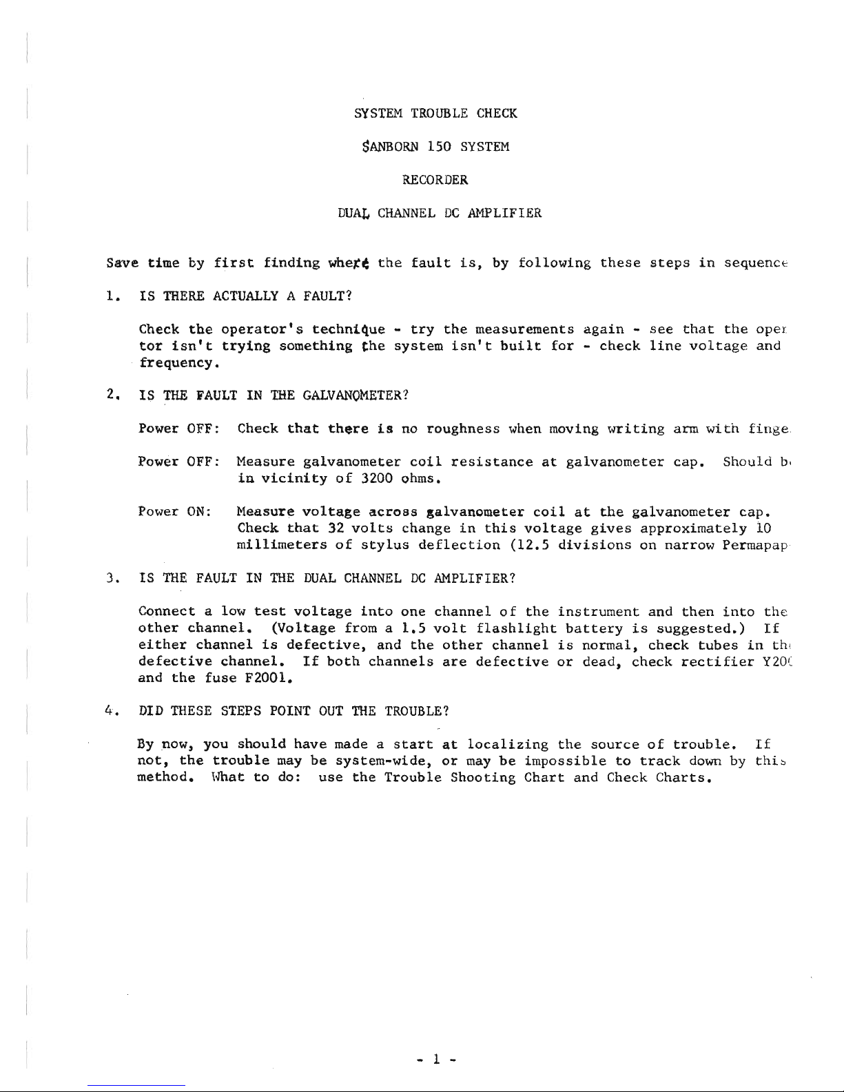
Save
time
by
first
finding
whet~
the
fault
is,
by
following
these
steps
in
sequenct
1.
IS
THERE
ACTUALLYAFAULT?
Check
the
operator's
techni~ue
-
try
the
measurements
again
-
see
that
the
ope!
tor
isn't
trying
something
~he
system
isn't
built
for
-
check
line
voltage
and
frequency.
2.
IS
THE
FAULT
IN
THE
GALVANOMETER?
Power OFF: Check
that
there
is
no
roughness
when moving
writing
arm
with
finge
Power OFF: Measure
galvanometer
coil
resistance
at
galvanometer
cap.
Should
b.
in
vicinity
of
3200 ohms.
Power
ON:
Measure
voltage
across
galvanometer
coil
at
the
galvanometer
cap.
Check
that
32
volts
change
in
this
voltage
gives
approximately
10
millimeters
of
stylus
deflection
(12.5
divisions
on
narrow
Permapap
3.
IS
THE
FAULT
IN
THE
DUAL
CHANNELDCAMPLIFIER?
Connect
a low
test
voltage
into
one
channel
of
the
instrument
and
then
into
the
other
channel.
(Voltage
from a
1.5
volt
flashlight
battery
is
suggested.)
If
either
channel
is
defective,
and
the
other
channel
is
normal,
check
tubes
in
th;
defective
channel.
If
both
channels
are
defective
or
dead,
check
rectifier
Y20C
and
the
fuse
F200l.
4.
DID
THESE
STEPS POINT
OUT
THE
TROUBLE?
By
now, you
should
have
made a
start
at
localizing
the
source
of
trouble.
If
not,
the
trouble
may
be
system-wide,
or
may
be
impossible
to
track
down
by
thi~
method.
\~at
to
do:
use
the
Trouble
Shooting
Chart
and Check
Charts.
- 1 -
Page 13

TROUBLE
SHOOTING
CHART
SANBORN
DUAL
CHANNELDCAMPLIFIER
MODEL
150-2000
This
chart
assumes
that
the
fault
has
been
traced
to
the
Dual Channel
DC
Amplifier.
SYMPTOM
Fuse
blows
each
time
instrument
turned
on.
Does
not
work;
tubes
do
not
light
Tubes
light,
but
no
oper-
ation
all
channels
No
,operation
one
channel
only,
other
channel
normal
.'.,.'hO
POSITION
control
will
not
move
stylus
over
entire
recording
channel
POSSIBLE
CAUSE
Defective
tube
Defective
condenser
Defective
transformer
Wrong
size
fuse
Blown
fuse
Loose
connectors
Defective
tube
Loose
connectors
Defective
tube
Loose
connector
Open
resistor
Defective
tube
Defective
condenser
Matched
resistor
pairs
out
of
tolerance
No
negative
bias
voltage
- 2 -
CHECK
Check V200l
Check
plug-in
condensers
C2006, C2007,
also
C200l
Check
T200l,
T2002
Must
be
1.25ASlo-Blo
Check
F200l
Check
that
power
connectors
P2002,
P2Q03
at
chassis
top
and
rear
are
firmly
in
plaCE
Check V200l
Check
that
signal
circuit
connectors
into
J2004
and
J2005
are
firmly
in
place
Check
tubes
in
defective
channel
Check
that
signal
circuit
co
nector
into
J2004
or
J2005
is
firmly
in
place
Check R200l
or
R2002, R20l0,
R2011
Check
tubes
in
defective
channel(s),
including
recti-
fier
V200l
Check
C20n
Check
matched
resistors
Page 14

I r
I
SYMPTOM
Stylus
stays
at
one
side
of
recording
channel
while
instrument
on
Erratic
stylus
motion
Low
sensitivity
Non-linear
POSSIBLE
CAUSE
Defective
tube
Leaky
condenser
Signal
overload
Intermittent
tube
Intermittent
rectifier
Loose
tube,
plug-in,
or
connector
Erratic
signal
Intermittent
circuit
element
Defective
tube
Improper
operation
Defective
tube
No
negative
bias
voltage
Mica
condenser
Low1ine
vo1tage
CHECK
Check
tubes
in
defective
channel(s)
Check
all
mica
condensers
If
stylus
returns
to
normal
with
ATTENUATORatOFF,
trouble
probably
coming
in
from
outside
the
instrument
Check
all
tubes
Check Y2001
Press
in
tightly
Check
signal
with
meter
and
oscilloscope
Check
with
meter
and
oscil-
loscope
for
intermittent
circuit
element
Check
all
tubes
Check
operating
technique
Check
all
tubes
Check Y2001, R2003, C2007A,
Check
mica
condensers
-
lea
age
across
or
through
them
can
alter
grid
bias
Check
that
line
voltage
is
within
limits
Defective
circuit
element,
Quick
check:
measure
for
giving
incorrect
circuit
approximately
1130
volts
at
voltages
6V6
grids
for
quick
check
c
proper
operating
voltages
Signal
- 3 -
Signal
having
high-frequenc
components
or
fast
pulses
n
not
show
on
the
recording,
but
still
drive
tubes
into
non-linear
region
Page 15

I I
SYMPTOM
Drift
Unsatisfactory
frequency
or
transient
(overshoot)
response,
or
cannot
ad-
just
damping
control(s)
POSSIBLE
CAUSE
Drifting
tube
May
be
drift
of
Perma-
paper
Drifting
signal
Line
voltage
or
fre-
quency
Inadequate
warmup
Drift
in
high-frequency
signal
component
Defective
tube
Improper
adjustment
Leakage
CHECK
Check
all
tubes
See
Recorder
Trouble
Shootin
Chart
Check
with
meter
and
oscillo
scope.
See
if
baseline
dril
with
ATTENUATORatOFF
Drifting
widely
or
outside
limits
can
cause
drift.
ChE
with
meter
Warm
up
at
least
the
stated
five
minutes
required
High-frequency
components
~a.
overload
the
grids
and
still
not
show
on
the
record
as
a
signal.
This
causes
a
non-
linearity,
which
can
appear
as
a
drift
if
the
high-fre-
quency
component
drifts.
Che<
with
meter
and
oscilloscope
Check
all
tubes
Re-adjust
Leakage
across
(or
through)
R2009-C2004
or
R2023-C2010.
If
dirty,
clean
with
carbon
tetrachloride
or
equivalent
Unsatisfactory
control
of
trace
density
See
the
Recorder
Trouble
Shooting
Chart
Noise,
microphonics,
or
hum
Defective
tube
Defective
component
Noisy
signal
Loose
input
plug
or
con-
nector
Open
shield
connection,
or
ground
loop
- 4 -
Check
all
tubes
Check
circuit
with
oscillo-
scope
to
find
source
of
inte:
ference
Check
signal
with
oscillosCOf
See
if
baseline
becomes
clear
with
ATTENUATORatOFF.
Plug
in
firmly
Check
input
circuit
cabling
Page 16

Quick
check:
Foraquick
check
on
operation,
set
POSITION
to
mid-scale
and
measure
from
grid
(terminalS)
to
ground
of
each
6V6
stage.
Should
be
appro
xi
mately
~130
volts.
to
indicate
normal
operation
of
entire
channel.
(Test
at
115
volt
line.)
Then
measure
from
terminalS
of
one
6V6
to
terminalS
of
the
other
6V6
in
the
same
channel;
should
not
be
more
than
a few
volts,
to
show
normal
operation.
PERIODIC
MAINTENANCE
SANBORN
DUAL
CHANNELDCAMPLIFIER
MODEL
150-2000
This
is
recommended
every
500
hours
of
operation,
or
every3to6months,
as
deter-
mined
by
experience.
1.
Replace
the
6V6GT
tubes
in
each
channel
- V2003, V2004, V2006, V2007. Use a
com-
mercial
tube
replacement,
or
use
Sanborn
replacement
no.
68A-4.
2.
Replace
the
5R4GY
tube
in
the
power
supply
- V2001. Use a
commercial
tube
repla(
ment,
or
use
Sanborn
replacement
no.
68A-43.
3.
Inspect
above-chassis
for
loose
tube,
controls,
plug-in
components,
and
connector
4.
Inspect
below-chassis
for
loose
resistors,
condensers,
terminal
boards,
etc.
5.
Look
for
evidence
of
overheated
components -
check
visually
and
by
smell
for
burr.
insulation,
transformers,
resistors,
condensers,
etc.
6.
Look
for
frayed
or
burned-away
insulation.
7.
Check
for
dents,
panel
scratches,
corrosion,
and
other
mechanical
abuse.
8.
Blowout
dust
and
dirt
with
an
air
hose.
9.
Go
through
the
steps
of
the
Check
Chart.
- 5 -
Page 17

CHECK
CHARt
1.
Warm
up Dual Channel
DC
Amplifier
at
least
five
minutes.
Line
voltage
at
115
volts.
Perform
following
tests
on
each
channel
of
the
instrument.
2.
Check
that
POSITION
control
will
move
stylus
across
entire
recording
channel.
Set
stylus
20
divisions
above
bottom
of
chart.
3.
Insert
signal
from
1.5
volt
flashlight
battery
and
series
switch.
Set
RANGE
swit
toIVOLT/CM
and
GAIN
control
full
right.
Check
for
at
least
17
mm.
stylus
deflf
tion
(21
divisions
with
narrow-channel
Permapaper).
Set
GAIN
for
15
divisions
deflection.
4.
Intermittently
operate
switch
and
adjust
DAMPING
control
for
best
possible
squar
wave
on
the
recording.
Leading
edge
of
square
wave
should
have
fast
rise,
with
no
overshoot.
5.
Insert
signal
from
audio
oscillator,
with
Dual Channel
DC
Amplifier
channel
set
to
10
divisions
peak-to-peak
recording.
Response
should
be
as
shown
on
characte
istic
curve
in
Instruction
Manual.
- 6 -
Page 18

Ii
I
I
II
II
I
11
II
Ii
II
~
I I
I
Ii
~
I
I
I
~
I
[
~
II
II
j
VOLTAGE AND RESISTANCE CHART
SANBORN
DUAL CHANNEL DC AMPLIFIER
MODEL 150-2000
i
1
!
I
,
TUBE
1 2 3
I
4 5 6
7 8 9
..
\12001
30K*
3.5K
3.5K
30K*
(4to6)
(6to4)
+38SV
800VAC
800VAC
+385V
V2002
700K
1.6M
3K
850K
1.6M
2.9VAC
2.9VAC
+130V
.22V
-3.5V
+130V
.22V
V2003
3.4VAC
90K*
90K*
1M
4SK*
6K
3.7VAC
3.1VAC
3.4VAC
+360V
+360V
+130V
..
V2004
. 100K*
lOOK*
1.2M
4SK*
6K
3.5VAC
3.9VAC
3.9VAC
3.4VAC
+360V
+360V
+130V
._--
V200S
1M
1.4M
3K
1M
1.4M
2VAC
2.9VAC
2.9VAC
+130V
.12V
-3.5V
+130V
.12V
---
V2006
4SK lOOK·
100K*
l.3M
4SK*
6K
3.4VAC
3.6VAC
3.6VAC
2VAC
3.4VAC
+360V
+360V
+130V
V2007
4SK
100K*
100K*
1.4M
4SK*
6K
3.4VAC
3.2VAC
3.2VAC
3.4VAC
+360V
+360V
+130V
--
_.
Readings
taken
with H. P. Model 4
lOB
VTVM.
A
1.5K
30W
resistor
across
pins
3-4,
5-4,
6-7,
8-7ofjack
2001tosimulate
galvanometers.
VOLTAGE READINGS
POWER
ON
NO
SIGNAL
ATTENUATOR
OFF
POSITION
CENTER
DAMPING CENTER
MEASURE FROM EACH TUBE SOCKET TERMINAL TO GROUND
RESISTANCE READINGS:
POWER
OFF
NO
SIGNAL
ATTENUATOR
OFF
POSITION
FULL
CLOCKWISE
DAMPING
FULL
COUNTERCLOCKWISE
MEASURE EACH TUBE SOCKET TERMINAL TO GROUND
·CHARGING CAPACITOR _ 7 _
Page 19

SANBORN DUAL CHANNEL
DC
AMPUFIER
MODEL
150-2000
Gi
C2008
r
~
H2019
~
G-I
H2021
ro
G-1
H2022
H:)
G1
C2009
te
G-fH2020
f-E).
G-i
H2018
t--0
-~-
__
9\
I
\
.' II
\
i
(
\
I
1
)
I
I
~I
I
~I
I
0
~I
....
,
1
0
1
I
....
I
I
I
I
I
I
I
I,
\
I
I
I
\
I
i
\
I
,
I
I
I
J
\_--
I
-<5--
<b
E2002
E2002
~
~
E2003
BOTTOM VIEW OF CHASSIS
G--1
H2016
t-0
G--i
H2015
r-e
G--1
H2014
l-e
G---l
H2013
f-8
G-1
H2012
t-0
Q---+
H2004
t-{)
G--i
R2006
~
0-{
C2003
~
~
R2008
~
G--l
H2007
r-E)
!~
C2002
~
E2003
COMPONENT LOCATION ON RESISTOR BOARDS
_ 8 -
Page 20

-
NOTES
. roond.
I +Denoles
ChassiS
0
81W
resistors
2Al20,10,2,
RW2
'os
..elIas R2009, R2008,
R
2004,
R2007,
R2022
R2018,R202I.a
or.5%lol.rallOt•.
Rnl.tar.
R~~~:"'~~ltIOfl.
R2037
or.
'Y.
C20048C2010
or.
5 •
capOCllo".
measured
:::hY~~I:;ct
to
etalile
qraund
---.
(.lI)u
',.
e
Ie
\;.
..
\
.~_
..
I?
2003
P2004,
p2005,a
P2002
J2001
~\
~
J2006 a
J2oo7
J2003
°
()
o
III~O
0:
000
0d
,'0
J2OO2,J2004,8 J2005
Stylus
T.mp.
R2037
SO
K
RANGE
VOLTs/eM.
Golv•B'-
,
Golv
'B'~
,
Gel.
'A'-
•
Golv
·A·
...
•
elv 'A'
C.T.
'
Gelv
'B'
CT.
:
10V
AC
60'1J
{I"
S
ylus
: B:Heof :
Stylus A Heat •
St/tlS
'"'.eat
Convnon
~
-unr.e 's· Input
 Loading...