

Page 1

HP Chromebook (model numbers 14-ak000
through 14-ak099)
HP Chromebook 14 G4
Maintenance and Service Guide
IMPORTANT! This document is intended for
HP authorized service providers only.
Page 2

© Copyright 2015 HP Development Company,
L.P.
Android is a U.S. registered trademark of
Android Corporation. Bluetooth is a trademark
owned by its proprietor and used by HP under
license. NVIDIA is a trademark of NVIDIA
Corporation in the U.S. and other countries. SD
Logo is a trademark of its proprietor.
The information contained herein is subject to
change without notice. The only warranties for
HP products and services are set forth in the
express warranty statements accompanying
such products and services. Nothing herein
should be construed as constituting an
additional warranty. HP shall not be liable for
technical or editorial errors or omissions
contained herein.
First Edition: September 2015
Document Part Number: 828939-001
Product notice
This user guide describes features that are
common to most models. Some features may
not be available on your computer.
Software terms
By installing, copying, downloading, or
otherwise using any software product
preinstalled on this computer, you agree to be
bound by the terms of the HP End User License
Agreement (EULA). If you do not accept these
license terms, your sole remedy is to return the
entire unused product (hardware and software)
within 14 days for a full refund subject to the
refund policy of your seller.
For any further information or to request a full
refund of the price of the computer, please
contact your seller.
Page 3

Safety warning notice
WARNING! To reduce the possibility of heat-related injuries or of overheating the device, do not place
the device directly on your lap or obstruct the device air vents. Use the device only on a hard, at surface. Do
not allow another hard surface, such as an adjoining optional printer, or a soft surface, such as pillows or rugs
or clothing, to block airow. Also, do not allow the AC adapter to contact the skin or a soft surface, such as
pillows or rugs or clothing, during operation. The device and the AC adapter comply with the user-accessible
surface temperature limits dened by the International Standard for Safety of Information Technology
Equipment (IEC 60950).
iii
Page 4

iv Safety warning notice
Page 5

Table of contents
1 Product description ....................................................................................................................................... 1
2 External component identication .................................................................................................................. 3
Display .................................................................................................................................................................... 3
Left side ................................................................................................................................................................. 4
Right side ............................................................................................................................................................... 5
Top .......................................................................................................................................................................... 6
TouchPad ............................................................................................................................................. 6
Buttons ................................................................................................................................................ 7
Bottom ................................................................................................................................................................... 8
Labels ..................................................................................................................................................................... 9
3 Illustrated parts catalog .............................................................................................................................. 10
Computer major components .............................................................................................................................. 10
Display assembly subcomponents ...................................................................................................................... 14
Rubber Kit ............................................................................................................................................................ 16
Miscellaneous parts ............................................................................................................................................. 16
4 Removal and replacement preliminary requirements ..................................................................................... 18
Tools required ...................................................................................................................................................... 18
Service considerations ......................................................................................................................................... 18
Plastic parts ....................................................................................................................................... 18
Cables and connectors ...................................................................................................................... 19
Drive handling ................................................................................................................................... 19
Grounding guidelines ........................................................................................................................................... 19
Electrostatic discharge damage ........................................................................................................ 19
Packaging and transporting guidelines .......................................................................... 21
Workstation guidelines ................................................................................ 21
5 Removal and replacement procedures for Authorized Service Provider parts ................................................... 23
Component replacement procedures .................................................................................................................. 23
Keyboard/top cover ........................................................................................................................... 23
TouchPad ........................................................................................................................................... 27
Power connector cable ...................................................................................................................... 29
USB board .......................................................................................................................................... 30
WLAN/Bluetooth combo card ............................................................................................................ 31
v
Page 6

Heat sink ............................................................................................................................................ 33
Display assembly ............................................................................................................................... 35
Battery ............................................................................................................................................... 42
Speakers ............................................................................................................................................ 44
System board .................................................................................................................................... 45
6 Specications .............................................................................................................................................. 47
7 Using HP PC Hardware Diagnostics (UEFI) ....................................................................................................... 48
Downloading HP PC Hardware Diagnostics (UEFI) to a USB device .................................................................... 48
8 Power cord set requirements ........................................................................................................................ 50
Requirements for all countries ............................................................................................................................ 50
Requirements for specic countries and regions ................................................................................................ 50
9 Statement of memory volatility .................................................................................................................... 52
Nonvolatile memory usage ................................................................................................................................. 56
Questions and answers ....................................................................................................................................... 58
Using HP Sure Start (select models only) ............................................................................................................ 59
10 Recycling .................................................................................................................................................. 60
Index ............................................................................................................................................................. 61
vi
Page 7

1 Product description
Category Description
Product Name HP Chromebook (model numbers 14-ak000 through 14-ak099)
HP Chromebook 14 G4
Processor Intel Celeron N2940 (1.83GHz, turbo up to 2.25GHz), 1333MHz/1MB L2, Quad SDP4.5W, BGA
Intel Celeron N2840 (2.16GHz, turbo up to 2.58GHz), 1333MHz/1MB L2, Dual SDP4.5W, BGA
Chipset Integrated SoC processor controller hub (PCH) for use on all computer models
Graphics Internal Graphics: Intel HD graphics
Support for HD decode, DX11, and HDMI
Panel Non-touch
14.0-in, high-denition (HD), WLED, anti-glare (1366×768), at (3.6 mm), SVA, 220 nits typical
brightness
14.0-in full high-denition (FHD), WLED, anti-glare (1920x1080), slim (3.0 mm), UWVA, 220 nits,
eDP, 220 nits typical brightness
* FHD panel requires N2940 processor and 4G memory.
Memory Onboard system memory
Supports up to 4096-MB maximum on-board system memory
DDR3L-1600 single channel support (DDR3L-1600 downgrade to DDR3L-1333) (for 2 GB memory)
DDR3L-1600 dual channel support (DDR3L-1600 downgrade to DDR3L-1333) (for 4 GB memory)
Storage Supports 16- and 32-GB embedded MultiMedia Controller (eMMC)
Audio and video HP TrueVision HD slim webcam, 1280×720 by 30 frames per second; xed (no tilt), with activity
LED
Single digital microphone with appropriate echo-cancellation, noise-suppression software
Two speakers
HD audio
Wireless Integrated wireless local area network (WLAN) options with dual antennas
Intel Dual Band Wireless-AC 7260 802.11 ac 2x2 WiFi + BT 4.0 Combo Adapter
Intel Dual Band Wireless-N 7260AN 802.11 a/b/g/n 2x2 WiFi + BT 4.0 combo
External media cards HP Multi-Format Digital Media Card Reader
Supports micro SD/SDHC/SDXC up to UHS-I
Push-Push Insertion/Removal
Ports AC Smart Pin adapter plug (4.5 mm barrel)
Headphone/microphone combo jack
HDMI v1.4b supporting up to 1920×1080 @ 60Hz
USB 3.0 port (1)
1
Page 8

Category Description
USB 2.0 ports (2)
Keyboard/pointing devices Full-sized, textured, island-style, Google keyboard (black) for use only on HP Chromebook 14 G4
Full-sized, textured, island-style, Google keyboard (white) for use only on HP Chromebook 14
Touchpad requirements:
Multitouch gestures enabled
Taps enabled as default
Power requirements Battery
Support for a 3-cell, 37-WHr battery
AC adapters
65-W, EM (for India and the People’s Republic of China)
45-W AC adapter (not for India or the People’s Republic of China)
1.0 meter power cord
Operating system Preinstalled: Google Chrome operating system
Serviceability End user replaceable part: AC adapter
2 Chapter 1 Product description
Page 9

2 External component identication
Display
Component Description
(1) Internal display switch Turns o the display and initiates Sleep if the display is closed while
the power is on.
NOTE: The internal display switch is not visible from the outside of
the computer.
(2) WLAN antennas* Send and receive wireless signals to communicate with wireless local
area networks (WLANs).
NOTE: The position of the WLAN antennas may dier, depending
on model.
(3) Internal microphone Records sound.
(4) Webcam Records video, captures still photographs, and allows video
conferences and online chat by means of streaming video.
(5) Webcam light On: The webcam is in use.
*The antennas are not visible from the outside of the computer. For optimal transmission, keep the areas immediately around the
antennas free from obstructions. For wireless regulatory notices, see the section of the Regulatory, Safety, and Environmental Notices
that applies to your country or region.
Display 3
Page 10
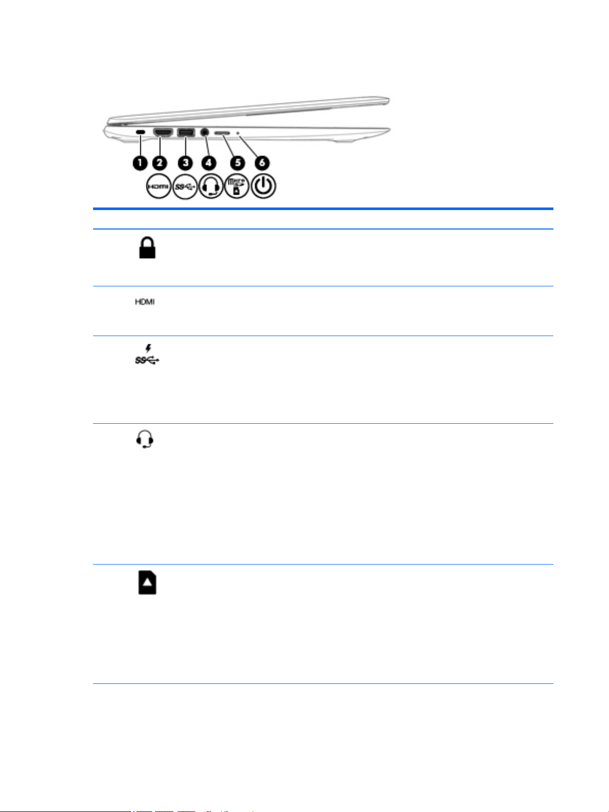
Left side
Component Description
(1) Security cable slot Attaches an optional security cable to the computer.
(2) HDMI port Connects an optional video or audio device, such as a high-
(3) USB 3.0 charging (powered) port Connects an optional USB device, such as a keyboard, mouse,
NOTE: The security cable is designed to act as a deterrent,
but it may not prevent the computer from being mishandled
or stolen.
denition television, any compatible digital or audio
component, or a high-speed High-Denition Multimedia
Interface (HDMI) device.
external drive, printer, scanner or USB hub. Standard USB
ports will not charge all USB devices or will charge using a low
current. Some USB devices require power and require you to
use a powered port.
NOTE: USB charging ports can also charge select cell phones
and MP3 players, even when the computer is o.
(4) Audio-out (headphone)/Audio-in (microphone)
jack
(5) Micro memory card reader Reads optional memory cards that store, manage, share, or
(6) Power light
Connects optional powered stereo speakers, headphones,
earbuds, a headset, or a television audio cable. Also connects
an optional headset microphone. This jack does not support
optional microphone-only devices.
WARNING! To reduce the risk of personal injury, adjust the
volume before putting on headphones, earbuds, or a headset.
NOTE: When a device is connected to the jack, the computer
speakers are disabled.
NOTE: Be sure that the device cable has 4-conductor
connector that supports both audio-out (headphone) and
audio-in (microphone).
access information.
To insert a card:
▲
Hold the card label-side up, with connectors facing the
slot, insert the card into the slot, and then push in on the
card until it is rmly seated.
To remove a card:
▲
Press in on the card it until it pops out.
●
White: Computer is on.
●
Blinking white: Computer is in Sleep mode.
4 Chapter 2 External component identication
Page 11

Component Description
Right side
Component Description
(1) USB 2.0 ports Connect optional USB devices, such as a keyboard, mouse,
●
O: The computer is o.
external drive, printer, scanner or USB hub.
(2) AC adapter light
(3) Power connector Connects an AC adapter.
●
White: The AC adapter is connected and the battery is
charged.
●
Amber: The AC adapter is connected and the battery is
charging.
●
O: The computer is using battery power.
Right side 5
Page 12
Top
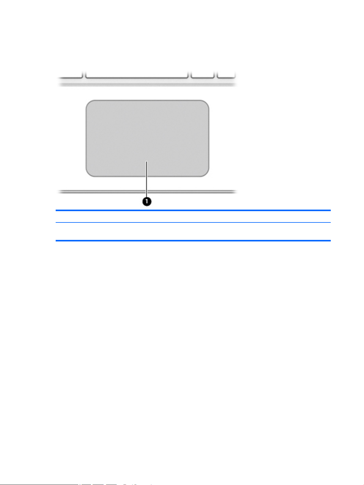
TouchPad
Component Description
(1) TouchPad zone Moves the on-screen pointer and selects or activates items on
the screen.
6 Chapter 2 External component identication
Page 13

Buttons
Component Description
(1) Power button
●
When the computer is o, press the button to turn on the
computer.
●
When the computer is in the Sleep state, press the button
briey to exit Sleep.
●
When the computer is on and you want to lock the screen,
press the power button until you see the sign-in screen
appear. Pressing the power button during screen-lock
mode turns o the computer.
●
When the computer is on and you want to turn it o, press
and hold the power
Top 7
Page 14

Bottom
Component Description
(1) Speakers (2) Produce sound.
8 Chapter 2 External component identication
Page 15

Labels
The labels axed to the computer provide information you may need when you troubleshoot system
problems or travel internationally with the computer.
IMPORTANT: All labels described in this section will be axed to the bottom of the computer.
NOTE: Your label may look slightly dierent from the illustration in this section.
●
Service label—Provides important information, including the following:
Component
(1) Model name (select products only)
(2) Product number
(3) Serial number
(4) Warranty period
Have this information available when you contact support.
●
Regulatory label—Provides regulatory information about the computer.
●
Wireless certication label or labels—Provide information about optional wireless devices and the
approval markings of some of the countries or regions in which the devices have been approved for use.
If your computer model includes one or more wireless devices, one or more certication labels are
included with your computer. You may need this information when traveling internationally.
Labels 9
Page 16

3 Illustrated parts catalog
NOTE: HP continually improves and changes product parts. For complete and current information on
supported parts for your computer, go to http://partsurfer.hp.com, select your country or region, and then
follow the on-screen instructions.
NOTE: Details about your computer, including model, serial number, product key, and length of warranty,
are on the service tag at the bottom of your computer. See Labels on page 9 for details.
Computer major components
10 Chapter 3 Illustrated parts catalog
Page 17

Item Component Spare part number
(1) Display assembly: The display assembly is spared at the subcomponent level only. For display assembly spare part
information, see Display assembly subcomponents on page 14.
(2) TouchPad (includes gasket)
For use in HP Chromebook 14 G4 models 830874-001
For use in silver HP Chromebook models 830874-001
For use in blue HP Chromebook models 835047-001
For use in purple HP Chromebook models 835048-001
(3) Touchpad cable 830870-001
(4) Keyboard/top cover (includes keyboard cable):
HP Chromebook 14 G4 models in silver nish:
●
For use in Belgium 834913-A41
●
For use in Canada 834913-DB1
●
For use in the Czech Republic and Slovakia 834913-FL1
●
For use in Denmark, Finland, and Norway 834913-DH1
●
For use in France 834913-051
●
For use in Germany 834913-041
●
For use in India 834913-D61
●
For use in Israel 834913-BB1
●
For use in Italy 834913-061
●
For use in Japan 834913-291
●
For use in Latin America 834913-161
●
For use in the Netherlands 834913-B31
●
For use in Russia 834913-251
●
For use in Saudi Arabia 834913-171
●
For use in Spain 834913-071
●
For use in Switzerland 834913-BG1
HP Chromebook models with silver nish:
●
For use in Taiwan 834913-AB1
●
For use in Thailand 834913-281
●
For use in the United Kingdom and Singapore 834913-031
●
For use in the United States 834913-001
●
For use in Belgium 830878-A41
●
For use in Canada 830878-DB1
●
For use in Denmark, Finland, and Norway 830878-DH1
Computer major components 11
Page 18

Item Component Spare part number
HP Chromebook models with blue nish:
●
For use in France 830878-051
●
For use in Germany 830878-041
●
For use in Italy 830878-061
●
For use in the Netherlands 830878-B31
●
For use in Russia 830878-251
●
For use in Spain 830878-071
●
For use in Switzerland 830878-BG1
●
For use in the United Kingdom and Singapore 830878-031
●
For use in the United States for use only on HP Chromebook 14 PC 830878-001
●
For use in Belgium 830879-A41
●
For use in Canada 830879-DB1
●
For use in Denmark, Finland, and Norway 830879-DH1
●
For use in France 830879-051
●
For use in Germany 830879-041
●
For use in Italy 830879-061
HP Chromebook models with purple nish:
●
For use in the Netherlands 830879-B31
●
For use in Russia 830879-251
●
For use in Spain 830879-071
●
For use in Switzerland 830879-BG1
●
For use in the United Kingdom and Singapore 830879-031
●
For use in the United States 830879-001
●
For use in Belgium 830880-A41
●
For use in Canada 830880-DB1
●
For use in Denmark, Finland, and Norway 830880-DH1
●
For use in France 830880-051
●
For use in Germany 830880-041
●
For use in Italy 830880-061
●
For use in the Netherlands 830880-B31
●
For use in Russia 830880-251
●
For use in Spain 830880-071
●
For use in Switzerland 830880-BG1
●
For use in the United Kingdom and Singapore 830880-031
12 Chapter 3 Illustrated parts catalog
Page 19

Item Component Spare part number
(5) USB cable 830869-001
(6) Battery (3-cell, 37-WHr, 3.28-AHr, Li-ion) 816609-005
(7) Power connector cable 841638-001
(8) Speakers (includes left and right speakers and cables) 787723-001
(9) USB board (includes cable and double-sided adhesive): 830873-001
(10) Heat sink (includes alcohol pad, thermal tape, and thermal grease) 830871-001
(11) System board (includes alcohol pad, thermal tape, and thermal grease)
For use in all models:
For use in HP Chromebook 14 G4 models:
●
For use in the United States 830880-001
●
System board equipped with a Intel Celeron N2940 processor, 4.0-GB of system
memory, and 16-GB of eMMC primary storage
●
System board equipped with a Intel Celeron N2840 processor, 4.0-GB of system
memory, and 16-GB of eMMC primary storage
●
System board equipped with a Intel Celeron N2840 processor, 2.0-GB of system
memory, and 16-GB of eMMC primary storage
●
System board equipped with a Intel Celeron N2940 processor, 4.0-GB of system
memory, and 32-GB of eMMC primary storage
830019-001
830018-001
830017-001
839038-001
(12) WLAN module:
Intel Dual Band Wireless-AC 7260 802.11 ac 2x2 WiFi + BT 4.0 Combo Adapter 784645-005
Intel Dual Band Wireless-N 7260AN 802.11 a/b/g/n 2x2 WiFi + BT 4.0 combo adaptor 784647-005
(13) Base enclosure:
For use in HP Chromebook models:
For use in HP Chromebook 14 G4 models:
●
System board equipped with a Intel Celeron N2940 processor, 2.0-GB of system
memory, and 32-GB of eMMC primary storage
●
System board equipped with a Intel Celeron N2940 processor, 2.0-GB of system
memory, and 16-GB of eMMC primary storage
●
System board equipped with a Intel Celeron N2840 processor, 4.0-GB of system
memory, and 32-GB of eMMC primary storage
●
System board equipped with a Intel Celeron N2840 processor, 2.0-GB of system
memory, and 32-GB of eMMC primary storage
●
Silver 830862-001
●
Blue 830863-001
●
Purple 830864-001
●
Silver 834906-001
839037-001
839036-001
839035-001
839034-001
Computer major components 13
Page 20

Display assembly subcomponents
Item Description Spare part number
(1) Display bezel (includes Mylar)
For use in HP Chromebook 14 G4 models:
For use in HP Chromebook models:
(2) Webcam/microphone module (includes bezel Mylar)
For use in HP Chromebook 14 G4 models 834912-001
For use in HP Chromebook models 830877-001
(3) Display panel (raw) (includes bezel Mylar)
●
Silver 834907-001
●
Silver 830865-001
●
Blue 830866-001
●
Purple 830867-001
14 Chapter 3 Illustrated parts catalog
Page 21

Item Description Spare part number
For use in models with HD displays 830015-001
For use in models with FHD displays 830016-001
Display Hinge Kit for in HP Chromebook 14 G4 models 834909-001
Display Hinge Kit for in HP Chromebook models 830872-001
(4a) Left hinge
(4b) Right hinge
(5) Antenna cable (includes bezel Mylar)
For use in HP Chromebook 14 G4 models 834904-001
For use in HP Chromebook models 830858-001
(6) Display panel cable (includes bezel Mylar)
For use in HP Chromebook 14 G4 models with HD displays 834908-001
For use in HP Chromebook 14 G4 models with FHD displays 841682-001
For use in HP Chromebook models with HD displays 830868-001
For use in HP Chromebook models with FHD displays 841536-001
(7) Display rear cover (includes bezel Mylar)
For use in HP Chomebook 14 G4 models:
For use in HP Chomebook models:
●
Silver 834905-001
●
Silver 830859-001
●
Blue 830860-001
●
Purple 830861-001
Display assembly subcomponents 15
Page 22

Rubber Kit
Item Description Spare part number
Rubber Kit for use in HP Chromebook 14 G4 models 834911-001
Rubber Kit for use in HP Chromebook models 830875-001
(1) Oval foot/screw covers
(2) Small foot/screw cover
(3) Large foot/screw cover
Miscellaneous parts
Component Spare part number
AC adapter
65-W HP Smart AC adapter (non-PFC, EM, 4.5-mm) for use on all computer models 714657-001
45-W HP Smart AC adapter (non-PFC, RC, 4.5-mm) for use on all computer models 741727-001
Power cord (3-pin, 1.0-meter, black):
For use in Australia for use on all computer models 755530-011
For use in Denmark for use on all computer models 755530-081
For use in Europe for use on all computer models 755530-021
For use in India for use on all computer models 755530-D61
For use in North America for use on all computer models 755530-001
For use in Switzerland for use on all computer models 755530-111
For use in the United Kingdom and Singapore for use on all computer models 755530-031
Rubber Kit (not illustrated, includes rubber feet/screw covers)
For use in Chromebook 14 G4 models: 834911-001
For use in Chromebook models: 830875-001
16 Chapter 3 Illustrated parts catalog
Page 23

Component Spare part number
Screw Kit 830876-001
HP HDMI to VGA Adapter 701943-001
RJ-45 to USB adapter 539614-001
Miscellaneous parts 17
Page 24

4 Removal and replacement preliminary
requirements
Tools required
You will need the following tools to complete the removal and replacement procedures:
●
Flat-bladed screw driver
●
Magnetic screw driver
●
Phillips P0 screw driver
Service considerations
The following sections include some of the considerations that you must keep in mind during disassembly
and assembly procedures.
NOTE: As you remove each subassembly from the computer, place the subassembly (and all accompanying
screws) away from the work area to prevent damage.
Plastic parts
CAUTION: Using excessive force during disassembly and reassembly can damage plastic parts. Use care
when handling the plastic parts. Apply pressure only at the points designated in the
maintenance instructions.
18 Chapter 4 Removal and replacement preliminary requirements
Page 25

Cables and connectors
CAUTION: When servicing the computer, be sure that cables are placed in their proper locations during the
reassembly process. Improper cable placement can damage the computer.
Cables must be handled with extreme care to avoid damage. Apply only the tension required to unseat or seat
the cables during removal and insertion. Handle cables by the connector whenever possible. In all cases, avoid
bending, twisting, or tearing cables. Be sure that cables are routed in such a way that they cannot be caught
or snagged by parts being removed or replaced. Handle ex cables with extreme care; these cables tear
easily.
Drive handling
CAUTION: Drives are fragile components that must be handled with care. To prevent damage to the
computer, damage to a drive, or loss of information, observe these precautions:
Before removing or inserting a drive, shut down the computer. If you are unsure whether the computer is o
or in Hibernation, turn the computer on, and then shut it down through the operating system.
Before handling a drive, be sure that you are discharged of static electricity. While handling a drive, avoid
touching the connector.
Before removing a diskette drive or optical drive, be sure that a diskette or disc is not in the drive and be sure
that the optical drive tray is closed.
Handle drives on surfaces covered with at least one inch of shock-proof foam.
Avoid dropping drives from any height onto any surface.
After removing drive, place it in a static-proof bag.
Avoid exposing a drive to products that have magnetic elds, such as monitors or speakers.
Avoid exposing a drive to temperature extremes or liquids.
If a drive must be mailed, place the drive in a bubble pack mailer or other suitable form of protective
packaging and label the package “FRAGILE.”
Grounding guidelines
Electrostatic discharge damage
Electronic components are sensitive to electrostatic discharge (ESD). Circuitry design and structure determine
the degree of sensitivity. Networks built into many integrated circuits provide some protection, but in many
cases, ESD contains enough power to alter device parameters or melt silicon junctions.
A discharge of static electricity from a nger or other conductor can destroy static-sensitive devices or
microcircuitry. Even if the spark is neither felt nor heard, damage may have occurred.
An electronic device exposed to ESD may not be aected at all and can work perfectly throughout a normal
cycle. Or the device may function normally for a while, then degrade in the internal layers, reducing its life
expectancy.
Grounding guidelines 19
Page 26

CAUTION: To prevent damage to the computer when you are removing or installing internal components,
observe these precautions:
Keep components in their electrostatic-safe containers until you are ready to install them.
Before touching an electronic component, discharge static electricity by using the guidelines described in this
section.
Avoid touching pins, leads, and circuitry. Handle electronic components as little as possible.
If you remove a component, place it in an electrostatic-safe container.
The following table shows how humidity aects the electrostatic voltage levels generated by
dierent activities.
CAUTION: A product can be degraded by as little as 700 V.
Typical electrostatic voltage levels
Relative humidity
Event 10% 40% 55%
Walking across carpet 35,000 V 15,000 V 7,500 V
Walking across vinyl oor 12,000 V 5,000 V 3,000 V
Motions of bench worker 6,000 V 800 V 400 V
Removing DIPS from plastic tube 2,000 V 700 V 400 V
Removing DIPS from vinyl tray 11,500 V 4,000 V 2,000 V
Removing DIPS from Styrofoam 14,500 V 5,000 V 3,500 V
Removing bubble pack from PCB 26,500 V 20,000 V 7,000 V
Packing PCBs in foam-lined box 21,000 V 11,000 V 5,000 V
20 Chapter 4 Removal and replacement preliminary requirements
Page 27

Packaging and transporting guidelines
Follow these grounding guidelines when packaging and transporting equipment:
●
To avoid hand contact, transport products in static-safe tubes, bags, or boxes.
●
Protect ESD-sensitive parts and assemblies with conductive or approved containers or packaging.
●
Keep ESD-sensitive parts in their containers until the parts arrive at static-free workstations.
●
Place items on a grounded surface before removing items from their containers.
●
Always be properly grounded when touching a component or assembly.
●
Store reusable ESD-sensitive parts from assemblies in protective packaging or nonconductive foam.
●
Use transporters and conveyors made of antistatic belts and roller bushings. Be sure that mechanized
equipment used for moving materials is wired to ground and that proper materials are selected to avoid
static charging. When grounding is not possible, use an ionizer to dissipate electric charges.
Workstation guidelines
Follow these grounding workstation guidelines:
●
Cover the workstation with approved static-shielding material.
●
Use a wrist strap connected to a properly grounded work surface and use properly grounded tools and
equipment.
●
Use conductive eld service tools, such as cutters, screw drivers, and vacuums.
●
When xtures must directly contact dissipative surfaces, use xtures made only of static-safe materials.
●
Keep the work area free of nonconductive materials, such as ordinary plastic assembly aids
and Styrofoam.
●
Handle ESD-sensitive components, parts, and assemblies by the case or PCM laminate. Handle these
items only at static-free workstations.
●
Avoid contact with pins, leads, or circuitry.
●
Turn o power and input signals before inserting or removing connectors or test equipment.
Grounding guidelines 21
Page 28

Equipment guidelines
Grounding equipment must include either a wrist strap or a foot strap at a grounded workstation.
●
When seated, wear a wrist strap connected to a grounded system. Wrist straps are exible straps with a
minimum of one megohm ±10% resistance in the ground cords. To provide proper ground, wear a strap
snugly against the skin at all times. On grounded mats with banana-plug connectors, use alligator clips
to connect a wrist strap.
●
When standing, use foot straps and a grounded oor mat. Foot straps (heel, toe, or boot straps) can be
used at standing workstations and are compatible with most types of shoes or boots. On conductive
oors or dissipative oor mats, use foot straps on both feet with a minimum of one megohm resistance
between the operator and ground. To be
The following grounding equipment is recommended to prevent electrostatic damage:
●
Antistatic tape
●
Antistatic smocks, aprons, and sleeve protectors
●
Conductive bins and other assembly or soldering aids
●
Nonconductive foam
●
Conductive computerop workstations with ground cords of one megohm resistance
●
Static-dissipative tables or oor mats with hard ties to the ground
●
Field service kits
eective, the conductive must be worn in contact with the skin.
●
Static awareness labels
●
Material-handling packages
●
Nonconductive plastic bags, tubes, or boxes
●
Metal tote boxes
●
Electrostatic voltage levels and protective materials
The following table lists the shielding protection provided by antistatic bags and oor mats.
Material Use Voltage protection level
Antistatic plastics Bags 1,500 V
Carbon-loaded plastic Floor mats 7,500 V
Metallized laminate Floor mats 5,000 V
22 Chapter 4 Removal and replacement preliminary requirements
Page 29

5 Removal and replacement procedures for
Authorized Service Provider parts
CAUTION: Components described in this chapter should only be accessed by an authorized service provider.
Accessing these parts can damage the computer or void the warranty.
NOTE: HP continually improves and changes product parts. For complete and current information on
supported parts for your computer, go to http://partsurfer.hp.com, select your country or region, and then
follow the on-screen instructions.
Component replacement procedures
There are as many as 48 screws that must be removed, replaced, and/or loosened when servicing the
computer. Make special note of each screw size and location during removal and replacement.
Keyboard/top cover
NOTE: The keyboard/top cover spare part kit includes the keyboard cable.
Description Spare part number Description Spare part number
Keyboard/top cover in silver nish for use only on HP Chromebook 14 G4 models:
For use in Belgium 834913-A41 For use in Latin America 834913-161
For use in Canada 834913-DB1 For use in the Netherlands 834913-B31
For use in the Czech Republic and
Slovakia
For use in Denmark, Finland,
and Norway
For use in France 834913-051 For use in Spain 834913-071
For use in Germany 834913-041 For use in Switzerland 834913-BG1
For use in India 834913-D61 For use in Taiwan 834913-AB1
For use in Israel 834913-BB1 For use in Thailand 834913-281
For use in Italy 834913-061 For use in the United Kingdom
For use in Japan 834913-291 For use in the United States 834913-001
Keyboard/top cover in silver nish for use only on HP Chromebook models:
For use in Belgium 830878-A41 For use in the Netherlands 830878-B31
For use in Canada 830878-DB1 For use in Russia 830878-251
For use in Denmark, Finland,
and Norway
834913-FL1 For use in Russia 834913-251
834913-DH1 For use in Saudi Arabia 834913-171
834913-031
and Singapore
830878-DH1 For use in Spain 830878-071
For use in France 830878-051 For use in Switzerland 830878-BG1
Component replacement procedures 23
Page 30

Description Spare part number Description Spare part number
For use in Germany 830878-041 For use in the United Kingdom
and Singapore
For use in Italy 830878-061 For use in the United States 830878-001
Keyboard/top cover in blue nish for use only on HP Chromebook models:
For use in Belgium 830879-A41 For use in the Netherlands 830879-B31
For use in Canada 830879-DB1 For use in Russia 830879-251
For use in Denmark, Finland,
and Norway
For use in France 830879-051 For use in Switzerland 830879-BG1
For use in Germany 830879-041 For use in the United Kingdom
For use in Italy 830879-061 For use in the United States 830879-001
Keyboard/top cover in purple nish for use only on HP Chromebook models:
For use in Belgium 830880-A41 For use in the Netherlands 830880-B31
For use in Canada 830880-DB1 For use in Russia 830880-251
For use in Denmark, Finland,
and Norway
For use in France 830880-051 For use in Switzerland 830880-BG1
830879-DH1 For use in Spain 830879-071
and Singapore
830880-DH1 For use in Spain 830880-071
830878-031
830879-031
For use in Germany 830880-041 For use in the United Kingdom
and Singapore
For use in Italy 830880-061 For use in the United States 830880-001
830880-031
Before removing the disassembling the computer, follow these steps:
1. Turn o the computer. If you are unsure whether the computer is o or in Hibernation, turn the
computer on, and then shut it down through the operating system.
2. Disconnect the power from the computer by unplugging the power cord from the computer.
3. Disconnect all external devices from the computer.
NOTE: When replacing the keyboard/top cover, be sure that the heat sink (see Heat sink on page 33) and
TouchPad (see TouchPad on page 27) are removed from the defective keyboard/top cover and installed on
the replacement keyboard/top cover.
Remove the keyboard/top cover:
1. Close the computer.
2. Position the computer upside down with the front toward you.
3. Remove the two larger rubber feet/screw covers (1).
4. Remove the two oval rubber feet/screw covers (2).
24 Chapter 5 Removal and replacement procedures for Authorized Service Provider parts
Page 31

5. Remove the middle smaller rubber foot/screw cover (3).
NOTE: The feet/screw covers are included in the Rubber Kit, spare part number 834911-001 for use
only on HP Chromebook 14 G4 models and 830875-001 for use only on HP Chromebook models.
6. Remove the 13 Phillips PM2.0×5.0 screws that secure the keyboard/top cover to the base enclosure.
7. Turn the computer right side up with the front toward you.
8. Open the computer as far as it will open.
9. Lift the front edge (1) of the keyboard/top cover until it separates from the front edge of the
base enclosure.
10. Lift the tape (2) that secures the keyboard cable.
Component replacement procedures 25
Page 32

11. Release the zero insertion force (ZIF) connector (3) to which the keyboard cable is attached, and then
disconnect the keyboard cable (4) from the system board.
12. Release the ZIF connector (5) to which the TouchPad cable is attached, and then disconnect the
TouchPad cable (6) from the system board.
13. Remove keyboard/top cover (7) by sliding it forward.
Reverse this procedure to install the keyboard/top cover.
26 Chapter 5 Removal and replacement procedures for Authorized Service Provider parts
Page 33

TouchPad
Before removing the TouchPad, follow these steps:
1. Turn o the computer. If you are unsure whether the computer is o or in Hibernation, turn the
2. Disconnect the power from the computer by unplugging the power cord from the computer.
3. Disconnect all external devices from the computer.
4. Remove the keyboard/top cover (see Keyboard/top cover on page 23).
Remove the TouchPad button board:
1. Position the keyboard/top cover upside down with the front toward you.
Description Spare part number
TouchPad for use in HP Chromebook 14 G4 models (includes gasket) 830874-001
TouchPad for use in silver HP Chromebook models (includes gasket) 830874-001
TouchPad for use in blue HP Chromebook models (includes gasket) 835047-001
TouchPad for use in purple HP Chromebook models (includes gasket) 835048-001
Touchpad cable 830870-001
computer on, and then shut it down through the operating system.
2. Detach the TouchPad cable (1) from the keyboard/top cover. (The TouchPad cable is attached to the
keyboard/top cover with double-sided adhesive.)
3. Remove the two Phillips PM2.0×2.0 broad head screws (2) that secure the TouchPad to the
keyboard/top cover.
4. Release the TouchPad (3) by pressing it through the opening in the keyboard/top cover.
Component replacement procedures 27
Page 34

5. Remove the TouchPad (4).
Reverse this procedure to install the TouchPad.
28 Chapter 5 Removal and replacement procedures for Authorized Service Provider parts
Page 35

Power connector cable
Description Spare part number
Power connector cable 841638-001
Before removing the power connector cable, follow these steps:
1. Turn o the computer. If you are unsure whether the computer is o or in Hibernation, turn the
computer on, and then shut it down through the operating system.
2. Disconnect the power from the computer by unplugging the power cord from the computer.
3. Disconnect all external devices from the computer.
4. Remove the keyboard/top cover (see Keyboard/top cover on page 23).
5. Disconnect the battery cable from the system board (see Battery on page 42).
Remove the power connector cable:
1. Disconnect the cable (1) from the system board.
2. Release the cable from the routing clips (2) built into the base enclosure.
3. Remove the power connector cable (3).
Reverse this procedure to install the power connector cable.
Component replacement procedures 29
Page 36

USB board
Description Spare part number
USB board 830873-001
USB board cable 830869-001
Before removing the USB board, follow these steps:
1. Turn o the computer. If you are unsure whether the computer is o or in Hibernation, turn the
2. Disconnect the power from the computer by unplugging the power cord from the computer.
3. Disconnect all external devices from the computer.
4. Remove the keyboard/top cover (see Keyboard/top cover on page 23).
5. Disconnect the battery cable from the system board (see Battery on page 42).
Remove the USB board:
1. Release the ZIF connector (1) to which the USB board ribbon cable is attached, and then disconnect the
2. Remove the two Philllips PM2.0×2.0 broad head screws (2) that secure the USB board to the
computer on, and then shut it down through the operating system.
cable from the USB board.
base enclosure.
3. Remove the USB board (3).
Reverse this procedure to install the USB board.
30 Chapter 5 Removal and replacement procedures for Authorized Service Provider parts
Page 37

WLAN/Bluetooth combo card
The computer uses a card that provides both WLAN and Bluetooth functionality.
Description Spare part number
Intel Dual Band Wireless-AC 7260 802.11 ac 2x2 WiFi + BT 4.0 Combo Adapter 784645-005
Intel Dual Band Wireless-N 7260AN 802.11 a/b/g/n 2x2 WiFi + BT 4.0 combo adaptor 784647-005
Before removing the WLAN module, follow these steps:
1. Turn o the computer. If you are unsure whether the computer is o or in Hibernation, turn the
computer on, and then shut it down through the operating system.
2. Disconnect the power from the computer by unplugging the power cord from the computer.
3. Disconnect all external devices from the computer.
4. Remove the keyboard/top cover (see Keyboard/top cover on page 23).
5. Disconnect the battery cable from the system board (see Battery on page 42).
Remove the WLAN module:
1. Disconnect the WLAN antenna cables (1) from the terminals on the WLAN module.
NOTE: The WLAN antenna cable labeled “1” connects to the WLAN module “Main” terminal labeled “1”.
The WLAN antenna cable labeled “2” connects to the WLAN module “Aux” terminal labeled “2”. If the
computer is equipped with an 802.11a/b/g/n WLAN module, the yellow WLAN antenna cable connects to
the middle terminal on the WLAN module.
2. Remove the Phillips PM2.0×4.0 screw (2) that secures the WLAN module to the computer. (The edge of
the module opposite the slot rises away from the computer.)
Component replacement procedures 31
Page 38

3. Remove the WLAN module (3) by pulling the module away from the slot at an angle.
NOTE: WLAN modules are designed with a notch to prevent incorrect insertion.
NOTE: If the WLAN antennas are not connected to the terminals on the WLAN module, the protective
sleeves must be installed on the antenna connectors, as shown in the following illustration.
Reverse this procedure to install the WLAN module.
32 Chapter 5 Removal and replacement procedures for Authorized Service Provider parts
Page 39

Heat sink
Before removing the heat sink, follow these steps:
1. Turn o the computer. If you are unsure whether the computer is o or in Hibernation, turn the
2. Disconnect the power from the computer by unplugging the power cord from the computer.
3. Disconnect all external devices from the computer.
4. Remove the keyboard/top cover (see Keyboard/top cover on page 23).
5. Disconnect the battery cable from the system board (see Battery on page 42).
Remove the heat sink:
1. Remove the two Phillips PM2.0×2.0 screws (1) that secure the heat sink to the system board.
Description Spare part number
Heat sink (includes alcohol pad, thermal tape, and thermal grease) 830871-001
computer on, and then shut it down through the operating system.
Component replacement procedures 33
Page 40

2. Remove the heat sink (2).
NOTE: The thermal material must be thoroughly cleaned from the surfaces of the system board and
the heat sink components each time the heat sink is removed. Thermal paste is used on the processor
(1) and the heat sink section (2) that services it.
Reverse this procedure to install the heat sink.
34 Chapter 5 Removal and replacement procedures for Authorized Service Provider parts
Page 41

Display assembly
Before removing the display assembly, follow these steps:
1. Turn o the computer. If you are unsure whether the computer is o or in Hibernation, turn the
computer on, and then shut it down through the operating system.
2. Disconnect the power from the computer by unplugging the power cord from the computer.
3. Disconnect all external devices from the computer.
4. Remove the keyboard/top cover (see Keyboard/top cover on page 23).
5. Disconnect the battery cable from the system board (see Battery on page 42).
Remove the display assembly:
1. Release the ZIF connector (1) to which the display panel cable is attached, and then disconnect the
display panel cable from the system board.
2. Disconnect the wireless antenna cables (2) from the WLAN terminals on the system board and WLAN
terminals on the WLAN module.
NOTE: The white WLAN antenna cable labeled “1/Main” connects to the system board “Main” terminal.
The black WLAN antenna cable labeled “2/Aux” connects to the system board “Aux” terminal.
3. Remove the two Phillips 2.0×4.0 screws (3) that secure the display assembly to the base enclosure.
4. Remove the display assembly (4).
5. If it is necessary to replace the display enclosure or any of the display assembly subcomponents:
a. Remove the two display bezel screw covers (1).
b. Remove the two Phillips PM2.0×2.0 broad head screws (2) that secure the display enclosure to the
display panel assembly.
Component replacement procedures 35
Page 42

c. Using a at plastic tool, separate the top edge of the display bezel from the enclosure (3), then the
left and right sides (4), and then the bottom (5). Remove the bezel from the display enclosure (6).
NOTE: When lifting the bezel, make sure the mylar between the bezel and panel does not pull
free from the panel.
The display bezel is available using the following spare part numbers:
●
834907-001–For use on HP Chromebook 14 G4 models
●
830865-001–For use on silver HP Chromebook models
●
830866-001–For use on blue HP Chromebook models
●
830867-001–For use on purple HP Chromebook models
6. If it is necessary to replace the webcam/microphone module:
a. Detach the webcam/microphone module (1) from the display enclosure. (The webcam/microphone
module is attached to the display enclosure with double-sided adhesive at two locations.)
36 Chapter 5 Removal and replacement procedures for Authorized Service Provider parts
Page 43

b. Disconnect the webcam/microphone module cable (2) from the webcam/microphone module.
c. Remove the webcam/microphone module.
The webcam/microphone module is available using spare part number 834912-001 for use on HP
Chromebook 14 G4 models or 830877-001 for use on HP Chromebook models.
7. If it is necessary to replace the display panel:
a. Remove the four Phillips PM2.0×3.0 screws (1) that secure the display panel to the
display enclosure.
CAUTION: Before turning the display panel upside down, make sure the work surface is clear of
tools, screws, and any other foreign objects. Failure to follow this caution can result in damage to
the display panel.
Component replacement procedures 37
Page 44

b. Lift the top edge of the display panel (2) and swing it up and forward until it rests upside down in
front of the display enclosure.
The raw display panel is available using spare part number 830015-001 for HD displays and
830016-001 for FHD displays.
c. Release the adhesive strip (1) that secures the display panel cable connector to the display panel.
d. Disconnect the display panel cable (2) from the display panel.
e. Remove the display panel (3).
8. If it is necessary to replace the display hinges:
38 Chapter 5 Removal and replacement procedures for Authorized Service Provider parts
Page 45

a. Remove the following screws that secure the display hinges and display hinge support brackets to
the display enclosure:
(1) Two Phillips PM2.0×3.0 screws that secure the display hinge brackets
(2) Four Phillips PM2.5×3.0 broad head screws that secure the display hinges
(3) Two Phillips PM2.0×2.0 screws that secure the display hinges
b. Remove the display hinges (4).
The display hinges are included in the Display Hinge Kit, spare part number 834909-001 for use on
HP Chromebook 14 G4 models or 830872-001 on HP Chromebook models.
9. If it is necessary to replace the display panel cable:
a. Disconnect the display panel cable from the webcam/microphone module (1).
b. Release the display panel cable from the retention clips (2) and channel built into the top, left, and
bottom edges of the display enclosure.
c. Remove the display panel cable (3).
The display panel cable is available using the following spare part numbers:
●
834908-001–For use on HP Chromebook 14 G4 models with HD displays
●
841682-001–For use on silver HP Chromebook models with FHD displays
●
830868-001–For use on blue HP Chromebook models with HD displays
●
841536-001–For use on purple HP Chromebook models with FHD displays
Component replacement procedures 39
Page 46

10. If it is necessary to replace the antenna cable:
a. Peel to remove the transceivers from the top of the display enclosure (1).
b. Release the cable from the retention clips (2) and channel built into the side of the
display enclosure.
c. Remove the antenna cable (3).
The antenna cable is available using spare part number 834904-001 for HP Chromebook 14 G4
models and 830858-001 for HP Chromebook models.
The display rear cover is available using the following spare part numbers:
40 Chapter 5 Removal and replacement procedures for Authorized Service Provider parts
Page 47

●
834905-001–For use on HP Chromebook 14 G4 models
●
830859-001–For use on silver HP Chromebook models
●
830860-001–For use on blue HP Chromebook models
●
830861-001–For use on purple HP Chromebook models
Reverse this procedure to reassemble and install the display assembly.
Component replacement procedures 41
Page 48

Battery
Description Spare part number
Battery, 3-cell, 37-WHr, 3.28-AHr, Li-ion 816609-005
Before removing the battery, follow these steps:
1. Turn o the computer. If you are unsure whether the computer is o or in Hibernation, turn the
computer on, and then shut it down through the operating system.
2. Disconnect the power from the computer by unplugging the power cord from the computer.
3. Disconnect all external devices from the computer.
4. Remove the keyboard/top cover (see Keyboard/top cover on page 23).
Remove the battery:
1. Disconnect the battery cable from the system board.
2. Remove the eight Phillips PM2.0×3.0 screws (1) that secure the battery to the base enclosure.
42 Chapter 5 Removal and replacement procedures for Authorized Service Provider parts
Page 49

3. Lift the battery from the computer (2).
Reverse this procedure to install the battery.
Component replacement procedures 43
Page 50

Speakers
Before removing the speakers, follow these steps:
1. Turn o the computer. If you are unsure whether the computer is o or in Hibernation, turn the
2. Disconnect the power from the computer by unplugging the power cord from the computer.
3. Disconnect all external devices from the computer.
4. Remove the keyboard/top cover (see Keyboard/top cover on page 23).
5. Remove the battery (see Battery on page 42).
Remove the speakers:
1. Disconnect the speaker cable (1) from the system board.
2. Disengage each speaker from the computer by using a tool to pry up near the tabs of each speaker (2).
3. Remove the tape (3), and then release the speaker cables from the routing clips (4) and channels built
Description Spare part number
Speakers (include left and right speakers and cables) 787723-001
computer on, and then shut it down through the operating system.
into the base enclosure.
4. Remove the speakers (5).
Reverse this procedure to install the speakers.
44 Chapter 5 Removal and replacement procedures for Authorized Service Provider parts
Page 51

System board
Description Spare part number
System board for use in all models (includes alcohol pad, thermal tape, and thermal grease):
Equipped with a Intel Celeron N2940 processor, 4.0-GB of system memory, and 16-GB of eMMC primary storage 830019-001
Equipped with a Intel Celeron N2840 processor, 4.0-GB of system memory, and 16-GB of eMMC primary storage 830018-001
Equipped with a Intel Celeron N2840 processor, 2.0-GB of system memory, and 16-GB of eMMC primary storage 830017-001
System board for use in HP Chromebook 14 G4 models (includes alcohol pad, thermal tape, and thermal grease):
Equipped with a Intel Celeron N2940 processor, 4.0-GB of system memory, and 32-GB of eMMC primary storage 839038-001
Equipped with a Intel Celeron N2940 processor, 2.0-GB of system memory, and 32-GB of eMMC primary storage 839037-001
Equipped with a Intel Celeron N2940 processor, 2.0-GB of system memory, and 16-GB of eMMC primary storage 839036-001
Equipped with a Intel Celeron N2840 processor, 4.0-GB of system memory, and 32-GB of eMMC primary storage 839035-001
Equipped with a Intel Celeron N2840 processor, 2.0-GB of system memory, and 32-GB of eMMC primary storage 839034-001
Before removing the system board, follow these steps:
1. Turn o the computer. If you are unsure whether the computer is o or in Hibernation, turn the
computer on, and then shut it down through the operating system.
2. Disconnect the power from the computer by unplugging the power cord from the computer.
3. Disconnect all external devices from the computer.
4. Remove the keyboard/top cover (see Keyboard/top cover on page 23).
5. Remove the battery (see Battery on page 42).
Remove the system board:
1. Disconnect the speaker cable (1) from the system board.
2. Release the ZIF connector (2) to which the display panel cable is attached, and then disconnect the
display panel cable from the system board.
3. Release the ZIF connector (3) to which the connector board cable is attached, and then disconnect the
connector board cable from the system board.
Component replacement procedures 45
Page 52

4. Disconnect the power connector cable (4) from the system board.
5. Remove the four Philllips PM2.0×2.0 screws (1) that secure the system board to the base enclosure.
6. Lift the right side of the system board (2) until it rests at an angle.
7. Remove the system board (3) by sliding it up and to the right at an angle.
Reverse this procedure to install the system board.
46 Chapter 5 Removal and replacement procedures for Authorized Service Provider parts
Page 53

6 Specications
Metric U.S.
Computer dimensions
Width 34.4 cm 13.5 in
Depth 24.0 cm 9.5 in
Height 1.8 cm 0.7 in
Weight 1.7 kg 3.8 lbs
Operating voltage and current: 19.5V dc @ 2.31 A – 45 W
NOTE: This product is designed for IT power systems in Norway with phase-to-phase voltage not exceeding 240 V rms.
NOTE: The device operating voltage and current can be found on the system regulatory label.
Temperature
Operating 5°C to 35°C 41°F to 95°F
Nonoperating ‑20°C to 60°C ‑4°F to 140°F
19.5V dc @ 3.33 A – 65 W
Relative humidity (noncondensing)
Operating 10% to 90%
Nonoperating 5% to 95%
Maximum altitude (unpressurized)
Operating ‑15 m to 3,048 m ‑50 ft to 10,000 ft
Nonoperating ‑15 m to 12,192 m ‑50 ft to 40,000 ft
NOTE: Applicable product safety standards specify thermal limits for plastic surfaces. The device operates well within this range of
temperatures.
47
Page 54

7 Using HP PC Hardware Diagnostics (UEFI)
HP PC Hardware Diagnostics is a Unied Extensible Firmware Interface (UEFI) that allows you to run diagnostic
tests to determine whether the computer hardware is functioning properly. The tool runs outside the
operating system so that it can isolate hardware failures from issues that are caused by the operating system
or other software components.
When HP PC Hardware Diagnostics (UEFI) detects a failure that requires hardware replacement, a 24-digit
Failure ID code is generated. This ID code can then be provided to support to help determine how to correct
the problem.
NOTE: To start diagnostics on a convertible computer, your computer must be in notebook mode and you
must use the keyboard attached.
To start HP PC Hardware Diagnostics (UEFI), follow these steps:
1. Turn on or restart the computer, and quickly press esc.
2. Press f2.
The BIOS searches three places for the diagnostic tools, in the following order:
a. Connected USB drive
NOTE: To download the HP PC Hardware Diagnostics (UEFI) tool to a USB drive, see Downloading
HP PC Hardware Diagnostics (UEFI) to a USB device on page 48.
b. Hard drive
c. BIOS
3. When the diagnostic tool opens, select the type of diagnostic test you want to run, and then follow the
on-screen instructions.
NOTE: If you need to stop a diagnostic test, press esc.
Downloading HP PC Hardware Diagnostics (UEFI) to a USB device
NOTE: The HP PC Hardware Diagnostics (UEFI) download instructions are provided in English only, and you
must use a Windows computer to download and create the HP UEFI support environment because only .exe
les are oered.
There are two options to download HP PC Hardware Diagnostics to a USB device.
Download the latest UEFI version
1. Go to http://www.hp.com/go/techcenter/pcdiags. The HP PC Diagnostics home page is displayed.
2. In the HP PC Hardware Diagnostics section, click the Download link, and then select Run.
Download any version of UEFI for a specic product
1. Go to http://www.hp.com/support, and then select your country. The HP Support page is displayed.
2. Click Drivers & Downloads.
48 Chapter 7 Using HP PC Hardware Diagnostics (UEFI)
Page 55

3. Use the categories listed to nd your product.
– or –
Click Find Now to let HP automatically detect your product.
4. Select your computer, and then select your operating system.
5. In the Diagnostic section, follow the on-screen instructions to select and download the UEFI version
you want.
Downloading HP PC Hardware Diagnostics (UEFI) to a USB device 49
Page 56

8 Power cord set requirements
The wide-range input feature of the computer permits it to operate from any line voltage from 100 to 120
volts AC, or from 220 to 240 volts AC.
The 3-conductor power cord set included with the computer meets the requirements for use in the country or
region where the equipment is purchased.
Power cord sets for use in other countries and regions must meet the requirements of the country or region
where the computer is used.
Requirements for all countries
The following requirements are applicable to all countries and regions:
●
The length of the power cord set must be at least 1.0 m (3.3 ft) and no more than 2.0 m (6.5 ft).
●
All power cord sets must be approved by an acceptable accredited agency responsible for evaluation in
the country or region where the power cord set will be used.
●
The power cord sets must have a minimum current capacity of 10 amps and a nominal voltage rating of
125 or 250 V AC, as required by the power system of each country or region.
●
The appliance coupler must meet the mechanical conguration of an EN 60 320/IEC 320 Standard Sheet
C13 connector for mating with the appliance inlet on the back of the computer. Requirements for all
countries 113
Requirements for specic countries and regions
Country/region Accredited agency Applicable note number
Australia EANSW 1
Austria OVE 1
Belgium CEBC 1
Canada CSA 2
Denmark DEMKO 1
Finland FIMKO 1
France UTE 1
Germany VDE 1
Italy IMQ 1
Japan METI 3
The Netherlands KEMA 1
Norway NEMKO 1
The People's Republic of China COC 5
50 Chapter 8 Power cord set requirements
Page 57

Country/region Accredited agency Applicable note number
South Korea EK 4
Sweden CEMKO 1
Switzerland SEV 1
Taiwan BSMI 4
The United Kingdom BSI 1
The United States UL 2
1. The exible cord must be Type HO5VV-F, 3-conductor, 1.0-mm² conductor size. Power cord set ttings (appliance coupler and
wall plug) must bear the certication mark of the agency responsible for evaluation in the country or region where it will be used.
2. The exible cord must be Type SPT-3 or equivalent, No. 18 AWG, 3-conductor. The wall plug must be a two-pole grounding type
with a NEMA 5-15P (15 A, 125 V) or NEMA 6-15P (15 A, 250 V) conguration.
3. The appliance coupler, exible cord, and wall plug must bear a “T” mark and registration number in accordance with the Japanese
Dentori Law. The exible cord must be Type VCT or VCTF, 3-conductor, 1.00-mm² conductor size. The wall plug must be a twopole grounding type with a Japanese Industrial Standard C8303 (7 A, 125 V) conguration.
4. The exible cord must be Type RVV, 3-conductor, 0.75-mm² conductor size. Power cord set ttings (appliance coupler and wall
plug) must bear the certication mark of the agency responsible for evaluation in the country or region where it will be used.
5. The exible cord must be Type VCTF, 3-conductor, 0.75-mm² conductor size. Power cord set ttings (appliance coupler and wall
plug) must bear the certication mark of the agency responsible for evaluation in the country or region where it will be used.
Requirements for specic countries and regions 51
Page 58

9 Statement of memory volatility
The purpose of this chapter is to provide general information regarding nonvolatile memory in HP Business
PCs. This chapter also provides general instructions for restoring nonvolatile memory that can contain
personal data after the system has been powered o and the hard drive has been removed.
HP Business PC products that use Intel®-based or AMD®-based system boards contain volatile DDR memory.
The amount of nonvolatile memory present in the system depends upon the system
based and AMD-based system boards contain nonvolatile memory subcomponents as originally shipped from
HP, assuming that no subsequent modications have been made to the system and assuming that no
applications, features, or functionality have been added to or installed on the system.
Following system shutdown and removal of all power sources from an HP Business PC system, personal data
can remain on volatile system memory (DIMMs) for a nite period of time and will also remain in nonvolatile
memory. Use the steps below to remove personal data from the PC, including the nonvolatile memory found
in Intel-based and AMD-based system boards.
NOTE: If your tablet has a keyboard base, connect to the keyboard base before beginning steps in this
chapter.
Current BIOS steps
1. Follow steps (a) through (l) below to restore the nonvolatile memory that can contain personal data.
Restoring or reprogramming nonvolatile memory that does not store personal data is neither necessary
nor recommended.
conguration. Intel-
a. Turn on or restart the computer, and then press esc while the “Press the ESC key for Startup Menu”
message is displayed at the bottom of the screen.
IMPORTANT: If the Main menu displays Restore Defaults instead of Apply Factory Defaults and
Exit, go to Legacy BIOS Steps on page 53.
NOTE: If the system has a BIOS administrator password, enter the password at the prompt.
b. Select Main, select Apply Factory Defaults and Exit, and then select Yes to load defaults.
The computer will reboot.
c. During the reboot, press esc while the “Press the ESC key for Startup Menu” message is displayed
at the bottom of the screen.
NOTE: If the system has a BIOS administrator password, enter the password at the prompt.
d. Select the Security menu, select Restore Security Settings to Factory Defaults, and then select
Yes to restore security level defaults.
The computer will reboot.
e. During the reboot, press esc while the “Press the ESC key for Startup Menu” message is displayed
at the bottom of the screen.
NOTE: If the system has a BIOS administrator password, enter the password at the prompt.
f. If an asset or ownership tag is set, select the Security menu and scroll down to the Utilities menu.
Select System IDs, and then select Asset Tracking Number. Clear the tag, and then make the
selection to return to the prior menu.
52 Chapter 9 Statement of memory volatility
Page 59

g. If a DriveLock password is set, select the Security menu, and scroll down to Hard Drive Utilities
under the Utilities menu. Select Hard Drive Utilities, select DriveLock, then uncheck the checkbox
for DriveLock password on restart. Select OK to proceed.
h. Select the Main menu, and then select Reset BIOS Security to factory default. Click Yes at the
warning message.
The computer will reboot.
i. During the reboot, press esc while the “Press the ESC key for Startup Menu” message is displayed
at the bottom of the screen.
NOTE: If the system has a BIOS administrator password, enter the password at the prompt.
j. Select the Main menu, select Apply Factory Defaults and Exit, select Yes to save changes and exit,
and then select Shutdown.
k. Reboot the system. If the system has a Trusted Platform Module (TPM) and/or ngerprint reader,
one or two prompts will appear—one to clear the TPM and the other to Reset Fingerprint Sensor;
press or tap F1 to accept or F2 to reject.
l. Remove all power and system batteries for at least 24 hours.
2. Complete one of the following:
●
Remove and retain the storage drive.
– or –
●
– or –
●
IMPORTANT: If you clear data using Secure Erase, it cannot be recovered.
a. Turn on or restart the computer, and then press esc while the “Press the ESC key for Startup Menu”
b. Select the Security menu and scroll down to the Utilities menu.
c. Select Hard Drive Tools.
d. Under Utilities, select Secure Erase, select the hard drive storing the data you want to clear, and
Legacy BIOS Steps
Use the steps for older versions of BIOS.
NOTE: If you already completed the steps in Current BIOS steps on page 52, skip this section.
1. Follow steps (a) through (i) below to restore the nonvolatile memory that can contain personal data.
Restoring or reprogramming nonvolatile memory that does not store personal data is neither necessary
nor recommended.
Clear the drive contents by using a third party utility designed to erase data from an SSD.
Clear the contents of the drive by using the following BIOS Setup Secure Erase command option
steps:
message is displayed at the bottom of the screen.
then follow the on-screen instructions to continue.
NOTE: If you have not already done so, access the BIOS menu.
●
Turn on or restart the computer, and then press esc while the “Press the ESC key for Startup Menu”
message is displayed at the bottom of the screen.
53
Page 60

NOTE: If the system has a BIOS administrator password, enter the password at the prompt.
a. Select Main, select Restore Defaults, and then select Yes to load defaults.
b. Select the Security menu, select Restore Security Level Defaults, and then select Yes to restore
security level defaults.
c. If an asset or ownership tag is set, select the Security menu and scroll down to the Utilities menu.
Select System IDs, and then select Asset Tracking Number. Clear the tag, and then make the
selection to return to the prior menu.
d. If a DriveLock password is set, select the Security menu, and scroll down to Hard Drive Tools
under the Utilities menu. Select Hard Drive Tools, select DriveLock, then uncheck the checkbox
for DriveLock password on restart. Select OK to proceed.
e. If an Automatic DriveLock password is set, select the Security menu, scroll down to Hard Drive
Tools under the Utilities menu. Select Hard Drive Tools, scroll down to Automatic DriveLock, then
select the desired hard drive and disable protection. At the automatic drive lock warning screen,
select Yes to continue. Repeat this procedure if more than one hard drive has an Automatic
DriveLock password.
f. Select the Main menu, and then select Reset BIOS Security to factory default. Click Yes at the
warning message.
g. Select the Main menu, select Save Changes and Exit, select Yes to save changes and exit, and then
select Shutdown.
h. Reboot the system. If the system has a Trusted Platform Module (TPM) and/or ngerprint reader,
one or two prompts will appear—one to clear the TPM and the other to Reset Fingerprint Sensor;
press or tap F1 to accept or F2 to reject.
i. Remove all power and system batteries for at least 24 hours.
2. Complete one of the following:
●
Remove and retain the storage drive.
– or –
●
Clear the drive contents by using a third party utility designed to erase data from an SSD.
– or –
●
Clear the contents of the drive by using the following BIOS Setup Secure Erase command option
steps:
IMPORTANT: If you clear data using Secure Erase, it cannot be recovered.
a. Turn on or restart the computer, and then press esc while the “Press the ESC key for Startup Menu”
message is displayed at the bottom of the screen.
b. Select the Security menu and scroll down to the Utilities menu.
c. Select Hard Drive Tools.
d. Under Utilities, select Secure Erase, select the hard drive storing the data you want to clear, and
then follow the on-screen instructions to continue.
– or –
●
Clear the contents of the drive by using the following Disk Sanitizer command steps:
IMPORTANT: If you clear data using Disk Sanitizer, it cannot be recovered.
54 Chapter 9 Statement of memory volatility
Page 61

NOTE: The amount of time it takes for Disk Sanitizer to run can take several hours. Plug the computer
into an AC outlet before starting.
a. Turn on or restart the computer, and then press esc while the “Press the ESC key for Startup Menu”
message is displayed at the bottom of the screen.
b. Select the Security menu and scroll down to the Utilities menu.
c. Select Hard Drive Tools.
d. Under Utilities, select Disk Sanitizer, select the hard drive storing the data you want to clear, and
then follow the on-screen instructions to continue.
55
Page 62

Nonvolatile memory usage
Nonvolatile
Memory Type
HP Sure Start ash
(select models
only)
Real Time Clock
(RTC) battery
backed-up CMOS
conguration
memory
Amount (Size) Does this
memory
store
customer
data?
2 MBytes No Yes Provides
256 Bytes No Yes Stores system
Does this
memory
retain data
when power
is removed?
What is the
purpose of this
memory?
protected
backup of
critical System
BIOS code, EC
rmware, and
critical PC
conguration
data for select
platforms that
support HP
Sure Start.
For more
information,
see Using HP
Sure Start
(select models
only)
on page 59.
date and time
and noncritical
data.
How is data input into this
memory?
Data cannot be written to this
device via the host processor.
The content is managed
solely by the HP Sure Start
Embedded Controller.
RTC battery backed-up CMOS
is programmed using the
Computer Setup (BIOS), or
changing the Microsoft
Windows date & time.
How is this memory
write-protected?
This memory is protected
by the HP Sure Start
Embedded Controller.
This memory is not writeprotected.
Controller (NIC)
EEPROM
DIMM Serial
Presence Detect
(SPD)
conguration data
System BIOS 4 MBytes to 5
64 KBytes (not
customer
accessible)
256 Bytes per
memory
module, 128
Bytes
programmable
(not customer
accessible)
MBytes
No Yes Stores NIC
conguration
and NIC
rmware.
No Yes Stores memory
module
information.
Yes Yes Stores system
BIOS code and
PC
conguration
data.
NIC EEPROM is programmed
using a utility from the NIC
vendor that can be run from
DOS.
DIMM SPD is programmed by
the memory vendor.
System BIOS code is
programmed at the factory.
Code is updated when the
system BIOS is updated.
Conguration data and
settings are input using the
Computer Setup (BIOS) or a
custom utility.
A utility is required to
write data to this memory
and is available from the
NIC vendor. Writing data
to this ROM in an
inappropriate manner will
render the NIC nonfunctional.
Data cannot be written to
this memory when the
module is installed in a
PC. The specic writeprotection method varies
by memory vendor.
NOTE: Writing data to
this ROM in an
inappropriate manner can
render the PC nonfunctional.
A utility is required for
writing data to this
memory and is available
on the HP website; go to
http://www.hp.com/
support, and select your
country. Select Drivers &
56 Chapter 9 Statement of memory volatility
Page 63

Nonvolatile
Memory Type
Amount (Size) Does this
memory
store
customer
data?
Does this
memory
retain data
when power
is removed?
What is the
purpose of this
memory?
How is data input into this
memory?
How is this memory
write-protected?
Downloads, and then
follow the on-screen
instructions.
Intel Management
Engine Firmware
(present in only
specic ZBook and
EliteBook models.
For more
information, go to
http://www.hp.com/
support, and
select your
country. Select
Drivers &
Downloads, and
then follow the
on-screen
instructions.)
Bluetooth ash 2 Mbit No Yes Stores
802.11 WLAN
EEPROM
1.5 MBytes or 5
MBytes
4 Kbit to 8 Kbit No Yes Stores
Yes Yes Stores
Management
Engine Code,
Settings,
Provisioning
Data and iAMT
third-party data
store.
Bluetooth
conguration
and rmware.
conguration
and calibration
data.
Management Engine Code is
programmed at the factory.
Code is updated via Intel
secure rmware update
utility. Unique Provisioning
Data can be entered at the
factory or by an
administrator using the
Management Engine (MEBx)
setup utility. The third party
data store contents can be
populated by a remote
management console or local
applications that have been
registered by an
administrator to have access
to the space.
Bluetooth ash is
programmed at the factory.
Tools for writing data to this
memory are not publicly
available but can be obtained
from the silicon vendor.
802.11 WLAN EEPROM is
programmed at the factory.
Tools for writing data to this
memory are not made public.
The Intel chipset is
congured to enforce
hardware protection to
block all direct read/write
access to this area. An
Intel utility is required for
updating the rmware.
Only rmware updates
digitally signed by Intel
can be applied using this
utility.
A utility is required for
writing data to this
memory and is made
available through newer
versions of the driver
whenever the ash
requires an upgrade.
A utility is required for
writing data to this
memory and is typically
not made available to the
public unless a rmware
upgrade is necessary to
address a unique issue.
Web camera 64 Kbit No Yes Stores webcam
conguration
and rmware.
Fingerprint reader 512 KByte ash Yes Yes Stores
ngerprint
templates.
Webcam memory is
programmed using a utility
from the device
manufacturer that can be run
from Windows.
Fingerprint reader memory is
programmed by user
enrollment in HP
ProtectTools Security
Manager.
Nonvolatile memory usage 57
A utility is required for
writing data to this
memory and is typically
not made available to the
public unless a rmware
upgrade is necessary to
address a unique issue.
Only a digitally signed
application can make the
call to write to the ash.
Page 64

Questions and answers
1. How can the BIOS settings be restored (returned to factory settings)?
IMPORTANT: Restore defaults does not securely erase any data on your hard drive. See question and
answer 6 for steps to securely erase data.
Restore defaults does not reset the Custom Secure Boot keys. See question and answer 7 for
information about resetting the keys.
a. Turn on or restart the computer, and then press esc while the “Press the ESC key for Startup Menu”
message is displayed at the bottom of the screen.
b. Select Main, and then select Restore defaults.
c. Follow the on-screen instructions.
d. Select Main, select Save Changes and Exit, and then follow the on-screen instructions.
2. What is a UEFI BIOS, and how is it dierent from a legacy BIOS?
The Unied Extensible Firmware Interface (UEFI) BIOS is an industry-standard software interface
between the platform rmware and an operating system (OS). It is a replacement for the older BIOS
architecture, but supports much of the legacy BIOS functionality.
Like the legacy BIOS, the UEFI BIOS provides an interface to display the system information and
conguration settings and to change the conguration of your computer before an OS is loaded. BIOS
provides a secure run-time environment that supports a Graphic User Interface (GUI). In this
environment, you can use either a pointing device (Touchscreen, TouchPad, pointing stick, or USB
mouse) or the keyboard to navigate and make menu and conguration selections. The UEFI BIOS also
contains basic system diagnostics.
The UEFI BIOS provides functionality beyond that of the legacy BIOS. In addition, the UEFI BIOS works to
initialize the computer’s hardware before loading and executing the OS; the run-time environment
allows the loading and execution of software programs from storage devices to provide more
functionality, such as advanced hardware diagnostics (with the ability to display more detailed system
information) and advanced rmware management and recovery software.
HP has provided options in Computer Setup (BIOS) to allow you to run in legacy BIOS, if required by the
operating system. Examples of this requirement would be if you upgrade or downgrade the OS.
3. Where does the UEFI BIOS reside?
The UEFI BIOS resides on a ash memory chip. A utility is required to write to the chip.
4. What kind of conguration data is stored on the DIMM Serial Presence Detect (SPD) memory
module? How would this data be written?
The DIMM SPD memory contains information about the memory module, such as size, serial number,
data width, speed/timing, voltage, and thermal information. This information is written by the module
manufacturer and stored on an EEPROM. This EEPROM cannot be written to when the memory module is
installed in a PC. Third-party tools do exist that can write to the EEPROM when the memory module is
not installed in a PC. Various third-party tools are available to read SPD memory.
5. What is meant by “Restore the nonvolatile memory found in Intel-based system boards”?
This message relates to clearing the Real Time Clock (RTC) CMOS memory that contains PC conguration
data.
6. How can the BIOS security be reset to factory defaults and data erased?
58 Chapter 9 Statement of memory volatility
Page 65

IMPORTANT: Resetting will result in the loss of information.
These steps will not reset Custom Secure Boot Keys. See question and answer 7 for information about
resetting the keys.
a. Turn on or restart the computer, and then press esc while the “Press the ESC key for Startup Menu”
message is displayed at the bottom of the screen.
b. Select Main, and then select Reset BIOS Security to Factory Default.
c. Follow the on-screen instructions.
d. Select Main, select Save Changes and Exit, and then follow the on-screen instructions.
7. How can the Custom Secure Boot Keys be reset?
Secure Boot is a feature to ensure that only authenticated code can start on a platform. If you enabled
Secure Boot and created Custom Secure Boot Keys, simply disabling Secure Boot will not clear the keys.
You must also select to clear the Custom Secure Boot Keys. Use the same Secure Boot access procedure
you used to create the Custom Secure Boot Keys, but make the selection to clear or delete all Secure
Boot Keys.
a. Turn on or restart the computer, and then press esc while the “Press the ESC key for Startup Menu”
message is displayed at the bottom of the screen.
b. Select the Security menu, select Secure Boot Conguration, and then follow the on-screen
instructions.
c. At the Secure Boot Conguration window, select Secure Boot, select Clear Secure Boot Keys, and
then follow the on-screen instructions to continue.
Using HP Sure Start (select models only)
Select computer models are congured with HP Sure Start, a technology that continuously monitors your
computer's BIOS for attacks or corruption. If the BIOS becomes corrupted or is attacked, HP Sure Start
restores the BIOS to its previously safe state, without user intervention. Those select computer models ship
with HP Sure Start congured and enabled. HP Sure Start is congured and already enabled so that most
users can use the HP Sure Start default conguration. The default conguration can be customized by
advanced users.
To access the latest documentation on HP Sure Start, go to http://www.hp.com/support, and select your
country. Select Drivers & Downloads, and then follow the on-screen instructions.
Using HP Sure Start (select models only) 59
Page 66

10 Recycling
When a non-rechargeable or rechargeable battery has reached the end of its useful life, do not dispose of the
battery in general household waste. Follow the local laws and regulations in your area for battery disposal.
HP encourages customers to recycle used electronic hardware, HP original print cartridges, and rechargeable
batteries. For more information about recycling programs, see the HP Web site at http://www.hp.com/recycle.
60 Chapter 10 Recycling
Page 67

Index
A
AC adapter light
identifying 5
AC adapter, spare part numbers 16
antenna cable
spare part numbers 15, 40
antennas
disconnecting 31
audio, product description 1
audio-in (microphone) jack,
identifying
audio-out (headphone) jack,
identifying 4
B
base enclosure, spare part
numbers 13
battery
removal 42
spare part number 13, 42
battery bay 9
Bluetooth card
spare part number 31
buttons
power 7
C
cables, service considerations 19
chipset, product description 1
components
bottom 8
display 3
left side 4
right side 5
top 6
computer major components 10
connector, power 5
connectors, service considerations
19
D
display assembly
removal 35
display bezel
spare part numbers 36
4
display bezel, spare part numbers
14
display enclosure
removal 35
spare part numbers 14
Display Hinge Kit, spare part
numbers 15, 39
display panel
product description 1
removal 37
spare part numbers 39
display panel cable
removal 39, 40
spare part numbers 15
display rear cover, spare part
numbers 15
drives
precautions 19
preventing damage 19
E
electrostatic discharge 19
equipment guidelines 22
external media cards, product
description 1
F
feet
removal 25
spare part number 25
G
graphics, product description 1
grounding guidelines 19
guidelines
equipment 22
grounding 19
packaging 21
transporting 21
workstation 21
H
headphone (audio-out) jack 4
heat sink
removal 33
spare part number 13, 33
hinge
removal 38
spare part numbers 15, 39
HP PC Hardware Diagnostics (UEFI)
using 48
HP Sure Start 59
I
integrated webcam light,
identifying 3
internal microphones, identifying 3
J
jacks
audio-in (microphone) 4
audio-out (headphone) 4
K
keyboard/top cover
removal 23
spare part numbers 11, 23
L
labels 9
regulatory 9
service 9
wireless certication 9
WLAN 9
lights
AC adapter 5
power 4
webcam 3
M
memory
nonvolatile 52
volatile 52
memory card reader, identifying 4
memory card, identifying 4
memory, product description 1
microphone
product description 1
Index 61
Page 68

microphone (audio-in) jack,
identifying 4
model name 1
N
nonvolatile memory 52
O
operating system, product
description 2
P
packaging guidelines 21
plastic parts, service
considerations 18
ports
HDMI 4
product description 1
USB 5
USB 3.0 charging (powered) 4
power button, identifying 7
power connector cable
removal 29
spare part number 29
power connector cable, spare part
number 13, 29
power connector, identifying 5
power cord
set requirements 50
spare part numbers 16
power lights 4
power requirements, product
description 2
processor, product description 1
product description
audio 1
chipset 1
display panel 1
external media cards 1
graphics 1
memory 1
microphone 1
operating system 2
ports 1
power requirements 2
processors 1
product name 1
serviceability 2
storage 1
video 1
wireless 1
product name 1
product name and number,
computer 9
R
regulatory information
regulatory label 9
wireless certication labels 9
removal/replacement procedures
23
removing personal data from volatile
system memory 52
Rubber Kit, spare part number 16,
25
Rubber Kit, spare part numbers 16
S
screw covers
removal 25
spare part number 25
Screw Kit, spare part number 17
security cable slot, identifying 4
serial number 9
serial number, computer 9
service considerations
cables 19
connectors 19
plastic parts 18
service labels
locating 9
serviceability, product description 2
slots
memory card reader 4
security cable 4
Speaker Kit, spare part number 13,
44
speakers
removal 44
spare part number 13, 44
speakers, identifying 8
storage, product description 1
system board
removal 45
spare part numbers 13, 45
system memory, removing personal
data from volatile 52
T
tools required 18
TouchPad
removal 27
spare part number 11, 27
touchpad cable
spare part numbers 11
TouchPad zone, identifying 6
transporting guidelines 21
traveling with the computer 9
U
USB 3.0 charging (powered) port,
identifying 4
USB board
removal 30
spare part numbers 13, 30
USB cable
spare part numbers 13
USB ports, identifying 5
V
video, product description 1
W
webcam light, identifying 3
webcam, identifying 3
webcam/microphone module
removal 36
spare part number 14, 37
wireless antennas
disconnecting 31
wireless certication label 9
wireless, product description 1
WLAN antennas, identifying 3
WLAN device 9
WLAN label 9
WLAN module
spare part numbers 13
WLAN/Bluetooth combo card
removal 31
spare part number 31
workstation guidelines 21
62 Index
 Loading...