

Page 1

@
OPERATING AND
MODEL
SERIALS
OSCILLOSCOPE
SERVICE
13OB/BR
PREFIXED:
201
MANUAL
)
00013-3
Copyright HEWLETT-PACKARD COMPANY
1501
PAGE
MILL
ROAD, PAL0 ALTO, CALIFORNIA,
U.
1959
S.
A.
Printed:
JAN
1862
Page 2

Model 130B
Table of Contents
List
of
Illustrations
)
TABLE
Section Page
I
GENERAL DESCRIPTION
1 . 1
.
General
1.2 . Damage in Transit
1.3
.
Power Line Voltages
1.4 . Power Cord
1.5 . Installation
1.6 . Cathode Ray
I1
OPERATINGINSTRUCTIONS
2.1
.
Controls and Terminals
2.2
.
Rear-Access Terminals
2.3
.
Warm-up Drift
2.4
.
AC
2.5
.
Balanced Inputs
2.6
.
Operating Procedures
111
THEORY OF OPERATION
3-
1
.
General Content
3.2 . Over-All Operation
3.3
.
Vertical Amplification Channel
3.4 . Horizontal Amplification
3.5
.
Sweep Generator
3.6
.
Low Voltage Power Supply
...............
............
of
Tube
or
DC Coupling
Channel
.............
........
.........
.......
Rack Mount
Warranty
.....
....
......
......
......
..........
........
..........
.......
........
..........
........
.........
....
. .
1-1
1 . 1
1-1
1 . 1
1-1
1-1
1-2
2-1
2-1
2-1
2-1
2-2
2-2
2-2
3-1
3-
3-1
3-1
3-2
3-2
3-3
OF
CONTENTS
Section
111
THEORY OF OPERATION (cont’d)
3.7
.
3.8
.
IV MAINTENANCE
4-
1
.
4.2
.
4.3 . Removing the Cabinet
4.4
.
4.5 . Connecting
4.6 . Tube Replacement
4.7
.
4.8 . Adjustment Procedure
4.9 . Turn On
4-
10
4.11
4.12 . Checking and Adjusting the
1
4.13 . Adjusting the Vertical Amplifier
4- 14 . Adjusting the Horizontal Amplifier
4.15
4.16 . Adjusting Preset
4.16 . Adjusting the Sawtooth Generator
High Voltage Power Supply
Calibrator
.............
.............
Introduction
Simple Check Procedure
............
.......
Isolating Troubles to Major
Sections
.............
for
230Volt
Operation
........
Condensed
Procedures
Test
and Adjustment
..........
......
..............
.
Power Supplies
.
ReplacingandAdjustingthe
Calibrator
.
Phase Shift Adjust
..........
...........
........
.........
and Sweep Amplifier
......
Page
....
.....
.
CRT
.
.
.
3-4
3-4
4-1
4-1
4-1
4-3
4-3
4-3
4-4
4-5
4-9
4-9
4-9
4-11
4-13
4-13
4-15
4-15
4-17
4-17
1
/
i
/
LIST
OF
Number Page
1.1
.
Model 130B/BR Oscilloscope
1
.
2
.
Cathode Ray Tube Warranty
1.3
.
Model
Operating Controls and Terminals
2.1
.
Vertical Balance Adjustment
2.2
.
Horizontal Balance Adjustment
2.3
.
2.4
.
Internal Sweep.
Internal Sweep.
2.5
.
External Horizontal Input
2.6
.
AC Coupling Balanced Input
2.7
.
Connection to CRT Deflection Plates
2.8
.
External Intensity Modulation
2.9
.
.
Aligning ScopeTracewithGraticule
2.10
3.1
.
4.1
.
Location Diagram
4.2
.
Line Voltage Connection
4.3
.
Power Supply Location Diagram
4.4 . Servicing Etched Circuit Boards
4.1 . Condensed
4.2
.
Tube Replacement Chart
00013-2
130BR
Internal Synchronization
External Synchronization
130B
Procedures
Installation
Diagram
for
Major Circuits
Test
and Adjustment 4.3 . Regulated Power SupplyTolerances
..............
.....
......
........
...
......
....
.......
......
.......
......
.
.
.....
.
.
......
.
.......
....
....
LIST
........
1-0
1
.
2
1-3
2-0
2-3
2-4
2-5
2-6
2-7
2-8
2-9
2-10
2-11 4.15 . Power Supply Regulator.
3-0
4-2 4.17 . Filament and Primary Detail.
4-4 Schematic Diagram 4-29
4-8 4.18 . Sweep Time/CM Switch.
OF
4-6
4-7 5.2 . Table
ILLUSTRATIONS
Number Page
.
4.5
4.6
4.7
4.8
4.9
4.10
4.11
4.12
4.13
4.14
4.16 . Power Supply. Schematic
Vertical Amplifier Adjustment
Locations
.
Horizontal Amplifier Adjustment
Locations
.
SweepGenerator Adjustment Locations . 4-16
.
Vertical Amplifier.
Voltage Resistance Diagram
.
Vertical Amplifier. Schematic
.
Horizontal Amplifier.
Voltage Resistance Diagram
.
Horizontal Amplifier. Schematic
.
Sweep Generator.
Voltage Resistance Diagram
.
Sweep Generator. Schematic
Sweep Time/CM Switch
.
Voltage Resistance Diagram
...............
...............
.....
.....
.....
....
.....
......
.........
.....
........
..........
Assembly Diagram
TABLES
5.1
.
Reference Designator
of
Replaceable Parts
..........
. .
..........
.......
4-12
4-14
4-20
4-21
4-22
4-23
4-24
4-25
4-26
4-27
4-28
4-30
4-9
5-2
5-13
iii
Page 3
SPECIFICATIONS
Model
130B
SWEEP
Sweep Range:
0.2
,usec/cm to at least
ibrated sweeps, accurate within
1-2-5-10
Vernier permits continuous adjustment of sweep
time between calibrated steps and extends
slowest sweep time to at least
Magnifier:
X5
Magnifier may
expands fastest sweep to
curacy within
Synchronization:
Internally from line voltage or from signals
causing
sequence, 1 ,usec/cm to 5 sec/cm.
10%.
1/2
centimeter or more vertical deflec-
tion.
or more.
Trigger Point:
Continuously adjustable from approximately
-30
to
+30
volts on either positive or negative
slope of external synchronizing signal, or from
any point of the vertical signal presented on the
screen.
Preset Triggering:
Switch position on sweep mode control selects
optimum setting for automatic triggering.
INPUT AMPLIFIERS
Vertical and horizontal amulifier
characteristics.
Sensitivity:
1
mv/cm to at least
ranges, accurate within
sequence, 1 mv/cm to
mits continuous adjustment between ranges and
decreases sensitivity of
least
125
volts/cm. Input voltage rating
volts dc or rms.
12.5
sec/cm.
12.5
be
used on all ranges and
0.2
pec/cm.
from
5
125
v/cm.
*5%,
50
v/cm. Vernier per-
50
Peakmto-peak impedance 2 megohms, approximately
s
15
in a
v/cm range to at
21
fs%,
sec/cm.
have' same
calibrated
1-2-5-10
calin a
Ac-
600
Phase Shift:
Within
up to
lifiers with verniers in cal.
Stability:
1
Bandwidth
DC
to
of sensitivity setting.
Balanced Input:
On
Mount
with approximately
f
lo
relative phase shift at frequencies
50
kc
between vertical and horizontal amp-
mv/hr after warmup.
Coupling: dc to
300
kc.
Specified bandwidth
1,2,5,10,20
input
impedance: megohms shunted
and
300
50
25
kc.
AC Coupling: 2 cps
is
independent
mv/cm ranges. Cabinet
pf. Rack Mount input
125
shunt capacity. Disconnecting the
front panel which connect to the
reduces the input capacity to approximately
25
pf.
Common Signal Rejection:
(Balanced input only):
Rejection at least
not exceed
Single Ended Input:
Cabinet Mount input impedance:
shunted with approximately
input impedance:
pf shunt capacity. Disconnecting the
the front panel connecting to the rear terminals
reduces the input capacity to approximately
50
pf.
Internal Calibrator:
300
millivolts peak-to-peak
squarewave applied to vertical or horizontal
amplifiers
1.5
by
40
volts.
1
megohm, approximately
CAL position of input attenuators.
Common signal must
db.
50
wires
rear
terminals
1
megohm
pf. Rack Mount
wires
f
2%,
300
cycles
pf
at the
200
at
iv
00013-2
Page 4
Model
130B
SPECIFICATIONS
GENERAL
External Graticule (Standard):
Edge lighted graticule with controlled illumination, 10 cm
x
10 cm, marked
in
centimeter
squares with 2 mm subdivisions, on major horizontal and vertical axes.
Internal Graticule (Optional):
10 cm x 10 cm, major horizontal.
CRT Plates:
Direct connection to deflection plates via
minals on rear. Sensitivity approximately 20
volts/cm.
Intensity Modulation:
Terminals on
rear;
20 volts positive signal
blanks CRT at normal intensity.
Dimensions:
Cabinet Mount: 9-3/4 in. wide, 15 in. high,
Rack
21-1/4
Mount:
in.
deep.
ter-
(CONT’D.)
Weight:
Cabinet Mount:
Rack
Mount:
lbs, shipping
Net 47 lbs, shipping 62 lbs.
54
Net
41
Cathode Ray Tube:
5
AQP mono-accelerator flat face type with
3000 volt accelerating potential. Available
with P1, P2, P7 or P11 screen.
Power Supply:
115/230 volts
lo%, 50/1000 cycles, 160 watts.
Filter Supplied:
Color of filter compatible with screen phosphor.
Green for P1 and P2, Amber for P7, Blue for
P11.
Rack Mount:
Has
rear
terminals in parallel with front panel.
connections.
Accessories Furnished:
Supplied with
Rack
Mount.
130B-12P and Q Mounting Brackets (pair).
Two 125-57 Plugs (mate with
rear
terminals).
Two 125-59 Clamps for 125-57 Plugs.
lbs.
Accessories Available:
AC-83A Viewing Hood; face-fitting molded
TOP
rubber. Price
Additional Mounting Brackets. 130B-12P (left)
$5.00.
and 130B-12Q (right)’; $2.50 a pair.
Price:
Model 130B, Cabinet Mount: $650.00
Model 130BR, Rack Mount: $650.00
Opt ions
:
2. P-2 CRT (installed)
3. Internal graticule CRT (installed)
7. P
-
-
6
i
J
1-19-1
Ik
130
BR
11.
7 CRT (installed)
P-11 CRT (installed)
00013-2
V
Page 5

Sect. I Page0
Model 130B
)
Figure
1-1.
Model 13OB/BR Oscilloscope
00013-2
,I
Page 6
Model
130B
Sect.1
Page
1
i
1-1
GENERAL
The Hewlett-Packard Model 130B Oscilloscope
general purpose oscilloscope.
either internal
either internally
it
can
be
type mounting. Because
balanced input, the Model 130B may often
directly with transducers, enabling you
direct
having
Some of the
are
A.
tained from
insures
type of sweep generator,
independent
of sweep generator.
B.
sients by expanding
the
detail.
all
sweep time
C. CALIBRATED AMPLIFIERS
are
*5%.
in
ization
Phase shift measurements can
with this oscilloscope over
frequencies.
00013-2
presentation of phenomena
to
resort
as
follows:
LINEAR INTEGRATOR SWEEP GENERATOR
The accurate direct reading sweeps
a
X5 SWEEP EXPANSION
You speed observation and analysis
trace
This X5 sweep expander, may
sweep time settings and expands the fastest
Voltage measurements of various waveforms
quickly made with the 130B, accurate within
A built-in calibrator which
*2%
permits quick verification and standard-
of
the amplifier gain.
or
external sweeps which can
or
externally synchronized and
obtained in either the cabinet
of
to
preamplifiers.
special
a
Miller-integrator sweep circuit which
high
of
tube characteristics than other types
to
10
to
.2
features
order
linearity and stability.
a
two centimeter segment
centimeters
microsecond/cm.
it
can
be
used with
or
its
high sensitivity and
be
to
desired
of
this oscilloscope
are
is
more reliable and
of
for
easy viewing
be
used on
is
accurate with-
be
made accurately
a
wide range of input
without
is
be
rack
used
see
ob-
This
tran-
SECTION
GENERAL DESCRIPTION
1-2
a
This instrument should
when
refer
graph
1-3
a
The Oscilloscope
wired
otherwise specified. However, the instrument
may
source
power transformer. This conversion
in the Maintenance Section (Section
1-4
The three conductor power
instrument
prong male connector recommended by the National
Electrical
contact
two-blade
chassis when used with the appropriate receptacle.
of
An adapter should
of
plug
adapter
short lead from the adapter which should be connected
operating personnel.
1-5
The @ 130BR
ported in
usual manner;
mounted in the rack with brackets
Figure
supported by the dust cover and may
DAMAGE
it
is
to
the “Claim
on
POWER LINE VOLTAGES
for
also
be
if
the proper conversion
POWER CORD
Manufacturers’ Association. The third
is
an offset round pin, added to a standard
ac
to
a
standard two contact output.
is
used, the ground connection becomes
to
a
INSTALLATION
a
1-1.
IN
TRANSIT
be
thoroughly inspected
received. If any damage
for
Damage in Shipment”
the Warranty sheet in this manual.
is
shipped from the factory
115
volts
ac
line operation, unless
operated from a 230 voIts
is
IV).
cable
supplied with the
is
terminated in a polarized three
plug, which grounds the instrument
be
used
to
connect the NEMA
suitable ground
is
designed
19 inch rack by the front panel in the
or,
the dust cover may
In the
OF
latter
for
the protection
RACK MOUNT
so
that
it
case,
the chassis
is
evident,
made
is
described
When the
can
be
be
as
shown in
be
slipped in
para-
ac
line
to
the
a
of
sup-
rigidly
is
I
Page 7

Sect. I Page
or
out easily; the screws through the front panel
merely holding the chassis in place.
mount the
1)
Mount the bracket
2
130BR
using the brackets:
as
shown in Figure
To
1-3
rack
with
screws through the outside holes of the brackets.
The length of these screws may
the front panel from the panel
The brackets
at
the
rear
are
installations but can be used
required. These
brackets
Hewlett-Packard Company
2)
Remove the dust cover from the
The
cathode
ny
date
not Included
You?
glad to process
Whenever
oui
rival,
ray
bbes
prchased
01
sale by
ln
local Hewletl-Packard
a
bbe is
in
full
and
since m eredlt
1)
Carefully wrnp
pddlng material.
2)
Wrap the
3)
Pack
the
4)
Prmund
almllir
tlght ail around
5)
mbes
be
E)
Shipprepaid preferably
We
CATHODf RAY
tube
supplied
from
theHewlett-PackrdCompany.
this
guarantee.
your
warnnty clalm
returned
returned with the tube. Follawshi&lng instructions carefuilyto
can
be
above
In
a
rlgid
tube In each dimension.
the
tube
shockabsorbing
returned
packed
I"
a
do
not
recommend
TUB1
In
your
Hnvlett-Packud
9
are
-ranteed
representative
for
allowed
SHIPPING
the
tube
in
heavy krdt
mntalner
withal leaat four lmhes afpekedexcelslor
the
from
wooden
maintalna
for
you. Please
L
warranty claim the
on
broken
INSTRUCTIONS
In
1/4"
thick
pper
which
Is
material.
bbe.
outside
the
eontlnental
box.
by
AIR
FRElGHTor
parcel
p~st
be
chosen
rails
to
as
desired.
notnecessaryin most
if
added support
are
available from the
as
an accessory item.
130BR
WARRANTY
Oselllodeope
agllmt
electrical
Broken
bbes
a
stock
conwl1
reverse
tubes.
cotton
batting
at
least
4
Be
certain
United
RAILWAY EXPRESS.
or
air
preel post shlpment.
nnd
replacement
failure
for
or
tubes withtmrned phosphor
of
him.
slde
Inches
that
thepcklng
Sate8
one
replacementtubes and
of
this sheet must
or
other
soft
larger
ULVl
or
Is
should
insure
space
and
csWa
year
from
be
de
is
wlll
filled
mount it in the brackets with the
10-32
screws provided.
3)
Slip the
130BR
into the dust cover and fasten in
place with screws through the front panel.
1-6
CATHODE RAY TUBE WARRANTY
The cathode ray tube (crt) supplied with the oscil-
loscope and replacement crt'
Hewlett-Packard company
s
purchased from
are
guaranteed against
electrical failure for one year from the date of sale
by Hewlett-Packard. Cathode Ray Tube Warranty
sheet is illustrated in figure
use
is included in the appendix of this manual.
FROM:
NAME:
COMPANY:
ADDRESS:
Perm"
to contact
for
the
are
NAHE:
TITLE:
kt
COMPANY:
ADDRESS:
ar-
rn
pceaa
1)
@MsTRuMENT
2)
TUBE TYPE SERIAL
3)
ORIGINAL TUBE REPLACEMENT TUBE
4)
YOUR
5)
DATE PURCHASED
8)
PURCHASED
7) COMPIAINT (Plawe describe mbre
8)
OPERATING CONDITIONS:
further
-
govr
clDlm
quickly please enter the
MODEL
PURCHASE ORDER
FROM
ZIT
Irdormatlon:
NO.
(Please
deacrlbe condltlona prlor
WARRANTY
of
Information
trouble)
1-2.
CLAIM
indicated
SERUL
A
sheet for your
below
to
nnd
at
Model
trusshead
DATE
___
Ume
of faflure
130B
-
HEWLETT-PACKARD
CO.
PAGE
MILL
ROAD,
PAL0
Figure
ALTO, CALIF. U.S.A.
1-2.
Cathode Ray Tube Warranty
i
00013-2
Page 8

Model
130B
Sect.11 Page
1
\
1
OPERATING INSTRUCTIONS
2-1
Front panel operation controls
ure
enables you to operate
a
tailed operating procedures
ating plates.
INTERNAL SWEEP CONTROLS
SWEEP TIME/CM
This switch determines the speed at which the Horizontal or Sync INPUT
crt beam crosses the screen. HORIZ. SENSlTIVITY
tion or internal sweeps are not generated. Associ- sweeping voltages. On
ated with the SNEEP TIME/CM switch
centric VERNIER which provides continuous ad- rear of
justment of sweep speed
sweep magnifier operates
CONTROLS AND TERMINALS
2-1.
This description of the operating controls
the
instrument
basic
knowledge of oscilloscope technique.
are
-
switch must be in
an
INT. SWEEP posi- external
between
on
all ranges.
are
shown in Fig-
if
given
in
steps.
you have
De-
the
oper-
is
a con-
A
X5
TRIGGER LEVEL
This continuous control selects the level
sync waveform where triggering
the TRIGGER LEVEL control
trigger circuits
TRIGGER SLOPE
This two-position switch, concentric with TRIGGER
LEVEL, permits triggering to occur on either
positive or negative slope of internal, external or
line voltage sync signals.
A
set
of three binding posts used for receiving
sync
a
3-conductor receptacle
the
with the binding posts.
-
are
the most sensitive.
-
voltages and
instrument,
the
SECTION
on
is
to occur. When
is
set
to zero, the
-
external
rack mount model only,
5102,
is
connected
generated
mounted at the
in
parallel
II
the
the
SYNC
This three position switch lets
gered
triggering can be accomplished from a line
quency signal or from an applied
signal of sufficient amplitude to produce a one- Horizontal and vertical deflection plates, and a
half centimeter deflection. External triggering terminal for crt intensity (Z-axis) modulation.
can be produced by signals havingamplitude greater
than
SWEEPMODE
As
wise
an
dition through a condition
operation
in
counterclockwise position the control switches
into
optimum triggering bias for nearly all waveforms.
-
the
sweep be trig-
either
0.5
internally or externally. Internal
vertical
volt, peak-to-peak.
-
this control
position,
un-synchronized free-running (FREE
which sweeps
a
PRESET position.
is
rotated from the extreme clock-
the
sweep
is
possible (TRIGGERED) to a position
will
generator will pass from
where
not occur.
This
only triggered
At
the
position provides
input
RUN)
extreme
fre-
con-
2-2
The following terminals
the
See
2-3
When
the
at high sensitivities,
immediately following turn-on, becoming slower
as
drift,
not be attempted until the instrument
warm. For most purposes a
will be adequate.
REAR-ACCESS TERMINALS
------DANGER-
rear access plate of
Figures
trace
the
2-8
WARM-UP DRIFT
the
oscilloscope
will
instrument warms up, Because of this
fine
adjustment of amplifier balance should
HIGH
VOLTAGE-----
are
accessible through
the
instrument cabinet:
and
2-10.
is
first
turned
be
quite noticeable, particularly
the
trace drift
5
on,
is
thoroughly
minute warm-up
is
drift
fastest
in
Page 9
Sect.11 Page
2-4
AC OR DC COUPLING
2
AC coupling permits high gain to be employed
without regard for
the
dc level involved.
In
the
AC position the input signal (vertical or horizontal)
is
coupled to
which removes the dc component from
the
amplifier through a capacitor
the
input.
This coupling circuit has a low frequency cut-off
at
2
cps. To avoid degrading input pulses or square
waves below
ling. WHEN USING
AGE VALUE
POSITION
200
cps it
is
advisable to
DC
COUPLING THE AVER-
OF
THE DC DETERMINES THE
OF
THE SWEEP ON THE OSCILLO-
use
dc coup-
SCOPE. IF YOU ARE UNABLE TO FIND THE
TRACE WITH THE VERTICAL POSITION CONTROL WHEN USING
DC
COUPLING, TRY AC
COUPLING. When AC coupled the maximum dc
that may be applied
2-5
BALANCED INPUTS
is
600
volts.
The instrument will accept balanced input signals
on
the
six
most sensitive ranges. This arrange-
ment
is
shown
in
Figure
2-7.
Driving the instrument from a balanced source
can be
stray pickup that would otherwise obscure
desired information. To take advantage of
noise reduction that
input, you must be
the source
conductor shielded cable
oscilloscope. The input cable shield must
connected to a suitable ground,
loscope or some other
cautions
very
effective in removing
is
possible
sure
that neither terminal of
is
connected to ground, and
between
point.
in
the external input circuit, any stray
the
with
a balanced
use
the source and
either
at the oscfl-
With these pre-
unwanted
the
the
double
be
signals (noise, hum, etc.) will be coupled equally
to
the
two input terminals, and be cancelled by
the
differential amplifiers. Since
formation
is
applied between
nals, it will be amplified and displayed
normal manner. Since
the
the
noise
the
two
is
desired
input
termi-
in
a problem
in-
the
Model
at
mainly
is
available only on the most sensitive ranges
low level, the fact that balanced input
generally not a serious limitation.
The common-mode signal rejection will be at
least
40
db
(1/100
of
the
input signal).
using a balanced input certain limitations must
be considered. The proper operating levels must
be maintained
on
the
input
amplifier: The COMMON-MODE SIGNAL VOLTAGE MUST NOT EXCEED
TIVE,
this
1.5
VOLTS EITHER POSITIVE ORNEGA-
ON
EITHER INPUT TERMINAL. Note that
is the sum of all voltages (dc plus peak ac).
NOTE
If
balanced ac coupling
to connect a capacitor
is
desired, it is necessary
in
the external signal path
to the middle terminal, since a dc voltage on this
terminal only unbalances
arrangement
is
shown
in
Figure
the
amplifier. This
2-7.
-----------
2-6
Basic operating procedures are described
following illustrations. Positions of controls are
different on
are identical to those of the rack model.
Figure DescriDtion
2-2
2-3
2-4
2-5
2-6
2-7
2-8
.
2-9
2-10
OPERATING PROCEDURES
the
cabinet model but their functions
VERTICAL BALANCE ADJUSTMENT
HORIZONTAL BALANCE ADJUSTMENT
INTERNAL SWEEP-INTERNAL SYNCHRONIZATION
INTERNAL SWEEP-EXTERNAL SYNCHRONIZATION
EXTERNAL HORIZONTAL INPUT
AC COUPLING BALANCED INPUT
CONNECTION TO CRT DEFLECTION
PLATES
EXTERNAL INTENSITY MODULATION
ALIGNING SCOPE TRACE
WITH
GRATICULE
130B
When
in
the
is
Page 10

Model 130B Sect.
VERTICAL BALANCE ADJUSTMENT
I1
Page
3
After
Warm-up:
Turn
1.
2.
3.
4.
5.
6.
SWEEP MODE control to FREE
Set HORIZ. SENSITIVITY switch to
SNEEP X1.
Set SWEEP TIME/CM switch
venient
faster than
factory.)
Short vertical input terminals together.
Set AC-DC switch to
Set VERT. SENSITIVITY to CAL.
VERNIER to CAL.
base
line
is
formed.
50
MILLISECONDS/CM
DC.
so
(Any
RUN.
INT.
that a consweep
time
is
satis-
Turn
RO
b
7.
Center bottom portion of calibration signal trace using VERT. POS. control.
8.
Set VERT. SENSITIVITY to 1 MILLIVOLTS/
CM.
9.
Center trace with coarse (screwdriver)
VERT.
control if unbalance
10.Repeat steps
NOTE:
etched board)
VERNIER.
DC
BAL, control or with
is
slight.
6,
7,8
and
A
separate adjustment (Bal. Adj. on
is
provided to balance
9
if
fine
necessary.
/
(knob)
the
the
Figure
2-2
Page 11

Sect.
I1
Page
4
HORIZONTAL BALANCE ADJUSTMENT
Model
130B
After warm-up:
1.
Short together the horizontal INPUT terminals.
2.
Set AC-DC switch
3.
Set HORIZ. SENSITIVITY to CAL. Turn
VERNIER
4.
Adjust the HORIZ. POS. control
to
left edge of the calibrating signal
CAL.
to
DC.
to
place the
trace
the major vertical axis.
JUMPER
5.
6.
7.
NOTE: A separate adjustment (Bal. Adj. on the
etched
on
VERNIER.
Set HORIZ. SENSITIVITY
VOLT/CM.
Return the spot
with the
coarse
BAL. control
if the unbalance
Repeat steps
board)
to
the major vertical axis
(screwdriver) HORIZ.
or
with the fine (knob) control
is
slight.
2,
3
4,
and 5 if necessary.
is
provided
RO
1
to
to
balance the
MILLI-
DC
Figure
2-3
Page 12

Model 130B
@-
0-
Sect.11 Page 5
INTERNAL SWEEP - INTERNAL SYNCHRONIZATION
1.
Set HORIZ. SENSITIVITY switch
SWEEP
2.
Set SYNC switch to INT.
3.
Set SWEEP MODE to PRESET.
4.
Connect vertical input signal into vertical
input terminals.
5.
Set AC-DC switch for
6.
Adjust VERT. SENSITIVITY
sensitivity.
X1
(or
to
X5
for
magnified sweeps)
type
coupling desired.
to
for
INT.
desired
Figure
7.
Set TRIGGER SLOPE switch for triggering
on
positive
as desired.
8.
Set TRIGGER LEVEL control
9.
Select desired sweep speed with SWEEP
TIME/CM switch.
10.Adjust TRIGGER LEVEL
desired level. In some cases, it may
necessary to switch SWEEP MODE from
PRESET
particular trace being viewed.
2-4
or
negative
to
an individual adjustment
slope
of
to
input signal,
to
start trace at
0.
for
be
the
Page 13

Sect.11 Page
6
Model 130B
INTERNAL SWEEP - EXTERNAL SYNCHRONIZATION
1.
Set HORIZ. SENSITIVITY switch
SWEEP
2.
Set SYNC switch to EXT.
3.
Set SWEEP MODE
4.
Feed synchronizing signal
more) to the horizontal input terminals.
5.
Set AC-DC switch
6.
Set TRIGGER LEVEL to
7.
Feed vertical input signal into vertical input
terminals.
X1
(or
to
X5
for magnified sweeps).
.
to
PRESET.
(0.5
for
type coupling desired.
0.
volts p-p or
to
IfiT.
Figure
8.
Adjust VERT. SENSITIVITY for desired
sensitivity.
9.
Select desired sweep speed with SWEEP
TIME/CM switch.
10. Set TRIGGER SLOPE for triggering on posi-
or
tive
11.Adiust TRIGGER LEVEL
desired level. In some cases, it may
found necessary to switch SWEEP MODE
from PRESET to an individual adjustment for
the particular trace being viewed.
negative slope, as desired.
to
start trace at
2-5
be
Page 14

Model
130B
EXTERNAL HORIZONTAL INPUT
Sect.
I1
Page
7
?
1.
Feed horizontal signal to horizontal input
terminals.
2.
Set AC-DC switch
des ired.
3.
Set
HORIZ.
sensitivity. ing Lissajous patterns,
SENSITIVITY switch
for
type of input coupling
for
desired
Figure
4.
Adjust horizontal position
HORIZ.
This type
POS. control.
of
input
2-6
will
be
etc.
found
of
pattern with
useful
for
view-
Page 15
Sect.11 Page
8
Model
130B
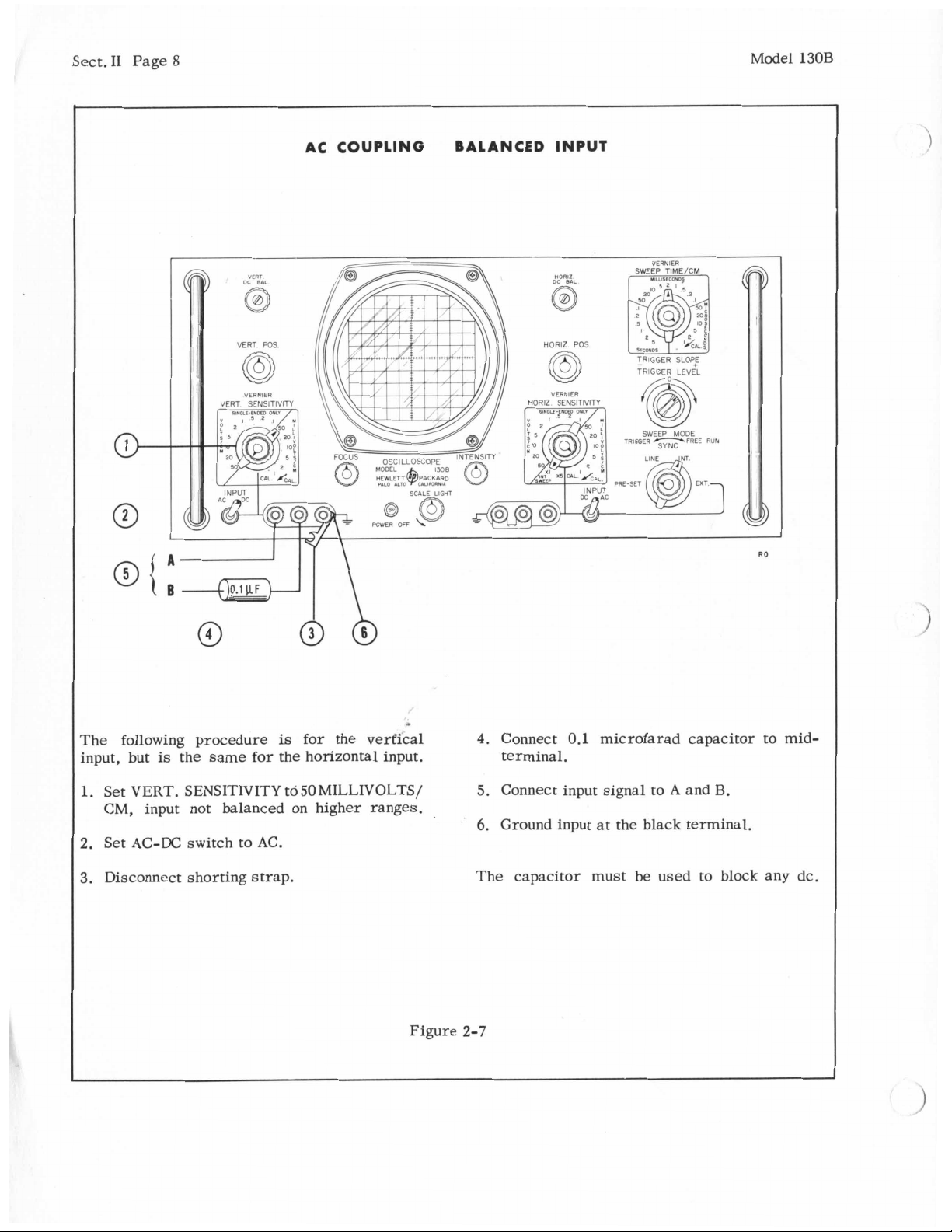
AC COUPLING BALANCED INPUT
VERT
POS
The following procedure
input, but
1.
Set VERT. SENSITIVITY to
is
the same for the horizontal input.
is
for the vertical
50
MILLIVOLTS/
CM, input not balanced on higher ranges.
2.
Set AC-DC switch to AC.
3.
Disconnect shorting strap.
4.
Connect
0.1
microfarad capacitor to mid-
terminal.
5.
Connect input signal
6.
Ground input at the black terminal.
The capacitor must
to
A
and
be
used to block any dc.
RO
B.
Figure
2-7
Page 16

Model
130B
CONNECTION TO CRT DEFLECTION PLATES
Sect.
I1
Page 9
The following procedure
ternal signals to
but
is
the
1.
Remove rear access plate fastened by four
the
same for the horizontal plates.
is
for connecting ex-
vertical deflection plates,
screws.
2.
Remove
cal
replace them with
the
shorting bars between
Amplifier and terminals
1
megohm,
D3
the
and
1/2
resistor.
Verti-
D4
and
watt
Figure
For balanced AC coudinp:
3.
Connect balanced signal through appropriate
capacitor to
D3
and
D4.
For single-ended AC coupling:
4.
Bypass
D4
to chassis
with
capacity.
5.
Connect
the
signal to
D3
through an appro-
priate capacitor.
NOTE:
deflect
and connect
If
the
it
is
desired to have positive voltage
beam
downward, bypass
the
signal to
D4.
2-8
an
adequate
D3
tochassis
Page 17

Sect.11
Page
10
EXTERNAL INTENSITY MODULATION
Z
AXIS
02
POSlTNE
DEFLECTS
RT
d
D3
POSITIVE DEFLECTS UP
VERT
I
RO
CA
Model
L
130B
d
CAUTION: Dangerous Voltages
this terminal board. Be sure the instrumekt
turned
To
signals:
1.
off
when making this connection.
intensity modulate the CRT with external
Remove
small screws
rear
access
at
rear
plate fastened
of
are
present-on
dust cover.
by
four
is
2.
Remove shorting
3.
Connect modulating signal
A
positive voltage
the CRT trace from normal intensity.
bar.
of
to
20
volts peak will blank
these terminals
Figure
2-
9
Page 18

Model
130B
Sect.11 Page
11
ALIGNING SCOPE TRACE
WITH
GRATICULE
RO
CAUTION: DANGEROUS VOLTAGES ARE
PRESENT INSIDE THE INSTRUMENT
Remove two screws at rear of dust cover and
slide cover off to rear. Fiber lever
both
radial and longitudinal positioning of CRT
and
is
locked by clamp
(1).
(2)
controls
Figure
To align sweep trace with graticule loosen clamF
(1)
with a screwdriver. Rotate fiber arm
until
the
trace
is
parallel to horizontal lines
graticule. Tighten clamp
(1)
after adjustment
has been made.
2-10
(2)
on
Page 19

Sect.
111
Page
0
Model
130B
r--
I
I
J
I
c
0
L
a
FW
3-
a5
+-I
3n
or
a
E
(d
k
bn
(d
8
c
0.
-I
a
4
al
k
3
bn
iz
OU
I
I
Page 20

Model 130B
J
Sect.111 Page
1
3-1
GENERAL CONTENT
This section contains a brief description of the
over-all operation of the Model 130B Oscilloscope,
description of each major section and detailed
description
3-2
The block diagram in Figure
circuits of the Model 130B Oscilloscope.
A.
VERTICAL AMPLIFIER
The Vertical Amplifier receives the input
signal, amplifies it, and drives the vertical deflection plates of the cathode ray tube. In addition,
this
amplifier determines the vertical position of
the spot on
chronizing
B. HORIZONTAL AMPLIFIER
The Horizontal Amplifier receives
either from
Sweep Generator, amplifies
zontal deflection plates of
Except for
fier
for amplifying the internally- generated sawtooth voltage,
Vertical Amplifier.
SflEEPGENERATOR
The Sweep Generator forms a sawtooth volt-
to control
across
Generator
generator,
the
sawtooth. The trigger generator controls
allow
sawtooth sweep begins.
of
a Schmitt trigger.
OVER-ALL OPERATION
3-1
the
screen
the
sweep
the
the
provisions in
the
the
face of
is
divided into two parts:
2)
the
operator to choose
and supplies a signal for syn-
with
the vertical input signal.
horizontal INPUT jack or from the
it
and drives
the
cathode ray
the
Horizontal Ampli-
it
is
essentially
horizontal movement of the spot
the
cathode ray tube. The Sweep
a
trigger generator, which starts
the
point at which the
shows the basic
its
signal
the
hori-
tube.
the
same as
1)
a
sawtooth
the
SECTION
THEORY
In addition to forming the 'internal sweep of the
oscilloscope,
the required unblanking pulse
trace during
D.
CALIBRATOR
An
nominal frequency of 300 cps,
ting
the
either
to CAL., turns
and connects
E. CATHODE
accelerator type. It
P1 phosphor screen but
P11 phosphors also and P2 upon special order.
All are electrically interchangeable and the tube
easily changed.
makes possible
which requires no resetting when adjusting the
FOCUS or INTENSITY controls.
plate terminals are connected through removable
jumpers at
rect connections to the plates
3-3
The vertical amplification channel consists of
three parts:
ator,and the amplifier section proper.
A.
is
capacitor
DC
attenuator.
the VERT. or HORIZ. SENSITIVITY switches
The cathode ray tube
VERTICAL AMPLIFICATION CHANNEL
AC - DC
The signal comes into the input terminals and
fed to
position, the signal goes directly to
the
each
sweep.
internal square-wave calibrator, with
basic gain of the amplifiers. Turning
on
its
output to the appropriate amplifier.
RAY
a
the
rear of the instrument
the
SWITCH
the
AC-DC switch. For ac coupling,
is
switched into
OF
Sweep Generator also supplies
the
calibrator supply voltage
TUBE
is
normally supplied
is
The
simple astigmatism adjustment
OPERATION
which
brightens
is
provided for
is
a SAQP - mono-
available
mono-accelerator anode
in
The
the
deflection
so
can
be made easily.
AC-DC
switch,
the
signal path.
the
input attenu-
set-
with
P7 and
that di-
In
the
input
111
the
a
a
is
a
the
Page 21

Sect.
111
Page 2 Model 130B
B. INPUT ATTENUATOR
is
a
The input attenuator
switch having fifteen calibrated ranges (1 MILLIVOLT/CM
sition. When the switch
the input of the amplifier
to
the output
less
ended frequency -compensated attenuators
inserted ahead of the Vertical Amplifier.
six most sensitive ranges, balanced-type attenu-
ators
amplifier (V2) and the third differential amplifier
(V3).
input signals may
after
The sensitivity may
ranges by means of the VERNIER control.
C.
VERTICAL AMPLIFIER
The Vertical Amplifier consists
of
balanced differential amplifiers* in cascade.
The first stage (Vl) has the VERT. DC BAL. adjustment (RlOA,
adjusts the current division between the two halves
of
the stage. The second
control in the cathode circuit which varies the
gain
SENSITIVITY switch, and another dc balance adjustment (R20)
stages,
the coupling
of
the amplifier arising from the inter-electrode
capacitances. The output
fed
to the balanced attenuator
SITIVITY switch. The output
tenuator
ential amplifier (V3). The .third stage has two
potentiometers in its cathode circuit, one controls
the vertical position of the pattern (VERT. POS)
and the other adjusts the basic gain of the Vertical
Amplifier (R40, Gain Adj.). The fourth balanced
differential amplifier (V4)
The neon lamps in the grid-cathode circuit
protect the tube when the Model 130B
turned
deflection plates
dition, synchronization signals
to
50
VOLTS/CM) and a calibrate po-
is
of
the internal calibrator.
sensitive than
are
inserted between the second differential
On
the six most sensitive ranges, balanced
removing the jumper
of
the amplifier between ranges
neutralizing capacitors
effects
is
connected
on.
The output
50
MILLIVOLTS/CM, single-
be
applied
to
be
varied continuously between
B)
in its cathode
is
also
provided.
between the input and output
of
to
the third balanced differ-
of
V4 drives the vertical
of
the cathode ray tube.
sixteen position
in the CAL. position,
is
directly connected
On
ranges
On
to
the input terminals
the ground terminal.
of
four
stages
circuit
stage
has a VERNIEK
of
In
the
are
used
the second
of
the VERT-. SEN-
of
the balanced
is
the output stage,
are
coupled from
which
the VERT.
last
three
to
cancel
stage
of
is
first
In
are
the
is
at-
V4
ad-
the plates
erator
TERNAL
a
precaution against drift and hum, a regulated
dc
supply
stages.
3-4
The Horizontal Amplifier
to the Vertical Amplifier, except in the INT.
SWEEP
SITIVITY switch.
signal from the Sweep Generator
the sweep attenuator to the grid
third balanced differential amplifier.
X5 position, R164, X5 Mag. Adj., in the cathode
circuit
obtain sweep magnification
V104 drives the horizontal deflection plates
cathode ray tube.
3-5
The sweep generator provides a sawtooth voltage
to produce linear horizontal movement
spot
the HORIZ. SENSITIVITY switch
SWEEP (X1
erator
the cathode ray tube during each sweep.
The sweep generator consists
erator,
Cathode Follower.
A. TRIGGER GENERATOR
The purpose
receive
into
the Sawtooth Generator.
The Trigger Generator consists
lector
and
selector
1) the Vertical Amplifier (internal synchro-
nization,
of
V4 and coupled into the Sweep Gen-
to
trigger the sweep during either IN-
+
or
INTERNAL - synchronization. As
is
used
for
the heaters
HORIZONTAL AMPLIFICATION
CHANNEL
is
X1
and
X5
position of the
In
these positions, the sawtooth
of
V104 sets the gain
SWEEP GENERATOR
of
the first three
essentially identical
of
the amplifier
of
X5.
HORIZ.
is
of
The output of
SEN-
fed through
V103, the
In
the INT.
of
of
across
a
a
the
face
of
the cathode ray tube when
is
set
to
or
X5). In addition, the sweep gen-
furnishes the pulse required to unblank
of
a
Trigger Gen-
a
Sawtooth Generator, and a Gate Out
of
the Trigger Generator
a
synchronizing signal and convert
fast,
constant-amplitude pulse
of a SYNC
switch (S201), a Trigger Amplifier (V201),
Trigger Generator (V202). The SYNC
switch accepts a signal from:
+
or
-),
to
to
the
the
INT.
is
to
it
start
se-
*
Valley and Wallman, “Vacuum Tube Amplifier”,
Massachusetts Institute
Series, vol.
Company, Inc., New York, 1948.
18,
pp 441-451. McGraw-Hill Book
of
Technology Radiation
2) an internal
synchronization),
3) the horizontal INPUT terminals (external syn-
chronization).
6.3
volt source (line-frequency
or
Page 22

)
Model 130B
is
fed
to
The synchronizing signal
amplifies the signal and delivers
phase,
to the Trigger Generator. Adjustment
TRIGGER LEVEL control
V201, determining the point on the input waveform
that
Trigger Generator (V202)
cuit: a discussion
A
and B, having both plate-to-grid and cathode-tocathode coupling. The
states:
conducting,
action the change-over from one state to the other
is
in the square-wave output. The levels
the change-over takes place (hysteresis limits)
can be adjusted to
ger Generator (V202)
Start-Stop Trigger (V203).
the A side grid voltage must
hysteresis limit to change the
For
the grid voltage positive through the upper hysteresis limit
grid voltage negative through the
limit
side into conduction.
as
selected by the TRIGGER SLOPE switch,
sets
will
trigger the Trigger Generator (V202).
is
of
the Schmitt trigger follows:
Schmitt trigger consists
circuit
A
side conducting, B side
A
side cut
very rapid, producing fast
example,
will
if
the A side
will
put the A side out of conduction and B
off.
be
close
or
have no
together as in the Trig-
widely spaced
effect,
a
Schmitt trigger
of
two amplifiers,
Due to regenerative
rise
To
trigger the
cross
state
is
conducting, driving
V201 which
it
in the proper
of
the output level
cir-
has
two
stable
cut
off; B side
and decay times
at
which
as
in the
circuit,
a
particular
of
the circuit.
but driving the
lower
hysteresis
the
of
A
Sect.
111
Page
of
the cathode ray tube. The rate
sweep takes place
of
the RC network in the grid circuit
These values
switch. The output
neon lamp (1203) to the Integrator Cathode
lower (V206A). I203
improve the high-frequency response
and a
series
ency toward oscillation. I204 through I206
tective neons
time switch.
The output
(V206A)
sweep attenuator to the Horizontal Amplifier
and 2)
lower
back
ducts and the
charges. However,
V207B
charges, maintaining
of
between sweeps
cover. The bias which determines the triggering
level
plied by the Retriggering Bias Control (V207A).
The bias
R218, in the grid
to
(V207B) in the Sawtooth Generator feed-
circuit.
V203A. This hold-off bias allows sufficient time
of
‘are
resistor
for
of
is
fed
the Retriggering Hold-Off Cathode Fol-
is
cut
the Start-Stop Trigger (V203A)
is
adjusted by the SWEEP MODE control,
is
determined by the values
varied by the SWEEP TIME
of
V206B
is
shunted with a capacitor to
is
used to eliminate any tend-
the timing capacitor in the sweep
the Integrator Cathode Follower
to
two
circuits:
During the Sweep, V207B con-
capacitor
at
off
and the cathode
for
circuit
in
its
the termination
a
positive bias on the grid
the Sweep Generator
of
V207A.
at
which this
of
V206B.
is
fed througha
Fol-
of
the circuit,
are
pro-
1)
through the
cathode circuit
of
the sweep,
capacitor
is
to
dis-
re-
sup-
3
j
B. SAWTOOTH GENERATOR
of
The Sawtooth Generator consists
Stop Trigger (V203), and Integrator Switch ‘(V205),
a
Feedback Integrator (V206B), and Integrator
Cathode Follower (V206A), and
Hold-Off Cathode Follower (V207B).
Start-Stop Trigger (V203).
cuit,
is
fed by Trigger Generator (V202). The
square wave output
Integrator Switch (V205), which in turn controls
the action
V203 produces
cut
off
Feedback Integrator (V206B), a Miller integrator
circuit*, generates essentially
rising waveform, which
tal Amplifier to sweep the trace across the face
*
Millman and Taub, “Pulse and Digital Circuits”
pp 216-228, McGraw-Hill Book Company, Inc.,
New
00013-2
of
Feedback Integrator (V206B). When
permitting V206B
York, 1956.
of
a
negative pulse,it
a
V203
to
is
applied to the Horizon-
a
Retriggering
Schmitt trigger
is
fed directly to the
causes
commence operation.
a
positive linearly
Start-
cir-
V205
to
C. GATE OUT CATHODE FOLLOWER
of
Another function
is
to
furnish a pulse
tube. The
couples the required positive unblanking pulse
from the Start-Stop Trigger
crt
for
3-6
The low-voltage power supply consists
regulated voltage supplies, three positive (+585V,
+300V,
nishing the plate voltages and dc filament voltages
required
The operation
similar; only the -150 volt supply
cussed. V306, V307 and V308 constitute the
voltage regulator circuit
V308,
erence voltage
Gate
Out Cathode Follower (V204),
the duration
LOW VOLTAGE POWER SUPPLY
+lOOV)
for
the instrument.
a
glow discharge tube, probides
of
and one negative (-15OV), fur-
of
each
for
the Start-Stop Trigger
to
unblank the cathode ray
to
the grid of the
the sweep.
of
the four regulators
will
for
the -150 volt supply.
the cathode
of
V307, the
of
be
a
four
is
dis-
ref-
Page 23

Sect.
111
Page
4
is
Control Tube. V306, a Series Regulator,
trolled by the voltage at the plate of V307.
output voltage from the
rectifier
increases,
con-
If
the
the
bias of V307 decreases, causing V307 todraw more
current.
the
This
lowers the plate voltage
grid voltage of V306, resulting
of
V307 and
in
greater plate
resistance for V306. Increased plate resistance
causes a greater voltage drop across V306, compensating for
rectifier
output
.
If
the
output voltage from the rectifier decreases,
the
reverse
supply voltage due to changes
minimized
voltage
the
-150
for
the
3-7
The
HIGH-VOLTAGE POWER SUPPLY
high-voltage power supply provides regulated
dc voltage to the cathode and control grid of
the
increased output voltage from the
and resulting
in
substantially constant
of the above action occurs. Changes
in
load current are
in
the same manner. Thus,
is
held essentially constant. The output of
volt supply
three
positive-voltage supplies.
serves
as
the
reference voltage
the
in
output
the
cathode ray tube. The high-voltage power supply
consists of
an
RF Oscillator tube (V313). a high-
voltage transformer (T302), high-voltage recti-
fiers
(V310.311) and a High-Voltage Control Tube
(V312). The RF Oscillator, a Hartley circuit,
oscillates at a frequency of approximately
100
kc.
The high-voltage transformer has two separate
secondaries which feed the High-Voltage Rectifiers.
The output of V310
the
cathode ray
is
fed to
a
dc-coupled amplifier. The output
fed back to
in
proper phase to oppose any change
the
the
voltage output. The INTENSITY control
output of
cathode of
The output of
of
the
is
cut off. During
this
supply determines the voltage
the
V311
cathode ray tube, and normally
is
connected to the cathode of
tube.
A
fraction of this voltage
High-Voltage Control Tube V312,
of
V312
screen of RF Oscillator tube (V313)
in
the
high-
in
the
on
the
cathode ray tube.
is connected to
the
sweep operation, a positive
the
control grid
the
crt beam
is
Model 130B
pulse from
in
the Sweep Generator circuit overrides
tive crt grid cutoff voltage and unblanks
ray
tube.
justed with the
(R343).
3-a
The
Calibrator, a square-wave oscillator, pro-
the
Gate Out Cathode Follower (V204)
The
brilliance of the trace may be ad-
Intensity
in
series
CALIBRATOR
with grid-voltage supply.
the
nega-
the
cathode
Adjust potentiometer
duces an accurate voltage across R244 for application to either amplifier for setting the basic
gain. Turning either
SENSITlVITY
switches
brator and connects its output to
the
VERT. or HORIZ.
to CAL. turns
the
on
the
Cali-
appropriate
amplifier.
The Calibrator consists of two neon lamps (I207
and 1208) in a relaxation oscillator circuit. Operation of the Calibrator
When
the
+300 volt supply
is
as follows:
is
applied to
the
Calibrator, 1207 will ionize first due to higher potential across it compared to
1208.
When
I207 fires
R243. However,
it
the
voltage at
R242, C213 and R243 will build
the
voltage across a capacitor cannot change
stantaneously.
change,
the
As
C213 allows this voltage to
voltage at
I207 and I208 will also change, since
drop across the ionized neon lamp
(approximately 60 volts).
the
potential across
will draw
the
current
the
junction of
up
slowly because
common junction of
the
is
As
the voltage at
through
in-
voltage
constant
the
common junction of I207 and I208 reaches approximately +70 volts, I208 will
current through R240 and
age across I207 and
it
will de-ionize. I208 remains
fire.
R241
This additional
will reduce
the
volt-
lit until the voltage across C213 charges through
R243
to a voltage approximately 70 volts below the
voltage that appears at
and 1208. I207 will now
the
common junction of I207
fire
and the action will
repeat itself.
I208
is
thus
alternately turned off and on at a rate
of approximately 300 cps. The output of
brator
is
taken from the current passing through
the
Cali-
R244 and 1208. The output is approximately a
square wave
300 millivolts
which
in
amplitude.
can be
set
with
R240 to obtain
Page 24

Model
130B
Sect. IV Page
1
1
4-1
INTRODUCTION
This. section contains instructions for testing, ad-
justing, and trouble shooting the Model
Oscilloscope.
Standard, readily available components are used
for manufacture
sible. Special components are available through
your
local
stock
for
your convenience.
When ordering parts, specify instrument model
serial
and
and stock number appearing in the Table of Replaceable
Your
facilities
you with any problems you may have with
instruments.
Parts.
local
and specially trained personnel to assist
of
@
instruments whenever
@
Representative who maintains a part
number plus the component description
@
Representative maintains complete
130B
pos-
@
SECTION
IV
MAINTENANCE
The following
and adjusting the Model
manufacture. Equivalent test equipment may
be
used.
1)
A
high impedance dc vacuum tube voltmeter,
such
as
DC
Voltage Multiplier.
2)
A
high impedance
such
as
an @ Model
3)
A
variable power line transformer with a mini-
mum rating of
4)
A
square-wave generator such
211A.
5)
A
sine-wave oscillator with a maximum
quency
@
of
Model
test
equipment
an @ Model
3
amps.
at least
200CD.
is
used for testing
130B
Oscilloscope during
410B
with an @ Model
ac
vacuum tube voltmeter,
400D/H/L.
as
500,000
cycles, such as
459A
an @ Model
fre-
an
\
1
The material in this section
to circuit functions, each section having a com-
plete
set
of
adjustment instructions. The material
in this section
4-2
Simple Check Procedure
4-3
Removing the Cabinet
4-4
Isolating Troubles
Connecting
4-5
4-6
Tube
Condensed
4-7
4-8
Adjustment Procedure
4-9
Turn On
4-10
Power
4-11
Replacing and Adjusting the CRT
4-12
Checking and Adjusting the Calibrator
4-13
Adjusting the
4- 14
Adjusting the Horizontal Amplifier
4-15
Phase Shift Adjust
4-16
Adjusting
4-17
Adjusting the Sawtooth Generator and Sweep
Amplifier
00013-2
is
as
follows:
for
230
Replacement
Test
Supplies
Vertical
Preset
and Adjustment Procedure
is
divided according
to
Major Sections
Volt
Operation
Amplifier
6)
An accurate time mark generator suitable
sweep speed calibration.
4-2
This check should
strument malfunction
sary to remove the instrument from the cabinet.
Set both VERT. and HORIZ. SENSITIVITY switches
on
tilted at
should
zontal and vertical directions.
If the proper pattern
both the Vertical and Horizontal Amplifier, the
Power Supplies and the Calibrator
properly.
as
SIMPLE CHECK PROCEDURE
be
performed
is
suspected.
CAL. The pattern should
45
degrees. In addition, the deflection
he
a
total of six centimeters in the hori-
is
obtained,
To
check the Sweep Generator proceed
follows:
first
whenever in-
It
is
be
a
straight line
it
is
are
not neces-
likely that
functioning
for
.
Page 25

Sect.
IV
Page 2
HORIZONTAL AMPLIFIER
BOARD
POWER SUPPLY BOARD-
/
HIGH VOLTAGE RF OSCILLATOR,
TRANSFORMER
AND CONTROL CIRCUIT
SENSITIVITY
SWITCH
SWEEP TIME/CM SWEEP GENERATOR,
SELECTOR SWITCH SYNC CIRCUIT AND
S204
\
CALIBRATOR BOARD.
(SWINGS OUT)
Model
VERTICAL AMP1
BOARD
S2
130B
.I
FlER
\
POWER SUPPLY BOARD
I
j2
IN
5102
IN PARALLEL WITH TiE
HORIZONTAL INPUT TERMINALS VERTICAL INPUT TERMINALS.
PARALLEL
WITH
THE
HORIZONTAL AMPL
BOARD
VERTICAL AMPLIFIER
BOARD
VERTICAL SENSITIVITY
SELECTOR SWITCH
LO
- L -
2198
I
FlER
S2
1
Figure
4-1.
Location Diagram
for
Major Circuits
1
/
Page 26

)
?
Model
1)
CAL, switch HORIZ. SENSITIVITY switch
SWEEPX1.
2)
SECOND.
should appear on the screen.
tained
switch
to
malfunction
4-3
In the cabinet model, remove the
the rear
ment forward.
If the
as
which pass through the front panel, and withdraw
the chassis. If the instrument
turn
trols), remove the two
lift
4-4
Determining which major section contains a malfunction
following general rules are remembered.
1)
usually be traced
2)
Horizontal Amplifier also
generated sweeps, while
stages affects only the Horizontal Amplifier.
3)
generated sweeps only, and does not
Horizontal Amplifier.
130B
Leaving the VERT. SENSITIVITY switch in
to
INT.
Switch SWEEP TIME/CM switch to 1 MILLI-
A
six centimeter square-wave pattern
If no pattern
be
sure SWEEP MODE
is
in INT., and adjust TRIGGER LEVEL
trigger. If a pattern cannot be obtained, the
is
most likely in the Sweep Generator.
REMOVING THE CABINET
is
in PRESET, SYNC
two
of
the cabinet, and push the instru-
130BR
described in Figure
it
off
ISOLATING TROUBLES TO MAJOR
S
A
failure affecting all major sections can
A
failure occurring in the last
A
sweep Generator failure affects internally
has been rack-mounted with brackets
1-3,
remove the
is
out
on
its
face (handles
the dust cover.
ECTlO NS
is
usually not a difficult process,
to
the power supply.
will
screws
protect the con-
at the rear, and
two
will
affect internally
a
failure in
stages
screws
of
the rack,
the
first
affect
is
ob-
screws
if
the
of
the
two
the
at
Sect.IV Page
plates has unbalanced voltages,
control must
center
in that amplifier. If both
have unusual voltages, look
power supply.
5)
major sections
6)
amplifier, such as are used in the Vertical and
Horizontal Amplifiers on the:
and, unless
motionless in the center
whether this signal
or
positioning
move from the center
strument ages
occur which must be compensated by internal adjustments. However, should there be a component
failure in either amplifier the spot
off
ment
isolate the trouble, begin by shorting together the
grids
trace
ahead
the amplifier. If shorting the grids of one stage
does not return the spot to the screen, the
in this stage, or
this stage,
7)
SWEEP TIME/CM switch
SECONDS/CM, turn the SWEEP MODE control to
FREE RUN, and observe
These are the three neon lamps near V206 (6AW8)
on the Sweep Generator etched
these lamps flicker regularly, the Sweep Generator
the TRIGGER region should stop the generation
of sweeps and, hence, the flickering
lamps.
to
If the
The
two
is
supplied by an internal source, such as a
the screen and usually out
of
of
(spot) returns
of
To
check the Sweep Generator quickly,
is
sweeping. Turning the SWEEP MODE into
be
turned
balance these voltages, look
series
sides
or
the balance and positioning controls.
the amplifier closest
this stage. Proceed towards the front of
it
heater string should open, all
will
of
a
signal
balance control, causes the spot to
it
is
if
may be out
far
sets
be
inoperative.
the direct-coupled differential
is
present, the spot
of
is
applied
of
the screen.
to
be expected that a drift
to
the screen, the fault
there
is
of
or
if
the position
from
its
mechanical
for
trouble
of
deflection plates
for
trouble in the
130B,
the screen. Any signal,
to
to
a balancing control in
adjustment.
to
1201, I202
are balanced
will
be
the input terminals
As
the in-
will
will
be
thrown
of
range
of
adjust-
To
If
the output.
5
or
10
and
circuit
board.
of
the
fault
set
the
MILLI-
1203.
the neon
is
is
3
If
.j
4)
If following the Simple Check Procedure does
not produce a trace or spot on the screen, measure the voltages on the deflection plates
Cathode-Ray Tube (deflection plate terminal board
is
a convenient place
VERT. and HORIZ. SENSITIVITY switches
50
MILLIVOLTS/CM, these voltages can
to approximately 480 vdc using the position controls, look for trouble in
of
the power supplies. If one
to
measure).
the
high voltage section
set
of
the
If,
with both
set
to
be
set
of deflection
00013-2
4-5
CONNECTING FOR
Unless otherwise requested by the customer,
instruments are shipped with their power transformer primaries connected in parallel for operation on
To
ment from
the
115
convert
two
screws
volt (nominal) power lines.
to
230
its
cabinet
at
230
VOLT OPERATION
@
volt supply, remove the instru-
or
dust cover by removing
the rear of the chassis, and
Page 27

Sect.
IV
Page 4
Model 130B
push the chassis forward. At the primary of the
power transformer (marked A), remove the
connecting terminals 2 and
connect
1
to 2 as shown in Figure 4-2, and
5,
and 1 and
4.
wires
Then
re-
place the 2 amp slow-blow fuse (F301)witha 1-1/4
amp slow-blow
fuse.
The instrument may now be
connected to the 230 volt line.
115
V
CONNECTION
230V
CONNECTION
Figure 4-2. Line Voltage Connection
4-6
In many
rected by replacing
fore changing the setting
TUBE REPLACEMENT
cases
instrument malfunction can be cor-
a
weak or defective tube. Be-
of
any internal adjust-
ment, check the tubes. Adjustments made in an
attempt to compensate
for
a defective
tube
will
often complicate the repair problem.
It
is a good practice to check tubes by substitution
rather than by using a “tube checker”. The
re-
sults obtained from the “tube checker” can be misleading. Before removing a tube, mark it
if
the tube
is
good it can be returned to the same
so
that
socket. Replace only tubes proved to be weak or
defective.
Any tube with corresponding standa.rd EIA
characteristics can
be
used as a replacement.
Where variation in tube characteristics
circuit
performance, an adjustment
(JEDEC)
will
is
provided.
affect
The following table lists the tests and adjustments
which should be performed
if
such tubes are
re-
placed.
The chart in Table 4-2 lists
all
tubes in the 130B
with their functions and adjustments required when
replacing tubes. The heaters
operated in
series
from a regulated dc voltage
of
some tubes
are
obtained from the Low-Voltage Power Supply.
These tubes are identified in the chart with an
asterisk and their heaters
are
shown in the
Fila-
ment and Primary Detail Schematic. If a tube in
the dc string
the string
is
pulled or burned out, all tubes in
will
be turned off.
Page 28

Model
130B
Sect.IV Page
5
4-7
All basic
CONDENSED TEST AND ADJUSTMENT
PROCEDURE
tests
and adjustments are covered in graphs
the following Table
table will cover
all
normal adjustment needs for
the oscilloscope. For
tailed
If
4-1.
In most cases, this
If
a
more complete and de- complete the indicated adjustments.
test
the
instrument
4-3
a
tube
procedure
and
4-6.
is
replaced,
refer
is
not operating,
to paragraph
refer
refer
to Table
4-8.
to para-
4-2
and
Page 29

I
I
Test
1.
LowVoltage
Power Supply
2. Vertical ampli-
fier
balance
3.
Vertical
VERNIER
balance
4. Vertical ampli-
fier
gain
6. Horizontal
amplifier
balance
7.
Horizontal
VERNIER
balance
8.
Horizontal NONE
10. Sweep
preset
11.
Sweep
I
External Equipment Required
DC
vtvm with
1%
accuracy
,
NONE
NONE
400 cycle
Voltage Calibration Generator
Square Wave
Generator
NONE
NONE
NONE
Square wave
generator
Time Marker
Generator
DC VTVM
Sine Wave
Oscillator
TABLE 4-1. CONDENSED TEST AND ADJUSTMENT PROCEDURE
Procedure
Measure
supply outputs should be within
the following limits:
HOR.SENS.
SWEEP MODE to free-run,
SYNC
to
inpt terminals and
for DC.
VERT. SENS. and Vernier
Cal.
VERT.SENS.
Center VERT.DC.BAL control
(knob).
Short circuit input terminals
and
VERT.SENS. to 1 mv/cm,
VERNIER
VERNIER fully CCW
VERT.SENS.
VERNIER
mv
erator to vertical input.
Connect 50 kc square wave
Vert. Input. Adjust square
wave generator
flection. SYNC to
SWEEP MODE and TRIGGER
LEVEL for stable Dicture.
VERT.SENS. and VERNIER
CAL, SWEEP MODE to
run: SWEEP TIME
Short-circuit input terminals and
set
to 50 mv/cm, with no input.
HORSENS. and VERNIER
HOR.SENS.
Center the HOR.DC
trol (knob).
Short-circuit input terminals and
set
HORSENS.
VERNIER
VERNIER fully CCW.
HOR.SENS. and VERNIER
HORSENS.
Connect 50 kc square wave to
Hor.
deflection.
HOR.SENS. to INT.SWEEP X1
SWEEP TIME
VERNIER to CAL;
from generator
SYNC to
MODE and TRIG.LEVEL for
stable pattern.
HOR.SENS.
HOR.SENS. to INT.SWEEP X1.
SWEEP TIME
SWEEP MODE to PRE-SET,
SYNC to
Connect VTVM 30 volt
between center arm
pot (R220) and ground.
HOR.SENS.
SWEEP TIME to
SYNC
sine wave
Adjust level and VERT SENS.
produce 6 cm
all
low voltage power
i
6
-150
+loo
.
+300
+-,
+585 +25 volts
to
INT.SWEEP X1,
to
INT.,
1.0
SWEEP TIME
ms/cm, short-circuit
volts
*
4 volts
f
12 volts
set
INPUT
to
to
1
mv/cm,
set
INPUT
for DC.
to
Cal.
to
50 mv/cm.
to
p-p
Cal. Connect
from Calibration Gen-
300
to
for
6 cm de-
INT,
Adjust
to
free-
to
1
ms/cm.
INPUT for DC. VERTSENS.
to
to
1
mv/cm,
BAL
con-
INPUT
for
DC.
to
1
mv/cm,
to
CAL.
to
to
50 mv/cm,
inplt and adjust for 6 cm
to
1
ms/cm,
1
kc markers
to
VERT. input.
INT. Adjust SWEEP
to
INT.SWEEP X5.
to
1
ms/cm,
EXT.
to
JNT.
to
with no input.
to
Connect 500 kc
vertical input.
vertical
range
of
Preset
INT.SWEEP X1.
1
ms/cm.
deflection.
CAL
CAL.
to
If
adjust R332
Center bottom of calibrating
signal with VERT.POS. control
Center
ance control. (Screw adjustment
in center
Center spot
VERT. POS. control.
Return spot
Adjust R40 for 6 cm deflection.
Adjust C12
Adjust R240
Center the left
HOR.POS. control.
Center the spot with
balance control (screw driver
adjustmellt in center of DC BAL
control).
Center spot with
HORIZ.
Return
Adjust R144 for
spots.
Adjust C114 for
spots.
Adjust R134 for one marker/cm
Adjust R164
apart.
Slowly adjust R220 and note volt-
age
Adjust pre-set for 2 volts more
positive than voltage noted.
Adjust R229 for
10.5 cm long.
Adjust
voltages
are
outside limits,
for
-150 volts.
trace
with coarse bal-
of
DC BAL control.)
(or
trace) with
to
center with R20
for
best square wave.
for
6 cm deflection.
spot
POS.
spot
to
center with R120.
6
best
for
markers 5 cm
just prior to sweep
a
with the
the
cm between
defined
trace
~~
coarse
control
start.
about
Notes
Check sweep calibration
if -150V
Repeat
Repeat
Repeat
Repeat
is
adjusted.
a8
required.
as
required.
as
required.
a8
required.
~~
Page 30

Model 130B
Ref.
Tube
TABLE 4-2. TUBE REPLACEMENT CHART
Function
VERTICAL AMPLIFIER
Ad
jus
tment
Sect.
IV
Page 7
vl*
v2*
v3*
v4*
v101*
v102*
V
103*
V104*
v201*
v202
V203
V204
V205*
v206
V207
12AU7$
12AU7
12AT7
6DJ8/6BQ7
12AU7$
12AU7
12AT7
6DJ8/6BQ7
6DJ8/6BQ7A
12AT7
6U8
6C4
12AL5
6AW8
12AX7
Phase Inverter Amplifier
Differential
Differential Amplifier
Differential Amplifier
HORIZONTAL AMPLIFIER
Phase Inverter Amplifier
Differential Amplifier
Differential Amplifier
Differential Amplifier
SWEEP GENERATOR
Trigger Amplifier
Trigger Generator
Sweep Start-Stop Trigger
Gate
Out Cathode Follower
a. Integrator Switch
b. Integrator Switch
a. Integrator Cathode Follower
b. Feedback Integrator
a. Retriggering Hold Off
b. Retriggering Bias Control
Amplifier
Vertical Amplifier (par. 4-13A/B)
Vertical Amplifier (par. 4-13A/B)
Vertical Amplifier (par. 4-13B)
Vertical Amplifier
Horizontal Amplifier (par.
Horizontal Amplifier (par.
Horizontal Amplifier (par.
Sawtooth Generator (par. 4-17)
none
none
Adj. Preset, Sweep Length
(par. 4-16 and 17, Step.17)
none
none
none
(par.
4-13B)
4-14A/B)
4-14A/B)
4-14B)
V301
V302
V303
V304*
V305
V306
V307*
V308
V309
V310
V311
V312
V313
V314
*
Series dc
12B4
6AU6
12B4
6BH6
6x4
12B4
6BH6
5651
5AQP
1v2
1v2
12AU7
6AQ5
heater
POWER SUPPLY
+300-volt Series Regulator
+300-volt Control
+100-volt Series Regulator
+100-volt Control
-150-volt Rectifier
-150-volt Series Regulator
-150-volt Control Tube
Reference
CRT
High Voltage Rectifier
High Voltage Rectifier
High Voltage Control Tube
RF Oscillator
a. +585-volt Series Regulator none
b. +585-volt Control Tube
Tube
Tube
Tube
3
Tested part - See Table of Replaceable Parts
none
none
none
none
none
none
none
LV Supply (par. 4-10A)
Adj.Vert.& HorizGain (par.4-13,
none
none
none
none
I
none
Page 31

Sect.IV Page
8
Model
130B
rMEASURE
POWER
+300v
7
MEASURE
’
t
REGULATOR BOARD
SUPPLY LOCATION DIAGRAM
IOOV
RECTIFIER CHAS
HIGH VOLTAGE BOARDw
REGULATOR BOARD
Lo-
E
-
118
\L/
RECTIFIER CHASSIS
GATE LEVEL ADJ
I
RECTIFIER CHASSIS
Figure
4-3.
R343
INTENSITY
HIGH VOLTAGE BOARD
Power Supply Location Diagram
ADJ
17342
LI
LO-Y-172
Page 32

Model
4-8
Usually a particular oscilloscope
complete testing and calibration. Only one
tests
completing the entire
The following procedures
mended sequence
bration operation. In general, tubes
cause
fore
placements.
Specifications for the
are given in the front
lowing test procedures contain extra checks to
help you analyze
extra checks and the data they contain can not
considered as specifications.
A
voltage measurements
before
130B
ADJUSTMENT PROCEDURE
will
not need
or
two
will
be
needed and they can
test
procedure.
are
for
a
complete test and
of
trouble and new ones should
making adjustments
a
fifteen minute warm-up and power supply output
making any other
or
($43
Model
of
this manual. The fol-
particular instrument. These
are
always recommended
be
done without
listed in a recom-
are
the main
be
tried
other component
130B
Oscilloscope
test
or adjustment.
cali-
be-
re-
be
Sect. IV Page
To
adjust the power supply section,
ure
4-3,
and proceed
A.
LOW VOLTAGE SUPPLY
1)
Turn sweep generator off by turning the HOR.
SENS. switch
2)
Permit the
minutes
3)
Measure power supply vo'ltages with line volts
set
to
within the limits given in Table
R332
can
volt supply within limits.
If adjustment
sary,
justments must
If poor
the following check may
all
to
at
a line voltage
115
volts. The voltages
be
adjusted
of
sweep timing, calibrator and gain ad-
low
voltage supply regulation
as
follows:
50
volt/cm position.
130B
to
warm up for at least five
of
if
necessary
the
+lo0
volt supply
be
checked.
be
115/230
made:
volts.
will
4-3.
to
refer
normally
set the
was
is
suspected,
to
Fig-
be
Control
+lo0
neces-
9
4-9
When turning the oscilloscope on
time after repair in any circuit, measure
sistance from power supplies to ground. They
usually
When
supply
sitioning controls full counterclockwise
plying power. Failure to
can
TURN
will
+loo
-150
+
300
+585
first
repairs,
cause
ON
be
within
volt supply
turning an oscilloscope on
permanent cathode-ray
25%
of the following:
110
ohms
50,000
85,000
CAUTION
turn the intensity and both
follow
ohms
9,000
ohms
ohms
this precaution
for
after
before
tube
the first
re-
power
po-
ap-
damage.
--------------
4-10
The power supplies in the oscilloscope
tremely stable and
ment. The output voltages should
regular intervals but unnecessary adjustments
should
Power
points indicated in Figure
POWER SUPPLIES
will
require infrequent adjust-
be
avoided.
supply voltages may
4-3.
are
be
measured at
be
measured at the
ex-
--
Check the regulation
voltage
between
ages should remain within
of line voltage.
--
Measure the ac ripple on each supply voltage.
This
specified in Table
TABLE
Supply
+loo
-150
+300
,
+585
If any output does not regulate
ripple, replace the Series Regulator Tube
Control
mind, however, that
volts
will
lation, and that loss
will
cause
lose
regulation
as
the power line voltage
103
and
127
ac
voltage should not exceed the amount
4-3.
REGULATED POWER
SUPPLY TOLERANCES
Tolerance
(115/230
volt line)
v
v
V
V
Tube
cause the other supplies
the
*
4%
4%
*
4%
*
4%
of
that supply. It must
of
+585
volt and
also.
of
volts.
4-3.
Variation
change
loss
of
regulation
each power supply
is
varied
All
regulatedvolt-
f
1%
over this range
I
*lo%
*
1%
1%
*
1%
or
regulation
of
+300
volt supplies
Nominal
115/230V
5
mv
5
mv
60
mv
has excessive
or
be
kept in
of
the
to
lose
regu-
the
+lo0
the
-150
volts
to
Page 33

Sect.IV Page
10
SERVICING ETCHED CIRCUIT BOARDS
Model
130B
Excessive heat or pressure can lift
soldering iron
be cemented
A
break
in
Use
only high quality rosin core solder when repairing etched circuit boards. NEVER USE PASTE FLUX.
After
soldering, clean off any excess flux and coat the repaired area with a high quality electrical varnish
(50
watts maximum) and following these instructions. Copper that lifts off the board should
in
place
with
the copper should
a quick drying acetate
be
repaired by soldering a short length of tinned copper
the
copper strip from the board. Avoid damage by using a low power
base
cement having good electrical insulating properties.
wire
across the break.
or lacquer.
When
replacing components
with
multiple mounting pins such as tube sockets, electrolytic capacitors, and
potentiometers, it will be necessary to lift each pin slightly, working around the components several times
until
it
is
free.
If
the
WARNING:
specific instructions outlined
in
the steps below regarding etched circuit boards without
eyelets are not followed, extensive damage to the etched circuit board will result.
2.
1.
Apply heat sparingly to lead of component to be
replaced.
an eyelet
ponent side of board.
not pass through an eyelet, apply heat to con-
-
ductor side of board.
If
lead
of
component passes through
in
the circuit board, apply heat on com-
If
lead of component
e
Reheat solder
sert a small awl to clean inside ofhole.
does not have an eyelet, insert awl or a
drill from conductor side of board.
in
vacant eyelet and quickly
CONDUCTOR
If
in-
hole
#57
3.
Bend clean tinned leads on,new part and care-
insert
fully
In the
event
method shown below. This
1..
Clip lead as shown below.
This procedure
through eyelets or holes
that either the
is
used
circuit
is
especially applicable for circuit boards without eyelets.
in
the field only as an alternate means of repair.
in
board has been damaged or the conventional method
CLIP
HERE
board.
4.
Hold part against board (avoid overheating) and
solder leads. Apply heat to component leads on
correct side
2.
Bend protruding leads upward. Bend lead of
of
board
3s
explained
in
is
impractical, use
new component around protruding lead. Apply
solder using a pair of long nose pliers as a
heat
sink.
APPLY
SOL DER
It
is
not used within
the
step
1.
factory.
Figure
4-4.
Servicing Etched Circuit Boards
00013-2
Page 34

Model 130B
Sect.IV
Page
11
B. HIGH VOLTAGE SUPP
\
I
1) The -2550 volt output
sistor
an appropriate
410B VTVM with an
Voltage Multiplier)
(marked -2550 CATH.
2) With the line
should measure -2550 *4%. Control R334 can
be
supply within limits.
If poor -2550 voltage supply regulation
pected the following check may
--
3) Set SWEEP TIME/CM to
4) Set HOR. SENS.
board
under the
dc
voltmeter (such
to
at
115/230 volts the high voltage
adjusted if necessary
Check the regulation by varying the line volt-
age
between
should remain within
line voltage. If the -2550 supply does not regu-
late
check the control tube V312.
103
to
Y
-
is
measured
base
of
the
@
Model 459A
the Junction
on
cover).
to
set the -2550 volt
be
and 127 volts. The -2550
~tl%
over this range
5
MILLISECONDS.
INT. SWEEP X1.
on
crt.
as
an @ Model
DC
of
R338, C312
made:
there-
Connect
Resistive
is
sus-
4) With a screwdriver loosen the
socket.
on
supporting the front
DANGER
5) Remove the
CAUTION
6) Insert the replacement
panel and
7) Replace front-panel
8) Adjust the socket assembly
the
clamp just enough
of
Turn the INTENSITY control
first
be
Free
the
crt
the center
crt
just misses the
of
the tube
-
Do
not apply
crt
through the front panel.
-
HANDLE THE CATHODE RAY TUBE
CAREFULLY.
seat
in socket.
to
applying power to
damaged quickly by
------------
crt
base from
from the socket by pressing
base
with one hand while
of
the
crt
with the other.
force
on
neck
of
tube.
crt
through the front
bezel.
so
bezel
assembly. Tighten the
hold the
NOTE
a
crt.
too
that the
crt
in place loosely.
to
minimum when
The phosphor can
much brightness.
face
of
5) Set SWEEP MODE fully clockwise
RUN.
6) Set INTENSITY control to
7) Set Int. Adj., R343, until the
visible.
8)
Set SWEEP MODE fully counterclockwise
PRESET.
9)
Set
INTENSITY control for a low intensityspot.
10)Center spot and adjust FOCUS control and
ASTIGMATISM (R303)
sharply focused spot.
4-11
REPLACING AND ADJUSTING THE CRT
To
replace the cathode-ray tube,
2-10, and proceed
1) Turn off and remove the 130B from thecabinet.
2) Loosen the clamp
model; remove cover from High Voltage terminal
board
to
get
3) Remove the front-panel
access
as
follows:
on
for
screwdriver through board).
10
o’clock.
to
obtain a small round and
the
crt
socket. (Cabinet
bezel.
trace
refer
to
FREE
is
just
to
to Figure
9)
Set the INTENSITY control fully counterclock-
wise. Turn the 130B
10)Set the SWEEP MODE control
11) Adjust the INTENSITY control
weak
trace;
trace,
center the
12) Align
handle
CAUTION
13)Making certain the
touching the bezel assembly, tighten the clamp
on
the
turning. If the
assembly, Newton rings may be visible.
14) Readjust the astigmatism;
15) Check the gain calibration
Horizontal Amplifiers by setting the VERTICAL
and HORIZONTAL SENSITIVITY
and
if
obtain 6 cm vertical deflection and R144 (Figure
4-6)
to
trace;
adjust the FOCUS control
and with the vertical position control,
trace
vertically.
trace
with graticule using the alignment
at
rear
of
crt.
-
Do
tube damage may result.
crt
socket only enough
face
necessary, adjusting R40 (Figure 4-5)
obtain 6 cm horizontal deflection
see
paragraph 4-13B and 4-14R.
on
and allow
not over-tighten
crt
face
to
of the tube touches the bezel
see
of
to
warm up.
to
FREE RUN.
to
obtain
for
crt
clamp
is
close
to
hold the
paragraph 4-10B.
the Vertical and
selectors
crt
a
sharp
but not
from
to
CAL,
on
a
or
to
the
Page 35

Sect.IV Page
12
Model
130B
c12
ADJUST AMPLIFIER FREQUENCY GAIN ADJUSTMENT . FOR
R
20
ADJUST VERNIER BALANCE
(SEE PARA.
4-
13A)
FRONT PANEL+
LEFT SIDE VIEW
SENSITIVITY. CALIBRATION
(SEE PARA.
R
40
4-
136)
Figure
c4
c3
c2
FRONT PANEL
tr
4-5.
Vertical Amplifier Adjustment Location
(SEE PARA.
4-13C)
Page 36

Model
e-
;i
V
&:
130B
/PANEL RAIL
*
0
Q
a
0
0
--._
7
4
a
9
0
m
0
a
0
a
a
0
m
Y
PANEL RAIL
1308-120
(RIGHT
SIDE
BRACKET)
Sect.1 Page
3
Figure
,)
00013-2
1-3.
Model
130BR
Installation
Page 37

1
Y
0
4
e c
c
z
m
E
0
L
c
Lo
=,
7
0
4
z
Y
w
*
Page 38

Model 130B Sect.1V Page
13
4-12 CHECKING AND ADJUSTING THE
CALIBRATOR
Set HORIZ. SENSITIVITY
1)
SWEEP TIME/CM
MODE to PRESET; SYNC. to
GER LEVEL to
If
PRESET (SWEEP MODE)
may not obtain a trace. See paragraph 4-16.
to 1 MILLISECOND; SWEEP response
“0”.
NOTE dicated by Figure 2-2 and paragraph 4-13A.
to
INT.
SWEEP X1;
INT.;
is
maladjusted, you
andTRIG- follows:
------------
2) Set the VERT. SENSITIVITY switch to 50
MILLIVOLTS/CM. Place the VERNIER control
in
CAL.
3)
Connect the signal source to the vertical
PUT terminals and
read on the vtvm, to
2c) and
4)
Adjust
centimeters deflection.
5)
Set
6)
Adjust the R240
Centimeters deflection.
its
R40
(see
the
VERT. SENSITIVITY switch
set
its rms output voltage,
106
millivolts
output frequency
Figure 4-5)
(see
Figure 4-7)
to
to
obtainexactly 6
for
IN-
(300
mv/
1000
cps.
to
CAL.
exactly 6
B.
VERT. AMPL. GAIN AND FREO. RESP. AD-
JUSTMENTS
To
adjust
1) Adjust
2) Set HORIZ. SENSITIVITY to
and set the SWEEP TIME/CM switch
SECONDS, SWEEP MODE
GER LEVEL
3)
Place VERTICAL SENSITIVITY switch and
VERNIER in CAL.
4) Adjust R40
5) Set VERT. SENSITIVITY
CM. Set SYNC to
6)
Set SWEEP TIME/CM switch to 5 MICRO-
SECONDS.
7)
Connect a
INPUT and adjust the square-wave amplitude
6
to 8 centimeters deflection.
the
Vertical Amplifier gain and frequency
refer
Vertical
to
Figure 4-5 and proceed as
and VERNIER balance as in-
INT.
to
to
PRESET and TRIG-
to
“0”.
for
exactly 6 centimeters deflection.
to
50 MILLIVOLTS/
SWEEP
2 MILLI-
INT.
50
kc
square wave to the Vertical
X1
its
for
8)
Adjust C12
4-13 ADJUSTING THE VERTICAL
AMPLIFIER
.~
The
following adjustments are located in the vicinity
SENSITIVITY
A.
strument
tical balance as shown by Figure 2-2.
to Figure 4-5 and proceed as follows:
1)
switch
2) Set VERT. SENSITIVITY
and VERNIER
3)
4)
turn
of
the
Vertical Amplifier
switch
VERNIER BALANCE ADJUSTMENT C. INPUT ATTENUATOR FREQUENCY
To
adjust VERNIER balance, allow
to
warm up 15 minutes and adjust
Short
the
INPUT terminals and set
to
DC.
as shown in Figure 4-5.
to
to
CAL.
Center spot
Turn
spot
(or
trace) with VERT. POS. control.
VERNIER fully counterclockwise and
to
center
with R20, the Bal. Adj.
or
the VERT.
the
Then
the
INPUT
1
MILLIVOLT/CM,
in-
Ver-
refer
re-
a range
variations
connected in parallel with C12
maximum capacity
To
ator
1) Connect a
INPUT.
2)
of
3)
wave presentation on the following ranges:
of
RESPONSE ADJUSTMENTS
adjust frequency response
refer
Set SWEEP TIME/CM
the square wave.
Make the indicated adjustment
for
best
square wave. To give C12
adjustment sufficient
of
tube characteristics. C13 may
to
1340
ppf.
to Figure 4-5 and proceed as follows:
5
kc
square wave
to
VOLT/CM ADJUST
10
now
be
The trace should
NIER
is
rotated.
stationary as the VER-
1
.1
to
compensate for
to
increase
of
the input attenu-
to
the Vertical
obtain
for
c2
c4
3
best
or
c3
be
the
4 cycles
square-
Page 39

Sect.
IV
Page
14
ADJUST FREQUENCY RESPONSE
(SEE PARA. 4-17(14)
Model
130B
C118
r
R144
FOR HORIZONTAL SENS
C114
LADJUST AMPLIFIER FREQUENCY RESPONSE
CFRONT
GAIN ADJUSTMENT
(SEE PARA. 4 -148)
ADJUST VERNIER BALANCE
(SEE PARA. 4-148)
IT
IV ITY CAL I BRAT ION
FREQUENCY RESPONSE
E PARA.4-17(14)
(SEE PARA. 4-14A)
Lo-
L-
164.IC
RO
PANEL
ADJUST
(SEE PARA. 4-17(16)
-ADJUST SWEEP ATTENUATOR
rADJUST FREQUENCY RESPONSE
(SEE PARA. 4-17(5)-
(SEE PARA. 4-17(14)
X5
MAG.
Figure
FREQUENCY RESPONSE
Horizontal Amplifier Adjustment Locations
4-6.
(HORIZ.
A
DJ U STMENTS
(SEE PARA.
SENSITIVITY)
4-14C)
LO-L-
IO*bIC
RO
Page 40

Model 130B
Sect.IV Page
15
4-14
To adjust the Horizontal Amplifier,
ure
A.
strument to warm up thoroughly and adjust Horizontal balance
to Figure 4-6 and:
1)
switch to
2) Set the HORIZ. SENSITIVITY to 1 MILLIVOLT/CM and
3)
4)
wise
Bal. Adj. The spot will now
VERNIER
B.
To adjust the gain and frequency response,
to Figure 4-6 and proceed as follows:
1) Set HORIZ. SENSITIVITY switch to CAL. and
the VERNIER to CAL.
2)
flection.
3)
4) Connect an
the Vertical INPUT of the oscilloscope and to the
SYNC.
ator; adjust the sine wave for 10 cm deflection.
5)
VOLTS/CM.
6) Connect
INPUT, and adjust the square wave amplitude for
6 to
7)
Some vacuum tubes require more capacity for
compensation than the maximum value of C114.
ADJUSTING HORIZONTAL AMPLIFIER
refer
to Fig-
4-6 and proceed as follows:
VERNIER BALANCE ADJUSTMENT
To adjust the VERNIER balance allow the in-
as
shown by Figure 2-3; then
Short the INPUT terminals and set the INPUT
refer
DC.
the
VERNIER to CAL.
Center the spot with the HORIZ. POS. control.
Turn
the VERNIER completely counterclock-
and return the spot to
is
rotated.
AMPLIFIER
RESPONSE ADJUSTMENTS
Adjust R144 for exactly 6 centimeters de-
Set VERT. SENSITIVITY to 2 VOLTS/CM.
IN
terminal of the 211A square wavegener-
Set HORIZ. SENSITIVITY to
8
cm deflection.
Adjust C114 for best square wave response.
GAIN
8
kc
(approximately)
a
50
kc
square wave to the Horizontal
NOTE
the
AND
FREQUENCY
center
be
with R120,
stationary as the
sine
wave to
50
MILLI-
refer
Capacitor C115 may
C114 to increase the maximum capacity to
1340 ppf, permitting
vacuum tubes to
be
be
connected in parallel with
a
greater percentage of
used.
------------
C.
INPUTATTENUATORFREQUENCY
RESPONSE ADJUSTMENTS
To adjust the frequency response at the input at-
tenuator,
follows:
1)
Set
2) Connect
to the Vertical INPUT of the oscilloscope and to
the Sync-In terminal of the 211A square wave
generator; adjust the sine
deflection.
3) Set HORIZ. SENSITIVITY to
(VERNIER in CAL.).
4) Connect
INPUT and adjust
deflection.
5)
Make the following adjustments
indicated for the best square wave response, adjusting the square-wave amplitude to 6
meters
4-15
Phase shift
Amplifiers.
If
the square
Horizontal Amplifier was carefully set, the relative
phase
exceed one degree at frequencies below 50
To check Phase Balance:
1)
Set VERT. and HORIZ. SENSITIVITY to
MILLIVOLTS/CM and VERNIER to CAL.
2) Apply a 50
INPUT and VERT. INPUT. Center
adjust signal amplitude for 6 cm vertical and 6 cm
horizontal deflection.
refer
VERT.
on
each range.
VOLTS/CM
10
PHASE SHIFT
shift
to Figure 4-6 and proceed as
SENSITIVITY
an
800
cps (approximately)
a
5 kc square wave to the Horizontal
its
amplitude for 6 centimeter
to
2
VOLTSICM.
wave
for 10 centimeter
10
on
sine
wave
VOLTS/CM
the ranges
centi-
ADJUST
c102
1
.1
between
wave
response of the Vertical and
between the two amplifiers should not
kc
sine-wave signal to the HORIZ.
C104
C103
ADJUST
Vertical and Horizontal
(see
pattern
Fig. 4-6)
kc.
and
50
Page 41

Sect.IV Page
16
(SEE
WRA. 4-17(11)
Model
130B
LD-S-188B
ADJUST CALIBRATOR
(SEE
PARA.
R
229
ADJUST SWEEP LENGTH
(SEE
PARA. 4-17(17)
f-.SWEEP TIME /CM ADJUSTMENTS
(SEE PARA.
4-17)
4-12,
TUBE SIDE
OF
BOARD (DOOR OPEN)
(CABINET MODEL)
RIGHT SIDE VIEW
(RACK
>
MOUNT
MODEL)
ADJUST
ADJUST
ADJUST
U
-R220
TOP VIEW (RACK MOUNT MODEL)
BOTTOM VIEW (CABINET MODEL WITH SWEEP DECK OPEN)
Figure
Sweep Generator Adjustment Locations
4-7.
UST
.i
SECOND
MILLISECONDS
i
MILLISECOND
RACK MOUNT MODEL ONLY. LOCATED
BELOW THE HORIZONTAL SENSITIVITY
SWITCH ON CABINET MODEL.
ADJUST PRESET
(SEE
PARA.
4-16)
LD-L-165
RO
Page 42

Model 130B
Sect.
IV
Page 17
The opening
exceed
correct
of
the
pattern (Figure 4-6).
4-16
To
adjust
of
the pattern,
a
tenth of a centimeter.
if
any, should not
If
phase difference, adjust C114
ADJUSTING PRESET
Preset
refer
to Figure 4-7 and proceed
necessary to
for
closure
as follows:
1)
Set VERT. SENSITIVITY to OFF, SWEEP
TIME/CM
MODE control maximum counterclockwise
SET.
2) Connect a dc voltmeter between ground
the center tap
3)
Turn R220 fully counterclockwise. Then slowly
adjust R220
begins
switch
to
.1
MILLISECOND and SWEEP
Set SYNC selector to INT.
of
R220
the
PRESET adjust control.
to
clockwise
free
fun.
until the sweep generator
Turn
R220 counterclockwise
to
(+)
PRE-
and
until the sweep just stops and record this voltage
which should
be
about -26 volts.
4) Set R220 to give a voltmeter indication exactly
2 volts less negative than the voltage noted.
4-17
To
Amplifier
ADJUSTING THE SAWTOOTH
GENERATOR AND SWEEP AMPLIFIER
adjust the Sawtooth Generator and Sweep
refer
to Figures 4-6 and 4-7 and pro-
ceed as follows:
7) Adjust R260 (Figure 4-7) for
1
marker per
centimeter.
8) Set SWEEP TIME/CM to
.1
SECOND and con-
nect 10 cycle (100,000 psec) time markers to
the Vertical INPUT.
9)
Adjust R259 (Figure
4-7)
for 1 marker
per
centimeter.
10) Disconnect the time mark generator from
the Vertical INPUT,
switch to
zontal
CM
11)
Disconnect
10
VOLTS/CM,’ the Vertical and Hori-
input switches
to
5 MICROSECONDS.
the
set
VERT. SENSITIVITY
to
AC, and SWEEP TIME/
blue-white lead {Figure 4-7)
from the Sweep Generator board and connect it
through a
1
microfarad capacitor to
the
Hori-
zontal INPUT. Set SYNC to EXT.
12)Connect a wire between V206 pin
1
(6AW8)
and the Vertical INPUT.
13)Connect a
output
of
and adjust
the
its
50
kc
square wave from the 600 ohm
($9
Model 211A
to
theHorizonta1 INPUT
amplitude for about 6 centimeter
deflection.
14)Adjust C113 near
the
HORIZ. SENSITIVITY
switch, and C116 and C118 on the Horizontal
Amplifier board (Figures 4-6 and 4-7), for best
square wave presentation. Remove the
wire
be-
tween V206 pin l and the Vertical INPUT.
1)
Set SYNC
and TRIGGER LEVEL to
2) Set HORIZ. SENSITIVITY
SWEEP TIME/CM
VERNIER
3)
Connect 1 kc
to
to
CAL.
INT.,
SWEEP MODE to PRESET
“0”.
to
INT. SWEEP X1,
to
1
MILLISECOND, and
(1000
p
sec)
time markers
Vertical INPUT.
4) Set R261,
tiometer board,
5)
Adjust R134, Sweep Attenuator, (Figure 4-6)
and HORIZ.
cm. This
as close as
adjustment
6) Set SWEEP TIME/CM
and connect 100 cycle (l0,OOOp
to
the Vertical INPUT.
1
Millisecond Adj., on the poten-
to
its
mechanical
POS.
for approximately 1 time marker/
is
a rather
is
practical. Then make the final
with
R261.
coarse
center.
adjustment. Set
to
10
MILLISECONDS
sec)
time markers
to
its
the
it
15)
Reconnect
Generator board, and
generator
lowing adjustment as indicated for
per
centimeter.
the blue-white lead
connect
to
the Vertical INPUT. Make the fol-
to
the Sweep
the time marker
1
time marker
(Fig. 4-7)
Time Marker SWEEP TIME/CM Adjust
1
1
psec
(
1
mc)
10
psec
(100
kc)
.1
msec(
10
kc)
16)Set HORIZ. SENSITIVITY to
MICROSEC. C227
10
MICROSEC. C225
.1
MILLISEC. C223
INT.
SWEEP
X5,
and adjust R164 (Figure 4-6). for markers 5
centimeters apart.
17)Connect a 500
INPUT,
set
set
SWEEP TIME/CM to 1 MILLISECOND,
SYNC to EXT, and adjust R229, Sweep Length,
(Figure 4-7) fora trace about
kc
signal to the Horizontal
10.5
centimeters long.
Page 43

Model
1.
2.
130B
SCHEMATIC DIAGRAM NOTES
Sect.IV
Heavy solid line shows main signal path; heavy dashed line shows control, secondary signal,
or
feedback path.
Heavy box indicates front-panel engraving; light box indicates chassis marking.
Page 19
3.
Arrows
on
potentiometers indicate clockwise rotation as viewed from the round shaft end, counter-
clockwise from the rectangular shaft end.
Resistance values in ohms, inductance in microhenries, and capacitance
4.
in
micromicrofarads
unless otherwise specified.
5.
Rotary switch schematics are electrical representations; for exact switching details refer to
the switch assembly drawings.
Relays shown
6.
7.
3
indicates asselected part. See parts
Interconnecting parts and assemblies are shown on cable diagram.
8.
9.
*
indicated value adjusted at factory. Part may
Each tube socket terminal
1.
in.
condition prevailing during normal instrument operation.
list.
be
omitted.
VOLTAGE AND RESISTANCE DIAGRAM NOTES
is
numbered and lettered to indicate the tube element and pin number,
as follows:
-
*
-
no tube element
H=
K=
G=
sc
sp
Hm
IS
heater
cathode
control grid
screen grid
=
suppressor grid
=
heater mid-tap
=
internal shield
=
P=
T=
R=
A=
S=
Sh
NC
A=
plate
target (plate)
reflector
or
repeller
anode (plate)
spade
shield
=
no external connection to socket
=
indefinite reading due to circuit (see
2.)
The numerical subscript to tube-element designators indicates the section
of a multiple-section
tube; the letter subscript to tube-element designators indicates the functional difference between
like
elements in the same tube section, such as t for triode and p for pentode.
a
A
socket terminal with
an asterisk may be used as a tie point and may have
voltage and
resistance shown.
Voltages values shown are for guidance; values may vary from those shown due to tube aging
2.
normal differences between instruments. Resistance values may vary considerably from those
shown when
Voltage measured
3.
ments made
the
circuit contains potentiometers,
at
the terminal
with
an electronic multimeter, from terminal to chassis ground unless otherwise
is
crystal diodes,
shown above the line, resistance below the line; measure-
or
electrolytic capacitors.
noted.
solid line between socket terminals
A
4.
terminals;
resistance are given
indicates
a
dotted line between terminals indicates a connection inside the
at
only one of the two joined terminals.
a
connection external to the
tube
tube.
between the
Voltage and
or
Page 44

Sect,
IV
Page
20
+1.9V
IZOK
VERTICAL AMPLIFIER
VOLTAGE - RESISTANCE DIAGRAM
(VIEWED
(12AU7)
PHASE INVERTER
I
t12.6V
20
+52v
I40
IOOK
K
0
FROM
ETCHED
50K
t
450V
+
245
+450
140K
SIDE)
v4
DIFFERENTIAL AMPLIFIER
(6BQ7A/6DJ8)
GI
I
+
245V
40K
+l60V, 6.3VAC
40 K
Model
130B
I
-\y
LD-E-I16
r--
I
v2
(12AU7)
DIFFERENT
+l60V
+55v
7500
AM PLI F IER
I
AL
v2
I
_I
+55v
+38V
+160V
+
140K
40
38K
52V
v3
I
L------
FIGURE
v4
4-8
I
1
I
v3
DIFFERENTIAL AMPLIFIER
+245V
50K
+I58
406
(PAT71
Lo-
+158V
5PK
+
l60V
50K
t
51v
50
+38V
40
+245v
50K
L
-
478.
Page 45

Model 130B
Section
Table 5-2
V
Table 5-2. Replaceable
Description#
Binding Post Assembly:
Insulator, binding post (rack model)
Insulator, binding post (cabinet model)
Tube, elect: 12AT7
Tube,
Connector Assembly
Connector Assembly
Lamp, neon: aged and selected, bhe code
Sweep Time/CM Switch Assembly
Trigger Level Switch Assembly
Sync Switch Assembly
Sweep Time/CM Switch Assembly
Horizontal Sensitivity Switch Assembly
Vertical Sensitivity Switch Assembly
Transformer,
var, cer, 7-45pf, 500vdcw
var, cer, 5-20
var, mica, 50-380pf, 175vdcw
var, mica, 170-780
var, mica, 14-50
fxd, mica, 15
fxd, mica, 27
fxd, mica, 680
fxd, mica, 0.01
fxd, mica, 270
fxd, mica, 68
fxd, mica, 470
fxd, mica, 75
fxd, mica, 560
fxd,
Ixd, silver mica, 200 pf *5%, 500 vdcw
fxd, silver mica, 820
fxd,
fxd,
fxd,
fxd, Ti02, 3.3
fxd,
elect:
mica, 200
cer,
10
pf
cer,
0.01
cer,
0.005
cer,
2K
pf
selected
rf,
high voltage
pf,
pf,
pf
*lo%,
pf
*lo%,
pf
*lo%,
pf
pf
*IO%,
pf
*lo%,
pf
*lo%,
pf
*5%, 500 vdcw
*pf
*lo%,
pf
*lo%,
*O.
5
pf
do%,
pf,
pf
*lo%,
&a,
red
(cabinet
(rack
model only)
500 vdcw
pf,
175 vdcw
500 vdcw
500 vdcw
500 vdcw
500
vdcw
*5%, 500 vdcw
500
vdcw
500 vdcw
500
vdcw
500 vdcw
500
vdcw
pf
*5%, 500 vdcw
%,
500 vdcw
1000 vdcw
500 vdcw
500 vdcw
1000 vdcw
model
only)
Parts
72136
72136
76433
76433
76433
00656
76433
00853
76433
DO853
72 136
76433
12136
72136
04222
71590
04222
82 142
9
Mfr.
2 8480
2 8480
2 8480
80131
2 8480
2 8480
2 8480
2 8480
2 8480
2 8480
2 8480
2 8480
2 8480
28480
2 8480
72982
72982
72136
1418
Mfr.
Part
No.
AC-1OD
AC-54A
AC-54B
12AT7
G-73R
G-76J
G-76K
G-84B
130B-19C
130B-19G
130B-19H
130B-19J
130B-95C
130B-9 5D
130B-llB-1
503-000-D2PO-33R
503000BP2 PO2
96W
T52910
T5-1410-3
R
CM15B 150K
RCM15B270K
RCM20B681K
1467LX"B"
RCM20B271K
DR 1468 B10
R
CM2 OB471K
DR 14753
CM20EJ61K
R
CM20B20 1K
CM15E201J
C
M2
OE82
CI-1
13C-DISC.
D1-4
JM
obd#
JF.
002
:
5
W
8R
-
r(
-
4
4
2
2
2
1
1
9
1
1
1
1
1
1
1
3
2
3
2
4
2
2
1
2
1
1
1
3
1
2
1
3
1
9
1
4
1
-
R;
-
1
3
1
1
1
1
1
1
1
1
1
1
1
1
1
1
1
1
1
1
2
1
1
1
1
1
!
00013-2
#
See introduction to
this
section
-
-
5-13
Page 46

Section
Table 5-2
V
Model 130B
@
Stock
No,
0150-002 4
0150-0031
0160-0002
0160-0006
0160-0007
0160-00 13
0160-0018
0160-0040
0160-0045
0
160
-00
54
0160-0056
0160-0061
0160-0062
0170-0017
0170-0018
0170-0019
0170-0022
0180-0012
0180-002 5
0180-0030
0180-0044
0686-1025
0686-362 5
0686-7555
0687-1011
0687-1021
0687-1031
0687-1041
0687-1051
0687-1061
0687-1221
0687-1241
0687-1251
0687-2231
0687-2251
0687-272
0687-2731
0687-2741
1
Table 5-2. Replaceable
Description#
fxd, cer, 0.02 pf
fxd,
Ti02,
2 *pf *5%, 500 vdcw
fxd, paper, 0.01 pf
fxd, paper, 0.001 pf
fxd, paper, 2200 pf
fxd, paper, 0.1 pf
fxd, paper, 0.22 pf, 400 vdcw
fxd, paper, 0.1
fxd, paper, 6800
fxd, tubular, 0.01 pf
fxd, paper, 0.047 pf
fxd, paper, 1500
fxd, paper, 0.015 pf
fxd, my, 0.01 pf *5%, 400 vdcw
fxd, my, 1.0 pf *5%, 200 vdcw
fxd, my, 0.1 pf *5%, 200 vdcw
fxd, my, 0.1 pf *20%, 600 vdcw
fxd, elect, 2 sect, 20 pf/sect, 450 vdcw
fxd, elect, 4 sect 20 pf/sect, 450 vdcw
fxd, elect, 2 sect,*120
fxd,
elect,
fxd, comp,
fxd, comp, 3600 ohms *5%, 1/2
fxd, comp, 7.5M *5%, 1/2
fxd, comp,
fxd, comp,
fxd, comp, 10K
fxd, comp,
fxd, comp, 1M
fxd, comp, 10M
fxd, comp,
fxd, comp, 120K
fxd, comp, 1.2M
fxd, comp, 22K ohms
fxd, comp, 2.2M*10%,
fxd, comp, 2700 ohms
fxd, comp, 27K ohms
fxd, comp, 270K
*lo%,
600 vdcw
*lo%,
*IO%,
*lo%,
*lo%,
pf
*lo%,
pf
*lo%,
do%,
*lo%,
pf
*20%, 5000 vdcw
*lo%,
x
40 pf, 450 vdcw
80 pf, 300 vdcw
1K
ohms *5%,
100
ohms
*lo%,
1K
ohms
*lo%,
ohms
*IO%,
lOOK
ohms
*lo%,
*IO%,
1200
1/2
rtlO%,
ohms
ohms
*lo%,
1/2
*IO%,
*lo%,
1/2
*lo%,
1/2
*IO%,
*lo%,
ohms
*100/o, 1/2
600 vdcw
600 vdcw
600 vdcw
400 vdcw
1000 vdcw
5000 vdcw
400 vdcw
1000 vdcw
3000 vdcw
1/2
W
W
W
1/2 W
1/2
W
1/2
W
1/2
W
W
W
1b
W
1/2
W
W
1/2
W
W
1/2
W
1/2
W
W
Parts
91418
84411
84411
09134
00853
37942
01121
01121
01121
0112
01121
01121
01121
01121
01121
01121
0
01121
01121
01121
01121
0
01121
(Cont'd)
Mfr.
78488
56289
56289
562 89
56289
562 89
14655
56289
56289
56289
56289
56289
84411
56289
56289
112
1
112
1
-
-
Mfr.
Part
No.
B. O2GMV
GA
160P10396
160P10296
160P22296
160P10494
160P22494
TST-100
184P682 9 50
109P10304
73P473910
184P 152050
184P153930
620s
HEW-4
620s
27
PLI
D32452
D32352
103481
EB1025
EB3625
EB7555
1
EBlOll
EB1021
EB1031
EB1041
EB1051
EB1061
EB1221
EB1241
EB1251
EB2231
EB22 51
EB2721
EB2731
EB2741
Obd#
obd#
obd#
OM#
obd#
rc
-
2
8
2
1
1
3
1
1
2
5
2
2
1
1
2
1
2
2
1
1
1
1
1
1
7
8
2
4
1
1
1
1
2
2
1
1
4
1
15
-3
2
1
1
1
1
1
1
1
2
1
1
1
1
1
1
1
1
1
1
1
1
1
1
4
2
1
1
1
1
1
1
1
1
1
1
1
1
5-14
#
See introduction to
this
section
-
-
0001 3 -3
Page 47

,-I
N
I
I
I
I
I
I
I
I
I
I
I
I
I
I
I
I
I
>I
1;
I
UI
I
e-1
:I
I
I
I
I
I
I
I
I
I
I
I
I
I
I
I
I
I
I
I
I
Ll
.-
I",
$
c
al
3
M
.-
L
m
0
2
I
I
I
I
I
I
I
I
I
I
I
L-
N
m
0
Page 48

Sect
IV
Page
22
420
140K
+160V. OVAC
5J
+420V
I40
HORIZONTAL AMPLIFIER
VOLTAGE- RESISTANCE DIAGRAM
Vi
04
DIFFERENTIAL AMPLIFIER
K
K
(6897/6DJ8)
I
I
I
I
I
I
1
(VIEWED
+248V
50K
+252
16
K
I.
1
FROM
ETCHED SIDE)
VI01
INVERTER AMPLlFl ER
+64V
+51V +54v
50
+I
BV
I20
K
(i2AU7)
I
I
I
I
I
I
I
--
I.)
'.,
J
I40
IOOK
Model
130B
'I
K
0
r-----
I
I
I
vi03
DIFFERENTIAL AMPLIFIER
+138V
+25PV +140V
+
08V
90
+140V
52
K
+138V
77nn
_---
(12~~7)
+82V
90
50
J
K
FIGURE
I
I
I
I
I
I
I
I
I
I
I
I
L----
1
I
I
V102
DIFFERENTIAL AMPLIFIER
+158V
3-5
K
+76V
BO
+64V
65
+56V +53v
25
K
4-10
(12AU7)
'2
+158V
35
I40
K
K
Page 49

-$
m
0
2
3
e,
'D
5
Page 50

SWEEP GENERATOR
VOLTAGE- RESISTANCE DIAGRAM
(VIEWED
FROM
RIGHT
SIDE)
Model
130B
V202
TRIGGER GENERATOR
0
0
+135V
30
K
(12AT7)
LD-E-IIO
V203
SWEEP START-STOP TRIGGER
+IOOV
6.3VAC +98V +65V
+28OV
I5
K
+
130V
IIK
800
-35v
150X
(6U8)
14K
-25v
70K
I
---
V204
GATE OUT. CATHODE FOLLOWER
+300v
IIK
V205
INTEGRATOR SWITCH
-7
\
\
+98V
6M
KI
(6C4)
s’4
3
Y
I
(12AL5)
I
345
PI
t
300V
ov
0
6.3VAC
0
+IOOV
100
+
98V
800
r---------
I
I
V201
TRIGGER AMPLIFIER
(6BP7AI6DJ8)
II
I.
AI
I
I--------
-1
I
I
V207
RETRIGGERING BIAS CONTROL IN TEG RAT0
FIGURE
(12AX7)
4-12
0
VAC
0
0
+300V
11
K
V206
I
I
I
(6AW8)
R
CATHODE FOLLOWER
+150V
+153v
120
K
+95v
3M
LD-L-IIIBC
Page 51

Page 52

00000000000000000 0
Y)
“5
2:
ss
NN
mx
mu)
Nh
LTm
hX
!nu)
NC
Qm
4
Page 53

Sect.
IV
Page
28
V303
+1OOV SERIES REGULATOR
(1284)
POWER SUPPLY REGULATOR
VOLTAGE - RESISTANCE DIAGRAM
V306
-150
V SERl ES REGULATOR -150 V RECTIFIER
(1264)
V305
Model
(6x4)
130B
+160V .6.3VAC
I
1.3M
+lOOV +215 V
100
I
3500
1500
I
V301
(1284)
+300V SERIES REGULATOR
+160V 6.3VAC +150V
-fi-
tim
3<.7\
NC
+270V
1.3M
+300V +470V
12K
+300V CONTROL TUBE
'*
V302
g'/*
\
(6AU6)
15
K
\
\
\
0
0
6.3
VAC
1.3M
0
I
+
150V
600K
I
I I
I I
I
I
I
I
I
\
\
'
\
'L
\
I
I
I
I
I
I
I
I
I
1
I
I
/
/
/
6.3VAC
-150V -15ov
452
pz
IK
I
I
V312
(12AU7)
H.V. CONTROL TUBE
6.3
VAC
-
6V
3
364
r-l
/
/
/
/
/
V308
VOLTAGE REFERENCE
(5651)
45K
+
205V
f280K
100
0
0
600K
I
L-1
V314
+585V SERIES REGULATOR
(6DJ8)
I
0
0
t96V
+470V
27
V302
/
/
4
0
0
0
0
I
L-
L
______--
1
I
V304
+lOOV
0
Figure
(6BH6)
CONTROL TUBE -150V CONTROL TUBE
4-15.
K
------
1
V307
I
I
(6BH6)
+
6.3V
Page 54

QI
r4
Q)
M
a
2
Y
Q)
v1
I
b
-
It-
Page 55

n
In
0
m
*
0
**
>
P
0
P
Page 56

n
-
-
Ri
NO.
"-'-
1
i
I
Page 57

Section
Table 5-1
V
Model 130B
Table 5-1. Reference Designation Index
Circuit
Reference
c1
c2
c3
c4
c5
C6
C7, 8
c9
c10
c11
c
12
C 13
C14
C15, 16
C17, 18
c
19
c2
0
c2
1
c22
C23
thru
ClOl
c
102
C103
C104
C105
C 106
C107, 108
c
109
CllO
Clll
c112
C113
C114
C115
C116
ClOO
@
Stock
0170-0022
0130-0006
0131-0004
0131-0001
0140-0091
0140-0009
0150-0012
0
140-0040
0140-0004
0
13 1-0003
0
140-0044
0150-0031
0150-0022
0150-0031
0150-0031
0150-0012
0
170-0022
0130-0006
0131-0004
0131-0001
0
140-009
0140-0009
0150-0012
0140-0040
0140-0004
0140-0056
0130-0001
0
131-0003
D
140-0015
0131-0004
1
No.
Description
fxd, my, 0.1
var, cer, 5-20 pf, 500 vdcw
var, mica, 14-50
var, mica, 50-380
fxd, silver mica, 820
fxd, mica, 0.01
fxd,
cer, 0.01 pf
fxd, mica, 75
fxd, mica, 15 pf
Not Assigned
var, mica, 170-780
fxd, mica, 560
at
factory. Average value shown.
Not Assigned
fxd,
Ti02, 2
factory. Average value shown.
fxd,
Ti02,
fxd,
Ti02,
factory. Average value shown.
Not Assigned
fxd,
Ti02, 2
factory. Average value shown.
fxd, cer, 0.01
Not Assigned
fxd,
my, 0.1 pf *2%, 600 vdcw
var, cer, 5-20
var, mica, 14-50
var, mica, 50-380
fxd,
silver mica, 820
fxd,
mica, 0.01
fxd,
cer, 0.01 pf *20%, 1000 vdcw
fxd, mica, 75
fxd,
mica, 15
fxd,
mica, 200
Not Assigned
var, cer, 7-45
var, mica, 170-780
fxd,
mica, 270
var, mica, 14-50
pf
*20%, 600 vdcw
pf,
500 vdcw
pf,
175 vdcw
pf
*5%, 500 vdcw
pf
*5%, 500 vdcw
do%,
pf
+5%, 500 vdcw
*IO%,
pf
*lo%,
pf
*5%, 500 vdcw. Optimum value selected
3.3
pf
*lo%,
2
pf
*5%, 500 vdcw. Optimum value selected
pf
*5%, 500 vdcw. Optimum value selected
pf
*20'%, 1000 vdcw
pf,
pf,
pf
pf
+5%, 500 vdcw
pf
*lo%,
pf
*lo%,
pf,
pf
*lo%,
pf,
1000 vdcw
500 vdcw
pf,
175 vdcw
500 vdcw. Optimum value selected
500 vdcw
500 vdcw
500 vdcw
pf,
175 vdcw
pf
*5%, 500 vdcw
*5%, 500 vdcw
500 vdcw
500 vdcw
500 vdcw
pf,
175 vdcw
500 vdcw
500 vdcw
Note
at
at
at
5 -2
#
See introduction to
this
section
0001 3
-3
Page 58

Section
Table
V
5-1
Table
5-1.
Reference Designation Index
(Cont'd)
Model
130B
Circuit
Reference
C22
8
C22 9
C2 30
C231
C2
32
C233
thru
C301
C302
C303
C304A,
B
C305
C306, 307
C308
C309
C310A,
B
C311, 312
C313
C314,
315
C316
C317
thru
C320
1
C32
C322
C323
C324
C32
5
C326
C327
C328
CR301, 302
CR303
thru
F301
r1,
2
[3
thru
I100
1101, 102
[lo3
thru
I200
C300
C319
CR306
@
Stock No.
0170-0018
0160-0013
0
160-0002
0140-0007
0
140-002
7
0180-0012
0180-0044
0180-0030
0180-0012
0160-0040
0160-0054
0160-0013
0160-0054
0180-0025
0160-0045
0160-0062
0160-0061
0
150-0024
0
160-0054
0150-0023
0140-0056
0160-0013
0
160 -0054
0160-0006
0150-0012
0
160-0018
1883 -0005
1901-0007
1
110-0006
1110-0007
1140-0008
1
140-0008
Description
fxd, my,
fxd,
fxd, paper,
fxd, mica,
fxd, mica,
Not Assigned
fxd, elect,
fxd,
fxd, elect,
selected
fxd, elect,
fxd, paper,
fxd, tubular,
fxd, paper,
fxd, tubular,
fxd, elect,
fxd, paper,
fxd, paper,
fxd, paper,
fxd,
Not Assigned
fxd,
Not Assigned
fxd,
fxd, micar
fxd,
fxd,
fxd, paper,
fxd,
fxd,
Diode, se
Diode,
Fuse, cartridge: 2 amp, s-b for
Fuse, cartridge: 1 amp,
Lamp, neon:
Not Assigned
Lamp, neon:
Not Assigned
1.0
paper,
elect,
at
cer,
0.02
tubular,
cer,
2000
paper,
tubular,
cer,
0.01.
paper,
Si:
pf
*5%,
200
vdcw
0.1
pf
*lo%,
0.01
pf
680
pf
+lo%,
470
pf
*lo%,
2
sect,
20
80
pf,
300
2
sect,
120 x 40
factory. Average value
2
sect,
20
0.1
pf
*lo%,
0.01
pf
0.1
pf
*lo%,
0.01
pf
4
sect,
20
6800
pf
0.015
pf
1500
pf
pf
*lo%,
0.01
pf
pf
*20%, 1000
200
pf
*lo%,
0.1
pf
*lo%,
0.01
pf
0.001
pf
pf
*20%, 1000
0.22
pf,
500
ma,
1/25
W,
1/25
W,
400
vdcw
*lo%,
600
500
500
pf/sect,
vdcw
pf,
pf/sect,
vdcw
vdcw
1000
&O%,
400
400
vdcw
&O%,
400
pf/sect,
*lo%,
*lo%,
5000
3000
*20%, 5000
600
vdcw
&OS,
&O%,
*lo%,
400
400
PIV
90
90
500
400
400
600
vdcw
s-b
vdcw,
vdcw,
400
vdcw
vdcw
vdcw
vdcw
for
vdcw
450
450
vdcw
450
vdcw
vdcw
450
vdcw
vdcw
vdcw
vdcw
vdcw
vdcw
115
230
65
65
vdcw
vdcw.
shown.
vdcw
vdcw
V
operation
V
operation
VAC,
VAC,
Note
Optimum value
NE2
NE2
5
-4
#
See
introduction to
this
section
00013-3
Page 59

Section
Table 5-1
R48
R49
R50, 51
R52
RlOl
R
R103
R
R105
R106, 107
R108, 109
RllOA,
Rlll
R112
R113
R114, 115
R116, 117
V
Circuit
Reference
R22
R2 3
R24
R2 5
R26, 27
R2
8
R29, 30
R31, 32
R33, 34
R35, 36
R
37
R38
R39
R
40
R41
R42, 43
R44
R45
R46
R47
thru
102
104
RlOO
B
Table 5-1. Reference Designation Index (Cont'd)
@
Stock
0727-0105
0727-0112
0727-0124
0727-0140
0727-0152
0727-0168
0687-1011
0757-002 3
0757-0024
2 100-0006
0687-5611
2 100-009
0757-002 5
0687-1011
0757-0025
0689-512 5
069 3 -2 2 3
0693-1031
069 3-22 3
0689 -5
0687-1011
0730-0103
0727-0203
0727-0152
0727-0100
0727-0274
0687-1041
0687-1011
2
D687-2751
3730-0058
3757-0012
3757-0022
12
100-0147
Model 130B
~~ ~~ ~ ~
#
No.
fxd, dep
fxd, dep c, 1800
Not Assigned
fxd, dep
Not
fxd,
fxd, dep
fxd, dep
fxd, comp, 100
fxd,
fxd,
var,
fxd, comp, 560 ohms
1
1
1
5
var, comp, 5K
fxd,
fxd, comp, 100
fxd,
fxd, comp, 5100
fxd, comp, 22K
fxd, comp, 10K ohms
fxd, comp, 22K ohms
fxd, comp, 5100
fxd, comp, 100
Not Assigned
fxd, dep
fxd, depc, 9OKohms*l%, 1/2
fxd, dep
fxd, dep
fxd, dep
fxd, comp,
fxd, comp, 100
var, dual concentric, lin, rear sect: 250
front
fxd, comp, 2.7
fxd,
Not Assigned
€xd, mfg,
txd,
c,
c,
Assigned
dep
c,
c,
c,
mfg,
41,200
mfg,
49,900
ww,
5K ohms
mfg,
806K
mfg,
806K
C,
c,
9K ohms
c,
c,
sect:
dep
c,
75K
lOOK
mfg,
30,900
1200
ohms
ohms
3K
ohms
6K ohms
9K
ohms
15K
ohms
ohms
ohms
ohms
ohms
ohms
ohms
ohms
ohms
ohms
ohms
ohms
900K
ohms
1K
ohms
1
M
+l%,
lOOK
ohms
ohms
10K
ohms
M
*lo%,
ohms
ohms
ohms
*lo%,
Description
*l%,
*l%,
A%,
1/2
*l%,
1/2
*l%,
1/2
A%,
1/2
*lo%,
*l%,
*l%,
2
W
*lo%,
*30%, 1/3
*l%, 1 W
*lo%,
*l%,
1
*5%,
*lo%,
*lo%,
*lo%,
*5%,
*lo%,
A%,
*l%,
1/2
A%,
1/2
1/2
W
*lo%,
*lo%,
1/2
+lo%,
1/2
*1%, 1
*l%,
1/2
A%,
1/2
1/2
1/2
1
1
1/2
1/2
W
1
2
2
2
1
1/2
1
1/2
2
W
W
1
W
W
W
W
w
W
W
W
W
W
W
W
W
W
W
W
W,
w
w
W
w
W
W
W
w
W
W
lin
ohms
*lo%
Note
5 -6
#
See
introduction to
this
section
00013-2
Page 60

Section
Table 5-1
V
Table 5-1. Reference Designation Index
Model 130B
(Cont'd)
Circuit
Reference
R206, 207
R208
R209
R2 10
R211
R2 12
R2
13
R2 14
R2 15
R2 16
R2 17
R2 18
R2 19
R220
R22
1
R222
R223
R224
R22 5
R22 6
R227
R228
R229
R230
R231
R232
R233
R234
R235
R236
R237
R238
R2 39
R240
R241
R2 42
R243
($3
Stock
0692-3935
0687-1251
072
7-02 87
0687-4701
0686-3625
0687-3321
0692-3035
0727-0223
0727-0228
0730-0091
0687-1241
2 100-009 5
0687-2731
0686-7555
0689-1635
0692 -62 35
0771-0004
072
7
-022 8
0727-0230
2 100-0102
0687-3941
0687-2741
1686-1025
1690-3331
I69 3-82 3
1687-4711
1687-2 73
1687-4711
1693-6831
1687-1011
3100-0102
1730-0096
1687-3351
1687-1051
No.
1
1
fxd, comp, 39K ohms *5%, 2
fxd, comp, 1.2
nsr;
Part d SO2
fxd, dep
fxd, comp, 47
fxd, comp, 3600
fxd, comp, 3300
fxd, comp, 30K ohms *5%, 2
fxd, dep
fxd, dep
fxd, dep c, 479K
nsr;
fxd, comp, 120K
var, comp,
fxd, comp, 27K
fxd, comp, 7.5 M *5%, 1/2
fxd,
fxd, comp, 62K
fxd,
Not Assigned
fxd, dep c, 252K
fxd, dep
var, comp, lin, 500K ohms *30%, 1/4
fxd, comp, 390K
fxd, comp, 270K
fxd, comp, 1K
fxd, comp, 33K ohms
,
fxd, comp, 82K ohms
fxd, comp, 470 ohms
fxd, comp, 27K ohms
fxd, comp, 470 ohms
fxd, comp, 68K ohms
fxd, comp, 100 ohms
var, comp, lin, 500K ohms *30%, 1/4
fxd, dep c, 683.7K ohms
fxd, comp,
fxd, comp,
c,
c,
c,
Part
comp, 16K ohms
mfg,
c,
M
2
M
+l%,
ohms
ohms
ohms
216,300
252K ohms
ohms
d
S203
ohms
lin,
lOOK
ohms
ohms
20K
ohms
ohms
284K
ohms
ohms
ohms
ohms
3.3
M
1
M
*lOo/o,
*IO%,
1/2
+IO%,
*5%, 1/2
*lo%,
ohms
*I%,
*I%,
*IO%,
ohms
*100/0, 1/2
*5%,
*5%, 2
*lo'-%,
*l%,
*l%,
*lo%,
*lo%,
+5%, 1/2
*lo%,
*lo%,
*lo%,
*IO%,
*IO%,
*IO%,
*lo%,
*IO%,
1/2
##
Description
W
1/2
w
W
1/2
w
W
1/2
W
&I%,
1/2
1/2
1
W
1/2
*30%, 1/4
W
1
W
W
4
W
1/2
1/2
1/2
1/2
W
1
W
2
W
1/2
1/2
1/2
2
W
112
*I%,
1
1/2
w
W
Note
W
W
W
W
W
W
W
W
W
W
W
W
W
W
W
W
W
5
-a
#
See introduction to
this
section
00013
-2
Page 61

Section
Table
V
5-1
Table
5-1.
Model 130B
Reference Designation Index (Cont')
Circuit
Reference
R324
R325
R326
R327
R328
R329
R330
R331
R332
R333
R334
R335
R336
R337
R338
R339
R340
R341
R342
R343
R344,345
R346
R347
R348
R349
R350
R351
R352
R353
R354
R355, 356
R357
R358
R359
R360
R361
R362
R363
($3
Stock
0690-1041
0687-1021
0690-12 3
0687-2231
0687-472
0690-1251
0687-1021
072 7-02 76
2
100-0144
0
'72
7-02 8
2
100-0096
0836-0002
2
100-0112
0727-0274
0687-2731
0690-2251
0687-1031
2
100-0080
0836-0003
0690-2741
0693-22 31
0687-4731
0687-102
0692-2025
0689 -5 115
0687-272
0687-6831
2
100-0140
0690-6841
072
7-02 53
0687-1061
0690-5631
0690-1541
1
1
1
1
1
No.
#/
Description
lOOK
ohms
*lo%,
*la,
*lo%,
ohms
+lo%,
*lo%,
1/2
M
A%,
1
M
+30%, 1/4
*lo%,
5
M *30%,
1/2
*lo%,
*lo%,
*lo%,
1
M.
*30%,
*lo%,
ohms
*lo%,
*lo%,
+lo%,
*5%, 2
ohms
ohms
ohms
ohms
*lo%,
+lo%,
*lo%,
*lo%,
&lo%,
+lo%,
*10%,
+lo%,
A(&,
fxd, comp,
fxd, comp,
fxd, comp,
fxd, comp,
fxd, comp, 4700
fxd, comp,
fxd, comp,
fxd, dep
var, comp, lin, 250K ohms *30%, 1/4
fxd, dep c, 1.39
var, comp, lin,
fxd, dep c, 20
var, comp,
fxd, dep c,
fxd, comp,
fxd, comp,
Not Assigned
fxd, comp,
Not Assigned
var, comp, lin,
Not
Assigned
fxd, dep c, 29
Not Assigned
fxd, comp, 270K
fxd, comp,
fxd, comp, 47K
fxd, comp,
fxd, comp,
fxd, comp, 510 ohms +5%,
fxd, comp, 2700
fxd, comp, 68Kohms*la,
var,
ww,
fxd, comp, 680K
fxd, dep
fxd, comp, 10 M
fxd, comp, 56K
fxd,
comp, 150Kohms*10%,
Not Assigned
1K
12K
22K
1.2
1K
c,
1
lin,
1
27K
2.2
1OK
22K
1K
2,K
lin, 25
c,
750K
ohms
ohms
ohms
M
ohms
M
*l%,
M
M
&l%,
ohms
M
ohms
M
ohms
ohms
ohms
ohms
ohms
1
1/2
1
1
1
1/2
W
W
W
W
1/2
W
112
1/2
W
1/2
1
1
1
W
1/2
1/2
W
1/2
1/2
1/4
1
2
W
1/2
W
W
1/2
1/2
2
1
1/2
W
1
W
1W
W
W
W
W
W
W
W
w
W
W
W
W
W
W
W
W,
includes S301
W
W
Note
W
5-10
#
See introduction to
this
section
00013-3
Page 62

Section
Table
V
5-1
Model 130B
Circuit
Reference
v202
V203
V204
V205
V206
V207
V208
thru
V301
V302
V303
V304
V305
V306
V307
V308
V309
V310, 311
v3l2
V313
V314
V300
@
Stock
1932-0027
1933-0004
192 1-0005
1930-0019
1933-0002
1932-0030
192 1-0010
192 3-002
192 1-0010
1923-0027
1930-0016
1921-0010
1923-0027
1940-0001
2
090-0007
1920-0001
1932-0029
192 3-0018
1932-0022
1
No.
#
Description
Tube, elect: 12AT7
Tube, elect: 6U8
Tube, elect: 6C4
Tube, elect: l2AL5
Tube, elect: 6AW8A
Tube, elect: l2AX7
Not Assigned
Tube, elect:
l2B4A
Tube, elect: 6AU6
Tube, elect: l2B4A
Tube, elect: 6BH6
Tube, elect: 6x4
Tube, elect: l2B4A
Tube, elect: 6BH6
Tube, elect: 5651
Tube, elect, cathode-ray type (Normally supplied with P1
phosphor. Also available
are
P2,
P5 and P7.)
Tube, elect: 5642
Tube, elect: l2AU7
Tube, elect: 6AQ5
Tube, elect: 6DJ8
Note
UOA-20A
120A-83A
120A-8 3B
120A-8%
1400-0084.
130B-llB
1400-0056
1450-0020
G-74D
G-74G
G-74L
G-74Q
G-74AT
G-74AU
G-74BJ
1450 -002
2
MISCELLANEOUS
CRT bezel
Filter, light: amber
Filter,. fight: blue
Filter, light: green
Fuseholder
High voltage oscillator and rectifier assy
Holder, rectifier
Jewel, for pilot lamp
Knob: FOCUS, INTENSITY, SCALE LIGHT
Knob: VERT. POS., HORIZ. POS
Knob: TRIGGER LEVEL
Knob: VERT SENSITIVITY, HORIZ SENSITIVITY, SYNC TIM€
SWEEP
TIME
Knob: TRIGGER SLOPE
Knob: VERNIER, VERT. SENSITIVITY, HORIZ SENSITNITY,
SYNC TIME, SWEEP TIME
Knob: VERT. and
HORIZ
DC BAL
Socket assy, pilot lamp
5-12
#
See introduction to
this
section
00013-2
Page 63

Model 130B
@
Stock
No,
0
69 3
-2
7 3 1
0693-6831
0693-8231
0727-0100
0727-0105
0'727-0112
072 7-012 4
0727-0140
0727-0152
0727-0168
0727-0195
0727-0203
0727-0223
0727-0228
0727-02 30
0727-0237
0727-02 53
0727-0259
0727-0274
0727-0276
0727-0278
0727-0279
0727-0280
072 7-02
3727-0284
0727-0287
0727-0289
072 7-02 94
0730-0058
0730-0091
0730-0096
0730-0103
0730-0116
0730-0145
0733-0009
0757-0012
0757-0022
8
fxd, comp,
fxd, comp, 68K ohms
fxd, comp, 82K
fxd, dep c, 1K ohms
fxd, dep c, 1200
fxd, dep
fxd, dep
fxd, dep
fxd, dep
fxd, dep
fxd, dep
fxd, dep c, 9OK
fxd, dep c, 216,300
fxd, dep
fxd, dep c, 284K
fxd, dep
fxd, dep
fxd, dep c, 900K
fxd, dep c, 1M
fxd, dep c, 1M
fxd, dep
fxd, dep c, 1.15M
fxd, dep
fxd, dep
1
fxd, dep c, 1.75M
fxd, dep
fxd, dep
fxd, dep
fxd, dep
fxd, dep
fxd, dep
fxd, dep c, 900K
fxd, dep
fxd, dep
fxd, dep
fxd,
mfg,
fxd,
mfg,
27K
c,
c,
c,
c,
9K ohms
c,
c,
c,
252K
c,
c,
c,
c,
c,
c,
2M
c,
2.52M
c,
c,
75K ohms
c,
c,
c,
c,
c,
lOOK ohms
30,900
Table 5-2. Replaceable
Description
ohms
*lo%,
*lo%,
ohms
*lo%,
*I%,
ohms
*l%,
1800
ohms
*l%,
3K ohms
6K ohms
15K ohms
50K ohms
376K
750K
1.13M
1.2M
1.39M
3.6M
479K
683.7K ohms
2.84M
12M
36M
ohms
ohms
ohms
ohms
ohms
ohms
ohms
A%,
&l%,
+l%,
*I%,
*l%,
*l%,
*I%,
*l%,
k1%,
*l%,
ohms
ohms
A%,
*l%,
*I%,
ohms
*l%,
*I%,
*I%,
*l%,
*l%,
+I%,
*l%,
*I%,
*l%,
*I%,
*I%,
1/2 W
1/2 W
1/2
+I%,
1
2 W
A%,
#
1/2 W
1/2 W
1/2 W
1/2 W
1/2
1/2 W
1/2 W
*l%,
1/2
1/2 W
1/2 W
1/2 W
1/2 W
W
1/2 W
1/2 W
1
A%,
*l%,
*l%,
1W
W
1/2 W
*l%,
2 W
2 W
2 W
1/2 W
1/2 W
W
1/2 W
1/2 W
1/2 W
1/2 W
1/2 W
1/2 W
W
W
1
W
1
1
W
1
W
*
W
Parts
Mfr
01121
01121
01121
19701
19701
19701
19701
19701
19701
19701
19701
19701
19701
19701
19701
19701
19701
19701
19701
19701
19701
19701
19701
19701
19701
19701
19701
19701
19701
19701
19701
19701
19701
19701
19701
15909
07115
(Cont'd)
.
Mfr.
Part
HB2731
HB6831
HB82 31
DC1/2CR5
DC1/2CR5
DC1/2CR5
DC1/2CR5
DC1/2CR5
DCl/2BR5
DC1/2CR5
DC1/2BR5
DC1/2BR5
DC1/2BR5
DC1/2CR5
DC1/2CR5
DC1/2CR5
DC1/2AR5
DC1/2AR5
DC1/2AR5
DC1/2CR5
DC1/2CR5
DC1/2CR5
DC1/2AR5
DC1/2AR5
DC1/2AR5
DC1/2CR5
DCl/2AR5
DC1/2BR5
DClR5
DClR5
DClR5
DClR5
DClR5
DClR5
DC2R5
OM#
NI25
No.
obd#
obd#
obd#
OM#
OM#
OM#
obd#
OM#
OM#
obd#
obd#
obd#
obd#
OM#
obd#
OM#
OM#
obd#
OM#
OM#
obd#
OM#
OM#
obd#
OM#
OM#
OM#
obd#
OM#
obd#
OM#
OM#
Obd#
-
'6
-
2
1
1
2
2
2
2
2
6
8
1
2
1
2
1
2
1
1
3
1
1
1
2
2
1
1
1
1
2
1
1
2
1
2
1
4
4
-
tS
-
1
1
1
1
1
1
1
1
2
2
1
1
1
1
1
1
1
1
1
1
1
1
1
1
1
1
1
1
1
1
1
1
1
1
1
1
1
#
See introduction to
this
-
section
00013-5
Page 64

Section
Table 5-2
V
‘Model
130B
%-74BJ
2
OA-2
OA-83A
20A-83B
2
OA
-8 3G
30B-llB
Table 5-2. Replaceable
Description
var, comp, lin,
var, comp, lin,
var, comp, lin, 500K
var, comp, lin, 50K
var, comp, lin, 5M *30%,
var,
ww,
lin, 25
var, comp, lin, 250K
var, comp, 20K ohms
var, dual concentric, lin,
+lo%
Front
var, comp, lin,
Fuse, cartridge: 2 amp, s-b, for 115V operatic
Fuse, cartridge:
Lamp, neon: 1/25
Lamp, incd: 6-W, 0.15amp, #47
Lamp, incd: 6-W,
Switch, rot: 5
Switch, tog: SPST, Vertical AC-DC Switch
Cord, power
Transformer, power
Coil,
r.fe:
Coil,
r.f.
:
Inductor: 360 ph
Inductor:
Knob: FOCUS, INTENSITY, SCALE LIGHT
Knob: VERT. POS., HORIZ. POS.
Knob: TRIGGER LEVEL
Knob: VERT. SENSITIVITY, HORIZ.
SENSITMTY, SYNC
Knob: TRIGGER SLOPE
Knob: VERNIER, VERT. SENSITIVITY HORIZ
SENSITIVITY, SYNC TIME, SWEEP
Knob: VERT. and HORIZ.
CRT
OA
bezel
Filter,
Filter, light: blue
Filter, light: green
High voltage oscillator and rectifier
light: amber
lOOK
1M
*30%, 1/4
ohms
ohms
sect:
10K ohms
500
ohms
1
amp, s-b, for 230V operatic
W,
2
sect,
16 pos
200 ph
5 mh
1
ph
MISCELLANEOUS
#
ohms
*30%, 1/4
W
ohms
*30%, 1/4
*30%, 1/3
1/2
W
*lo%,
ohms
+2m,
2
W
*30%, 1/4
1/3
W,
Rear
sect: 250 ohms
+lo%,
*20%, 2/10
90 vdcw, 65 VAC, NE2
pin base,
TIME,
#E2
SWEEP TIME
DC
BAL
Parts
W
W
W
includes 5301
W
includes S3
2
W
W
*
&ME
assy
(Cont’d)
Mfr.
11237
11237
11237
11237
12697
11237
11237
11237
11237
11237
7
1400
71400
24455
2
445
24455
76854
04009
7
1700
2
8480
99848
99848
99848
99848
2
8480
2
8480
2
8480
28480
2
8480
2
8480
28480
28480
2
8480
18480
18480
2
8480
5
Mfr.
Part
No.
UPE7O Special
UPE7O Special
UPE7O Special
RGC-45
37, HVinsulator
GC-252
UPE70
RGC47
C2 52 -HT2 52
UPE7O
MDL2
MDLl
NE2
#47
#12
189138-L6
80994-H
OM#
Obd#
1200-15-201
35000-15-502
Special
3 1000-1 5- 102
G-74D
G-74G
G-74L
G-74Q
G-74AT
G-74AU
G-74BJ
12
OA-2
120A-83A
12
OA-83B
120A-83G
130B-llB
obd#
obd#
obd#
OA
obd#
obd#
OM#
-
r6
-
2
1
2
1
1
1
1
2
2
2
1
1
6
4
1
1
1
1
1
1
1
1
1
3
1
1
4
1
4
1
1
1
1
1
1
-
is
-
1
1
1
1
1
1
1
1
1
1
10
0
6
4
1
1
1
1
1
1
1
1
1
0
0
0
0
0
0
0
0
0
0
0
0
5-18
#
See introduction to
this
section
-
-
00013-2
Page 65

Appendix
Model
130B
APPENDIX
LIST
OF
CODE
MANUFACTURERS
The following code numbers are from the Federal Supply Code for Manufacturers Cataloging Handbooks H4-1 (Name to Code)
and H4-2 (Code to Name) and their latest supplements. The date of revision and the date
the bottom of each page. Alphabetical codes have been arbitrarily assigned to suppliers not appearing in the H4 handbooks.
(Sheet
1
of
2)
of
the supplements used appear at
CODE
MANUFACTURER ADDRESS
NO.
Humidial Co. Colton. Calif.
00334
Westrex Corp. New York. N.Y.
00335
Garlock Packing
00373
00656
00779
00781
00853
00866
00891
01121
01255
01281
01295
01349
01561
01589
01930
01961
02114
02286
02660
02735
02771
02777
03508
03705
03797
03877
03888
03954
04009
04062
04222
04298
04404
04651
04713
04732
04773
04870
05006
05277
05593
05624
05729
05783
06004
06555
06812
07115
07126
Electronic Products’ Div. Camden.
Aerovox Corp. New Bedford, Mass.
Amp, Inc. Harrisburg, Pa.
Aircraft Radio Corp. Boonton, N.J.
Sangamo Electric Company
Ordill Division (Capacitbrs) Marion,
Goe Engineering Co. Los Angeles. Calif.
Carl E. Holmes Corp. Los Angeles. Calif.
Allen Bradley Co. Milwaukee, Wis.
Litton Industries. Inc. Beverly Hills, Calif.
Pacific Semiconductors, Inc.
Texas Instruments, Inc.
Transistor Products Div. Dallas, Texas
The Alliance Mfg. Co. Alliance, Ohio
Chassi-Trak Corp. Indianapolis. Ind.
Pacific Relays, Inc. Van Nuys. Calif.
Amerock Corp. Rockford,
Pulse Engineering Co. Santa Clara, Calif.
Ferroxcube Corp. of America
Cole Mfg. Co. Palo Alto, Calif.
Amphenol-Borg Electronics Corp.
Radio Corp. of America
Semiconductor and Materials Div.
Vocaline Co. of America. Inc.
Hopkins Engineering Co.
G.E. Semiconductor Products Dept.
Apex Machine
Eldema Corp. El Monte, Calif.
Transitron Electronic Corp. Wakefield. Mass.
Pyrofilm Resistor Co. Morristown. N.J.
Air Marine Motors, Inc. Lor Angeles, Calif.
Arrow, Hart and Hegeman Elect. Co.
Elmenco Products Co. New York. N.Y.
Hi-0
Division of Aerovox Myrtle Beach, S.C.
Elgin National Watch Co.,
Electronics Division Burbank, Calif.
Dymec Division of
Hewlett-Packard Co. Palo Alto, Calif.
Sylvania Electric Prods., Inc.
Electronic Tube Div. Mountain View. Calif.
Motorola, Inc., Semiconductor
Prod. Div. Phoenix, Arizona
Filtron Co Inc.
Western”Division Culver City. Calif.
Automatic Electric Co. Northlake,
P M Motor Co. Chicago.
Twentieth Century Plastics. Inc.
Westinghouse Electric Corp.,
Semi-Conductor Dept. Youngwood, Pa.
lllumitronic Engineering Co.
Barber Colman Co. Rockford,
Metropolitan Telecommunications Corp.,
Metro Cap. Div. Brooklyn, N.Y.
Stewart Engineering Co. Santa Cruz. Calif.
The Bassick Co. Bridgeport, Conn.
Beede Electrical Instrument Co., Inc.
Torrington Mfg. Co., West Div.
Corning Glass Works
Electronic Components Dept.
Digitran Co. Pasadena, Calif.
Co.
&
Tool Co. Dayton, Ohio
i-0
N.J.
111.
Culver City, Calif.
111.
Saugerties. N.Y.
Ill.
Chicago.
Somerville, N.J.
Old Saybrook. Conn.
San Fernando, Calif.
Syracuse, N.Y.
Hartford, Conn.
111.
111.
Lor Angeles, Calif.
Sunnyvale. Calif.
Penacook, N.H.
Van Nuys, Calif.
111.
Bradford. Pa.
00015-19
Revised:
CODE
NO.
07137
07138
07261
07263
07910
07933
07980
08145
08358
08717
08718
08792
09026
09134
09250
09569
10411
10646
11236
11237
11312
11711
11717
11870
12697
14655
15909
16758
18873
19315
’
19500
19701
20183
21520
21335
21964
24446
24455
24655
26462
26992
28480
33173
35434
37942
39543
40920
42190
43990
44655
47904
6
Decembe
Transistor Electronics Corp.
Westinghouse Electric Corp.
Electronic Tube Div. Elmira. N.Y.
Avnet Corp. LOS Angeles- Calif.
Fairchild Semiconductor Corp.
Continental Device Corp. Hawthorne. Calif.
Rheem Semiconductor Corp.
Boonton Radio Corp. Boonton,
US. Engineering Co. Lor Angeles, Calif.
Burgess Battery Co.
Sloan Company Burbank, Calif.
Cannon Electric Co.
Phoenix Div. Phoenix, Arir.
CBS
Operations, Div. of C.B.S. Inc.
Babcock Relays. Inc. Costa Mesa, Calif.
Texas Capacitor Co. Houston, Texas
Electro Assemblies, Inc. Chicago,
Mallory Batter Co.
Canada, Ltd: Toronto, Ontario, Canada
Ti-Tal. Inc. Berkeley, Calif.
Carborundum Co. Niagara Falls, N.Y.
CTS of Berne. Inc. Berne, Ind.
Chicago Telephone of California, Inc.
Microwave Electronics Corp.
General Instrument Corporation
Semiconductor Division Newark,
Imperial Electronics, Inc. Buena Park, Calif.
Melabs. Inc. Palo Alto, Calif.
Clarostat Mfq. Co. Dover, N.H.
Cornell Dubilier Elec. Corp.
The Daven Ce. Livingston, N.J.
Delco Radio Div. of G.
E.
I.
Eclipse Pioneer, Div.
Bendin Aviation Corp. Teterboro, N.J.
Thomas A. Edison Industries,
Div. of McGraw-Edison Co.
Electra Manufacturihq Co. Kansas City.
Electronic Tube Corp. Philadel’phia, Pa.
Fansteel Metallurgical Corp.
The Fafnir Bearing Co. New Britain, Conn.
Fed. Telephone and Radio Corp.
General Electric Co. Schenectady, N.Y.
G.E., Lamp Division
General Radio Co. West Concord, Mass.
Grobet File Co. 3f America, Inc.
Hamilton Watch Co. Lancaster, Pa.
Hewlett-Packard Co. Palo Alto, Calif.
G.E. Receiving Tube Dept. Owensbom, Ky.
Lectrohm lnc. Chicago,
P.
R.
Mechanical Industries Prod. Co.
Miniature Precision Bearings, lnc.
Muter Co. Chicago,
C. A. Norgren Co. Englewood, Colo.
Ohmite
Polaroid Corp. Cambridge, Mass.
r 1961
Niagara Falls, Ontario, Canada
Electronics Semiconductor
DuPont and Co.. Inc. Wilmington, Del.
Mallory & Co., Inc. Indianapolis, Ind.
Mfg.
Co. Skokie,
Minnoapolis, Minn. Inst. Co. Philadelphia. Pa.
Mountain View, Calif.
Mountain View, Calif.
Lowell, Mass.
of
So.
Pasadena, Calif.
Palo Alto, Calif.
N.J.
So.
Plainfield, N.J.
M.
Corp.
Kokomo. Ind.
of
West Orange, N.J.
No. Chicago,
Clifton. N.J
Nela Park, Cleveland, Ohio
Carlstadt. N.J.
Akron, Ohio
Keene, N.H.
From:
F.S.C.
Handbook Supplements
H4-1
Dated October
H4-2
Dated November
CODE
NO.
MANUFACTURER
4 8 6 2 0
Precision Thermometer and
4 9 9 5 6
Raytheon Company Lexington, Mass.
5
4 2 9 4
Shallcross Mfg. Co.
5
5 0 2 6
Simnson Electric Co.
5 5 9
3 3
Sonbtone Corp. Elmsford. N.Y.
Sorenson & Co.. Inc.
5 5 9 3 8
5
6 1 3 7 Spaulding Fibre Co., Inc. Tonawanda, N.Y.
5 6 2 8 9
Sprague Electric Co. North Adams, Mass.
5 9 4 4 6
N.J.
111.
Mo.
Ill.
111.
Ill.
111.
Telex, Inc. St. Paul, Minn.
6 1 7 7 5
Union Switch and Signal, Div. of
6 2 1 1 9
6 4 9 5 9
65092
66346
70276
7
7 0 4 8 5
7 0 5 6 3 Amperite Co., Inc.
70903
7 0 9 9 8
7 1 0
7 1 0 4 1
7 12 18
7 1 2 8 6
7 1 3 1 3
7 1 4 0 0
7 1 4 5 0
7 1 4 6
7 1 4 7
7 1 4 8 2
7
7 1 5 9 0 Centralab Div. of Globe
7 1 7 0 0
7 1 7 44
7 1 7 5 3
7 1 7 8 5 Cinch Mfa. Corn.
7
7 2 1 3 6 Electro Motive Mfg. Co., Inc.
7 2 3 5 4
7 2 6 1 9
7 2 6 5 6
7
2 7 5 8
7 2 7 6 5
7 2 8 2 5
7 2 9 2 8 Gudeman Co. Chicago,
7 2 9 8 2
7 3 0 6
7 3 1 3 8
7 3 2 9 3 Hughes Products Division of
7 3 4 4 5 Amperex Electronic
7 3 5 0 6
7 3 5 5 9
7 3 6 8 2
7 3 7 4 3
7
3
7
3
7 4 4 5 5
Westinghouse Air Brake Co. Swissvale. Pa.
Universal Electric Co. Owosso, Mich.
Western Electric Co., Inc. New York. N.Y.
Weston Inst. Div. of Daystrom, Inc.
Wollensak Optical Co. Rochester. N.Y.
Allen Mfg.
0
3
0
9
Allied Control Co., Inc. New York, N.Y.
Atlantic India Rubber Works, Inc.
Belden Mfg. Co.
Bird Electronic Corp. Cleveland, Ohio
0 2
Birnbaeh Radio Co. New York, N.Y.
Boston Gear Works Div. of
Murray Co. of Texas
Bud Radio Inc.
Camloc Fastener Corp. Paramus, N.J.
Allen D. Cardwell Electronic
Prod. Corp. Plainville. Conn.
Bussmann Fu~se Div. of McGraw-
Edison Co.
CTS Corn.
Cannon Electric Co. Lor Angeles. Calif.
8
1 Cinema Engineering Co. Burbank. Calif.
C. P. Clare & Co.
1 5 2 8 Standard-Thomson Corp..
Clifford Mfg. Co. Div. Waltham, Mass.
The Cornish Wire Co. New York. N.Y.
Chicago Miniature Lamp Works
A.
1 9 8 4
Dow Corning Corp. Midland,-Mich.
John E. Fast & Co.
Dialight Corp. Brooklyn. N.Y.
General Ceramics Corp.
Girard-Hopkins Oakland, Calif.
Drake Mfg. Co.
Hugh
Erie Resistor Corp. Erie, Pa.
1 Hansen Mfg. Co., Inc.
Helipot Div. of Beckman
Instruments, Inc. Fullerton, Calif.
Hughes Aircraft Co. Newport Beach, Calif.
North American Phillips Co.. Inc.
Bradley Semiconductor Corp. Hamden. Conn.
Carling Electric, Inc. Hartford, Conn.
George K. Garrett Co.. Inc.
Fischer Special Mfg. Co. Cincinnati. Ohio
The General Industries Co. Elyria, Ohio
7 9 3
Jenninqs Radio Mfg. Co. San Jose, Calif.
9
0
5
J.
H.
1961
1961
Co.
0.
Smith Corp., Crowley Div.
-.
H.
Eby Inc.
Co..
Winnr, and Sons
ADDRESS MANUFACTURER ADDRESS
Selma, N.C.
Chicaao.
-.
So.
Norwalk, Conn.
Newark,
Hartford,
Cleveland, Ohio
Union
West Orange, N.J.
Willimantic, Conn.
Philadelphia, Pa.
Div. of
Philadelphia. Pa.
Winchester, Mass.
corm.
Chicago,
New York, N.Y.
Chicago.
Quincy, Mass.
St.
Louis,
Elkhart. Ind.
Chicago,
Inc.
Milwaukee. Wis.
Chicago.
..
Chicaao.
Chicago,
Keasbey, N.J.
Chicago,
Princeton. Ind.
Hicksville, N.Y.
00013-2
111.
N.J.
111.
111.
Mo.
111.
111.
Ill.
111.
111.
111.
Page 66

Model
130B
CODE
LIST
APPENDIX
OF
MANUFACTURERS
(Sheet
2
of
Appendix
2)
CODE
MANUFACTURER
NO.
Industrial Condenser Corp. Chicago.
74861
R.F. Products Division of Amphenol-
74868
74970
75042
75173
75378
75382
7581 8
75915
76005
76210
76433
76487
76493
76530
76545
76854
77068
77221
77342
77630
77638
77764
78283
78471
78488
78553
78790
78947
79142
79251
79727
79963
80031
80130
80131
80207
80248
80294
8041
80486
80583
80640
81030
81415
81453
81483
81860
82042
82142
82170
82209
82219
82376
82389
82647
82866
Borq Electronics
E. F. Johnson Co. Waseca. Minn.
International Resistanca Co. Philadelphia, Pa.
Jones, Howard 8.. Division
of Cinch Mfq. Corp.
James Knights Co. Sandwich,
Kulka Electric Corporation Mt. Vernon, N.Y.
Lenr Electric Mfq. Co. Chicago.
Littelfuse Inc. Des Plaines,
Lord Mfq. Co. Erie. Pa.
C.
W.
Marwedel Sin Francisco. Calif.
Micamold Electronic Mfq. Corp.
James Millan Mfq. Co., Inc. Malden,
J.
W.
Miller Co. Los Anqeles. Calif.
Monadnock Mills San Leandro. Calif.
Mueller Electric
Oak Manufacturing Co. Chicago.
Bendix Pacific Division of
Bendir Corp. No. Hollywood. Calif.
Phaostron Instrument and
Electronic Co. South Pasadena, Calif.
Potter and Brumfield, Div. of American
Machine and Foundry Princeton, Ind.
Radio Condenser Co. Camden.
Radio Receptor Co., Inc. Brooklyn. N.Y.
Resistance Products
Siqnal Indicator Corp. New York. N.Y.
Tilley Mfq. Co. San Francisco, Calif.
Stackpole Carbon
Tinnerman Produck. Inc. Cleveland, Ohio
Transformer Engineers Pasadena, Calif.
Ucinite Co. Newtonville,
Veeder Root, Inc. Hartford, Conn.
Wenco Mfg. Co. Chicago.
Continental-Wirt Electronlcs Cow.
Zierick
Mfq.
Mepco Division of
Sessions Clock
Times Facsimile Corp.
Electronic Industries Association
Any brand tuba meeting EIA
standards Washinqton. D.C.
Unimar Switch, Div.
W. L. Marron Corp. Wallinqford, ann.
Oxford Electric Corp. Chicago.
Bourns Laboratories, Inc. Rivarside. Calif.
Acro Div. of Robertshaw
1
Fulton Controls Co. Columbus 16, Ohio
All Star Products!nc. Defiance. Ohio
Hammerlund Co.. Inc. New York, N.Y.
Stevens, Arnold, Co., Inc. Boston,
International Instrumenk, Inc.
Wilkor Produds. Inc. Cleveland. Ohio
Raytheon Mfq. .Co., Industrial
Components Div., Industr.
Tube Operations Newton.
International Rectifier Corp.
Barry Controls, Inc. Watertown.
Cartar Parts Co. Skokie,
Jeffers Electronics Division of
Spear Carbon Co.
Allen 8. DuMont Labs., Inc. Clifton,
Maquire Industries, Inc. Greenwich, Conn.
Sylvania Electric Prod. Inc.,
Electronic Tube Div. Emporium, Pa.
Astron Co. East Newark, N.J.
Switchcraft, Inc. Chicaqo,
Metals and Controls, Inc.. Div. of
Teras Instrumenk,
Spencer Prods. Attleboro,
Research Products Corp. Madison, Wis.
Corp.
Co.
Co.
Co.
Corp.
Co.
of
Inc..
ADDRESS
111.
Danbury, Conn.
Chicago,
111.
111.
111.
Brooklyn. N.Y.
Mass.
Cleveland, Ohio
Harrisburg. Pa.
St.
Philadelphia. Pa.
New Rochelle. N.Y.
Morristown.
New York. N.Y.
New Haven. Conn.
El Sequndo. Calif.
111.
N.J.
Marys. Pa.
Mass.
N.J.
Mass.
Mass.
Mass.
Du Bois. Pa.
N.J.
Mass.
00015-19
Revised:
111.
111.
111.
111.
111.
CODE
82877
82893
83058
83125
83148
83186
83298
83330
83501
83594
83777
83821
84171
84396
8441 1
84970
85454
85474
85660
8591 1
86684
87473
88140
89473
89636
90970
6
NO.
MANUFACTURER
Rotron Manufacturing Co.. Inc.
Vector Electronic Co. Glendale. Calif.
Carr Fastener Co. Cambridge. Mass.
Pyramid Electric Co. Darlington. S.C.
Electro Cords Co.
Victory Engineering Corp. Union, N.J.
Bendir Corp., Red Bank Div. Red Bank, N.J.
Smith, Herman
Gavitt Wire and Cable co.,
Div. of Amerace Corp. Brookfield,
Burroughs Corp.
Electronic
Model Enq. and Mfg.. Inc.
Loyd Scrrqqs Co. Festus.
Arco Electronics. Inc. New York, N.Y.
A.
J.
Good All Electric Mfq. Co. Oqallala. Neb.
Sarkes Tanian. Inc. Bloominqton, Ind.
Boonton Molding Company Boonton. N.J.
R.
M.
Koiled Kords. Inc. New Haven. Conn.
Seamless Rubber Co. Chicago.
Radio Corp. of America. RCA
Electron Tube Div. Harrison,
Philco Corp. (Lansdale Division)
87216
Western Fibrous Glass Products CO.
Cutler-Hammer. Inc. Lincoln,
General Electric Distributing Corp.
Carter Parts Div. of Economy Baler
United Transformer Co. Chicago.
89665
US. Rubber Co., Mechanical
901 79
91260
91418
91506
91637
91662
91737
91827
91921
92196
93332
93369
93410
93983
94144
94145
94148
94154
94197
94310
94682
95236
95238
95263
95264
95265
95275
December 1961
Goods Div. Passaic.
Bearing Engineering Co. San Francisco, Calif.
Connor Spring Mfq. Co.
Radio Materials Co. Chicago,
Augat Brothers,'lnc. Attleboro, Mass.
Dale Electronics. Inc. Columbus, Nebr.
Elco Corp. Philadelphia. Pa.
Gremar Mfq.
K F Development Co. Redwood City, Calif.
Minneapolis-Honeywell Regulator Co.
Micro-Switch Division Freedort,
Universal Metal Products Inc
Sylvania Electric Prod. Inc.,
Semiconductor Div. Woburn.
Robbins and Myers, Inc.
Stevens Mfq. Co., Inc.
Insuline-Van Norman Ind., Inc.
Electronic Division Manchester, N.H.
Raytheon Mfq. Co.. Industrial Components
Div., Receiving Tube Operation
Raytheon Mfq. Co., Semiconductor Div..
California Street Plant Newton,
Scientific Radio Products, Inc
Tunq-Sol Electric, Inc. Newark. N.J.
Curtiss-Wright Corp.,
Electronics Div. East Paterson. N.J.
Tru Ohm Prod. Div. of Model
Enqineerinq and Mfq. Co.
Worcester Pressed Aluminum Corp.
Allies Products Corp. Miami,
Continental Connector Corp. Woodride, N.Y.
Leecraft Mfg. Co., Inc. New York, N.Y.
Lerco Electronics. Inc. Burbank, Calif.
National Coil Co. Sheridan, Wyo.
Vitramon. Inc. Bridgeport. Conn.
H..
Inc. Brooklyn, N.Y.
Tude
Div. Plainfield.
Glesener Co., Inc.
Bracamonte & Co.
CO..
Inc. Wakefield. Mass.
San Francisco, Calif.
ADDRESS
Woodstock. N.Y.
Lor
Angeles, Calif.
Mass.
N.J.
Huntington, Ind.
San
Francisco. Calif.
San Francisco, Calif.
Schenectady, N.Y.
San
Francisco. Calif.
dasseti Puente, Calif.
New York. N.Y.
Mansfield. Ohio
Loveland. Colo.
Worcester,
From:
Mo.
111.
N.J.
Lansdale. Pa.
111.
CO.
Chicago.
111.
Ill.
N.J.
111.
111.
Mass.
Mass.
Quincy,
MaSS.
111.
Chicaqo.
Mass.
Fla.
F.S.C. Handbook Supplements
H4-1
Dated October
H4-2
Dated November
CODE
NO.
MANUFACTURER
9 5 3 5 4 Method. Mfq. Co. Chicago,
9 5 9 8 7 Weckesser Co. Chicago,
9 6 0 6 7 Huqgins Laboratories Sunnyvale, Calif.
Hi-Q Division of Aerovox Olean. N.Y.
9 6
0
9
5
9 6 2
5
6 Thordarson-Meissner Div. of
Maquire Industriu, Inc.
Solar Manufacturing Co.
9 6 2 9 6
9 6 3 3 0 Cdrlton Screw Co.
9 6 3 4
1
Microwave Associates, Inc. Burlington,
9
6 5 0 1 Excel Transformer Co. Oakland, Calif.
9 7
5
3 9 Automatic.and Precision
9 7 9 6 6
9 8 1 4 1 Axel Brothers Inc. Jamaica, N.Y.
9
8
9 8 2 7 8 Microdot, Inc.
9 8
9
9 8 7
9 8 8 2 1
9 8 9 2
9 8 9 7 8 International Electronic
9 9
9 9 3 1 3 Varian Associates Palo Alto, Calif.
9 9
9 9
9 9 8
9 9 8 4
9 9 9 3 4 Renbrandt. Inc.
9 9 9 4 2 Hoffman Semiconductor Div. of
9 9 9 5 7 Technology Instrument Corp. Newbury Park, Calif.
THE FOLLOWING H-P VENDORS HAVE NO NUM-
BER
THE FEDERAL SUPPLY
HANDBOOK.
0 0 0 0
0
0
0
0 0 0 0
0
0 0
0
0
0
0
0 0 0 0
0 0 0 A A British Radio Electronics Ltd.
0 0
0 0
0
0
0
0
Mfq. Co. Yonkers. N.Y.
CBS
Electronics
Div. of C.B.i., Inc. Danvers, Mass.
2 2 0 Francis L. Mosley Pasadena, Calif.
2
9 1 Sealectro Corp. Mamaroneck, N.Y.
8 4 0 5 Carad Corp. Redwood City, Calif.
3
4 Palo Alto Engineering
Co., Inc.
North Hills Elactric Co. Mineola, N.Y.
5
Clevite Transistor Prod.
Div. of Clevite Corp. Waltham.
Research Corp. Burbank. Calif.
Columbia Technical Corp. New York. N.Y.
1
0
9
5 1 5
Marshall Industries, Electron
Products Division Pasadena, Calif.
7
0 7 Control Switch Division, Controls CO.
of America
Delevan Electronics Corp. East Aurora, N.Y.
0 0
8
Wilco Corporation Indianapolis. Ind.
Hoffman Electronics Corp. banston,
of Calif.
ASSIGNED IN THE LATEST SUPPLEMENT TO
Mako
F
0 0 0 I Telefunken (c/o American
0 0 0
0
0
0 0 0 U Tower Mfq. Corp. Providence,
Elite)
L Winchestar Electronics, Inc. Santa Monica. Calif.
0
0 M Western Coil Div. of Automatic Redwood City, Calif.
Ind.. Inc.
Nahm-Bra. Swing Co. San Leandro, Calif.
N
Ty-Car Mfq. Co., Inc. Holliston,
0 0
P
0
0 T Texas Instruments Inc.
Metals and Cobtrols Div. Versailles. Ky.
0 0 0
W Webster Electronics Co. Inc.
Spruce Pine Mica Co. Spruce Pine, N.C.
0
0
0
X
Midland Mfq. Co. Inc. Kansas City. Kans.
0 0 0
Y
Willow Laather Products Corp. Newark, N.J.
2
0
8 B Precision Instrument Components CO.
0
C
C Computer Diode Corp. Lodi.
0
0
D D General Transistor
0 0 E E A. Williams Manufacturing Co.
0 0
F F Carmichaal Corrugated Specialties
0 0
G
G Goshen Die Cutting Service Goshen. Ind.
1961
CODE
FOR MANUFACTURERS
Tool
and Die Los Anqeles, Calif.
1961
ADDRESS
Mt. Carmel.
Lor
Anqeles, Calif.
Chicago,
so.
Pasadena. Catif.
Palo Alto, Calif.
El Segundo. Calif.
Boston, Mass.
New York. N.Y.
New York, N.Y.
Washington. D.C.
Van Nuys. Calif.
Los Anqeles, Calif.
San Jose, Calif.
Richmond, Calif.
111.
Ill.
111.
111.
Mass.
Mass.
111.
Mass.
R.I.
N.J.
00013-2
i-1
 Loading...