

Page 1
MODEL
11180A
DATA
STORAGE
Page 2
"J
OPERATING
-hp- Part No. 11180-90000
AND
SERVICE
MANUAL
MODEL
DATA
STORAGE
11180A
Copyright Hewlett-Packard Company 1971
P.O. Box 301, Loveland, Colorado, 80537 U.S.A.
Printed: SEPTEMBER
1971
Page 3

HP Archive
This vintage Hewlett Packard document was
preserved and distributed by
www.hparchive.com
Please visit us on the web !
Prepared by on-line curator: Tony Gerbic
For FREE Distribution Only ***
Page 4
• • ...:.....,,·
... _ .. , ••• • •.•
~'
'•••·
•• :
•••
·•.:.,: .
!~·
·•~·
•
-····
···•'""--
'"'
••
:.h.'~O·:
.....
~~·.
·.:...1.:....:.r!"-'--
.,.
,;.~
.>~
---------HEWLETT.PACKARD---------
~
CE
RTI
Fl
The
Hewlett-Packard
thoroughly
tested
specifications
Packard
ments
the
Company
are
extent
traceable
allowed
when
Company
and
inspected
it
was
certifies that
shipped
further certifies that its
to
the
U.S.
by
the
Bureau's
CATI
and
National
0 N
found
from
the
Bureau
calibration
this
instrument
to
meet its
factory.
The
calibration
of Standards
fatility.
~ .··~·
••
,~~.,...,..-;..~
..:..:....~
was
published
Hewlett-
measure-
to
.a.
.:.-i..-""-"'~·-
~-~
;]
~
r1
WARRANTY
All
Hewlett-Packard products are warranted against defects
materials and workmanship. This warranty applies for
from the date of delivery, or,
nents listed
will
repair or replace products which prove to
the
warranty
Packard.
in
the operating manual, for the specified period.
period provided
No
other warranty
AND
in
is
ASSISTANCE
the case of certain major
be
defective during
they
expressed or implied.
are
returned
in
one
year
compo-
We
to Hewlett-
We
are not
liable for consequential damages.
Service contracts or customer assistance agreements are available
for Hewlett-Packard products that require maintenance and repair on-site.
For any assistance, contact your nearest Hewlett-Packard
Service Office. Addresses are provided
at
the back of this manual.
Sales and
!] .
;J
1 J
LJ.
IJ
;j
:J.
u·
Page 5
Model 1 l 180A
Table
of
Contents
··
]
..
.
]
]
.J
~fun
I. GENERAL INFORMATION .
1-1
. Introduction
1-
7. Accessories Furnished
(with Data
1-8. Accessories Available
(with Data Storage Only) . ....
~fun
II. INSTALLATION
2-1. Introduction ...
2-3
. Initial Inspection ... . .
2-5. Installation
2-
7. Storage Connector . . ........
2-9
. Repackaging for Shipment . ....
~fun
III. OPERATING INSTRUCTIONS ... . ....
3-1
. Introduction . .
3-3.
Basic
Operation . . .
3-13. Operation with Single Channel Plug-Ins .
3-18. Operation with Scanning Unit .
3-25. Sample-and-Hold Improves Digitizing .
3-29. Data Storage Used in the 2070A
3-32. How to Clear Data Storage ............
3-36. Applications .
Section
IV. THEORY OF OPERATION . .
4-1. Data Output
4-2. Present Mode (Isolated
44.
Storage Mode (Memory) . .
4-6. Panel Transfer
4-8.
IBCD
.......
4-13. Inhibit and Printer Hold
4-15. Encode (External Trigger)
4-1
7.
Basic
Storage .....
......
Storage Only) . .
...
. ............
......
of
1l180A
......... . . ........
.. ..
.......
........
...
........
.. ..
. . . .... . . .
.. .. ......
. . . . .
.....
. .
.........
into 3480A/B . . . . .
. . ....
...
...
.............
......
...
...
.......
.......
..... .. ..........
BCD) ....... ... 4-1
...........
.. ............. 4-1
. .
..........
. . . .
...
. . .
...... ........
.........
.............. 4-
TABLE
......
....
...
. .
....
........
...
.. ..
......
......
...
...
.....
.. ..
......
....
. . . . . . .
OF
CONTENTS
&~
. 1-1
1-1
1-1
..
1-1
&~
2-1
2-1
2-1
2-1
...
2-1
. .
2-1
~
3-1
...
3-1
3-2 5-8. Storage Check . .....
..
3-5 5-14. Troubleshooting
. 3-6
. 3-8
. 3-9
3-10
3-10
Page
. .
4-1
4-1
..
4-1
4-1
4-1
4-1
Section IV (Cont'd) Page
4-22. Turn-On
4-24. Printer and Dump Hold Cycling . .
4-
26. Panel Transfer . . . . . . . . . . . . . . . . . . . . . . . 4-2
4-30.
Basic
4-3
7. Preset Triggers
4-39. Jump . .
441.
Limits ......
443.
Measurement Hold ...
446.
Scanner Control
4-51. Computer Control ......
~fun
V.
MAINTENANCE . . . . ..........
5-1
. Introduction ...... .
5-3. Equipment Required .
5-5. Performance Checks
5-7. IBCD Check ..........
~fun
VI.
REPLACEABLE PARTS
6-1
. Introduction
64
. Ordering Information .... ..........
6-6. Non-Listed Parts .
Section Page
VII. CIRCUIT DIAGRAMS .
7-1. Introduction .
7-3
. Notes .........
Appendix
l
A.
CODE LIST OF MANUFACTURERS
B. SALES
AND
........
Counter ....
...............
SERVICE OFFICES
................
....
. . .
.. ..
....
. . .
........
. .
........... 4-3
......
.. .. ..
............
...
....
.....
... ............ . 4-3
......... ............
....
. . ....... .
. ..........
...
. . ............
...
. . .... .
.....
....
. .
...
...
....
. . . . ....... .
........
...
.........
....... .
........
............. 5-1
...
. .
.......
.............
.....
.....
. ....
. .... . . . . .
...
....... 4-2
...
. .
...
.
...
. . . . 4-2
....
. 4-3
&~
.......
...
....
.. ..
...
&~
.. ..
...
. .
. . .
......
..
. .... 7-l
......
..
4-1
4-2
4-3
44
5-1
5-1
5-1
5-1
5-1
5-1
6-1
6-1
6-1
6-1
7-1
7-1
J
J
' t
.,
~~m
l-1. Specifications ... .....
3-1. Storage Connector ... ...................
3-2. Storage Controls
3-3
. Methods
34.
Minimum Triggering Rates
3-5. Decoding Output Information for Single
Channel Plug-Ins
3-6. Decoding Output Information for the
3485A Scanning Unit ........ .
3-7. 3485A/Data Storage Operation for Bursts
of
of
Readings . . . . . .
...... ...... ....
Outputting Data
. .... .
......
....
(3481A3482A
................
.. ..
. . .... . 1-2/1-3
........
........
. . .
...........
, or 3484A)
....
. .
LIST
...
......
......
&~
..
..
. .
3-7
3-8
OF
3-1
3-2
3-5
3-6
3-6
TABLES
Number Page
3-8. Improvement in A/D
Using Sample-and-Hold (3482A or 3484A
10 V Range Only) . .......
3-9 Sample-and-Hold Accuracy (Digitization
is
Limited
Rate
3-10. 2070A Rear Panel Connector for
Data Storage ...
5-1. Troubleshooting
6-1. Replaceable Parts
Conversion Accuracy
........
to
1 kHz)
...
. .
...
. . . ......
.. .....
..........
. . . . . .
...
. .... . . 3-9
....
. .....
. . . . . . . . .... 3-l 0
....... . . . 5-1/5-3
.........
...
6-2/6-6
3-9
iii
Page 6
Table
of
Contents
LIST
OF
ILLUSTRATIONS
Model l l l 80A
;l
I.
'
Number
1-1. Data Storage . . . . . . . . . . . . . . . . . . . . . . . . . . . . . . 1
3-1. Storage Operations
3-2.
Basic
Operation
3-3. A Jump
3-4. Printer Output . .
3-5. Preset Trigger
3-6. Measurement Hold
3-7.
Computer Control Enable
3-8. Data Storage Timing
3-9. Printer Format for
3-10. The Printer Format
3-11. Data Storage
3-12. Jump Printout .
3-13. Burst Operation . . .
3-14. Burst Printout . .
3-15. Sample-and-Hold
3-16. Sample-and-Hold Technique
3-17. Rear
3-18. Trigger Source for Single Channel
Plug-Ins
Command
Scanning
Panel
Unit
of
......... ...
..................
of
Data Storage
...........
..
. . .
......
......
Used with the 3485A
the 2070A Data Logger
. ........
..........
.................
2070A Data Logger .... . .
................
.......
..
.
.................
................
..............
Circuit Position
.............
. . .
. .
. . .
.
.............
...............
..............
.............
.........
.......
..........
............
..........
...
....
. . . .
...........
..
........
.
..........
Page
......
. 3-4
.
..
. .....
..
.... 3-7
. .
... 3-7
... 3-7
...
. . .... 3-9
3-10
3-10
-1
3-3
3-4
3-4
3-4
3-5
3-5
3-5
3-6
3-8
3-8
3-9
Number Page
3-19. Clearing Data Storage
3-20.
Response Time Measurement
3-21.
Preset Trigger Measurement ......
3-22.
Peak Reading
3-23. Single Input System .
3-24. Multiple Input System . .
3-
25. Random Sample .........
Schematics and Diagrams
7-1. Isolated
7-2.
Basic
Storage ...
7-3
. Address Counter, Limits
7-4. Preset Trigger, Printer Hold,
Control
7-5. Scanner
7-6.
Panel Transfer, Printer and Dump Hold
Cycling
7-7
. Inhibit, Turn-On, Continuous Cycle ....
7-8
. Measurement Add, Encode .
Control and Timing ........ . . .
7-9.
7-10. Data Output .
....................
BCD
..........
Enable
Control, Jump
.......................
........................
....
..
......
.........
..
...................
.................
.......
.
.. ..
.......
.......................
.
.......
.................
Computer
..................
...
. .
..........
.
. . . .
. . .
...
.....
.........
....
...... . 3-12
........
......
..
.
.....
....
....
...
..
...
3-10
3-11
3-11
3-12
. 3-12
3-12
7-3/7-4
7-3/7-4
7-3/7-4
7-3/7-4
7-5/7-6
7-5/7-6 I
. 7-5/7-6
. 7-5/7-6
7-7/7-8
.
...
7-9
:1
. '
]
,.
'
iv
L l
,'·J
!;'
..
Page 7
••
.!.'...~
-·~
.:-·.
_,
;..
'·'.
Model
l l 180A
r.
l,
"
Section I
SECTION
GENERAL
1-1.
INTRODUCTION.
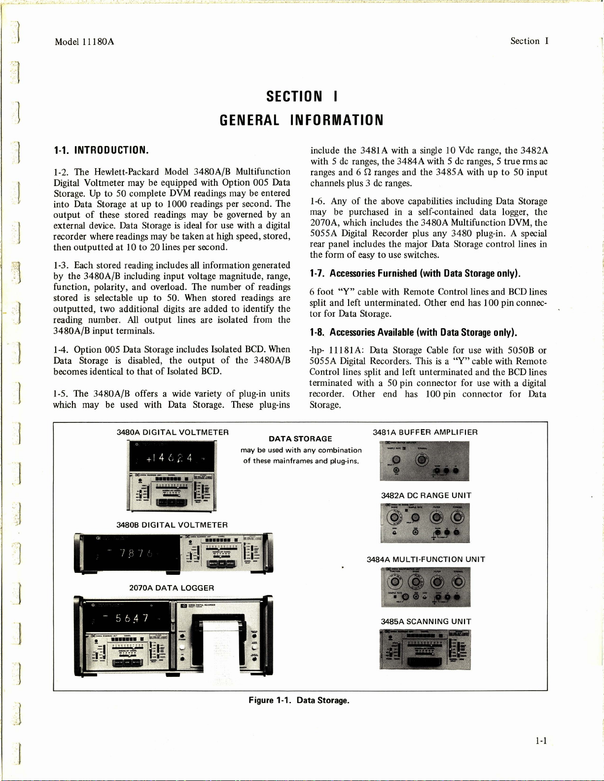
1-2.
The Hewlett-Packard
Digital Voltmeter may be equipped with
t
'r.'.
1
•.
.
:.·,;.
~.
.
..
' l
-
·~
·
,··
i
Storage.
into Data
output
external device. Data
recorder where readings may be taken at high speed, stored,
then outputted at
1-3. Each stored reading includes
by the 3480A/B including input voltage magnitude, range,
function, polarity, and overload. The number
stored
outputted, two additional digits are added
reading number.
3480A/B input terminals.
Up
to 50 complete
Storage at up to 1000 readings per second. The
of
these stored readings may be governed by an
10 to
is
selectable up to 50.
All
Model
Storage
20
lines per second.
output lines are isolated from the
3480A/B Multifunction
Option 005 Data
DVM
readings may be entered
is
ideal for use with a digital
all
information generated
of
When
stored readings are
to
identify the
readings
INFORMATION
include the 3481 A with a single
de
with 5
ranges and 6
channels plus 3
1-6.
may
2070A, which includes the 3480A Multifunction
5055A Digital Recorder plus any 3480 plug-in. A special
rear panel includes the major Data
the form
1-7.
6 foot
split and left unterminated.
tor for Data Storage.
1-8.
ranges, the 3484A with 5
S1
ranges and the 3485A with up
de
ranges.
Any
of
the above capabilities including Data Storage
be
purchased in a self-contained data logger, the
of
easy
to
use switches.
Accessories
"Y"
Accessories
Furnished
cable with Remote Control lines and
Available
(with
10 V
de
range, the 3482A
de
ranges, 5 true rms
Storage control lines in
(with
Data
Storage
Other end has 100 pin connec-
Data
Storage
only).
only).
to
50 input
DVM,
BCD
ac
the
lines
·1
..
''
J .
..
··
1
Option 005 Data Storage includes Isolated
1-4.
Data Storage
becomes identical to that
1-5. The 3480A/B offers a wide variety
which may be used with Data
·
l("
I "
is
disabled, the output
of
Isolated
3480A
DIGITAL
+I 4
1
~1-
.....
-
34808
DIGITAL
Ir'
' . I
2070A
VOLTMETER
(,
r 4
,
·
7 1'
VOLTMETER
DATA
LOGGER
BCD.
Storage. These plug-ins
(e:
..
-
BCD.
of
the 3480A/B
of
plug-in units
may
of
these mainframes
be
When
DATA
used
-hp-
11181 A: Data Storage Cable for use with 5050B or
is
5055A Digital Recorders. This
Control lines split and left unterminated and the
terminated with a
recorder.
Storage.
STORAGE
with
any
combination
and
Other end has 100 pin connector for Data
plug-ins.
50
pin connector for use with a digital
3481A
BUFFER
3482A
3484A
MULTI-FUNCTION
3485A
DC
SCANNING
a
AMPLIFIER
RANGE
"Y"
cable with Remote
UNIT
UNIT
UNIT
BCD
lines
J
J
~
J
.
..
..
Figure 1-1. Data Storage.
1-1
Page 8
·
.....
__
,.
:...
••
-.:.
......... • -.-·
t.
...
~·
•
.r
•· ·-..
Section I
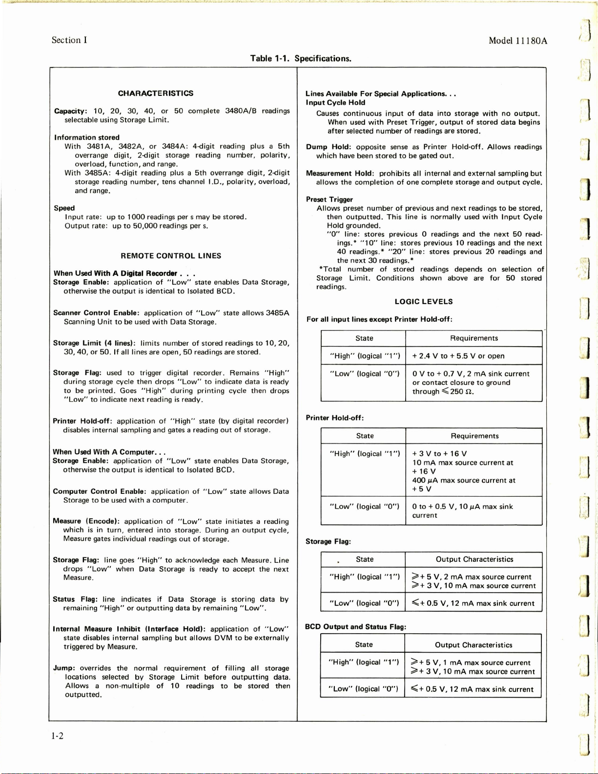
CHARACTERISTICS
Capacity:
Information
Speed
When Used With A Digital
Storage
otherwise
Scanner
Scanning
Storage
30,
10,
20,
30,
40,
selectable using Storage Limit.
With 3481 A,
With
Input
Output
stored
overrange digit, 2-digit storage reading
overload,
3485A
storage reading
and
rate: up
Enable:
Control
Limit
40,
3482A, or
function,
: 4-digit reading plus a
range.
rate: up
the
Unit
or
50.
number,
to
1000
to
REMOTE
application
output
Enable:
to
be
(4
lines): limits
If all lines
or
3484A
and
range.
tens
readings per s may
50,000
readings
CONTROL
Recorder
of
"Low"
is
identical
application
used
with
number
are
open,
50
complete
: 4-digit reading plus a
5th
channel l.D.,
per
. . .
state
to
Isolated BCD.
of
Data
Storage
of
50
readings
3480A/B
number,
overrange digit, 2-digit
polarity,
be
stored.
s.
LINES
enables
"Low"
state
.
stored
readings
are
Table 1-1. Specifications.
Lines Available
5th
20,
Input
Causes
Dump
which
Measurement
allows
Preset Trigger
Allows preset
*Total
Storage
readings.
For
all
Data
allows
stored
readings
polarity,
overload,
Storage,
3485A
to
10,
.
Cycle Hold
continuous
When used
after
selected
Hold:
opposite
have been
Hold:
the
completion
then
outputted.
Hold
grounded.
"O"
line:
ings.*
40
readings .*
the
next
number
Limit.
input
lines
State
"High"
(logical "1
For
Special
input
with
Preset Trigger,
number
sense as
stored
prohibits
number
of
This line
stores
previous 0 readings
"1
O"
line:
"20"
30
readings.*
of
stored
Conditions
LOGIC
except
Printer
") + 2.4 V to+
Applications
of
data
of
readings
Printer
to
be
gated
all internal
of
one
complete
previous
is
normally
stores
previous
line:
stores
readings
shown
LEVELS
Hold-off:
Model l l l
...
into
storage
with
output
of
are
stored
Hold-off. Allows readings
out
.
and
external
storage
and
next
readings
used
and
10
readings
previous
depends
above
Requirements
5.5 V or
stored
.
and
with
the
are
output
next
20
on
for
open
no
data
sampling
to
Input
and
readings
selection
output.
be
50
the
50
80A
begins
but
cycle.
stored,
Cycle
read-
next
and
stored
of
;l
1
'
rJ
"
'
:~
1
'
Storage
Printer
When
Storage
Computer
Measure
Storage
Status
Internal
Jump:
Flag: used
during
storage cycle
to
be
printed.
"Low"
to
Hold-off:
disables internal sampling
Used With A
Enable:
otherwise
Control
Storage
to
(Encode):
is
which
Measure gates individual readings
drops
Measure.
remaining
state
triggered
locations
Allows a
outputted
in
Flag: line goes
"Low"
Flag: line indicates if Data
Measure
disables internal sampling
by
overrides
to
Goes
indicate
application
Computer
application
the
output
Enable:
be
used
application
turn,
entered
when
"High"
or
Inhibit
Measure.
the
selected
non-multiple
.
trigger digital
then
"High"
next
reading
is
identical
with a computer.
"High"
Data
outputting
(Interface
normal
by
Storage
drops
"Low"
during
is
ready.
of
"High"
and
gates a reading
...
of
"Low"
to
application
of
"Low"
into
storage. During
out
to
acknowledge
Storage
data
but
requirement
Limit
of
10
recorder. Remains
to
indicate
printing
state
state
Isolated BCD.
of
of
is
ready
Storage
by
Hold):
allows DVM
readings
cycle
(by digital recorder)
out
enables
"Low"
state
state
initiates a reading
an
storage.
each Measure. Line
to
is
storing
remaining
application
of
filling all storage
before
outputting
to
data
of
storage.
Data
allows Data
output
accept
"Low"
to
be
be
stored
"High"
is
ready
then
drops
Storage,
cycle,
the
next
data
.
of
"Low"
externally
data.
by
then
Printer
Storage
BCD
Output
"Low"
Hold-off:
"High"
"Low"
Flag:
"High"
"Low"
and
"High"
"Low"
(logical
State
(logical "1
(logical
State
(logical "1
(logical
Status
State
(logical
(logical
"O")
0 V
or
through
")
+ 3 V
10
+
16
400
+5V
"0") 0 to+
current
")
;;;,,
+ 5 V, 2 mA max
;;;,,
+ 3 V,
"0")
<+
Flag:
"1")
;;;;.+
;;;,,
+ 3 V,
"0")
<+
to+
0.7 V, 2
contact
.:;;;
to+
mA
max
v
µA
max
0.5
V,
Output
10
0.5
V,
Output
5 V, 1 mA
10
0.5
V,
mA
closure
to
250
Requirements
16
source
source
mA
12
mA
12
ground
n.
V
current
current
10
µA
max
Characteristics
source
max
source
mA
max
Characteristics
max
source
max
source
mA
max
sink
sink
sink
current
at
at
sink
current
current
current
current
current
current
;J
r
1-2
Page 9
Model l l l 80A
•.
J •
••
•
:..
''
~·
•.
>'.•-
I.
,.
.•
·•
'Ill•
.i.,. { •
_.,
•• '
•
..._·,
~,.
•.
..
......
""•
....... 1
... , ..
1 ....
..
:r
Se
ction I
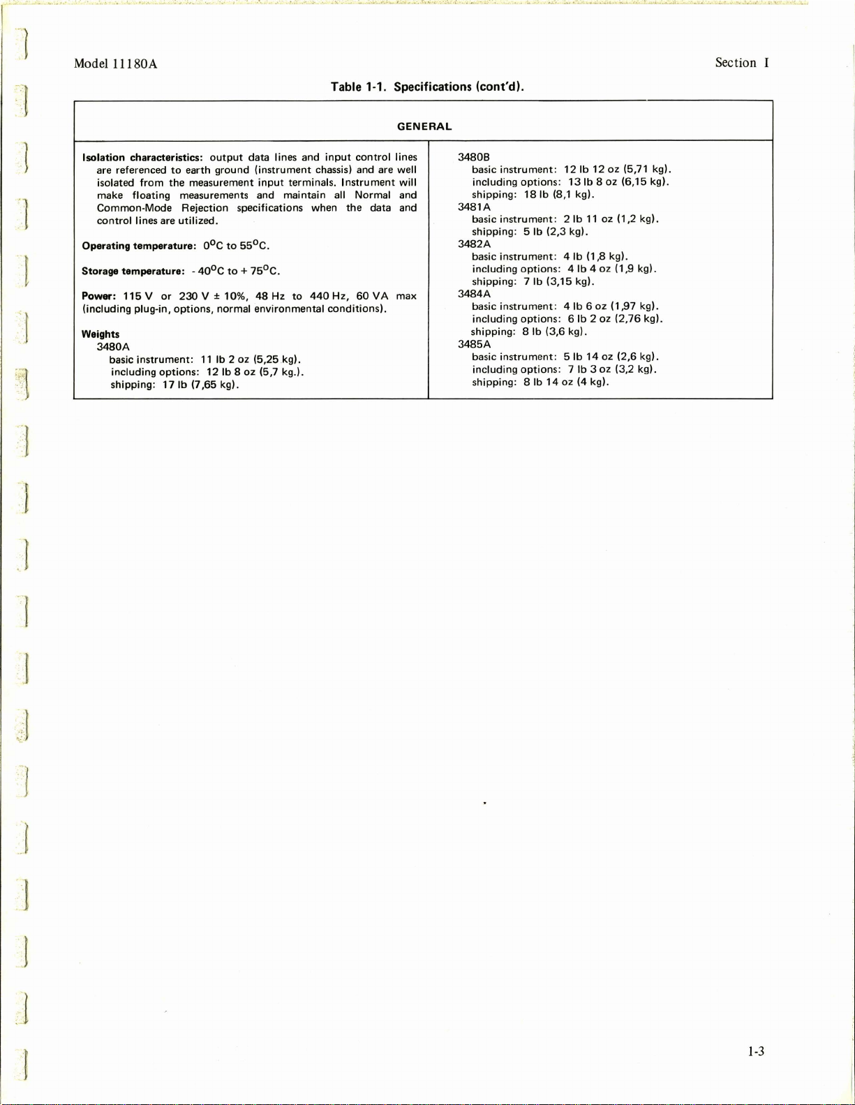
Table 1-1. Specifications (cont'd).
GENERAL
1
1
. ·1
I
Isolation
characteristics:
are referenced
isolated
make
floating
Common-Mode
control
Operating
Storage
temperature: -40°c
Power:
115 V or
(i
ncluding
Weights
3480A
basic
including
shipping:
to
from
earth
the
measurements and
Rejection
lines are
utilized
temperature:
230
plug-in,
options,
instrument:
options:
17
lb
output
ground
measurement
specifications when
.
0
o
c
to
55°C
to + 75°c
V ± 10%,
normal
11
lb
2 oz (5,25 kg).
12
lb
(7,65
8 oz (5 ,7 kg.).
kg) .
data lines and
(instrument
input
terminals.
maintain
.
.
48
Hz
to
envi
440
ronmental
input
control
lines
chassis) and are well
Instrument
all
Normal
the
Hz,
60
conditions)
will
and
data and
VA
max
.
34808
basic
instrument: 12
including
shipping:
3481A
basic
instrument
shipping
3482A
basic
instrument: 4 lb
i
ncluding
shipping
3484A
basic
instrument
including
shipping: 8 lb
3485A
basic
instrument: 5 lb
including
hipping
s
options: 13
18
lb
(8,1 kg) .
: 2
: 5
lb
(2,3
options
: 7
: 4
lb (3,
: 4
options
: 6
(3,6
options
lb
: 7
14
: 8
lb
lb
lb
11
kg).
(1,8 kg).
lb
15
kg).
lb 6 oz (1,
lb
kg) .
14
lb 3 oz
oz
(4
12
oz
(5,71 kg).
8 oz (6,
15
oz (1,2 kg).
4 oz (1,9 kg) .
97
(2,76
kg).
kg).
2 oz
oz (2,6 kg).
(3,2 kg).
kg).
kg).
.1
1-3
Page 10

"
••
!.
·•''·.,;
'Jo, • ;'
''-
~&•
•(·'·
....:..
··•
·•'-'·
~..,_
o.
..,
.o.."k.:
r.:. ~ -
......
, •
..,.,1.
. :.0
o"J.o."o'&•--'-',11.J.~·;
.,,....__
4
_.,.
..
--.._.
l 1
; ·
..
J '
r;'
,·
'
r
I
I
Page 11
"I
-l
~.
:· I
Model
l l l 80A
Section
II
,/·
1·
::-
..
·:
"
( r
·~-
i
]
·1
SECTION
IN
STALLATI
2-1.
INTRODUCTION.
2-
2.
This section contains installation and shipping infor-
mation for the
2-3.
INITIAL
2-4.
Each l l l 80A has been carefully inspected prior to
shipment and should
of
mars or scratches.
should
have occurred in transit or for deficiencies otherwise.
there
is
carrier;
attributable to shipping, refer to the statement
on the cover page
Section V to check the instrument performance. Refer to
Section I for the list
instrument.
2-5.
INSTALLATION
2-6. Contact
Office
regarding installation
3480A/B. (See Appendix B for office locations.)
2-7.
STORAGE
2-8.
See
Model
l l l 80A.
INSPECTION.
be
in perfect electrical order and free
To
confirm this, the instrument
be
inspected upon receipt for damage that might
damage due to shipping, file a claim with the
if
there are electrical or mechanical deficiencies not
of
warranty
of
your
CONNECTOR.
Table
3-1
this manual.
of
equipment supplied with the
OF
11180A
IMPORTANT
local Hewlett-Packard Sales and Service
of
for the
Use
the procedures
INTO
3480A/B.
the
11l80A
signal
arrangement at the
into
an
existing
If
of
II
0 N
Storage Connector.
2-9.
REPACKAGING
2-10.
If
the instrument
for service or repair, attach a tag to the instrument
describing the work to be accomplished and identifying the
owner and instrument. Identify the instrument by serial
number, model number and name in any correspondence.
you have any questions, contact your local Hewlett-Packard
Sales
and Service Office.
locations.
2-11.
If
the original shipping container
the instrument in the container with appropriate packing
meterial and
metal bands. A
nearest
2-12.
If
heavy carton or wooden box with an inner container.
the instrument with heavy paper or plastic and place
cardboard strips across the face for protection before
placing the instrument in the inner container.
material around
outer container
the container with "DELICATE INSTRUMENT," or
"FRAGILE".
-hp-
an
seal
Sales
-hp-
FOR
SHIPMENT.
is
to be shipped to Hewlett-Packard
See
Appendix B for office
is
to be used, place
the container
new
container may be purchased from your
and
Service
container
all
sides
of
well
with strong tape or metal bands.
well
with strong tape or
Office.
is
not to
the inner container, and
be
used, then use a
Use
If
Wrap
packing
seal
the
Mark
J
J
·1
2-1
Page 12

:1
~
l
]
,]
'
"'.
)
'J
' -
.:.J
JJ
Page 13
Model l l l 80A
Section III
r
J
<
"'·
1
..
. 'I
r
SECTION
OPERATING
3-1.
INTRODUCTION.
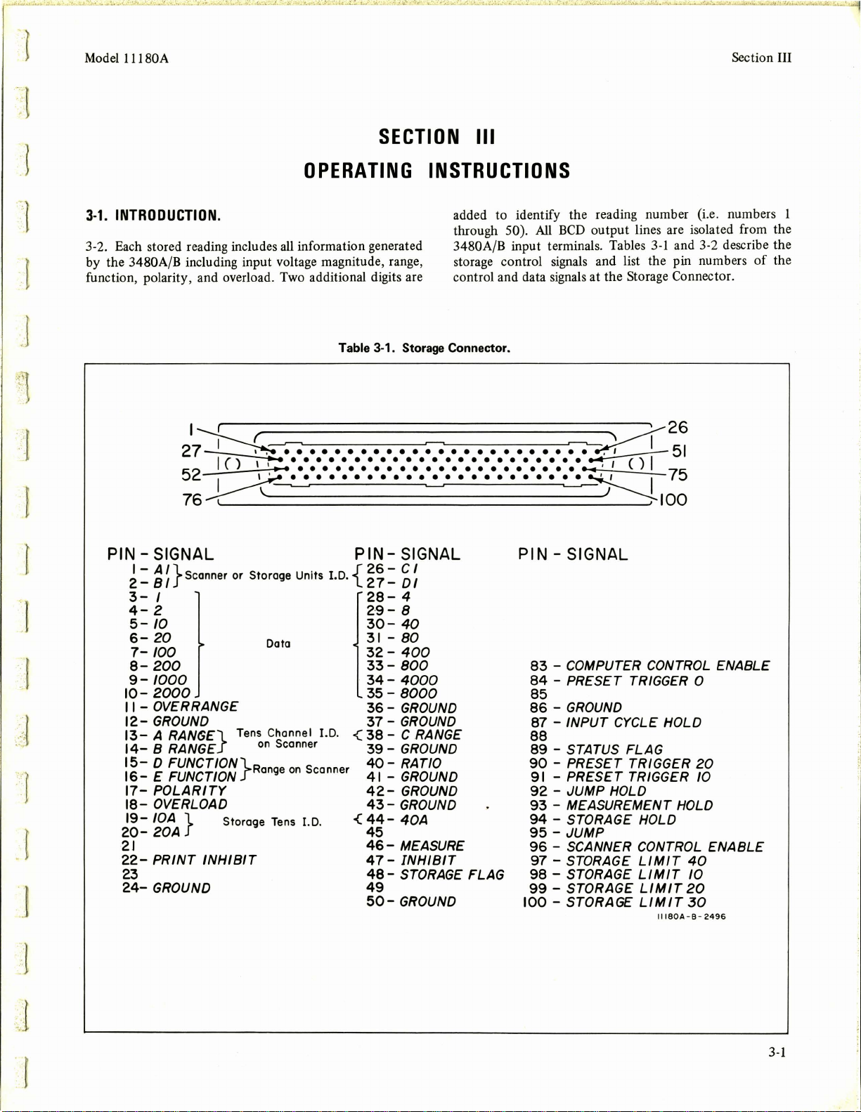
3-2. Each stored reading includes all information generated
by the
function, polarity, and overload. Two additional digits are
3480A/B including input voltage magnitude, range,
Table 3-1. Storage Connector.
d1~
I()
52
76~
........................
...........................
I I - • • • • • • • • • • • • • • • • • • • • • • - ' I
•••••••••••••••••••••••
Ill
INSTRUCTIONS
added to identify the reading number (i.e. numbers 1
through 50).
3480A/B input terminals. Tables
storage control signals and list the pin numbers
control and data signals at
All
BCD
output lines are isolated from the
3-1
and 3-2 describe the
the
Storage Connector.
~~~
~rc')'I
~100
75
of
the
r
I
.f
r
J
PIN - SIGNAL
I - A
I}
BI
_
2
3-
4-2
5-
6-
7-
8-
9 -
10-
11
- OVER RANGE
121314-
1516-
17-
1819-
20-
21
22-
23
24-
Scanner or Storage Units
I
10
20
100
200
1000
2000
GROUND
A
RAN(;E}
B RANGE
D
FUNCTION}
E FUNCTION
POLARITY
OVERLOAD
IOA
} Storage
20A
PRINT
GROUND
INHIBIT
PIN-
{
I.D.
Data
Tens Channel I.D. c(
on
Scanner
Range
on
Scanner
Tens
I.D. <
SIGNAL PIN - SIGNAL
26
- C I
_
DI
2 7
28-
4
2·
9-8
30-
40
31
-
80
32
-
400
33-
800
34
-
4000
35 -
8000
36
-
GROUND
37-
GROUND
38
- C RANGE
39
- GROUND
40-
RATIO
41
- GROUND
42-
GROUND
43-
GROUND
44-
40A
45
46
- MEASURE
47-
INHIBIT
48
- STORAGE FLAG
49
50-
GROUND
83
- COMPUTER CONTROL ENABLE
84
- PRESET TRIGGER 0
85
86
-
87 - INPUT CYCLE HOLD
88
89
- STATUS FLAG
90
- PRESET TRIGGER
91
- PRESET TRIGGER
92
- JUMP HOLD
93
- MEASUREMENT HOLD
94
- STORAGE HOLD
95
- JUMP
96
- SCANNER CONTROL
97
- STORAGE
98
- STORAGE
99
- STORAGE
100 - STORAGE
GROUND
LIMIT
LIMIT
LIMIT
LIMIT
II
180A-8-
20
10
ENABLE
40
10
20
30
2496
3-1
Page 14
Section III
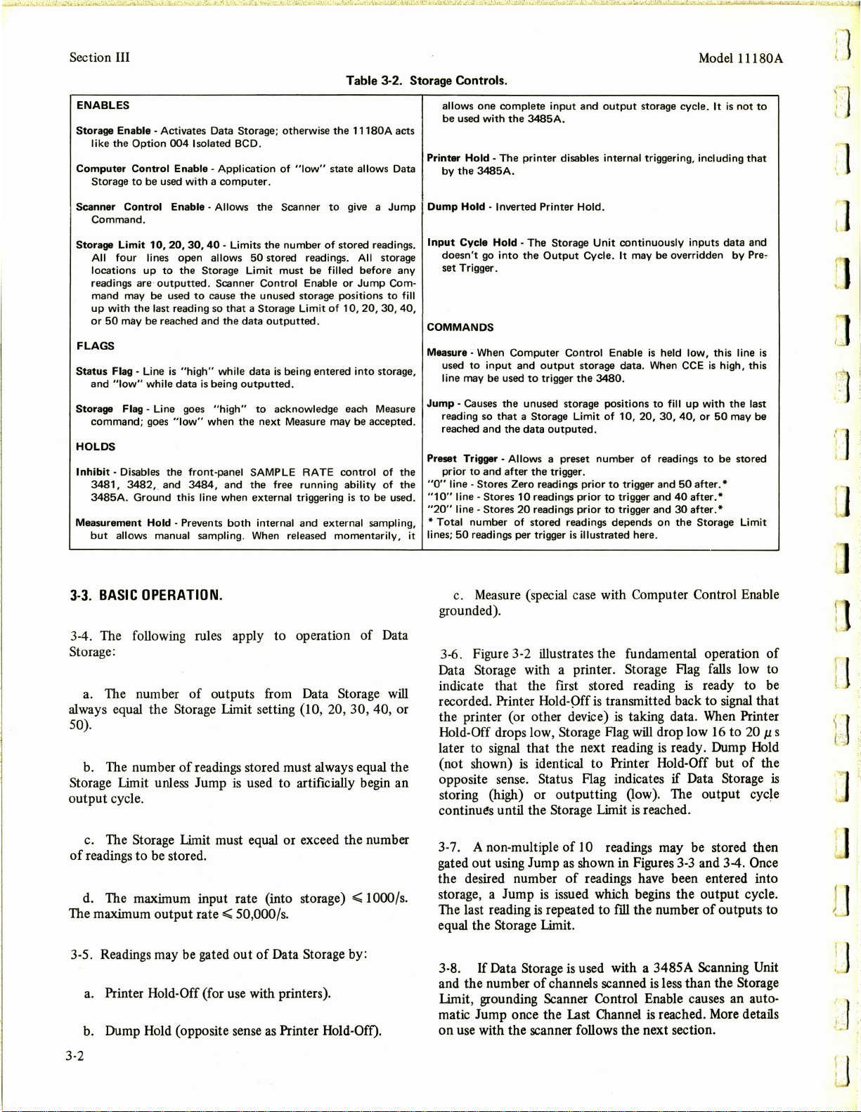
Table 3-2. Storage Controls.
Model
l l l 80A
':
l
'·
ENABLES
Storage Enable - Activates Data Storage; otherwise
like
the
Option
004
Isolated
Computer
Scanner
Storage Limit
FLAGS
Status
Storage Flag_ Line goes
HOLDS
Inhibit
Measurement
Control Enable - Application
Storage
to
be used
with a computer.
Control
Command.
All
four
locations
readings are
mand may
up
with
or
50
may be reached
Flag - Line
and
"low"
command;
- Disables
3481,
3482,
3485A
. Ground this line when external triggering
but
allows manual sampling. When released
Enable - Allows
10,
20,
30,
lines
open
up
to
the
outputted.
be
used
the
last reading so
is
"high"
while
data
goes
"low"
the
and
Hold - Prevents
front,panel SAMPLE RATE
3484,
BCD
.
of
the
Scanner
40
- Limits
the
allows
Storage Limit
Scanner Control Enable
to
cause
the
that
and
the
while
is
being
outputted
"high"
when
the
and
both
number
50
stored
must
unused storage positions
a Storage Limit
data
outputted.
data
is
being
to
acknowledge each Measure
next
Measure may be accepted. reading so
the
free running ability
internal
"low"
readings.
be filled
entered
.
and
the
11180A
acts
state
allows Data
to
give a
Jump
of
stored
readings.
All
storage
before
Jump
20,
to
be used.
any
Com-
to
fill
30,
40,
storage,
of
the
of
the
or
of
10,
into
control
is
external sampling,
momentarily,
allows
one
be
used with
Printer Hold -
by
the
Dump
Input
doesn't
set
COMMANDS
Measure·
used
line may
Jump
· Causes
reached
Preset Trigger - Allows a preset
prior
"O"
line -
"10"
line - Stores
"20"
line·
*Total
lines;
it
50
complete
the
3485A.
The
3485A.
Hold · Inverted Printer Hold.
Cycle Hold -
Trigger.
When
to
to
Stores
number
readings per trigger
printer
go
and
and
Stores
The
into
the
Output
Computer
input
and
be
that
output
used
to
trigger
the
unused storage positions
a Storage Limit
the
data
after
the
Zero readings prior
10
readings prior
20
readings prior
of
stored
input
and
output
storage cycle. It
disables internal triggering, including
Storage Unit
Control Enable
the
outputed.
trigger.
readings
is
continuously
Cycle. It may be overridden
storage
data.
3480.
of
10,
20,
number
illustrated here.
to
trigger
to
trigger
to
trigger
depends
of
inputs
is
held low, this line
When CCE
to
fill
up
30,
readings
and
and
and
on
with
40,
or
to
50
after.*
40
after.*
30
after.*
the
Storage Limit
is
is
not
data
by
high, this
the
50
may be
be
stored
to
that
and
Pre,
last
is
I.
··
1.
'
f
l
3-3.
BASIC
3-4. The following rules apply to operation
OPERATION.
of
Data
Storage:
a. The number
outputs from Data Storage
will
of
always equal the Storage Limit setting (10, 20, 30, 40, or
50).
b.
The number
Storage Limit unless Jump
of
readings stored must always equal the
is
used to artificially begin an
output cycle.
c.
The Storage Limit must equal or exceed the number
of
readings to be stored.
d.
The maximum input rate (into storage)
The maximum output
3-5. Readings may
a.
Printer Hold-Off (for
b.
Dump Hold (opposite sense
rate..;;;
be
gated out
50,000/s.
of
use
with printers).
as
Data Storage by:
Printer Hold-Off).
..;;;
1000/s.
c. Measure (special case with Computer Control Enable
grounded).
3-6
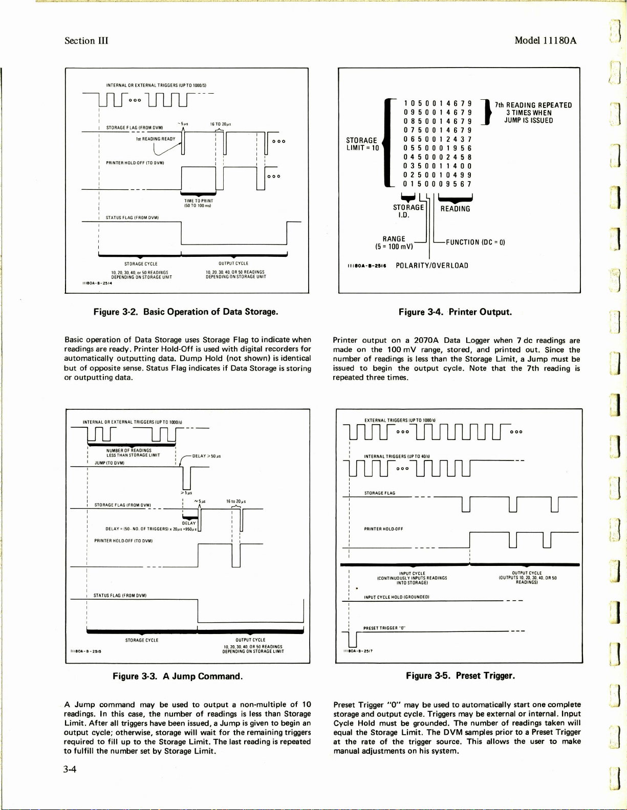
. Figure 3-2 illustrates the fundamental operation
of
Data Storage with a printer. Storage Flag falls low to
indicate that the first stored reading
recorded. Printer Hold-Off
the printer (or other device)
Hold-Off drops low, Storage Flag
is
transmitted back to signal that
is
taking data.
will
later to signal that the next reading
(not shown)
is
identical to Printer Hold-Off but
opposite sense. Status Flag indicates
is
ready to
When
be
Printer
drop low 16 to 20 µ s
is
ready. Dump Hold
of
the
if
Data Storage
storing (high) or outputting (low). The output cycle
continues until the Storage Limit
3-
7.
A non-multiple
gated out using Jump
the desired number
storage, a Jump
The last reading
of
10 readings may be stored then
as
shown in Figures
of
readings have been entered into
is
issued which begins the output cycle.
is
repeated to fill the number
is
reached.
3-3
and 3-4. Once
of
outputs to
equal the Storage Limit.
If
3-8.
Data Storage
and the number
is
used with a 3485A Scanning Unit
of
channels scanned
is
less than the Storage
Limit, grounding Scanner Control Enable causes an auto-
matic Jump once the
Last
Channel
is
reached.
More
details
on use with the scanner follows the next section.
ll
is
3-2
Page 15
.l
..
"•
'•
:1
r
Model 11180A
3-9. Preset Trigger may be used
Triggering
internally. When any
grounded, the
dumped
3-5. The sum
"X"
is
continuous either from an external source or
"X"
out
plus the next
of
equals ''O",
of
the three Preset Trigger lines are
number
"X"
and "Y" equals
"1
O"
, or
Cycle Hold must be grounded in this mode
Input Cycle Hold causes readings
to
begin an
of
previously stored reading
"Y"
readings
the
"20"
previous readings. Input
output
as
shown in Figure
Storage Limit, and
of
to
be continuously
cycle.
operation.
inputted without any output unless given a Preset Trigger.
3-10. Grounding Measurement Hold stops
both
from external and internal trigger sources.
inhibits
Measurement Hold momentarily
causes Data Storage
both
input and output storage cycles. Ungrounding
as
shown in Figure 3-6
to
cycle through one complete input
and output cycle automatically. Triggers equal
all
sampling
It
also
to
the
Storage Limit are counted automatically.
3-11. Grounding
COMPUTER CONTROL ENABLE allows
one line, MEASURE, to be used to gate readings into and
Section III
out
of
storage
PRINTER
readings out. The nature
to
is
acknowledge each MEASURE for both storage and
output
cycles. This mode
computer systems or systems with a limited number
as
shown in Figure 3-7.
DUMP
HOLD or
HOLD-OFF are no longer needed to gate
of
STORAGE FLAG also changes
of
operation
was
designed for
of
control lines. The timing for Data Storage running at a
50 kHz
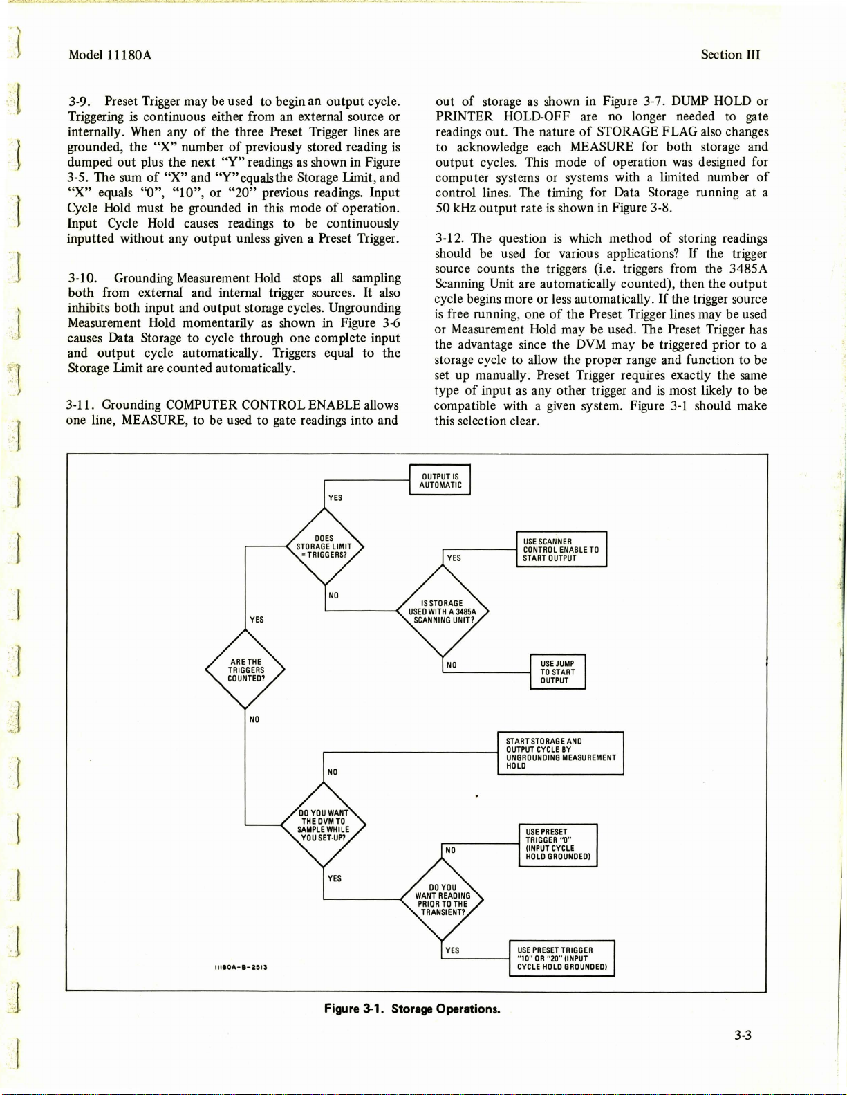
3-12. The question is which method
should be used for various applications?
source counts the triggers (i.
Scanni
cycle begins more or less automatically.
is
output
rate
is
shown in Figure 3-8.
of
e.
triggers from the 3485A
ng
Unit are automatically counted), then the output
If
the trigger source
free running, one
of
the Preset Trigger lines may be used
storing readings
If
the trigger
or Measurement Hold may be used. The Preset Trigger has
DVM
the advantage since the
may be triggered prior to a
storage cycle to allow the proper range and function to be
set up manually. Preset Trigger requires exactly the same
type
of
input as any other trigger and
compatible with a given system. Figure
is
most likely
3-1
should make
to
be
this selection clear.
1
J
. 1
'.
'f
.·:
l
"'""'•
r
YES
NO
OUTPUT
IS
AUTOMATIC
~-----1
.---------f
USE
SCANNER
CONTROL
START
OUTPUT
USE
JUMP
TO
START
OUTPUT
START
STORAGE
OUTPUT
CYCLE
UNGROUNDING
HOLD
USE
PRESET
TRIGGER
(INPUT
CYCLE
HOLD
GROUNDED)
ENABLE
TO
ANO
BY
MEASUREMENT
"O"
llllOA-l-2Sl3
~----I
Figure 3-1. Storage Operations.
USE
PRESET
"10"
CYCLE
OR
HOLD
TRIGGER
"20"
(INPUT
GROUNDED)
3-3
Page 16
Section III
INTERNAL
OR
EXTERNAL
TRIGGERS
Model l 1180A
I'
J
(UP
TO
1000/S)
l'.
STORAGE
FLAG
(FROM
~~~~~-
PRINTER
DVM)
-~~~--1·r--~~--"'-"1~~~~~
HOLD-OFF
(TO
~:-.--iU
STATUS
FLAG
(FROM
OVMI
STORAGE
10, 20,
DEPENDING
l
lll!IOA-8-251
..
Figure 3-2. Basic Operation
Basic
operation
readings are ready . Printer
automatically
but
of
opposite
or
outputting
CYCLE
30,40,or
50
READINGS
ON STORAGE
of
Data Storage uses Storage Flag
outputting
sense.
Status
data.
16TO
20,..s
DVM)
UNIT
Hold-Off
data.
Dump
I
I
TIME
TO PRINT
(50TO 100ms)
OUTPUT
10.20.30,40,
OR
DEPENDING
ON
of
Data Storage.
is
used with digital recorders for
Hold
(not
Flag indicates if Data Storage
CYCLE
50
READINGS
STORAGE
shown)
to
0
00
UNIT
indicate when
is
identical
is
storing
STORAGE
LIMIT=
11110&-1-2011
Printer
made
on
number
issued
repeated
10
output
the
of
to
begin
three
1050014679
0950014679
0850014679
0750014679
0650012437
0550001956
0450002458
0350011400
0250010499
0150009567
POLARITY/OVERLOAD
Figure 3-4. Printer Output.
on a 2070A
100
readings
the
times.
mV range,
is
output
Data Logger when 7
stored,
less
than
the
cycle. Note
7th
READING
3
}
and
TIMES
JUMP
printed
Storage Limit, a
that
the
REPEATED
WHEN
IS
ISSUED
de
readings are
out.
Since
Jump
7th
reading
the
must be
.]
is
J
INTERNAL
OR
EXTERNAL
TRIGGERS
-i
llJIOA-
n I
~
JUMP
STORAGE
PRINTER HOLO·OFF (
1
STATUS
8-2515
---uu----
0 :
NUMBER
OF
READINGS
LESS
THAN
STORAGE
!FROM
(FROM
STORAGE
DVM)
TO
OV~I-
DVMl
UMIT DELAY
CYCLE
(TO
DVM)
FLAG
FLAG
Figure 3-3. A
A
Jump
readings. In this case,
command
Limit.
After
output
cycle; otherwise, storage will wait
required
to
fulfill
to
the
fill
may
the
all triggers have been issued, a
up
to
set
the
by
number
(UP
TO
1000/s)
1
_
___r--u--
Jump
be
used
number
Storage Limit.
;;.
50
µs
DEPENDING
Command.
to
output
of
readings
Jump
for
The
I
I
OUTPUT
CYCLE
10
. 20,30.40.
OR
50
READINGS
ON
STORAGE
a non-multiple
is
less
than
is
given
the
remaining triggers
last reading
LIMIT
to
is
Storage Limit.
of
10
Storage
begin an
repeated
EXTERNAL
TRIGGERS
WP
1IULJ
I
INTERNAL
1IUlf
STORAGE
PRINTER
INPUT
PRESET
l
lllOA·B-2!117
ooo
TRIGGERS
ooo
FLAG
HOLO·OFF
INPUT
ICON
TINUOUSL Y INPUTS
INTO
CYCLE
HOLD
TRIGGER
"O"
1JlJ1J1Jliljo
(UP
lILilJu---
CYCLE
STORAG
(GROUNOEOJ
Figure 3-5. Preset Trigger.
Preset Trigger "O" may
storage
and
output
Cycle Hold
equal
the
at
the
rate
manual
adjustments
Storage Limit.
cycle. Triggers may
must
be grounded.
of
the
trigger source. This allows
on
TO
1000/sl
TO 40/
s)
READINGS
E!
be
used
The
DVM samples prior
his
system.
to
automatically
be
The
number
(OUTPUTS 10,
external
of
oo
OUTPUT
CYCLE
20. 30.40.
OR
READINGS!
start
one
complete
or
internal.
readings
the
taken
to
a Preset Trigger
user
to
50
Input
will
make
'.
l]
:J
I
I
(.
'·
1
h
(J
I·
'.
J
3-4
u
Page 17
J
.
.(
---.
_·":
~
1
r
\
Model l l l 80A
1
1JiJCF:•::
I
'
tnJ[f:·:
STORAGE
PRINTER
110,20,30,40,
AUTOMATICALLY
>
5~1
MEASUREMENT
ONE
INPUT
llllOA-1-2'
11
1JiJulJLrlrooo
OR
·
~lil_r----
FLAG (FROM
OVM)
HOLD·OFF
ITO
OVM
)
INPUT
CYCLE
0R
50TRIGGERS
ACCEPTED
I
HOLD
UNHIBITS
OUTPUT
CYCLE
SAMPLING
TO
TAKE
AND
TIME
TO
BUT ALL
PLACE)
PRIN
T
OWS
OUTPUT
CYCLE
MEASURE
I I I
IOA-8-2527
17T022µs
I
I
16
TO
•
20µs
Section III
v
1
TO
2µs
J
r
.j
J
J
l
.. :·I
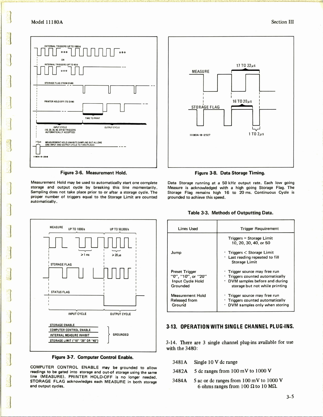
Figure 3-6. Measurement Hold.
Measurement
storage and
Sampling does
proper number
automatically
Hold
output
not
of
.
MEASURE
~~~~~~~~~~~~,--------"----.
flfiJ
I I
1
STATUS
FLAG
STORAGE
COMPUTER
INTERNAL
STORAGE
Figure 3-7. Computer Control Enable.
COMPUTER
readings
line
(MEASURE). PRINTER
STORAGE
and
output
to
be
FLAG
cycles .
CONTROL
gated
may be
used
1000
to
by
prior
/s
;>
1
ms
cycle
take place
triggers equal
UP
TO
UuulJ
INPUT
CYCLE
ENABLE
CONTROL
ENABLE
MEASURE
INHIBIT
LIMIT ("10" "20"
into
acknowledges each
OR
"40"1
ENABLE
storage and
HOLD-OFF
automatically
breaking this line
to
or
to
the Storage
start one complete
after a storage cycle. The
UP
TO 50,
..
20µs
momentarily.
Limit
000
/s
are counted
I
~____.I
OUTPUT
CYCLE
}
'"""""'"
may be grounded
out-of
storage using the
is
MEASURE
no longer needed .
in
both
to
storage
allow
same
Figure 3-8. Data Storage Timing.
Data Storage running
Measure is
Storage Flag remains high
grounded
acknowledged
to
achieve this speed.
Table 3-3. Methods
Lines Used
Jump
Preset Trigger
"O",
"1
O",
Input
Grounded
Measurement
Released
Ground
3-13.
or "20"
Cycle
Hold
from
OPERATION
Hold
at a 50
with
WITH
kHz
output
a high going Storage Flag. The
16
to
of
Outputting Data.
Triggers
10,20,30,40,orSO
Triggers < Storage
Last reading repeated
Storage
Trigger source may free run
Triggers counted
DVM
storage
Trigger source may free run
Triggers counted
DVM
SINGLE
rate. Each
20 ms. Continuous Cycle
Trigger Requirement
= Storage
Limit
samples before and
but
not
samples
only
CHANNEL
low
Limit
Limit
to
fill
automatically
during
while
printing
automatically
when storing
PLUG-INS.
going
3-14. There are 3 single channel plug-ins available for use
with the
3480:
3481A Single 10 V de range
3482A 5
3484A 5
de
ranges from 100 m V
ac
or de ranges from I 00 m V
6 ohms ranges from I 00
to
1000 V
il
to
to
I 000 V
I 0 Mil.
is
3-5
Page 18
Section
III
Model
l l l 80A
3-15.
In
either
de
or ohms, these plug-ins are able to make
1000 correct readings/s. Within 1 ms, the 3480
is
able to
respond to a full-scale change and digitize. These single
channel plug-ins combined with the
3480 main frame are
able to act like a low cost, 1 kHz A-to-D converter. Data
Storage allows up to 50 readings taken at up to 1000/s to
be
stored and printed.
3-16.
As
shown in Table 3-4, these plug-ins contain their
own sample-rate oscillator able to take from 1 reading/s up
to approximately
40 readings/s. These plug-ins must
be
externally triggered (throup,h the main frame) to achieve
higher sampling rates.
Table 3-4. Maximum Triggering Rates.
Internal External
3481A
3482A
3484A
*Variable
front
panel sample-rate
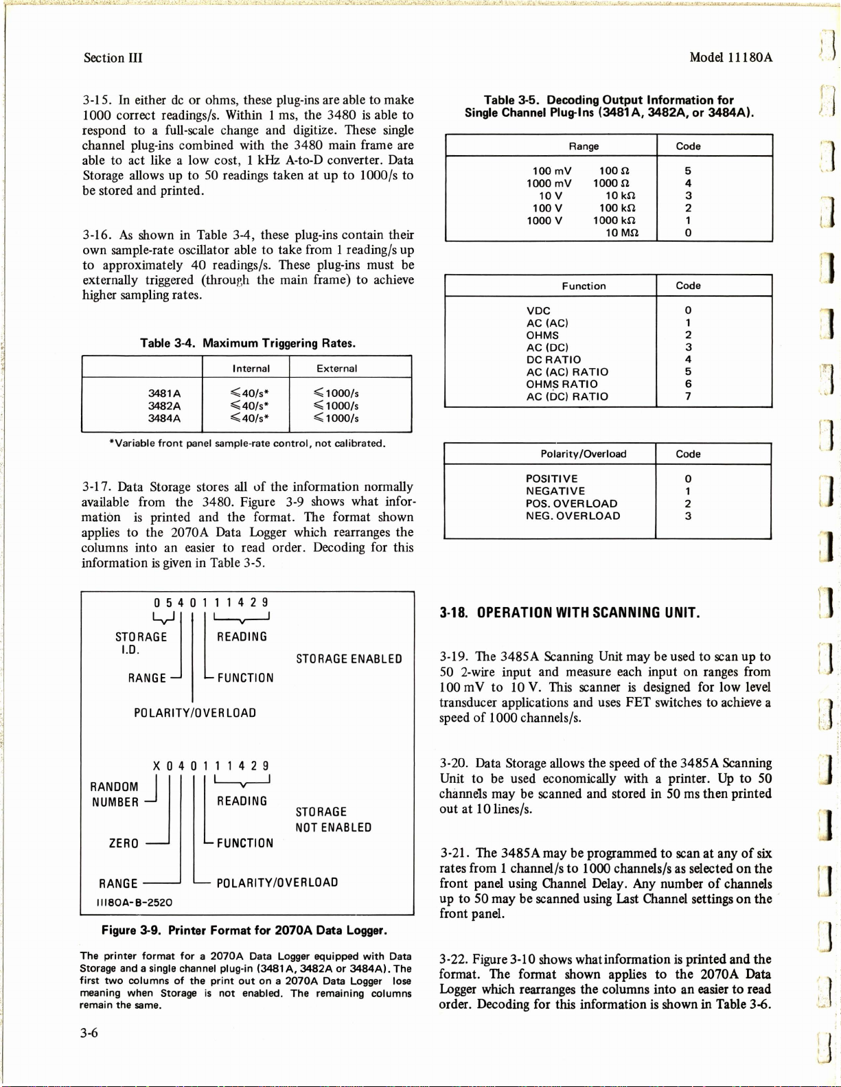
3-17. Data Storage stores
available from the
mation
is
printed and the format. The format shown
applies to the
3480. Figure 3-9 shows what infor-
2070A Data
<(40/s*
<(40/s*
<(40/s*
all
of
the information normally
Logger
<( 1000/s
<( 1000/s
<( 1000/s
control,
not
calibrated.
which rearranges the
columns into an easier to read order. Decoding for this
information
is
given
in Table 3-5.
Table 3-5. Decoding
Single Channel Plug-Ins (3481
100mV
1000
mV
10V
100
v
1000
v
VDC
AC (AC) 1
OHMS
AC (DC)
DC
RATIO
AC (AC)
OHMS
AC (DC)
Polarity /Overload
POSITIVE
NEGATIVE
POS.
OVER
NEG.
OVERLOAD
Output
Range Code
1oon
1ooon
10
100
1000
10Mn
Function
RATIO
RATIO
RATIO
LOAD
Information
A,
3482A,
kn
kn
kn
5
4
3
2
1
0
Code
0
2
3
4
5
6
7
Code
0
1
2
3
or
3484A).
for
ri·.
I .
I .
Tl:
' .
"
1".
J
. .
I .
0 5 4 0 1 1 1 4 2 9
1
STORA~J
l.D.
RANGE
POLARITY/OVER
l1REA~ING
STORAGE
FUNCTION
LOAD
x 0 4 0 1 1 1 4 2 9
RANDOM]
NUMBER
ZERO
RANGE
lllSOA-B-2520
Figure 3-9. Printer Format
The
printer
two
format
single channel plug-in (3481
columns
same
.
Storage and a
first
meaning when Storage
remain the
l~
READING
FUNCTION
POLARITY
for a 2070A
of
the
print
is
not
STORAGE
NOT
/OVERLOAD
for
2070A Data Logger.
Data Logger equipped
A,
out
on a
enabled. The remaining columns
3482A
2070A
ENABLED
ENABLED
with
3484Al.
Data
The
or
Data Logger lose
3-18.
OPERATION
WITH
SCANNING
UNIT.
3-19. The 3485A Scanning Unit may be used to scan up to
50 2-wire input and measure each input on ranges from
100 m V to 10 V. This scanner is designed for low level
transducer applications and uses FET switches to achieve a
speed
of
1000 channels/s.
3-20. Data Storage allows the speed
Unit to
be
used economically with a printer.
of
the 3485A Scanning
Up
to 50
channels may be scanned and stored in 50 ms then printed
out at
10 lines/s.
3-21. The 3485A may be programmed to scan at any
rates from 1 channel/s to 1000 channels/s as selected
front panel using Channel Delay. Any number
up to
50 may be scanned using
Last
Channel settings
of
channels
of
on
on
six
the
the
front panel.
3-22. Figure
format. The format shown applies to the
Logger
order. Decoding for this information
3-10 shows whatinformation
is
printed and the
2070A Data
which rearranges the columns into an easier to read
is
shown in Table 3-6.
:1
I .
' }
/.:
J.
3-6
Page 19

Model l l l 80A
STD
1 5 1
RAGE
ENABLED
204068
PROGR
AM INITIA
TE (TO SCAN
NER
Section III
)
. I
J
TENS
POLARITY
OVERLOAD
STORAGE
CHANNEL
l.D.
L.,JJ
1.0
.
AND
STORAGE
~
l
RANGE
NOT
ENABLED
x 5 1 1 2 0 4 0 6 8
RANDOM
NUMBER
JI
CHANNEL
BACKWARDS
II
llOA-1-2521
1.0
.
POLARITY
OVERLOAD
Figure 3-10. The Printer Format.
~
l
RANGE
AND
17
TRIGGER
AST CHANNEL"'
AG (FROM
OFF
(TO OVM)
BLE (GROUNDED
LIMIT "20"
LINE (GROUNDED
S
OVM)
17
)
)
)
Used
L
ST
______;_.,;..__;___~u
11180A-B-25
ORAGE FL
PRINTE
R HOLD-
STORA
GE ENA
SCANNER ENABLE (GROUNDED
S
TORAGE
22
Figure 3-11. Data Storage
Scanning Unit.
Data
Storage
non-multiple
Scanner
storage
Outputting
of
20
readings.
Enable
jumps
begins
used
of
ahead
10
must
with
with
channels
be
grounded.
to
the
the
the
is·
Storage
17th
3485A
scanned,
When Chan:iel
Limit
reading
JUMP FROM
SCA
I
c::
ST
~CYC
5µs 16TO 20µs
/\
·
..-----~u-0
ORA
GE STAR
LE
r"'i
NNER
TS
OUTPUT
LJooo
20 REA
DING GATED OUT
STORAGE
LIMIT" 20
with
the
3485A
Scanning
in
setting
repeated 3 times
this
case,
, in
Unit
17
17
this
channels
is
for a total
TO
0 0
where
reached,
case 20.
a
.
..
·r
.·
.r
1
]
3-23. When
equal
cause Data Storage
the
number
the
Storage Limit, grounding Storage Enable will
to
of
jump
channels
to
an
output
to
be scanned does
cycle after
the
not
last
channel has been scanned as shown in Figure 3-11. The
reading
Limit
on
the last channel
is
reached as shown in
is
repeated until the Storage
the
printout in Figure 3-12.
Table 3-6.
Decoding
Output
Information for
Range
100
1000
lOV
Polarity/Overload
POSITIVE
NEGATIVE
POSITIVE
NEGATIVE
OVERLOAD
the
mV
mV
OVERLOAD
3485A Scanning Unit.
Code
0
1
2
Code
0
1
2
3
The
3485A
Logger
Channel =
scanner
Note
that
reverts
l.D.
for
17).
may
the
to
17th
READING
REPEATED
3
TIMES
LAST
CHANNEL/
TENSCHANNELl
lllSOA-B-2523
Figure 3-12.
Scann
ing
scanning
Scanner
issue a
Jump
17th reading
zero
during
2
000112
l 9 0 0 1 1 2 3 4 1
{
1 8 0 0 1 1 2 3 4 1
1710112
1 6 1 0 1 0 9 7 7 4
1510100167
1410111245
1310009467
1210201140
1 l 1 0 1 0 1 4 2 l
1010210456
090101
0801001875
0700200509
0600111121
0501110025
0401101125
0301201489
0200001232
0100101379
STOR::J
l.D.
.D.
POLARITY /OVER
Jump
Unit
used
17
Enable
the
with
channels
must
when
17
is
repeated 3 times. The
repeated
3
41
3
41
1
992
L
READING
RANGE
LOAD
Printout.
Storage
(Storage
be
grounded
channels
readings.
in a
Limit=
have
2070A
so
been
Tens
Data
20;
that
scanned.
Channel
Last
the
3-7
Page 20

Section III
3-24. The 3485A may
programmed to take bursts
of
be
readings across the same channels, store each burst then
all
output
be divisible into the
readings. The number
Storage Limit an integral number
times. For example, 2 bursts
Limit = 20. Table
A timing example
3-
7 illustrates the different combinations.
is
shown in Figure 3-13 with a printout
of
channels scanned must
of
10 channels with Storage
of
in Figure 3-14.
Table 3-7.
3485A/Data
Last Channel Storage
Storage Operation for Bursts of Readings.
3485A
Setting Setting
5
5
5
5
5
10
10
10
10
25
2
2
2
2
2
3
4
Limit
10
20
30
40
50
20
30
40
50
50
10
20
30
40
50
30
40
Number
of
Bursts
2
4
6
8
10
2
3
4
5
2
5
10
15
20
25
10
10
PROGRAM
PROGRAM
llllOA-1-1525
2ND
25
CHANNELS
INITIATE
IST
25
CHANNELS
INITIATE
BURST
--
BURST
--
OF
Of
5020604328
4 9 2 0 6 0 4 5 0 9
4820604292
4 7 2 0 6 0 4 0 5 8
4 6 2 0 3 0 5 6 4 9
4 5 2 0 2 0 4
4410204519
4310204353
4210604132
4110701062
4010701753
3910701713
3810301673
3710301741
3610301658
3 5 1 0 7 0 1 7 7 1
3400701679
3300700679
3200300319
3100305199
3000704653
2900701459
2800704120
2 1 0 0 1 0 1 5 0 0
2600301010
2520601
2420601512
2320601621
2220601482
2120201440
2020205572
1910205032
1810205160
1 7 1 0 6 0 4 1 7 1
1 6 1 0 6 0 5 1 7 0
1510605060
1410605681
I 3 1 0 2 0 5 4 9 0
12
1110204409
1 0 1 0 6 0 I 0 4 0
0900601190
0800604070
0700601180
0600201072
0500201632
0400201392
0300601271
0200600033
0100601423
5.
510
10204180
8
Model
1 l l 80A
IJ
]
IHURNALTlllGGUlfWITHINSCAfOIE;:.Rl-------------
l.J1•IURST
I
OCHA
NNEL
S
INO. JTHROUGHN0.10)
"'"1
~-------~
STORAGEflAG
(fROMDVM)
PlllliTEAHOLO·OHITOOVMI
_____
INl'UT
CYCLE,21
-~"'~"':GE~l~'"'-'-'
Data Storage may be used
the
3485A
stored. Separate Program
to
start
may be given its
"20"
··
"-20
·
__
}GROUNDED
Figure 3-13. Burst Operation.
to
Scanning
the
input
Unit.
scanning sequence. Ready indicates when
next
Program
and
output
LJ
2ndBURST
!OCHANNHS
(
NQ.lTHAOUG
HN0.101
n I
~------~·
URSTSOF10CHANNEl$
to
store bursts
In
this
case,
Initiate
commands are given
Initiate.
20
readings.
two
The
of
bursts
Storage
f--OUT
PUT
-
lflrl0···
___,11.flf-··
O
UTl'UTCYClE
2011f
AOI
NGS
scanned readings
of
10
to
Limit
from
channels are
the scanner
the
scanner
is
set
to
Figure 3-14. Burst Printout.
The
print-out
channels then
Channel=
burst.
3-25.
on a
2070A
is
shown
all
50
the
10's Channel
25).
outputting
Note
how
SAMPLE-ANO-HOLD
for
scanning
readings (Storage
IMPROVES
l.D.
DIGITIZING.
two
Limit = 50;
helps
identify
bursts
of
Last
each
25
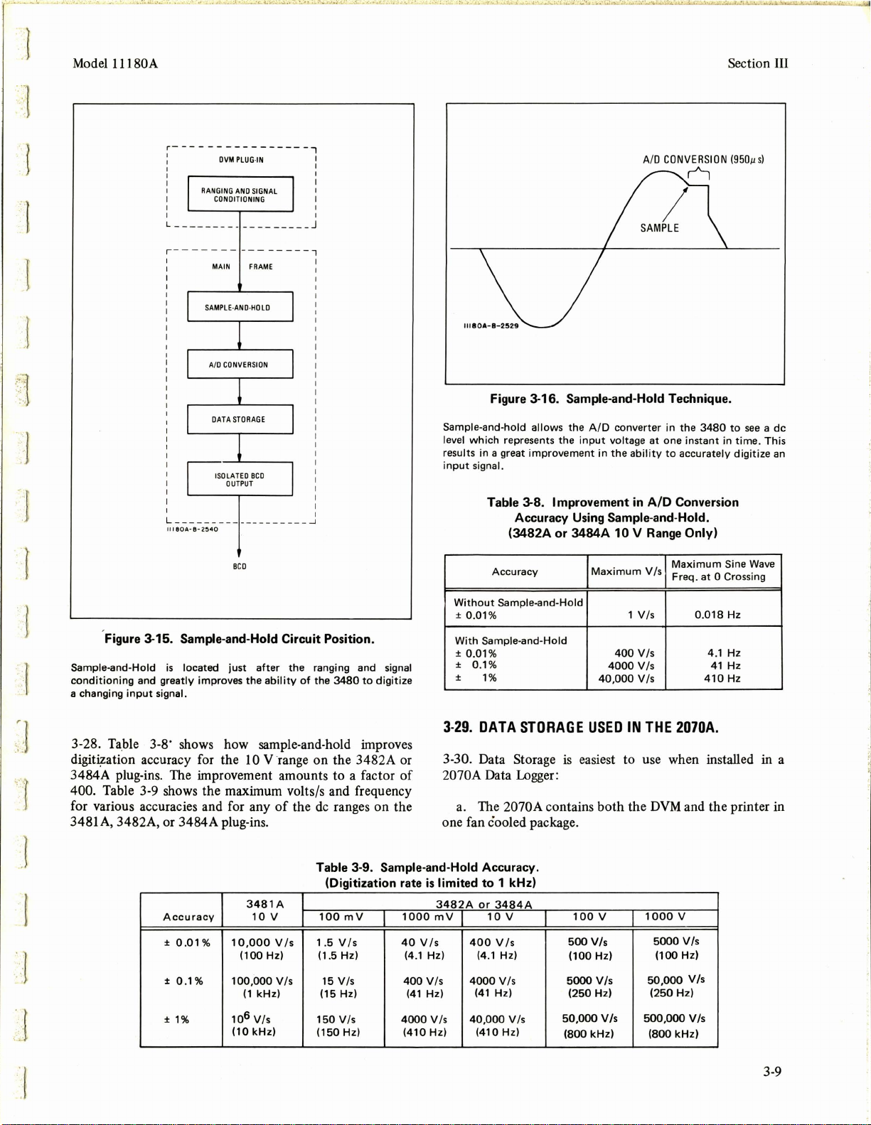
3-26. The successive approximation technique used for
A/D conversion in the 3480
is
limited in its ability to
accurately digitize a changing input voltage. This limit
equal to
range, 1 V /s. This translates to a 0.018
10%
of
the full-scale voltage range/s or on the 10 V
Hz
sine
wave
digitized to ± 0.01 % accuracy.
3-27. Sample-and-hold may
frame
as
shown in Figure 3-15. Sample-and-hold takes the
changing input
signal
conditioned by the plug-in and holds
be
added to the 3480 main
it just prior to A/D conversion. The A/D converter,
therefore , looks at a
level at the time
de
of
the sample
level which represents the
as
shown in Figure 3-16.
signal
J
:J
is
3-8
Page 21
1
·1
Model l l l 80A
r----------------1
:
I I
I I
I I
I
I
I I
I I
L
_____
DVM
RANGING
CONDITIONING
____
PLUG-IN
AND
SIGNAL
_________
r---------------,
:
I
I I
L------
111BOA·8-2
MAIN
FRAME
SAMPLE·AND·HDLD
A/0
CONVERSION
DATA
STORAGE
ISO
LA
TEO
BCD
OUTPUT
---
------
540
----
I
J
I
~
Figure 3-16. Sample-and-Hold Technique.
Sample-and-hold allows the
level
which
represents the
results in a great
input
signal.
improvement
Table 3-8. Improvement
Accuracy
(3482A
or
Using
3484A
A/D
converter in the
input
voltage at one instant in
in
the
ability
in
A/D
Sample-and-Hold.
10 V Range
3480
to
accurately
Conversion
Only)
Section III
to
see
a de
time.
This
digitize
an
l
..
'·1
·'·
: .-1
BCD
Figure 3-15. Sample-and-Hold Circuit Position.
Sample-and-Hold
conditioning
a changing
is
and greatly improves the
input
located
signal.
just
after
the ranging and signal
ability
of
the
3480
to
digitize
3-28. Table 3-8· shows how sample-and-hold improves
digit~ation
3484A plug-ins. The improvement amounts to a factor
accuracy for the 10 V range on the 3482A or
of
400. Table 3-9 shows the maximum volts/s and frequency
of
the
de
for various accuracies and for any
3481
A,
3482A, or 3484A plug-ins.
Accuracy
±
0.01
%
± 0.1 % 100,000 Vis
3481A
10
10,000
(100 Hz)
(1
kHz) (15 Hz)
v
Vis
ranges on the
Table 3-9. Sample-and-Hold Accuracy.
(Digitization rate
100
mV
1 .5
Vis
(1
.5 Hz) (4.1 Hz)
15 Vis
1000
40
400
Accuracy
Without
With Sample-and-Hold
± 0.Q1%
± 0.
±
3-29.
Sample-and-Hold
± 0.01%
1%
1%
DATA
3-30. Data Storage
2070A Data Logger:
a. The
one fan cooled package.
is
limited to 1 kHz)
or
400
(4
4000
(41
3484A
10
V
.1 Hz)
Vis
Hz)
(41
3482A
mV
Vis
Vis
Hz)
Maximum
1
V/s
400
Vis
4000
V/s
40,000
V/s
STORAGE
USED
IN
is
easiest to use when installed in a
2070A contains both the
v
Is
100
500
(100
5000
(250
v
V/s
Hz)
V/s
Hz)
Maximum
V/s
Freq .
0.018
THE
2070A.
DVM
and the printer in
1000
v
5000
V/s
(100 Hz)
50,000
V/s
(250
Hz)
Sine
at
0 Crossing
Hz
4.1 Hz
41
Hz
410
Hz
Wave
50,000
V/s
106
±
1%
(10
Vis
kHz)
150
Vis
(150 Hz)
4000
Vis
(410Hz)
40,000
(410Hz)
Vis
(800
kHz) (800
500,000
V/s
kHz)
3-9
Page 22

Section III
Model 11180A
All interconnections are make within
b.
system comes ready
to
use.
the
2070A;
the
c. The major Data Storage controls are available as
switches
include Storage Limit, Storage Enable, Scanner
on
the
rear panel
of
the 2070A. These controls
Control
Enable, Measure (External Trigger) and Internal Measure
Inhibit (See Figure 3-17).
EXTERNAL
TRIGGER
SWITCH
ALLOWS
SELECTION
OF
STORAGE
LIM
IT
ENABLE
SCANNER
CONTROL
ENABLE
\
JUMP
COMMAND
FROM
SCANNER
)
SYS
TEM LINE
SWI
TCH ITUR
NSON
FAN PLUS DVM
AND
PRINTE
R)
Figure 3-17. Rear Panel
The rear panel
Storage
available on the rear panel. This makes operation
easier.
(Option
of
005).
the
2070A
INPUT
ENABLES
STORAGE
of
the
Data Logger equipped
Many
of
the
2070A Data Logger.
major
d. A convenient 14 pin connector
INTERNAL SAM
14PIN CONNE
CT
WITH MAJOR DATA
STORAGE
CONTROL
LI
NES
storage
on
DISABLES
PLING
with
Data
controls
of
Data Storage
the rear panel
are
provides additional Data Storage control lines including
Preset Trigger (See Table
e. The printer columns have been rearranged
an easier
Table
to
read format (see Figures 3-10 and 3-11 ).
3-10. 2070A Rear Panel Connector for Data Storage.
Pin
No.
1
2
3
4
5
6
7
8
9
10
11
12
13
14
3-10).
Function
GROUND
MEASUREMENT
JUMP
STORAGE
STORAGE
STORAGE
STORAGE
MEASURE
SCANNER
STORAGE
INPUT
PRESET
PRESET
PRESET
LIMIT
LIMIT
LIMIT
LIMIT "40"
ENABLE
ENABLE
CYCLE
TRIGGER
TRIGGER
TRIGGER
HOLD
"10"
"20"
"30"
HOLD
" O"
"10"
"20"
to
provide
50
K
-=-5.4V
111ao•-1-zs••
14 13 12
HP1820·0207
OR
OR
MOTOROLA
2 3 5 6
11
10
FAIRCHILD
MC8601P·7025
EXT.
9 8
9601
TRIG
Uv
OUTPUT
1000
/s
.
+5
RANGE
Figure 3-18. Trigger Source for Single Channel Plug-ins.
Variable Trigger source
source may be
Storage. The short
applications. Internal triggering in the 3481
plug-in
is
on
the
limited
5055A
calibrated
to
MANUAL PRINT may have
times
but
will eventually cause Data Storage
output
cycle.
3-35. An example
MANUAL PRINT causes a partial reading
Full readings are printing during an
output
cycle
Direction
of
tape
is
complete, Data Storage
paper
for
use
with
Data Storage. This trigger
a counter, then applied
is
good enough
A,
3482A,
term
40
readings/s.
with
stability
Digital Recorder in the OPERATE mode.
to
be pushed a number
to
is
shown in Figure 3-19. Note
to
be printed .
1041100023
0941100023
0841500023
0741500023
0641100023
0541500023
0441100023
0341500023
0241100023
0141100023
1043515
0943515
0843315
0743315
0643515
0543315
0443515
output
Data
cleared
Automatic
'>
output/
MANUAL
}
depressed
times. Prior
entered
readings
(STORAGE
cycle. Once an
is
ready
Storage
cycle
PRINT
seven
usage
three
. 3 + 7 =
LIMIT)
to
10
use .
UP
TO
to
Data
for
most
or
34B4A
of
begin an
that
J
,-
1
I
I
1 ·
1
.;.:
"J
·~
3-31. Figure 3-18 shows an inexpensive trigger source for
use with the single channel plug-ins. This trigger source may
then
be calibrated with a counter
Short term stability
3-32.
HOW
TO
is
good enough for most applications .
CLEAR
DATA
used with Data Storage.
STORAGE.
3-33. Data Storage should always be cleared prior to
to
insure
that
recording data
readings already stored with STORAGE LIMIT set
it is not partly filled i.e., 7
to
50.
3-34. Oearing may be done by pushing MANUAL PRINT
3-10
Figure 3-19. Clearing Data Storage.
3-36.
APPLICATIONS.
3-37. The applications for Data Storage may be classified
into three categories. Examples are given for each category
in the following order:
a. A
to
D Conversion.
I.
Response time measurement
2. Transient analysis
,
:·
: :1
I:.
~··
u
Page 23

Model
l l l 80A
Section III
_'.•
··.'
1
1
··
1
'J
3. Peak detection
4. Ramp linearity
High
b.
c. Making the
speed scanning.
1.
Dynamic testing
2.
Scanning more than 50 channels
DVM's speed independent
of
the system's
speed.
1. Computer based system
2.
Calculator based system
3-38. A to D conversion applications cover frequencies up
500
Hz
to
tions. Digitization may be carried up to
using Data Storage and Sample-and-Hold op-
1000 reading/s. The
TRIGGER
SOURCE
COUNTER
SI~
CHANNEL
PLUG-IN
TRIGGER
START
STORAGE
DVM I PRINTER
TO
CYCLE
TRANSIENT
INPUT
2070A Data Logger shown
combination
1 /2 module printer.
the data
of
a 3480A 1 /2 module
All
Jogger.
Triggering may come from a pulse
generator, function generator or simple
in
these applications
DVM
and the 5055A
is
the
interconnections are made within
I.C. flip-flop circuit
(shown in Figure 3-18). A counter is used to calibrate the
trigger source.
of
3-39. Scanning applications involve the use
Scanning plug-in with up to
speed up to
1000 channels/s. Data Storage makes this high
scanning speed usable with a printer.
may be scanned in
50 ms, stored, then printed out.
50 2-wire inputs and a scanning
Up
3-40. Data Storage may be used to allow the
measurements at a speed independent
the 3485A
to 50 channels
DVM
to make
of
the system's
speed. Some systems have acquisition rates far below
1000/s while computer based systems are many times
faster. Data
or up to
Storage
is
able to output readings at low speeds
50,000 readings/s.
TRIGGER
SOURCE
>----+-.,~~O-VM-+-1-uPRINTER
COUNTER
SI~
CHANNEL
PLUG-IN
TRANSIENT
INPUT
-J
..
}
..
~.
J
TRIGGER
TO
START
STORAGE
CYCLE
llllOA· B-2151
Figure 3-20. Response Time Measurement.
Transient analysis or response
beginning of transient. Digitization may
readings/s .
time
measurement
UPTO
be
50
READINGS
with
carried
-
triggering
up
to
at
1000
+-LEVEL
I
I
I
I
I
I
I
LJ
PRESET
llllOA·I·
> 1
,....._,
PREVIOUS
TRIGGER
2152
ms
10
OR
20
READINGS
Figure 3-21. Preset Trigger Measurement.
Transient analysis using Preset Trigger
actual
previous
transient.
10
or
Up
20
readings
to
50
readings may
recorded.
DETECTOR
NEXT40
°'
30
READINGS
to
record readings prior
be
stored
with either
3·11
to
the
Page 24

Section III
5 0 4 0 1 0 7 5 2 0
4 9 4 0 1 0 8 3 6 4
4 8 4
0 1 0 9 1 8 0
4 7 4 0 1 0 9 8 5 0
4 6 4 0 5 1 0 4 8 0
4 5 4 0 1 1 1 0 2 0
4 4 4 0 1 1 1 4 8 8
4 3 4
0 1 1 1 8 3 0
4 2 4 0 1 1 2 0 8 0
4 1 4 0 5 1 2 2 0 0
600m<4 0_! 0
3 9 4 0 1 1 2 1 8 5
3 8 4
0 1 1 2 0 7 6
3 7 4
0 1 1 1 8 9 7
0 5 1 1 6 5 6
3 6 4
3 5 4
0 1 1 1 3 3 9
3 4 4
0 1 1 0 9 6 7
3 3 4
0 1 1 0 5 3 7
0 5 1 0 0 4 7
3 2 4
3 1 4
0 5 0 9 5 5 9
3
0 4 0 1 0 8 9 9 9
2 9 4
0 1 0 8 3 5 7
2 8 4
0 1 0 7 6 8 9
2 7 4
0 1 0 6 9 9 7
2 6 4
0 5 0 6 2 3 7
2 5 4
0 1 0 5 4 6 7
2 4 4
0 1 0 4 6 7 9
2 3 4
0 1 0 3 8 3 7
2 2 4
0 5 0 2 9 4 9
2 1 4
0 5 0 2 0 7 9
2
0 4 0 5 0 1 1 8 9
1 9 4
0 1 0 0 3 3 9
1 8 4 1 1
1 7 4 1 5 0 1 4 2 0
1 6 4 1 5 0 2 3 0 0
1 5 4 1 1 0 3 1 6 0
1 4 4 1 1 0 4 0 4 0
1 3 4 1 1 0 4 9 0 0
1 2 4 1 5 0 5 6 8 0
1 1 4 1 5 0 6 4 4 0
1 0 4 1 1 0 7 2 2 0
0
9 4 1 1 0 7 9 3 0
0
8 4 1 1 0 8 6 0 0
0
7 4 1 5 0 9 2 4 0
6 4 1 5 0 9 7 8 0
0
0
5 4 1 1 1 0 2 8 0
0
4 4 1 1 1 0 7 5 0
0
3 4 1 1 1 1 1 6 0
0
2 4 1 5 1 1 5 2 4
0 1 4 1 5 1 1 8 0 4
1
1}
2
0 0 5 4 0
47~
TRIGGER
SOURCE
1------~
COUNTER
lllQOA· B-26S3
Figure 3-23. Single
Peak excursions
4-digit resolution using Data Storage. Up
stored
at
expected
Using Data Storage,
50
means
ms
.
(1
of
in
mechanical systems may
up
to
1000
readings/s during
DVM I PRINTER
--
SCANNING
PLUG-IN
UPTO
50 2·WIRE
INPUTS
SIGNAL
CONDITIONING
11)
ll
I
SYSTEM
UNDER
IU80A· B-
26S4
Figure 3-24. Multiple
up
to
ms/channel) using
economically making
50
"~D-VM_.__I_§
TRIGGER
TO
S
TART
STORAGE
CYCLE
MECHANICAL
SUBJECT
SHOCK
SOURCE
SYSTEM
TO
OF
SHOCK
Input
B-
ll 1 ll
1
TEST
Input
channels may
the
scanning plug-in. This provides a
dynamic
COMPUTER
CALCULATOR
BASED
SYSTEM
tests.
DR
.
BCD
DATA
DVM I PLUG-IN
lllBOA· 8 • 21SS
( \
INPUT
r--ovM
TIME-
GATHERS
DATA---j
Model l l l
System.
be
determined
to
50
readings may
the
time
TRANSDUCERS
System.
be
scanned
hNTERDR~~A
TEo1
the
peak
in
as little as
80A
with
be
is
;
~
.:
.l I
]
:J
·1
;J
,.
-:
~
:]
]
Figure 3-22. Peak Reading.
A
peak
reading
was triggered. Each reading was made
(40
x
15 = 600
3-12
of + 12.247 V occurred
ms).
600
ms
after
at
Data Storage
15
ms intervals
Data
at
able
Storage
its
own
to
speed,
output
Figure 3-25.
may
be
used
independent
readings
up
to
allow
of
to
50,000/s.
Random
the
the
system's
Sample.
DVM
to
take
speed . Data Storage
measurements
is
Page 25

:.
....
: • •
·•
~·.J
:...•
'.
•••.••..
•':..·
•
~.
d';
.........
:.
...
.
l
. l
]
Model l l l 80A
SECTION
THEORY
4-1.
DATA
OUTPUT.
4-2.
Present
4-3. In the non-Storage mode
Transfer gates receive a pulse on the Present line to transfer
the Data to the outguard storage flip-flops. A pulse
generated and coupled through the transformers on the
Data bits that are false. The flip-flops are Reset to the true
state by a high pulse and then set to the false state if the
Data bits are false. The
strict binary form into
containing Overrange and Overload information.
4-4.
Storage
4-5. In the Storage mode
Transfer gates receive a pulse on the Memory line and the
Shift Registers receive a pulse
transfer a stored Data reading to the outguard flip-flops.
Mode
Mode
(Isolated
BCD).
"thousands" data
BCD
(Memory).
of
of
operation, the Present
is
decoded from a
(binary coded decimal)
operation, the Memory
on
the
MOS
Oock
OF
is
line to
Section IV
IV
OPERATION
4-12. The
signal through L29, the Transfer pulse, and the Clock
Oscillator.
4-13.
4-14. The Inhibit line
sampling when External Trigger
Inhibit line forces
Q3
Printer Hold line causes A2Ql to conduct to make
Interface Hold stop the 3480 from sampling.
4-15.
4-16. A low level
L37 to generate a
3480 to take one measurement.
4-17.
Storage Flag
INHIBIT
to conduct and
ENCODE
BASIC
AND
(EXTERNAL
STORAGE.
is
controlled by the
PRINTER
is
A21C46
give
Interface Hold to the 3480. A high
HOLD.
used to stop the 3480 from
is
used. A low level
pin 8 high, causing Al Ll2 and
Oock
TRIGGER).
on
the Encode line
30
µs External Trigger and cause the
gives
a pulse through
Control
on
the
'
......
1
·~-,.
.!
]
4-6.
Panel
Transfer.
4-
7. Front panel readout
plished by the
output
through the same lines that supply the Data to the l l l 80A.
Only the actual digits
polarity, function and range (decimal point) are not
transferred.
Cycle.
4-8.
4-9. When the 3480 begins a reading,
goes high to stop the
pulse through L29 to reset the
disable the oscillator
4-10. A Print Command
3480 Sample
on the Clock Oscillator and trigger the Cycle Control
one-shot IC39 to start a basic cycle
mode.
4-11. A low pulse from IC39 pin 6
IC35 pin 14 to start the Timing Generator. First, a Reset
pulse
Outguard Data flip-flops. It
trigger the
flip-flop IC38. Next, a Transfer pulse
pin 1 and coupled through L35 to
flip-flop and force the Present line high to transfer the Data
through the Present Transfer gates.
of
IBCD.
is
generated at IC36 pin 6 which resets
Panel Transfer gate, which receives the
the Memory Transfer gate and operates back
Panel Transfer
Period. This
MOS
Oock
of
the stored Data
of
the reading are transferred; the
is
accomplished
Oock
A2
Oock
Oscillator by coupling a
Oock
Gating Flip-Flop and
at
IC36 pin 9.
is
generated at the end
is
coupled through L30 to turn
of
the l l l 80A on
gives
is
also coupled through L38 to
one-shot and reset the Data Transfer
is
generated at IC34
"set"
the Data Transfer
is
accom-
on
the Output
Control signal
of
a high-pulse at
all
of
the
IBCD
the
4-18. To enable operation
Storage Enable line
high.
4-19. During the 3480 sample period, the
line disables the
the end
generates a pulse through
flip-flop and trigger the Cycle Control one-shot to allow the
Timing Generator to begin a single cycle.
4-20. A Reset pulse
all
also coupled through L38 to trigger the
one-shot and shift the Data
counted by the Units Address Counter.
4-21. Next, a Transfer pulse
that
Transfer at Q8, which transfers the Data from the
Shift Registers to the Data Outguard flip-flops.
4-22.
4-23. At instrument turn-on, a low level at A2Q2 forces
the
Jump flip-flop to the Jump state to complete the Data
outputting, and sets the
proper state to allow the
Jump
The
the Printer will not be commanded to print.
of
of
the Data Outguard flip-flops in the true state.
is
coupled through L36 to
TURN-ON.
I/O Control flip-flop to the Output state, forces the
Output cycle
Storage Flag
is
Oock
the 3480 Sample Period, Print Command
is
so
is
held high by
of
the Storage mode, the
held low to make the Memory line
Oock
Control
Oscillator
generated at A2IC36 pin 6 that puts
Oock
that it
as
in the
IBCD
L30 to
Oock
"set"
the
Oock
MOS
MOS
Shift Registers.
is
generated
Gating flip-flop to the
Oscillator to complete the
is
ready for an Input cycle.
TO
at
A2IC34 pin 1
give
a Memory Data
signal at CR7
mode. At
Gating
It
Clock
It
MOS
so
that
4-1
is
is
Page 26

....
·
.........
Section IV
4-24.
PRINTER
4-25. A low on the Dump Hold line or a high on the
Printer Hold line
IC39 pin 2 to cause a single input and output Storage cycle.
4-26.
PANEL
4-27.
On
A21C22
Data from the
readout. Al
prevent the
hold Reset low to hold the
state.
4-28. When
Data, it triggers Al
IC32
has completed an Output cycle. This
when the
back high, they erroneously trigger the 3480 for a reading.
4-29. The high
high to allow the pushbutton on the plug-in unit
3480 to trigger the Cycle Control one-shot through the
External Trigger line to
4-30.
4-31 . The basic storage operation
keeps track
outputted. The basic count pulse
11
through
through
by scanner functions at
inverted and counted by a decade counter IC32. Every 10
counts into this counter generates one output pulse which
is
Ll2,
and counted by four flip-flops,
1Il80A
50 readings, the counter actually acts as a I 00 counter. The
frrst 50 as input; the second 50
flip-flops
bits, while the fourth flip-flop
Flip-Flop.
4-32. The Tens
reset, the
Hold signal holds it in one state or the other. The Reset
pulse
delay by
does not actually come after the
50th ;
50th reading has been inputted
pin 8 goes low to turn
to allow the Storage to skip a single reading after it
BASIC
on
the
Ll8
10 on the Al assembly. This count pulse
transferred back across guard to the outguard section by
amplified by IC19 pins I and 2 on the
is
is
generated by IC45 pin 8
so
the reset takes place on the first cycling after the
AND
DUMP
HOLD
CYCLING.
gives
a high at the Cycle Control one-shot
TRANSFER.
the Output Cycle on Storage (Mem) mode,
off
Al
Q4
and Transfer the
MOS
Shift Registers to the front panel
Q5
saturates to hold
3480 from taking a reading.
3480 Data flip-flops
Panel Transfer goes low after outputting the
IC39 to reset the Units Address Counter
Oock
Control and Reset lines are allowed to
Panel Transfer at
give
a Storage cycle.
Oock
Control low to
Q6
is
necessary because
AlQ4
holds IC35 pin 4
saturates to
in
the high
of
COUNTER.
is
around a counter that
of
how many readings have been inputted and
is
generated at IC46 pin
A2
assembly and
to a 4
µs
capable
of
IO
Ll9
of
taking in 50 readings and outputting
the Tens Counter are the ten, twenty and forty
Counter counts in a 50 sequence. At each
Flip-Flop changes state, unless an Input Cycle
produces the pulse width. The Reset pulse
is
transferred across guard
one-shot consisting
IC35 on the Al assembly.
IC's 43 and 44.
as
output. The first three
is
the IO (Input/Output)
on
49th
or
outputted, thus causing
of
IC37 pins 4
A2
the A2 assembly. A
reading, but after the
is
gated
It
assembly,
While
go
the
the
Model l l l
the counter to count in a l -through-50 sequence instead
the usual l-through-49.
4-33. The Reset pulse also
Hold Flip-Flop at
Flip-Flop at
outputted on the Status Flag line if the Status Flip-Flop
in Input Cycle Hold, thus giving an indication
counter has completed a complete cycling. This can be
useful in triggering such things
converter or an oscilloscope display
outputs
with information from the 3485A Scanner by
IC30, and
outputs are also buffered and outputted. The Flip-Flop
output
3 through 6.
9.
4-34. The
gate different functions.
Storage Flag during the output time.
pin I and gates the ability
storage cycle. This operation
It
through Al LI2 to stop internal sampling, and goes to the
S/H Trigger Inhibit line to stop the trigger capabilities
the 11186 Sample/Hold unit. During this time, it also gates
IC22 pin 9 to generate a Panel Transfer condition to
the data
During the input cycle only, the
pin 12, allowing the Scanner to
under Scanner Control Enable only.
4-35. Input
prevents
This command can be overridden if the Preset Trigger gate,
consisting
is
through
information that a Preset Trigger has occurred at
3, 4, or 5, and then gates the Reset pulse through
12 and
state.
4-36. The series
Cycle Hold, continuous input sampling takes place. At the
time
counters are in the proper state and the Input Cycle Hold
override flip-flop
occurs at the end
cleared and starts an
Hold overide flip-flop
Trigger. At the end
returns
4-37.
4-38. There are three Preset Trigger Lines -Preset 0, 10 and
of
go
is
buffered along with the Reset pulse by IC38 pins
IO
also goes to IC46 pin 5 and "holds" the mainframe
of
IO
of
13
11
to "clear" the
of
a Preset Trigger, the Tens and Units Address
to
an input cycle to await another Preset Trigger.
PRESET
IC32 pin 5 on A2, and resets the Jump
IC32 pin 10
the Units Counter are inverted and OR'ed in
out
as
Storage count data. The Tens Counter
IC3
7 pins
Flip-Flop
the
MOS
shift registers back to the front panel.
Cycle Hold, which goes directly to IC44,
Flip-Flop from returning to the
IC20 pins I through 6 and gate IC20 pins
are used. This Preset Flip-Flop stores the
of
events goes
IC20
of
is
of
TRIGGERS.
"enables" the Measurement
on
A2.
This pulse
as
a high speed D-to-A
of
the
output
11
through
is
used throughout the l l I 80A to
It
goes to
IO
is
"set"
an input cycle, the IO Flip-Flop
output
reset and waits for another Preset
this
output
13
and ICI 8 pins 8 and
IC23
pin I to create a
It
also goes to IC45
of
Encode signal to cause a
is
used only with a computer.
IO
Flip-Flop gates
give
a Jump Command
output
Flip-Flop back to the
as
follows: Under Input
. The next time a Reset pulse
cycle, and the Input Cycle
cycle, the
80A
will
also be
of
when the
data. The
AIIC29 and
put
IC31
cycle.
IC4
pins
IC20 pins
output
IO
Flip-Flop
of
is
of
11
::
·.1·
'.
,.
I
I
i]
;3.
•'
'"
is
:J.
4-2
Page 27

:
~
1
. . ·J
..
J
Model 11180A
20.
This
gives
the ability to arbitrarily set the time at which
the
0th, 10th or 20th reading
reading received by the
11th or 21st. Each line has an edge triggered one-shot
consisting
NAND
C6
pull-up resistor on the input to insure recharge
constant. The output pulse
of
the Preset 0 Trigger, it forces the 10, 20 and
flip-flops to the "O" state and sets the Units Address
Counter to a count
"sets" the Input Cycle Hold override flip-flop, IC20 pins 1
through 6.
4-39.
4-40. The Jump command stops an input or output cycle
in the middle and moves the
cycle. In other words,
begin on an output cycle;
output cycle, it would begin on an input cycle. A one-shot
on the Jump line produces a 1
the main Jump flip-flop consisting
and 6 and
"set", it goes low at pin 8
things. First, it goes to the
and 4 and prevents anymore data printing from taking place
if it
and causes the light isolator Ll2
thus holding the mainframe from taking anymore readings
until allowed to later. Thirdly, it goes to
cause
Generator to generate continuous timing pulses. The Jump
flip-flop
the Tens Counter.
4-41.
4-42. The Storage limits are made by comparing the output
of
the Tens Counter with the Limit 10, 20,
This
comparator sends a command to pin 4
flip-flop, causing a normal jump command to stop the cycle
in the middle.
4-43.
of
an inverter IC42,
gate IC41. In the case
form the
RC
time constant
JUMP.
IC32 pins 8, 9 and 10.
is
in on output cycle. Secondly, it goes to IC46 pin 3
IC38 pin 12
is
reset at IC32 pin 10 by the pulse from
LIMITS.
is
done by IC30.
MEASUREMENT
11180A
of
1 through 134. At the same time, it
if
it stops
to
go
high and allow the basic Timing
If
HOLD.
is
completed. The next
will
be counted as the 1st,
RC
network and a 2-input
of
the Preset 0 line, Rl 1 and
of
the one-shot, and Rl 2
of
is
a 1 µs low pulse. In the case
40
1l180A
if
of
Storage Flag gating, IC23 pins 2
the coincidence
on to the next type
on
an input cycle, it would
it stops in the middle
µslow
IC3
pulse which "sets"
of
IC3
l pins 1,
When
this flip-flop
2.
This low does 3 basic
of
Al to be turned on,
IC38 pin 2 to
30
and 40 lines.
is
of
is
the time
Counter
of
of
an
2,
4, 5
Ll9
of
met, the
the Jump
prevent
manual trigger). When the line
high for any period
Measurement Hold flip-flop
instrument
determined by the limit chosen by the operator. It
a
begin an output cycle (unless Input Cycle Hold
used), and then if the line has been returned low before the
output cycle
and no sampling will take place until the operator desires it.
4-46.
4-47. The Scanner Control Enable line allows the 3485A
Scanner
end
been reached or not.
A2
allowed
and not during a
conditions. The pulse
Flag going low, indicating the completion
4-48. There are other things that must be done in order to
make the Scanner work with the
is
Continuous Cycle, the Scanner goes through its Home
position in approximately 6
there while an output cycle
a one-shot
the Scanner at pin A on the J5B connector
mainframe.
4-49. Also,
which
Storage completes an
taken which
printed
going high and the Scanner going Home (Scanner Flag low)
"sets" a flip-flop composed
turns on Light Isolator
it off and acting as Isolated
When
on Al to stop this reading from being counted
reading. This
be taken
These readings are not counted; therefore,
output cycle, it
Reset
input
all
sampling by the 3480 (except from panel
is
released, or allowed to
of
time
as
short as 100 ns, the
will
change state, allowing the
to
take one complete set
is
completed, the flip-flop
SCANNER
to
of
a scan regardless
board gates a pulse from the Scanner. This pulse
to
is
done every time that the Scanner
out
this
is
if
is
prevented by the Scanner Home Flag to the "clear"
of
IC39 pin 3
CONTROL.
issue a Jump Command to the l l l 80A at the
of
whether the storage limit has
IC31
pins 8, 9, 10, 12 and
reach the Jump flip-flop only
3480 reading. This prevents lockup
is
generated by the Scanner Home
µs. It must, therefore, be held
is
IC39 pins 10, 11, 12, 13, 14 and 15 which resets
if
the Scanner Flag
output
is
the amplifier zero
with a 00 notation in front
done, it
is
the Monitor function on the 3485A
also
done because more than one reading could
is
not necessary to reset the counter IC32.
on
cycle, a single reading
of
Lil
to override the Storage, turning
BCD
sends a low signal to IC35 pin 2
Al.
of
samples.
will
again
on
an input cycle
of
a Scan .
Storage Unit. First, in
taking place. This
is
low and a reading
is
Home and the
of
the Scanner. It
of
it.
Oock
IC35 pins 8 through
to
output this reading.
at
Section IV
This
will
is
be
13
on the
is
done by
of
the 3480
is
will
will
Control
13
as
a normal
is
the end
go
set
is
then
being
"set"
is
taken
be
be
and
used.
of
an
4-44. The Measurement Hold flip-flop
each cycle
line
"set"
the line is held low, the flip-flop
and stops any further sampling by
Trigger Inhibit and Interface Hold.
4-45. Measurement Hold works
held low at the end
if
the Measurement Hold line
is
left open or floating high, the flip-flop cannot
and thus does not stop the 3480 from sampling.
of
an
output
is
reset at the end
is
is
reset at the proper time
giving
as
follows:
cycle, the l l l 80A
held low.
a Sample-Hold
If
If
the line
the
will
4-50. The Scanner, if set at 10 channels,
of
10th channel reading; and the Storage,
channels,
be
channels. It
If
Scanner to continue scanning, not knowing if the Scanner
going to the Home position or to another reading.
going to the Home position, a Jump command would be
given, forcing another output cycle although no new data
has been taken.
is
pins 1 through 6 and the gate composed
through 13. This flip-flop
will
stop the 3480 from sampling after the 10
will
output the 10 channels and then allow the
This
is
prevented by the skip flip-flop IC34
is
"set"
by the Panel Transfer line
will
if
of
complete the
also set to 10
is
If
it were
IC34 pins
11
4-3
Page 28
Section IV
everytime an output cycle takes place.
valid reading must be taken before it
line from the
reset, in otherwords when one valid reading has been
counted by the Address
acknowledged.
4-51.
COMPUTER
4-52. The main function
change the timing sequence on the
acknowledges every trigger signal during the input and
output
This gate allows the Encode signal to recall data from the
MOS
Shift Registers during an output cycle only. Computer
Control
function for both the set and reset
Units Address Counter. Once the flip-flop
Counter, any Home Flag
CONTROL.
of
Computer Control Enable
cycles. Computer Control Enable goes to gate IC45.
Enable also goes to IC23, which
Once it
is
reset by the B data
Storage Flag
of
is
is
the gating
the Storage Flag
"set'', a
will
so
that it
be
is
Model l l l
Flip-Flop. This control allows the timing sequence to
properly acknowledge
is
4-53. For computer operation, each command
computer must be acknowledged by a single flag. This poses
one additional requirement on the
the
50th reading is taken under a normal sequence, the first
reading
only one trigger command; but a computer must
one to take the
output
to
between the input and the output cycles to alleviate this
problem. This
through 6 at the end
IC22 pins
control. The flip-flop stops one reading from being counted
through
normal timing sequence.
storage cycle
computer from causing a loss
is
automatically outputted. Normally this takes
of
the first reading. One false cycle
11
through 13. This
IC46 pin 12 and transferring a command to the
all
of
the trigger signals.
Storage, in that when
50th reading and one to command an
is
done by "setting" a flip-flop
of
each input cycle through the gate
is
done only in computer
By
skipping one reading, one extra
is
taken each cycle. But it prevents the
of
data .
of
give
is
generated
IC21
80A
the
two,
pins 1
"
'-
I
tf
'
...
1
1' I
'
'.
4-4
.j
:J
r
~
Page 29
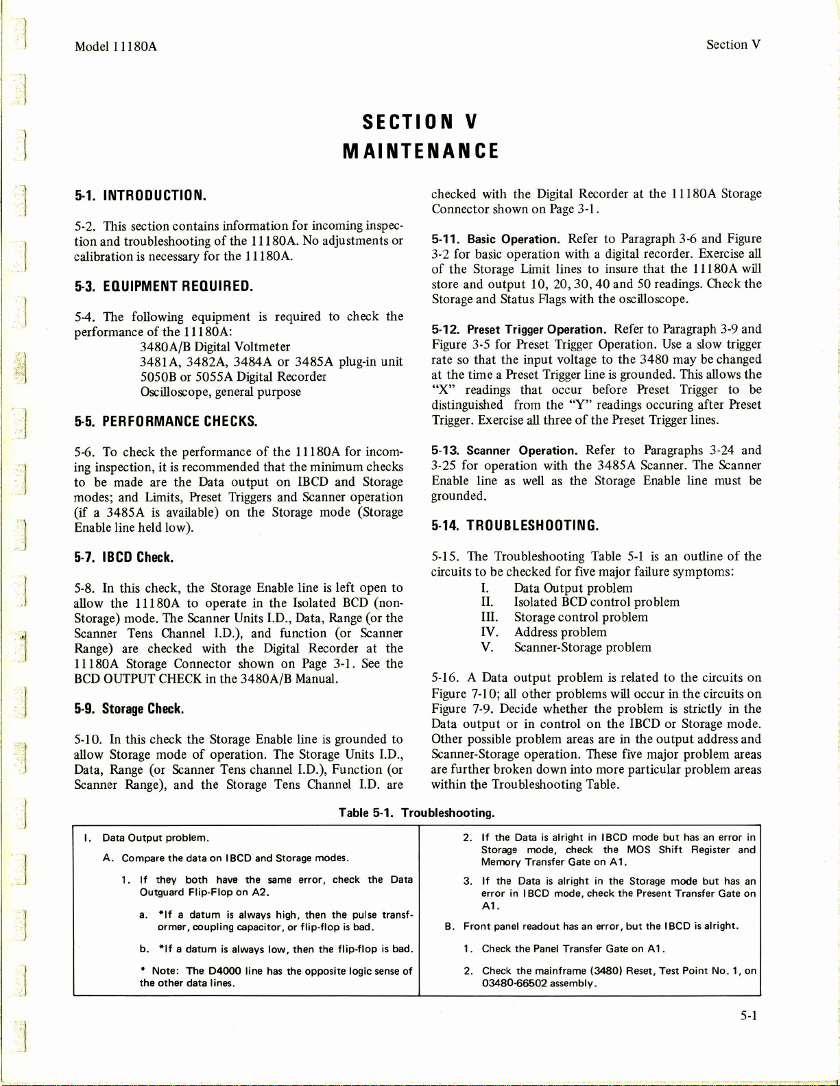
Model l l l 80A
Section
V
·1
.1
SECTION
MAINTENANCE
5-1.
INTRODUCTION.
5-2. This section contains information for incoming inspection and troubleshooting
is
calibration
5-3.
EQUIPMENT
necessary for the l l l 80A.
5-4. The following equipment
performance
of
the l l l 80A:
3480A/B Digital Voltmeter
3481 A, 3482A, 3484A or 3485A plug-in unit
5050B
Oscilloscope, general purpose
5-5.
PERFORMANCE
5-6.
To
check the performance
ing inspection, it
is
to be made are the Data output on
modes; and Limits, Preset Triggers and Scanner operation
is
(if a 3485A
available) on the Storage mode (Storage
Enable line held low).
of
the l l l 80A.
No
adjustments or
REQUIRED.
is
required to check the
or
5055A Digital Recorder
CHECKS.
of
the l l l 80A for incom-
recommended that the minimum checks
IBCD
and Storage
V
checked with the Digital Recorder at the
Page
Connector shown on
3-1.
5-11. Basic Operation. Refer to Paragraph 3-6 and Figure
3-2 for basic operation with a digital recorder. Exercise
of
the Storage Limit lines to insure that the l l l 80A
store and output 10, 20, 30 , 40 and
Storage and Status Flags with the oscilloscope.
5-12. Preset Trigger Operation. Refer to Paragraph
Figure 3-5 for Preset Trigger Operation.
so
rate
at the time a Preset Trigger line
"X"
distinguished from the
Trigger. Exercise
that the input voltage to the 3480 may
is
grounded. This allows the
readings that occur before Preset Trigger to be
"Y"
readings occuring after Preset
all
three
of
the Preset Trigger lines.
5-13. Scanner Operation. Refer to Paragraphs 3-24 and
th
3-25 for operation wi
as
Enable line
well
the 3485A Scanner. The Scanner
as
the Storage Enable line must
grounded.
5-14.
TROUBLESHOOTING.
l l l 80A Storage
50
readings. Check the
Use
a slow trigger
be
changed
3-9
all
will
and
be
J
5-7.
IBCD
Check.
5-8. In this check, the Storage Enable line
allow the
l l l 80A to operate in the Isolated
is
left open to
BCD
(nonStorage) mode. The Scanner Units l.D., Data, Range (or the
Scanner Tens Channel I.D.), and function (or Scanner
Range) are checked with the Digital Recorder at the
l l l 80A Storage Connector shown on
BCD
5-9.
OUTPUT
Storage
CHECK
Check.
in the 3480A/B Manual.
5-10. In this check the Storage Enable line
of
allow Storage mode
operation. The Storage Units I.D.,
Page
is
3-1.
See
the
grounded to
Data, Range (or Scanner Tens channel I.D.), Function (or
1.D.
Scanner Range), and the Storage Tens Channel
are
Table 5-1. Troubleshooting.
I.
Data
Output
problem .
A.
Compare the data
1 .
If
they
Outguard
a.
*If a datum
ormer
b.
*If a datum
Note:
*
the
other
on
IBCD
and Storage modes.
both
have the
Flip-Flop
, coupling capacitor,
is
The
D4000
data lines.
same
on
A2.
is
always high, then the pulse transf-
always
low,
line
has
error, check the Data
or
flip-flop
then the fli
the opposite logic
is
bad.
p-flop
sense
is
bad.
5-15. The Troubleshooting Table
circuits to be checked for
I.
Data Output problem
II.
Isolated
III.
Storage control problem
five
BCD
5-1
is
an outline
major failure symptoms:
control problem
IV. Address problem
V.
Scanner-Storage problem
is
5-16. A Data output problem
Figure
7-10;
all
other problems
Figure 7-9. Decide whether the problem
Data output or in control on the
related to the circuits on
will
occur in the circuits on
is
strictly in the
IBCD
or Storage mode.
Other possible problem areas are in the output address and
five
Scanner-Storage operation. These
major problem areas
are further broken down into more particular problem areas
within the Troubleshooting Table.
2.
If
of
the Data
Storage mode, check the MOS
Memory
If
the Data
3.
error
A1.
B.
Front
panel readout
1 . Check the Panel Transfer Gate on A 1 .
Check the mainframe (3480) Reset, Test
2.
03480-66502
is
alright
in I BCD mode
Transfer Gate on A 1.
is
alright
in I BCD mode, check the Present Transfer Gate on
assembly.
in the Storage mode
has
an
error,
but
the
but
Shift
IBCD
has
Point
Register and
is
an
error
but
alright
No.
of
has
the
in
an
.
1, on
5-1
Page 30
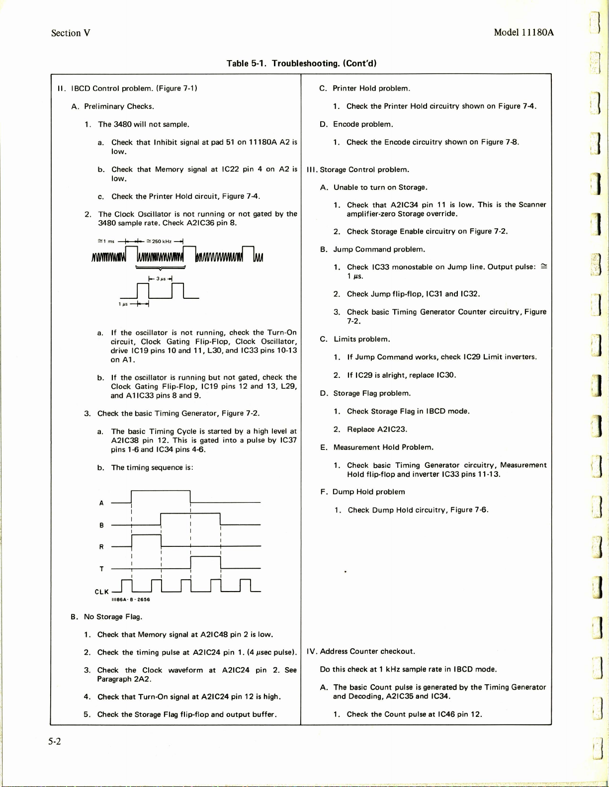
Section V
Model l l l 80A
11.
I BCD
Control
A.
Preliminary Checks.
1. The
2. The
3. Check
problem.
3480
a.
Check
low.
b.
Check
low.
c.
Check the Pri
Clock
3480
sample rate. Check A21C36
==
1
ms~
(Figure 7-1) C. Pri
will
not
sample. D. Encode
that
Inhibit
that
Memory
nter
Oscillator
:=
2sOkH
z
l-3µs-ol
_n____n_
1
µs
-+--I
a.
If
the oscillator
circuit,
drive
on Al.
If
b.
Clock Gating
and A 1
a.
The
A21C38 pin 12. This
pins 1-6 and IC34 pins 4-6.
b.
The
Clock Gating
IC19
pins
the oscillator
IC33
pins 8 and
the
basic
Timing
bas
ic
Timing
timing
sequence is:
10and
is
Flip-Flop,
Table 5-1. Troubleshooting.
signal at pad
signal at
Hold
circuit,
is
not
running
pin
51
IC22
Figure 7-4.
or
8.
-i
is
not
running, check the
Flip-Flop,
11,
L30
, and
running
but
not
IC19 pins 12 and 13,
9.
Generator, Figure 7-2.
Cycle
is
started
is
gated
by
into
on
11180A
pin 4 on
not
Clock
IC33
gated, check the
a high level at
a pulse
gated
by
Turn-On
Oscillator,
pins 10-
by
A2
A2
L29,
IC37
the
13
is
is
Ill.
(Cont'd)
nter
Hold
problem.
1. Check the Printer
problem.
1. Check the Encode
Storage
Control
problem.
A. Unable
B.
C.
D. Storage Flag
E.
to
turn
on
1. Check
2. Check
Jump
1. Check
2. Check
3. Check basic
Limits
1.
2.
1. Check Storage Flag
2. Replace
Measurement
1. Check basic
that
amplifier-zero Storage override.
Command
1 µs.
7·2 .
problem.
If
Jump
If
IC29
Hold
A21C34
Storage Enable
problem.
IC33
monostable
Jump
flip-flop,
Timing
Command
is
alright,
problem.
A21C23.
Hold
Timing
flip-flop
and inverter I
Hold
circuitry
circuitry
Storage.
pin
11
circuitry
on
IC31 and IC32.
Generator Counter
works,
replace IC30.
in
IBCD
Problem.
Generator
shown on Figure 7-4 .
shown on Figure 7-8.
is
low.
This
is
the Scanner
on
Figure 7-2.
Jump
line.
Output
circuitry,
check IC29
mode.
C33
Limit
circuitry
pins 11-13.
, Measurement
pulse:
Figure
inverters.
=:
i]
']
L .
:]
5-2
A
B
R
T
CLK
B.
No
Storage Flag.
1. Check
2. Check the
3. Check the
Paragraph
4.
Check
5. Check the
_J
11
186A · 8 -
that
that
I
I
I
26~6
Memory
timing
2A2.
Turn-On
Storage Flag
signal at A21C48 pin 2
pulse at A21C24 pin 1. (4 µsec pulse).
Clock waveform at A21C24
signal at A21C24
flip-flop
and
pin
output
12
is
low.
pin
is
buffer
2.
high .
Dump
Hold
Counter
check
problem
Dump
checkout
at 1 kHz
Count
A21C35 and
Count
Hold
circuitry,
.
sample rate
pulse
is
pulse
Figure 7·6.
in
generated
IC34
.
at
IC46
IBCD
by
pin
mode.
the
12.
Timing
Generator
F.
1. Check
IV.
Address
Do
See
.
this
A.
The basic
and Decoding,
1. Check the
...
'l.' •
Page 31

..
J
. J
.1
Model 11180A
a.
b.
2. Check
3. Check
IC32
4.
Check D
count
5. Check Tens Address
36.
a.
b.
c.
If
not
present, check
If
Reset
at
the
Count
the
pin
8.
output
rate.
output
low
both
Counter
.
is
IC21 pins 1-6.
Count
bad, check
Flop
If
. 5 µs
negative edge
Check
If
work
alright,
pulse
pulse
at
IC32
Counter
pulse.
of D output
flip-flops
counts
Table 5-1. Troubleshooting. (Cont'd)
the
Reset pulse
check
Computer
at
A 1 IC37
at
It
in
past
pin
8.
the
Units
pin
12.
It
should be 1/
at
output
input
at
of
IC43
50
and
or
A21C19
Units
IC44
1/0
should be in sync
at
Control
Address
pads
Address
.
flip-flop
IC36
pin 6 .
Flip·
Counter
10
34,
35
pin 2 for
with
Counter
does
the
and
the
not
Section V
Major
Scanner-Storage
1.
"Odd" * number
output
with
with
Scanner
2.
Skip
loss:
limit,
the
Storage
3.
Amplifier-Zero
fier
(the
given
scanned.
4.
a
Sync loss: Scanner reading (Channel
to
*An
"odd"
Storage
limit.
B.
"Odd"
1. Check
number
limit
zero reading.
last reading address
only
Storage address .
Scanner
number
that
problems
channel
the
Scanner
Control
with
the
Storage
of
.
loss: no
Note: the
when
an
limit
channel scan
the
Scanner
.
scan
limit
printings
printout
"odd"
with
Control
less
limit
Scanner
is
no
Enable signal
output
number
with
no
than the Storage
true
(low).
equal
to
does
not
of
the
Scanner
amp
of
number)
one
output.
not
line
00
of
equal
number
Enable
output:
the Scanner
zero reading
printed)
readings
is
equal
not
low.
limit
the
ampli-
equal
to
the
no
is
is
'.
:.
. 1
.. -.l
..
]
j
B.
If
A1,
A 1
IC29
IC18
C. Preset Trigger
1. Check
produce a low
2. Check
3. Check
4.
Check·
1-6.
5. Check
D.
Input
1. Check
2.
Replace
E. Status Flag
1. Check
2. Check
IC38
V.
Scanner-Storage
1) Check
2) Check
81,
and
.
Cycle
pins 3-6.
the
pin 13.
NOTE:
and enables Measurement
Cl
IC30, L25
input
the
for
the
the
Hold
at
input
IC44.
problem.
1/0
buffers
problem
Reset pulse
This
the
Preset and Reset gating
or
01
problem.
monostables IC41 and
pulse
Preset and Reset gating
a 1
µslow
Input
Cycle
Units
Counter
problem.
pads
flip-flop
IC18
.
at
Reset pulse ends
is
bad
at
the
through
of
Preset pulse
52
IC44
pins 8 and
L27,
approximately
Hold
override
preset
at
and
53.
.
9.
A21C45
Jump
Hold
command
Storage
and A21C15
IC42
1 µs .
IC40-42.
at
A21C20 pin
flip-flop
A 1 IC31
IC37
pins
pin
8 and I
Command
.
IC40-42.
output,
check
through
. Each should
8.
IC20
pin
6.
11-13,
C41
pins
and
2. Check the Scanner
a.
It
shou Id go
b.
It
should
3. Pin
12
of
problem
4. Check gate
13
Scanner
5.
An
C.
Skip
1. Check
the
2. Check
3. Check
taken.
D.
Amplifier-Zero
1. Check
13,
2. Check LI 1.
Sync loss:
E.
1. Check
major
2. Check
IC39
IC39
if it
should be high;
Home
"odd"
loss.
for
output
the
for
Amplifier
and gate
"Odd
problem
output
pin
7
pin
10
Home
low
at
produce
A1-IC34
is
A2-IC31 pins 8
scan
a high level
cycle .
Skip
reset
loss.
IC34
a high level at A
should be high.
not
high.
pin
Flag.
should
cause a
flip-flop A 1-IC34
of
the
Zero
pins 8
number
.
pulses
at A 1-IC39
Flag.
the
end
of a scan
through 13. Pins
10
should have a high pulse
jump
on
the Panel Transfer
Skip
flip-flop
flip-flop A 1-IC35
through
channel
.
1-IC34
See
"Skip
command.
pins 1
through
after
10.
scan
with
pins 7 and
pin 13.
loss'
9,
12 and
line
6.
one reading
pins 8
through
no
output"
10
.
major
at
during
is
]
A.
Check
then
decide
follows:
for
proper
on
the
operation
major
problem
with a 3481,
with
82
3485A
or
84
operation
plug-in,
as
Pin 7 pulse
output
cycle. Pin
Flag.
is
triggered
10
by
pulse
the
Panel Transfer
is
triggered
by
the
at
the
Scanner
end
of
an
Home
5-3
Page 32

I '
:l
."
J
:J
I ,
. . ' . ,
..
, . ' .
~
J
1J'
.
~
Page 33

Model l l 180A
,.
l
.-.:
SE
CTI
0 N VI
Section VI
~:
,;;:
:~;.~~
.-
. ]
...
· 1
'-"'
,.
']
.l
1
.]
J
.
]
J
J
REPLACEABLE
6-1.
INTRODUCTION.
6-2
. This section contains information for ordering replac
ment parts. Table
reference
de
part number
notes, and provides the following:
a. Total quantity used in the instrument (TQ column).
The total quantity
number appears.
b. Description
below.)
c. Typical manufacturer
(See Appendix A for list
d. Manufacturer's part number.
Miscell
6-3.
6-1
lists parts in alphameric order
of
signators and indicates the description,
of each part, together with any applicable
of
a part
is
given the first time the part
of
the part. (See list
of
the part in a five-digit code.
of
manufacturers.)
aneous parts are listed at the end
..
.......
...
. .
...
.
.. compositi
. .
e single-throw
..
enc
effect
. gallium arsenide
,.
.
.....
.
...
cyc
le(s)persecond)
.. ..
.....
.
.......
.
...
........
misc e
lectronic
silver
.aluminum
.ampere(s)
go
c
apa
cito
..
ceramic
coeffic
ient
..
common
connection
. .
deposited
.electrolyti
apsulated
. . . farad(s)
transistor
....
fixed
w+9 hertz
..
guard(ed)
.germanium
.ground(ed)
henry(ie
. . mercury
. asse
mbly
mot
..
batt
capacitor
diod e
delaylin
tamp
part
..
fuse
ery
A
g.
Al
A.
Au.
cer.
coef . . . .
com.
co
mp .
dop
DPDT
DPST.
elect.
encap. . .
F
FET field
fxd .
..
°""'
GHz
..
gd
Ge
....
H .
H
g.
Hz
A .
B . .
BT.
c
CR
DL .
DS.
E
F .
.
. .
double-pole double-throw
...
double-pol
: : : :
~-~henz
...
hertz(
........
of
abbreviations
of
Table 6-1.
ID
imp
g
incd
ld
ldl
.
r
kHz
L .
on
\in .
log.
mA
. . ...
MHz . . .
Mn . .
metflm
c
mfr
mtg
mV
. . .millivo
µF
. .
µs . .
µV
. .
my . .
oA
NC
.
No.
s)
NO.
NPO.
Prefix
~
..
mo"
kjJo
h
ecto
....
deci
FL
.
or
HR . . . . . he
IC
J . . . . .
K
e
L
M . me
MP mechanical part
p
...............
milliampere(s)= 10- 3
........................
.. ..
nanoampere(s)
..............
(zero
Symbols
Mo
Kor
.........
. . . . . . . .
kilohm(
. . kil
..
megahertz
megohm(
............
..........
.microvolt(s)=
.
.................
..
temperature
r Meg
k
h
..
............
..
.....
ohertz=
........
.... . . linear taper
lt(s)= 10- 3 volts
....... Mylar@
....
negative positive ze
..
..
6-4.
e-
their
-hp-
6to your local Hewlett-Packard Field Office. (See Appendix
B
Hewlett-Packard part numbers. Include instrument model
and serial numbers.
6-6.
6-
ABBREVIATIONS
insldediame1er
..
. .
impregnat
inc
andescent
.insulation(ed)
s) = J0"'"3 ohms
10+3 he
inductor
logarithmic
amper
= I
0+-6
s)"'
10+6
..
.. metalfilm
.
..
manufacturer
. millis eco
mounting
...
microfarad(s)
microsecond(s)
10 -6 volts
= I o
-9
amperes
normally
no rmally
coefficient
DECIMAL
Multiplier Prefix
1012
10'
10•
11>3
10'
10 fe
10-
l
..
int
egratedcirc
. . . relay s
.....
inductor
..
........
ed
rtz
tap
er
es
her
tz
ohms
nd
closed
neon
ope
n
ro
)
MULTIPLIERS
DESIGNATO
filter
ater
uit
jack
ter
plug
n .
obd
OD.
p
pA.
pF
"
piv
p/o .
poly
'"'
po•
,.,
ppm
prec
R .
Rh
"
·~
~
•I
Q .
QCR
R
RT .
T
TB.
TC.
TP
.
.......
·
RS
PARTS
ORDERING
5.
To obtain replacement parts, address order or inquiry
far list
NON-LISTED
7.
To
obtain a part that
a.
Instrument model number.
b. Instrument serial number.
c. Description
d. Function and location
nano
secon
.
. . .
not
separately
....
......
. . ...........
: :
..
. . ....
precision(temperature
coefficie
bility,and/ortolerance)
.............
.... .
S
ymbo
ls Multiplier
.,
cen
ti
milli
micr
o
pico
mto
INFORMATION.
of
office locations.) Identify parts by their
PARTS.
is
not listed, include:
of
the part.
of
the part.
..
d(s) = 10-9
seconds SPOT
replaceable
..
ohm(s)
order
by
description
. o
utside diameter
. .
.....
picoampere(s)
. .
printed
circuit
0
picofa
rad(
s)
10 - 12
farads
peak inverse voltage
part
position(s)
polystyr
.potiomete
.... peak-to·peak
.par
ts
per million
nt
, l
ongtermsta-
. . res
.rhodium
root-mean-squar
...
rotary
.
selenium
......
..
section(
........
silicon
. .........
10-2
10
- 3
10 -6
10
-9
10
- 12
10-15
10
- 18
..
transistor
. .
transistor
-diode V .
. .
.. resistor
thermistor
.switch x .
transformer
..
terminal
board
... thermocouple
..
test
point
peak
istor
slide
SPST
T•
TC.
TI02
tog
IOI
trim
TSTR.
V .
of
vu
ene
vdow
r
w.
w/
wiv .
w/o
e
s)
TS
W.
XDS
XF .
y
z ..
.
..
..
. .
.
..
..
..
. . single·pole double·throw
. .....
single-polesingle·throw
t
empe
rature
..
titani
....
..
alt
ernating
workin g voltage
dire
ct current
working
.. worki
ng inverse v
. . .
...
op
timum
value
factory,averagevalu
shown
(part
may b e
.no
standard
assigned(selected
@
Dupont
..
......
terminal
~~c~~~
tub
photocell,
.....
::. :::
. .... fuseholder
. . .
tantalum
coefficie
um
dioxid
...
toleranc
trimm
transistor
. .
volt(s)
current
.variable
voltage
..
watt(s)
. .
without
. . wire
wound
selected
omitte
type
number
special t
de Nemours
e, ne
on
..c
.
..
iamph
.c
. .
network
toggle
with
olt
strip
bulb,
etc
abl
socket
older
rystal
nt
e
e
er
age
at
e
d)
or
ype
.
e
6-1
Page 34

Secti
on VI
Table
6-1.
Replaceab
Model
1118
0A
le
Par
ts
:l
Reference
Designation
Al
Al
Cl
AlC
2
AlC3
AlC4
AlC
5
AlC6
AlC7
AlC
8
AlC9
AlC
10
AlCll
AlC12
AlCl3
AlC14
AlCl5
AlCl6
AlC17
AlCl8
AlC19
AlC20
AlC21
AlC22
AlC23
AlC24
AlC25
AlC
26
Al C27
AlC
28
AlC29
AlC
30
AlC31
AlC3
2
AlC3
3
AlC34
AlC3
5
AlC36
AlC37
AlC38
AlC
39
A 1C4 0 01 6 0-0 99 0 1
AlC41
AlC4
2
AlCRl
All
Cl
AllC2
AllC3
AllClt
AllC5
AllC6
AllC7
AllC8
AllC9
All C 10
AllCll
Al1Cl2
Al1Cl3
AllCllt
Al1Cl5
AllC 16
All
Cl
7
All C 18
Al1Cl9
'
All C20
AllCZl
AllC22
AllC23
AllC24
All
C25
AllC26
All
CZ
7
A
l!
C 28
All
C29
All
C30
AU
CH
All
C32
HP Part Number
11180-66501
0160-0300
0160-0300
'
)160-0300
0160-03
00
~160-0300
0160-030
0
0160-0300
0
016
0160-0300
0
0160-0300
0160-0300
0160
0160-0300
0160-0300
0160
0160-0300
0160-03
0
0160-030
0160-0300
0160-0300
01
0160-0300
0
0160-030
0160-0300
0
0160-0300
0
0160-0300
018
0180-0197
0150-006
0
0
0
0
0160-015
1901-0
1820-0728
1820-07
1820-072
1820-0728
1820-0728
1820-072
1820-072
1820-0728
1820-072
1820-0728
1820-072
1820-0728
1820-03"9
1820-0349
1820-0349
1820-0349
1820-0349
1820-0349
1820-0349
1820-0349
1820-0349
1820-0349
18
1820-0349
1820-0349
1820-0349
18
1820-0349
1820-0349
1820-0349
1820-0586
18
0
160-0300
160-030
0
0-0300
160-0300
- 03
00
- 0 3
00
00
160-0300
0
60-03
00
160-0300
0
160-0300
160-0300
0-1701
4
160-0161
160-01
57 1
160-015
3
160-
2 9 6 4 2
3
040
28
8
8
8
8
8
20-0349
20-0349
20-0322
Oty
38
1
11
12
20
BOARD
l
C:FXD
C:FXD
C:FXD
C:
FXO
C
:FX
C:F
C
:FXD
C
:FXD
:FXD
C
C:FXD MY 0.00
C:FXD
C: FXD
C:F
C
:FXD
C:FXD
C:F
C:FXD
C:F
C:FXD
C:FXO
C:FXD
C:F
C:F
C:F
C:FXD
C:FXD MY
C:
FXD
C: FXD
C:
FXO
C:
F XD
C:FXD
C:FXD
C:FXD
C:FXO
3
C:FXD
l
C:F
C: FXD
1
C:F
FXD
C:
C: FXD
C:FXD CER DIS
C :FXD MY 0.
DIOOE:SILICON 30MA
4
IC:DIGITAL
IC:OIGITAL
IC
:DIGITA
IC:DIGITAL
IC:DIGITAL
IC:DIGITAL
IC
:DIGITAL
IC:OIGITAL
IC :DIGITAL
IC:DIGITAL
IC
:DIGITAL
IC:DIGITAL
IC:DTL
1c
:on
IC:OTL
IC
: DTL
IC:OTL
IC
: DTL QU
IC
:OTL
1c:on
IC:DTL
IC
: DTL
IC:DTL
IC:OTL
IC:DTL
1c
:on
l C
:DTL
1c
:on
1c
:on
I C
:OTL
IC:
6
IC:TTL
1
Description
AS
SY:MAIN
MY 0.0
027
MY 0.0027
MY 0.0
MY 0.0
D
MY
XD
MY 0.0027
MY
MY 0.00
MY
MY
MY
XD
MY 0.0021
MY
MY 0.0027 UF
XD
MY 0.0021 UF 200VDCW
MY
XD
MY 0.00
MY
MY
HY 0.002 7
XD MY
XD
HY
XO MY 0.0027
MY 0.0
MY
MY 0.00
MY
MY
MY
MY
MY 0.0
ELECT
ELECT 2
CER 0.1 UF
XD
MY
XO HY Q.00
HY 0.001
MIC
A 1 0 0
QUAD 2-INPT
QUAD
QUAD
QUAD 2-INPT
QUAD
QUAD
QUAD
QUAD
QUAD
QUAD
QUAD
QUAD 2-INPT
QUAD 2-INPT NANO
QUAD
QUAD
QUAD
QUAD 2-INPT
OI G
ITAL
DECADE
UF
UF
UF
027
027
UF
0.0
021
UF
UF
0.0021
27
UF 2 00VDCW
UF
0.00
21
UF
21
0.0027
UF
0.0027 UF
UF
UF 200
0 . 0 027
UF 2 00VOCW
0.0021
21
UF 200
0.00
27
UF 200VOCW
0.00
27 UF 200VDCW
UF
UF
0.00
21
0.00
27
UF
UF 200VDCW
021
UF 2 00VDCW
.00
21
UF
0
0 . 0
021
UF
21
UF 200VDCW
0.00
21
UF
0.00
27
UF
UF 200VDCW
0.0021
0.00
21 UF 200VDCW
027
UF
UF 2
6.8
.2
UF 101: 20VD
+60%
UF l
0.01
47
UF l Oi 200VDCW
UF
PF
2% 3 0 0 VDCW
C 0.
01
UF
001
UF 10% 2
TTL
+ LO
TTL
+ LOGIC
L
+ L O
TTL
TTL
+ L OGIC
TTL
+ LOG
TTL + LOG
TTL +
TTL
+ LOGIC
TTL +
TTL + LOGIC
TTL + LOGIC
TTL
+ LOGIC
2-INPT
2
-INPT
2-INPT
2-
INPT NANO
AD
2-INPT
2-INPT
2
-INPT
2-INPT
2-lNPT NANO
2- l NPT
2-
INPT
2-
INP
2-IN
TTL
HEX CONVER
DIVIDER
UF
10
+60-2
LOGIC
LOGIC
T
PT
200VDCW
20 0
VDCW
200VDCW
200
VDCW
200
VDCW
200
VDCW
2
OOVDCW
200VDCW
200
VOCW
200VDC
W
200VDCW
200
VDCW
VDCW
200VDCW
VDCW
200
VDCW
200VDCW
200
VDCW
200VDCW
20DVDCW
200
VDCW
200VDCW
200VDCW
oi
6VDCW
CW
-20% l OOVD CW
Og
20 0
VOCW
1:
200
VDCW
0%
25VDCW
00
VDC
W
30HV
GIC
GIC
IC
IC
NANO
GATE
NANO
GATE
NANO GATE
l;ATE
NANO
NANO
GATE
GATE
NANO GATE
GATE
NANO
NANO
GATE
NANO
GATE
GATE
NANO
GATE
NANO GATE
GATE
NANO
GATE
NA
NO GAT E
NANO GATE
GATE
NANO
TER
Mfr
Code
2
8480
56289
56289
562
89
5628
56289
5
628
56
28
28
56
289
56
56289
56
289
56289
56
2 89
56289
56289
56
289
562
89
56 289
56289
89
56 2
56289
56289
56289
28
56
56
289
5628
562
89
56
28
56289
56289
89
562
56289
56
289
28480
5628
7
2962
5628
56289
56
289
00
653
7 29
62
562 69
07
263
28480
284
80
28480
284
80
284
80
281t80
2
84
80
284
80
28480
2848
284
80
2
848
0129
01295
0 129 5
0129
01295
01295
01295
01295
01295
01295
01295
01295
01295
01295
012
9 5
01 2 95
0 12
95
0
1295
28
480
56"289
9
9
9
9
9
9
9
9
9
0
0
5
5
Mfr
Part Number
11180-66501
l 92P27292-PT
l
92
P272
92-PT
l9
2P27 292
l
92
l
92P272
l92P27292
l
92P27292-PT
192P27292-PT
192P27292-PTS
l 9 2P
92P27292-PT
l
l92P27292-PT
l 9
l92P27292-PTS
l92P272
92P27292-PT
l
l
92P27292-PT
192P27292-PTS
l 92P2 7292
l
92P27292-PTS
l92P27292-PT
l92P27292-PTS
l
92P
192P27
192P27292-PT
192
92
1
192P27292-PTS
192P27292-PT
l
92
192P27292-PT
192P27292-PT
l92P27292-PT
0180-1701
150D225X902
61
l92Pl0
l 9 2
92
1
RDM1
563
192P102
FDG1
1820-07
18
18
1820-072
1820-07
1820-07
1820-07
1820-072
1
82
1820-0728
1820-072
1820-072
SN150 31
S
N15031
SN15031
S
N15031
SN15031
SN15031
SN15031
SN15031
SN15031
SN15031
SN15031
SN150
SN1503l
5'1150 31
SN
S
N15031
SN
S
N15031
18
N8280A
-PT
P27
292-
92-PT
- PTS
27292-PTS
2P27292-PT
92-
-PT
2729-2
-PTS
292
-PTS
P27292-PT
P27
292
-PT
P 2 7
292
-PT
31-100-651-1042
392
- PTS
P4 7292-P
Pl0
292
-PT
5F101G3
S
5-000-Y5UD-10
92 -PTS
088
28
20-0
728
20-07
28
8
28
28
28
8
0-0
728
8
8
31
1503l
15031
20-05
86
PTS
PTS
0A2
TS
S
S
S
S
S
S
S
S
S
S
S
S
S
S
S
S
S
S
S
S
S
-DY
S
S
3Z
~
.J
·]
.·
' .
']
]
6-2
See introductio n
to
this section for
ord
er ing informatio n
Page 35

· 1
Model 11180A
Table
6-1. Replaceable Parts
(Cont'
Section
VI
d)
--]
·l
--
--·_
\
:~~
. ·_ 1
--
J
]
J
Reference
Designation
AllC33
AllC34
Al!C35
AllC36
Al!C37
A
11
C38
Al1C39
Alli
Al
l2
All3
All4
Al
l 5
All6
All7
All
8
All9
AlllO
Alli
l
All
12
Alll3
Alll4
Alll5
Alll6
Alli
7
Alll8
Alll9
All20
All21
All22
All23
All24
All2
5
All26
All27
All28
All29
All30
All31
All3
2
All33
All34
All35
All36
All37
All38
Allll
All12
All13
AlQl
AlQ2
AlQ3
Al~4
AlQ5
AlQ6
AlQ7
AlQ8
AlQ9
AIU
AlR2
AU3
AlR4
AH5
AlR6
AH7
AlR8
Al
~9
AlRlO
AlRll
AlRl2
AlRl3
AlRl't
AlR15
AlR16
AlR17
AlR18
HP Part Number
1820-0307
1820-0349
1820-0349
1820-0586
1820-0583
1820-0583
1820-0730
9100-3222
9100-322
9100-3222
9100-3222
9100-3222
9100-3222
9100-3222
9100-3222
9100-322
9100-3222
9100-3222
91('0-3222
9100-3222
9100-3222
9100-3222
9100-3222
9100-3222
9100-3222
9100-3222
9100-3222
9100-3222
9100-3222
9100-3222
9100-3222
9100-3222
9100-3
9100-3222
9100-3222
9100-3222
9100-3222
9100-3222
9100-32
9100-3222
9100-3223
9100-3223
9100-3223
9100-3223
9100-3223
1990-0312
1990-0312
1990-0312
1854-0042
1854-00't2
l85't-007l
1854-0071
185"-0071
18
1854-0071
1854-0071
1853-0010
068't-l
0757-04't2
0757-0't42
068't-l021
0684-2231
0684-1021
0684-1021
068't-l021
0
0684-1021
0684-2231
06B4-1031
0
~6
0684-3911
068
0684-2221
0684-2221
5't-007l
684-1811
68't-1021
84-10
4-3311
2
2
222
22
021
21
Oty
IC:OIGITAL
l
IC:DTL
IC:OTL
!C:OIG!TAL
11
38
39
1 6
IC:TTL
IC:TTL
l
IC:O!GITAL
CO
COIL:FXO
CO
COIL:F
COIL:FXO
COIL:FXD
COIL:FXD
COIL:FXD
COIL:FXD
CO!L:FXD
CO!L:FXO
CO!L:FXD
COIL:FXD
COIL :FXO
COIL:FXD
COILIFXO
CO
COIL•FXD
COIL:FXD
CO!LIFXD 100
COILIFXD
CO!LIFXD
COIL:FXD
CO!L:FXD
COIL:FXO
CO!L:FXD
CO
COIL:FXO
CO
COIL:FXD
COIL:FXD
COIL:FXD
COIL:FXO
COIL:FXO
COIL:FXD
COIL:FXD
COIL
COIL :FXD
3 TSTR:PHOTO
TSTR:PHOTO
TSTR:PHOTO
TSTR:SI
2
TSTR:SI
9
TSTR
TSTR:SI
TS TR:
TSTR:SI
TSTR:
TSTR:S
l
TSTR:SI
R:FXO
2 R:FXD
R:FXD
R:FXD
R:FXO
5
R:FXD
R:
R:FXD
2 R•FXD
R:
R:FXO
R:
R:FXO
R:FXO
l R :FXO
3 R :FXD
R:FXD
R:FXD
"
QUAD
QUAD
QUAO
QUAD
IL:
FXO
100
100
IL:
FXO
100
XO
100
100
100
100
100
100
100
100
100
100
100
100
100
IL:
FXD
100
100
100
100
100
100
100
1
00
100
IL:
FXD
100
100
IL:
FXD
100
100
100
100
100
2
20
22
220
:FXO
220
220
NPN
NPN
:SI
NPN
NPNISELECTED
SI
NPNISELECTED
NPNI
Sl
NPNISELECTED
l NPNISELECTED
PNPISELECTED
COMP
MET
MET
FLM
COMP
COMP
COMP
FXD
C~MP
COMP
COMP 180
FXD
C 0 MP
COMP
FXO
C014P
COMP 1000 OHM
COMP
COMP
COMP
CO~P
COMP
Description
OTL
HEX
INVERTER
2-INPT
NANO
2-!NPT
HEX
2-INPT
2-!NPT
+ LOGIC
UH
UH
UH
UH
UH
UH
UH
UH
UH
UH
UH
UH
UH
UH
UH
UH
UH
UH
UH
UH
UH
UH
UH
UH
UH
UH
UH
UH
UH
UH
UH
UH
UH
UH
UH
UH
UH
UH
ED FROM
SELECTED
OHM
10.0K
10.0K
OHM
OHM
OHM
OHM
OHM
OHM
OHM
KOHM
OHM
OHM lOi
OHM
OHM
NANO GATE
CONVERTER
NANO
NANO
lOi
lOi
lOi
lOi
10i
TTL
TTL
0
I SELECT
1000
FLM
1000
22K
1000
1000
1000
100 0 OHM
22K
1 0
1000
390
330
2200
2200 OHM
GATE
GATE
GATE
2N3704)
FROM
2N3704l
FROM
2N3704)
FROM
2N3701tl
FROM
2N3704)
FROM
2N370't)
FROM
2N325ll
lOi
1/4W
OHM
ti
OHM
ti
lOi
l/4W
l/4W
lOi
l/4W
lOi
l/4W
lOi
l/4W
l/4W
1 0% 1/4 W
l/4W
l/4W
lOi
l/4W
lOi
l/4W
l/4W
l /4W
lOi
l/4W
lOi
l /4W
l/8W
l/8W
Mfr
Code
28480
0
129
01295
28480
28480
28480
28480
28480
28480
28480
28480
28480
28480
28480
2848
28480
284
80
28480
28480
28480
28480
28480
28480
28480
2
8480
28480
28480
28480
28480
28480
28480
2848
28480
28480
2848
28480
28480
28480
28480
28
480
2848
28480
28480
28480
28480
28480
28480
28480
28480
284
80
28480
28480
284
80
28480
28480
284
80
28480
01121
28480
28
480
01121
01121
01121
01121
01121
01121
0 11 21
0 11
21
01121
01121
01121
01121
01121
01121
01121
5
0
0
0
0
Mfr
Part Number
1820-0307
SN15031
SN15031
1820-0586
1820-058
1820-05
1820-0730
9100-3222
91~0-3222
9
9100-3222
9100-3222
9100-3222
9100-3222
9100-3222
9100-3222
9100-3222
9100-3
9100-3222
9100-32
9100-3222
9100-3222
9100-3222
9100-3222
9100-322
9100-3222
9100-3
9100-3222
91009100-3222
9100-3222
9100-3222
9100-322
9100-3222
9100-3
9100-32
9100-3222
910091
9100-3222
9100-322
9100-3223
9100-3223
91
9100-3
1990-0312
1990
1990-0312
1854-004
1854-0
1854-0
1854-0071
1854-0071
1854-0071
1854-0
1854-0071
1853-0010
CB
0757-0442
0757-0442
CB
CB
CB
CB
CB
CB
CB
CB
CB 1031
CB
CB
CB
CB
CB
ca
100-32
00-3222
00-3223
-03
1021
1021
2231
1021
1021
1021
1811
102
2231
1021
1021
3911
3311
2221
2221
222
222
3222
222
3222
223
042
0 71
071
1
3
83
22
22
l
2
22
3
12
2
See
introduction
to
this
section
for
ordering
information
6-3
Page 36

Section
VI
Reference
Designation
AlR19
AlR20
AH21
AlR22
AH23
All
All
All
All
All
All
AZ
A2Cl
A2C2
A2C3
A2C~
A2C5
A2Cb
A2C7
A2C8
A2C9
A2Cl0
A2Cll
A2Cl2
A2Cl3
A2Cl4
A2Cl5
A2Cl6
A2Cl
1
A2Cl8
A2Cl9
A2C20
A2C21
A2C22
A2CR1
A2CR2
A2CR3
A2C~4
A2CR5
A2C~6
A2CR7
AZ I Cl
A2IC 2
A21C3
A2!C4
A21C5
A21Cb
A21C7
A21C8
A21C9
A21C10
A21C11
A21C12
A21Cl3
A2IC
14
A21Cl5
A2IC
lb
A21Cl7
A2IC
18
A21Cl9
A21C20
A2IC21
A21C22
A21C23
A2IC24
A21C25
2b
A21C
A21C27
A2IC28
A21C29
A21C30
A21C31
A2!C32
A21C33
A21C
34
HP Part Number
0684-1531
0684-2221
0684-1811
0684-2231
0684-2231
0363-0058
1200-0437
1200-0449
1200-0450
4040-0748
4040-0753
11180-66502
0180-0309
0180-1701
0160-0153
0180-1701
0160-0153
0160-0153
0160-0153
0160-0153
0160-0153
0150-0055
0150-0055
0160-0300
0160-0300
0160-0300
0160-0300
0160-0300
0160-2964
0160-0153
0160-0298
0160-0153
0160-0153
1901-0045
1901-0045
1901-0040
1902-3073
1902-3073
1901-0040
1901-0040
1820-0584
1820-0584
18
20-0
584
1820-0584
1820-0
584
1820-0584
1820-0174
1820-0584
1820-0584
1820-0174
1820-0584
1820-0584
1820-0
584
1820-0584
1820-0174
1820-0584
1820-0584
1820-0174
1820-0586
1820-0583
18
20-0
0 5 4
1820-0583
1820-0590
1820-0588
1820-01
74
1820-0054
1820-0583
1820-0587
1820-0586
1820-0591
1820-0588
1820-0583
1820-0583
1820-0584
Oty
12
72
15
Table 6-
R:FXD
R:FXD
R:FXD
R:FXD
R:FXD
CONTACT:ELECT.
2
SOCKET:IC
SOCKET:IC
SOCKET:IC
2
EXTRACTOR:PC
1
EXTRACTOR:PC
BOARD
C:FXO ELECT
NOT
ASSIGNED
C:FXD ELECT
C:FXD
C:FXD
C:FXO
C:FXO
C:FXD
C:FXD
C:FXD
C:FXO
C:FXD
C:FXD
C:FXO
C:FXD
C:FXO
C:FXD
C:FXD
C:FXD
C:FXD
C:FXD
C:FXD
DIOOE:SILICON
OIOOE:SJLICON
OIOOE:SJLICON
DIODE BREAKOOWN:4.32V
DIODE BREAKDOWN:4.32V
OIOOE:SJLICON
DIOOE:SILICON
IC:TTL
IC:TTL
JC:TTL
IC:TTL
JC:TTL
IC:TTL
INTEGRATED
JC:TTL
JC:TTL
INTEGRATED
JC:TTL
IC:TTL
JC:TTL
IC:TTL
INTEGRATED
JC:TTL
IC:TTL
INTEGRATED
IC:OJGITAL
IC:TTL
JC:TTL
IC:TTL
IC:OIGITAL
JC:TTL
INTEGRATED
IC:TTL
IC:TTL
IC:TTL
4
JC:OJGITAL
IC:TTL
IC:TTL
IC:TTL
IC:TTL
IC:TTL
1. Replacement
Description
COMP
15K
OHM
COMP
2200
COMP
180
COMP
22K
COMP
22K
8 PIN
14
16
ASSY:PIG
MY
0.001
ELECT
HY
0.001
MY
0.001
MY
0.001
MY
0.001
MY
0.001
Tl
DIOXIDE
Tl
DIOXIDE
MY
0.0027
MY
0.0027
MY
0.0027
MY
0.0027
MY
0.0027
CER
DISC
MY
0.001
MY
0.0015
MY
0.001
MY
0.001
QUAD
QUAD
QUAD
QUAD
QUAD
QUAD
CIRCUIT:TTL
QUAD
QUAD
CIRCUIT:TTL
QUAD
QUAD
QUAD
QUAD
CIRCUJT:TTL
QUAD
QUAD
CIRCUIT:TTL
TTL
QUAD
QUAD
QUAD
TTL
DUAL
CIRCUJT:TTL
QUAD
QUAD
TRIPLE
TTL
INPT ANO-OR-INVERT
DUAL
QUAD
QUAD
QUAD
OHM
OHM
OHM
OHM
0.700"
CONTACT
CONTACT
BOARD,
BOARD,
4.7
UF
6.8
UF
UF
6.8
UF
UF
UF
UF
UF
UF
UF
UF
UF
UF
UF
0.01
UF
UF
UF
UF
0.75A
0.75A
30MA
30MA
30MA
2-INPT
2-INPT
2-INPT
2-INPT
2-INPT
2-INPT
2-INPT
2-INPT
2-INPT
2-INPT
2-INPT
2-INPT
2-INPT
2-INPT
HEX
2-INPT
2-INPT
2-INPT
DUAL
4-INPT
2-INPUT
2-INPT
3-INPT
HEX
4-INPT
2-INPT
2-INPT
2-INPT
lOl
lOi
lOl
lOl
20l
20l
lOl
20l
IOl
lOl
lOl
!Ol
lOl
10
10
200VDCW
200VDCW
200VDCW
200VDCW
200VDCW
lOl
lOl
lOl
lOl
30WV
30WV
30WV
NOR
NOR
NOR
NOR
NOR
NOR
NOR
NOR
NOR
NOR
NOR
NOR
NOR
NOR
CONVERTER
NANO GATE
NANO
NANO
NANO
NANO
CONVERTER
NANO
NANO
NANO
NOR
Parts
(Co
nt'd)
l/4W
lOl
l/4W
l/4W
l/4W
l/4W
LG
BLACK
GREEN
lOVDCW
6VDCW
200VDCW
6VOCW
200VDCW
200VDCW
200VDCW
200VDCW
200VDCW
PF
5l
500VDCW
PF
5l
500VDCW
UF
+80-20l
200VDCW
200VDCW
200VDCW
200VDCW
lOOPIV
lOOPIV
5l
5l
GATE
GATE
GATE
GATE
GATE
GATE
HEX
INVERTER
GATE
GATE
HEX
INVERTER
GATE
GATE
GATE
GATE
HEX
INVERTER
GATE
G~TE
HEX
INVERTER
GATE
GATE
2-WIOE,JNPT
GATE
HEX
INVERTER
NANO
GATE
GATE
NANO
GATE
GATE
GATE
GATE
GATE
GATE
25VDCW
AND/OR
Mfr
Code
01121
01121
01121
01121
01121
91662
17117
17117
17117
28480
28480
28480
56289
28480
562
89
28480
562
89
56289
562
89
56289
562
89
78488
78488
56289
562
89
562
89
56289
56289
7298
56289
56289
56289
562
89
04713
04713
07263
04713
04713
07263
07263
28480
28480
28480
28480
28480
28480
01295
28480
28480
01295
28480
28480
28480
28480
01295
28480
28480
01295
28480
28480
0
129
28480
28480
28480
01295
01295
28480
28480
28480
28480
28480
28480
28480
28480
Mfr
CB
CB
CB
CB
CB
02-005-12
5566-235-5
7014-295-5
7016-295-5
4040-0748
4040-0753
11180-66502
1500475X0010A2-0YS
0180-1701
l
92Pl
0180-1701
l
92Pl0292-PTS
l
92Pl0292-PTS
192Pl0292-PTS
192Pl0292-PTS
l
92Pl
TYPE
TYPE
192P27292-PTS
192P27292-PTS
192P27292-PTS
192P27292-PTS
l92P27292-PTS
5835-000-Y5UO-l03Z
2
l92Pl0292-PTS
l
92P
192Pl0
192Pl0292-PT
SR1358-7
SR1358-7
FOG1088
sz
sz
FOG1088
FOG1088
1820-0584
1820-0584
1820-0584
1820-0584
1820-0584
1820-0584
SN8199
1820-0584
1820-0584
SN8199
1820-0584
1820-0584
1820-0584
1820-0584
SN8199
1820-0584
1820-0584
SN8199
1820-0586
1820-0583
SN
5
1820-0583
1820-0590
1820-0588
SN8199
SN4342
1820-0583
1820-0587
1820-0586
1820-0591
1820-0588
1820-0583
1820-0583
1820-0584
Mo
Part Number
1531
22 21
1811
2231
2231
0-612
5
0292-PTS
0292-PTS
GA
GA
15292-PTS
292
-PTS
S
10939-77
10939-77
4342
del
11180A
l
..
]
J
]
·]
]
J
I
6-4
See
introduction
to
this
section
for
ordering
J
information
Page 37

Model 11180A
Table
6-1.
Replaceable Parts
(Cont'd)
Section
VI
•,
··
·1
.·.
J
. J
· 1
_]
Reference
Designation
A2lc35
AZIC36
AZIC37
AZ!
C38
AZ!C39
A2JC40
A21C41
AZIC42
AZIC43
AZIC44
A2IC45
A2JC46
AZIC47
A21C48
A2ll
A2L2
AZL3
AZL4
AZL5
AZL6
A2L
7
A2L8
AZL9
AZLlO
AZLll
AZLlZ
AZL13
AZL14
A2ll5
A2ll6
AZLl 7
A2Ll8
A2Ll9
AZL20
AZLZl
AZL22
A2L23
AZL24
AZL25
AZL26
AZL27
A2L28
A2L29
A2L30
A2L31
AZL32
A2L33
A2L34
A2L35
A2L36
A2L37
A2L38
AZL39
A2Ql
A2Q2
A2Q3
A2Rl
A2RZ
AZR3
A2R4
AZR5
A2~b
A2R7
A2R8
A2R9
A2Rl0
A2Rll
A2U2
AZR13
A2Hlt
A2Rl5
AZR16
AZRl 7
A2Rl8
AZR19
HP Part Number
1820-0595
1820-0537
1820-0583
1820-0587
1820-0207
1820-0587
1820-0583
1820-0586
1820-0076
1820-0595
1820-0588
1820-0587
1820-0586
1820-0583
9100-3223
9100-3223
9100-3223
9100-3223
9100-3223
9100-3223
9100-3223
9100-3223
9100-3223
9100-3223
9100-3223
9100-3223
9100-3223
9100-3223
9100-3223
9100-3223
9100-3223
9100-3223
9100-3223
9100-3223
9100-3223
9100-3223
9100-3223
9100-3223
9100-3223
9100-3223
9100-3223
9100-3223
9100-3223
9100-3223
9100-3223
9100-3223
9100-3223
9100-3222
9100-3222
9100-3222
9100-3222
9100-3222
9100-3223
1854-0071
1854-0071
1854-0071
0684-4
711
0684-6821
0684-6821
0684-6821
0684-6821
C684-6821
0684-6821
0684-6821
0684-6B21
06B4-1021
0684-1021
0684-1021
0684-1021
0684-1021
0684-1021
0684-1021
068't-2221
0684-1
Bltl 2
0684-1841
Oty
2
1
1
1
1
16
!C:TTL
DUAL
JC:TTL
DUAL
JC:TTL
QUAD
TRIPLE
JC:TTL
!C:TTL
MONOSTABLE
JC:TTL
TRIPLE
JC:TTL
QUAD
JC:DJGJTAL
IC:TTL
DUAL
JC:TTL
DUAL
DUAL
JC:TTL
JC:TTL
TRIPLE
JC:DIGITAL
IC:TTL
QUAD
COIL:FXO
COIL:FXO
COJL:FXD
COIL:FXD
COIL:
FXD
CO
ll:FXD
COIL :FXD
COIL:FXD
COIL :FXD
COIL:FXD
COJL:FXD
COIL:FXD
COIL:FXD
COIL:FXD
COIL:FXD
COIL:FXD
COIL:FXD
COJL:FXD
COIL:FXD
COIL:FXD
COIL:FXD
COIL:FXD
COIL:FXD
COIL:FXD
COIL:FXD
COIL:FXD
COIL:FXD
COJL:FXD
COIL:FXD
COIL:FXD
COIL :FXD
COIL:FXD
CO!l:FXD
COIL:FXD
COIL:FXD
COIL:FXD
COIL:
FXD
COIL:FXD
COIL:FXD
TSTR:SJ
TSTR:SI
TSTR:SJ
R:FXO
COMP
R:FXD
COMP
R:FXD
COMP
R :FXD
COHP
R:FXD
COHP
R:FXD
COHP
R:FXD
COHP
COHP
R•FXO
R:FXD
COHP
R:FXO
COHP
R:FXD
COHP
R:FXD
COMP
R:FXD
COHP
R:FXD
COHP
R:FXD
COMP
COHP
R•FXD
R:FXD
COMP
R:FXD
COHP
R:FXD
COHP
Description
J-K
MASTER
4-INPT
2-INPT
3-JNPT
MULTIVIBRATOR
3-INPT
2-INPT
TTL
HEX
MASTER/SLAVE FF
J-K
MASTER
4-INPT
3-INPT
TTL
HEX
2-INPT
220
UH
220
UH
UH
220
220
UH
UH
220
zzo
UH
UH
220
UH
220
UH
220
220
UH
UH
220
UH
220
UH
220
UH
220
UH
220
UH
220
UH
220
220
UH
220
UH
zzo
UH
220
UH
UH
220
220
UH
220
UH
220
UH
220
UH
zzo
UH
220
UH
UH
220
UH
220
UH
220
220
UH
UH
220
UH
100
100
UH
100
UH
UH
100
100
UH
220
UH
NPNC
SELECTED
NPNCSELECTED
NPNCSELECTED
470
OHM
6.8K
OHM
6.8K
OHM
6 .SK
OHH
6.8K
OHH
6.8K
OHH
6.BK
OHH
6.8K
OHH
6.8K
OHH
OHM
1000
OHH
1000
1000
OHH
OHH
1000
OHH
1000
OHH
1000
OHM
1000
2200
OHM
180K
OHM
180K
OHM
SLAVE
NANO
GATE
NANO
GATE
NANO
GATE
NANO
GATE
NANO
GATE
CONVERTER
SLAVE
NANO
GATE
NANO
GATE
CONVERTER
NANO
GATE
FROM
2N3704J
FROM
2N3704l
FROM
2N3704J
lOi
l/4W
10i.l/4W
lOi
l/4W
lO:S l /4W
l/4W
lOi
l/4W
loi
l/4W
loi
l/4W
loi
l/4W
loi
lO:l
l/4W
l/411
10i
11411
loi
1/411
10i
l/4W
10i
l/4W
loi
l/4W
loi
1/411
loi
1/411
loi
l/4W
10i
F/F
F/F
Mfr
Code
28480
28480
28480
28480
28480
28480
28480
28480
01295
28480
28480
28480
28480
28480
28480
28480
28480
28480
28't80
28480
28480
28480
28480
28480
28480
28480
28480
28480
28480
28480
28480
28480
28480
28480
28480
28480
28480
28480
28480
28480
28480
28480
28480
28480
28480
28480
28480
28480
28480
28480
28480
28480
28480
28480
28480
28480
01121
01121
01121
01121
01121
01121
01121
01121
01121
01121
01121
01121
01121
01121
01121
01121
01121
01121
01121
Mfr
Part Number
1820-0595
1820-0537
1820-0583
1820-0587
1820-0207
1820-0587
1820-0583
1820-0586
SN4355
1820-0595
1820-0588
1820-0587
1820-0586
1820-0583
9100-3223
9100-3223
9100-3223
9100-3223
9100-3223
9100-3223
9100-3223
9100-3223
9100-3223
9100-3223
9100-3223
9100-3223
9100-3223
9100-3223
9100-3223
9100-3223
9100-3223
9100-3223
9100-3223
9100-3223
9100-3223
9100-3223
9100-3223
9100-3223
9100-3223
9100-3223
9100-3223
9100-3223
9100-3223
9100-3223
9100-3223
9100-3223
9100-3223
9100-3222
9100-3222
9100-3222
9100-3222
9100-3222
9100-3223
1854-0071
1854-0071
1854-0071
CB
4711
CB
6821
CB
6821
CB
6821
6821
CB
6821
CB
6821
CB
6B21
CB
6821
CB
CB
1021
CB
1021
CB
1021
1021
CB
CB
1021
CB
1021
CB
1021
CB
2221
CB
1841
CB
1841
See
introduction
to
this
section
for
ordering
information
6-5
r 1
Page 38

Section
VI
Table
6-1.
Replaceable Parts
(Cont'd)
Model 11180A
l
Reference
Designation
A2R20
A2R21
A2R22
A2R23
A2R24
A2R25
A2R26
A2R27
A2R2B
A2R29
A2R30
A2R31
A2R32
A2R33
A2RH
A2R35
A2
AZ
A2
HP Part Number
0684-6821
0684-6821
0684-6821
0684-3311
0757-0449
0684-6821
0684-3311
()684-6821
0684-6821
0684-1031
0684-1021
0684-1031
0684-6821
0684-6821
0363-0058
1200-0449
1200-0450
111
B0-61601
11180-01201
1251-0218
1251-2570
1251-2976
Oty
l
2
l
2
2
65
l
Description
R:FXD
COMP
6.BK
OHM
10%
R:HO
R:FXO
R:FXD
R:FXO
R:FXO
NOT
NOT
R:FXO
R:FXO
R:FXD
R:FXO
R:FXO
R:FXD
R:FXD
R:FXO
CONTACT:ELECT.
SOCKET:IC
SOCKET:IC
LEAD ASSY
ADAPTER:PLATE
CONNECTOR:LOCK
CONTACT: R t P CONNECTOR, MALE
CONNECTOR:R t
COMP
COMP
COMP
FLM 2DK
COMP
ASSIGNED
ASSIGNED
COMP
COMP
COMP
COMP
COMP
COMP
COMP
COMP
14
16
6.8K
6.8K
330
6.8K
330
6.BK
6.BK
lOK
1000
lOK
6.BK
6.8K
CONTACT
CONTACT
OHM
OHM
OHM
OHM
OHM
OHM
OHM
OHM
OH~
OHM
OHM l 0%
OHM
OHM
0.700"
POST
P,100
l/4W
lOt
l/4W
lOt
l/4W
lOi l /4W
1%
l/8W
10%
l/4W
10%
l/4W
10%
l/4W
10%
l/4W
10% l /4W
10%
l/4W
l /4W
lOi
l/4W
10%
l/4W
LG
SUBMINAT TYPE 0
MALE CONTACT
Mfr
Code
01121
01121
01121
01121
28480
01121
01121
01121
01121
01121
01121
01121
01121
01121
91662
1711
17117
28480
28480
71468
71468
71468
7
Mfr
Part Number
CB
6821
CB
6821
CB
6821
CB
3311
0757-0449
CB
68
21
CB
3311
CB
6821
CB
6821
CB
1031
CB
1021
CB
1031
CB
6B21
CB
68
21
0
2-00
5-120-6125
7014-295-5
7016-295-5
11180-61601
l
llB0-01201
053018
031-9540-000
200100P-FO
l
J
]
6-6
See
introduction
to
this
section
for
ordering
J
J
J
J
J
information
.J
Page 39

Model l l l 80A
Section VII
. ]
· 1
' J
SECTION
CIRCUIT
7-1.
INTRODUCTION.
of
7-2. This section contains the schematic diagrams
two
l l l 80A assemblies and eight signal flow diagrams
illustrating subcircuit operation.
7-3.
NOTES
a .. Partial reference designators are shown within
assembly outlines. Prefix these with assembly number for
complete designator.
REFERENCE
ASSEMBLY ASSEMBLY
REFERENCE ASSEMBLY
DESIGNATION NAME (INCLUDES
JACK
XA2
CHASSIS
IS MOUNTED ON
OR
ANOTHER
Pl
IS NOT MOUNTED
ON
A2
ASSEMBLY :
(COMPLETE DESIGNATOR IS Pl) •
ASSEMBLY~
~
:,
"'\ l I
--4<
~<-+!'--........_.
-1<
~
~
WIRE
COLOR: COLOR
AS THE RESISTOR
NUMBER INDICATES
NUMBER
INDENT/FIES
THE
THIRD INDICATES THE NARROWER I
STRIP.
(~DENOTES
COD?,
COLOR
BASE
WIDER STRIP,
WHTIREDIYEL
PARTIAL
CODE
COLOR
REFERENCE DESIGNATIONS ARE SHOWN: PREFIX WITH ASSEMBLY
:
( 4
THE SAME I
. FIRST
SECOND I OFF
AND
WIRE) I
r--"---,
2
t--p'---.
I
~--'
I
~NUMBER
I
IB
~
I MAY NOT
DESIGNATION(S)
~
POWER
A2
PLUG
Pl
/V
PIN OF
EYELET
TERMINAL,
IS MOUNTED
OF
THE
ASSEMBLY BOARD (COMPLETE DESIGNATOR IS
R3 TEST
,.,.,,-vCOMPLETE DESIGNATOR IS
R4
INDICATES
XA2
AND Pl
OR
STANDMAY
BE
NUMBERED
L(f9"
,/;
8
the
SUPPLY
ON
,-v(COMPLETE
Al
fPHOTO:CHOPPER
I I
I
I
OR
I
A>'
I I
OR
BOTH FOR COMPl:..ETE DESIGNATION
VII
DIAGRAMS
b.
Component values are shown
otherwise noted:
c. *
Average
factory.
d.
--
e.
-----
DESIGNATIONS
PART
NUMBER
A2A/
~
(OOXXX-66501)
SUBASSEMBLY OF
SUBASSEMBLY)
ASSEMBLY
OR
VOLTAGE~
A2R4
DESIGNATOR IS
RI
~
COMPLETE I
DESIGNATOR
/S
A2A/RI
- - Denotes assembly
IS
PART
A2
osc-1
R2 I
as
follows unless
Capacitance in µF
Resistance in ohms
Inductance in
µH
value shown. Optimum value selected at
Heavy line denotes main signal path.
+2.92V
A2A/)
I
A2PI)
QI
1'----P1~3~2
M,/ILE
STANDa5{;
PIN
CONNECTOR CONNECTOR ON
MAY OR MAY ....rtI: A WHT/ RED WIRE
NOT
BE
NUMBERED ,,rJW-/
I DENOTES SIGNAL
I CONNECTION
DENOTES
ON
I
I
/S
6
>I
~FEMALE
~('.j....-'
S£EMATIC
WHICH CONNECTION
MADE
,g
PIN
rL
OR
SUBASSEMBLY
S
TO-B-219
2
.J
·]
J
7-1
Page 40

I
-:
]
:·:
l
:]
·]
JI
J
Page 41

ICBD
Figure 7-1. Isolated BCD .
..r.:J"-++-+o«·I'-,
•
F-+--="-'·-H--
b-f---'='--'.
·
......
i'-~I+---------
i-····
i
i
_._"
..
-.... -••• -....
--=
...
____.
: i ·-· -
...
i
-+-+------
.
l~···-
1
~-~-+>i
••
I
!
.
...
,
_
Page 42

Model 11180A
BASIC
STORAGE
·~-;~,=.;;.,
;;;;;:-..-.;,
-·-
~---··-··-··1
Section VII
i
1 ....
.
~
..
~
~::
~:.:;~·i:~.~:;
.
Figure 7-2, Basic Storage.
"""1
r-----
"'"
l-+-
;
;:,,-
.,....---
<iet'-
~"1't
-_...+--+-+-----.
\'.'.'.:J>.--'-'€-!'"-
""-r-f{--~
---------..,..,.
I
'i="~-
I
:
i .
...
'
! .
..
_
Page 43

ADDRESS COUNT
LIMITS
ER
,,._;.;_-;;:-.;;;;;;;:-..;,;,- -- ---- ------ - -,
~
F.t
--=
====
'-""'++---'+-
~~
r.;:H-t-t"'<'.i.
-+-+---
"l'---', .. -....
!
I
r.~~;.~.:
·::.
:-:~··•
i
=
-4:.·
!
.....
~
.
,-···
!
i
. -•••• -•
••
-=
..
.,'-i: ,-·-
i
I
-=--->!·-·--
:r-::
..
..C
•
··
Figure
7-3
~
Address Counter, Limits.
I
I
1;;;-r--~~
<ie
·F-
"""":-1'-1-
~'-'<
1[-1'"-"'--rtf
~
----
----,,_,_,,
--+>
' ! ••.
,
!
'
!-·-
Page 44

COMPUTER
PRESET TRIGGERS
PRINTER
CONTROL
HOLD
ENABLE
--
--
--
---
-
-
---
Figure 7-4. Preset Trigger, Printer Hold, Computer Control Enable.
7-3/74
Page 45

I
SCANNER c d
~..;;;.=:~---;;;.:~~--------------
-
--------
NTROL
--
------
,.,=----
. -
-----"«..JL-----!..C::
·~-;.;..,,--;;:-..;.;,;;;;;;:-..;.;
,
-----=------------1
1 JUMP -
-
.----------i--
+-~,_,,
i
I
•:.;-::';'~.~.!~~
•;:.n:-·
...
.....
-----
-------
-----
-----
--
--------------
T
·-------------------
Figure 7-5: Scanner Control, Jump.
F--t----"""'-"<e+-
b
f-
---'"'li"-~[+~-1'+---------
1---
-4-+--+---=-..i~'-
"'3""""!(~"'::-r-ti-:.:J-~
I
-
i
·
i
••.
-=-.
..;,
·
i ···-
Page 46

Model l l l 80A
PRINTER
AND
DUMP
PANEL
HOLDING
TRANSFER
CYCLE
...
_;.;,=~=.;.;,-··---=-··---------
;.__----F
_i........--
~~t
rtt-=
"""'""'
E4
-~
*'-'
b-f--
--'"'l"-
-'o<lc
'
""''
l'--t-
.f-
"°"'-1'+
!:::::
--
-------_,.-
l.:'.J>-'o(<.
-------
Section VII
,
i
I
:1
:ir::.
:11"t:
1
:t.n,-.
.......
.
i
~F===.:i=.
·
!
...
.. ,_.
i-···
·
i
:::::'-
..
.. -.
..
'" ...
., ....... ,..,
-1"'~~{
I
-
=-.
i ·-·-"·
I
1
,~"--
I
i
.r-.J--
i
••.
--=....:.
!-.~
Figure 7-6,
Panel
Transfer, Printer &
Dump
Hold Cycling.
Page 47
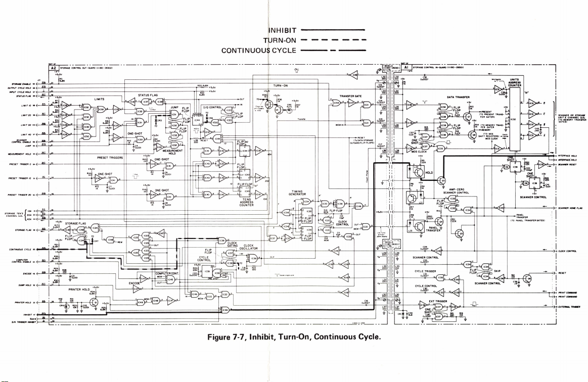
~·;.=.
:.;.
=:~
.;;;-
··-
·--------
--
f
lNHIBIT
CONTINUOUS CYCLE
----------
T~RN-ON
··j_
+.
~;.
I ·-·
__
_ __
.
z;-
-------
- - - - - - -
---
··
----
-
---
---- ---~
·
~~;
,;_--;;:-.;;;;;;;;;:-..;.;
E+--=
"--"<:i
c-+---
--"';;e.._~.i'--"><
,--·
:»H---
H
'+--------
--=--------
-'+---+-
+---
----!
i
I
:\,;~:
'::.;:.-·····
:j
___ ,._
i
-=-__,
I,_,, __
I
_,---~
I
.
i ••.
--=...;.
'
! .... _
.
~.:
::-.::
..
··
Figure 7-
7,
Inhibit, Turn-On, Continuous Cycle.
Page 48
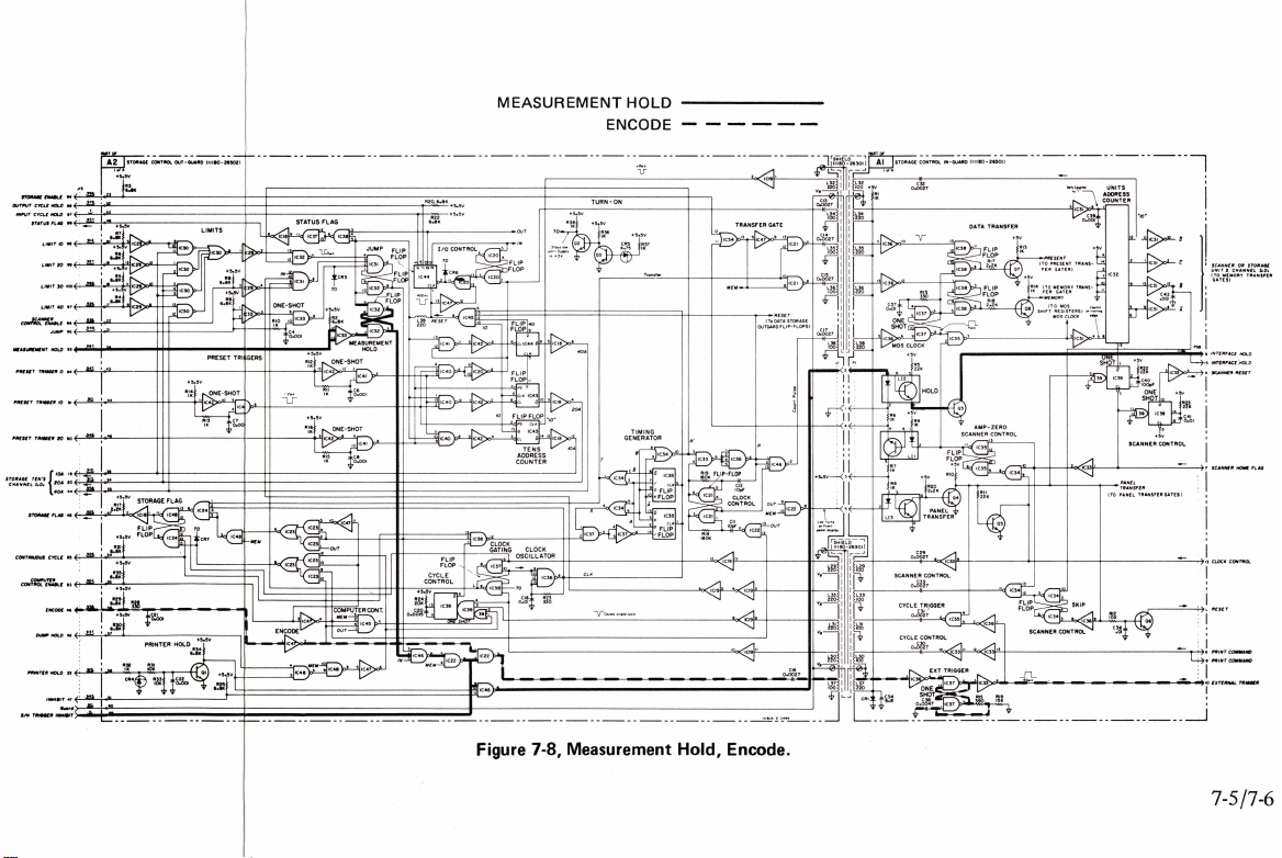
*·.;.= :
.
'
.:....--;;;;;;
:;_ ,
MEASUREMENT
HOLD
ENCODE
Figure 7-8, Measurement Hold, Encode.
e-+----+
~+---="'--
-"4•·1'-'<i•l'-f----------~
+---+--+----~
I
--->'j-"~-
1
'i .
...
"-..-->
'
! "···-
7-5/7-6
Page 49

STORAGE ENABLE
OUTPUT CYC
INPUT
CYC
STATUS FLAG
LIMIT
LIMIT
LIMIT
LIMIT
SC
ANNER
CO
NTROL ENABLE
MEASUREMENT
PRESET
TRIGGER
PR
ESET
TRI
LE
HOLO
LE HOLO
JU
MP
HOLO
GGER
----
STORAGE CONTROL OUT-GUARD (111
I of 4
+5
.5V
Jl3
I
~
94
~
88
f-'--'~'--.,-<>"'-------------------------+---------
.!,
87
<-'-~--'-<>'~------
~
89
I
10 98
20
30 100
40
~
m
99
~
~
97
~
96
I
~
95
~
93
23
52
53
48
19
17
22
21
24
R6
6.
8K
R4
6.8K
R3
6.SK
-
----------
-
----
80-26502
PRES
43
&1.L
0 84
+5.5V
Rl4
~
IO
91
44
IK
-
--
) I
--
--
--
+----------
ET
TRI
GGE
RS
1-2µ,s
--
-
--
- -
------
---
----
----
---
---------<>-+-
-
------.-"M~
LJ
I
-------1-
R20, 6.
'
"""~-+5.5V
8K
-+5
--
. 5V
--
- -
FLI
FLOP
--
is
P
PRESET
TRIGGER
STORAGE TEN'S
CHANNEL
I . O. 20A
I 4
STORAGE FLAG 48
CO
NTINUO
US
COMPUTER
CONTROL ENABLE
OU
PR
INT
S/ H TRIGGER
20
{'
OA
0A
CYCLE 85
EN
CODE
MP HOLD 92
ER HOLO
INH
IBIT 47
Guard
INHIBIT
90
H~
19
20
44
I
83
46
22
4=8
4~6
.:1..==
-'-<>
'----
~
36
34
35
+5.5V
Rl7
2.2K
~
47
+5.5V
R21
6.BK
54
~
~
~
~
~
~
~
..Q,
I
I
L_
55
56
57
58
51
60
59
+5.5V
R35
6.SK
+5.5V
R29
6.
SK
+5
R30
6
.8K
____
------1
R28
330
.5V
R
I K
C
C21
;i;o.00
32
R4
H-t
---------------+-t------
C48
I
2
1
+5.5V
t-
---
----~L_~
- -
-----
R
25
6. 8 K
-
-------
Rl6
1
C4
I
-------
+5.5V
IK
-<l>-"i
Rl5
IK
--
- -
--
--
--
, - -
Page 50

Model l ll
C32
0 .
0027
80A
Section
VII
------
-----
>
ET
-+---------------------r-r-~
TRIGGERS
-SHOT
-.f-----------------------.,-R_2~0N,6~
1-
2µ,s
,
•-B
_K+5•5V
1
;---+5.
5V
[!l_
___
___j
_____
R37
IK
Transfer
-l---------+------------t--t-----+------.,.--
40A
TIMING
GENERATOR
B
+-
R£S£T
(
To
DATA STORAGE
OUTGARD
FLIP-FLOPS
'--------+---------ir---++-----;
R'
CONTROL
Cl2
IOpF
CLOCK
R
OU
T
M£M
OU
T
)
c
~
0
(.)
i
I I I
: I I
:
ff111
1
"°"'4~
i
I
I I I
: I I
!
"
"~
\
Low
turns
on
Front
DATA
TRANSFER
~-------
11
11
'----+-+
-~
ll~
'---1-"-----+------.."0
AMP-ZERO
SCANNER CONTROL
11
-----.-~
fl<--
+--+--+--
~:-F---,=-'~
----+--1
-------+-._-
t5V
t---
- -
-------
PR£S£NT
(TO
PRES
ENT
FER GATE
(TD
MEMORY TRANS-
FER GATE
MEMORY
----J
-----
-+-----1~-
--
-1---
"10''
.-.:o;;-+-------
SCANNER
---
+5V
CONTROL
;~;i~F£R
(TO
PANEL
TRANSFER
GATES)
...,..
--r7s
15
A SCANNER
OR
MEM O
RY
HOLD
R£S£T
STORAGE
TRANSFER
SCANNER
UNIT s CHANNEL
(TO
GATES)
INTERFACE
INT£RFAC£ HOLD
SCANNER HOM£ FLAG
r.o.
-----------------
,
--
!
I
----
CLOCK
r----,.2.l___::O~S~C~l~L~L
----
- -
~A~
T~O~R:__+-J
----
-
---
--
------------t--------"1
CLK
-
----
- -
---
------
2
'o<:
1c19
-
---
~
13c_
__
10
--
-----
____j_
ll!S
_____
OA-
E- 24
0.
94
---
Cl6
0027
-++--~
SCANNER
CONTROL
C33
0.
0027
CYCLE TRIGGER
C31
0.
0027
CYCLE CONTROL
C
30
0.
0027
10
~-l--
h,
r;§_
Rl9
15K
----------------------
_n_
_.
__
~40~µ,'.'_•
_____________
___________
----...,..-:-7K
_,_71
PRINTCOMMAN
9
PRINT
0
£XT£RNAL
COMMAND
TRIGGER
I
D
_J
Figure 7-9. Control and Timing
7-7/7-8
Page 51

11 OVERRANGE I
10
N~-
-+--
-----+-+
-+-+
-"-f
-.......,
DAT
1
6
;;>l.:>"--'
~
--'&,"--t-7
6
fJ
20
Mode
l 1 l l 80A
[
[
[
[
1000
o?-i--+-------+-+-+-+-"'f-.......,
I
/00
80
K?-~
-.----
---
+-+-+-+-"'-r-
I
iii5
9<-~-~
I
-a
-...._
0
1
2
X
>"
'-"-37~---"-2==
=-7---'~34
40 o
RITY
+5V
G
ND
[
[
[
[
Bi
4
f-1-
------
I
-
-+-+-.!..f
[
[
[
[
[
[
R
lllBOA- E- 2493
t
DA
TA
Page 52

II OVERRANGE I
iO
N~C--
10
2000
I
ii
13
-+~~~~~~+-+-
+-+-"'l
Model
l l l 80A
1
~
J'2'-"-32"<>'
12
13
~=s923~H
13 A RANGE
Sec
tion
VII
o
12
10 28
35 8
9 1
000
000
4
2 15
14
I
I
I
I
I
~
29
..2Q!,.
25
28
c
8
RANGE
8
PSB
I
I
Ai
4
6
I
A
Bi
4
5 I
12
~
14
B RANGE
6
~
30
38
C RANGE
Al
SCANNER TE
CHANNEL r.o.
N'S
I
I
T
Bf-
~-..~~~
I
27
~
32 40 0
PSA
I
PO
LARIT
I
Y
10
~~
~+-
+-+-+-
'-=-1
a
I
2
I
8
STORAGE OR SCA
UNI T s
CHANN
NNER
EL r. o.
c
I
8
200
27
DI
040
00
B
+6
. S
VDC
,~)l-'L~~~~~
~
>"--~~~~
~~~~~~~~~t-~~~~~
~~~~~~~
~~~~~~
~~~~"'"<>-
~-'<>-;--~
J,~-r
-77
1
00
FUNCTION
9
0
;-~=
=4~+-7
31
80
tl
DA
TA
li
Figure
7-10. D
ata
Output
7-9
•'
.;
.:·~·•.
~
' I
Page 53

Appendix A
CODE
LIST
OF
MANUFACTURERS
Model l l l
80A
Code
No.
00000
U. S. A
00136
00213
00287
00334
00348
00373
00656
00779
00781
00809
00815
00853
00866
00891
00929
01002
01009
01121
01255
01281
01295
01349
01538
01589
01670
01930
01
960
02114
02116
02286
02660
02735
02771
02777
028
03296
03508
03705
03797
03818
03877
03888
03954
04009
04013
04062
04217
04222
04354
04404
04651
04673
04713
04732
04773
04796
04811
04870
04919
05006
05277
75
Common
McCoy Electronics
Sage
Electronics
Cemco, Inc
Humidial
Mictron,
Garlock
Aerovox
Amp. Inc. . . . . .
Aircraft
Craven,
Northern
Laboratories,
Sangamo
Pickens
Goe
Engineering
Carl
E.
Microlab
General
Capacitor
Alden
Products
Allen
Bradl
Litton
Ind
TRW
Semiconductors,
Texas
Instruments
Transistor
The
Alliance
Small
Parts
Pacific
Gudebrod
Amerock
Pulse
Enginee
Ferroxcube
America ..............
Wheel
ock
Cole
Rubber
Amphenol-Borg
Corp
........
Radio
Corp.
conductor
Division
Vocaline Co. of
.....
Inc
Hopkins
Hudson
Nylon Molding
G. E.
Semic
Dept.
Apex Machine
Eld
ema
Parker
Transitron
Pyrofilm
...............
Inc .
Singer
Co. ,
Flnderne
Arrow,
Elect.
Taruus
Arco
Electronic
Ess
ex
Wire
Hi-Q
Division
Precision
Pal
o Alto Di
Packard
Sylvania
Microwave
Dakota
Motorola
Prod.
Filtr
on Co. ,Inc.
Div.
Automatic
Sequoia
Precision
P . M.
Motor
Component Mfg.
Co.
Twentieth
Inc
...
W
est
inghouse
Semiconductor
The following code
to
Name) and
betical
codes have· been
their
numbers
latest
arbitrarily
supplements.
Manufacturer
. .
.....
Any
...
Corp
.........
. . . . . . . .
Co.,
Inc
......
Inc . .
..........
Corp
..........
Radio
Corp .........
Ltd . . .....
Engineering
Inc . . . .
Electric
Co. ,
Div
..........
Co .
Holmes
Corp
Inc . .
..........•
Electric
Co. ,
Dept
........
Co. .
ey
Co ...........
ustries,
Inc . .
, Inc . ,
Products
Mfg. Co
Inc
.........
Relays
, Inc ... . .....
Bros.
Silk Co
Corp ....
ring
Co ...
Corp.
of
Signals,Inc ......
and
Plastics
Electronics
........ ..
of
America, Semi-
and
Materials
...........
America
......
EngineeringCo
Tool
...
Corp
Seal
Resistor
Hart
Co ...... .
Corp
Co
Electric Products,
Engr
Inc.
Div. . . . . Phoenix,
Wire
..........
..
& Die . . . . . .
Corp
........
onductor
.....
...
& Tool
..........
Co .
........
Electric
Corp
Co. ,
Diehl
Div. ,
Plant
.........
and
Hegeman
..........
Inc
.......
............
of
Aerovox
Paper
Tube Co .
vis
ion
of
...........
Device
Div
. Inc
.........
Semiconductor
Western
Electric
Co
Co. . .
Coil
Spring
Comp
any ....
Service
Century
Plastics,
Electric
Dept ....
supplier
Mount Holly
.....
Rochester
..
. . Danielson, Conn.
.....
Colton,
Valley
stream, N.
Cherry
New
. .
.
Whitby,
.....
..
of
Livingston, N.
. Hudson
...
Beverly
...
Los
....
..
..
Santa
Saugerties
Long
Inc
..
.
..
Somer
,
..
Old
Saybrook,
....
San
~ringfield
......
.......
. .
.
Los
. .
..
Wakefield,
Cedar
Sumerville,
. .
Lambertville
Great
Los
..
Myrtle
....
. .
...
Mountain View,
Culver
Culver
. .
...
Redwood
. .
Westchest
W.
Bridgewater
... Los
Corp.
...
Bedford ,
Harrisburg, Pa.
Boonton, N.
Ontario,
:Bur
. . Pickens ,
Industr
Angeles, Cal.
Brockton, Mass
Milwaukee , Wis.
Lawndale, Cal.
Dallas,
Ang
Van Nuys ,
New
Roc
Branch,
9.mnyvale,
Broadview,
Fernando, Cal.
Newark,
Syracuse,
Compton,
Angeles,
Knolls,
Hartford,
Angeles, Cal.
. Wheeling ,
Palo
Northlake,
El
Angel~s
Youngwood,
.....
.... City
...... Los
.......
Inc .....
Div ...
........ Allianc
.........
Prod.
Co
.....
Hewlett-
.....
Co ... . .
~rings,
lington, Wis.
Dayton, Ohio
Beach, S.C.
Monte ,
are
from
assigned
Address
of
u.
, N. Y.
Calif.
Hill ,
N.
Mass
Canada
S.
y,
Falls,
N.
Hills,
Cal.
Texas
e,
Ohio
eles,
Cal.
Cal.
York,
N.Y.
kford,
Clara, Cal
, N.
N.J.
Cal.
ville
, N.
Conn.
N.
,
N.
N.
Calif.
Cal.
Mass
N.J.
N.
Conn .
, N.
Neck,
N.
Alto,
Cal.
Cal.
City,
Cal.
Arizona
City, Cal.
City, Cal.
Cal.
er,
, Mass.
,
Cal.
Pa
J.
J.
Cal.
J.
Y.
Ill.
Y.
Ill.
J.
J .
J.
Y.
J.
J.
Y.
Ill
Ill.
Ill
Pa.
the
S.
Y.
C.
.
The
.
.
.
.
Federal
Supply Code for
date
of rev
ision
to
Code
No.
05347
05397
05574
05593
05616
05624
05728
05729
05783
05820
06004
06090
06175
06402
06540
06555
06666
06751
06812
06980
07088
07126
07137
07138
07149
07233
07256
07261
07263
07322
07387
07397
07700
07829
07910
07933
07980
08145
08289
08358
08524
08664
08717
08718
08727
08792
08806
08984
09026
09097
09134
09145
09250
09353
09569
09795
09922
10214
10411
10646
suppliers
and the date of the
not
appearing
Manufacturer
Ultronix,
Inc. .
Union
Carbine
Div. . .
Viking Ind. Inc
Icore Electro
Cosmo Plastic
~ec.
Barber
Tiff
. . . . . . . . .
Metro-Tel
Stewart
Wakefield Engi
Bassick
Warner
Raychem
Bausch
Co. . . . . . . . .
E.T.
America .....
Amatom Elec
Co. , Inc . . . . . . . . New
Beede Electrical Instrument
Co.,
General Devices
Components
T
orrington
Varian
Kelvin
Digitran
Transistor
Corp ... . .
Westinghouse
Corp.
Filmohm
Cinch-Graphik
Silicon
Avnet
Fairchild
Semiconductor
Minnesota
Birtcher Corp, The
Sylvania Elec
Mt. View
Technical Wire
Inc. . . . . .
Bodine
Continental
Raytheon Mfg. Co. ,
condu
Hewlett-Packard
New
U.S.
Blinn
Burgess
Deutsch
Bristol
Sloan Company . . Sun
ITT
Phoenix
National Radio
CBS Electronics
Operations
General
Miniature
Mel-Rain
Babcock
Elect
Texas
Tech.
El
ect.
Electro
C
& K Componen
Mallory
Canada, Ltd..
Pennsylvania
Burndy Corp.
General
Corp.
Ti-Tal
Carborundum
-Plastics
Co.) . . . . . . . . . . . .
Colman
en
Optical
Roslyn
Corp .............
Enginee
Co. , Div.
Corp.
Corp
and
Lomb
A.
Produ
tronic
Inc. . . . . . . . . . .
Inc.
Mfg.Co. ,West
Assoc.
Electri
c_ Co. . . . . Van
Co ....
Electroni
....
Electric
,Electronic
Corp
Transist
Corp
. . .
Came
Rubber
t.
Operations
Elect.
Co. . . . .
Device
ctor
Div
Jersey
Division.
Enginee
ring
, Delbe
rt
Batt
ery
Fastener
Co. , The . . . . . . . .
Cannon
Electric
Div. . . . . . . . . .
, Div.
Electric
Lamp
Relays
ronic
Enclosures
Capacitor
Ind. Inc. Atohm
..
Assemblies,
Battery
Florocarbon. Clifton
. .
Tran
sistor Western
,Inc ...
Co.
Manufacturers
Corp., Elect.
...........
(c/o
Co. .
Co. .
ring
neering
of
. .
...
......
Optical
cts
Co. of
Co. , Inc
,Ariz.
Etmac
...........
.
Tube Div .
. . . . New
Co. .
or Corp . . . .
ra & Inst.
Div
..
Co
Prod
Products
Corp
.........
Co.,
Co .
Co
.........
Co
..
.
Niagara
Corp
Lab.Inc
Semiconductor
of
Co.
Dept. . . .
Div
......
Co. . . . Houston ,
ts
Inc
Co. of
supplements
in the
H4
Handbooks.
..... New
Inc
......
Electrical
..
Hei
ghts,
Co. .
.... Santa
Inc ...
Stewart
....
. Redwood
Hardware
.....
Div
...
Div .
Div
.....
cs
. Minn
....
City
...
Corp.
Mou
......
. .... .
Monter
. In
c.,
..
Mountain View 1 Cal.
......
Semi-
Mou
....
. . L
Falls,
. .
...
Inc. ,
....
...
CBS Inc
.... Lowell, Mass
,
...
...
. . .
Inc
... Los
Inc ..
.....
. .
Toronto,
. ...
Niagara
Cataloging
..
San Mate
Canoga
Sunnyval
Cleveland
...
Long
Westbury
..
Wakefield ,
Bridgeport,
..
Rochest
. .
Rochell
Penacook,
Indianap
Phoenix, Arizona
..
Van
San
Pasadena,
eapolis,
....
of
Indus
Carle
Culver
,
ntain
Minn
eapolis,
ey
Cranford, N.J
Hawthorne,
ntain
Rockaway ,
os
Angeles,
. . .
Pomona, Cal.
Ontari
Los
Angeles, Cal.
Waterbury, Conn
Phoenix,
Paramu
Cleveland
Indiana
Costa
.Angel
.
Burbank, Cal.
. .
.Newton ,
Ontario, Canada
Heig
Norwalk,
Los
Angeles,
Berkeley, Cal.
Handbooks H4-1 (Name to Code)
used
appear
at
the bottom of each page. Alpha-
o,
Cal.
e,
Cal.
, Ohio
Ill.
N. Y.
,N. Y.
Mass.
Conn.
Cal.
Y.
Ill.
N.
Y.
N.
H.
s , Ind.
Cal.
Cal.
Cal.
Minn.
, N.
Y.
N.
Y.
Cal.
N.
Y.
Cal.
Cal.
Minn.
Cal.
Cal.
N.J.
Cal.
Cal
N.J.
, Ohio
Ind.
Cal.
Calif.
Texas
Ill.
Mass.
Conn.
Cal.
Y.
Code
No.
11236
CTS of
11237
Y.
.
.
.
Chicago
11242
Bay
Teledyn
11312
National
11314
Precisi
11453
11534
Duncan
11711
Gen
Imperial
11717
11870
Melabs,
12136
Philadelphia
12361
Grove Mfg.
12574
Gulton Ind. Inc.
Clarostat
12697
Elmar
12728
Nippon
12859
12
881
Metex
12930
Delta
12954
Dickson
13019
Airco
13061
Wilco
Thermolloy
13103
13
327
Solitron
Telefunk
13396
Midland-Wri
13835
14099
Sem-Tech
14193
Calif.
14298
American
33
ITT
144
14493
Hewlett-Packard
14655
Cornell
14674
Corning
14752
Electro
14960
Williams
15106
The
15203
Webster
152
87
Scionics
15291
Adjustable
Micron
15558
Amprobe Inst.
15566
Cabletronics
15631
15772
Twentie
15801
Fenwal
15818
Amelco
16037
Spruce
16179
Omni-Spectra Inc.
16352
Computer
Electroid
16554
16585
Boots
16688
Ideal Pree.
De
16758
Delco
17109
Th
17474
Tranex
Hamlin Me
17675
Angstrohm
17745
17856
Siliconix In c. . . .Sunnyvale,
17870
McGraw-Edison
Power
18042
Cle
18083
Signetics
18324
Ty-Car Mfg. Co . ,Inc. . .
18476
TRW
18486
Chomeri
18565
Curtis
18583
186
12
Vishay
E.
18873
Durant Mfg. Co . . ... Milwaukee, Wis.
18911
The
19315
Control Div. .
19500
Thomas
Div.of
Concoa.
19589
Address
York, N.
Park, Cal.
Rockford,
Island,
Cruz, Cal.
City,
er, N.
Chicago,
e,
oli
Nuys,
Carlos, Cal.
Nuys,
Elmira
York,
try,
Place,
City,
View ,
Park, Cal.
Chicago, Ill.
View ,
o,
Canada
Valley,
Arizona
s,
polis,
Mesa,
es,
Chicago,
hts
, Penn.
Falls, N.
and
H4-2 (Code
Manufacturer
Berne
, Inc.
Telephone
California,
State
e Inc. ,
Div
....
on
Electronics
eral
Instrument
Semiconductor
Group
Inc. . .
Div. . Albuque
Filt
Electric
Electronics
Semiconductor
Electronics
Supply Co. , Inc. . ... Wit
Produ
Devices
en
Pacific
lndustries
Res
Semiconductor , a Div. of
Int.
Tel
ephone and Tel
Corporation
Dublier Electric
Glass
Cube Inc . . . . . . . San
Sphere
Electronics
Corp.
Electronics
th
Spring Co . . . . Santa Cl
Elect.
Inc. . . Mountain View ,
Pine
Aircraft
Jur
Meter
Radio Div. of
ermonetics
Company
Design
vite
Corp.
Elect.
cs
Ins
Instruments
I.
DuPont and Co. , Inc . .
Bendix
A.
McGraw-Edison
of
Inc . .
....
Electronics
Seal
Connector
Electronic,
Co.,
Mfg. Co. . . . .
er
. . . . .
(GmbH) . Han
. . .
istor
Components,
Mfg. Co. . . . San
Co.
Bushing
Century
Diode
Co. . . Union ,
Meter
tal
Pree
Corp.
Comp.
trument,
Corp.
Edison
Corp.
Microwave
Corp
.....
Inc. . . .
Corp.
,
Division
Products
Inc
..
Handle Co.
Inc
...
,Data
System
Cor p . . .
Co. ,
Ltd
. .
Corp
. . .
Inc. Newport
Corp.
cts
Inc. T
ght Div.
of
, Inc
....
......
Corp
. .
Inc
egraph
... West Palm
Company
.....
Works
. . . . .
Inc.
Mica
Inc. Canoga
Products
Pacific Inc. . ....
Semiconductor
. .
Corp
. . .
......
,Inc.
Co
......
. . .
Co
...
. .Garden
Corp
. . . . .
Coil
Co .
....
Corp.
Nut
Corp.
Co. ,Inc. ,
Div. Brooklyn,
G.
M.
Corp
..
Corp.
. Inc. . . . No. Holl ywood,
Co. . .
Div.
Inc .
Inc.. .
, Navigation &
Industries,
.
So.
Pasadena, Cal.
...
Waltham
Palo
. . .
.....
Downey,
Jamaica,
Costa
Newark,
. .
Buena
. .
Palo
. .
Camden,
Shady
Dover,
..
W.
Haven, Conn .
...
..
Tokyo,
Scottsdale,
chita,
.
..
Detroit,
..
Dallas, Texas
appan,
over
Kansas
City,
Newbury
Santa
Monica ,
...
Conshohocken ,
Loveland, Colo.
Newark
Cornin
Gabriel,
. .
Little
New
York, N.
Northridge,
..
N.
Hollywood ,
City
, Long Island,
Lynbrook,
..
Costa
Framingham,
..
Spruce
. . .
Detroit,
.
..
Pasadena,
....
Kokomo, Ind.
Mountain View,
. . . .
Manchester, N.
Palo
Div
..
Palo Alto, Cal.
. . . . Sunnyvale ,
..
Holliston, Mass.
Des
Plaines
Plainville, Mass.
.Mt.
Malvern,
..
Wilmington
.. Teterboro,
..
West
Orange,
Baldwin Parl;t,
Address
Berne,
Ind.
, Mass.
Alto,
Cal.
Cal.
N. Y.
Mesa, Cal.
N.J.
Park, Cal.
Alto, Cal.
N.J.
Grove, Pa.
rqu
e,
N.
N. H.
Japan
Clark
, N.
Beach,
Cal.
Arizona
Kansas
Mich.
N.
,Ger
many
Kansas
Park,
Cal
Cal.
Pa.
Beach,
Fla.
, N.
g,
N.
Cal.
Jose, Cal.
Falls, N.J.
Cal.
Cal.
N.
N.
Mesa,
Cal.
ara,
Cal.
Mass.
Cal.
Pine,
N. C.
Ill
Lodi,
N.J.
N.J.
Cal.
N.
Park,
Cal.
Cal.
Akron
, Ohio
Cal.
Cal.
Alto,
Cal.
Cal.
, Ill .
Kisco,
N.
Pa.
, De
N.J.
N.J.
Cal.
j
1
M.
J.
Y.
.
J.
Y.
Y.
Y.
Y.
.
Y.
H.
Y.
l.
j
00
015-49
Revised
: May, 1970
From:
Handbook Supplements
H4-l
Dated
January
1970
Page 54

Model l l l
80A
Appendix A
:1
·.
1
·· 1
· l
J
Code
No.
LRC
19644
19701
Electra
General
20183
21226
Executon
21355
Fafnir Bearing
21520
Fan
23020
General
23042
Texscan Corp.
23783
British
24455
G.
24655
General
24681
Memcor
26365
Gri
26462
Grabert
26851
Compac/Hollister
26992
Hamilton
28480
H
28520
He
30817
In
33173
G.
35434
Lectrohm
Stanwyck
36196
36287
Cunning
37942
P .R.
Mec
39543
40920
Miniature Precision
Honeywe
40931
42190
Muter
43990
C. A.
44655
Ohmite Mf
Penn En
46384
47904
Po
48620
Precision
Microwav
49956
52090
Rowan
52983
HP Co. , Med .
54294
Shallcross
55026
Simpson Electric Co. .
Sonoto
55933
Raytheon Co.
55938
56137
Spau
56289
Sprague Electric Co.
58474
Superi
Telex
59446
Th
59
730
Triplett
60741
61775
Union Switch
W
62119
Universal
63743
Ward-Leonard
Weste
64959
65092
Weston
66295
Wittek Mfg. Co. .
66346
Minn
Allen
70276
70309
Allied
70318
All
10417
Amplex
70485
Atlantic
Amperite
70563
70674
ADC
70903
Belden
70998
Bird
71002
Bi
71034
Bliley
Boston
71041
Bud
11218
Cambridge
71279
71286
Cam
71313
Cardwe
71400
Bussmann
71436
Ch
Calif.
71447
CTS
71450
ITT
71468
Cine
71471
Manufacturer
Electronics
Mfg. Co.
Atronics
e , Inc. Long
steel Metallurgical Corp ....
E.
es
ewlett-Packard
yman Mfg. Co. . . .
strument
Inc.
E. R
Ltd.
Ltd.
hanical
Norgren
laroid
Inst. Co.
&
Syste
lding Fibre Co.,
omas & Betts
es
tinghouse
esota
Reve r e Mincom
metal
. . . . . . . . . . .
Products
Electric
rnba
Murray
Radio,
loc
M
cGraw
icago
Corp.
Cannon
ma,
Co. ,
Reed
Co. .
Radio
Electronics
Lamp
Division, Nela
Radio
Co .......
Inc. ,
Comp.
Reproducer
File Co.
Watch
Co. Lan
Specialties Co. ,
ece
iving
Tub
Inc. .
Coil
Products
ham,
W.
.
.......
Mallor
y & Co.
Indu
stries
ll
Inc ........
Co. . . .
Co.
g. Co. . . Skokie,
g.
&Mfg.
Corp.
Thermometer
e &
Power
Controller
Elec.
Mfg. Co . . .
ne
Corp.
Commercial
m Div. . . So. Norwalk
or
Elect.
Co. .
Corp.
Electrical
and
Air
Electric
Electric
rn
Electric
Inst.
Inc. Weston-Ne
Mining & Mfg. Co.
Mfg. Co .............
Control
Screw
Produ
. Div. of
India
Rubber
Co . , Inc. Union
Inc. . .....
Mfg. Co. . . .
Corp
ch
Radio
Co. New York,
Electric
Co .
Gear
Works
Co. of T
Inc. Willou ghby, Ohio
Thermionics
Fastener
ll
Condenser
Mfg. Div. of
-Edison
Condenser Corp. . .....
Spr
ing Co. , I
Electric
Div.
Aerovox
......
Horseheads,N.
Corp.
of
Co. Palo
.............
H.
Corp.
Co
Co
Signal Div. of
Co. , Inc. New
Di
Chrysler
exas
Corp.
Co. St. Lo
Independenc
Philadelphi
The
Div. .
Corp.
America, Inc. Carlstadt,
Co. .
e Dept.
Hawkesbur
& Hill
,Inc.
Bearin
Tube
.....
.
..........
Inst.
Brake
Co. .
v. . ... St.
..........
,Inc.
Div. of
Corp.
nc.
Inc.
Island
New
Britian
N.
....
..
Metu c hen , N. J.
. .
Indiana
Ltd
...
Was hington ,
Park
, Cl
. W
est
Concord, Mas
....
. Huntin gton,Ind.
. New Rochelle ,
...... Holli
...
. Ke
nilworth, N.J.
.Little Falls,
.... Owens
!
y,
Ontario, Canada
1
Tor
ont
o,
Ontari
. .
Indianapolis
Prod.
Co. . .
gs
,Inc
.. Kee
...
Minn
eapolis,
En
glewood,
.
..
Doyl
.
..
Cambridge, Mass.
&
Southampton, Pa.
Div
...
Waltham, Mass.
...
Westminst
Div. W
........
Inc
.....
.........
Co. Bluffton, Ohio
Co ... Mt.
ct Co. , Inc .
Work
Corp.
. .
Lindenhur
.
Corp
altham, Mas
Elm
Apparatu
s
Ton
North
Adam
Bri
.
..
Eli
Co. . .
Pittsbur
.. Owosso,
wark.
...
Hartford
...
New York,
Gard
Corp.
. Detroit, Mich .
s,
Inc
...
. Minneapolis , Minn .
Cl
.
Quince
Cambrid
P
st,
Pico-Rivera, Cal.
......
..
Los
..... Bu
Address
e,
Kansas
a ,
Pa.
City , N.
, Conn.
Chi
cago,
Ill
polis,
lnd.
D.C
eveland, Ohi
N.
N.
ste
r ,
Cal.
caster,
Pa.
Alt
o,
Cal.
N.J.
boro
, Ky .
Chi
cago,
Ill.
o,
Canada
, Ind.
Akr
on , Ohio
ne ,
N.
Minn.
Chicago
, Ill.
Colo.
Ill.
estown,
Pa.
er , Md.
Selma, N.
Chicago,
Ill.
sford,
N.
, Conn.
awa
nda,
N.
s, Mass
stol , Conn.
Tulsa, Okla.
zabeth,
N.J.
gh ,
Pa.
Mich.
Vernon, N.
York,
N.
Newark, N.J.
Chica
go,
Ill.
Pau
l , Minn.
, Conn.
N.
en
Cit
y,
N.
Chicago, Ill.
City,
N.
Chica
go .
land, Ohio
. .
Erie, Pa
y,
Mass.
ge ,
Mass.
L.I., N.
uis
. Mo.
Chica
go,
Elkhart
, Ind.
rbank, Cal.
111.
N.
N.
Ill.
Cal.
eve
aramus.
Angeles,
CODE
LIST
Code
No.
71482 C.
Y.
Y.
.
.
o
s.
Y.
J.
H.
s .
C.
Y.
Y.
.
Y.
Y.
Y.
Y.
J.
Y.
.
J.
Y.
P.
71590
Centralab
Globe Union Inc. .
71616
Commercial Plas
71700
Cornish
71707
Cot
71744
71785
71984 D
72136
72619
72656 I
72699 Ge ne
72765
72825 Hugh H. Eby Inc.
72928
72962
72964
72982
73061
73076 H. M.
73138 He
73293 Hughes Prod
73445
73506
73559
73586
73682
73734 Fe
73743 Fischer Special Mf
73793 Ge
73846 Gosh
73899
73905
73957 Groove
74276
74455 J .
74861 Industri
74
74970 E.
75042 Inte
75263 K
75378
75382 Kulka
75818 L
75915
76005
76210 C. W.
76433 Gene
76487
76493
76530
76545
76703
76854
77068 The B
77075
77221
77252
77342
77630
17638
77764
77969
78189
78277
78283
78290
o Coil Co . , Inc.
Chica
Cinch
H
oward
ow
Electro Moti
Diali
ndiana
Electroni
Cap
Drake Mfg. Co. Ha
Gudeman
Elasti
Robert
Eri
e Technological Produ
Hans
lip
Hugh
Amperex
Bradley
. . . . . . . . . . . . . . . . . . . . New Haven , Conn.
Carlin
Circle
George
Div. MSL Indus
deral
neral
JFD
Jennin
Signalite
H.
868 R.
F.
Amph
F. Johnson
rnational Res
eystone Car bon Co. , Inc. . St.
CTS
enz Electr
Littlefuse, In
Lord Mfg. Co. . .
Micam
Jam
es
J.
W.
Cinch-Monadnock
Fast
Mueller Electric
Nationa
Oak
Manufacturin
Electrod
Pa
cific Meta ls Co. .
Pha
ost
Electronic
Philadelphia
Wire
Ameri
Potter & Brumfi
TRW
Gene
Rectifier
R
esistance
Rubbe
Shakeproof
Illinois
Sigma.
Signal
St
ruth
OF
MANUFACTURERS
Manufac
tur
er
Clar
e & Co.
Div. of
Wir
go Min
Mf
g.
B. J on
Corning Corp.
............
ght
Corp
Genera
cs
ral Instrume
Divi
sio
Co. .
c Stop Nut
M.
Hadl
en Mfg. Co. , In c. .
Harp
er Co
ot Div.
. . . . . . . . . . .
es
Aircra
Ele
Semiconductor Corp
g El
ectric,
F Mfg. Co
K.
Gar
Screw
Ind
ustries
en
Stamping & Tool
Electronics
gs
Radio Mfg.
-Pin
lnc . .
Winns,
al
Condenser
Products
eno
l-B
Knig
hts,
El
ectric
Marw
ede
ral
Ins
trum
old
Division
Mill
en Mfg.
Miller Co. .
ener Corp.
l Union
endix
Corp.
ynami
ran
Ins
Corp.
can
Machine &
Electroni
ral
Instrum
Div
Products
rcraft
Divi
Tool Works .
. . . .... So.
Indi
cato
ers-Dunn Inc.
... ...
tics
Co
e Co. , The
iature
Co.,
ve Mfg. Co. , In
. . . .
Div. .
n.
of Bec
ucts
ct. Co. . . Hicksv
Corp.
and
or g
Inc
ic Mfg. Co . .
c.
trument
Co . So.
Steel and
Corp.
........
.....
Lamp Works ...
es
Div.
...
l Co
rp.
,
........
nt
Corp.
Corp.
ey
Co. .
....
cts,
.............
kman
Inst. , In
Division
ft Co
....
Inc.
...
rett Co. ,
trie
s1 Inc..
Products, Inc.
g. Co.
Co. , The .
Co
Corp.
Corp.
. . . Ridge
Sons Win
Corp.
Division
of
Electr
oni c
Co. . . .
istan
ce
Co.
............
Corp
.......
l
....
ent
Corp.
.........
Co.,
Inc.
... Los Ange
, Div. of Unit
Co. . .
......
g Co. .
,
cs
Div.
.....
and
.
....
Foundry
eld Div . . . .
c Compone
isi
r Corp.
ent Corp. ,
on .
Co.
of
Calif.
sio
n of
nts
of
.
...
Chica
. Milwaukee , Wi
Chi
New York, N.
Provid
ence , R.
Chi
.Chicago,
. . Midland, M
c.
Willimantic
... Brooklyn ,
Keasb
·
Newark1 N.J.
rwood
Heights, Ill.
Philadelphia,
...
Chica
.
Union,
Los Angel
Inc . .
..
...
Princeton
Chicago, Ill.
c.
...
Fullerton, Cal.
Newpo
rt
Beach,
ill
e,
L.
.
Hartford,
. .Trenton, N.J.
Philadelphia1 Pa.
.Chicago, Ill.
Cincinnati1 Ohio
....
Elyria
......
Goshen
. .B
rookl
San J
field, N.J.
.Neptune,
chester, Mass.
.Chicago,
Corp.
Danb
ury,
...
Waseca, Mi
Philadelphia, Pa.
Mar
Sandwich ,
Mt. Vernon,
....
Chicago, 111.
.
Des
Plaines
San
Francisco, Cal.
N
ewa
Malden, Mas
ed
Carr
. San
Leandr
Cleveland, Ohi
New
.Crystal Lak
N.
Hollywood, Cal.
San
~ran
cisco,
Pasadena, Cal.
Philadelphia
Co.
Princeton
Div.
Camden, N.
...
Brooklyn, N.
Harrisburg, Pa.
...
Torrance, Ca
..
Elgin, Ill.
Braintree, Mas
New York,
Pitman, N.J.
(Continued)
Addr
ess
go,
111.
s.
cago,
Ill.
Y.
I.
cago
, Ill.
Ill.
ich.
, Conn.
N.
Y.
y, N.J.
Pa.
go,
Ill.
N.J.
es,
Cal.
Eri
e,
Pa.
, Ind.
Cal.
I.
,
N.
Y.
Conn.
, Ohio
, Ind.
yn ,
N.
Y.
ose, Cal.
N.J.
Ill.
Conn.
nn.
ys,
Pa.
Ill
.
N.
Y.
, Ill.
Erie, Pa.
rk1 N.J.
s.
les, Cal.
o, Cal.
o
ark, N.
J.
e ,
Ill.
Ca
l.
, P
a.
, Ind .
J.
Y.
l.
s.
N.
Y.
Code
No.
78452 Thompson-Breme
Tilley Mf
78471
78488
Sta
78493
Standard Thomson
78553
Tinnerm
78790
Transform
78947 Ucinit
79
136 Wald
79142 Veeder R
79251 Wen
79727 Co
79963
Zierick Mf
80031
Me
80033
Pres
80120 Sch
80131 Elect
Standard
any m
80207 Uni
Corp.
80223 United
80248
Oxford
80294
Bourns Inc.
80411 Arco
80486
All
80509 Avery
80583 H
ammar
80640
Stevens, Arnold
imeo
80813 D
81030
Internati
810
73
Grayhill
Triad
81095
81312 Winch
Milit
81349
81483 Int
81541
Airpax Elec
81860
Barry
82042
Carter Prec
82
047 Spe
Electri
82116 Electri
82142 J effe
Speer
82170
Fair
Space
82209
Magurie
82219 Syl
Electronic Tube
823 76
Astr
82389 Switc hcr
82647 Me
Spencer
82768
Phillips-Advance
82866 R
ese
82877 Ro tton' Mfg. Co. , Inc.
82893 Vector Elect
Carr Faste
83058
83086 New H
Bear
83125 Ge neral I
Capacitor Div..
83
148 ITT
83186 Victo
endix Corp
83298 B
83315 Hubbe
83324 R
osa
83330
Smit
83332 Tech
83385
Central
83501
Gavitt
Amera
83594
Burrou
Tube
83
740 Union
Pr
77
Model
837
83821 L
oyd Scruggs
83942 Aero
84171 Arco Electronics Inc...
84396 A.
84411 TRW
Manufac
r & Co. Chi
g. Co. San Fran
ckpole
Carbon Co.
an
e Co. . .
es
Kohinoor In c
co Mfg. Co. Chi
ntinental-Wirt
pco
Divis ion of
tole Corp. Tol
nitzer Alloy
ronic
anufac
max
Switch , Div. Maxon
Transform
Electric
Div. of
Star Produ
Labe
lund Co. , Inc. .
Gra
ona l In
Tran
es
ter
ary
ernatio
Controls
rti
Farada
c Div. . . Hobok
c Regu l
rs Elect
Carbon Co
chil d
& D
vania
on
Corp..
aft
tal
s &
arch
ampshire
ing,
Wire and
r y Eng. Corp. . . .
ll
Corp.
n In
c.
h, Herman H., Inc .
Labs
Screw Co.
Wire
ce
ghs
Div..
Carbide
od. Div. . . .
Eng.
nautical
J. Glesener
Capac
Corp
Products
er Engineers
oot
, Inc
.........
Electr
.
.......
g.
Corp.
Sessions
Products
Industries
tube
or
semi-conductor
turer.
er Co
Corp
Robertshaw Contr
cts
Inc . .
l Co. Monr
, Co. , Inc. . .
y Co. . . . . . . . . . Dayton , O hio
st. Inc.
Co
...........
sforme
r Corp. Venic
Elec.
Div.
Specification
nal
Rectifier Corp.
tronics,
, Div.
ision
Electric
y Inc. , Copper H
ator Corp.
r on
ics
Divi
. .
Came
ra
& In
efense Sys
Indu
stries,
Electric
Prod.
Divi
.East
, Inc.
Contro
ls Inc. ,
Products.
Contro
Products
Corp. . ...
roni
c Co. .
ner Co. . . .
Ball
Inc .
.........
nst
rum
ent Corp
.
Cab
le Div
. , Red
Bank
.....
and
Cable
Corp
.
Corp. , Electronic
Corp. 1 Consumer
and
Mfg. , Inc
Co. . .
Inst.
& Radio Co. .
Co. , Inc . . San
itor
Div. .
turer
. .St. Mar
....
..
, Inc.
...
Association.
........
Inc
tems
Inc. . . Greenwi
Waltham
Cleveland
....
San
...
oni
.
rp
Litt
..
Barry
sion
.......
st.
, Inc.
sion
Newark
l Co. .
..... Los Angeles,
.
...
Co.,
Gabri
. Newtonville, Mass.
Long I
sland City, N.
. Hartf
cs
Corp.
....
Philadelphia, Pa.
New Rochell
Clock
Co.
...
. Mo
rri
Co.
Elizabeth, N.J.
device,
Electronics
.
Wallin
...
. New York,
. . Chi
Riversid
ols Co.
Columbus,
...
Defian
...
Mars Hill, N.
Boston
. . Orange, Conn.
....
LaGrange,
on Ind
.,
Oakville,
El Segundo , Ca
Cambridge
Wri
ght
Watertown
Co . . . Skokie,
ewitt
Norwa
of
..
Du
Corp.
Div. .
Paramus,
..
Emporium, Pa.
, Harrison,
Attleboro
Madis
Woodst
..... Glen
Cambrid
Pe terbor oug
. ,
Darlin
Sprin
Div
... Red
. . Mundel
Newpo
rt Beac
Br
ooklyn, N.
Palisades
Div. of
Bro
okfield,
.
... Plainfie
New
....
Huntington , Ind.
...
. .
Great
Francisco, Cal.
... Oga11al
Address
cago,
cisco,
Cal.
ys,
, M
ass.
, Ohio
el,
Cal.
or d, Conn.
cago,
e,
N.
s town,
N.
edo,
Ohio
gford, Conn.
N.
cago, Ill
e,
Cal.
Ohio
ce,
Ohio
ovia, Cal.
, M
ass
e,
Cal.
Inc.
Conn .
, M
arylan
Cor
p.
, M
ass
en,
N.
lk , Conn.
Bois, Pa.
N.
ch,
Conn.
N.
Chicago, Ill
, Mass.
..
Joliet, Ill.
on ,
Wis.
ock ,
N.
dal
e, Cal.
ge, Mass
h,
N.
gto
n, S. C.
Cal.
gfi eld, N. J .
Bank, N.J.
ein,
111.
h,
Cal.
Park,
N.
Chicago,
Ill
Mass.
ld ,
N.J.
York,
N.
Festus
, Mo.
Lod
i,
N.
Neck,
N.
a,
Neb.
Ill.
Pa.
Y.
111.
Y.
J .
Y.
C.
Ill
Ill.
J.
J.
Y.
H.
Y.
J.
Y.
J.
Y.
.
.
.
l.
d
.
J.
.
.
.
00015-49
Revised: May.
1970
From:
H4-1 Dated
Handbook Suppl
January
eme
nts
1970
Page 55

Appendix A
CODE
LIST
OF
MANUFACTURERS
(Continued)
Model l
ll
80A
l
No.
94870
Barkes
Boonton Molding
85454
85471
A. B. Boyd
85474
R.
85660
85911
86174
86197
86579
86684
86928
87034
87216
87473
87664
87930
88140
88220
88698
89231
89473
89479
89665
90
90179
90365
90763
90970
91146
91260
91345
91418
91506
91637
91662
91673
91737
91827
91886
M.
Koiled
Seamless
Fafnir
Clifton
. . . . . . . . . . . . . . . . . . .
Precision
Radio
& Devices Division . . .
Seastrom
Marco
Philco
. . . . . . . . . . . . . . . . . . . . . . .
Western Fibrous
. . .... . • . .
Van
Tower
Cutler-Hammer,
Gould-National Batteries,
eral
Gen
Graybar
G.
E.
ur
Sec
United
United Shoe
030
U.S.
Plastics
Belleville
. . . . . . . . . . . . . . . . . . . . . . .
United
Bearing
ITT
. . . . . . . . . . .
Connor
Miller
Radio
Augat
Dale
Elco
Epipho
Gremar
K F
Malco
Manufacturer
Tarzian,
Inc
.....
Company
Co
..........
Bracamonte & Co
Kords,
Inc. . . . . . .
Rubber Co. .
Bearing
Co. . . ....
Precision
Products
Rubber
Corp.
Industries
Corporation (Lansdale
Waters & Rogers
Mfg.
Distributing
ity
Transformer
Rubber
Carr
Cannon
~ring
Dial & Nameplate
Materials Co. .
Inc. .
Electronics
Corp
ne Inc .
Development
Mfg. , Inc
Products
of
America, Electronic
Mfg. Co. . . . . . . . . .
. . . . . . . . . .
Glass
.........
Corp.
Inc. .
Mills
, Inc ...
Electric
Co
..........
Corp
Co .
•..............
Co. .
Machinery
Co . ,
Consumer
Prod
. Div
..........
Speciality
Engineering
...•..........
Mfg. Co.,
Tool
Fastener
Elect. Inc. , 5alem
• . . . . . . . . . . .
Mfg. Co
.............
, Inc
............
Inc. .
Co
......
..............
..
. Bloomington, Ind.
....
..
San
....
San
..
...
. . . Chicago, Ill.
Los
Co. , Inc.
Clifton
Corp.
..
. . .
Division)
Products
San
Inc
...
San
. . .
..... Providence,
........
Inc
•..
......•.
.....
Schenectady,
.......
Corp
. . . .
Ind. &
Mfg
.,
Inc.
Corp
. . .
....
....
.....
Co.
....
...
San
Div.
san
. . .
. . . . Chi
Attleboro, Mass
...
Columbus, Nebr.
Willow
New
Wakefield,
Redwood
Co
....
Address
Boonton, N.
Francisco,
Francisco,
Hamden, Conn.
Angeles, Calif.
Harrison,
Anaheim,
Co.
Francisco
Francisco, Cal.
St.
Detroit,
Beverly, Mass
Belleville,
Fran
Francis
El
Cal.
Cal.
Heights, Pa
Dayton,
Ohio
Comp.
N.
Glendale,
Cal.
Cal.
Lansdale, Pa.
, Cal.
R.
Lincoln,
Ill.
Paul
, Minn.
Buffalo , N. Y.
Oakland,
Cal.
N. Y.
Mich.
Chicago, Ill.
Passai
c,
N.J
Ill
Chicago,
Ill.
cisco,
Cal.
Salem,
Mass
co,
Cal.
Monte ,
Cal.
cago,
Ill.
Grove
,
Pa.
York, N.
Mass.
City,
Cal.
Chica
go,
Ill.
Code
No.
91929 Honeywell
J.
.
J .
I.
.
.
.
.
.
Y.
. . . . . . . . . . . . . . . . . . . . . .
91961
Nahm-Bros.
92180
Tru-Conne
92367
Elg
92607
92702 IMC
92966 Hudson
93332
93369
93410
93632
93929 G.
94137
94144
94148
94154
94197
94222 South
94330
94375
94682
94696
95023
95146
95236
95238
95263
95265
95275
95348
95354 Methode Mfg. Co. .
95566
95712
95984
95987
96067
eet
Tensolite
........
. .
Magnetics
Sylvania
Semiconductor
Robbins
stemco
Wire
Waters Mfg.
V.
General
Rayth
e6n Co . ,
Ind.
Scientific
Products
Wagner
Tun
g-Sol
Curtiss-Wright
El
ectronics
Wire
Cloth
Automatic
Wor
cester Pressed
.
................
Magnecraft Electr
George
.
..
Alco
Elect.
Allies
Continental
Leecraft
National
Vitram
Gordos
Arnold
Dage
Electric
Siemon Mfg.
Weckesser
Microwave
Manufacturer
Inc. , Micro
Spring
ctor Corp
Opti
cal
Co. , Inc. . . . . R
Insulated
.......
Corp ....
Lamp
Co. .
Electric
Prod. Inc.
Div ...•....
& Mye
rs
Inc .
Controls,
Corp.
. . . . . . . . . . . . .
Co
.........
Controls
Chester
. .
. . ........ Livingston, N.J.
Cable
Corp.
Comp.
Comp.
Operations
Electronics
, Inc
............
Elect.
Corp.,
Div. . . . . . .
Corp.
Div
.......
Corp.
Products,
Metal
Products
A.
Philbrick
.......
Mfg. Co .... , , .
Products
Corp. . .......
Connector
Mfg. Co. , Inc
Coil
Co
........
on,
Inc .
...
Corp. . .........
Engineering
Co.,
Co
.........
Co. .
Assoc.
Switch
Co
.......
.....
Wire
.........
...
Div. of
. . . . . .
Div
,
. . .
Inc
Aluminum
ic
Co
..
Researchers
......
Corp
...
....
....
Co . . ,
Inc
.......
.......
,
W~st
Division
Freeport,
Oakland,
...
Peabody,
ochester,
Co . , Inc.
... Tarrytown,
Westbury
Kearney,
,
.
Woburn,
Pallisades
Essex
Mansfield
.
Culver
Bayonne,
. ,
. . . . . .
Quincy, Mass.
Loveland,
Newark, N.J.
East
Patt
......
Cheste
....
. • .
Bellwood,
Co
..
Brooklyn
Corp.
..
Worcester,
, .
....
, Inc .
.. ..
Boston,
Lawrence,
...
Woodside,
. . Long
.
...
Sheridan,
...
Bridgeport, Conn .
Bloomfield,
Rolling
Meadows,
..
, . . .
Maren
Franklin,
.
....
....
,
Inc
..
Sunnyvale,
Address
Cal.
Mass.
N.
N.
, L .
I.,
N.
N, J .
Mass.
Park,
N.J.
, Ohio
City,
Cal.
N. J .
Colo.
erson,
N.J.
r ,
Pa.
, N.
Mass.
Chicago,
Mass.
Mass.
Diania, Fla.
N.
Island,
N. Y.
Wyo.
N.
go,
Ill.
Ind.
Wayne,
Ill.
Chicago,
Ill
Cal.
Code Code
No.
96095
96256
Ill.
96296 Solar Mfg. Co
96396
Y.
96330
96341
Y.
96501
Y.
96508
96733
96881
97464
97539
97979
97983
98141
98159
98220
98278
98291
98376
98410
98731
98734
Ill
.
Y.
98821
98978
Ill.
99109
99313
99378
99515
99707
Y.
99800
99848
99928
J.
99934
Ill.
99942 Hoffman
99957
.
Manufacturer
Hi-Q
Div. of
oswitch,
Screw
Associates,
Transformer
Inc
...........
Fernando
Ind.
Retaining
Resistor
System
cs,
Elec.
, Inc . ....
Corp
Mfg. Co. .
Inc. .
Mills
Division
Hills
Electronics
.
Technical
Associates ...
Corp.
Ind.,
Switch
America
Corporation
Corp.
, Inc. . . . .
Electronics
ology
-Instrum
California
Aerovox Cor
Inc .
...........
Div.
of
eywe
ll .........
Co. . . . . . . . . . .
Inc
Co
........
Elec.
Mfg.
Inc.
. . .
....
Ring Co
Mfg ...
Corp
........
Inc. ,
Adler-Westrex
Div
.. .....
Inc
......
......
Inc. .
.........
Co. ,
Div .
......
.....
.........
...........
..............
Inc . ,
Electronics
of
Hewlett-Pa
, Inc. . Glen
Electronic
..............
. . . . . . .
Research
Corp.
...
Capacitor
Division,
. . . . . .
nics
Corp. . East
. . . . . . .
Corp.
Division .....
ent
Corp.
Thordarson-Meissner
Micr
Minn. -Hon
Carlton
Microwave
Excel
Xcelite,
san
Thomson
Industrial
Automatic & Precision
Reon
Litton
Commun.
R-Troni
Rubber Teck,
Hewlett-Packard
Medical
Microdot
Sealectro
Zero
Etc
General
. . . . . . . . . . . . . . .
Paeco
. . . . . . . . . . . . . . . . . .
North
International
Columbia
Varian
Atlee
Marshall
Control
of
Delevan Electro
Wilco
Branson
Rembrandt
Semiconductor
Techn
of
p.
. . .
...
Mt.
Los
Angeles, Cal.
.
..
Burlington,
Oakland, Cal.
Orchard
Co.
San
Fernando,
Long
... Irv
Eng
.
Yonkers,
. . New
Rochelle, N.
Jamaica,
Gardena,
. .
Pasadena, Cal.
So.
Pasadena,
Mamaronech, N.
Burbank, Cal.
Cleveland,
Div.
Minneapolis
ckard
Palo
Corp.
. Bur
. . . New
....
Palo
Winchester,
Div. .
Monrovia, Ca
Controls
Co.
El
Segundo, Cal.
Aurora,
Indianapolis,
. .
Whippany,
... Boston,
,
.El
.
Newbury
Address
Olean,
Carmel,
Fre
eport,
Chicago,
Park,
Island,
ington, N.J
lewood,
, Minn.
Co.
Alto, Cal.
Cove,
bank,
York,
Alto ,
Monte,
Park,
N.
Mass
N. Y .
Cal.
N,
N.J
N. Y.
N.
Cal.
Cal.
Ohio
N.
Cal.
N.
Cal.
Mass
N.
Ind.
N.
Mass
Cal.
Cal.
Ill.
Ill.
Ill.
l
Y.
~
l
.
Y.
.
.
Y .
Y.
Y.
Y.
Y .
.
l.
Y.
J.
.
j
]
J
The
following
Malco
OOOOF
ooooz
Willow
ETA
OOOAB
OOOBB
Precision
00015-49
Revised: May,
HP
Vend
ors
have
no
number
assigned
Tool
and
Die ... .
Leather
Products
. . . . . . . . . . . . . . . . . . . . . . . .
Instrument
1970
Corp
Comp.
..
Los
...
Co. Van
Ange
Newark, N.J.
in
the
les, Calif.
England
Nuys,
Cal.
latest
supplement
OOOCS
OOOMM
OOONN A "N"
to
the
Federal
Hewlett-Packard
Springs Div.
Rubber
Eng. &
D Mfg. Co •
Supply
Co.,
Colorado
. . .
Colorado
Development
........
Code
for
Manufactur
Springs, Colorad
...
Hayward, Cal.
..
san
Jose, Cal.
ers
o
Handbook.
OOOQQ
OOOWW
OOOYY
Cool
tr
on
Cali'fornia
S. K.
Smith
....
Eastern
Co
..........
Lab ...
..........
From
.
..
. .
Burlington, Cal.
Los
: Handbook
H4-l
Dated
Oakland, Cal.
Angeles,
Cal.
Supplements
January
1970
]
J
,,.
J
Page 56

...
Model l l l 80A
1
SALES & SERVICE OFFICES
Appendix B
.l
.]
.j
UNITED
ALABAMA
P.O.
Box
2003 Byrd Spring
Huntsville 35802
Tel, (205) 881-4591
TWJ(, 810·726·2204
ARIZONA
2336 E. Magnolia St.
Phoenix 85034
Teh (602) 252·5061
TWX,
910-951-1330
5737 East Broadwa y
Tucson
Teh (602) 298-2313
rwx
, 910-952-1162
CALIFORNIA
1430 East Orangethorpe
Fullerton 92631
Teh (714) 870-1000
3939 Lankershlm Boulevard
North Hollrwood 91604
Teh
(213) 877-1282
rwx
, 910.499.2110
1101
Embarcadero
Palo Alto 94303
Tel,
(415 ) 327-6500
rwx
, 910·373-1280
2220 Watt Ave.
Sacramento
Tel , (916) 482-1463
TWX,
910·367·2092
9606 Aero Drive
san
Dltco 92123
Teh (714) 279-3200
rwx
, 910.335.2000
COLORAOO
7965 East Prentice
En111wood
Teh (303) 771·3455
rwx
, 910-935·0705
4207
85716
STATES
Road
Road
95825
80110
CONNECTICUT
508 Tolland Street
S.W.
East Hartford 06108
Tel, (203) 289-9394
TWX,
111
Norwalk 06851
Teh (203)
TWX
FLORIOA
P.
O.
2806 W. Oakland Park Blvd.
Ft. Lauderdale 33307
Teh (305) 731·2020
TWX
P.
O.
Ave.
Herndon
621
Orlando
Tel
, (305) 841-3970
TWJ(, 810-850-0113
GEORGIA
P.O.
450
Atlanta 30328
Teh (404)
TWJ(, 810-766-4890
ILLINOIS
5500 Howard Street
Skokie 60076
Tel,
TWX
IN
DIANA
3839 Meadows Drive
lndlanapolls 46205
Teh
TWX
710·425·3416
East
Avenue
853-1251
, 710-468-3750
Box
24210
, 510·955-4099
Box
20007
Station
Commonwealth
Box
28234
Interstate North
436-6181
(312) 677-0400
, 910·223-3613
(3
17) 546·4891
, 810·341-3263
32814
Avenue
LOUISIANA
P.O.
Box
856
1942 Williams
Kenner
Teh (504) 721-6201
TWX
MARYLAND
6707 Whitestone
Baltimore
Teh (301) 944-5400
TWX
P.O.
2
Choke
RockY111t
Teh (301) 948-6370
TWX
MASSACHUSETTS
32
L11lnrton
Teh (617) 861·8960
TWJ(, 710-326-6904
MICHIGAN
21840
Southlltld
Teh
Twx, 810-224-4882
MINNESOTA
2459 University
St
. Paul 55114
Tel, (612) 645·9461
TWX,
MISSOURI
11131
Kansas City 64137
Tel, (816) 763·8000
TWJ(, 910-771-2087
2812
SI.
Tel, (314) 962-5000
TWX,
NEW JERSEY
W.
Paramus
Tel
TWX
Boule
70062
, 810-955·5524
21207
, 710·862·9157
Box
1648
Cherry
Road
20850
, 710-828·9584
Hartwell
Ave
.
02173
West
Nine
48075
(313) 353-9100
Avenue
910-563-3734
Colorado
Ave
South
Brentwood
Louis 63144
910·760·1670
120
Century
Road
07652
, (201) 265-5000
, 710-990·4951
Road
Mile
.
vard
Road
Blvd
.
1060
N. Kings
Cherry
Teh
TWX
NEW MEXICO
P.O.
Station C
6501
Albuquerque
Teh (505) 265-3713
TWX
156
Las
Teh (505) 526·2485
TWJ(, 910·983-0550
NEW YORK
1702
Albany 12205
Tel,
TWJ(, 710·441-8270
1219
Endicott 13760
Tel, (607) 754-0050
TWX
82
Pou1hkeepsl1
Tel
TWJ(, 510
39
Rochester
Teh (716) 473·9500
TWX
5858
Syracuse
Teh (315) 454·2486
TWX,
1
Crossways
Woodbury 11797
Teh (516) 921-0300
TWX
NORTH CAROLINA
P.O. Box 5188
1923 Nort
Hl&h
Teh (919) 885·8101
TWJ(, 510-926-1516
High
H111
08034
(6
09) 667-4000
, 710-892-4945
Box
8366
Lomas
Boulevard N.E.
87108
, 910-989-1665
Wyatt Drive
Cruces
88001
Central
Avenue
(518) 869·8462
Campvllle
Road
' 510-252-0890
Washlncton Street
12601
, (914) 454-7330
·24
8-0012
Saginaw Dri
ve
14623
, 510·253·5981
East
Molloy
Road
13211
710-541-0482
Park West
, 510-223-0811
h Main Street
Point 27262
way
OHIO
25575
Center
Ridge
Dixie Drive
Road
43229
Founders
Mall, Suite 158
Scholls Ferry
Side
Boulevard
15146
enue
Prussia
19406
Ave
.
02914
1270
Rd
.
75080
Road
Clevtland 44145
Tel, (216) 835-0300
TWX
, 810-427-9129
3460
South
DaJton 45439
Tel, (513) 298-0351
TWX,
810-459-1925
1120
Morse
Columbus
Tel, (614) 846-1300
OKLAHOMA
2919
United
Oklahoma City 73112
Tel, (405) 848·2801
TWX
, 910-830-6862
OREGON
Westh111s
4475
S.W.
Portland 97225
Tel, (503) 292-9171
TWJ(, 910-464-6103
PENNSYLVANIA
2500
Moss
Monroevllle
Teh (412) 271-0724
TWX
, 710·797-3650
1021
8th Av
King of Prussia lndustrlal
Kine
of
Teh (215) 265·7000
TWX
, 510-660-2670
RHODE ISLAND
873
Waterman
East
Providence
Tel, (401) 434-5535
TWX,
710·381-7573
TEXAS
P.O.
Box
201
£. Arapaho
Richardson
Teh (214) 231-6101
TWX
, 910·867-4723
P.O. Box
6300 Westpark Drive
Suite
Houston
Tel, (713) 781-6000
TWX,
231 Biiiy Mitchell Road
Sin Antonio
Teh (512) 434-4171
TWJ(, 910-871-1170
UTAH
2890 South Main
Salt
Tel, (801) 487-0715
Boulevard
TWJ(, 910-925-5681
VERMONT
P.O. Box
Kennedy
SOlllll Burllnston 05401
Teh (802)
Road
TWX,
VIRGINIA
P.
2111
Richmond
Tel, (703 ) 285·3431
TWJ(, 710-956-0157
WASHINGTON
433-108th
Bellevue
Park
Teh (206) 454.3971
TWX
•WEST VIRGINIA
Charleston
Tel, (304) 768-1232
FOR
LISTED:
Conta
est
North Hollywood, California
Paramus,
Illinois.
dresses
•service
22813
100
77027
910·881-2645
78226
Ltke City 84115
O.
Box
, 910·443-2303
you:
Street
2287
Drive
658-4455
510-299-0025
6514
Spencer
Road
23230
N.E
.
98004
U.S. AREAS
ct the regional office near·
NOT
Atlanta,
Georgia
New
Jersey
..•
Their complete ad-
are
listed
above
Only
Skokie,
.
•.•
•..
·
j
.j
CANADA
ALBERTA
Hewlett-
Packard (Canada) Ltd
11745
Jasper
Ave
Edmonton
Tel, (403) 482·5561
TWX
, 610·831-2431
.
CENTRAL
ARGENTINA
Hewlett·
Packard
1171
- 3°
Aires
·04
36, 35·0627, 35·0431
x:
012-1009
Ltda.
Frei
Caneca
Paulo • 3,
SP
Dom
Feliciano
Alegre
Grande
do
Sul
25-847
0
Packard
.
da
Matriz
29
02
de
Janeiro,
GB
HEWPACK
Argentina
Do
Brasil
1119
Sao
Do
Brasil
78
(R
S)-
Porto
Do
Bras
Rio
de
S.A.C.e./
La
valle
Buenos
Teh 35
Tele
Cable: HEWPACKARG
'BRAZIL
Hewlett-Packard
l.e.C
Rua
Sao
Tel, 288-7111, 287-5858
Cable: HEWPACK
Hewlett-Packard
Praca
S
alas 806/808
Porto
Rio
Tel
:
Cable: HEWPACK
Hewlett.
l.
e.C. ltda
Rua
Botafogo ZCRio
Tel, 246 · 4417
Cable:
BRITISH
.
Hewlett-Pac
4519
Canada Way
North
Burnaby 2
Teh (604) 433-8213
Twx, 610-922-5059
AND SOUTH
Hewlett·Packard
lndCistria e
Pra
ca
Dom
Salas
806·8
Porto Alegre
CHILE
H6ctor Calcagni y
Bustos, 1932-3er
Casilla
13942
Santla10
Te
h 423 96
Cable:
CALCAGNI
COLOMBIA
Paul
o
lnstrumentacion
Henrik A.
Langebaek & Kier
Ltd
a.
Carrera 7
No. 48-
Apartado
Brasil
Alegre
il
Janeiro
Aereo
eoaota, 1
D.E
Tel
, 45·78·06, 45·55-46
Cable: AARIS
Telex: 44400
COSTA RICA
Lie
. Alfredo Gallegos
Apartado
10159
San
Jod
Tel, 21-86·13
Cable:
GALGUR
COLUMBIA
kard (Canada) ltd
AMERICA
Do
Brasil
Comercla
Ltda
Feliciano
78
RGS
Cla,
Ltda.
Piso
Santiago
59
6287
.
Bogota
INSTCO
Gurdi.An
San
Jod
MANITOBA
Hewlett-Packard {Canada) Ltd
.
511
Bradford Ct.
Winnipeg
Ter, (2
04) 786-7581
TWX,
610·671·3531
ECUAOOR
Laboratorlos
.
Calle
Guayaquil
Po
st Office
Quito
Teh 212·496;
Cable,
HORVATH
EL
SALVADOR
Electr6nlca
Apa
rtado Postal
Blvd. Venezuela
San
Salvador
Tel
, 217527; 214895
Cable,
ELECTRONICA
San
Salvador
de
Radio·lngenieria
1246
Box
3199
219-185
Quito
1589
1231
NOVA SCOTIA
.
Hewlett-Packard (
2745
Dutch Village Rd.
Suite 206
Hallfax
Tel, (902) 455-0511
TWX
, 610·271·4482
MEXICO
Hewlett-Packard
de C.V
.
622
Adolfo Prieto
Col.
del
Valle
Mexico 12, D.F.
Tel, 543-4232; 523-1874
Telex, 0017·74507
NICARAGUA
Roberto
Yer.An
Apartado Postal
Edificlo
Yer.An
Mana1ua
Tel
, 3451, 3452
Cable: ROTERAN
PANAMA
Ele
ctr6nl
co
P.O. Box
4929
Ave. Manuel
Bldg. Alina
Panama
City
Teh 230833
Telex
: 3481003,
Canal
Zone
Cable: ELECTRON
Canada) Ltd
Mexicana,
G.
689
Managua
Balboa
,
S.A
.
Espinosa No. 13-5
Curundu,
Panama
ONTARIO
.
Hewlett-
Packard (Canada) ltd.
880
Lad
y Ellen Pl
Ottawa
3
Teh (613) 722·4223
TWX,
610·562·1952
Hewlett-
Packard (Canada)
so
Galaxy
R11dale
Teh (416) 677-9611
TWX
, 610-492-4246
PERU
S.A.
Compaf'iia
Electro
Ave
. Enrique
San Isi
dro
Casilla
1030
Lima
Tel, 22-3900
Cable:
ELMED
PUERTO RICO
San
Juan
Electroni
P.O.
Box
5167
Ponce
de
Leon
Pda. 3·PTA
de
San
Juan
00906
Teh (809) 725·3342, 722-3342
Cable: SATRONICS
Telex: SATRON
SURINAME
0
Surtel-Radlo Holland N.V.
P.O.
Box
155
Paramaribo
Tel,
72118
Cable
: Treurniet
City
Blvd.
Canaual
Tierra
ace
Medica
Lima
cs,
154
San
3450
Paramaribo
332
QUEBEC
Hewlett275
Pointe Clalre
Tel,
TWX
Telex, Ol-20607
Ltd.
FOR
LISTED:
Contact Hewlettada)
the complete address
above.
URUGUAY
Pablo
S.A.
312
Comerclal e Industrial
Avenlda
Casilla
Montevideo
Teh 40·3102
Cable:
VENE2UELA
Hewlett-
Inc.
C.A.
Apartado 50933
Caracas
Tel, 71.88.05, 71.88.69, 71.99.30
Cable: HEWPACK
Juan
Telex:
FDR AREAS NOT LISTED,
CONTACT:
Hewlett~Packard
INTERCONTINENTAL
3200
~=:~(~Im
TWX
, 910-373-1267
Cable:
Telex:
Packard (Canada) ltd
Hymus
Boulevard
(514) 697-4232
c 610·422·3022
CANADIAN AREAS
Packard (Can-
Ltd
.
In
Pointe Claire, at
Ferrando
S.A.
Italia
2877
de
Correo
370
RADIUM
Montevideo
Packard
De
Venezuela
Caracas
39521146
Hiiiview
Ave.
~~~!f
S~~a
94304
HEWPACK
Palo
034-8461
.
NOT
listed
Alto
. ]
.,
E 6·71
......
Page 57
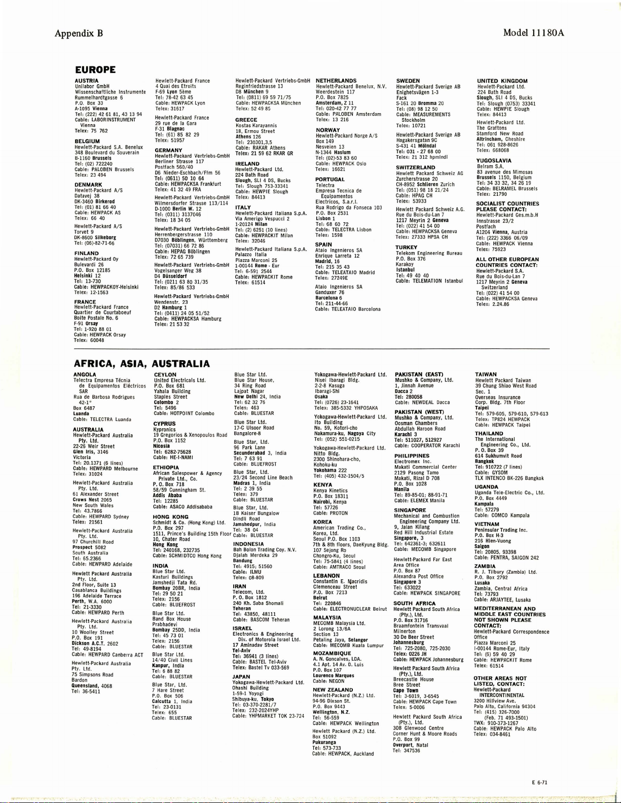
Appendix B
EUROPE
AUSTRIA
Unllabor
GmbH
Wissenschaftliche l nstrumente
Rummelhardtgasse
P
.O. Box
33
A-1095 Vienna
Teh
(222)
Cable,
LABORINSTRUMENT
Vienna
Telex: 75 762
BE
LGIUM
Hewlett-Packard
348
Boule
vard du
8·1160 Brussels
Tel
, (02) 722240
Cable:
PALOBEN
Tele
x:
23
494
DENM
ARK
Hewlett-Packard A/S
Oatavej 38
OK-3460
Birke
Te
h (01)
81
Cable:
HEWPACK
Telex: 66 40
He
wlett-Pac
Torvet 9
DK
-8600 Silkeborg
Ter
,
(0
6)-82-71-66
FINLA
ND
Hewlett-Packard Oy
Bulevardi
P.O.
Box
12185
Helsinki
12
T
er,
13-730
Cable, H
EWPACKOY-He
Telex: 12-1563
FRAN
CE
Hewlett-Packard
Quartier
de
Bolte
Postale
F-91 Orsay
Ter
, 1-920 88
Cable:
HEWPACK
Tel
ex:
60048
6
42
61 81, 43 13 94
S.A.
Souverain
Bruss
rod
66
40
AS
kard
A/ S
26
France
Courtaboeuf
No.
6
01
Orsay
Hewlett-Packard
4
Quai
F-69
T
er,
Cable: HEWPACK Lyon
Telex: 31617
He
wlett.Packard
29
rue
F·31 Blagnac
Te
l,
Tel
Ben
els
lslnkl
ex:
elux
GERMANY
Hewlett·Packard Vertrlebs·GmbH
Be
rliner Strasse
Po
stfach
06
Nieder·Eschbach/
Tel,
Cable: HEWP
Telex: 41
Hewlett·Packard Vertriebs·GmbH
Wflmersdorfer
D-
1000
Tel,
Telex: 18
Hewlett·Packard Vertriebs·
Herrenbergerstrasse
07030 BOb
Tel,
Cable: HEP
Tele
x:
Hewlett·
Vogelsanger
04 Dilsseldorf
Te l, (02 11 63 80
Telex, 85/ 86 533
Hewlett-Packard Vertr
Wendenstr.
02 Ham
Ter
, (0411 ) 24 05
Cable:
Telex:
France
des
Etroits
Lyon
seme
78-42 63 45
Fran
de
(6
1) 85 82
51957
(0611 ) 50 10 64
Berlin
(0311) 3137046
(07031) 66 72 86
72
bur
HEWPACKSA
21
ce
la
Gara
29
117
560/40
Ffm
ACKSA
Frankfurt
32
49
FRA
Strasse
W.
12
34
05
110
lin
gen,
Wi.irttemberg
AG BObllngen
65
739
Packard Vertriebs·GmbH
Weg
38
31
/ 35
23
g 1
51
/ 52
Hamburg
53
32
56
113/114
GmbH
lebs·Gmb
H
Hewlett·Pac
kard
Reginfriedstra
08
Mi.inc
Tel,
Cable:
Telex: 52
GREECE
Kostas
18,
Erm
Ath
ens
Tel,
Cable:
T
ele"
IRELA
Hewlett-Pack
224
S
lou
Tel:
Cable:
Telex: 84413
ITALY
Hewlett-Packard ltaliana S.
Via
Amerigo
1·20124
Ter,
Cable:
Te
lex:
Hew
Palazzo
Piazza
1·
00144 Rom
Teh
Cable: HEWPACKIT
Telex: 61
Vertriebs·GmbH
sse
13
hen 9
(0811) 69 59 71/7
HEWPACKSA Milnchen
49
8!:i
Karayannis
ou
Stree
t
126
230301,3,5
RAKAR
Athens
21
59 62
RKAR
NO
ard
Ltd.
Bath Road
gh,
Sll 4 OS, Bu
gh
753·33341
HEWPIE
Sloug
Vespucci
Milan
6251 (10 lines)
Italia
25
e -
Eur
514
cks
Rome
Slou
(
2)
HEWPACKIT Mila
32046
lett-Packard ltaliana
Marconi
6-591 2544
GR
h
2
5
p.A.
n
S.p.A.
NETHERLANDS
He
wlett.
Packard Bene
Weerdesteln
P
Am
Ter,
Cable: PAL
Telex:
NORWAY
He
Box
Nes
N-1344 Has
Tel, (02)-53 83 60
Cable:
Te
PORTUGAL
Telectra
Empresa
Electricos,
Rua
P
Lisb
Teh
Cable: TELECTRA
Telex:
SPAIN
Ataio l
Enrique Larreta 12
Ma
Tel
Cable:
Telex: 27249
Ataio
Ganduxer 76
Barc
Tel,
Cable
.O.
Box
7825
sterdam, Z
020-42
OBEN
13
216
wlett·
Packard
149
veien
13
HEWPACK Oslo
lex:
16621
Tecni
Equipamentos
Rodrigo
.O.
Box
2531
on
1
68
60 72
1598
ngenieros
drid, 16
, 215 35 43
TELEATAIO
lngenier
elon
a 6
211-44-66
: TELEATAIO
77 77
lum
S.a
E
da
117
11
ca
.r.
os
lux,
Amsterdam
Norge
A/ S
de
I.
Fon
seca
Lisbon
SA
Madrid
SA
Barcelona
SWEDEN
N.V
.
Hewlett-Packard Sverige
Enighetsvligen
Fack
S-
161
Tel
Cable,
Telex:
Hew
Hagake
S·431
Tel
Telex:
SWITZERLAND
Hewlett
Zurcherstrasse
CH-8952
Te
Cable:
Tele
103
Hewlett Packa
Rue
1217 Meyrin
Teh
Cable:
Telex:
TURKEY
Telekom
P.O. Box
Karakoy
Istanbul
Teh
Cable: TELEMATI
1-3
20
Bromma 20
, (08) 98 12 50
MEASUR
EME
Stockholm
10721
lett-Packard Sverige
rsgatan
9C
41 MOlndal
, 031 - 27 68 00
21
312
hpmlndl
Packard
20
Schlieren Zurich
l, (051) 98 18
HPAG
x:
5393
du
Bois·du
(022)
41
HEWPACKSA
27333
Engineeri ng
376
49
40 40
CH
3
54 00
rd
·Lan
2
Gene
HPSA
21
Schweiz
ON
NTS
Schweiz
/24
7
va
Gene
CH
Bureau
Istanbul
UN
AB
Hewlett-Packard
224
Slou
Teh
Cable:
Telex:
He
wle
The
Stamford
AB
Altrinch
Te
l,
Telex:
Y
UGOSLAVIA
Belram
83
AG
Brussels 1150, Bel
Teh
Cable: BEL
Tele
SOCIALIST COUNTRIES
A.G.
PLEASE CONTACT:
Hewlett-Pac
lnnstrasse 23/2
Postfach
va
Al204 V
Te
r, (222) 3366 06/ 09
Cable: HEWPACK
Tel
ex:
AL
L OTHER EUROPEAN
COUNTRIES
Hewlett-Packard
Rue
1217
Switzerland
Teh
Cable: HEWPACKSA
Telex
Model l l 180A
ITED KIN
GDOM
Ltd
Bath
Road
gh,
Sll 4 OS, Buck
Slough
(0753) 33341
HEWPIE
Slough
84413
tt·Packard
Ltd.
Graftons
New
Road
am,
Cheshire
061 928-8626
668068
S.A.
avenue
des
Mimosas
RAME
kard
ien
na, Austria
75923
Bois·dU·Lan
gium
26
L Brussels
Ges.m.b.H
Vienna
CONT
S.A
.
7
va
Gen
34 33 32, 34
x: 21790
du
Meyrin 2 Gene
(022) 4 1 54 00
: 2.24.86
.
19
ACT
s
:
eva
AFRICA,
ANGOLA
Tele
ctra
de
Equipamento
SAR
Rua
de
42·1°
Box
6487
Lua
nda
Cable:
AUSTRALIA
Hewlett-P
Pl
y. Ltd.
22·26 Weir Street
Glen
Iris,
Victoria
Te
l:
20.1371
Cable: HEWPARD Mel
Telex:
31024
He
wlett-Pac
Ply.
Lid
61
Alexander Street
Cro
ws Nest
New
South
Ter
, 43.7866
Cable:
HEWP
Telex: 21561
Hewlett-Packard Australia
Ply. Lid
97
Churchill
Prospect
South
Australia
Te
r, 65.2366
Cable: HEWPARO
Hewlett
Pl
y.
Ltd
2n
d Floor, Suite
Casablanca
196
Adelaide
Perth,
W.A.
T
er,
21-3330
Cable:
HEWPARO
Hewlett-P
Ply.
ltd.
10
Woolley Street
P.O.
Box
Dicks
on
Tel:
49-8194
Cable: HEWPARD
He
wlett-Packard Australia
Pt
y.
ltd.
75
Simpsons
Bardon
Queens
land, 4068
Tel: 36·5411
ASIA, AUSTRALIA
Empre
sa
T~cnia
s
El~ctr
Barb
osa
Rodrigu
TELECTRA
Luand
ackard
Austral
3146
(6
lines)
bourne
kard
Australia
.
2065
Wales
ARD
Sydney
.
Road
5082
Adelaide
Packard
Australia
.
13
Buildlngs
Terrace
6000
Perth
ackard
Australia
191
A.C.
T.
2602
Canberra
Road
icos
es
a
ia
ACT
CEYLON
United Electricals
P.O. Box
681
Yahala
Building
Staples Street
Colombo
2
Teh 5496
Cable:
HOTPOINT
CYPRUS
Kypronlcs
19
Gregorios &
P.O. Box
Nico
Teh 6282-75628
Cable, HE
ETHIOPIA
African
Private Ltd.,
P.
C. B
58/59
Add
Tel,
Cable: ASACO
HONG
~~~~~~~
1511
1
0,
Hong Kon
Teh 240168, 232735
Cable:
I
NOIA
Blue
Kasturi Buildings
Jamshedji
Bomb
Ter,
Telex: 2156
Cable,
Blue
Band
Prabhade11i
Bomb
Tel
, 45 73
Te
lex:
Cable:
Blue
14/40
Kanpur, I
Te
l: 6
Cable
Bl
ue
7
Hare
P
.O.
Calcutta 1,
Tel:
T
elex: 655
Cable:
Xenopoulos
1152
sia
-1-NAMI
Salespowe
Co.
ox
718
Cunningham
is
Ababa
12285
Addisababa
KONG
&2~r
<Hong
, Prince's Building 15th
Chaler Road
g
SCHMIOTCO
Star Ltd.
Tata
Rd.
ay
20BR,
India
29
50 21
BlUEFROST
Star Ltd.
Box
House
ay
2500, India
01
2156
BLUESTAR
Star Ltd.
Civil
Line
s
ndia
88
82
: BLUE
STAR
Star,
Ltd.
Street
Box 506
Ind
ia
23·0131
BLUESTAR
ltd
.
Colombo
r &
Agency
St.
Kong) lid
Hong
Blue
Blue
34
Lajpat
New
Te
l, 62 32 76
Telex:
Cable:
Bl
ue
17·C
Bangalore-a
Road
Blue
96
Secund
Tel:
Cable,
Blue
23/24
Madr
Tel,
Telex:
Cable: BLUESTAR
Blue
lB
Kaiser
Dindfi R
.
~!rs~~
Floor
Cable:
I
NDONESIA
B
ah Bolon
DJalah
Kong
Ba
ndun
Teh
Cable,
Telex: 08-809
IRAN
Telecom,
P.
o.
240 Kh.
Teher
Tel,
Cable:
IS
RAEL
Electronics & Engineering
Div.
17
Amlnadav
Tel-Aviv
Teh 36941
Cable:
Telex:
JAPAN
Yokogawa-Hewlett·Packard
Ohas
1·59-1
Shibuya-ku, Tok
Te
l,
Telex:
Cable:
Star Ltd.
Star
Hou
se,
Ring
Road
Nagar
Deihl 24
, India
463
BLUESTAR
Star
ltd.
Ulsoor Road
Star,
Ltd
.
Park Lane
era
bad
3,
7
as
2 39 55
4915; 51560
43850, 48111
hi Building
03-370-2281/ 7
India
63
91
BlUEFROST
Star,
ltd.
Second line
Bea
1, I
ndia
379
Star,
lid
.
Bungalow
oad
d
~~r
,
India
BLUESTAR
Trading
Coy
Merdeka
29
g
ILMU
ltd
.
Box 1812
Saba
Shomali
an
BASCOM Teheran
of Motorola Israel Ltd.
Street
(3
li
nes)
BASTEL
Tel-A
Tv
033·569
yo
232-2024YHP
YHPMARKET
viv
TOK
Baster
Yoyogi
ch
. N
23·724
.V.
Ltd.
Yokogawa·
Hewlett-Pac kard ltd.
Ni
sei
tbaragi
2
lbaragi·Shi
O
Te
Telex: 385·5332
Yokogawa·
Ito Building
No.
Na
Te
Yokogawa-
Nitto
2300
Kohoku-ku
Yokohama
Te
KENY
Kenya Kinetics
P.
Nairob
Tel
Cable:
KOREA
American Trading
Korea
Seoul
7th & 8th floor
107
Chongro-Ku,
Tel:
Cable: AMT
LEBANON
Consta
Cl
P.
Beirut
Tel
Cable: ELE
MALAY
MECOMB
2 Lorong 13/
Section
Petaling
Cable: MECOMB
MOZAMBIQUE
A.
4.1
P
.O.
Lourenco
Cable: NEGON
N
Hewlett94·96
P
.O.
Wellington, N.Z.
Tel
Cable: HEWPACK
Hewlett
B
ox
Pukuranga
Teh 573-733
Cable:
Bldg
-2·8 Kasuga
saka
l, (0726) 23-1641
Hewlett·Packard
59,
Kotorl-cho
kamura-ku, Nagoya City
r, (052) 551-0215
Hewlett-Packard
Bldg
.
Shinohara-cho
222
h (405) 432-1504/ 5
A
O.
Box 18311
i,
Kenya
, 57726
PROTON
, Ltd.
P.O.
Box
1103
s,
Sejong
Ro
Seoul
75·5841
(4
lines)
RACO
ntin E. t4acridls
emenceau
Street
O.
Box
7213
,
22
0846
CTRONUCLEAR
SIA
Malaysia
6A
13
Jaya,
Sel
N.
Goncalves, LOA
Apt.
14
Av.
D. Luis
Box
107
Marque
s
EW ZEALA
ND
Packard (N.Z.) ltd.
Dixson
St.
Box
9443
, 56-559
Packard (N.Z.) ltd.
510
92
HEWPACK, Auckland
.
YHPOSAKA
lid.
,
Co.,
OaeKyung Bld
Seoul
Beirut
ltd.
ang
or
Kuala Lumpur
.
Wellington
PAKISTAN
Mu
shko & Company,
1,
Jinnah
D
acca
Teh 280058
Cable:
PAK
ISTAN (WEST)
Ltd
.
Mushko & Company, Ltd
Cosman
Abdullah
K
arachi 3
Tel, 511027, 512927
Cable:
PHILIPPINES
Electromex Inc.
Makatl
2129
Pasong Tamo
Makati,
P.O.
Box
Manila
Teh
89-85-01; 88-91-71
Cable:
SINGAPORE
Mechanical
Engineering
9, Jalan
Red Hill
Singapo
Tel,
642361-3; 632611
g.
Cable:
Hewlett·Packard
Area
Offi
P.O.
Box
Alexandra
Singapo
Teh
633022
Cab
le, HEWPACK
SOUTH AFRICA
Hewlett Packard
(
Pty.
P.O. B
ox
Braamfo
Milnerton
30
De
Beer
Jo
hannesbu
Tel,
725-2080, 725-2030
Tel
ex,
Cable:
Hewlett Packard
(Pty.),
Breecastte
Bree
Street
Ca
pe Town
Tel,
3-6019, 3-6545
Cable:
Telex:
Hewlett
(
Ply.),
30B
Glenwood
Corner Hunt &
P.O.
Box
Overport, Natal
Tel:
347536
(EASn
Avenue
2
NEWDEAL Da
cca
Chambers
Haroon
Road
COOPERATOR
ELEMEX Manila
re, 3
MECOMB Singapore
re
Commercial
Rizal D 708
1028
and
Combustion
Company
Kilang
Industrial Estate
Far East
ce
87
Post
Offi
ce
3
Karachi
Center
SINGAPORE
South
), ltd.
31716
ntein T
ransvaal
Street
rg
0226 JH
HEWPACK Joha
HEWPACK
5·0006
ltd .
House
Packard
Ltd.
99
South
Cape
South Afr
Centre
Moore
nnesburg
Roads
ltd
Town
TAIWAN
.
Hewlett
39 Chung
Sec.
Overseas
Corp. Bldg
Taip
Teh
.
Telex:
Cable: HEWPACK
THAILAND
The
P.
614 Sukh
Bangkok
Teh
Cable:
TLX INTE
UGANDA
Uganda
P.O.
Kampala
Tel, 57279
Cable:
ltd.
VIETNA
Pe
P.O.
216
Salc
Tel,
Cab
ZAMBIA
R. J. Tilbury (
P
.O.
L
usaka
Zambia,
Ter,
Cable:
MED
Africa
MIDDLE EAST COUNTRIES
NOT SHOWN
CONTA
Hew
Office
Piazza
1·00144
Tel
Cable: HEWPACKIT
Telex: 61514
Africa
OTHER AREAS NOT
LI
STED, CONTACT:
Hewlett-Packard
INTE
3200
Palo
Teh
ica
Twx
Cable: HEWPA
Telex
Packard
Taiwan
Shiao
West
Insurance
. 7th Floor
39
umvlt
(7
lines)
NCO
BK-
4449
H-3
NTRA,
Zambia) Ltd
2792
Ave.
CK
Taipei
al
Road
226
Kampala
SAIGON
PLEA
25
Italy
Rome
L
94304
Palo
Road
Bangkok
.,
Ltd
242
.
NO
SE
Alto
1
ei
579-605, 579-610, 579-613
TP824 HEWPACK
Internation
Engineering Co., Ltd.
o. B
ox
910722
GYSOM
Tete-Electric Co
Box
COMCO
M
ninsular Trading Inc.
Box
Hien-Vuong
on
20805, 93398
le, PE
Box
Central Africa
73793
ARJAYTEE, Lusaka
ITERRANEAN A
CT:
lett-Packard Correspondence
Marconi
Rome-Eur,
,
(6)
59 40 29
RCONTINENTA
Hillview
Alto, California
(4
15) 326-7000
(Fe
b. 71 493-1501)
, 910-373- 1267
: 034·8461
.
E 6-71
-1
Page 58

 Loading...