

Page 1
HP 10Gb Ethernet
BL-c Switch
Installation Instructions
Overview
This card contains information on how to set up the contents
of the kit for your use.
For more information on switch installation and to download
management utilities and firmware, see the HP website
(http://www.hp.com/go/bl
adesystem/documentation
).
Kit contents
•
One HP 10Gb Ethernet BL-c Switch
•
This installation card
•
Limited warranty and material limitations documentation
Preparing for installation
IMPORTANT:
record of the MAC address (printed on the MAC
address label attached to the switch). This address is
needed when configuring the switch.
Before installing the switch, make a
© Copyright 2007 Hewlett-Packard Development Company, L.P.
The information contained herein is subject to chan
only warranties for HP products and services are set fo
warranty statements accompanying su
herein should be construed as constituting an additional warranty. H
not be liable for technical or editorial errors or omissions co
Part Number 445943-001
March 2007 (First Edition)
ch products and services. Nothing
ge without notice. The
rth in the express
ntained herein.
P shall
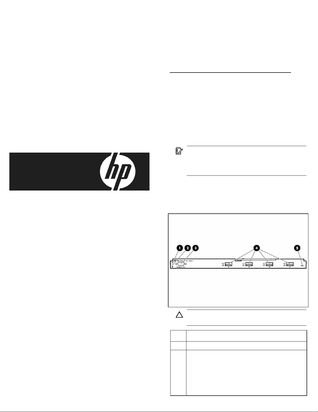
10Gb Ethernet BL-c Switch front
panel
CAUTION:
Health LED is green resets the switch.
Item Description
1 UID LED
2 Health LED
• Off—Not powered up
• Green—Powered up and all ports match
•
Pressing the Reset button while the
Amber—Indicates a problem such as a port
mismatch. For more information, see the HP
BladeSystem enclosure quick setup instructions.
Page 2
Item Description
3 DB-9 management serial port
4 XFP transceiver cage ports 18 - 21
• Green—Link LED (top)
• Flashing green—Activity LED (bottom)
5 Reset button
Planning the switch
configuration
The switch ships with a default configuration in which all
downlink and uplink ports are enabled and assigned a
default VLAN with a VID equal to 1. This default configuration
simplifies the initial setup by a
cable (from any external Ethernet connector) to connect the
server blade enclosure to the network. Assess the switch
configuration requirements befo
your network environment.
llowing use of a single uplink
re connecting the switch to
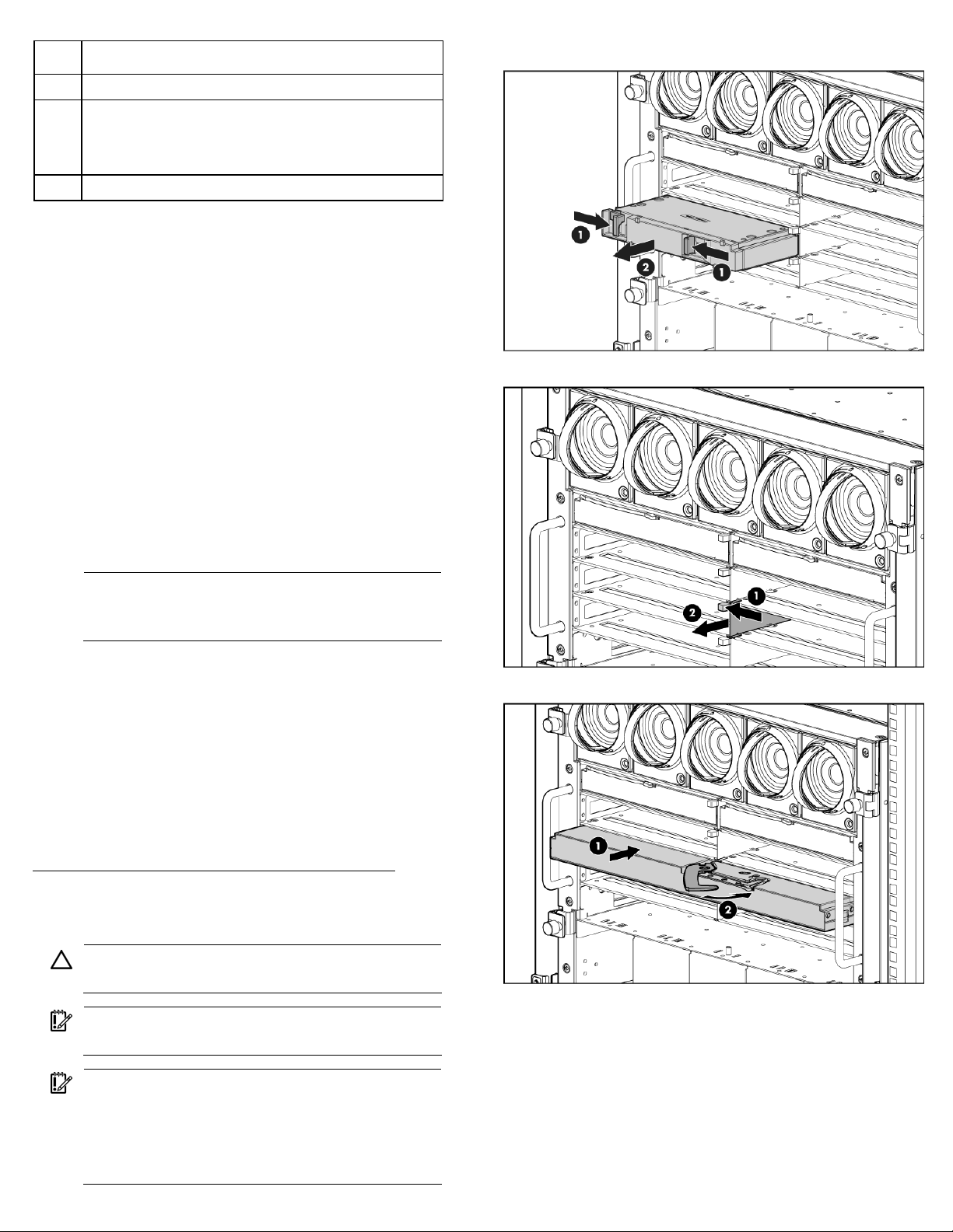
1.
Remove the air baffles.
2.
Remove the divider.
The switch does not affect or
determine NIC numeration and
the associated mapping of NIC interfaces to switch ports. The
numbering of the NICs on the server (for example, NIC 1,
NIC 2, NIC 3) is determined by
operating system, and which NICs are enabled on the server.
NOTE:
Port 17 is reserved for connection to the
the server type, the server
Onboard Administrator module for switch
management.
The Onboard Administrator modu
le controls downlink port
enabling. Enabling is based on matching ports between the
server and the interconnect
Onboard Administrator module ve
bay. Before power up, the
rifies that the server NIC
option matches the switch bay that is selected and enables all
ports for the NICs installed.
For detailed port mapping information, see the HP
BladeSystem enclosure quick setup instructions or the HP
BladeSystem enclosure setup and installation guide on the HP
website
(http://www.hp.com/go/bl
adesystem/documentation
).
Installing the switch
CAUTION:
configuration.
IMPORTANT:
configuration matches the switch bay selected.
IMPORTANT:
Enclosure, the switch can only be installed in bays
5/6 or 7/8.
Do not cable the switch until after
Make sure that the server NIC
For the HP BladeSystem c7000
3.
Install the switch.
A successful installation is indicated by a green Health LED. If
the Health LED is amber or powe
r is not applied to the switch,
see the "Troubleshooting" section of the HP BladeSystem
enclosure setup and installation guide for more information.
For a cabling diagram, see the HP BladeSystem enclosure
setup and installation guide.
For the HP BladeSystem c3000 Enclosure, the switch
can only be installed in bays 3/4.
Page 3

Accessing the switch
The switch is accessed remotely using the Ethernet ports or
locally using the DB-9 management serial port.
To access the switch remotely:
1.
Assign an IP address. By defaul
t, the switch is set up to
obtain its IP address from a BOOTP server existing on
the attached network.
2.
From the BOOTP server, use the switch MAC address to
obtain the switch IP address.
3.
From a computer connected to
IP address to access the swit
telnet application, which en
BBI or CLI. The switch logon prompt appears.
NOTE:
If the switch does not obtain the IP address
the same network, use the
ch using a Web browser or
ables access to the switch
by means of the BOOTP service, access the switch
locally and configure the IP address manually. After
assigning the IP address to the switch, then access
the switch remotely.
To access the switch locally:
1.
Connect the switch DB-9 seri
modem serial cable to a loca
al connector, using a null-
l client device (such as a
laptop computer) with VT100 terminal emulation
software.
2.
Open a VT100 terminal emulation session with these
settings: 9600 baud rate, eight data bits, no parity, one
stop bit, and no flow control.
Logging on and configuring
the switch
To log on to the switch:
1.
Access the switch ("Accessing the switch" on page 2).
After connecting to the switch console, the login prompt
appears.
2.
Enter admin as the default administrator password.
The Main Menu appears and displays all administrator
privileges:
See the
Guide
configuration settings, and moni
HP 10Gb Ethernet BL-c Switch Command Reference
for information on configur
ing the IP address, changing
toring switch operation using
one of the following interfaces:
•
Local RS-232 serial console management interface
•
Remote telnet console management interface
See the
Interface Reference Guide
HP 10Gb Ethernet BL-c Switch Browser-based
for information on using the
embedded HTML interface to manage the switch from
anywhere on the network using a standard browser, such as
Netscape Navigator or Microsoft
®
Internet Explorer.
See "SNMP MIBs support" for more information on the SNMP
agents. This section also desc
ribes how to use the MIBs to
configure and monitor the switch using a generic SNMP
manager, such as HP OpenVi
HP Systems Insight Manager.
ew Network Node Manager or
Installing XFP transceivers
CAUTION:
cable or the XFP transceiver, do not install or remove
fiber-optic XFP transceivers
Disconnect all cables from
removing or installing an XFP transceiver.
CAUTION:
transceiver can shorten the useful life. Do not remove
and insert XFP transceive
necessary.
CAUTION:
preventative wrist strap to
metal surface on the chassi
discharge.
CAUTION:
fiber-optic XFP transceiver or the rubber caps from
the fiber-optic cable until you are ready to connect
the cable. The plugs and caps protect the XFP
1.
transceiver ports and cables from contamination and
ambient light.
Remove the dust plug and save for future use.
IMPORTANT:
from HP.
To prevent damage to the fiber optic
with cables attached.
the XFP transceiver before
Removing and installing an XFP
rs more often than is
HP recommends attaching an ESD-
your wrist and to a bare
s to prevent electrostatic
Do not remove the dust plugs from the
Use only XFP transceivers purchased
Page 4
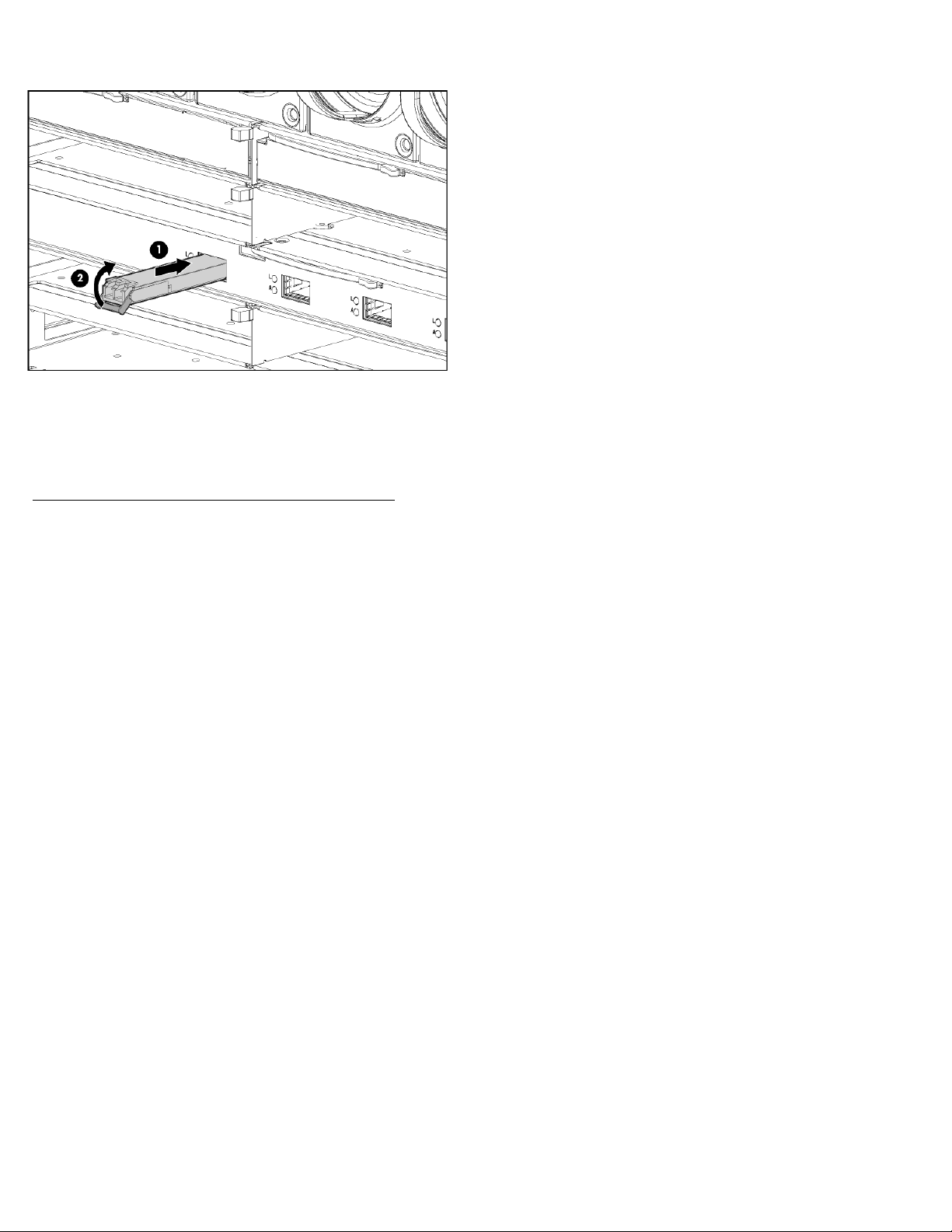
2.
Insert the XFP transceiver. With
latch closed, be sure that
the transceiver is fully seated and securely in place.
Regulatory notice
For complete details, see the
User Guide
located on the HP website
(http://www.hp.com/go/bl
HP 10Gb Ethernet BL-c Switch
adesystem/documentation
).
 Loading...