

Page 1

Agilent MOI for 10GBASE-KR/40GBASE-KR4 Interconnect Tests
Revision 1.00
Apr-21, 2014
10GBASE-KR/40GBASE-KR4
Agilent Method of Implementation (MOI) for
10GBASE-KR/40GBASE-KR4 Backplane Ethernet
Interconnect Using Agilent E5071C ENA Option TDR
1
Page 2

Agilent MOI for 10GBASE-KR/40GBASE-KR4 Interconnect Tests
Table of Contents
1. Revision History ............................................................................................................. 4
2. Purpose ........................................................................................................................... 4
3. References ...................................................................................................................... 4
4. Required Equipment ....................................................................................................... 4
5. Test Procedure ................................................................................................................ 5
5.1. Outline of Test Procedure ......................................................................................... 5
5.2. Instrument Setup ....................................................................................................... 7
5.2.1. Recalling a State File ......................................................................................... 7
5.2.2. Saving a State File ............................................................................................. 8
5.2.3. Loading a VBA Project File .............................................................................. 9
5.3. Calibration .............................................................................................................. 10
5.3.1. Time & Frequency Domain Calibration (Channel 1) ...................................... 10
5.3.2. Frequency Domain Calibration (Channel 2) ................................................... 12
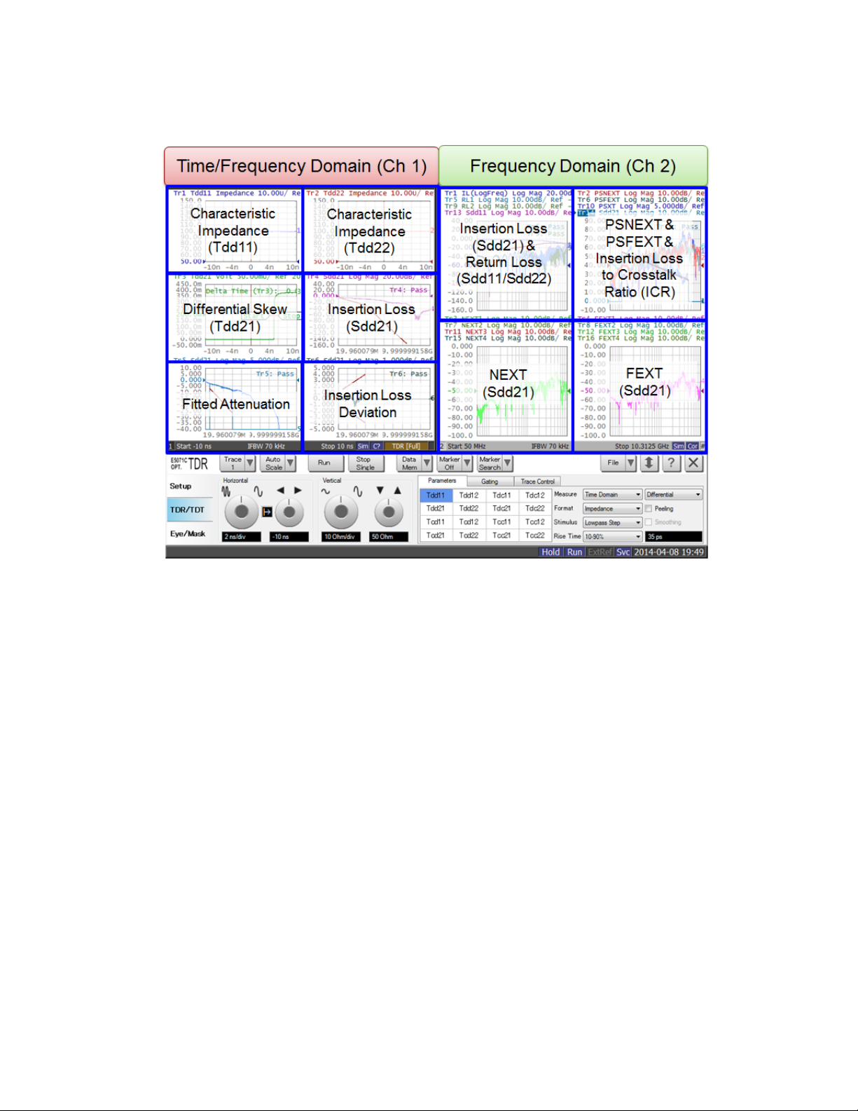
5.4. Measurement .......................................................................................................... 14
5.4.1. Characteristic Impedance ................................................................................ 14
5.4.2. Differential Skew ............................................................................................. 15
5.4.3. Insertion Loss .................................................................................................. 15
5.4.4. Fitted Attenuation ............................................................................................ 16
5.4.5. Insertion Loss Deviation .................................................................................. 17
5.4.6. Return Loss ...................................................................................................... 17
5.4.7. Power Sum Differential Near-end Crosstalk (PSNEXT) ................................ 18
5.4.8. Power Sum Differential Far-end Crosstalk (PSFEXT) ................................... 19
5.4.9. Power Sum Differential Crosstalk (PSXT) ..................................................... 21
5.4.10. Insertion Loss to Crosstalk Ratio (ICR) .......................................................... 21
6. [Appendix] Manual Setup ............................................................................................ 22
6.1. Channel & Trace Setup (Channel 1) ....................................................................... 22
6.2. Characteristic Impedance ....................................................................................... 23
2
Page 3

Agilent MOI for 10GBASE-KR/40GBASE-KR4 Interconnect Tests
6.3. Differential Skew .................................................................................................... 24
6.4. Insertion Loss (Liner Frequency Sweep) ............................................................... 25
6.5. Fitted Attenuation ................................................................................................... 25
6.6. Insertion Loss Deviation ......................................................................................... 25
6.7. Common Parameters Setup for Frequency-domain Measurements (Channel 2) ... 26
6.8. Insertion Loss (Log Frequency Sweep) .................................................................. 26
6.9. Return Loss ............................................................................................................. 27
6.10. Power Sum Differential Near-end Crosstalk (PSNEXT) ....................................... 27
6.11. Power Sum Differential Far-end Crosstalk (PSFEXT) .......................................... 28
6.12. Power Sum Differential Crosstalk (PSXT) ............................................................ 29
6.13. Insertion Loss to Crosstalk Ratio (ICR) ................................................................. 29
6.14. Defining Limit Line Tables .................................................................................... 29
3
Page 4

Agilent MOI for 10GBASE-KR/40GBASE-KR4 Interconnect Tests
Revision
Comments
Issue Date
1.00
Initial Revision.
Apr-21, 2014
1. Revision History
2. Purpose
This test procedure was written to explain how to use the Agilent ENA Option TDR to
make the 10GBASE-KR/40GBASE-KR4 Backplane Ethernet interconnect measurements.
3. References
IEEE 802.3-2012 Section 5 (Jun. 2013)
4. Required Equipment
1. E5071C ENA Series Network Analyzer
Option 4K5 (20 GHz)
Option TDR (Enhanced time domain analysis)
2. Test Fixture
n/a
3. 4-port ECal Module
N4433A (for E5071C-4K5)
4. Coaxial RF cables
5. 50 Ohm terminators (if required)
4
Page 5

Agilent MOI for 10GBASE-KR/40GBASE-KR4 Interconnect Tests
5. Test Procedure
5.1. Outline of Test Procedure
1. Instrument Setup
Automatic setup by recalling a state file or manual setup.
Post processing (calculation) by loading a VBA project file using user menu
function.
2. Calibration
ECal Calibration
3. Measurements
4-1. Time-domain Measurements
- Characteristic Impedance
- Differential Skew
4-2. Frequency-domain Measurements
- Fitted Attenuation
- Insertion Loss
- Insertion Loss Deviation
- Return Loss
- Power Sum Differential Near-end Crosstalk (PSNEXT)
- Power Sum Differential Far-end Crosstalk (PSFEXT)
- Power Sum Differential Crosstalk (PSXT)
- Insertion Loss to Crosstalk Ratio (ICR)
5
Page 6
Agilent MOI for 10GBASE-KR/40GBASE-KR4 Interconnect Tests
Note: Hard Keys (Keys on the E5071C’s front panel) are displayed in Blue color and Bold.
(Example: Avg, Analysis)
Note: Soft keys (Keys on the E5071C’s screen) are displayed in Bold. (Example: S11, Real,
Transform)
Note: Buttons of the TDR software are displayed in Green color and Bold. (Example: Trace,
Rise Time)
Note: Tabs of the TDR software are displayed in Brown color and Bold. (Example: Setup,
Trace Control)
6
Page 7
Agilent MOI for 10GBASE-KR/40GBASE-KR4 Interconnect Tests
5.2. Instrument Setup
5.2.1. Recalling a State File
This section describes how to recall a state file of the E5071C that includes all the
measurement settings for 10GBASE-KR/40GBASE-KR4 backplane Ethernet interconnect
tests. The state file can be downloaded at: www.agilent.com/find/ena-tdr_ethernet-cabcon
Copy the state file into the E5071C’s directory via USB mass storage device and recall the
state file using the TDR software. Necessary parameters for testing are automatically set up
in the E5071C. Refer to Appendix for the details about manual setup.
If TDR setup wizard is shown, click Close button in the TDR setup wizard main window.
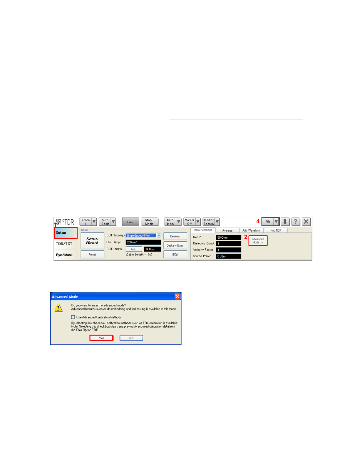
1. Open Setup tab.
2. Click Advanced Mode to show the dialog box.
3. A dialog box appears requesting for confirmation. Then click Yes. (Uncheck “Use
Advanced Calibration Methods”)
4. Click File and select Recall State to open the Recall State dialog box.
5. Specify a folder and a file name, and click Open.
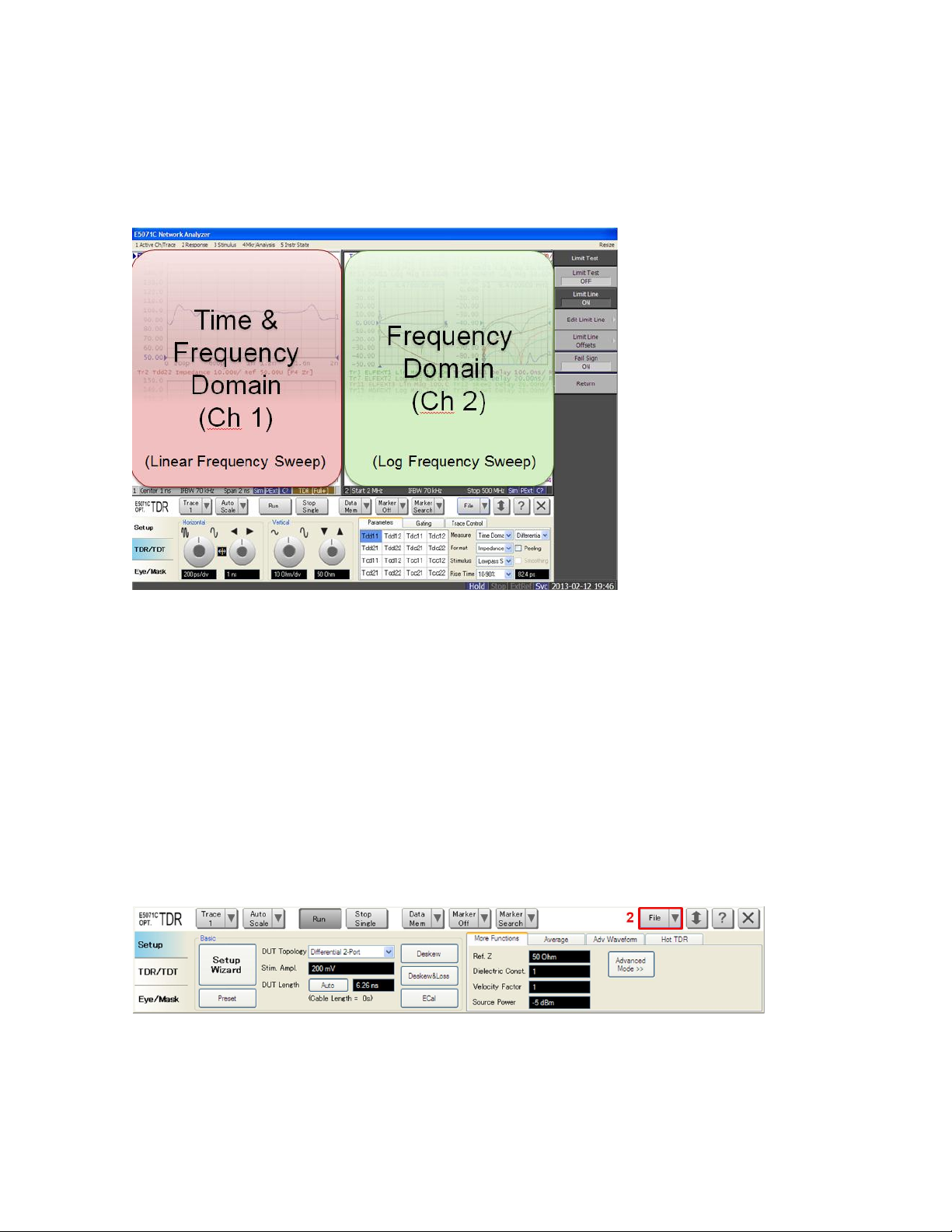
The E5071C’s channel 1 is used for both time & frequency domain measurements with
linear frequency sweep by using the TDR software at the bottom of the E5071C’s screen.
7
Page 8
Agilent MOI for 10GBASE-KR/40GBASE-KR4 Interconnect Tests
The channel 2 is used for frequency-domain measurements with log frequency sweep by
using the soft key on the right side of the screen or hard key on the front panel.
5.2.2. Saving a State File
All the measurement settings including calibration information can be saved in a state file
(*.tdr). After performing calibration, all necessary calibration coefficients are saved in a
state file and can be recalled for the next measurements.
1. Press Save/Recall > Save Type and select State & Cal as a state file type.
2. Click File of the TDR software.
3. Select “Save State”.
4. Enter file name and save the state file with calibration information
8
Page 9
Agilent MOI for 10GBASE-KR/40GBASE-KR4 Interconnect Tests
1
3
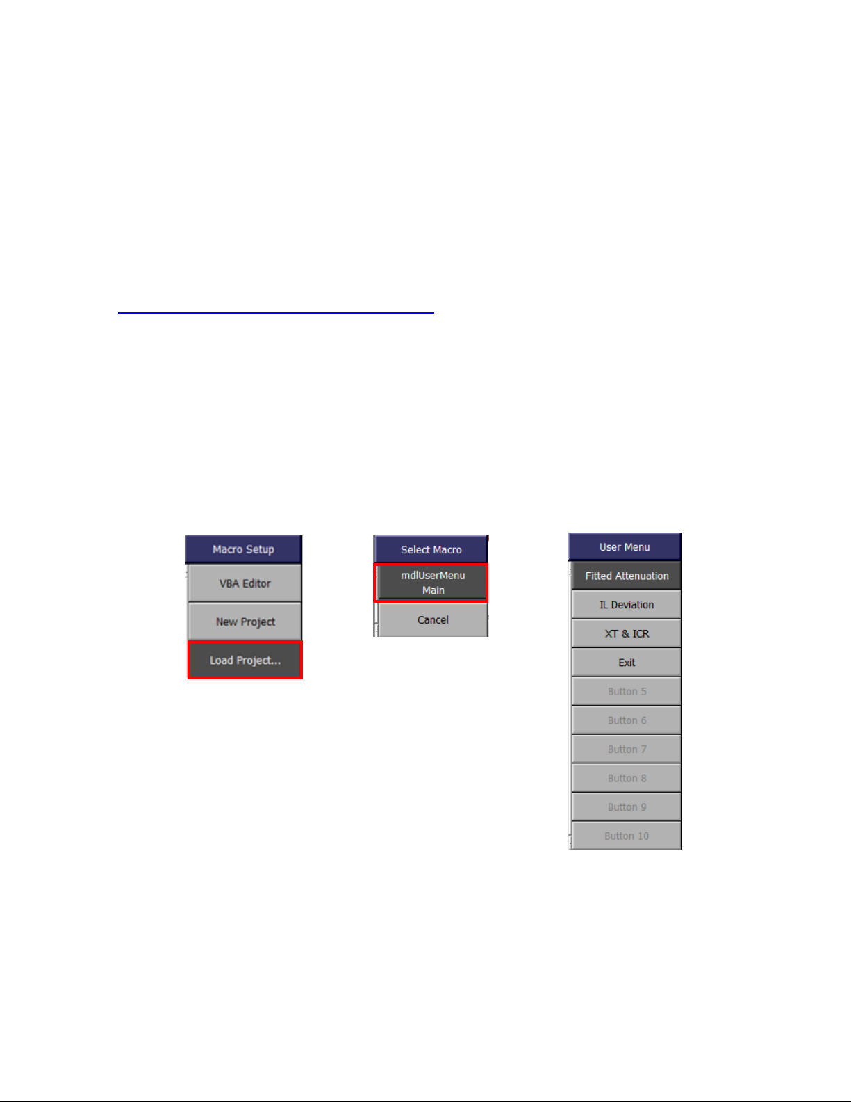
5.2.3. Loading a VBA Project File
The user menu function, which lets the users perform procedures assigned to specific soft
keys, is useful to perform the post processing. This section describes how to load a VBA
project file of the E5071C that perform the calculation for 10GBASE-KR/40GBASE-KR4
backplane Ethernet interconnect tests. The VBA project file can be downloaded at:
www.agilent.com/find/ena-tdr_ethernet-cabcon
Copy the VBA project file into the E5071C’s directory via USB mass storage device and
recall the VBA project file.
1. Press Macro Setup > Load Project… to open the dialog box.
2. Specify a folder and a file name, and click Open.
3. Press Macro Setup > Select Macro > mdlUserMenu Main to load the VBA project.
9
Page 10

Agilent MOI for 10GBASE-KR/40GBASE-KR4 Interconnect Tests
5.3. Calibration
5.3.1. Time & Frequency Domain Calibration (Channel 1)
The purpose of this step is to calibrate the delay and loss of the RF cables and test fixtures
by following the wizard of the E5071C TDR software. Full calibration is performed by
using the 4-port ECal Module at the end of RF cables connected to the E5071C’s test ports.
After connecting the test fixture to the cables, the effect of the fixture can be removed by
the fixture compensation function of the TDR software if required. This calibration is
applied for time & frequency domain measurements in Channel 1.
5.3.1.1. ECal Calibration & Fixture Compensation
Calibration for time & frequency domain measurements is performed by the TDR software.
The 4-port ECal Module (i.e. N4433A) connected to the USB port of the E5071C is
necessary for the calibration procedure.
1. Press Channel Next to select Channel 1.
2. Open Setup tab of the TDR software.
3. Click ECal to launch calibration wizard.
4. Connect all test cables to the ECal Module and click Calibrate. Once green check
mark appears, click Next>.
10
Page 11

Agilent MOI for 10GBASE-KR/40GBASE-KR4 Interconnect Tests
5. If it is not required to perform the fixture compensation, click Finish. If required to
compensate the fixture effects, disconnect the ECal Module and connect the test
fixtures to the RF cables. Click Fixture Comp to perform fixture compensation. Once
green check mark appears, click Finish to complete the compensation.
6. Connect DUT to the test fixtures.
7. Open Setup tab.
8. Click Auto to launch the diagram.
11
Page 12

Agilent MOI for 10GBASE-KR/40GBASE-KR4 Interconnect Tests
9. Click Measure to specify DUT’s electrical length in the dialog box. Once green check
mark appears, click Finish.
5.3.2. Frequency Domain Calibration (Channel 2)
The purpose of this step is to calibrate out the RF effects (i.e. mismatch, loss or delay) of
RF cables and test fixtures. Full calibration is performed by using the 4-port ECal Module
at the end of RF cables connected to the E5071C’s test ports. And if required, the test
fixtures are connected to the RF test cables, and the fixture’s effect will be eliminated by
auto port extension function of the E5071C’s firmware. The calibration is applied for
frequency-domain measurements in Channel 2.
12
Page 13

Agilent MOI for 10GBASE-KR/40GBASE-KR4 Interconnect Tests
5.3.2.1. ECal Calibration
Calibration for the frequency-domain measurement is performed by selecting the E5071C’s
soft key. The 4-port ECal Module (i.e. N4433A) connected to the USB port of the E5071C
is necessary for the calibration procedure.
1. Press Channel Next key to select Channel 2.
2. Connect all RF test cables to the ECal Module.
3. Press Calibrate > ECal > 4-Port Cal.
5.3.2.2. Auto Port Extension
If required, the effect of the test fixtures (i.e. delay) can be removed by auto port extension
function of the E5071C’s firmware. The calibration plane (at the RF test cables by ECal
calibration) is moved to the end of test fixtures by auto port extension.
1. Connect the test fixture to the RF cable. The DUT is not connected to the test fixture
(the fixture end is left open).
2. Press Cal > Port Extension > Auto Port Extension > Select Ports and check all ports
(Port 1 to Port 4).
3. Press Cal > Port Extension > Auto Port Extension > Measure Open and select All
to enable auto port extension.
13
Page 14

Agilent MOI for 10GBASE-KR/40GBASE-KR4 Interconnect Tests
E5071C
Port 1
Port 2
Port 3
Port 4
Test Point
TP1 +
TP1 -
TP4 +
TP4 -
TP1
TP4
Mated Connector
5.4. Measurement
The procedures for time-domain and frequency-domain measurements are introduced in
this section. The physical connections depend on the manufacture’s backplane
configuration and the number of measurements depends on the number of lanes.
5.4.1. Characteristic Impedance
1. Connect the E5071C and the test fixture with the RF cables (Figure 5-1).
Figure 5-1 Characteristic Impedance Test Setup
Note: Unused fixture ports should be terminated with 50 ohm terminators if required.
2. Press Channel Next to select Channel 1 of the E5071C.
3. Select Trace 1 (Tdd11).
4. Click Stop Single.
5. Confirm the differential characteristic impedance is 100 ohm ± 10 ohm.
6. Select Trace 2 (Tdd22)
7. Confirm the differential characteristic impedance is 100 ohm ± 10 ohm.
14
Page 15

Agilent MOI for 10GBASE-KR/40GBASE-KR4 Interconnect Tests
E5071C
Port 1
Port 2
Port 3
Port 4
Test Point
TP1 +
TP1 -
TP4 +
TP4 -
5.4.2. Differential Skew
The skew (propagation delay) between duplex channel pair combinations of a interconnect
should meet requirement.
1. Connect DUT to the test fixtures with the RF cables (Figure 5-1).
2. Select Trace 3 (Tdd21).
3. Click Stop Single.
4. Click Data Mem > Data -> Mem to copy the trace data to memory.
5. Click Data Mem > Data & Memory to show the data & memory traces.
6. Change DUT connection to another duplex channel pair.
7. Click Stop Single.
8. Click Auto Scale and select “Y”.
9. Read Delta Time (Tr3).
10. Confirm the total differential skew from TP1 to TP4 is less than the minimum transition
time for port type of interest.
5.4.3. Insertion Loss
1. Connect DUT to the test fixtures with the RF cables (Figure 5-1).
2. Select Trace 4 (Sdd21).
3. Click Stop Single.
4. Confirm the measured differential insertion loss meets the limit shown below.
15
Page 16

Agilent MOI for 10GBASE-KR/40GBASE-KR4 Interconnect Tests
5. Press Channel Next to select Channel 2 of the E5071C.
6. Press Trace Next to select Trace 1 (Sdd21).
7. Press Trigger > Single.
8. Press Display > Data -> Mem to copy the trace data to memory.
9. Press Display > Display then select Mem to show the memory trace. The measured
differential insertion loss with log frequency sweep will be used for calculation of
insertion loss to cross-talk ratio (ICR) in 5.4.10.
5.4.4. Fitted Attenuation
The fitted attenuation is defined to be the least mean squares line fit to the insertion loss
computed over the frequency range 1 GHz to 6 GHz. The maximum fitted attenuation due
to trace skin effect and dielectric properties is defined.
1. Press Channel Next to select Channel 1 of the E5071C.
2. Select Trace 5.
3. Press Macro Setup > User Menu to show the programs.
4. Press Fitted Attenuation to perform the least mean squares line fit to the insertion loss
measured in 5.4.3. The fitted attenuation result is stored in the data trace while the
insertion loss result (Channel 1/Trace 4) in 5.4.3 is stored in the memory trace.
5. Confirm the calculated fitted attenuation meets the limit shown below.
16
Page 17

Agilent MOI for 10GBASE-KR/40GBASE-KR4 Interconnect Tests
5.4.5. Insertion Loss Deviation
Insertion loss deviation is the difference between the insertion loss and the fitted
attenuation.
1. Select Trace 6.
2. Press Macro Setup > User Menu to show the programs.
3. Press IL Deviation to calculate the difference between the insertion loss in 5.4.3 and
the fitted attenuation in 5.4.4.
4. Confirm the calculated insertion loss deviation meets the limit shown below.
5.4.6. Return Loss
1. Connect the E5071C and the test fixtures with the RF cables (Figure 5-1).
2. Press Channel Next to select Channel 2 of the E5071C.
3. Press Trace Next to select Trace 5 (Sdd11).
4. Press Trigger > Single.
5. Confirm the measured return loss meets the limit shown below.
17
Page 18

Agilent MOI for 10GBASE-KR/40GBASE-KR4 Interconnect Tests
5. Press Trace Next to select Trace 9 (Sdd22).
6. Confirm the measured return loss meets the limit of Step 5.
5.4.7. Power Sum Differential Near-end Crosstalk (PSNEXT)
The differential near-end crosstalk at TP4 is calculated as the power sum of the individual
NEXT aggressors (PSNEXT). PSNEXT is computed as equation, where NEXTn is the
crosstalk loss (dB) of aggressor n. For the case of a single aggressor, PSNEXT will be the
crosstalk loss for that single aggressor.
The following procedure guides how to make measurements of the NEXT of a duplex
channel followed by a different NEXT. Up to 4 NEXT measurements can be made for the
PSNEXT.
1. Connect the E5071C and the test fixture with the RF cables (Figure 5-1). The physical
connections for the NEXT measurements depend on the manufacture’s backplane
configuration.
2. Press Trace Next to select Trace 3 (Sdd21).
3. Press Trigger > Single.
4. Press Display > Data -> Mem to copy the trace data to memory.
5. Press Display > Display then select Mem to show the memory trace.
6. Press Scale > Auto Scale.
7. Change the connection to make the 2nd NEXT measurement if required.
18
Page 19

Agilent MOI for 10GBASE-KR/40GBASE-KR4 Interconnect Tests
8. Press Trace Next to select Trace 7 (Sdd21).
9. Repeat the same measurement as Step 3 to Step 6.
10. Change the connection to make the 3rd NEXT measurement if required.
11. Press Trace Next to select Trace 11 (Sdd21).
12. Repeat the same measurement as Step 3 to Step 6.
13. Change the connection to make the 4th NEXT measurement if required.
14. Press Trace Next to select Trace 15 (Sdd21).
15. Repeat the same measurement as Step 3 to Step 6.
Up to 4 NEXT measurements can be performed by following Step 1 to Step 15. The
measured NEXT results will be used for calculation of power sum differential near-end
crosstalk (PSNEXT). The calculation will be implemented in 5.4.10 insertion loss to
crosstalk ratio (ICR).
Note: At least one NEXT measurement (Step 1 to Step 6) needs to be performed for
PSNEXT calculation.
5.4.8. Power Sum Differential Far-end Crosstalk (PSFEXT)
The differential far-end crosstalk at TP4 is calculated as the power sum of the individual
FEXT aggressors (PSFEXT). PSFEXT is computed as equation, where FEXTn is the
crosstalk loss (dB) of aggressor n. For the case of a single aggressor, PSFEXT will be the
crosstalk loss for that single aggressor.
The following procedure guides how to make measurements of the FEXT of a duplex
channel followed by a different FEXT. Up to 4 FEXT measurements can be made for the
PSFEXT.
19
Page 20

Agilent MOI for 10GBASE-KR/40GBASE-KR4 Interconnect Tests
1. Connect the E5071C and the test fixture with the RF cables (Figure 5-1). The physical
connections for the FEXT measurements depend on the manufacture’s backplane
configuration.
2. Press Trace Next to select Trace 4 (Sdd21).
3. Press Trigger > Single.
4. Press Display > Data -> Mem to copy the trace data to memory.
5. Press Display > Display then select Mem to show the memory trace.
6. Press Scale > Auto Scale.
7. Change the connection to make the 2nd FEXT measurement if required.
8. Press Trace Next to select Trace 8 (Sdd21).
9. Repeat the same measurement as Step 3 to Step 6.
10. Change the connection to make the 3rd FEXT measurement if required.
11. Press Trace Next to select Trace 12 (Sdd21).
12. Repeat the same measurement as Step 3 to Step 6.
13. Change the connection to make the 4th FEXT measurement if required.
14. Press Trace Next to select Trace 16 (Sdd21).
15. Repeat the same measurement as Step 3 to Step 6.
Up to 4 FEXT measurements can be performed by following Step 1 to Step 15. The
measured FEXT results will be used for calculation of power sum differential far-end
crosstalk (PSFEXT). The calculation will be implemented in 5.4.10 insertion loss to
crosstalk ratio (ICR).
Note: At least one FEXT measurement (Step 1 to Step 6) needs to be performed for
PSFEXT calculation.
20
Page 21

Agilent MOI for 10GBASE-KR/40GBASE-KR4 Interconnect Tests
5.4.9. Power Sum Differential Crosstalk (PSXT)
The differential crosstalk at TP4 is calculated as the power sum of the individual NEXT and
FEXT aggressors (PSXT). PSXT may be computed as equation.
The measured NEXT and FEXT results in 5.4.7 and 5.4.8 will be used for calculation of
power sum differential crosstalk (PSXT). The calculation will be implemented in 5.4.10
insertion loss to crosstalk ratio (ICR).
Note: Both 5.4.7 PSNEXT and 5.4.8 PXFEXT need to be performed for PSNEXT
calculation.
5.4.10. Insertion Loss to Crosstalk Ratio (ICR)
Insertion loss to crosstalk ratio (ICR) is the ratio of the insertion loss, measured from TP1
to TP4, to the total crosstalk measured at TP4. ICR
line fit to the ICR computed over the frequency range 100 MHz to 5.15625 GHz.
1. Press Trace Next to select Trace 14.
2. Press Macro Setup > User Menu to show the programs.
3. Press XT & ICR to calculate PSNEXT (Trace 2), PSFEXT (Trace 6), PSXT (Trace 10)
and ICR (Trace 14). The ICR result is stored in the data trace while the insertion loss
result in 5.4.3 (Channel 2/Trace 1) is stored in the memory trace. The calculated data for
PSNEXT, PSFEXT, and PSXT is stored in the memory trace respectively.
4. Confirm the calculated insertion loss to crosstalk ratio meets the limit shown below.
is defined to be the least mean squares
fit
21
Page 22

Agilent MOI for 10GBASE-KR/40GBASE-KR4 Interconnect Tests
6. [Appendix] Manual Setup
The procedures of manual setup for time-domain and frequency-domain measurements are
introduced in the section. All the following parameters are saved in the E5071C’s state file,
which is available at: www.agilent.com/find/ena-tdr_ethernet-cabcon
6.1. Channel & Trace Setup (Channel 1)
If TDR setup wizard is shown when launching the TDR software, click Close button in the
TDR setup wizard main window.
1. Open Setup tab in the TDR software.
2. Click Preset to preset the instrument. Click OK in a dialog box to continue.
3. Set DUT Topology to “Differential 2-Port”. Click OK in a dialog box.
4. Click Advanced Mode>>.
5. A dialog box appears requesting for confirmation. Then click Yes (Clear the check box
for “Use Advanced Calibration Methods”).
6. Click Stop Single.
7. Open TDR/TDT tab.
8. Click Trace Control tab.
9. Clear Time and Marker check box under Coupling.
22
Page 23

Agilent MOI for 10GBASE-KR/40GBASE-KR4 Interconnect Tests
10. Press Display > Allocate Channels > .
11. Press Display > Num of Traces > 6.
12. Press Display > Allocate Traces > x6 (3 columns by 2 rows).
13. Press Channel Max to maximize the screen of Channel 1.
6.2. Characteristic Impedance
1. Select Trace 1.
2. Open TDR/TDT tab.
3. Open Parameters tab.
4. Select “Time Domain” and “Differential” for Measure.
5. Select Format to “Impedance”
6. Click Tdd11.
7. Click the box below the left knob under Vertical. Set the vertical scale to “10 Ohm/div”
in a dialog box.
8. Click the box below the right knob under Vertical. Set the vertical position to “50
Ohm” in a dialog box.
9. Open Trace Control tab.
10. Click Trace Settings Copy to launch trace copy dialog box.
11. Select the Trace 1 in the From list.
23
Page 24

Agilent MOI for 10GBASE-KR/40GBASE-KR4 Interconnect Tests
12. Select the Trace 2 in the To list.
13. Click Copy.
14. Click Close.
15. Select Trace 2.
16. Open Parameters tab.
17. Click Tdd22.
6.3. Differential Skew
1. Select Trace 3.
2. Open TDR/TDT tab.
3. Open Parameters tab.
4. Select “Time Domain” and “Differential” for Measure.
5. Select Format to “Volt”
6. Click Tdd21.
7. Click Marker Search and select Δ Time.
8. Check Δ Time.
9. Select Target (Stop) to Trace 3 and click OK.
24
Page 25

Agilent MOI for 10GBASE-KR/40GBASE-KR4 Interconnect Tests
6.4. Insertion Loss (Liner Frequency Sweep)
10. Select Trace 4.
11. Open TDR/TDT tab.
12. Open Parameters tab.
13. Select “S-Parameter” and “Differential” for Measure.
14. Select Format to “Log Mag”
15. Click Sdd21.
6.5. Fitted Attenuation
1. Open TDR/TDT tab.
2. Open Trace Control tab.
3. Click Trace Settings Copy to launch trace copy dialog box.
4. Select the Trace 4 in the From list.
5. Select the Trace 5 in the To list.
6. Click Copy.
7. Click Close.
6.6. Insertion Loss Deviation
1. Open TDR/TDT tab.
2. Open Trace Control tab.
3. Click Trace Settings Copy to launch trace copy dialog box.
4. Select the Trace 4 in the From list.
5. Select the Trace 6 in the To list.
6. Click Copy.
7. Click Close.
25
Page 26

Agilent MOI for 10GBASE-KR/40GBASE-KR4 Interconnect Tests
6.7. Common Parameters Setup for Frequency-domain Measurements
(Channel 2)
1. Press Channel Next to select Channel 2.
2. Press Start > Set start value to “50 MHz”.
3. Press Stop > Set stop value to “10.3125 GHz”.
4. Press Sweep Type > Log Freq
5. Press Sweep Type > Set Points to “1601”
6. Press Analysis > Fixture Simulator and turn it ON.
6. Press Analysis > Fixture Simulator > Topology > Device > Bal-Bal
7. Press Analysis > Fixture Simulator > Topology > Port1 (bal) > 1-2
8. Press Analysis > Fixture Simulator > Topology > Port2 (bal) > 3-4
9. Press Display > Num of Traces > 16.
10. Press Analysis > Fixture Simulator > BalUn ON All Traces to enable mixed-mode
S-parameter (i.e. Sdd11) measurements on all traces.
11. Press Display > Allocate Traces > x4 (2 columns by 2 rows).
6.8. Insertion Loss (Log Frequency Sweep)
1. Press Trace Next to select Trace 1.
2. Press Meas > Sdd21.
3. Press Scale > Set Scale/Div to 20 dB/div.
4. Press Scale > Set Reference Value to -60 dB.
5. Press Display > Equation Editor… > Enter an equation “IL(LogFreq)=data(1)”.
6. Check Enabled to enable the equation on trace.
7. Click Apply.
8. Click Close.
Note: The equation editor is used to show the label on the display and no actual calculation
is performed.
26
Page 27

Agilent MOI for 10GBASE-KR/40GBASE-KR4 Interconnect Tests
6.9. Return Loss
1. Press Trace Next to select Trace 5.
2. Press Meas > Sdd11.
3. Press Scale > Set Scale/Div to 10 dB/div.
4. Press Scale > Set Reference Value to -30 dB.
5. Press Display > Equation Editor… > Enter an equation “RL1=data(5)”.
6. Check Enabled to enable the equation on trace.
7. Click Apply.
8. Click Close.
9. Press Trace Next to select Trace 9.
10. Press Meas > Sdd22.
11. Repeat the same operations of Step 3 to step 8. For an equation, enter “RL2=data(9)”.
Note: The equation editor is used to show the label on the display and no actual calculation
is performed.
6.10. Power Sum Differential Near-end Crosstalk (PSNEXT)
1. Press Trace Next to select Trace 3.
2. Press Meas > Sdd21.
3. Press Display > Equation Editor… > Enter an equation “NEXT1=data(3)”.
4. Check Enabled to enable the equation on trace.
5. Click Apply.
6. Click Close.
7. Press Trace Next to select Trace 7.
8. Repeat the same operations of Step 2 to step 6. For an equation, enter
“NEXT2=data(7)”.
9. Press Trace Next to select Trace 11.
27
Page 28

Agilent MOI for 10GBASE-KR/40GBASE-KR4 Interconnect Tests
10. Repeat the same operations of Step 2 to step 6. For an equation, enter
“NEXT3=data(11)”.
11. Press Trace Next to select Trace 15.
12. Repeat the same operations of Step 2 to step 6. For an equation, enter
“NEXT4=data(15)”.
13. Press Trace Next to select Trace 2.
14. Repeat the same operations of Step 2 to step 6. For an equation, enter
“PSNEXT=data(2)”.
Note: The equation editor is used to show the label on the display and no actual calculation
is performed.
6.11. Power Sum Differential Far-end Crosstalk (PSFEXT)
1. Press Trace Next to select Trace 4.
2. Press Meas > Sdd21.
3. Press Display > Equation Editor… > Enter an equation “FEXT1=data(4)”.
4. Check Enabled to enable the equation on trace.
5. Click Apply.
6. Click Close.
7. Press Trace Next to select Trace 8.
8. Repeat the same operations of Step 2 to step 6. For an equation, enter
“FEXT2=data(8)”.
9. Press Trace Next to select Trace 12.
10. Repeat the same operations of Step 2 to step 6. For an equation, enter
“FEXT3=data(12)”.
11. Press Trace Next to select Trace 16.
12. Repeat the same operations of Step 2 to step 6. For an equation, enter
“FEXT4=data(16)”.
28
Page 29

Agilent MOI for 10GBASE-KR/40GBASE-KR4 Interconnect Tests
13. Press Trace Next to select Trace 6.
14. Repeat the same operations of Step 2 to step 6. For an equation, enter
“PSFEXT=data(6)”.
Note: The equation editor is used to show the label on the display and no actual calculation
is performed.
6.12. Power Sum Differential Crosstalk (PSXT)
1. Press Trace Next to select Trace 10.
2. Press Meas > Sdd21.
3. Press Display > Equation Editor… > Enter an equation “PSXT=data(10)”.
4. Check Enabled to enable the equation on trace.
5. Click Apply.
6. Click Close.
Note: The equation editor is used to show the label on the display and no actual calculation
is performed.
6.13. Insertion Loss to Crosstalk Ratio (ICR)
1. Press Trace Next to select Trace 14.
2. Press Meas > Sdd21.
Note: Do not use the equation editor for this trace.
6.14. Defining Limit Line Tables
1. Press Trace Next to select trace to set the limit line table.
2. Press Analysis > Limit Test > Limit Line and turn it ON to display limit lines.
3. Press Analysis > Limit Test > Edit Limit Line to edit the limit line table.
29
Page 30

Agilent MOI for 10GBASE-KR/40GBASE-KR4 Interconnect Tests
4. Press Analysis > Limit Test > Limit Test and turn it ON.
5. Press Analysis > Limit Test > Limit Test > Fail Sign to switch the fail sign ON/OFF.
When turned on, the Fail sign is displayed on the E5071C’s screen, if one or more failed
traces are within the channel.
6. Press System > Misc Setup > Beeper > Beep Warning to turn ON/OFF the warning
beeper.
30
 Loading...