

Page 1
Tape Library
Upgrade and Replacement Instructions
For Models 2/20, 4/40, 6/60, 4/100, 6/100, 6/120, 6/140,
8/140, 10/140, and 12/140
Edition 3
Part Number: C7200-90034
December 2000
Printed in USA
Page 2

Notice
This document contains information that is protected by copyright. All
rights are reserved. No part of this document may be photocopied,
reproduced, or translated into another language. The information
contained in this document is subject to change without notice.
Printing History
New editions of this manual incorporate all material updated since the
previous edition. The manual printing date and part number indicate the
current edition. The printing date changes when a new edition is printed.
(Minor corrections and updates incorporated at reprint do not change
this date.)
Edition 1: May 1999: C7200-90005
Initial printing.
Edition 2: April 2000: C7200-90013
Added information for LVDS Fibre Channel card,
partial availability, upgrading firmware, and
instructions for library model 6/140.
Edition 3: December 2000: C7200-90034
ii
Added information for the new high-performance
Fibre Channel board, instructions for upgrading
to LTO, combined the upgrade information into
this manual, enhanced the exploded views, and
added information on library model 12/140 and
redundant power supplies.
Page 3
Typographical Conventions and Terms
Keycap: Menu choices and screens on the library.
[Soft Key]: Soft-key buttons to press.
Indicates the menus you need to enter on the library front panel.
Main Menu ->
Operations ->
Drive and Tape
Operations
WARNING Warnings call attention to a procedure or practice that could
result in personal injury if not correctly performed. Do not
proceed until you fully understand and meet the required
conditions.
CAUTION Cautions call attention to an operating procedure or practice that could
damage the product if not correctly performed. Do not proceed until you
understand and meet these required conditions.
NOTE Notes explain significant concepts or operating instructions.
TIP Tips provide hints or shortcuts for a procedure.
For the purpose of this documentation, we will use the term Model
12/140 to indicate all library models that are five levels and higher.
These models include: 4/100, 6/100, 6/120, 6/140, 8/140, 10/140, and
12/140.
The first number (12) indicates drive capacity and the second number
(140) indicates slot capacity.
iii
Page 4

In This Manual
Chapter 1 Upgrading the Library: Describes components
included with the DLT, Ultrium, redundant
power supply, and Fibre Channel upgrade kits, as
well as upgrade procedures.
Chapter 2 Removing and Replacing Major Library
Components: Shows exploded views of all
replaceable parts, and describes how to remove/
replace all major components on the library.
Chapter 3 Downloading Firmware and Interpreting
LEDs: Describes how to download firmware and
use the LEDs to interpret library conditions.
Appendix A Configuring the Library: Describes how to
configure the library for Fibre Channel and
remote management.
iv
Page 5

Contents
1. Upgrading the Library
Upgrade Kit Components . . . . . . . . . . . . . . . . . . . . . . . . . . . . . . . . . . . . 1-2
Drive Upgrade Kits . . . . . . . . . . . . . . . . . . . . . . . . . . . . . . . . . . . . . . . 1-2
Fibre Channel Upgrade Kits . . . . . . . . . . . . . . . . . . . . . . . . . . . . . . . . 1-3
Redundant Power Supply Upgrade Kit. . . . . . . . . . . . . . . . . . . . . . . . 1-4
Upgrading Drive Capacity . . . . . . . . . . . . . . . . . . . . . . . . . . . . . . . . . . . 1-5
Upgrading Firmware . . . . . . . . . . . . . . . . . . . . . . . . . . . . . . . . . . . . . . 1-5
Installing a Drive Module . . . . . . . . . . . . . . . . . . . . . . . . . . . . . . . . . . 1-5
Configuring the New Drive . . . . . . . . . . . . . . . . . . . . . . . . . . . . . . . . 1-10
Adding Fibre Channel or Remote Management Cards . . . . . . . . . . . . 1-11
Upgrading to a Redundant Power Supply . . . . . . . . . . . . . . . . . . . . . . 1-14
2. Removing and Replacing Major Library Components
Overview . . . . . . . . . . . . . . . . . . . . . . . . . . . . . . . . . . . . . . . . . . . . . . . . . 2-2
Exploded Views of Replaceable Parts (FRUs) . . . . . . . . . . . . . . . . . . . . 2-4
Front and Back FRUs . . . . . . . . . . . . . . . . . . . . . . . . . . . . . . . . . . . . . 2-5
Cosmetic and Sheetmetal FRUs . . . . . . . . . . . . . . . . . . . . . . . . . . . . . 2-8
Internal FRUs. . . . . . . . . . . . . . . . . . . . . . . . . . . . . . . . . . . . . . . . . . . 2-12
Model 12/140 FRUs . . . . . . . . . . . . . . . . . . . . . . . . . . . . . . . . . . . . . . 2-16
Removing and Replacing Cards . . . . . . . . . . . . . . . . . . . . . . . . . . . . . . 2-18
Removing a Card . . . . . . . . . . . . . . . . . . . . . . . . . . . . . . . . . . . . . . . . 2-18
Replacing a Card . . . . . . . . . . . . . . . . . . . . . . . . . . . . . . . . . . . . . . . . 2-19
Removing and Replacing Drive Modules . . . . . . . . . . . . . . . . . . . . . . . 2-21
Drive Replacement Overview . . . . . . . . . . . . . . . . . . . . . . . . . . . . . . 2-21
Determining Which Drive Has Failed . . . . . . . . . . . . . . . . . . . . . . . . 2-22
Unloading a Tape from a Drive . . . . . . . . . . . . . . . . . . . . . . . . . . . . . 2-22
Taking a Drive Offline . . . . . . . . . . . . . . . . . . . . . . . . . . . . . . . . . . . . 2-22
Removing a Drive Module . . . . . . . . . . . . . . . . . . . . . . . . . . . . . . . . . 2-23
Installing a Drive Module . . . . . . . . . . . . . . . . . . . . . . . . . . . . . . . . . 2-26
v
Page 6

Contents
Removing and Replacing the Transport Assembly (for Models 2/20,
4/40, and 6/60 only) . . . . . . . . . . . . . . . . . . . . . . . . . . . . . . . . . . . . . . . 2-28
Accessing the Transport Assembly . . . . . . . . . . . . . . . . . . . . . . . . . .2-28
Removing the Transport Assembly . . . . . . . . . . . . . . . . . . . . . . . . . . 2-32
Replacing the Transport Assembly . . . . . . . . . . . . . . . . . . . . . . . . . . 2-33
Replacing the Cover . . . . . . . . . . . . . . . . . . . . . . . . . . . . . . . . . . . . . . 2-35
Removing and Replacing the Transport Assembly (for Model
12/140 only) . . . . . . . . . . . . . . . . . . . . . . . . . . . . . . . . . . . . . . . . . . . . . 2-36
Accessing the Side Panels for Service . . . . . . . . . . . . . . . . . . . . . . . . 2-36
Accessing the Transport Assembly . . . . . . . . . . . . . . . . . . . . . . . . . .2-40
Removing the Transport Assembly . . . . . . . . . . . . . . . . . . . . . . . . . . 2-44
Replacing the Transport Assembly . . . . . . . . . . . . . . . . . . . . . . . . . . 2-45
Re-installing the Bottom Module . . . . . . . . . . . . . . . . . . . . . . . . . . . . 2-46
Reassembling the Library . . . . . . . . . . . . . . . . . . . . . . . . . . . . . . . . . 2-47
Removing and Replacing the Vertical Lift Assembly for Models
4/40, 6/60, and 12/140 . . . . . . . . . . . . . . . . . . . . . . . . . . . . . . . . . . . . . 2-48
Removing the Vertical Lift Assembly. . . . . . . . . . . . . . . . . . . . . . . . . 2-48
Replacing the Vertical Lift Assembly. . . . . . . . . . . . . . . . . . . . . . . . . 2-48
Removing and Replacing the Motherboard . . . . . . . . . . . . . . . . . . . . . 2-50
Removing the Motherboard . . . . . . . . . . . . . . . . . . . . . . . . . . . . . . . . 2-50
Replacing the Motherboard . . . . . . . . . . . . . . . . . . . . . . . . . . . . . . . . 2-58
Removing and Replacing the Power Supply . . . . . . . . . . . . . . . . . . . . . 2-59
Removing the Power Supply. . . . . . . . . . . . . . . . . . . . . . . . . . . . . . . . 2-59
Replacing the Power Supply. . . . . . . . . . . . . . . . . . . . . . . . . . . . . . . . 2-60
Removing and Replacing the Redundant Power Supply . . . . . . . . . . .2-61
Replacing the Redundant Power Supply Module . . . . . . . . . . . . . . . 2-61
Replacing Individual Redundant Power Supply Units . . . . . . . . . . . 2-63
Removing and Replacing the Power Distribution Unit (for Model
12/140 only) . . . . . . . . . . . . . . . . . . . . . . . . . . . . . . . . . . . . . . . . . . . . . 2-65
Removing and Replacing the Front Panel Display. . . . . . . . . . . . . . . . 2-67
vi
Page 7

Contents
Removing the Front Panel Display . . . . . . . . . . . . . . . . . . . . . . . . . . 2-67
Replacing the Front Panel Display . . . . . . . . . . . . . . . . . . . . . . . . . . 2-68
Removing and Replacing a Cosmetic Door. . . . . . . . . . . . . . . . . . . . . . 2-70
Removing a Cosmetic Door Face . . . . . . . . . . . . . . . . . . . . . . . . . . . . 2-70
Replacing a Cosmetic Door . . . . . . . . . . . . . . . . . . . . . . . . . . . . . . . . 2-70
3. Downloading Firware and Interpreting LEDs
Upgrading Firmware . . . . . . . . . . . . . . . . . . . . . . . . . . . . . . . . . . . . . . . . 3-2
Checking the Firmware Revision . . . . . . . . . . . . . . . . . . . . . . . . . . . . 3-2
Using the Remote Management Card (library firmware only) . . . . . 3-3
Using a Firmware Upgrade Tape (drive firmware only) . . . . . . . . . . 3-4
Using a CE Diagnostic Tool (For Service Personnel) . . . . . . . . . . . . . 3-5
Library LEDs . . . . . . . . . . . . . . . . . . . . . . . . . . . . . . . . . . . . . . . . . . . . . . 3-7
Front Panel LEDs. . . . . . . . . . . . . . . . . . . . . . . . . . . . . . . . . . . . . . . . . 3-7
Back Panel LEDs . . . . . . . . . . . . . . . . . . . . . . . . . . . . . . . . . . . . . . . . . 3-8
A. Configuring the Library
Configuring the Remote Management Card . . . . . . . . . . . . . . . . . . . . . A-2
Install and Configure the Remote Management Card . . . . . . . . . . . . A-2
Installation . . . . . . . . . . . . . . . . . . . . . . . . . . . . . . . . . . . . . . . . . . . . A-2
Configuration. . . . . . . . . . . . . . . . . . . . . . . . . . . . . . . . . . . . . . . . . . . A-2
Configuring the Library for Fibre Channel . . . . . . . . . . . . . . . . . . . . . . A-4
Configuration . . . . . . . . . . . . . . . . . . . . . . . . . . . . . . . . . . . . . . . . . . . . A-4
vii
Page 8

Contents
viii
Page 9

Figures
Figure 1-1. Installing a Drive Module. . . . . . . . . . . . . . . . . . . . . . . . . . . . . . . . . . . . . 1-6
Figure 1-2. Example of SCSI Cable Connections (Model 2/20) . . . . . . . . . . . . . . . . . 1-8
Figure 1-3. Example of Fibre Channel Connections (Model 2/20) . . . . . . . . . . . . . . . 1-9
Figure 1-4. Library Card Positions . . . . . . . . . . . . . . . . . . . . . . . . . . . . . . . . . . . . . . 1-12
Figure 1-5. Adding the Redundant Power Supply Module . . . . . . . . . . . . . . . . . . . 1-15
Figure 2-1. Exploded View of Front and Back FRUs . . . . . . . . . . . . . . . . . . . . . . . . 2-5
Figure 2-2. Cosmetic and Sheetmetal Exploded View (1 of 2) . . . . . . . . . . . . . . . . . . 2-8
Figure 2-3. Exploded View of Cosmetic and Sheetmetal FRUs (2 of 2) . . . . . . . . . 2-10
Figure 2-4. Exploded View of Internal FRUs (1 of 2) . . . . . . . . . . . . . . . . . . . . . . . . 2-12
Figure 2-5. Exploded View of Internal FRUs (2 of 2) . . . . . . . . . . . . . . . . . . . . . . . . 2-14
Figure 2-6. Unique FRUs for Model 12/140 . . . . . . . . . . . . . . . . . . . . . . . . . . . . . . . 2-16
Figure 2-7. Library Card Positions . . . . . . . . . . . . . . . . . . . . . . . . . . . . . . . . . . . . . . 2-20
Figure 2-8. Ribbon Cable and Connector . . . . . . . . . . . . . . . . . . . . . . . . . . . . . . . . . 2-23
Figure 2-9. Removing a Drive . . . . . . . . . . . . . . . . . . . . . . . . . . . . . . . . . . . . . . . . . . 2-24
Figure 2-10. Installing a Drive Module. . . . . . . . . . . . . . . . . . . . . . . . . . . . . . . . . . . 2-26
Figure 2-11. Removing the Stop Bracket for Models 4/40 and 6/60 . . . . . . . . . . . . 2-30
Figure 2-12. Access to the Transport Assembly . . . . . . . . . . . . . . . . . . . . . . . . . . . . 2-31
Figure 2-13. Removing the Transport Assembly . . . . . . . . . . . . . . . . . . . . . . . . . . . 2-32
Figure 2-14. Guide Blocks . . . . . . . . . . . . . . . . . . . . . . . . . . . . . . . . . . . . . . . . . . . . . 2-33
Figure 2-15. Transport Assembly Position . . . . . . . . . . . . . . . . . . . . . . . . . . . . . . . . 2-34
Figure 2-16. Removing the Cabinet Side Panels . . . . . . . . . . . . . . . . . . . . . . . . . . . 2-38
Figure 2-17. Removing the Library Side Panels. . . . . . . . . . . . . . . . . . . . . . . . . . . . 2-39
Figure 2-18. Removing the Interconnect Cable . . . . . . . . . . . . . . . . . . . . . . . . . . . . 2-41
Figure 2-19. Removing the Shipping Brackets . . . . . . . . . . . . . . . . . . . . . . . . . . . . . 2-42
Figure 2-20. Removing the Retainer Brackets . . . . . . . . . . . . . . . . . . . . . . . . . . . . . 2-43
Figure 2-21. Removing the Transport Assembly . . . . . . . . . . . . . . . . . . . . . . . . . . . 2-44
Figure 2-22. Transport Assembly Position . . . . . . . . . . . . . . . . . . . . . . . . . . . . . . . . 2-45
Figure 2-23. Checking the Module Alignment . . . . . . . . . . . . . . . . . . . . . . . . . . . . . 2-46
Figure 2-24. Vertical Lift Assembly . . . . . . . . . . . . . . . . . . . . . . . . . . . . . . . . . . . . . 2-49
Figure 2-25. Motherboard Cable Connections . . . . . . . . . . . . . . . . . . . . . . . . . . . . . 2-51
Figure 2-26. Screw Locations on the Motherboard. . . . . . . . . . . . . . . . . . . . . . . . . . 2-52
Figure 2-27. Rotating the Sheet-Metal Cover. . . . . . . . . . . . . . . . . . . . . . . . . . . . . . 2-53
Figure 2-28. Removing Two Side Panels. . . . . . . . . . . . . . . . . . . . . . . . . . . . . . . . . . 2-55
Figure 2-29. Magazine Lock Harness Cable Connection . . . . . . . . . . . . . . . . . . . . . 2-56
Figure 2-30. Removing the Motherboard . . . . . . . . . . . . . . . . . . . . . . . . . . . . . . . . . 2-57
Figure 2-31. Removing the Stop Bracket for Model 2/20 . . . . . . . . . . . . . . . . . . . . . 2-59
ix
Page 10

Figures
Figure 2-32. Replacing the Redundant Power Supply Module . . . . . . . . . . . . . . . . 2-62
Figure 2-33. Replacing Individual Power Supply Units. . . . . . . . . . . . . . . . . . . . . . 2-64
Figure 2-34. Removing the Power Distribution Unit . . . . . . . . . . . . . . . . . . . . . . . . 2-66
Figure 2-35. Removing the Chin Plate and Front Cover . . . . . . . . . . . . . . . . . . . . . 2-67
Figure 2-36. Removing the Front Panel Display . . . . . . . . . . . . . . . . . . . . . . . . . . . 2-68
Figure 2-37. Connecting the Front Panel . . . . . . . . . . . . . . . . . . . . . . . . . . . . . . . . . 2-69
Figure 2-38. Removing Front Door Face . . . . . . . . . . . . . . . . . . . . . . . . . . . . . . . . . . 2-71
x
Page 11

Tables
Table 1-1. DLT Drive Upgrade Kit Components . . . . . . . . . . . . . . . . . . . . . . . . . . . . 1-2
Table 1-2. Ultrium Drive Upgrade Kit Components . . . . . . . . . . . . . . . . . . . . . . . . . 1-2
Table 1-3. Standard Performance Fibre Channel Upgrade Kit (LVDS and HVDS) . 1-3
Table 1-4. High Performance Fibre Channel Upgrade Kit (LVDS) . . . . . . . . . . . . . . 1-3
Table 1-5. Redundant Power Supply Upgrade Kit . . . . . . . . . . . . . . . . . . . . . . . . . . . 1-4
Table 2-1. Common and Unique Parts . . . . . . . . . . . . . . . . . . . . . . . . . . . . . . . . . . . . 2-2
Table 2-2. Description of Front and Back FRUs. . . . . . . . . . . . . . . . . . . . . . . . . . . . . 2-6
Table 2-3. Description of Cosmetic and Sheetmetal FRUs (1 of 2) . . . . . . . . . . . . . . 2-9
Table 2-4. Description of Cosmetic and Sheetmetal FRUs (2 of 2) . . . . . . . . . . . . . 2-11
Table 2-5. Description of Internal FRUs (1 of 2). . . . . . . . . . . . . . . . . . . . . . . . . . . . 2-13
Table 2-6. Description of Internal FRUs (2 of 2). . . . . . . . . . . . . . . . . . . . . . . . . . . . 2-15
Table 2-7. Unique Parts for Model 12/140 (5 of 5) . . . . . . . . . . . . . . . . . . . . . . . . . . 2-17
Table 3-1. Slave Controller LED . . . . . . . . . . . . . . . . . . . . . . . . . . . . . . . . . . . . . . . . . 3-8
Table 3-2. Library Expansion Card LEDs. . . . . . . . . . . . . . . . . . . . . . . . . . . . . . . . . . 3-9
Table 3-3. Remote Management Card LEDs . . . . . . . . . . . . . . . . . . . . . . . . . . . . . . 3-10
Table 3-4. HVDS Library Controller Card LEDs . . . . . . . . . . . . . . . . . . . . . . . . . . . 3-11
Table 3-5. LVDS Library Controller Card LEDs . . . . . . . . . . . . . . . . . . . . . . . . . . . 3-12
Table 3-6. Drive Module LEDs . . . . . . . . . . . . . . . . . . . . . . . . . . . . . . . . . . . . . . . . . 3-13
Table 3-7. Standard Performance Fibre Channel Controller LEDs . . . . . . . . . . . . 3-14
Table 3-8. High Performance Fibre Channel Controller LEDs . . . . . . . . . . . . . . . . 3-15
Table 3-9. Redundant Power Supply LEDs. . . . . . . . . . . . . . . . . . . . . . . . . . . . . . . . 3-16
Table 3-10. Picker Voltage LEDs (See (1) in figure below for LED locations). . . . . 3-17
Table 3-11. Picker Controller LEDs (See (2) for LED locations) . . . . . . . . . . . . . . . 3-17
xi
Page 12

Tables
xii
Page 13

Upgrading the Library
1 Upgrading the Library
Chapter 1 1-1
Page 14
Upgrading the Library
Upgrade Kit Components
Upgrade Kit Components
Drive Upgrade Kits
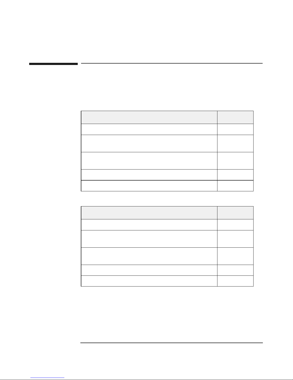
Table 1-1 DLT Drive Upgrade Kit Components
Description Quantity
Drive module 1
SCSI jumper cable with 68-pin differential
connectors
SCSI differential terminator (LVDS or HVDS,
depending on your configuration)
Serial number label 1
Upgrade instructions 1
Table 1-2 Ultrium Drive Upgrade Kit Components
Description Quantity
Drive module 1
SCSI jumper cable with 68-pin differential
connectors
SCSI differential terminator (LVDS or HVDS,
depending on your configuration)
Serial number label 1
1
1
1
1
Upgrade instructions 1
Chapter 11-2
Page 15

Upgrading the Library
Upgrade Kit Components
Fibre Channel Upgrade Kits
Table 1-3 Standard Performance Fibre Channel Upgrade Kit (LVDS and
HVDS)
Description Quantity
Fibre Channel card (LVDS or HVDS) 1
Jumper cables with 68-pin differential connectors 2
Fibre Channel cable 1
Upgrading the Library
GBIC that connects the Fibre Channel card to the
2
Fibre Channel loop
Serial number label 1
Upgrade instructions 1
Table 1-4 High Performance Fibre Channel Upgrade Kit (LVDS)
Description Quantity
Fibre Channel card (LVDS) 1
Jumper cables with 68-pin high-density differential
2
connectors
Fibre Channel cable 1
Serial number label 1
Upgrade instructions 1
Chapter 1 1-3
Page 16
Upgrading the Library
Upgrade Kit Components
Redundant Power Supply Upgrade Kit
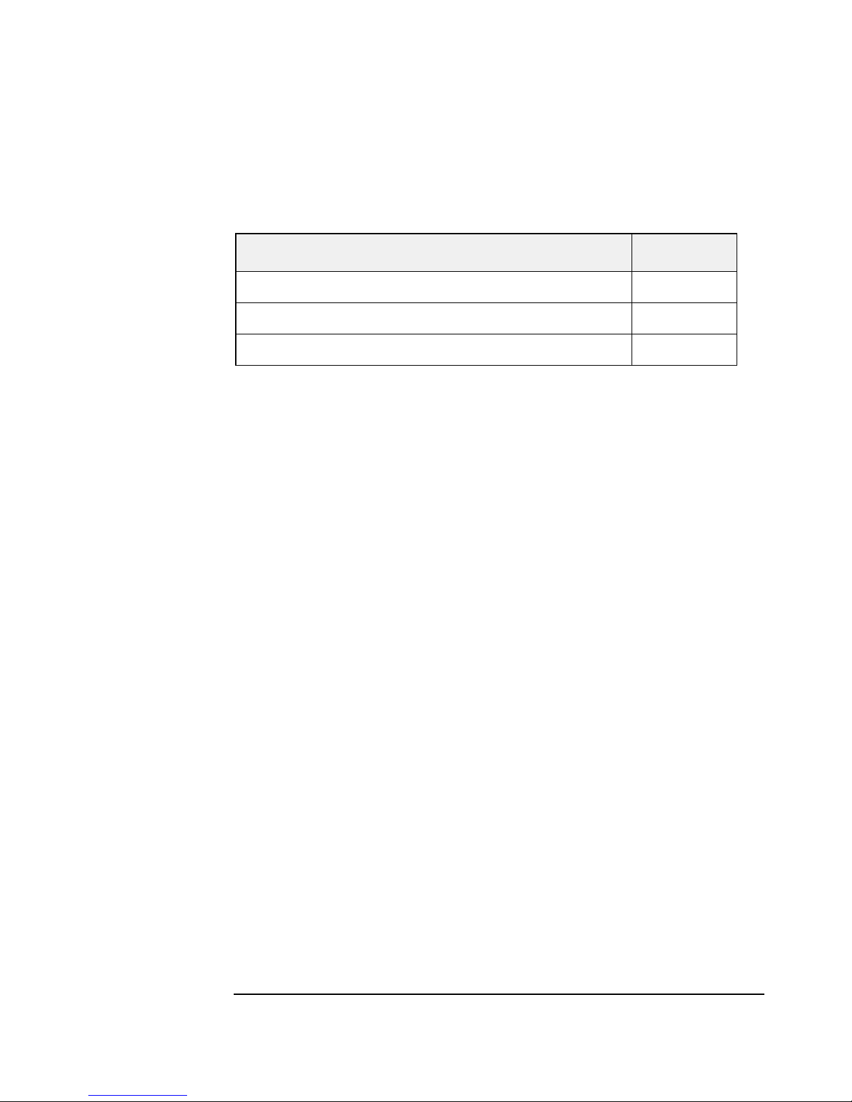
Table 1-5 Redundant Power Supply Upgrade Kit
Description Quantity
Power supply module enclosure 1
Individual power supply units 2
Upgrade instructions 1
Chapter 11-4
Page 17

Upgrading the Library
Upgrading Drive Capacity
Upgrading Drive Capacity
Remember to:
❏ Ensure you are installing the same drive type on each level of the
library. Each level should only contain DLT or Ultrium drives.
❏ If you have a Fibre Channel library and are adding Ultrium drives
to your library, check that the high performance Fibre Channel
card is installed on the same level as the Ultrium drive to ensure
appropriate throughput (see Table 3-7 on page 3-14 and Table 3-8
on page 3-15 for more information on these cards).
This procedure includes information for adding DLT and/or Ultrium
drives to your existing library.
Upgrading the Library
Upgrading Firmware
If you are adding Ultrium drives to your existing DLT library, you need
to download firmware first before adding the new drive module. Older
versions of firmware may not be compatible with Ultrium components.
See “Upgrading Firmware” on page 3-2 for the procedure.
Installing a Drive Module
NOTE Yu may need to power cycle the host to use the new drive. Refer to the
backup software or operating system documentation for more
information.
1. Select the drive location, and remove the vacant drive slot cover by
removing the two 6-32 T-15 screws with a Torx screwdriver.
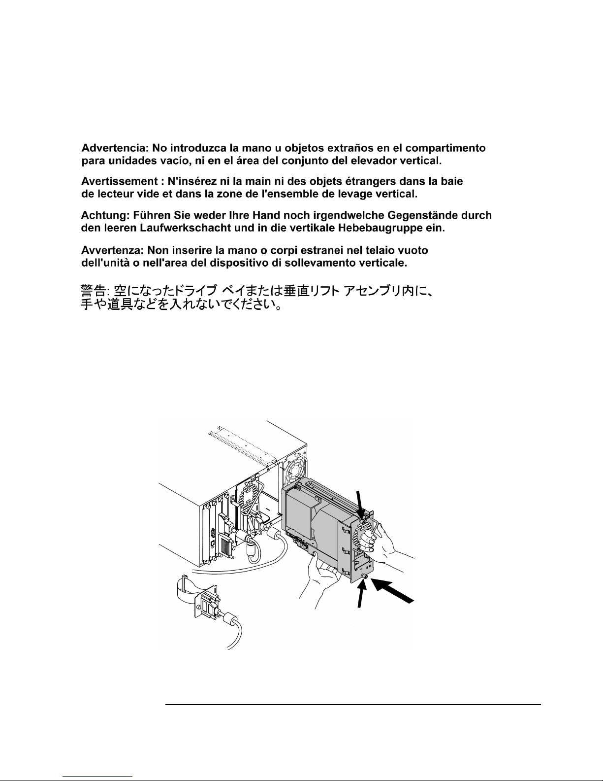
WARNING Do not insert your hand or foreign objects through the empty
drive bay and into the vertical lift assembly area.
Chapter 1 1-5
Page 18
Upgrading the Library
Upgrading Drive Capacity
2. Hold the drive module with one hand on the drive module handle,
while the other hand supports the bottom (Figure 1-1).
3. Install the drive by inserting the rail at the top of the drive module
into the slot at the top of the drive module opening in the library.
Figure 1-1 Installing a Drive Module
4. Tighten the top and bottom thumbscrews, securing the drive module
to the library.
Chapter 11-6
Page 19

Upgrading the Library
Upgrading Drive Capacity
5. Connect the external cables and terminator to the drive.
• For SCSI configurations: Daisy-chain the library controller to
the first (left) drive. Connect each subsequent drive to the host
interface card so that it each drive is on its own bus. Terminate
the library controller and the right drive. (See Figure 1-2 on page
1-8 for an example.)
• For Fibre configurations: See Figure 1-3 on page 1-9 for an
example of how to cable a Fibre Channel library and page A-4 for
front panel configuration information.
6. Add the upgrade serial number label to the pull-out tab on the back of
the library. Apply this label to the tape library to ensure proper
identification of any upgrades.
Upgrading the Library
Chapter 1 1-7
Page 20
Upgrading the Library
Upgrading Drive Capacity
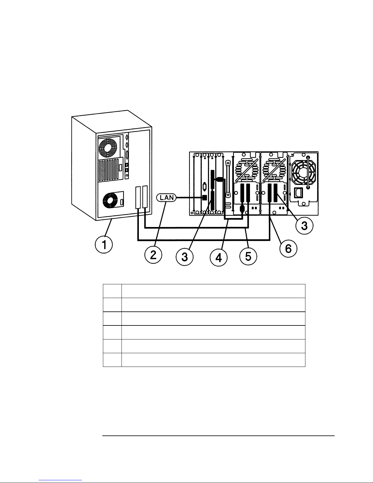
Figure 1-2 Example of SCSI Cable Connections (Model 2/20)
1 Host (user configured)
2 Remote management card LAN connection
3 Appropriate 68-pin SCSI terminator
4 Jumper cable with SCSI 68-pin connectors
5SCSI cable from drive 1 to host
6 SCSI cable from drive 2 to host
Chapter 11-8
Page 21
Upgrading the Library
Upgrading Drive Capacity
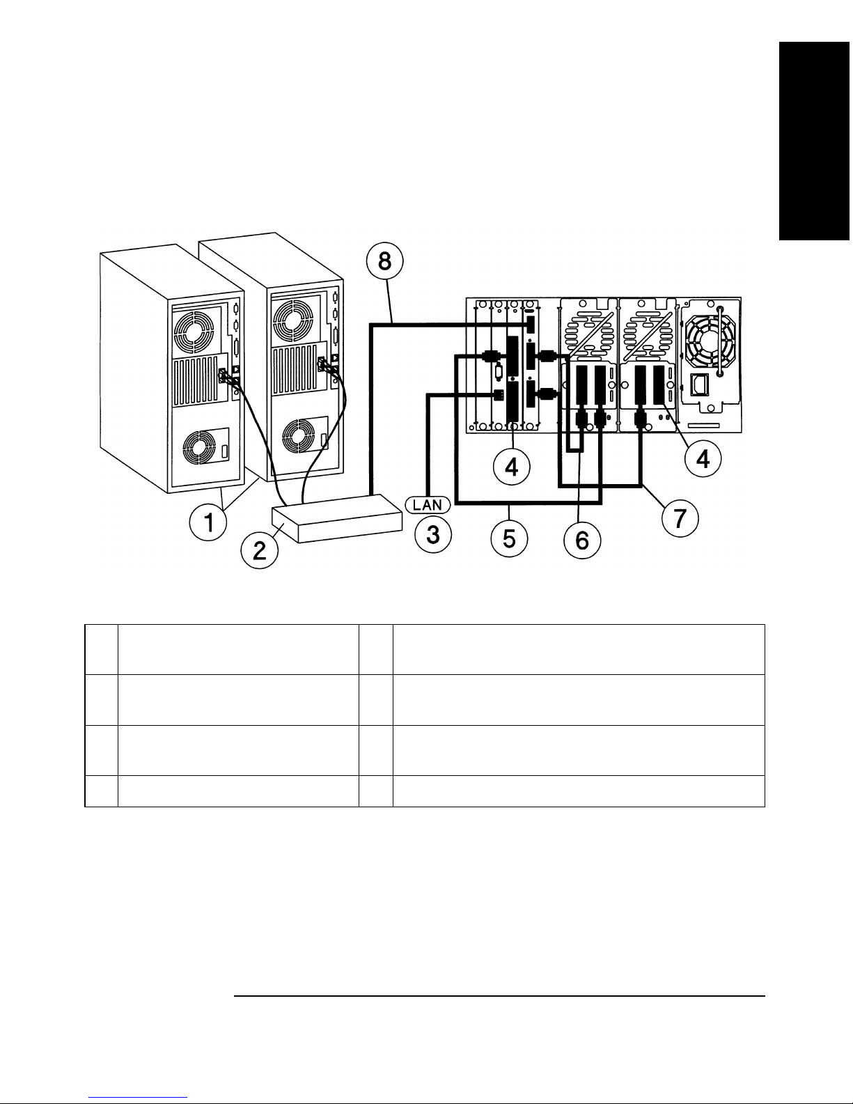
Figure 1-3 Example of Fibre Channel Connections (Model 2/20)
Upgrading the Library
1 Hosts (user configured) 5 SCSI cable from the library controller card to
drive 1
2 Hub or switch 6 SCSI cable from bus 1 on the Fibre Channel
controller card to drive 1
3 Remote management card
LAN connection
7 SCSI cable from bus 2 on the Fibre Channel
controller card to drive 2
4 Appropriate SCSI terminator 8 Fibre Channel cable to hub or switch
Chapter 1 1-9
Page 22

Upgrading the Library
Upgrading Drive Capacity
Configuring the New Drive
NOTE You may need to use the host backup software to recognize the new drive
when bringing it online. If the software or operating system does not have
the capability to automatically detect the new drive, you may need to
reboot.
Bring the new drive module online using the front panel display.
1. Enter the
2. Specify which drive module has been added, and press
3. Select
Administration then the Online Drive Repair menus.
[OK].
[Put drive online].
4. If you have increased the number of drives since the last power cycle,
you must power cycle the library for it to recognize the additional
drives.
The library will automatically run a self-test to check the inventory
when the drive has been brought online. When the drive is
successfully brought online, the new drive will adopt the SCSI ID of
the current drive position. The LED on the back of the drive will be
green. See Table 3-6 on page 3-13 for more information on drive
LEDs.
NOTE If you have two or more of the same drive type with different firmware
revisions, the library will go into a partial availability state due to a
firmware mismatch. When this occurs, the front panel will display
Available
, and the LED bar beneath the front panel display will be solid
Partly
amber. Download new drive firmware to ensure all the drives are using
the same firmware revision. If you are still getting the
Partly Available
message, consult your user guide or service manual for potential causes.
Chapter 11-10
Page 23

Upgrading the Library
Adding Fibre Channel or Remote Management Cards
Adding Fibre Channel or Remote
Management Cards
Remember to:
❏ Use high-performance Fibre Channel cards on any level of the
library that contains Ultrium drives. See Table 3-7 on page 3-14
and Table 3-8 on page 3-15 for an illustration of the highperformance and standard-performance Fibre Channel cards.
CAUTION This library contains very sensitive electrical components. It is important
to follow the proper procedures to prevent electrostatic discharge (ESD).
Use wrist-grounding straps and anti-static mats when removing and
replacing cards and major assemblies.
Upgrading the Library
Failure to follow proper procedures could lead to intermittent failures or
premature hard failures.
CAUTION The Fibre Channel printed circuit boards contains a laser system that is
classified as a “Class-I Laser Product” under a U.S. Department of Health
and Human Services (DHHS) Radiation Performance standard according
to the Radiation Control for Health and Safety Act of 1968 and EN608251(+A11) safety of laser products.
Chapter 1 1-11
Page 24
Upgrading the Library
Adding Fibre Channel or Remote Management Cards
NOTE Before powering the library off to remove a card from the library, review
the LEDs on the back of each card to ensure there is no activity. See
Figure 1-4 and “Back Panel LEDs” on page 3-8.
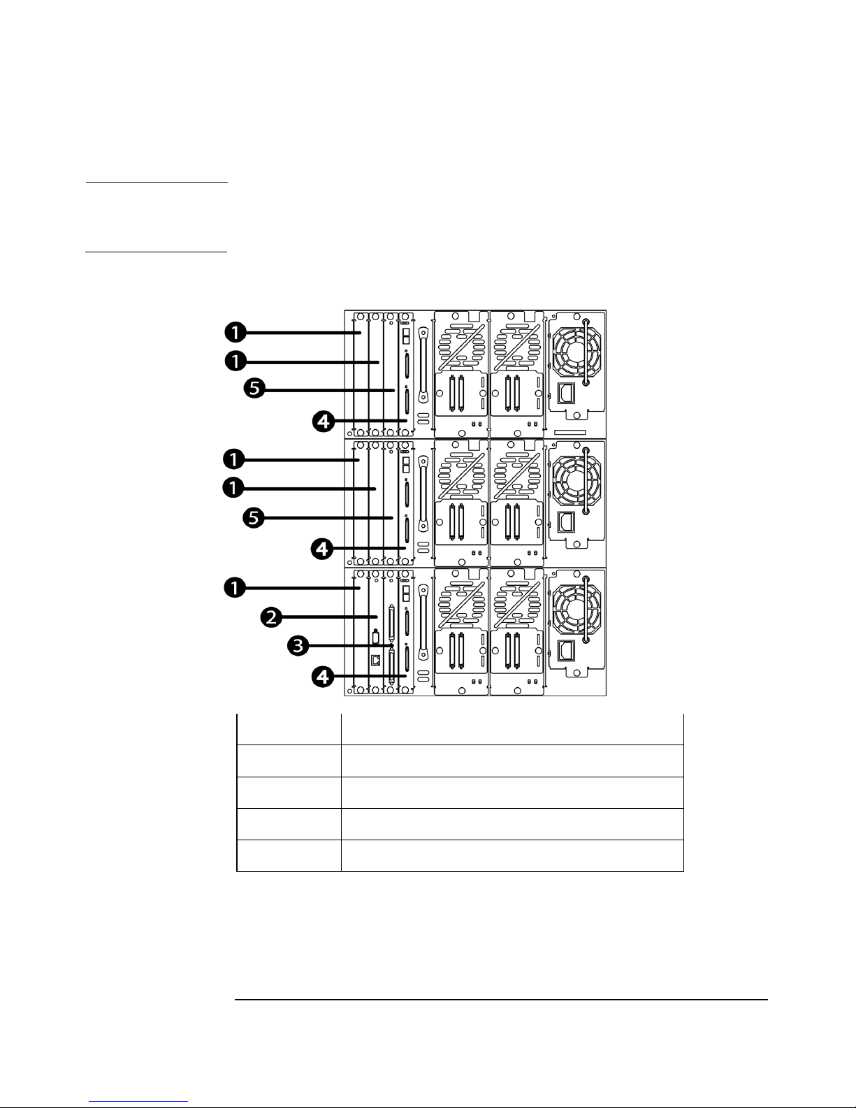
Figure 1-4 Library Card Positions
1 Vacant slot
2 Remote management card
3 Library controller card
4 Fibre Channel card
5 Slave controller card
Chapter 11-12
Page 25

Upgrading the Library
Adding Fibre Channel or Remote Management Cards
To add a card to the library:
1. Power off the library.
2. Select the appropriate location for the card, and remove the vacant
slot cover. See Figure 1-4 on page 1-12.
3. Align the top and bottom edges of the card you are adding with the
card slot.
4. Gently push the card into the library until the card is flush with the
library.
5. Tighten the thumbscrews (finger tight).
6. Connect external cable(s).
7. Add the upgrade serial number label to the pull-out tab on the back of
the library. Apply this label to the tape library to ensure proper
identification of any upgrades you do.
Upgrading the Library
8. Power on the library.
NOTE If the new card has a different version of firmware than the library, the
library could go into a partial availability state due to a firmware
mismatch. In this state, the front panel will display
Partly Available, and
the LED bar beneath the front panel display will be solid amber. If this
occurs, then download the most recent library firmware (See “Upgrading
Firmware” on page 3-2.)
9. If installing Fibre Channel or remote management cards, configure
the new card from the library front panel. See Appendix A,
Configuring the Library for more information.
Chapter 1 1-13
Page 26

Upgrading the Library
Upgrading to a Redundant Power Supply
Upgrading to a Redundant Power Supply
Remember to:
❏ If you are adding redundant power to your library, you need to use
redundant power supplies on all library levels. All power supplies
must either be redundant or standard. Mixed power supplies are
not supported.
1. Disconnect all power cords from the library.
2. Remove the power supply that is shipped with the library by
loosening the two thumbscrews screws and pulling the module
straight out (see Figure 1-5 on page 1-15).
3. Install the redundant power supply module by aligning the bottom of
the module with the bottom of the power supply bay (see Figure 1-5
on page 1-15).
4. Fully insert the power supply module into the back of the power
supply bay.
5. Tighten the two 6-32 x .25 T15 screws to secure the module to the
library.
6. Reconnect the power cords to the bottom of the power supplies.
7. Ensure the individual power supply units are fully installed inside
the power supply module. The LEDs on each supply will be solid
green when the supply is online. See Table 3-9 on page 3-16 for more
information on the power supply LEDs.
Chapter 11-14
Page 27
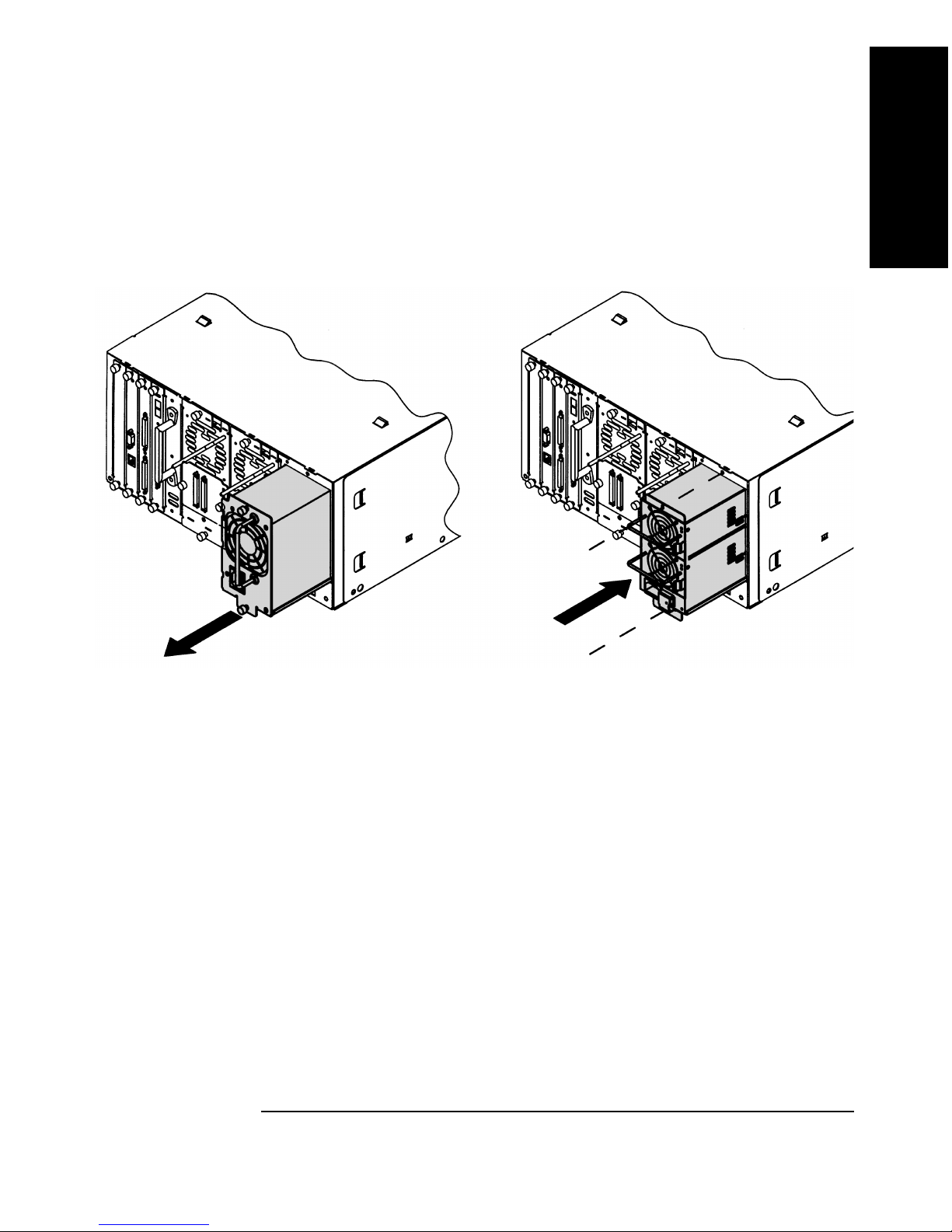
Upgrading to a Redundant Power Supply
Figure 1-5 Adding the Redundant Power Supply Module
Upgrading the Library
Upgrading the Library
Chapter 1 1-15
Page 28

Upgrading the Library
Upgrading to a Redundant Power Supply
Chapter 11-16
Page 29

Replacing Library Parts
2 Removing and Replacing Major
Library Components
Each replacement procedure is rated on how difficult it is to correctly
perform this procedure. [1]: Easiest -> [3] Moderate -> [5] Most Difficult
Chapter 2 2-1
Page 30
Removing and Replacing Major Library Components
Overview
Overview
NOTE For the purpose of this documentation, we will use the term Model 12/140
to indicate all library models that are five levels and higher. These models
include: 4/100, 6/100, 6/120, and 6/140, 8/140, 10/140, and 12/140.
Most library parts that are used in Model 12/140 are the same as Models
2/20, 4/40, and 6/60. The procedures for replacing these common parts
are documented in this chapter with exceptions noted where applicable
Some parts are unique to Model 12/140. These differences are because of
the library’s increased size and the custom cabinet. Table 2-1 provides an
overview of common parts and unique parts.
Table 2-1 Common and Unique Parts
Replacement Procedures
Common for all Library
Models
Front panel display (page 2-67) 12/140 Transport assembly
Vertical lift assembly (not used
on Model 2/20) (page 2-48)
Power supply (page 2-59) Library side panels (page 2-36
Fibre Channel, remote
management, slave controller,
and library controller cards
(page 2-18)
Replacement Procedures
Unique to Library Model
12/140
(page 2-36)
Note: Includes a different
procedure for accessing the
library for service
See page 2-28 for information
on the 2/20, 4/40, 6/60 transport
assembly.
Power distribution unit
(page 2-65)
and Figure 2-28 on page 2-55)
Library cabinet (page 2-36)
Chapter 22-2
Page 31

Removing and Replacing Major Library Components
Table 2-1 Common and Unique Parts
Overview
Replacement Procedures
Common for all Library
Models
Replacement Procedures
Unique to Library Model
12/140
Drive modules (page 2-21) Library expansion card (page 2-
18 and page 2-16)
Motherboard (page 2-50)
Cosmetic door (page 2-70)
Redundant power supply (page
2-61)
Replacing Library Parts
Chapter 2 2-3
Page 32

Removing and Replacing Major Library Components
Exploded Views of Replaceable Parts (FRUs)
Exploded Views of Replaceable Parts (FRUs)
The exploded views are categorized into the following sections:
• Front and Back FRUs: These parts are accessed from the front or
back of the library and include:
— Cards
— Drive
— External cables (cables, terminator, GBIC)
— Display (RFI shield, display, and viewing windows)
— Power supply
• Cosmetic and Sheetmetal FRUs: These parts are primarily
accessed on the outside of the library and include:
— Side panels
— Top and bottom covers
— Cosmetic doors and door trays
— Magazine
— Lifting straps
— Standalone feet
— Transport assembly
• Internal FRUs: This exploded view illustrates parts that are found
inside the library.
• Model 12/140 FRUs: This exploded view shows parts that are
unique to this larger library. The majority of parts in this library are
the same as the primary and secondary FRUs. Table 2-1 on page 2-2
compares the common and unique parts for Model 12/140.
Chapter 22-4
Page 33

Removing and Replacing Major Library Components
Exploded Views of Replaceable Parts (FRUs)
Front and Back FRUs
Figure 2-1 Exploded View of Front and Back FRUs
Replacing Library Parts
Chapter 2 2-5
Page 34

Removing and Replacing Major Library Components
Exploded Views of Replaceable Parts (FRUs)
Table 2-2 Description of Front and Back FRUs
Callout #
FRU
ID
Description
1 N/A Vacant drive module cover: Uses two 6-32 screws to attach.
2 32 Standard power supply (see page 2-59 for more information).
3 32 Redundant power supply: Uses 6-32 x .25 T15 screws to attach (see
page 2-61 for more information).
Note: Libraries should only contain all redundant or standard power
supplies. The illustration is for identification purposes only.
42• DLT LVDS tape drive module.
• DLT HVDS tape drive module.
• Ultrium LVDS tape drive module.
• Ultrium HVDS tape drive module.
(See page 2-21 for more information on drive replacement.)
562• DLT or Ultrium LVDS online drive repair SCSI loop cable (included
in cable kit).
• DLT or Ultrium HVDS online drive repair SCSI loop cable (included
in cable kit).
6 6 Slave controller for all models, except Model 2/20 (see page 2-18 for
more information).
7 N/A Vacant card slot cover.
8 7 Remote management card assembly (see page 2-18 for more
information).
91• Low Voltage Differential SCSI (LVDS) library controller.
• High Voltage Differential SCSI (HVDS) library controller.
(See page 2-18 for more information on card replacement.)
Chapter 22-6
Page 35

Removing and Replacing Major Library Components
Exploded Views of Replaceable Parts (FRUs)
Table 2-2 Description of Front and Back FRUs
Callout #
FRU
ID
Description
10 9 • Standard performance HVDS Fibre Channel board.
• Standard performance LVDS Fibre Channel board.
• High performance HVDS Fibre Channel board.
• High performance LVDS Fibre Channel board.
(See page 2-18 for more information.)
11 N/A RFI front panel display shield. Includes two 6-32 x .25 screws.
12 22 Front panel display: Uses 6-32 x 1.0 screws to attach (see page 2-67 for
more information).
13 N/A Display window frame and viewing window (see Figure 2-36 on page 2-
68). Uses 6-32 machine screws to attach.
14 N/A Viewing window assembly. Uses 6-32 screws to attach. See “Removing
and Replacing the Front Panel Display” on page 2-67.
15 N/A RFI front panel display shield. Includes two 6-32 x .25 screws.
Replacing Library Parts
16 N/A Fibre Channel GBIC. Only used on standard-performance Fibre
Channel boards.
17 59 • External 68-pin daisy-chain cable.
• External VHD daisy-chain cable
18 N/A Fibre Channel cable.
19 N/A • Fast wide SCSI terminator.
• SCSI LVDS terminator.
20 59 SCSI interface cable.
Chapter 2 2-7
Page 36

Removing and Replacing Major Library Components
Exploded Views of Replaceable Parts (FRUs)
Cosmetic and Sheetmetal FRUs
Figure 2-2 Cosmetic and Sheetmetal Exploded View (1 of 2)
Chapter 22-8
Page 37

Removing and Replacing Major Library Components
Exploded Views of Replaceable Parts (FRUs)
Table 2-3 Description of Cosmetic and Sheetmetal FRUs (1 of 2)
Callout #
FRU
ID
Description
1 27 Transport assembly (see page 2-28 for more information).
2 N/A Library side panel for Models 2/20, 4/40, and 6/60 (left back, when
viewing from the front of the library). Uses #4 - 40 x. 312 screws to
attach. (See Figure 2-28 on page 2-55.)
3 N/A Library side panel for Models 2/20, 4/40, and 6/60 (left front, when
viewing from the front of the library). Uses #4 - 40 x. 312 screws to
attach. (See Figure 2-28 on page 2-55.)
4N/A• Empty DLT magazine.
• Empty Ultrium magazine.
5 N/A Left door tray assembly (remove the left side panel and unscrew the six
6-32 x .375 T-15 screws that connect the tray assembly to the chassis).
6N/A• Left cosmetic door (see page 2-70).
• Right cosmetic door (see page 2-70).
7 N/A Right door tray assembly (remove the right side panel and unscrew the
six 6-32 x .375 T-15 screws that connect the tray assembly to the
chassis).
Replacing Library Parts
8 N/A Bottom cover.
9 N/A Library side panel for Models 2/20, 4/40, and 6/60 (right front, when
viewing from the front of the library), see Figure 2-28 on page 2-55.
Uses #4 - 40 x. 312 screws to attach.
10 N/A Library side panel for Models 2/20, 4/40, and 6/60 (right back, when
viewing from the front of the library), see Figure 2-28 on page 2-55.
Uses #4 - 40 x. 312 screws to attach.
Chapter 2 2-9
Page 38

Removing and Replacing Major Library Components
Exploded Views of Replaceable Parts (FRUs)
Figure 2-3 Exploded View of Cosmetic and Sheetmetal FRUs (2 of 2)
Chapter 22-10
Page 39

Removing and Replacing Major Library Components
Exploded Views of Replaceable Parts (FRUs)
Table 2-4 Description of Cosmetic and Sheetmetal FRUs (2 of 2)
Callout # Description
1 Library top cover for Model 2/20 (see Figure 2-12 on page 2-31). Includes
eight #4 - 40 x .25 screws to attach.
2 Bezel chin for the lowest library level. Uses 6-32 machine screws to attach.
3 Forehead for library Model 4/40 (see Figure 2-12 on page 2-31). Installed at
the top of the library with four 10-24 T-25 screws.
4 Bezel chin. See “Removing and Replacing the Front Panel Display” on page
2-67. Uses 6-32 machine screws to attach.
5 Forehead for library Models 6/60 and 12/140 (see Figure 2-12 on page 2-31).
Installed at the top of the library with four 10-24 T-25 screws.
6 Lifting strap (used to guide libraries into a rack). Uses 10-24 x .50 screws to
attach.
7 Lifting strap (used to guide libraries into a rack). Uses 10-24 x .50 screws to
attach.
8 Lifting strap for enterprise libraries. Uses 10-24 x .50 screws to attach.
9 Vertical lift cover for multi-level libraries (see Figure 2-12 on page 2-31).
Installed at the top of the library with two 10-24 x .50 screws.
Replacing Library Parts
10 Standalone feet. Includes four 10-24 x .50 screws to attach.
11 Standalone cover assembly for Model 2/20: Uses #10-24 x .625 screws to
attach.
Chapter 2 2-11
Page 40

Removing and Replacing Major Library Components
Exploded Views of Replaceable Parts (FRUs)
Internal FRUs
Figure 2-4 Exploded View of Internal FRUs (1 of 2)
Chapter 22-12
Page 41

Removing and Replacing Major Library Components
Exploded Views of Replaceable Parts (FRUs)
Table 2-5 Description of Internal FRUs (1 of 2)
Call-
FRU ID Description
out #
1 N/A Back gear rail without stop for multi-level libraries. Install this part
by removing all drives and installing the rails from the back of the
library. Two 6-19 x .5 screws secure the top and bottom of the rail to
the library chassis. On the lowest library level, you will have to
remove the transport assembly to access this part (see “Accessing the
Side Panels for Service” on page 2-36).
2 N/A Front gear rail without stop for multi-level libraries. Install this part
by removing the viewing window from the front of the library. Two 619 x .5 screws secure the top and bottom of the rail to the library
chassis. On the lowest library level, you will have to remove the
transport assembly to access this part (see “Accessing the Side Panels
for Service” on page 2-36).
3 N/A Back gear rail with stop (packaged with front and upper gear rails
and accessed by removing the drives).
4 N/A Front gear rail with stop (packaged with back and upper gear rails
and accessed by removing the front viewing window).
5 N/A Left magazine lock assembly. Includes the door tray detecting switch.
Access this part by removing the panels on the left side of the library.
Two 6-32 x .375 T-15 screws secure this assembly to the library
chassis. Avoid damaging the cables and connectors.
Replacing Library Parts
6 N/A Right magazine lock assembly. Includes the door tray detecting
switch Access this part by removing the panels on the right side of the
library. Two 6-32 x .375 T-15 screws secure this assembly to the
library chassis. Avoid damaging the cables and connectors.
7 24 Vertical lift assembly: Uses #6-19 x .5 screws to attach (see page 2-48
for more information).
Chapter 2 2-13
Page 42

Removing and Replacing Major Library Components
Exploded Views of Replaceable Parts (FRUs)
Figure 2-5 Exploded View of Internal FRUs (2 of 2)
Chapter 22-14
Page 43

Removing and Replacing Major Library Components
Exploded Views of Replaceable Parts (FRUs)
Table 2-6 Description of Internal FRUs (2 of 2)
Callout #FRU ID Description
1 65 Display cable (included in cable kit). Access this part by
removing the library side panels. The display cable needs to be
threaded underneath the right door tray rail to connect to the
motherboard (see Figure 2-25 on page 2-51). Do not connect the
display cable on all levels; only connect the cable located on the
level with the display.
2 N/A Power switch cable (included in cable kit). Access this part by
removing the chin plate on the front and at the bottom of the
library and the right side panel on the lowest library level.
3 N/A Mailslot solenoid assembly: Two #4-40 x .375 T-10 screws
secure this part to the inside edge of the library. Remove the
library side panels to access this part.
4 N/A Magazine lock harness cable (included in cable kit), see Figure
2-29 on page 2-56. Access this part by removing the library side
panels. Secure the cable to the side of the library chassis to
ensure it does not become damaged.
5 N/A Interconnect cable that connects multi-level libraries (included
in cable kit, see Figure 2-25 on page 2-51).
Replacing Library Parts
6 48 Chassis fan: Remove all cards from the back of the library.
Remove the four 6-32 T-15 screws that secure the fan inside the
back of the library.
7 3 Motherboard: Uses #4-40 x .625 screws to attach (see page 2-50
for more information).
Chapter 2 2-15
Page 44

Removing and Replacing Major Library Components
Exploded Views of Replaceable Parts (FRUs)
Model 12/140 FRUs
Figure 2-6 Unique FRUs for Model 12/140
Chapter 22-16
Page 45

Removing and Replacing Major Library Components
Exploded Views of Replaceable Parts (FRUs)
Table 2-7 Unique Parts for Model 12/140 (5 of 5)
Callout #Description
1Top panel.
2 Filler panel. The panel is spring loaded at the top of the library cabinet when
there is space at the top of the cabinet.
3 Side panels. Use a 3/16 Allen wrench to remove the four captive fasteners on
each side panel. See “Accessing the Side Panels for Service” on page 2-36.
4 Library expansion card, which is located on level 5 of the library (see page 2-
18 for more information).
5 • Front side panels on library: Uses 4-40 screws to attach. See “Accessing
the Side Panels for Service” on page 2-36.
• Back side panels on library: Uses 4-40 screws to attach. See “Accessing the
Side Panels for Service” on page 2-36.
6 Lift cover bottom panel. Two captive T-20 bit screws (one on each side) secure
the panel to the cabinet. See “Accessing the Side Panels for Service” on page
2-36.
7 Lift assembly with jack and handwheel.
Replacing Library Parts
8 Power distribution unit: Uses 10-32 screws to attach. See “Removing and
Replacing the Power Distribution Unit (for Model 12/140 only)” on page 2-65.
NOTE Not all the parts listed above are set up as FRUs (Field Replaceable
Units). Some of these components are service parts that are not stocked.
Chapter 2 2-17
Page 46

Removing and Replacing Major Library Components
Removing and Replacing Cards
Removing and Replacing Cards
Level of Difficulty: [1] Easy
CAUTION This library contains very sensitive electronic components. It is important
to follow the proper procedures to prevent electrostatic discharge (ESD).
Use wrist-grounding straps and anti-static mats when removing and
replacing cards and major assemblies.
Failure to follow proper procedures could lead to intermittent failures or
premature hard failures.
CAUTION The Fibre Channel printed circuit boards contains a laser system that is
classified as a “Class-I Laser Product” under a U.S. Department of Health
and Human Services (DHHS) Radiation Performance standard according
to the Radiation Control for Health and Safety Act of 1968 and EN608251(+A11) safety of laser products.
Removing a Card
1. Review the LEDs on the back of each card to ensure there is no
activity on the card (see “Library LEDs” on page 3-7).
2. Note the library front panel configuration settings (if you will be
replacing the controller card), and power off the library. These
settings include:
• Password
• Network Access
• Mailslot
• Fibre Channel or SCSI IDs
3. Power off the library. Do not remove cards while the library is
powered on.
4. Note how the library is cabled and the position of the card.
5. Remove all external cables attached to the card.
Chapter 22-18
Page 47

Removing and Replacing Major Library Components
Removing and Replacing Cards
6. Loosen the two thumbscrews on the card with a screwdriver or by
hand.
7. Remove the card by pulling it outward.
Replacing a Card
1. Align the top and bottom edges of the replacement card with the card
slots.
2. Gently push the replacement card into the library until the card is
flush with the library.
3. Tighten the thumbscrews (finger tight).
4. Reconnect the external cables.
5. Power on the library.
6. Download new firmware. See “Upgrading Firmware” on page 3-2
Replacing Library Parts
NOTE If the new card has a different version of firmware than the rest of the
library, the library could go into a partial availability state due to a
firmware mismatch. When this occurs, the front panel will display
Available
, and the LED bar beneath the front panel display will be solid
Partly
amber. This is not an indication of a failure, but indicates that you need
to download new library firmware.
7. Configure the library.
• If installing a remote management card, see “Configuring the
Remote Management Card” on page A-2.
• If installing Fibre Channel, you may need to configure the library
from the front panel. See “Configuring the Library for Fibre
Channel” on page A-4 for more information.
Chapter 2 2-19
Page 48

Removing and Replacing Major Library Components
Removing and Replacing Cards
Figure 2-7 Library Card Positions
1 Vacant slot 4 Fibre Channel card
2 Remote management card 5 Slave controller card 8 Power supply
3 Library controller card 6 Library expansion card 9 Product information labels
7 Empty drive bay
(optional)
Chapter 22-20
Page 49

Removing and Replacing Major Library Components
Removing and Replacing Drive Modules
Removing and Replacing Drive Modules
Level of Difficulty: [2] Easy to Moderate
A drive module may be replaced in either of the following situations:
• The library is powered off during drive replacement, and the SCSI
bus chain is disconnected.
• The library is connected to the host and the backup software can
access the functional drives. Though drives can be replaced without
disabling or interrupting most functions of the library, this feature
must be supported by the backup software. (If you download new
drive firmware, power cycle to activate the new firmware.)
NOTE If you are adding Ultrium drives to an existing DLT library, follow the
upgrade procedure on page 1-5.
Drive Replacement Overview
These steps are documented in more detail on the following pages.
1. Determine which drive has failed (if you are replacing a failed drive).
Replacing Library Parts
2. Unload a tape from the drive, if possible.
3. Take the drive module offline (drive module only; the library does not
need to be powered off).
4. Remove the drive module.
5. Insert and connect the new drive module.
6. Bring the drive back online.
NOTE If the new drive has a different firmware revision than the drives that are
already in the library, the library could go into a partial availability state
due to a firmware mismatch. When this occurs, the front panel will
display
will be solid amber. Download new drive firmware until all drives have
the same firmware revision.
Chapter 2 2-21
Partly Available, and the LED bar beneath the front panel display
Page 50

Removing and Replacing Major Library Components
Removing and Replacing Drive Modules
Determining Which Drive Has Failed
If a drive has failed or had an error, the following can happen:
• The icons on the library front panel indicate a drive with an error.
• The LEDs on the drive indicate an error.
• The library attempts to take the drive offline.
• The host indicates an error.
Unloading a Tape from a Drive
Before replacing a drive, unload any tape from the drive.
1. From the
Drive]
2. Use the
3. Select
Drive and Tape Operations menu, select [Unload Tape from
.
[+] or [-] keys to select the drive you want to unload.
[Unload] to move the tape from the drive module to the original
slot where the tape was located. The tape is automatically rewound
before it is unloaded.
If you are unable to unload a tape from a failed drive, continue to the
next section below.
Taking a Drive Offline
Although a drive module can be removed without powering off the
library, you must first take the drive module offline. This process may be
accomplished using the library’s front panel and following these steps:
1. Check the drive icons on the front panel display to see if the drive has
already been taken offline. Verify the drive’s status by checking the
LEDs on the back of the drive module (see Table 3-6 on page 3-13).
2. If the drive module is not already offline, go to the
Administration and then Online Drive Repair menus. Set the failing
drive to the offline state.
Service or
3. Select the drive with the [-] or [+] keys, and press [OK].
4. Select
failure of this operation. The drive will automatically attempt to
rewind any loaded tape.
[Put Drive Offline]. The front panel indicates the success or
Chapter 22-22
Page 51

Removing and Replacing Major Library Components
Removing and Replacing Drive Modules
Removing a Drive Module
NOTE To preserve SCSI communications, do not loosen or remove the SCSI
cable(s) connected to the outside of the drive module. The connection to be
removed is located inside the drive module.
NOTE When the drive module has been successfully taken offline, one of the
LEDs on the back of the drive will be flashing yellow.
Remove the drive module using the steps below:
1. Verify the external SCSI cable is secured to the connector plate.
2. Loosen the thumbscrews on each side of the connector plate, located
in the middle of the drive module (Figure 2-8).
3. Gently remove the connector plate with SCSI cable(s) still connected.
Replacing Library Parts
CAUTION Use standard precautions for electro-static discharge (ESD) protection.
4. Grasp the ribbon cable that is plugged into the drive module. Remove
the cable by gently pulling the connector to the left (see Figure 2-8).
Figure 2-8 Ribbon Cable and Connector
Chapter 2 2-23
Page 52

Removing and Replacing Major Library Components
Removing and Replacing Drive Modules
5. Lay the connector assembly to the side, allowing the external cables
to hang from the connection(s). Do not disconnect external cables from
the connector plate.
6. Loosen the top and bottom thumbscrews on the drive module (see
Figure 2-9).
7. Using the handle that is mounted on the back of the drive module,
pull the drive module straight out with one hand while supporting
the bottom of the drive module with the other hand.
CAUTION As the drive module is pulled out, support the bottom of the drive module
to avoid dropping or damaging it.
Figure 2-9 Removing a Drive
Chapter 22-24
Page 53

Removing and Replacing Major Library Components
Removing and Replacing Drive Modules
WARNING Do not insert your hand or foreign objects through the empty
drive bay and into the vertical lift assembly area.
Replacing Library Parts
Chapter 2 2-25
Page 54

Removing and Replacing Major Library Components
Removing and Replacing Drive Modules
Installing a Drive Module
1. Hold the drive module with one hand on the drive module handle
while the other hand supports the bottom (Figure 2-10).
2. Install the drive by inserting the rail at the top of the drive module
into the slot at the top of the drive module opening.
Figure 2-10 Installing a Drive Module
Chapter 22-26
Page 55

Removing and Replacing Major Library Components
Removing and Replacing Drive Modules
3. Tighten the top and bottom thumbscrews, securing the drive module
into the library.
4. Reconnect the ribbon connector back inside the drive module (Figure
2-8 on page 2-23).
5. Gently fold the ribbon cable (attached to the plate and SCSI cable)
into the back of the drive module.
6. Holding the connector plate in place, tighten the thumbscrews on
each side of the connector.
7. Bring the new drive module online using the front panel display by
following these steps:
Replacing Library Parts
a. Enter the
Service or Administration then the Online Drive Repair
menus.
b. Select the drive module that has been replaced or installed, and
press
c. Select
[OK].
[Put Drive Online].
d. If you have increased the number of drives since the last power
cycle or if you downloaded new drive firmware, power cycle the
library.
The library will automatically run a self test when the drive has been
brought online.
When the drive is successfully brought online, the new drive will
adopt the SCSI ID of the current drive position. The library will also
confirm the new drive is online in the
Service/Online Drive Repair
menu.
NOTE If the new drive has a different firmware revision than the drives that are
already in the library, the library could go into a partial availability state
due to a firmware mismatch. When this occurs, the front panel will
display
Partly Available, and the LED bar beneath the front panel display
will be solid amber. Download drive firmware until all drives have the
same firmware revision.
NOTE You may need to use the host backup software to recognize the new drive
when bringing it online. If the software does not have the capability to
automatically detect the new drive, you may need to reboot the host.
Chapter 2 2-27
Page 56

Removing and Replacing Major Library Components
Removing and Replacing the Transport Assembly (for Models 2/20, 4/40, and 6/60 only)
Removing and Replacing the Transport
Assembly (for Models 2/20, 4/40, and 6/60 only)
Level of Difficulty: [5] Difficult
NOTE For Model 12/140, refer to page 2-36.
The instructions for this assembly are divided into the following sections:
•“Accessing the Transport Assembly” on page 2-28
•“Removing the Transport Assembly” on page 2-32
•“Replacing the Transport Assembly” on page 2-33
•“Replacing the Cover” on page 2-35
Two Field Replaceable Units (FRUs) are involved with the transport
assembly: the transport assembly and the vertical lift assembly. Either
assembly may be replaced separately, but both must be removed to
replace either one.
Accessing the Transport Assembly
Use the following steps to access the transport assembly:
1. Power off the library.
2. If the library is rackmounted, use the following steps to slide it
forward in the rack:
a. Lower the rack’s lever feet, and fully extend the anti-tip foot at the
bottom front of the rack.
WARNING Failure to extend the anti-tip device could result in personal
injury or damage to the tape library if the rack tips over.
AVERTISSEMENT Si vous ne déployez pas le dispositif antibasculant, le rack risque de
se renverser et de provoquer des blessures ou d’endommager
l’autochargeur de bande.
Chapter 22-28
Page 57

Removing and Replacing Major Library Components
Removing and Replacing the Transport Assembly (for Models 2/20, 4/40, and 6/60 only)
ACHTUNG Wird die Abstützvorrichtung nicht herausgezogen, kann dies zu
Beschädigungen des Autoloaders führen, sollte der
Einschubschrank umkippen.
AVVISO Se non si estende il dispositivo anti-inclinazione, si potrebbero
provocare lesioni personali o danni all’autoloader, in caso di
rovesciamento dello scaffale.
ADVERTENCIA En caso de no abrir el dispositivo estabilizador, existe el peligro de que
se produzcan lesiones personales o daños al cargador automático de
cintas si se vuelca el bastidor.
Replacing Library Parts
b. Pull out the front doors and loosen the screws that secure the
library to the rack.
c. Push the library out until it hits the latch stops.
Chapter 2 2-29
Page 58

Removing and Replacing Major Library Components
Removing and Replacing the Transport Assembly (for Models 2/20, 4/40, and 6/60 only)
3. Remove the stop bracket (Models 4/40 and 6/60 only) by following
these steps:
a. Remove the left back 10-24 T25 screw from the top cover.
b. Remove the stop bracket.
NOTE Model 2/20 does not have a stop bracket.
Figure 2-11 Removing the Stop Bracket for Models 4/40 and 6/60
Chapter 22-30
Page 59

Removing and Replacing Major Library Components
Removing and Replacing the Transport Assembly (for Models 2/20, 4/40, and 6/60 only)
4. Remove the 10-24 screws shown in Figure 2-12 to remove the front
forehead and cover on Models 4/40 and 6/60 and the 4-40 T10 screws
to remove the top cover on Model 2/20. You may have to slide the
cover forward to remove it from the rack.
Figure 2-12 Access to the Transport Assembly
Replacing Library Parts
Chapter 2 2-31
Page 60
Removing and Replacing Major Library Components
Removing and Replacing the Transport Assembly (for Models 2/20, 4/40, and 6/60 only)
Removing the Transport Assembly
Use the following steps to remove the transport assembly:
1. Using the finger-holes in the top of the transport assembly, lift the
assembly up and out of the library (Figure 2-13).
CAUTION Use care to protect the flat, umbilical cable attached to the bottom of the
transport assembly when lifting.
NOTE The illustration on the left is for Models 4/40 and 6/60 and shows the
vertical lift assembly connected to the transport assembly. The
illustration on the right is for Model 2/20, which does not have a vertical
lift assembly.
Figure 2-13 Removing the Transport Assembly
2. Place the transport assembly on top of the library, and disconnect the
umbilical cable from the motherboard by pulling the tabs outward
(Figure 2-13).
Chapter 22-32
Page 61

Removing and Replacing the Transport Assembly (for Models 2/20, 4/40, and 6/60 only)
Replacing the Transport Assembly
1. If you are only replacing the transport assembly, remove the vertical
lift assembly from Models 4/40 and 6/60 to install on the replacement
transport assembly. See “Removing the Vertical Lift Assembly” on
page 2-48 for the procedure.
2. For Models 4/40 and 6/60, remove the 6-19 x .5 screws that secure the
guide blocks to the top of the replacement transport assembly to
reattach the vertical lift assembly (Figure 2-14).
Figure 2-14 Guide Blocks
Removing and Replacing Major Library Components
Replacing Library Parts
3. Connect the umbilical cable to the motherboard (Figure 2-13 on page
2-32). Ensure that it clicks into place.
Chapter 2 2-33
Page 62

Removing and Replacing Major Library Components
Removing and Replacing the Transport Assembly (for Models 2/20, 4/40, and 6/60 only)
4. On Model 2/20, lower the transport assembly into the library,
ensuring that the umbilical cable folds properly as you lower the
assembly.
5. On Models 4/40 and 6/60, align the gears on the transport assembly
with the gear rails on the library (Figure 2-15). Check the gear teeth
position to ensure they are aligned with the gear rails and that the
gear rails are level with each other.
CAUTION On Models 4/40 and 6/60, the alignment of the gears with the gear rails is
critical. The library will test alignment when it is powered on.
Figure 2-15 Transport Assembly Position
A Gears incorrectly aligned 1 Gears
B Gear correctly aligned 2 Gear rails (racks)
6. When the transport assembly is level with the top of the library,
lower it to the bottom of the library.
3 Check points to ensure
alignment
Chapter 22-34
Page 63

Removing and Replacing Major Library Components
Removing and Replacing the Transport Assembly (for Models 2/20, 4/40, and 6/60 only)
Replacing the Cover
1. Replace the top cover.
• For Model 2/20, insert all screws and tighten.
• For Models 4/40 and 6/60, insert the metal tabs of the cover into
the slots on the library (Figure 2-12 on page 2-31). Insert all
screws, and tighten. Align the screw holes in the front forehead
with the holes in the top of the library, insert screws, and tighten.
2. If the library is rackmounted, follow the steps below:
a. Replace the stop bracket. (For Models 4/40 and 6/60 only. See
Figure 2-11 on page 2-30.)
b. Replace the screws behind the front doors that secure the library
in place.
Replacing Library Parts
Chapter 2 2-35
Page 64

Removing and Replacing Major Library Components
Removing and Replacing the Transport Assembly (for Model 12/140 only)
Removing and Replacing the Transport
Assembly (for Model 12/140 only)
Level of Difficulty: [5] Difficult
The transport assembly involves two replaceable parts: the transport
assembly and the vertical lift assembly. Either assembly may be
replaced separately, but both must be removed to service either part. See
page 2-48 for instructions on replacing the vertical lift assembly.
The instructions for replacing the transport assembly are divided into
the following sections:
•“Accessing the Side Panels for Service” on page 2-36
•“Accessing the Transport Assembly” on page 2-40
•“Replacing the Transport Assembly” on page 2-45
•“Replacing the Transport Assembly” on page 2-45
•“Re-installing the Bottom Module” on page 2-46
Accessing the Side Panels for Service
The library can be serviced by removing the side and bottom panels on
the cabinet and library. You will not need to access the top of the library
to service this product.
To access the library from the sides:
1. Extend the anti-tip rails, which are located at the bottom of the
library cabinet. After extending these rails, lower the leveler feet to
keep the library cabinet from moving when you are servicing it.
WARNING Failure to extend the anti-tip device could result in personal
injury or damage to the tape autoloader if the rack tips over.
AVERTISSEMENT Si vous ne déployez pas le dispositif antibasculant, le rack risque de
se renverser et de provoquer des blessures ou d’endommager
l’autochargeur de bande.
Chapter 22-36
Page 65

Removing and Replacing Major Library Components
Removing and Replacing the Transport Assembly (for Model 12/140 only)
ACHTUNG Wird die Abstützvorrichtung nicht herausgezogen, kann dies zu
Beschädigungen des Autoloaders führen, sollte der
Einschubschrank umkippen.
AVVISO Se non si estende il dispositivo anti-inclinazione, si potrebbero
provocare lesioni personali o danni all’autoloader, in caso di
rovesciamento dello scaffale.
ADVERTENCIA En caso de no abrir el dispositivo estabilizador, existe el peligro de que
se produzcan lesiones personales o daños al cargador automático de
cintas si se vuelca el bastidor.
Replacing Library Parts
2. Use a 3/16 Allen wrench to remove the side panels from the cabinet
by following these steps (see Figure 2-16 on page 2-38):
a. Loosen the four captive fasteners that secure each side panel to
the cabinet. Hold the panel in place when removing the last screw.
b. Support the panel to lift it slightly up then lower it down.
c. Remove the other side panel using the same procedure.
Chapter 2 2-37
Page 66

Removing and Replacing Major Library Components
Removing and Replacing the Transport Assembly (for Model 12/140 only)
3. Remove the cosmetic panel from the bottom of the library. Loosen the
captive T-20 screws on each side of the panel and pull it straight out.
Figure 2-16 Removing the Cabinet Side Panels
Chapter 22-38
Page 67

Removing and Replacing Major Library Components
Removing and Replacing the Transport Assembly (for Model 12/140 only)
4. Disconnect the power cord from the lowest library module and from
the wall outlet.
5. Using ESD precautions (anti-static mats and wrist straps), remove
the side panels on the library by following these steps:
• Remove the 4-40 T-8 screw that secures the side panel that is
closest to the front of the library. Slide the panel to the right and
then pull it out from the library.
• Remove the two 4-40 T-8 screws that secure the side panel that is
closest to the back of the library. Slide the panel to the left and
then pull it out from the library.
Figure 2-17 Removing the Library Side Panels
Replacing Library Parts
Chapter 2 2-39
Page 68

Removing and Replacing Major Library Components
Removing and Replacing the Transport Assembly (for Model 12/140 only)
Accessing the Transport Assembly
CAUTION Use ESD precautions (anti-static mats and wrist straps) when accessing
internal library components.
To access the transport assembly from the bottom of the cabinet, follow
these steps:
1. Follow the steps in “Accessing the Side Panels for Service” on page 236 to remove the bottom side panels on the cabinet, the side panels on
the two lowest library modules, and the front cosmetic panel from the
bottom of the library.
2. Make a note of the library cable configuration, and disconnect all
external cables from the bottom library module.
Chapter 22-40
Page 69
Removing and Replacing Major Library Components
Removing and Replacing the Transport Assembly (for Model 12/140 only)
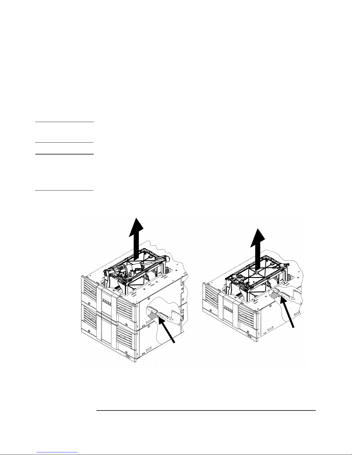
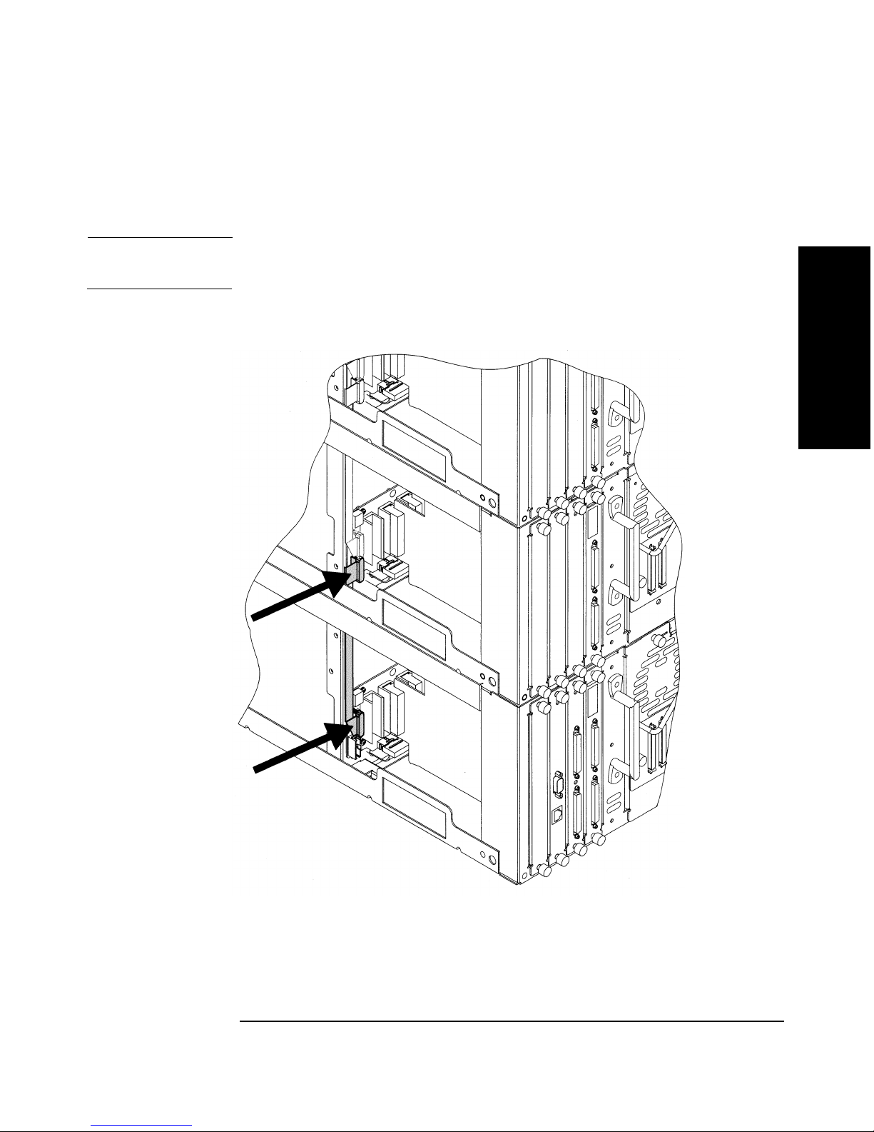
3. Remove the interconnect cable that connects the lowest library
module with the module directly above it.
CAUTION To prevent damage to the library, completely remove the interconnect
cable between the bottom two modules.
Figure 2-18 Removing the Interconnect Cable
Replacing Library Parts
Chapter 2 2-41
Page 70

Removing and Replacing Major Library Components
Removing and Replacing the Transport Assembly (for Model 12/140 only)
4. From the back of the library, remove the shipping brackets that are
next to the bottom library module by removing the 10-32 T-25 screws
(two on each side).
Figure 2-19 Removing the Shipping Brackets
Chapter 22-42
Page 71

Removing and Replacing Major Library Components
Removing and Replacing the Transport Assembly (for Model 12/140 only)
5. Go to the front of the library, and pull out the doors on the lowest
module.
6. Behind the doors, loosen the two 10-32 T-25 screws that secure the
retainer bracket on the module to the cabinet.
Figure 2-20 Removing the Retainer Brackets
Replacing Library Parts
7. Turn the service handle counter-clockwise to lower the bottom
module. Lower the module all the way down to ensure there is enough
clearance for the vertical lift assembly.
8. Gently pull out the bottom library module.
Chapter 2 2-43
Page 72

Removing and Replacing Major Library Components
Removing and Replacing the Transport Assembly (for Model 12/140 only)
Removing the Transport Assembly
1. Using the finger-holes in the top of the transport assembly, lift the
assembly up and out of the library (Figure 2-21).
CAUTION Use care to protect the flat, umbilical cable attached to the bottom of the
transport assembly.
Figure 2-21 Removing the Transport Assembly
2. Place the transport assembly next to the library and disconnect the
umbilical cable by pulling the tabs outward (Figure 2-21).
3. If you are only replacing the transport assembly and not the vertical
lift motor, remove the motor to install on the replacement transport
assembly. See “Replacing the Vertical Lift Assembly” on page 2-48 for
more information.
NOTE You need to remove the guide blocks on the replacement transport
assembly to install the vertical lift assembly. See Figure 2-14 on page 2-
33.
Chapter 22-44
Page 73

Removing and Replacing Major Library Components
Removing and Replacing the Transport Assembly (for Model 12/140 only)
Replacing the Transport Assembly
Install the replacement transport assembly by following these steps:
1. Connect the umbilical cable to the bottom of the library chassis.
CAUTION Use care to protect the flat, umbilical cable attached to the bottom of the
transport assembly. Do not bend the pins.
a. Align the gears on the transport assembly with the gear rails on
the library (Figure 2-22).
b. Check the gear teeth position to ensure they are aligned with the
gear rails and that the gear rails are level with each other (Figure
2-22).
CAUTION The alignment of the gears with the gear rails is critical. The library will
test to ensure alignment.
Figure 2-22 Transport Assembly Position
Replacing Library Parts
A Gears incorrectly aligned 1 Gears
B Gear correctly aligned 2 Gear rails (racks)
Chapter 2 2-45
3 Check points to ensure
alignment
Page 74

Removing and Replacing Major Library Components
Removing and Replacing the Transport Assembly (for Model 12/140 only)
2. When the transport assembly is level with the top of the library,
lower it to the bottom of the library.
Re-installing the Bottom Module
1. After servicing the product, gently push the bottom library module
into the cabinet until it aligns with the module above it.
2. Turn the service handle clockwise to begin raising the module while
you are holding the module flush against the cabinet.
3. When the bottom module is one inch from the module above it, check
to ensure the guide pins are aligned with the holes on the upper
module.
CAUTION To prevent damaging the library, ensure the modules are aligned with the
guide pins.
4. After ensuring the modules are aligned, continue turning the service
handle clockwise until the modules are engaged and you feel
resistance.
Figure 2-23 Checking the Module Alignment
Chapter 22-46
Page 75

Removing and Replacing Major Library Components
Removing and Replacing the Transport Assembly (for Model 12/140 only)
Reassembling the Library
After replacing the transport assembling and reconnecting the modules,
complete the following:
1. Reattach the interconnect cable between the bottom two modules (see
Figure 2-18 on page 2-41).
2. Replace the screws that secure the retainer brackets on the bottom
module to the cabinet (see Figure 2-20 on page 2-43).
3. Replace the library side panels on the bottom two modules (see
Figure 2-17 on page 2-39).
4. Replace the side panels on the cabinet (see Figure 2-16 on page 2-38).
5. Replace the shipping brackets (see Figure 2-19 on page 2-42).
6. Replace the external cables and power cord on the bottom module.
NOTE If the new transport assembly has a different version of firmware than the
rest of the library, the library could go into a partial availability state due
to a firmware mismatch. When this occurs, the front panel will display
Partly Available, and the LED bar beneath the front panel display will be
solid amber. This is not an indication of a failure, but indicates that you
need to download new library firmware.
Replacing Library Parts
Chapter 2 2-47
Page 76

Removing and Replacing Major Library Components
Removing and Replacing the Vertical Lift Assembly for Models 4/40, 6/60, and 12/140
Removing and Replacing the Vertical Lift
Assembly for Models 4/40, 6/60, and 12/140
Level of Difficulty: [5} Difficult
Removing the Vertical Lift Assembly
NOTE The vertical lift assembly, although attached to the transport assembly,
is a separate FRU. The vertical lift assembly is only used in multi-level
libraries.
You must remove the transport assembly to access the vertical lift
assembly. See page 2-28 or page 2-36 for instructions on removing it from
the library.
Use the following steps to remove the vertical lift assembly:
1. Remove the transport assembly by following the steps on page 2-28 or
page 2-36.
2. Once you have removed the transport assembly, disconnect the motor
power cable from the lift circuit board (Figure 2-24 on page 2-49).
3. Disconnect the vertical lift cable by pressing the release tab and
pulling the connector outward.
4. Remove the screws that secure the lift assembly and the lift circuit
board to the top of the transport assembly. Remove both assemblies
(Figure 2-24 on page 2-49).
Replacing the Vertical Lift Assembly
1. Align the lift circuit board with the screw holes, and insert two 4-20
T-10 screws. Tighten the screws securely, but do not over-tighten.
2. Align the screw holes in the lift assembly to the top of the transport
assembly. Install five 6-19 x .5 screws, tightening the motor mount
screws last.
3. Reconnect the vertical lift cable.
4. Reconnect the motor power cable.
Chapter 22-48
Page 77

Removing and Replacing the Vertical Lift Assembly for Models 4/40, 6/60, and 12/140
Figure 2-24 Vertical Lift Assembly
Removing and Replacing Major Library Components
Replacing Library Parts
1 Five 6-19 x .5 T-15 screws
2 Two 4-20 T-10 screws
3 Motor power cable
4 Vertical lift cable connector
Chapter 2 2-49
Page 78

Removing and Replacing Major Library Components
Removing and Replacing the Motherboard
Removing and Replacing the Motherboard
Level of Difficulty: [4] Moderate to Difficult
Removing the motherboard requires a series of disassembly steps to
access the board. Review the entire removal process before beginning
this procedure.
Removing the Motherboard
Use the following steps to remove the motherboard:
1. Power off the library and disconnect the power cords.
CAUTION This library contains very sensitive electronic components. It is important
to follow the proper procedures for preventing electrostatic discharge
(ESD). Use wrist-grounding straps and anti-static mats when removing
and replacing the major assemblies.
Failure to follow proper procedures could damage the circuitry.
2. Record the location of all cables and cords to replace at the end of this
procedure.
3. Disconnect all external cables from the back of the library.
4. Remove the following:
• Power supply (page 2-59)
• Drive modules (page 2-21)
• Cards (page 2-18)
• Vacant card slot and drive covers
Chapter 22-50
Page 79

Removing and Replacing Major Library Components
Removing and Replacing the Motherboard
5. Disconnect all cables on the back of the motherboard (Figure 2-25).
Cable locations may vary, depending on the library model.
Figure 2-25 Motherboard Cable Connections
Replacing Library Parts
1 Display cable connector
2 Interconnect cable (on multi-level libraries)
3 Fan cable
4 Umbilical cable (on lowest level)
5 Door lock power cable
6 Guide pins
Chapter 2 2-51
Page 80

Removing and Replacing Major Library Components
Removing and Replacing the Motherboard
6. Remove ten 4-40 x .625 10-T screws from the motherboard. See
Figure 2-26 for the screw locations.
TIP Use a 8 inch x 1/4 inch magnetic extension to remove these screws.
Figure 2-26 Screw Locations on the Motherboard
1 Four 4-40 x .625 10-T screws in the card bay area
2 Three 4-40 x .625 10-T screws in the drive bay area
3 Three 4-40 x .625 10-T screws in the power supply bay
Chapter 22-52
Page 81

Removing and Replacing Major Library Components
Removing and Replacing the Motherboard
7. Loosen the thumbscrew on the sheet-metal cover nearest the left
drive bay and rotate the cover clockwise (Figure 2-27).
Figure 2-27 Rotating the Sheet-Metal Cover
Replacing Library Parts
8. If the library is rackmounted, use the following steps to slide it
forward in the rack (for models 2/20, 4/40, and 6/60 only):
CAUTION For library models 12/140, do not push the library out of the cabinet.
Instead, remove the side panels by using the procedure in “Accessing the
Side Panels for Service” on page 2-36.
a. Lower the leveler feet, and fully extend the anti-tip foot at the
front of the rack.
WARNING Failure to extend the anti-tip device could result in personal
injury or damage to the tape autoloader if the rack tips over.
Chapter 2 2-53
Page 82

Removing and Replacing Major Library Components
Removing and Replacing the Motherboard
AVERTISSEMENT Si vous ne déployez pas le dispositif antibasculant, le rack risque de
se renverser et de provoquer des blessures ou d’endommager
l’autochargeur de bande.
ACHTUNG Wird die Abstützvorrichtung nicht herausgezogen, kann dies zu
Beschädigungen des Autoloaders führen, sollte der
Einschubschrank umkippen.
AVVISO Se non si estende il dispositivo anti-inclinazione, si potrebbero
provocare lesioni personali o danni all’autoloader, in caso di
rovesciamento dello scaffale.
ADVERTENCIA En caso de no abrir el dispositivo estabilizador, existe el peligro de que
se produzcan lesiones personales o daños al cargador automático de
cintas si se vuelca el bastidor.
b. Pull out the front doors and unscrew the screws that secure the
library to the rack.
c. Push the library out until it hits the stop bracket (approximately
60% out of the rack).
Chapter 22-54
Page 83

9. Remove the #4 - 40 x. 312 T-8 screws from the library’s right-side
panel, shown in Figure 2-28 (right, viewed from the front of the
library), and slide the panels off the library. Remove the 12/140 side
panels by following the steps on page 2-36.
Figure 2-28 Removing Two Side Panels
Removing and Replacing Major Library Components
Removing and Replacing the Motherboard
Replacing Library Parts
Side Panels for Model 2/20, 4/40, and 6/60 Side Panels for Model 12/140
Chapter 2 2-55
Page 84

Removing and Replacing Major Library Components
Removing and Replacing the Motherboard
10.Open the front door on the right side for more room. Disconnect the
magazine harness cable from the front of the motherboard by pushing
the ejection tabs on the connector outward (Figure 2-29).
Figure 2-29 Magazine Lock Harness Cable Connection
Chapter 22-56
Page 85

Removing and Replacing Major Library Components
Removing and Replacing the Motherboard
11.Carefully remove the motherboard from the side of the library (Figure
2-30).
TIP If the library is rackmounted, remove the right side panel of the rack to
access the motherboard.
Figure 2-30 Removing the Motherboard
Replacing Library Parts
Chapter 2 2-57
Page 86

Removing and Replacing Major Library Components
Removing and Replacing the Motherboard
Replacing the Motherboard
1. Insert the new motherboard into the side of the library. Align it by
using the guide pins near the drive bays (Figure 2-25 on page 2-51).
2. Replace the ten screws that secure the motherboard to the library
chassis (Figure 2-26 on page 2-52).
3. Connect all cables to the motherboard (Figure 2-25 on page 2-51 and
Figure 2-29 on page 2-56).
4. Replace the library’s side panels, and tighten the screws (Figure 2-28
on page 2-55).
5. Push the library fully into the rack (if needed), and secure it to the
rack.
6. Rotate the sheet-metal cover back into place, and tighten the
thumbscrew.
7. Replace the library cards, drives, vacant slot covers, and power
supply.
8. Replace all external cables and cords.
9. Connect the power cord(s) into a grounded power outlet and power on
the library.
Chapter 22-58
Page 87

Removing and Replacing Major Library Components
Removing and Replacing the Power Supply
Removing and Replacing the Power Supply
Level of Difficulty: [1] Easy
A failing power supply on Model 2/20 disables the library. A failing
power supply on upper library levels results in a partial availability
state. When the library is in a partial availability state, it is still
functional, but is not in optimum configuration. When this occurs, the
front panel will display
beneath the front panel display will be solid amber until the condition is
resolved. (Refer to your user’s guide for more information on the partial
availability state.)
Partially Available, and the illuminated LED
Removing the Power Supply
1. Power off the library.
2. Disconnect the power cord from the back of the power supply.
3. Loosen the thumbscrews at the top and bottom of the power supply. If
the thumbscrews are too tight to loosen by hand, loosen them with a
screwdriver.
4. Remove the stop bracket (for Model 2/20 only).
Replacing Library Parts
Figure 2-31 Removing the Stop Bracket for Model 2/20
Chapter 2 2-59
Page 88

Removing and Replacing Major Library Components
Removing and Replacing the Power Supply
5. Remove the power supply with one hand and pull outward. Support
the bottom of the power supply to avoid dropping the module.
Replacing the Power Supply
1. Grasp the power supply handle with one hand while supporting the
bottom with your other hand. Align the power supply with the guide
notch at the top of the power supply bay.
2. Fully insert the power supply into the library.
3. Replace the stop bracket (for Model 2/20 only).
4. Tighten the two thumbscrews.
5. Connect the power cord to the power supply.
Chapter 22-60
Page 89

Removing and Replacing Major Library Components
Removing and Replacing the Redundant Power Supply
Removing and Replacing the Redundant
Power Supply
Level of Difficulty: [1] Easy
Replacing the Redundant Power Supply Module
CAUTION When replacing the entire power supply module, note that the library
does not have redundant power backup until the new module is installed.
See page 2-63 for the procedure for replacing individual power supply
units.
1. Disconnect the power cords from the library. Contact the system
administrator to ensure there is no activity on the SCSI bus.
2. If you are replacing a module on the top level of the library, ensure
the stop bracket is removed from the top of the library. See Figure
2-11 on page 2-30.
3. Remove the power supply to be replaced by loosening the two 6-32 x
.25 T15 screws and pulling the module straight out.
4. Install the replacement power supply module by aligning the bottom
of the module with the bottom of the power supply bay.
Replacing Library Parts
5. Fully insert the power supply module into the back of the library.
6. Tighten the two screws.
7. The replacement FRU comes with the entire redundant power supply
module and one individual unit (see Figure 2-32 on page 2-62). If you
need to install an additional unit, install one of the units from the
original power supply.
8. Reconnect the power cord to the power supply.
Chapter 2 2-61
Page 90

Removing and Replacing Major Library Components
Removing and Replacing the Redundant Power Supply
Figure 2-32 Replacing the Redundant Power Supply Module
CAUTION Do not move the covered power switch located at the bottom of the
module. By default, power is always kept on to ensure redundant backup.
NOTE The redundant power supply module FRU comes with the entire module
and one power supply unit. If you need an individual unit and not the
entire module, then use the one that comes with the replacement module.
Chapter 22-62
Page 91

Removing and Replacing Major Library Components
Removing and Replacing the Redundant Power Supply
Replacing Individual Redundant Power Supply Units
Level of Difficulty: [1] Easy
To replace individual power supply units:
1. Push the tab on the power supply unit to the left.
2. Remove the supply using the handle on the back of the unit and
pulling outward. Support the bottom of the power supply to avoid
dropping or damaging it.
WARNING Avoid touching the top surface of the power supply unit since it
may be hot.
Replacing Library Parts
Chapter 2 2-63
Page 92

Removing and Replacing Major Library Components
Removing and Replacing the Redundant Power Supply
3. Install the new power supply by sliding the replacement unit into the
vacant slot until it “clicks” into place.
Figure 2-33 Replacing Individual Power Supply Units
Chapter 22-64
Page 93

Removing and Replacing Major Library Components
Removing and Replacing the Power Distribution Unit (for Model 12/140 only)
Removing and Replacing the Power
Distribution Unit (for Model 12/140 only)
Level of Difficulty: [3] Moderate
The power distribution unit is the black power strip that is located at the
bottom and at the back of the cabinet.
To replace this part (see Figure 2-34 on page 2-66):
1. Power off the library.
2. Unplug all power cords from the power distribution outlet.
3. Disconnect the ground wire by removing the 10-32 T-25 screw that
secures the wire between the power distribution unit and the library
cabinet.
4. Unplug the power distribution unit from the grounded wall outlet.
5. Remove the two 10-32 T25 screws and nuts from each side of the unit.
These screws secure the unit to the back of the cabinet.
Replacing Library Parts
Chapter 2 2-65
Page 94

Removing and Replacing Major Library Components
Removing and Replacing the Power Distribution Unit (for Model 12/140 only)
Figure 2-34 Removing the Power Distribution Unit
Chapter 22-66
Page 95

Removing and Replacing Major Library Components
Removing and Replacing the Front Panel Display
Removing and Replacing the Front Panel
Display
Level of Difficulty: [3] Moderate
Removing the Front Panel Display
CAUTION This library contains very sensitive electrical components. Follow the
proper procedures for preventing electrostatic discharge (ESD). Use
wrist-grounding straps and anti-static mats when removing and
replacing cards and assemblies. Failure to follow proper procedures could
damage the circuitry.
1. Power off the library.
2. Remove the display cover and chin plate underneath the display on
the existing library module. The 6-32 screw locations are indicated in
Figure 2-35 on page 2-67.
3. Remove the display cover by lifting it upward and away from the
library.
Figure 2-35 Removing the Chin Plate and Front Cover
Replacing Library Parts
Chapter 2 2-67
Page 96

Removing and Replacing Major Library Components
Removing and Replacing the Front Panel Display
4. Remove the two 6-32 screws that connect the display to the chassis
(Figure 2-36).
Figure 2-36 Removing the Front Panel Display
5. Remove the front panel display by sliding it upward, then gently
lifting it away from the front of the library.
6. Disconnect the cable from the back of the display by grasping the
sides of the connector and pulling outward. Place the front panel in
an ESD-protected area.
Replacing the Front Panel Display
1. Connect the display cable to the front panel connector. The display
attaches to two tabs on the side of the display opening. Attach the
display on the tabs and slide it down.
For multi-level libraries, ensure the display cable is not obstructing
the vertical lift transport assembly by attaching it to the inside edge of
the library chassis.
Chapter 22-68
Page 97

Removing and Replacing Major Library Components
Removing and Replacing the Front Panel Display
2. Install the two long 6-32 T-10 screws that are next to the soft keys to
secure the display to the chassis (see Figure 2-37).
Figure 2-37 Connecting the Front Panel
3. Re-install the display cover by easing the top of the cover underneath
the forehead and sliding it down (see Figure 2-35 on page 2-67).
Tighten the two 6-32 phillips head screws to secure the display cover
in place.
Replacing Library Parts
4. Install the viewing window, and tighten the two phillips head screws
to secure the window in place.
5. Install the four screws that connect each chin plate (see Figure 2-35
on page 2-67 for all screw locations).
Chapter 2 2-69
Page 98

Removing and Replacing Major Library Components
Removing and Replacing a Cosmetic Door
Removing and Replacing a Cosmetic Door
Removing a Cosmetic Door Face
Level of Difficulty: [2] Easy to Moderate
1. Pull the front door outward. Use the front panel display or key, if
necessary, to unlock the door.
2. Remove the front magazine by lifting the handle on the top of the
magazine and pulling upward.
3. Twist the release tab on the back of the cosmetic door and
simultaneously pull upward on the sheet-metal tab to release (see
Figure 2-38 on page 2-71).
CAUTION To avoid breaking the tab, do not use excessive force.
Replacing a Cosmetic Door
1. Insert the cosmetic door’s connecting hooks through the holes in the
front of the door.
2. Holding the cosmetic door in place, align the holes in the sheet-metal
with the holes in the door front.
3. Push the sheet-metal tab downward so that the sheet-metal plate
clicks into place beneath the plastic tab.
4. Replace the magazine, and close the door.
Chapter 22-70
Page 99

Figure 2-38 Removing Front Door Face
Removing and Replacing Major Library Components
Removing and Replacing a Cosmetic Door
Replacing Library Parts
1Release tab
2 Sheet-metal tab
3 Cosmetic door connecting hooks
Chapter 2 2-71
Page 100

Removing and Replacing Major Library Components
Removing and Replacing a Cosmetic Door
Chapter 22-72
 Loading...