

Page 1
Illustrated Parts & Service Map
HP 100B All-In One PC
© 2011, 2012 Hewlett-Packard Development Company, L.P. The information
contained herein is subject to change without notice. HP shall not be liable for
technical or editorial errors or omissions contained herein. Intel, Pentium, Intel
Inside, and the Intel logo are trademarks or registered trademarks of the Intel Cor-
poration and its subsidiaries in the U. S. and other countries.
Document Number 640046-002. 2nd Edition June 2012.
Spare Parts
Key Specifications
Processor Type AMD single-core and dual-core, soldered to system board
RAM Type DDR3-SDRAM DIMMs, PC2-10600 (1333 MHz) non-ECC
Maximum RAM 4 GB (2 slots)
Power 90W PFC/90W HV External AC power adapter
Display 20-inch, non-glare, 1600x900 CCFL LCD
LAN (Wired) 10/100/1000 baseT
Wireless 802.11 b/g/n Wireless LAN (optional)
Graphics ATI Radeon UMA Graphics
Drive Support • (1) optical drive (DVD±RW SuperMulti DL)
I/O Interfaces (6) USB ports - 2 side, 4 rear, (1) Headphone jack,
Operating Systems • Windows 7 Professional
(Radeon HD 6300, DX11, UVD 3.0)
• (1) hard drive (750 GB, 500 GB, 250 GB)
(1) Line-out, (1) Microphone-in jack
• Red Flag Linux
• FreeDOS
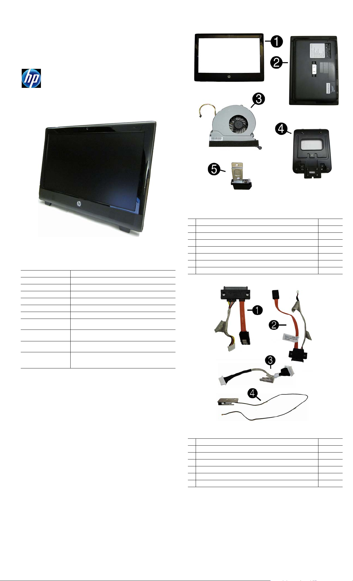
System Unit
1 Front bezel 646780-001
2 Rear cover assembly 646781-001
3 Fan assembly 646798-001
4 Stand assembly 646783-001
5 Foot, right 646784-001
* Foot, left 646785-001
* Display panel, 20-inch, Samsung/CMI 646794-001
* Display panel, 20-inch, LG 646795-001
* Not shown
Cables
1 Hard drive cable 646789-001
2 Optical drive cable 646790-001
3 Power button board cable 646782-001
4 WLAN antenna 646806-001
* Webcam cable 646786-001
* LVDS cable 646787-001
* Inverter cable 646788-001
*Not shown
HP 100B AIO Illustrated Parts & Service Map 640046-002 page 1
Page 2

Drives (not illustrated)
1 8X DVD±RW SuperMulti DL Drive with LightScribe with bezel 646803-001
* 8X DVD±RW SuperMulti DL Drive with LightScribe without bezel 619238-001
2 750 GB hard drive 632938-001
2 500 GB hard drive 621421-001
2 250 GB hard drive 621419-001
3 Optical drive holder 646805-001
4 Optical drive bezel 646804-001
Miscellaneous Parts
1 Heat sink (thermal module) 646799-001
2 Speaker, right 646792-001
2 Speaker, left 646793-001
* Hard drive grommets (screws) 646791-001
* External AC adapter, 90W 646779-001
* Power cord for use in the United States 246959-001
* Power cord for use in Brazil 490371-202
* Power cord for use in Argentina 403811-201
* Power cord for use in Italy 246959-061
* Mouse, USB, optical, Portia 596410-001
* Screw Kit, includes
- PM 2.0x3.0, quantity 2
- PM 2.0x5.0, quantity 4
- PM 3.0x8.0, quantity 4
- T8M 2.0x5.0 quantity 2
- PM 2.5x7.0, quantity 48
- T15M 3.0x4.0, quantity 7
- T15M 4.0x5.0, quantity 8
- #6/32x8.5, quantity 4
*Not shown
Keyboards (not illustrated)
USB keyboard for use in the United States 537924-001
USB keyboard for use in Latin America 537924-161
USB keyboard for use in Brazil 537924-201
647523-001
Standard and Optional Boards
1 System board, AMD, dual core (includes thermal material) 644692-001
2 Inverter for use with Samsung/CMI display panels 646796-001
* Inverter for use with LG display panels 646797-001
3 WLAN module (802.11a/b/g/n) 634906-001
4 Power switch board assembly 649230-001
Memory modules (PC3-10600)
*1 GB
*2 GB
*4 GB
* Not shown
647448-001
646800-001
646801-001
HP 100B AIO Illustrated Parts & Service Map 640046-002 page 2
Page 3

System Board Computer Setup.
Heading Option/Description
File System Information - Lists the following main system specifications:
• Product name
• SKU number (some models)
• Processor type/speed/stepping/
cache size
About - Displays copyright notice.
Set Time and Date - Allows you to set system time and date.
Apply Defaults and Exit - Applies the selected default settings and clears any
established passwords.
Ignore Changes and Exit - Exits setup without applying or saving any changes.
Save Changes and Exit - Saves changes to system configuration or default set-
tings and exits Computer Setup.
System Board Connectors and Jumpers (component location may vary)
WEB CAM Webcam connector USB_CON USB connectors (4)
POWER Power button board connec-
DIMM3 Memory socket 2 HDD_CON Hard drive data connector
DIMM1 Memory socket 1 ODD_CON Optical drive data connector
USB_CON USB connectors (2) ODD
BAT RTC battery socket
MIC Microphone connector S/W System password header
HEAD-
PHONE
LINE _OUT
SPK_L Speaker jack - left PCIE WLAN module slot
SPK_R Speaker jack - right
LAN_CON RJ-45 /LAN connector
Common POST Error Messages
Screen Message Probable Cause Recommended Action
101-Option ROM Error System ROM or expansion
103-System Board
Failure
164-Memory Size Error Memory amount has
164-Memory Size Error Incorrect memory configu-
201-Memory Size Error RSM failure 1. Ensure memory modules are
214-DIMM Configuration Warning
301-, 304-Keyboard error Keyboard failure. 1. Reconnect keyboard with
511-Display Adapter Failure
1801-Microcode Patch
Error
1801-Microcode Patch
Error
tor
Headphone jack INVERTER Inverter board connector
Headphone jack
board option ROM checksum.
DMA or timers 1. Clear CMOS memory.
changed since the last boot
(memory added or
removed).
ration
Populated DIMM configuration is not optimized
CPU Fan no Detected. 1. Reseat CPU fan.
Processor not supported by
ROM BIOS.
Processor is not supported
by ROM BIOS.
HDD
POWER
POWER
LCD_CON
FAN
SW1
Hard drive power connector
Optical drive power connector
Display connector
System fan connector
CMOS password header
1. Verify ROM, reflash if required
2. Remove any recently added
cards to see if problem remains.
3. Clear CMOS. If message
disappears, may be problem
with card.
4. Replace system board
2. Remove expansion boards.
3. Replace system board.
Press the F1 key to save the memory changes.
1. Run Setup (F10).
2. Make sure memory module(s)
installed properly.
3. If third-party memory added,
test using HP-only memory.
1. Verify proper module type.
correctly installed.
2. Verify proper module type.
3. Remove and replace identified
faulty memory module(s).
4. If error persists after replacing
modules, replace system board.
Rearrange the DIMMs so that
each channel has the same amount
of memory.
system turned off.
2. Check keyboard connection or
keys.
3. Check connector for bent or
missing pins.
4. Replace keyboard.
5. If 304, possible system board
problem.
2. Reseat fan cable.
3. Replace CPU fan.
1. Upgrade BIOS to proper
version.
2. Change the processor.
1. Upgrade ROM proper version.
2. Change the processor.
Storage Device Configuration - Lists all installed BIOS-controlled storage devices.
Security Setup Password - Allows you to set and enable setup (Administrator) password.
Power Hardware Power Management-Lets you enable/disable SATA bus power man-
Advanced Power-On Options - Allows you to set:
• Hard Disk - size, model, firmware, serial number, connector color , SMART,
emulation type
• CD-ROM - model, firmware, serial number.
• SATA Emulation - AHCI, IDE
DPS Self-Test - Lets you execute self-tests on DPS-capable ATA hard drives.
Boot Order - Allows you to specify boot order or order of attached hard drives.
• Shortcut to Temporarily Override Boot Order
Power-On Password - Allows you to set and enable power-on password.
Device Security (some models) - Enables/disables audio, network controllers,
embedded security devices., SATA0-1, system audio, network controllers.
USB Security - Allows you to enable/disable groups of or individual USB ports.
Front USB Ports 11,13, Rear USB Ports 0,1,4,9. Accessory ports 3, 12.
Slot Security - Allows you to enable/disable the mini card slot.
Network Service Boot - Enables/disables boot from OS on a network server.
System IDs - Shows product name, chassis serial number/ UUID, SKU number,
family name, feature.; Allows you to set keyboard locale setting.
DriveLock Security-Lets you assign/modify hard drive p/w for added security.
System Security (some models) - Allows you to enable/disable:
• Data Execution Prevention
• Protected Audio Video Path (PAVP) (some models)
• Virtualization Technology(some models)
• Virtualization Technology Directed I/O (some models)
• Trusted Execution Technology I/O
• Embedded Security Device Support
• OS management of Embedded Security Device (some models)
• Button Retask Password Protection
• Power Button
• Consumer IR Power Button
• Optical Drive Eject Button
agement and S5 maximum power savings.
Thermal - Allows you to control minimum permitted fan idle speed.
• POST messages - Enable/disable
• After Power Loss - Off/on/previous state
• POST Delay - None, 5, 10, 15, or 20 seconds
BIOS Power-On - Allows you to set the computer to turn on at a preset time.
Bus Options (some models) - Allows you to enable/disable PCI SERR# Gener-
ation and PCI VGA palette snooping.
Device Options - Allows you to set:
• Num Lock State at Power-On (on/off)
• Multi-Processor (enable/disable)
• Internal Speaker (some models)
• NIC Option ROM Download (PXE, Disable, iSCSI
Management Devices - Only displayed in the Advanced Menu when the BIOS
detects multiple management options. This option is for installed NIC cards that
support ASF or DASH. Use the Management Devices menu to select if the
BIOS management operations will be through the embedded solution or one of
the installed NIC cards.
Management Operations - Allows you to set:
• MEBx Setup Prompt (enable/disable)
• Unprovision AMT on next boot
• SOL Terminal Emulation Mode
• SOL Local Keyboard (enable/disable)
• Memory size/speed/ no. channels
• Integrated MAC Address
• System BIOS
• Chassis serial number
HP 100B AIO Illustrated Parts & Service Map 640046-002 page 3
 Loading...