

Page 1
r/i~
.:~
HEWLETT
PACKARD
HP
20-Slot
Installation
1000 A990
System/Computer
and
Service
Manual
Page 2
rl"-'
.:~
HEWLETT
PACKARD
H P 1
000
A990
20-Slot
System/Computer
Installation and Service Manual
Manual Part No. 02959-90002
E0292
Measurement & Control Systems Dlvison
11000 Wolfe Road
Cupertino, CA 95014
Printed in U.S.A. February 1992
First Edition
Page 3
NOTICE
The information contained
HEWLETT-PACKARD
INCLUDING, BUT NOT
FITNESS
FOR A PARTICULAR
contained herein or for
MAKES
LIMITED
incidental or consequential damages in connection with the furnishing,
performance, or use of this
Hewlett-Packard
ment that is not furnished
assumes no responsibility for the use or reliability of its software on equip-
by
This document contains proprietary information which is protected
in
this document is subject to change without notice.
NO
WARRANTY
TO,
THE
OF
ANY
IMPLIED
KIND
WITH
WARRANTIES
REGARD
OF
PURPOSE. Hewlett-Packard shall not be liable for errors
material.
Hewlett-Packard.
by
copyright. All rights are
reserved. No part of this document may be photocopied, reproduced, or
language without the prior written consent of Hewlett-Packard Company.
RESTRICTED
Use,
duplication, or disclosure
subparagraph
DFARs
RIGHTS
(c)
(1)
252.227.7013
LEGEND
by
(ii) of the Rights
the Government is subject to restrictions as set forth
in
Copyright © 1992
Technical Data and Computer Software clause at
by
HEWLETT-PACKARD
2
COMPANY
TO
THE
MATERIAL,
MERCHANTABILITY AND
translated to another
in
Page 4
Safety and Regulatory Information
For your protection, this product has been tested to various national and international
regulations and standards. The scope of this regulatory testing includes electrical/mechanical
safety, radio frequency interference, ergonomics, acoustics, and hazardous materials. Where
required, approvals obtained from third-party test agencies are shown on the product label.
In addition, various regulatory bodies require some of the information under the following
headings.
USA (Radio Frequency Interference)
The United States Federal Communications Commission (in 47CFR Subpart J, of Part
15)
has specified that the following notice be brought to the attention of the users of this product:
Warning
o
This equipment generates, uses, and can radiate radio frequency
if
energy, and
tions
manual, may cause interference to radio communications. It
not installed and used in accordance with the instruc-
has been tested for compliance with the limits for Class A computing
devices pursuant to Subpart J
designed
ence. Operation
to
provide reasonable protection against such interfer-
of
this equipment in a residential area is likely
of
Part
15
of
FCC
Rules, which are
to
cause interference, in which case the user, at his own expense, will
be required to take whatever measures may be required
to
correct
the interference.
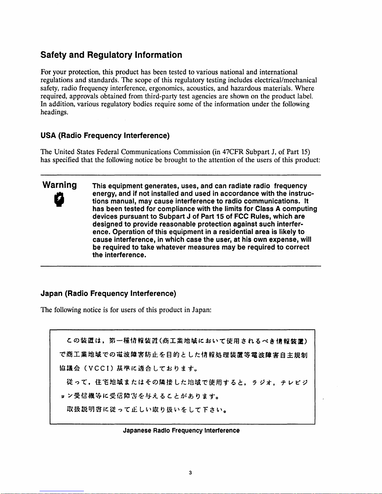
Japan (Radio Frequency Interference)
The following notice
is
for users of this product in Japan:
c::.
0)~11l
~~I~~~~~~
~
11.
~
Vf
~
:r
/
~Fa.~
1&
t&
(V
1:",
m
DJ)
'i,
m
-fitn
•••
eel)
it'={;
m
~ ~
itt!
~ i
Ie
~1~·1tr.tr;y
Ie
VE
"?
-r
Japanese Radio Frequency Interference
fa
~
in (ttli
I~!tI.!~
W~~§~~L~m~M~~
Ie
~
~
L L
jo
J)
i T u
t.:
,;t
-'C
~
~
tf
L
t.:
It!l
~
~4~
1f.
L
-5
c.
~'1&
~
t&
C
tJ~ ~ ~
~
,~
L L F
3
Ie
io~'
~
(i
,Efj
i:
j-o
~
-C
fl!ffl
T
7.>
~'o
~ n ~ ~ ~
•••
~,
~.~m~m~
7::.i
*,
Uf
fi~
T v
t:"
iI)
~
Page 5

United Kingdom (Telecom Declaration)
This product is approved under approval number
public telecommunication systems within the United Kingdom.
NS/G/1234/J/1()()()()3
for indirect connection to
Europe (Data Communications)
The remote support interface conforms to
connection to a public telecommunications network, use only a modem complying with local
regulations.
CCITI
Recommendations
V.24
and
V.28.
For
Germany (Acoustics)
Laermangabe (Schalldruckpegel
nach
DIN
45635,
Acoustic Noise (A-weighted Sound Pressure Level
normal operation to
Teil
19:
ISO
LpA
7779:
LpA)
<
70
LpA
gemessen am fiktiver Arbeitsplatz bei normalem Betrieb
dB
LpA)
measured at the bystander position,
<
70
dB
4
Page 6
Safety Considerations
GENERAL - This product and related documentation must be reviewed for familiarization with
safety markings and instructions before operation.
SAFETY SYMBOLS
Instruction manual symbol: the product will be marked with this symbol when it is
necessary for the user to refer to the instruction manual in order to protect the
product against damage.
Indicates hazardous voltages.
Indicates earth (ground) terminal (sometimes used
common connected to grounded chassis).
Caution
I
Warning
G
in
manual
Explanation
The CAUTION sign denotes a hazard.
procedure, practice, or the like, which, if not correctly performed or
hered to, could result in damage to or destruction of part or all of the
product. Do not proceed beyond a
fully
conditions are
understood and met.
Explanation
The WARNING sign denotes a hazard. It calls attention
dure, practice,
hered to, could result in injury.
sign until the indicated conditions are fully understood and met.
or
the like, which,
of
Caution
It
calls attention to an operating
CAUTION sign until the indicated
of
Warning
if
not correctly performed
Do
not proceed beyond a WARNING
to
indicate circuit
to
a proce-
or
ad-
ad-
5/6
Page 7

Page 8

Printing History
The Printing History
cally, update packages are distributed which contain replacement pages to
cluding an updated
Each reprinting
Thus, the reprinted
update information. New editions
To
determine what manual edition and update is compatible with your current software revision code, refer to
the Manual Numbering File or the Computer User's Documentation Index. (The Manual Numbering File is
included with your software.
First Edition
below
of
this manual will incorporate all past updates; however, no
copy
identifies the edition
copy
of
this printing history page. Also, the update
will
be
identical
It
consists of an "M" followed
..................
of
this manual and any updates that are included. Periodi-
in
content to prior printings of the same edition with its user-inserted
of
this manual will contain new information, as well as all updates.
by
a five digit product number.)
Feb 1992
..................................
be
merged into the manual, in-
may
contain write-in instructions.
new
information will
be
.
added.
7/8
Page 9

Page 10

Preface
The
HP
1000
A990
20-S10t System/Computer Installation and Service Manual, part number
02959-90002,
A990 Computer and the
service engineers.
Chapter 1 - Introduction
Includes environmental and electrical specifications plus site preparation, unpacking, and loss or
damage claims procedure information.
Chapter 2 - Installation
Gives configuration information and describes the procedures for installing the A990 computer.
Chapter 3 - Service
Describes maintenance and troubleshooting requirements and procedures, power supply checks,
power-on self-tests, and definitions of LED indicators. Also describes procedures for removing
and replacing assemblies and reconfiguring the power supply.
describes the procedures for configuring, installing, and servicing, the
HP
2999A A990 System. This manual is written for systems and field
HP
2959A
Chapter 4 - Replaceable Parts
Lists and illustrates replaceable parts for the A990 computer.
9/10
Page 11

Page 12
Chapter 1
Introduction
Table of Contents
Site Preparation
Environmental Considerations
Power
Cooling Requirements. . . . . . . . . . . . . . . . . . . . . . . . . . . . . . . . . . . . . . . . . . . . . . . . . . . . . . .
Mounting Considerations . . . . . . . . . . . . . . . . . . . . . . . . . . . . . . . . . . . . . . . . . . . . . . . . . . . .
Unpacking and Inspecting
Claims Procedure
Physical Inventory
.....
"..........................................................
Requirements.
....
" . . . . . . . . . . . . . . . . . . . . . . . . . . . . . . . . . . . . . . . . . . . . . . . . . . . . . . . . . .
...
"..........................................................
...............................................
. . . . . . . . . . . . . . . . . . . . . . . . . . . . . . . . . . . . . . . . . . . . . . . . . . . . . . .
..................
. . . . . . . . . . . . . . . . . . . . . . . . . . . . . . . . . . . . .
Chapter 2
Installation
Required Tools
Configuration Requirements
Verifying the Power Supply Configuration
Battery
A990
Startup Option Switches
Autorestart Switch. . . . . . . . . . . . . . . . . . . . . . . . . . . . . . . . . . . . . . . . . . . . . . . . . . . . . .
Interface
Virtual Control Panel (VCP) Configuration . . . . . . . . . . . . . . . . . . . . . . . . . . . . . . . . . . . .
Memory Configuration
I/O
Priority Assignment . . . . . . . . . . . . . . . . . . . . . . . . . . . . . . . . . . . . . . . . . . . . . . . . . . . . .
Installation Procedure
Battery Backup Installation . . . . . . . . . . . . . . . . . . . . . . . . . . . . . . . . . . . . . . . . . . . . . . . . . .
Memory Installation
I/O
Card
Self-Test Check . .
Computer
Table Mounting
Rack Mounting. . . . . . . . . . . . . . . . . . . . . . . . . . . . . . . . . . . . . . . . . . . . . . . . . . . . . . . . .
System Console (Terminal) Installation . . . . . . . . . . . . . . . . . . . . . . . . . . . . . . . . . . . . . . . .
Interface Cabling . . . . . . . . . . . . . . . . . . . . . . . . . . . . . . . . . . . . . . . . . . . . . . . . . . . . . . . . . . .
Disk Drive Installation
Powering
Verifying Computer Operations
Primary System Backup
Repackaging for
Shipment Using Original Packaging
Shipment Using New Packaging. . . . . . . . . . . . . . . . . . . . . . . . . . . . . . . . . . . . . . . . . . . . . .
..................................................................
.....................................................
.....................................
Backup. . ..
CPU
Card
Card
Installation. . . . . . . . . . . . . . . . . . . . . . . . . . . . . . . . . . . . . . . . . . . . . . . . . . . . . . . .
Mounting.
Up
Shipment.
. . . . . . . . . . . . . . . . . . . . . . . . . . . . . . . . . . . . . . . . . . . . . . . . . . . . . . . . . .
Switches
Switches
..
. . . . . . . . . . . . . . . . . . . . . . . . . . . . . . . . . . . . . . . . . . . . . . . . . . . . . . . . . .
..
. . . . . . . . . . . . . . . . . . . . . . . . . . . . . . . . . . . . . . . . . . . . . . . . . . . . . . . . . .
the System and
...................................................
................................................
.....................................................
............................
........................................................
. .
..
. . . . .
..
. . . . . . . .
........................................................
.................
Booting.
..............................................
.....................................................
. . . . . . . . . . . . . . . . . . . . . . . . . . . . . . . . . . . . . . . . . . . . . . . . . . . . . .
..........................................
.. ..
. . . . . . . . . . . . . . . . . . . . . . . . . . . . . . . .
. . . . . . . . . . . . . . . . . . . . . . . . . . . . . . . . . . . . .
. . . . . . . . . . . . . . . . . . . . . . . . . . . . . . . . . . . . . . . .
. . . . . . . . . . . . . . . . . . . . . . . . . .
1-1
1-1
1-1
1-2
1-2
1-6
1-6
1-6
2-1
2-1
2-1
2-2
2-4
2-5
2-5
2-7
22-7
2-9
2-10
2-10
2-13
2-13
2-13
2-14
2-14
2-14
2-15
2-16
2-17
2-17
2-18
2-18
2-20
2-20
2-20
7
11
Page 13
Chapter 3
Service
Electrical Safety
Periodic Maintenance
Troubleshooting
Power Supply
A990 Self-Test
Test 1
Test 2
Diagnostics
Memory Card LEDs
Assembly Removal and Replacement
Fan Panel . . . . . . . . . . . . . . . . . . . . . . . . . . . . . . . . . . . . . . . . . . . . . . . . . . . . . . . . . . . . . . . . . .
Removal . . . . . . . . . . . . . . . . . . . . . . . . . . . . . . . . . . . . . . . . . . . . . . . . . . . . . . . . . . . . . . .
Replacement . . . . . . . . . . . . . . . . . . . . . . . . . . . . . . . . . . . . . . . . . . . . . . . . . . . . . . . . . . .
Fans
......................................................................
Removal . . . . . . . . . . . . . . . . . . . . . . . . . . . . . . . . . . . . . . . . . . . . . . . . . . . . . . . . . . . . . . .
Replacement. .
Power Supply
Removal . . . . . . . . . . . . . . . . . . . . . . . . . . . . . . . . . . . . . . . . . . . . . . . . . . . . . . . . . . . . . . .
Replacement . . . . . . . . . . . . . . . . . . . . . . . . . . . . . . . . . . . . . . . . . . . . . . . . . . . . . . . . . . .
Battery Pack
Removal . . . . . . . . . . . . . . . . . . . . . . . . . . . . . . . . . . . . . . . . . . . . . . . . . . . . . . . . . . . . . . .
Replacement. . . . . . . . . . . . . . . . . . . . . . . . . . . . . . . . . . . . . . . . . . . . . . . . . . . . . . . . . . .
Plug-in Cards
Removal . . . . . . . . . . . . . . . . . . . . . . . . . . . . . . . . . . . . . . . . . . . . . . . . . . . . . . . . . . . . . . .
Replacement . . . . . . . . . . . . . . . . . . . . . . . . . . . . . . . . . . . . . . . . . . . . . . . . . . . . . . . . . . .
EPROM
Removal . . . . . . . . . . . . . . . . . . . . . . . . . . . . . . . . . . . . . . . . . . . . . . . . . . . . . . . . . . . . . . .
Replacement. . . . . . . . . . . . . . . .
Backplane.
Removal . . . . . . . . . . . . . . . . . . . . . . . . . . . . . . . . . . . . . . . . . . . . . . . . . . . . . . . . . . . . . . .
Replacement. . . . . . . . . . . . . . . . . . . . . . . . . . . . . . . . . . . . . . . . . . . . . . . . . . . . . . . . . . .
Line Filter
Removal . . . . . . . . . . . . . . . . . . . . . . . . . . . . . . . . . . . . . . . . . . . . . . . . . . . . . . . . . . . . . . .
Replacement . . . . . . . . . . . . . . . . . . . . . . . . . . . . . . . . . . . . . . . . . . . . . . . . . . . . . . . . . . .
115/230
Power Distribution Diagram
Vac
..............................................................
...........................................................
................................................................
Check....
Programs.
.................................................................
.................................................................
................................................................
..............................................................
...............................................................
..............................................................
and Time-of-Day Clock
. . . . . .
.................................................................
Reconfiguration
..
..
... . .. . ...
. . . . . . . . . . . . . . . . . . . . . . . . . . . . . . . . . . . . . . . . . . . . . . . . . . . .
.....................................
..
. . . . . . . . . . . . . . . . . . . . . . . . . . . . . . . . . . . . . . . . . . . . . . . . . . . . . . .
. . . . . . . . . . . . . . . . . . . . . . . . . . . .
.....................................................
...............................................
.... . ... ... ... ...
.............................................
Chips.......................................
..
. . . . . . . . . . . . . . . . . . . . . . . . . . . . . . . . . . . . . . . . .
.. .. . .. .. .. .. .. ..
. . . . . . . . . . . . . . . . . . .
...
. . . . . . . . . . . . . . . . . . . . . . . . .
. .
. . .
..
. . . . . .
3-1
3-1
3-2
. 3-2
3-4
3-4
3-5
3-9
3-9
3-9
3-10
3-10
3-10
3-10
3-10
3-10
3-11
3-11
3-11
3-12
3-12
3-12
3-12
3-12
3-13
3-13
3-13
3-13
3-14
3-14
3-15
3-15
3-15
3-15
3-16
3-16
Chapter 4
Replaceable Parts
Replaceable Parts Table
Ordering Information
Parts Exchange Program. . . . . . . . . . . . . . . . . . . . . . . . . . . . . . . . . . . . . . . . . . . . . . . . . . . . . . . . .
.........................................................
...........................................................
4-1
4-1
4-1
12
Page 14
List of Illustrations
Figure
Figure
Figure
Figure
Figure
Figure
Figure
Figure
Figure
Figure
Figure
Figure
Figure
Figure
Figure 3-1.
Figure
Figure
Figure
Figure
Figure
Table
Table
Table
Table
Table
Table 3-2.
Table
Table 3-4.
Table
1-1.
1-2.
2-1.
2-2.
2-3.
2-4.
2-5.
2-6.
2-7.
2-8.
2-9.
2-10.
2-11.
2-12.
3-2.
3-3.
4-1.
4-2.
4-3.
1-1.
2-1.
2-2.
2-3.
3-1.
3-3.
4-1.
AC
Power Cord Sets (USA)
AC
Power Cord Sets (Non-USA)
of
Front View
Power Supply Connector Diagram
Computer Back
A990
CPU
Switch
A990 Memory Configurations
HP
Backup Battery and Battery Bracket
Backup Battery Installed in Battery Bracket
Battery Assembly in Initial Position
Battery Assembly in Final Position
System Cabling Diagram
Sample Display
A990
Power Distribution Diagram
2O-Slot
2O-Slot
Front
SW2 in Default Configuration
2959/2999
CPU
:Box
Box Exploded View (Rear)
Panel Assembly
Chassis with Bezel and Fan Panel Removed
Panel and Power Panel
Card
Switches SW1 and SW2
Cards and
of
Self-Test Test 2
Card
Chip Location Diagram
Exploded View (Front)
.......................................
..................................
.................................
.............................
...........................
..............................
.....................................
I/O
Priority Assignments
...............................
.........................
................................
.................................
..........................................
Error
......................................
............................................
Code
...........................
.................................
.................................
..................
.......................
............
Tables
Electrical and Environmental Specifications. . . . . . . . . . . . . . . . . . . . . . . . . .
SW2 Start-Up Switch Settings
Memory Array Cards and Frontplanes
A-Series
Power Supply Test Voltages
LED
Self-Test
LED
List
1/0
Interface
Indicators and
Pass Indications
Indicators and
of
Replaceable
Card
Error
Error
Parts.
......................................
..............................
ID
Numbers . . . . . . . . . . . . . . . . . . . . . . . . . . . .
........................................•
Codes for Test 1 and Phase 1
..........................................
Codes for Test 2 . . . . . . . . . . . . . . . . . . . . . . . . . .
. . . . . . . . . . . . . . . . . . . . . . . . . . . . . . . . . . . . . . . . . . 4-2
of
Test 2
......
1-5
.
1-5
.
2-2
.
2-3
.
2-3
.
2-4
.
2-5
.
2-8
.
2-9
.
2-11
.
2-11
.
2-12
.
2-12
.
2-16
.
3-7
.
3-14
.
3-17
.
4-5
.
4-7
.
4-9
.
1-2
2-6
2-8
2-19
"
3-3
3-6
3-7
3-8
13
Page 15

Page 16

1
Introduction
This chapter describes environmental specifications, site preparation procedures, and procedures
HP
1000
for unpacking and inspecting the supplied materials for the
HP
1000
and the
A990 CPU Card in a
2999A System Processor Unit (SPU) consists of an A990 CPU card in a
power supply,
appropriate manuals, and on-site installation assistance and checkout by a Hewlett-Packard
Service Engineer.
A990 System (HP 2999A). The
20-s10t
HP-IB or SCSI Interface, RTE-A Primary System software, diagnostic software,
card cage with power supply, and appropriate manuals. The
HP
2959A Computer product consists
A990 Computer (HP 2959A)
of
an
HP
20-s10t
card cage with
Site Preparation
When you prepare the site for the computer
environmental considerations, power requirements, and type
115
Vac
system operates at a nominal
or
mounted
rack mounted.
or, optionally, at
Environmental Considerations
Table
1-1
describes the environmental requirements for the A990. When you set up your
computer or system, be sure you take into account environmental requirements or limitations
imposed by all peripheral devices and components in the same location.
Power Requirements
The
HP
2959A and
power source of
Maximum power consumption
information on changing the power supply line configuration from
For the protection
ground the instrument chassis, panels, and housing.
providing a grounded three-wire female power outlet at the computer location. This outlet should
be checked by a qualified electrician to ensure that it furnishes the required voltage and current.
HP
2999A are shipped with the power supply configured for a single-phase
86
Vac
to
138
Vac
(standard) or
of
the
HP
of
your operating and service people, various safety codes require you to
or
system, be sure you include provisions for
of
mounting. The computer or
230
Vac.
The system may be table
178
Vac
to
276
Vac
2959/99A
(option
is
750
watts
(1400
VA).
115
You
can satisfy this requirement by
015).
Refer to Chapter 3 for
Vac
to
230
Vac
operation.
Introduction
1-1
Page 17
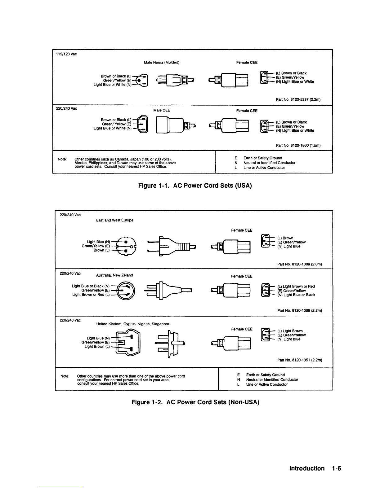
The computer or system also must be properly protected by fuses or circuit breakers of sufficient
capacity to carry the current load specified for the computer or system. Refer to Figures
1-2
for descriptions of the various types of ac power cord configurations.
1-1
and
Cooling Requirements
No external cooling
airflow as long as the computer or system
1-1
in Table
and the front and rear grills are not obstructed.
Four fans provide approximately
Half of the airflow is used to cool the power supply, and half the airflow
is
required for the computer or system. The internal fans provide enough
is
operated within the temperature limitations specified
10.1
cubic meters per minute
(360
CFM) front-to-rear airflow.
is
card cage.
Mounting Considerations
You
can use the computer either free-standing on a table, or mounted in a standard
If
(19-inch) equipment rack.
mounted equipment rack. Refer to Table
mounting the
A990 on a table, provide enough clear space at the front and back of the computer
to permit an unimpeded intake and exhaust of airflow.
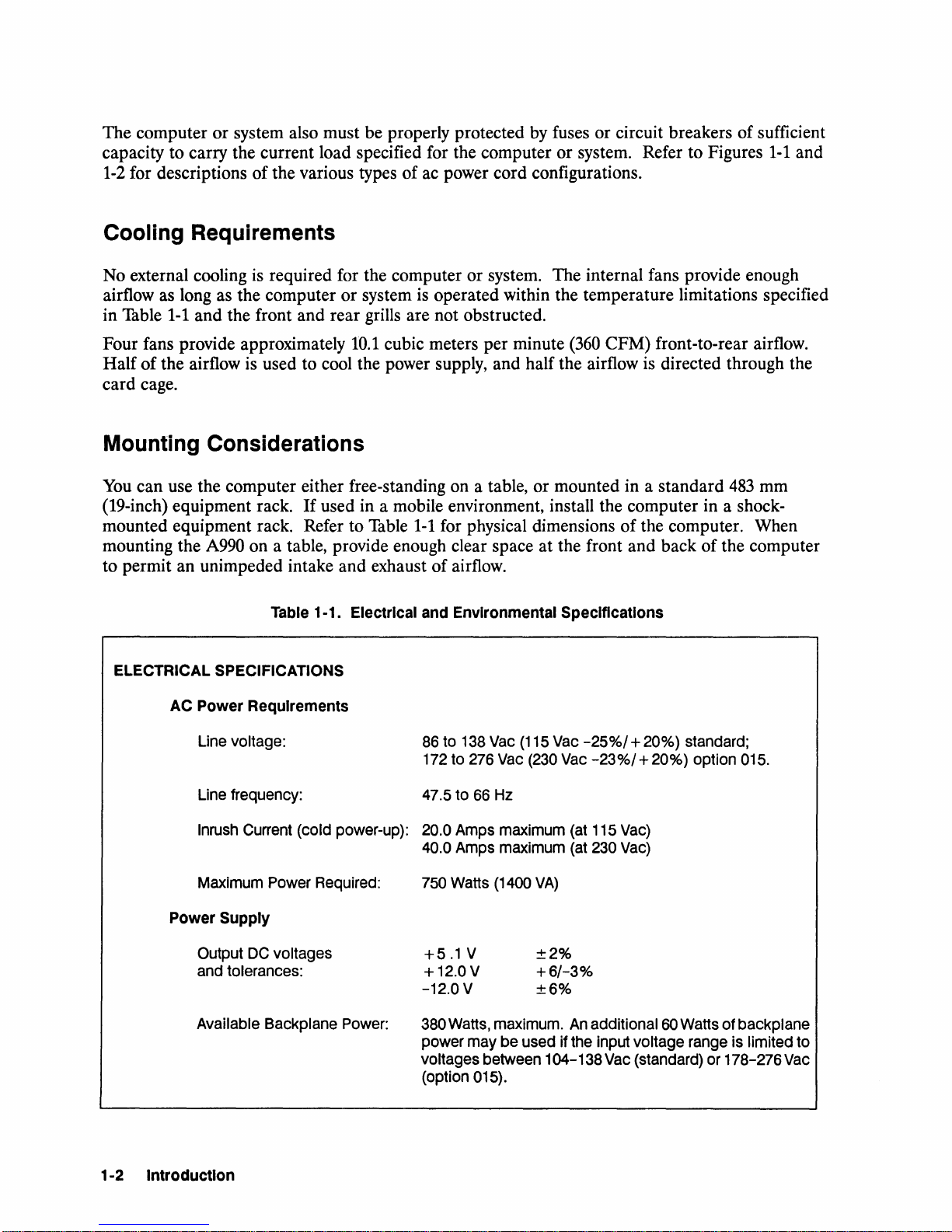
Table 1-1. Electrical and Environmental Specifications
ELECTRICAL SPECIFICATIONS
AC Power Requirements
used in a mobile environment, install the computer in a shock-
1-1
for physical dimensions of the computer. When
directed through the
483
mm
Line
Line
Inrush
Maximum
Power Supply
Output
and
tolerances:
Available Backplane
1-2 Introduction
voltage:
frequency:
Current
Power
DC
voltages
86
to
172
47.5
(cold power-up): 20.0
40.0
Required:
750
+5.1
+ 12.0 V
-12.0
Power:
380
power may be used if
voltages between 104-138
(option 015).
138
to
276
to
66
Amps
Amps
Watts
V
V
Watts,
Vac
(115
Vac
(230
Hz
maximum
maximum
(1400
VA)
±2%
+6/-3%
±6%
maximum.
Vac
Vac
(at
(at
An
the
-25%/
+ 20%) standard;
-23
%/
+ 20%) option 015.
115
Vac)
230
Vac)
additional
input voltage
Vac
60
(standard)
Watts
range
or
of backplane
is limited
178-276
to
Vac
Page 18
Table
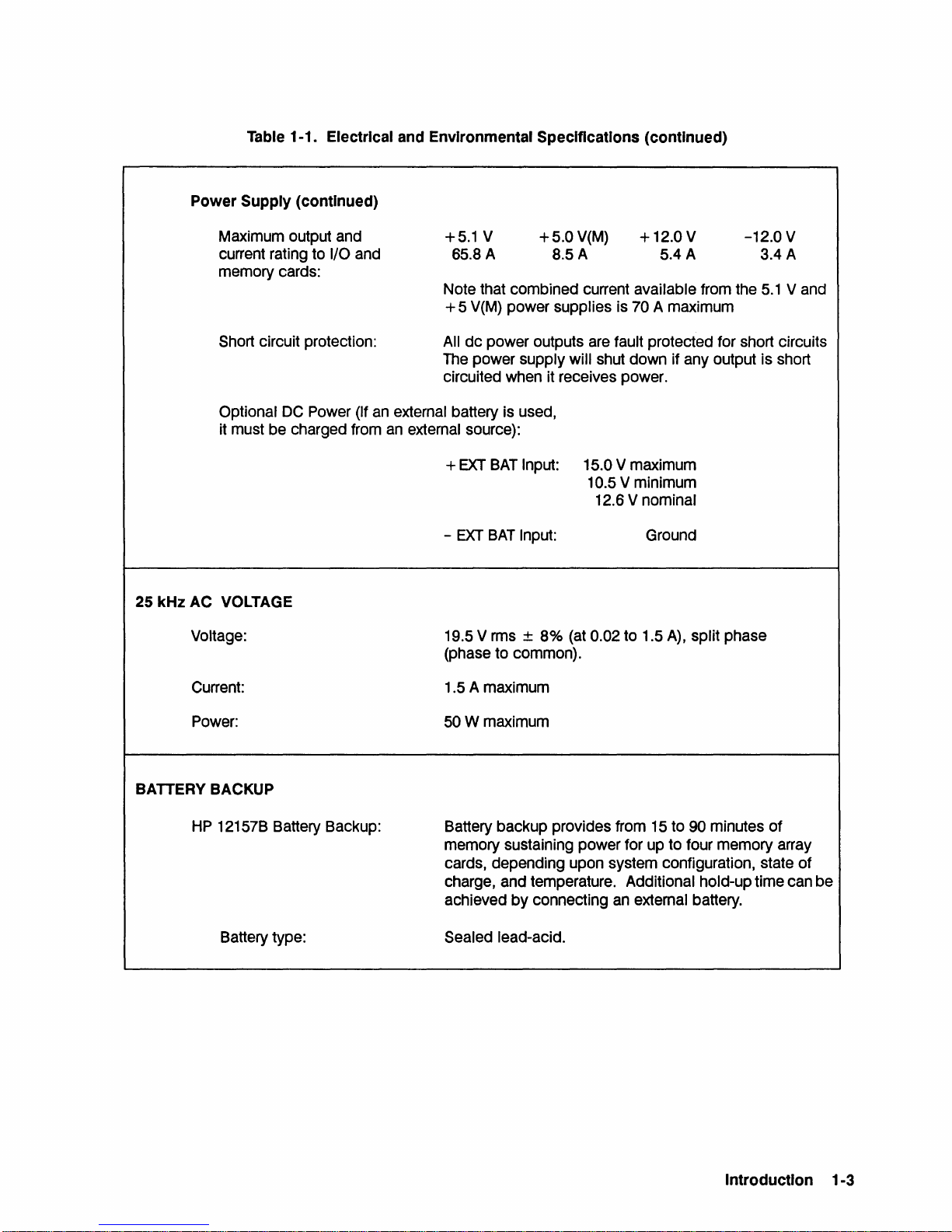
1-1. Electrical and Environmental Specifications (continued)
Power
Supply (continued)
Maximum output and
current rating to
memory cards:
Short circuit protection:
Optional
it must be charged from
DC
25 kHz AC VOLTAGE
Voltage:
I/O and
Power (If
+5.1 V
65.8 A
Note that combined current available from the
+5
V(M) power supplies is 70 A maximum
All
dc
power outputs are fault protected for short circuits
The power supply will shut down if any output is short
circuited when it receives power.
an
external battery is used,
an
external source):
EXT
BAT
+
-
EXT
BAT
19.5 V rms ±
(phase to common).
+5.0
V(M)
8.5A
Input: 15.0 V maximum
10.5 V minimum
Input: Ground
8%
(at
0.02 to 1.5
+ 12.0 V
5.4 A
12.6 V nominal
A),
-12.0 V
split phase
3.4 A
5.1
V and
Current:
Power:
BATTERY BACKUP
HP
12157B Battery Backup:
Battery type:
1.5 A maximum
50Wmaximum
Battery backup provides from 15 to 90 minutes
memory sustaining power for up to four memory array
cards, depending upon system configuration, state
charge, and temperature. Additional hold-up time can be
achieved
Sealed lead-acid.
by
connecting
an
external battery.
of
of
Introduction 1-3
Page 19
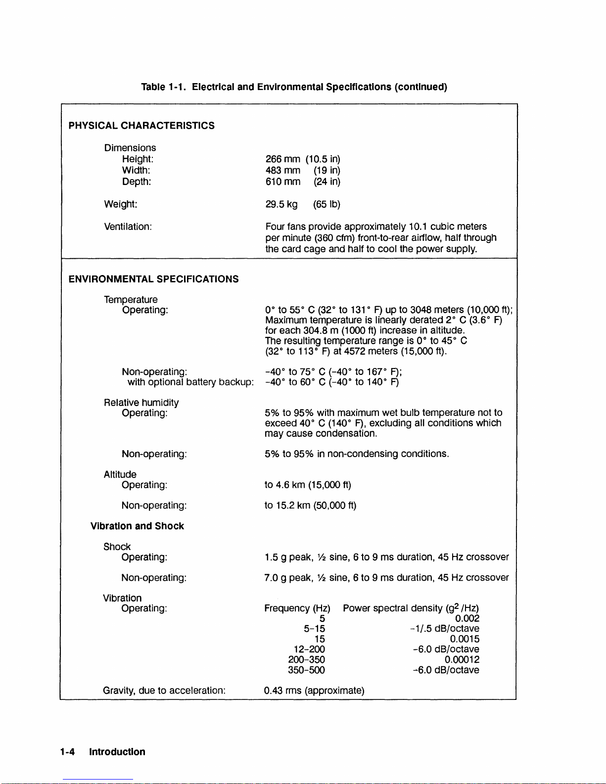
Table 1-1. Electrical and Environmental Specifications (continued)
PHYSICAL CHARACTERISTICS
Dimensions
Height:
Width:
Depth:
266 mm (10.5
483
mm
(19
610 mm
(24
in)
in)
in)
Weight:
Venti lation:
ENVIRONMENTAL SPECIFICATIONS
Temperature
Operating:
Non-operating:
with optional battery backup:
Relative humidity
Operating:
Non-operating:
Altitude
Operating:
29.5 kg
Four fans provide approximately
per minute
the card cage and half to cool the power supply.
0° to 55° C (32° to
Maximum temperature is linearly derated 2° C (3.6°
for each 304.8 m (1000
The resulting temperature range is
(32° to
-40°
-40°
(65
Ib)
10.1
cubic meters
(360 cfm) front-to-rear airflow, half through
131
°
F)
up to 3048 meters (10,000
ft)
increase in altitude.
0° to 45° C
113
°
F)
at 4572 meters (15,000
to 75° C (-40° to 167°
to 60° C (-40° to 140°
F);
F)
ft).
F)
5% to 95% with maximum wet bulb temperature not to
exceed
may cause condensation.
40° C (140°
F),
excluding all conditions which
5% to 95% in non-condensing conditions.
4.6 km (15,000
to
ft)
ft);
Non-operating:
Vibration and
Shock
Operating:
Non-operating:
Vibration
Operating:
Gravity, due to acceleration:
1-4
Introduction
Shock
to 15.2 km (50,000
1.5 g peak,
Y2
ft)
sine, 6 to 9 ms duration,
45
Hz crossover
7.0 g peak, % sine, 6 to 9 ms duration, 45 Hz crossover
Frequency
(Hz)
5
5-15
15
12-200
200-350
350-500
Power spectral density
-1/.5
dB/octave
-6.0
dB/octave
~6.0
dB/octave
(g2
/Hz)
0.002
0.0015
0.00012
0.43 rms (approximate)
Page 20
115/120 Vac
220/240Vac
Brown or Black
Green/Yellow
Light Blue or White (N)
Brown
Green/ Yellow
Light Blue
'"
Blad<
or
White (N) r
(E)
(E)
Male Nema (Molded) Female CEE
(l)~
crn{-§
~
MaleCEE
II.)
:(J
~
~
Female CEE
a::
(l) Brown
(E) Green/Yellow
(N) Light Blue or White
Part No.
~
(l)
Brown or Black
(E)
Green/Yellow
(N) Light
Part No.
or
Black
8120-5337 (2.2m)
Blue or White
8120-1860 (1.5m)
Note:
Other countries such as Canada, Japan
Mexico, Philippines, and Taiwan
power cord sets.
220/240Vac
Green/Yellow
220/240Vac
Ugh!
Blue
Green/Yellow
Light Brown or Red
220/240 Vac
Green/Yellow
Light Brown (l)
Note: Other countrtes
configurations. For correct
consult your nearest HP Sa es Office.
Consult your nearest HP Sales Office.
East and West Europe
Ugh!
BI,.
Brown (l)
Australia, New Zeland
0'
BlaOk
United Klndom, Cyprus, Nigeria,
Ugh!
BI,.
may
(100 or 200 volts),
may
use some of the above N
Figure 1-1. AC Power Cord Sets (USA)
IN)
~
(E)
~
IN)
=©
(E)
(l)
IN)
~
(E)
~
Singapore
•
use more than one of the above power cord
Fe0wer
cord set In your area,
E Earth or Safety Ground
l
FemaieCEE
~
FemaieCEE
~
FemaieCEE
~
--
Neutral or Identified Conductor
Line
or
Active Conductor
(l) Brown
(E)
~
(N) Light Blue
Part No. 8120-1689 (2.0m)
(l) Light Brown or Red
(E)
(N) Light Blue or Black
~
Part No. 8120-1369 (2.2m)
~
(l) Light Brown
~
(E)
(N) Light Blue
Part No. 8120-1351 (2.2m)
or
Safety Ground
Earth
E
N
l
Identified Conductor
Neutral or
Line or Active Conductor
Green/Yellow
Green/Yellow
Green/Yellow
Figure 1-2.
AC
Power Cord Sets (Non-USA)
Introduction 1-5
Page 21

Unpacking and Inspecting
Your A990 computer or system may be shipped in several containers. Verify the number of
containers received against the carrier's paperwork. Inspect each container for damage that may
If
have occurred during transit.
carrier be present when you open the container.
Open the shipping container marked "MANUALS AND ACCESSORIES" and locate the
materials list. Compare it with your purchase order. Make sure it includes everything you have
ordered. Unpack the shipping container(s) and inspect each item for external damage, such as
broken controls and connectors, dented corners, bent panels, scratches, and loose components.
Also check the rigid foam-plastic packing material (if used) for signs of deformation or cracking.
Such signs may indicate rough handling in transit.
If
you find damage to the computer or accessories,
below. Be sure you keep
settling a claim, or to repackage the computer or system.
all
you find damage or water stains, request that an agent of the
follow
shipping containers and packing materials.
the damage claim procedure described
You
may need them for
Claims Procedure
If
you need to make a claim, contact your nearest Hewlett-Packard Sales and Service Office.
the loss occurred in transit, notify the carrier as
retain all shipping and packaging materials for inspection. Hewlett-Packard
or replace damaged or lost items even though claims against the carrier may not yet be settled.
well
as Hewlett-Packard, and also be sure you
will
arrange to repair
If
Physical Inventory
Make sure all manuals listed in the bill of materials are included. Your computer's model and
serial number
serial numbers should match those on the packing list.
Hewlett-Packard
computer or system, verify that the cards have been supplied as specified on your purchase order.
is
located on the identification label on the back of the chassis. The model and
If
they do not, immediately contact your
Sales and Service Office.
If
you have ordered I/O or memory cards with your
1-6 Introduction
Page 22

Installation
2
This chapter describes procedures for configuring and installing the A990
and system.
Required Tools
Slot and Phillips head screwdrivers are the only tools you
system.
cards.
We
strongly recommend the use of a wrist strap and ground cord when handling plug-in
will
need to install the computer or
Configuration Requirements
Verifying the Power Supply Configuration
Warning
G
To
avoid damage
adjustments,
only by qualified maintenance people.
or
to
equipment
repair
or
injury
to
the power supply must be performed
to
people, any service,
20-s10t
box computer
The computer's ac line voltage configuration
configuration power connector. The power connector must be plugged into one of two connectors
(P7 or P8) located at the left side of the power supply when viewing the computer from the front.
See Figure
connectors P7 and P8. For
P8. For
To
check the position of the ac line configuration/fan power plug connector, remove the computer
front panel and fan panel and inspect the position of the power line connector relative to sockets
P7 and P8. The ac power cord
configuration connector
panel, refer to Chapter 3 of this manual.
230
2-1
for a
view
of the power supply from the front, and Figure
Vac
operation, the connector must be plugged into socket P7.
is
is
determined by the position
115
Vac
operation, the power connector must be plugged into socket
is
always connected to plug P9 regardless of how the line
set. For step-by-step information on removing the front panel and fan
of
the line
2-2
for the location
Installation 2-1
of
Page 23

B. B.
ON
Terminal
Positive
Battery
Terminal
Figure 2-1. Front View of Chassis with Bezel and
Battery
Backup Terminal
Assembly
B. B.
OFF
Fan
Negative
Battery
Terminal
Panel Removed
Battery Backup
The
HP
12157B
system configuration, state of charge, and temperature. Additional memory hold-up time can be
achieved by connecting an external battery.
If
Battery Backup
ENABLE. The switch
position if the power is turned off and if memory backup
be set to DISABLE if cards are to be connected or disconnected from the backplane.
Refer to the
battery backup. Note that if batteries are not installed, the strapping connector from the terminal
on the lower board of the power supply must be connected to B.B.
batteries are installed, the strapping connector must be connected to B.B. ON.
Battery Backup
is
installed, set the Battery Enable switch on the back panel of the computer to
is
shown in Figure
will
sustain memory for
2-3.
15
to
90
minutes, depending on the
This switch should be set to the DISABLE
is
not required. The switch should also
Battery Backup Installation section later in this chapter for instructions on installing
OFF. (See Figure 2-1.)
If
2-2 Installation
Page 24

B
P9
pSL-1
P7L-1
___
___
....J
....J
(Toward
Front
of
Power Supply
Fan
Panel and Front Panel)
P2
P1
P5
[!!l
Connector
P1
P2
P5
P6
P7
PS
P9
P14
-
Figure
Description
DC
Output Connectors
DC
Output Connectors
Battery Switch Connector
Test Points and External Battery Connector
230 Vac Line Configuration Connector
115 Vac Line Configuration Connector
AC
Line Input Connector
Battery Backup
2-2.
Power
OFF Connector
Supply
Connector
Diagram
-
Figure
2-3.
Computer
Back
Panel
and
Power
Panel
Installation
2-3
Page 25

A990
CPU
Card Switches
The A990 CPU card contains two switches, SWI and
action (push and release) reset switch that resets the A990
DIP switch (see Figure
1.
BOOT
2.
Autorestart override (Memory Lost), which sets the conditions under which autorestart
occurs.
SELECT, which selects computer operations at power-up.
2-5)
that controls the following functions:
· .
· .
· .
..
· .
..
..
..
..
..
..
..
..
..
..
..
..
..
..
..
..
..
..
..
..
..
..
..
..
..
..
..
..
..
..
..
..
..
..
· .
0
~
2
m
Cti
C
..
· .
. .
..
. .
. .
· .
. .
..
. .
. .
. .
..
. .
. .
. .
..
. .
.
.
. .
· .
. .
. .
..
. .
.
.
. .
. .
. .
. .
. .
..
. .
. .
. .
..
. .
..
..
SW2
(s,ee
Figure
CPU card. SW2 is an eight-section
SW1
2-4).
SWI is a momentary
2-4 Installation
Firmware
EPROM
Figure 2-4. A990
A bank
board,
CPU
Card Switches
of 4 LEOs
directly below the upper bank
is located on the lower side
SW1
and SW2
of
8 LEOs.
of
the
Page 26

Startup Option Switches
There are eight switches,
SW2-1
through
SW2-8,
that control the startup options. Table
specifies the available startup options and corresponding switch settings.
Autorestart Switch
Autorestart
1.
DOWN
autorestart or if battery backup is not installed. When using the
be sure you set the Battery Enable switch to DISABLE.
When
that was running prior to the powerfail condition. Instead, the boot loader (or
routine)
2.
UP (oft) - Autorestart
is
restart the program that was running prior to the powerfail condition. With no battery
backup installed, you
is
controlled by switch
(on) - Autorestart
SW2-8 is ON, if power
will
execute.
set to ENABLE.
SW2-8
is
not enabled. Use this setting if you do not wish to use
is
is
enabled if battery backup is installed and the Battery Enable switch
If
power
will
is
get a self-test error when you switch the computer on.
(see Figure
lost, the autorestart feature
2-5).
The settings for switch SW2-8 are:
ON
position for
will
not restart the program
lost and memory was sustained, autorestart
will
2-1
SW2-8,
VCP
automatically
Figure 2-5. Switch SW2 In Default Configuration
Installation 2-5
Page 27

Table 2-1. SW2 Start-Up Switch Settings
Computer Action
S1
Loop on self-test Test 2 regardless of error. D D
Loop on
Run
For the
is restarted (JMP 4B).
VCP will execute. When a loader finishes an autoboot, it starts execution
self-test Test 2 and stop on error.
Virtual Control Panel
following switch settings, the computer action indicated will occur if memory is lost, otherwise, the program
VCP.
Run
Speed sense and run
Execute program from
must have
Load and execute the program via the HDLC
the
to loader command %BDS. **
Load and execute program from the first file of the disk (via HP-IB
To
autoboot via HP-IB
and, for
dress
select code 22. This is equivalent to the loader command %BRM. **
HDLC
or
LAN card, the card must have select code 24. This is equivalent
HP-IB, the disk drive must have HP-IB address 2
6.
This is equivalent to the loader command %BDC. **
(VCP)
routine on completion of self-test.
If the autorestart feature is disabled (switch SW2-8 down), the program cannot restart and
VCP.
See Notes 2 and
PROM card. In order to autoboot from PROM, the card
or
SCSI, the interface card must have select code 27;
3.
or
LAN card.
To
autoboot via U
or,
for SCSI, ad-
of
the loaded program at location 02.
or
SCSI). U U U
D D
D
U
U U
U
Swlt~h~~*
S2 S3 S4 S5 S6 S7 S8
D D
U
U U
D D D
D
D
U
D D z
U
D z
D z
U
D z
D
Y
Y
Y
Y
Y
Y
Y
Y
D M
D M
D M
M
D
D M
M
D
M
D
D M
z
z
z
z
Execute bootstring from the time-of-day clock
the A990
*
**
Notes:
CPU card.
D = Down (On); U =
Refer to the
=
D,
y
=
U,
y
=
D,
z
z =
U,
M =
M =
1.
2.
3.
HP
normal mode, system console uses ENQ-ACK handshaking.
system console does not use ENQ-ACK handshaking.
normal mode, break enabled.
break disabled (but not halts).
D,
disable autorestart (battery backup not installed).
U,
enable autorestart (battery backup installed).
Do not use any switch combination that is not specified above.
Use this switch configuration for normal computer operation.
Speed sense allows VCP to execute at any baud rate supported
Up
(Off)
1000 A990 Computer Reference Manual, part number 02959-90001.
RAM
(non-volatile
RAM)
on
D D
D
by
the 8-channel MUX.
U z
Y
D M
2-6 Installation
Page 28

Interface Card Switches
Assign each I/O interface card to be installed in the computer a unique select code by setting the
select code switches on the interface cards. Refer to the appropriate interface card reference
manuals for select code switch information and for information on any other card switches that
must be set.
Virtual Control Panel (VCP) Configuration
If
you are installing a Virtual Control Panel (VCP), assign one of your
(HP
12005B),
cards as the VCP interface card.
LAN (HP
12076A),
or HDLC (HP
12007B
Modem or
MUX
HP
(HP 12040D), ASIC
12044A Direct Connect)
Set switch U1S1 on that card to
ON
(closed) to designate it as the VCP interface card.
Memory Configuration
Several memory configurations, using
can be installed in the
memory configurations. All three array sizes may be used together in the same system provided
that the largest memory card
can be installed in the
and frontplane connectors. Refer to the
instructions on installing memory.
A990.
A990 computer. Refer to Table
Refer to Figure
is
768
Kbyte, 3 Mbyte and/or 8 Mbyte memory array cards,
2-6
for an illustration of minimum and maximum
closest to the A990 CPU card.
2-2
for the available memory array cards
Memory Installation section in this chapter for
Up
to four memory array cards
Installation 2-7
Page 29

Minimum A990 Memory Configuration
slot #
11
Available for I/O Card 1
12
Available for
13
Available for I/O Card
14 Available for
15
Available for
16 Available for
17 Available for
18
Available for I/O Card
19
Available for I/O Card
20 Available for I/O Card
§!Q1it
11
Available for I/O Card 1
12 Available for
13
Available for I/O Card
14 Available for
15 Available for
16
Available for I/O Card
17 Available for
18 Available for
19
Available for I/O Card 9
Available for I/O Card
20
I/O Card 2 12220A 768
I/O Card 4 Available for I/O Card
I/O Card
I/O Card
I/O Card
I/O Card
I/O Card 4
I/O Card
I/O Card 7 Available for I/O Card
I/O Card
§!Q1it
A990 CPU Card
12oo9A HP-IB Interface Card
3
Available for I/O Card
5
Available for I/O Card
6
7 Available for
Available for I/O Card
8
Available for
9
Available for I/O Card
10
Maximum A990 Memory Configuration
slot #
A990 CPU Card
12221
2
3
5
6
8
10
B 8 MB Memory Array Card
12221
B 8 MB Memory Array Card
12221
B 8 MB Memory Array Card
12221
B 8 MB Memory Array Card
12009A
Available for I/O Card
Available for
Available for I/O Card
HP-IB Interface Card
Figure 2-6. A990 Memory Configurations
KB
Memory Array Card
I/O Card
I/O Card
I/O Card
12220A 768 KByte Memory Array Card
12221A 3 MByte Memory Array Card 12221-60001
12221
Connector for 1 Memory Card
Connector for 2 Memory Cards
Connector for 3 Memory Cards 12230-60003
Connector for 4 Memory Cards
2-8 Installation
Table 2-2. Memory Array Cards and Frontplanes
Description Part Number
12220-60001
B 8 MByte Memory Array Card 12221-66001
12230-60001
12230-60002
12230-60004
Page 30

I/O Priority Assignment
Each peripheral device in the system must be connected to the computer system through an
interface card installed in the card cage. A priority chain connects all interface cards in series to
prioritize simultaneous
priority of an interface card
after the last memory card having the highest priority and slot
Figure
installing interface cards in the desired order
I/O requests from a higher priority device inhibit lower priority requests by breaking the priority
chain.
peripherals. Consult the system manager to establish
cards accordingly.
2-7
for an illustration of the I/O priority assignments. Configuring I/O priority consists of
To
maximize system response time and efficiency, assign the higher priorities to high-speed
DMA
requests and interrupt requests from two or more peripherals. The
is
determined by the slot the card occupies, with the slot directly
20
having the lowest priority. See
of
priority.
I/O device priority and install the interface
Note
"
Correct computer operation requires that there be NO vacant slots
between plug-in cards.
Memory Array
Card
Memory
Frontplane
Connector
Cable to I/O Device
with Lowest Priority
Figure 2-7.
Cable
to I/O Device with
Highest Priority
(System Disk Drive)
HP
2959/2999 Cards and I/O Priority Assignments
A990 CPU
Card
Installation 2-9
Page 31

Installation Procedure
Battery Backup Installation
The A990 Computer or System accommodates an optional battery backup, which you can install
To
in the power supply compartment.
1.
Make sure that the ac power cord is not connected to the computer chassis and that the ac
LINE switch is set to the
Enable switch on the back of the chassis to DISABLE.
2.
Remove the front panel, the fan panel, and the ac line configuration/fan power connector
from the chassis. Note whether the connector is attached to
Refer to Chapter 3 of this manual for instructions on removing these assemblies.
3.
If
the strapping connector
supply marked "B.B.
ON".
4.
Place the battery bracket over the battery. Align the negative (-) terminal of the battery with
the label on the battery bracket that reads
See Figure
2-1.
OFF
is
OFF", connect it to the terminal on the upper board marked "B.B.
install the battery backup:
position.
connected to the terminal on the lower board
If
you have not already done so, set the Battery
P7
(230
Vac)
"Black Wire (-)". See Figures
or
to P8
of
the power
2-8
and
(115
2-9.
Vac).
5.
On the right side of the chassis, locate a pair of wires (a white covered wire and a black
covered wire) in a gray sheath. Connect the terminal lug on the white wire to the positive
( + ) battery terminal and connect the terminal lug on the black wire to the negative (-)
battery terminal. See Figure
6.
Place the battery, bracket, and attached wires in an upright position in the battery tray
beneath the power supply.
not upward. See Figure
bracket assembly under the power supply as you set it into place. Rotate the battery and
bracket assembly so the battery terminals face upward. See Figure
screws on the battery bracket.
7.
Reinstall the fan panel and front panel. Remember to reconnect the line configuration
connector to
complete instructions.
P7 or P8, as appropriate for your line power voltage. Refer to Chapter 3 for
2-9.
Place the assembly so the battery terminals are facing outward,
2-10.
The fit
is
close, so you may have to maneuver the battery and
2-11.
Fasten the captive
2-10 Installation
Page 32

Place bracket
over
battery
Figure 2-8. Backup Battery and Battery Bracket
Allach battery cable
terminal lugs onto
battery terminals.
I
I
I
White wire
l
Black wire
Figure 2-9. Backup Battery Installed
In
Battery Bracket
Installation
2-11
Page 33

Battery
Assembly
Battery
Terminal
(Negative)
Figure 2-10. Battery Assembly
Positive
Battery
Terminal
Battery
Backup
Assembly
In
Initial Position
B. B.
Terminal
B.
B.
Terminal
OFF
ON
Negative
Battery
Terminal
Figure 2-11. Battery Assembly
2-12 Installation
In
Final Position
Page 34

Memory Installation
Caution
I
You
can install from one to four memory array cards in the A990 card cage. With available
memory cards, you can install up to
ECC memory array cards. The memory frontplane connectors, however, are unique to the
A900 memory frontplane connectors cannot be used with the
types of memory array cards and frontplanes.
Install the first memory array card in the slot immediately to the left of the
immediately to the left of the first, and so on.
CPU card and a memory array card or between any memory array cards.
array cards of different capacities, place the largest capacity card(s) nearest the
Install the appropriate frontplane connector using one of the four supplied with your computer.
Attach the small connector of the frontplane to the
memory array card(s). Be sure you use a frontplane that matches the number of memory array
cards you have installed. For example, if you have installed four memory array cards, the
frontplane must have
STATIC SENSITIVE DEVICES you install or remove memory cards, you
switch to DISABLE. Also, make sure the LINE switch is set to
the ac power cord
antistatic wrist strap connected to a ground wire.
five
connectors.
is
not connected to the ac power mains. Wear an
32
Mbytes of memory. The A990 supports only the A900
To
avoid damage to equipment, before
must set the Battery Enable
A990.
Do
not leave an empty backplane slot between the
CPU card and the other connector( s) to the
Table
2-2
lists the available
CPU card, the second
If
you have memory
OFF
and
A990.
A990 CPU card.
I/O Card Installation
Install I/O cards the same way you installed the CPU and memory cards.
priorities for
CPU card, the higher the priority. Install
I/O cards are related to their placement relative to the CPU card. The closer to the
all
cards contiguously (no empty slots between cards).
DMA
and interrupt
Self-Test Check
The self-test for the processor automatically executes every time the computer is powered on.
recommended that you run the self-test to ensure that the CPU
must be made with all plug-in cards installed in the computer.
proceed as follows:
1.
Set the LINE switch to the
battery backup is installed, set the Battery Enable switch to DISABLE.
2.
Remove the rear cover for observation of the processor LEDs.
OFF
position and connect the power cord to a power outlet.
is
operating correctly. This check
To
verify the self-test operation,
It
If
is
Installation 2-13
Page 35

3.
Set the power switch to ON. Observe the eight LEDs on the top of the A990 CPU card.
the computer passes the self-test, the LEDs
will
display one of the following values within
seconds. Any other LED display indicates a self-test failure. Refer to Chapter 3 for
troubleshooting information.
If
20
000001*1- VCP program
000000*0 - VCP program
VCP console to respond to the first Enq/ Ack handshake.
is
00000001
00000000
10000000
- Loader
- User software
- Loader error. Probably a checksum error; change media on loading device.
where: 1
for the
= LED lit; 0 = LED unlit; * = LED blinking
is
running; VCP console is connected.
is
running; VCP console
running.
is
running.
is
not connected, that
is,
VCP
is
waiting
Computer Mounting
Table Mounting
The computer may be used as a freestanding instrument in a land-based environment. The only
considerations are that adequate space should be allowed at the front and rear to ensure
intake and exhaust of ventilating air, and that all covers are installed. Also, a minimum of
centimeters
(15
inches) of clearance behind the computer
is
required when removing and
installing plug-in cards.
full
38
Rack Mounting
You
can mount the A990 Computer in any standard 19-inch cabinet, such as the
HP
29431G.
The usual location for the computer
is
at the bottom of the cabinet. Refer to the
HP
29429A or
manuals supplied with your cabinet for specific information on installing mounting rails, installing
the computer chassis, and grounding requirements.
When installing the
power cord to the ac power socket in the chassis and the other end to the
(PDU) mounted on the back door of the cabinet.
switch
is
set to OFF, then remove the four screws that secure the
HP 2959A CPU or the
HP
2999A SPU in a cabinet, connect one end of the ac
Power Distribution Unit
To
access the PDU, make sure the Main Power
PDU
access panel.
2-14
Installation
Page 36

System Console (Terminal) Installation
Except for the cabling information given in this section and in Figure
2-12,
refer to the
documentation supplied with your terminal for all other installation information. For information
on configuring the console interface as the Virtual Control
Virtual Control Panel Configuration section
in
this chapter.
Panel (VCP) interface, refer to the
Use one of the following interfaces for your system console:
HP
12005B
HP
12040C/D Multiplexer Interface (MUX) Card
Asynchronous Serial Interface (ASIC) Card
Use the following procedure to connect your terminal to the interface card:
1.
Set the system power switch to
OFF
and, if battery backup is installed, set the Battery
Enable switch to DISABLE.
2.
Remove the computer card cage rear cover.
3.
If
you connect the terminal with an electrical cable (instead of a fiber optic cable), connect
the cable's hooded connector to the interface card, with the cable extending down. Connect
the ground lug from the hooded connector to the computer chassis.
4.
If
you connect the terminal with a fiber optic cable (to the
HP
12005B
ASIC card only),
connect the gray connector on the cable to the gray transmitter on the interface card and the
blue connector on the cable to the blue receiver on the interface card.
If
an
HP
12040
MUX
is
used as the VCP interface, the VCP terminal must be connected to
Port 0 of the MUX.
If
your terminal is connected to an ASIC card or to revision C of the
must configure the terminal for
If
you are using revision D of the
to operate at the baud rate of your
9600
HP
HP
baud rate.
12040
MUX card, the computer
terminal.
You
must have your terminal configured for the
ENQ/ACK protocol and 8 data bits with no parity or 7 data bits with
1200,2400,4800,9600, and
You
may also use one
19.2k
are supported for terminals connected to an
of
the following I/O interfaces as your VCP interface for remote VCP
HP
12040
MUX
is
automatically configured
O's
parity. Baud rates
HP
card, you
12040
MUX.
download and boot capabilities:
HP 12076A
:HP
12007B
If
you want to use the LAN card as your VCP interface, refer to the
and Installation Manual,
If
you want to use an HDLC card as your VCP interface, your remote system must be running
either
NS-ARPAl1000 or DS/1000-IV software.
refer to the NS-ARPA/lOOO Generation and Initialization Manual,
information on remote
DS/1000-WTheory
information on remote
LAN/IODO
or
HP
12044A
part number
VCP.
o/Operation
VCP.
Link Interface Card
HDLC Interface Card
92077-90034,
If
your remote system
and
Troubleshooting Manual, part number
RTE-A
for information on remote
If
your remote system is running NS-ARPAl1000,
part
is
running DS/1000-IV software, refer to the
System Generation
VCP.
number
91790-90030,
91750-90014,
for
300,
for
Installation 2-15
Page 37

Interface Cabling
Refer to the manuals supplied with your interface cards and peripherals for information on
connecting devices to
procedure to install the interface cables:
1.
Set the power switch to
switch to DISABLE. Remove the rear panel.
2.
Connect the hooded connector of each cable to the edge connector of the appropriate
interface card, with the cable extending to the bottom of the card cage. Connect the cable
ground wire, if present, to the grounding strip.
3.
Connect the other end of each cable to the appropriate peripheral device. Reinstall the rear
panel.
I/O cards. After all interface cables have been assembled, use the following
OFF
and, if battery backup is installed, set the Battery Enable
Memory Frontplane
ill
I A990
C
d C
ar age
CPU
Card
V Connector
~-
v
I Memory Array
l HP-IB or SCSI
I
ASICorMUX
ill
As additional memory array cards are added, the appropriate frontplane connector must
array frontplane part numbers
respectively.
~
When installing the optional
cabling information. Note that revision
terminal.
~
Connect gray connectors to gray transmitters; connect blue connectors to blue receivers.
* Portions
or
all
of
this product line are discontinued; shown for reference only.
HP
~
_ CS/80 or SCSI
r-
Disk Drive
Jt---+----------I'------~
~
E-~------
,,/
..-------.
239x*
Terminal
......
Alternate System Console Configurations
12230-60001 through -60004 connect one through four memory array cards,
12040 MUX card, refer to the card manual, part number 12040-90123, for
0 of the MUX senses and sets the baud rate
5061-5798 (Fiber Optic) ~
--;------,
/ I I
5061-6634
I
r::::::=-1
I
~~OO_1~*
I
~~~:~~
~I~
J.
Is061J
r
l.§.8QQ
I I 262x* I
I I
Terminal
L..
____
Fi~r
OptiC
Adapter
1 ,
I
J
be
used. Memory
to
match that of the
2-16
Installation
Figure 2-12. System Cabling Diagram
Page 38

Disk Drive Installation
A variety of disk drives are available for use with A990 computers and systems. Except for
installing the
for installation information. Use the following instructions to install your disk drive cabling:
HP-IB or SCSI cable, refer to the installation manual supplied with your disk drive
Note
"
1.
Set the system power switch to
2.
Connect the HP-IB or SCSI connector on the disk drive cable to the HP-IB or SCSI
connector on the back of the disk drive.
3.
Connect the hooded connector on the disk drive cable to the
Card or
cage.
4.
Install the rear panel.
Where both standard and high-speed disk drives are used in a multiple
drive installation, assign one
OFF
HP
12016A
SCSI Interface Card, with the cable extending to the bottom of the card
HP-IB Interface Card to each class of drive.
and remove the rear panel of the computer.
HP
12009A HP-IB Interface
Powering Up the System and Booting
Use the following procedure to complete the installation and power up the system:
1.
Set the terminal Power switch to ON; then set the system Power switch to ON.
backup
appear on the terminal screen after approximately
the
is
installed, set the Battery Enable switch to ENABLE. A blinking cursor
15
seconds. Press carriage return to get
VCP power-up message which displays the following:
If
battery
will
• 110 table with the select code, ID number, and revision of each installed 110 card
• Pretest errors, if present
• CPU identification
• Amount
• Contents of selected registers
Table
of
memory installed
2-3
gives the ID number for each A-Series interface card.
Installation 2-17
Page 39

The following is an example YCP power-up message for a system with an
card at select code
27
and an
HP
12005B
ASIC card at select code
20
and designated as the
YCP interface:
HP
12009A HP-IB
Installed
ID Rev
004
000
(Pretest
HP
1000
A-Series
A990
CPU
P
00000
A
000002
VCP>
Note that the A-Register contains the number
contains the revision
the
A990 firmware EPROM.
2.
Boot up the RTE-A Primary System using the instructions given in the
System Software Installation Manual,
I/O
Cards
SC
0 27
1 20
Error
M
Message)
8192KB
00000
B
004022
of
<-
VCP
(this message appears only if an error was detected;
3,
Y
000000
cards found by YCP; the B-Register
?
for
MEMORY
T
Help
000000
X
refer to Chapter
RW
000000
000003
of
I/O
the YCP code; and the X-Register contains the revision number of
part number
92077-90038.
Verifying Computer Operations
A990
Self-Test Programs)
E 0 o 0
RTE-A
Primary
You
can use the diagnostic programs supplied with the
5270
or later) to verify the installation and operation of your A990 CPU. Complete
HP
24612A Diagnostic Package (Revision
documentation is supplied with the package.
Primary System Backup
Use the appropriate backup utility to back up the Primary System. Refer to the
Manual,
part number
92077-90004.
RTE-A
Utilities
2-18 Installation
Page 40

Table 2-3. A-Series I/O Interface Card
10
Number Rev. Number Interface Card
10
Numbers
000 0
000
001
002
002
003
003 0
004 0
005
006
022
023
025
040
** **
044
060
061
102
102
102
102
102
102
102
106
115
126
141
143
177 7
HP 12005A*
1
0
0
0
0
0
0
0
0
0
0
0
0
0
0
0
0
0
0
0
0
0
0
0
0
0
HP
12005B
HP
12oo6A Parallel Interface Card
HP
12043A Multi-Use Programmable Serial Interface
HP
12092A Data Link Master Interface Card
HP12008A PROM I/O Card
HP
12155A A700 PROM Control Store Card
HP12009A HP-IB Interface Card
HP
12010A Breadboard Card
HP
12041B Multi-Use 8-Channel MUX Interface Card
HP
37222A Integral MODEM Interface Card
HP
12022A
HP
12065A
HP
12060A*/B
HP
12061A
HP
12062A
HP
12153A A700 Writable Control Store Card
HP
12205A A900 Writable Control Store Card
HP
12007B HDLC (Modem) Card
HP
12044A HDLC (Direct Connect) Card
HP
12042A
HP
12042B Programmable
HP
12073A
HP
12075A
HP
12082A DS/1000-IV Direct Connect Interface to
HP
12040B* /C/D 8-Channel Multiplexer Interface Card
HP
12016A
HP 12076A
HP
12063A
HP
12072A
HP
12100A
Asynchronous
Asynchronous
Integrated Disk Interface Card
Color Video Interface Card
High
Level Analog Input Card
Analog Multiplexer Expansion Card
Digital-to-Analog Card
Programmable Serial Interface
DS/1000-IV Modem Interface to
LAP-B Network
SCSI Interface Card
LAN
Interface Card
161N/160UT Isolated Digital Card
Data Link
A400 Processor Card On-Board
Interface Card
Interface Card
S~rial
Interface (Direct Connect) Card
Interface Card
Slave Interface Card
(Modem) Card
HP
3000
HP
3000
I/O (not an I/O card)
Discontinued product; shown for reference
*
**
Has no I/O master or
ID
number.
only.
Installation 2-19
Page 41

Repackaging for Shipment
If
you need to return any part or all of your computer or system to the factory, you can use the
same shipping materials originally used
from Hewlett-Packard
available materials.
Sales and Service Offices. Alternatively, you can use commercially
Shipment Using Original Packaging
When returning an item in its original or factory supplied packaging, use the following procedure:
1.
Attach a tag to the item clearly describing the type of service needed or
returning the item; include the item's model number and serial number on the tag.
2.
Mark the container "Fragile" to assure special handling (although this
proper packaging).
3.
In correspondence dealing with an item, please refer to it by both model and serial numbers.
Shipment Using New Packaging
by
the factory or you can obtain new shipping packages
why
you are
is
no substitute for
The following instructions should be used
commercially available materials:
1.
Wrap the computer in Aircap film or foam.
Hewlett-Packard, first attach a tag to the computer with your return address and indicate the
type of service required. Include the computer model number and full serial number.
2.
Use a strong shipping container large enough to hold the item and enough shock absorbing
material to cushion the item and prevent movement inside the container. A double-wall
carton made of
3.
Seal the shipping container securely and mark it "Fragile".
4.
In any correspondence dealing with the computer, be sure you refer to it by its model
number and serial number.
2.41
MPa (350-psi) test material
as
a guide when packaging the computer with
If
shipping the computer back to
is
adequate.
2-20
Installation
Page 42

3
Service
This chapter describes periodic maintenance procedures, troubleshooting information for
level,
isolating malfunctions to the assembly
computer assemblies.
Electrical Safety
Before proceeding with any maintenance or service on the computer which requires physical
contact with electrical or electronic
safety precautions are followed to protect against shock. Heed all
equipment and in this manual. All service work must be done by qualified personnel.
components, be sure that either power
and procedures for removing and replacing various
is
removed or that
"WARNING" signs on
Periodic Maintenance
Warning
G
Maintenance schedules should be set up according to the quality of the environment in which the
computer
periodic maintenance than one that
or other particulate matter. Consult the service manuals for any peripherals for the procedures
required for a preventive maintenance schedule.
Perform the following steps as often as necessary:
1.
2.
3.
is
Clean the cabinet exterior and interior.
Check the ventilating fans for proper operation. The fans have sealed bearings and need no
lubrication.
Clean the computer air filter by washing it in a solution of warm water and mild soap. Dry
the filter thoroughly before you re-install it.
High voltages are present
nect power before performing any maintenance. Failure to do this
in
could result
operating. A computer in a clean and air-conditioned atmosphere requires less
serious injury.
is
located in an atmosphere laden with dust, smoke, moisture,
in
the system equipment. Always discon-
Service
3-1
Page 43

Caution
I
To
ensure that the computer remains free of dust, you must clean the air
filter periodically. Inspect it as often as your computer environment dictates, and clean it as soon as the first signs of dirt appear. Failure to keep
the filter clean can result in permanent damage to the computer.
Troubleshooting
System malfunctions can be isolated to the assembly
1.
Power supply check.
2.
Self-tests.
3.
Diagnostics.
When a test procedure indicates a faulty component, you can usually correct the problem by
replacing the assembly in which the indicated faulty component
problem, contact your nearest Hewlett-Packard
obtaining a new assembly and returning the faulty one. Assembly removal and replacement
procedures are given in this chapter.
level
by performing the following tests:
is
located.
Sales and Service Office for instructions regarding
Mter
identifying the
Power Supply Check
Warning
G
To
avoid damage to equipment or injury
adjustments, or repair to the power supply must be performed
only by qualified maintenance people.
to
people, any service,
Before working on the power supply, you must set the computer's ac Power Switch (LINE switch)
to
OFF
and disconnect the ac power cord. Before working on the system, turn off the power at
the system Main Switch, on the rear door of the cabinet, and disconnect the ac power cord.
computer
To
verify power supply operation, use a voltmeter to verify that the signal values at the rear panel
test connector (near the Battery Enable switch) are the same as those listed in Table
MLT - signal
not installed.
3-2 Service
or
system
is
is
equipped with battery backup, set the Battery Enable switch to DISABLE.
generated
by
battery backup and may not be within tolerance if battery backup
3-1.
The
If
the
is
Page 44

Table 3-1.
Power
Supply
Test Voltages
Test Conn.
Pin No.
1
2
3
4
5
6
7
8,9
12
If
any of the voltages are out of tolerance, perform the following steps to identify the malfunction:
1.
Set the ac Power Switch (LINE switch) to OFF, the Battery Enable switch to DISABLE (if
-12
PFW
Common
battery backup
Test Point
+5
+12
+5M
paN
+ (Power ON)
- (Power Fail Warning)
MLT
- (Memory Lost)
<t>1,
<t>2
is
installed), and disconnect the ac power cord. Wait
+5.1 V
+ 12.0 V + 0.72
-12.0 V
+5.1 V
+3.7V
+3.7V
+3.7V
0.4 V ± 0.4 V if battery backup is not installed
19.5 Vrms + 1.95,
19.5 Vrms
Nominal Voltage
±0.10
±0.72
±2%
±1.3
±1.3
± 1.3 V if battery backup is installed
± 1.6 Vrms (at .02 to 1.5 Amps)
V
V,
-0.36 V
V
V
V
-2.3
Vrms (at 0 to .02 Amps)
90
seconds before
proceeding to the following steps.
2.
Remove
the,
front panel and fan panel to uncover the power supply. Refer to the removal
and replacement sections later in this chapter for instructions.
3.
Verify that the ac line configuration/fan power plug
the power supply. Refer to Figure
a.
For
115
Vac
power sources, plug the configuration/fan power plug into connector P8.
b.
For
230
Vac
power sources, plug the configuration/fan power plug into connector P7.
4.
Reconnect the ac power cord and set the LINE switch on the rear panel to ON.
backup
5.
Using a voltmeter, verify that the signal values at the rear panel test connector are the same
as those listed in Table
a.
is
installed, set the Battery switch on the power panel to ENABLE.
3-1.
If
a charged battery pack
within tolerance, turn the power supply
2-2.
is
installed and the MLOST- (memory lost) signal is not
OFF
is
plugged into the correct connector on
for
90
seconds, then
ON
again.
recurs, replace the power supply.
b.
If
a charged battery pack
memory array cards for
pack must have been charged for
will
not sustain one memory array card for
15
minutes, replace the power supply. Note that the battery
24
hours in order to sustain memory for the specified
60
minutes, or four
amounts of time.
c.
If
the
25
for
kHz sine wave
90
seconds, then back ON.
<t>
1 and
<t>2
signals are not within tolerance, turn the power
If
the fault recurs, replace the power supply.
If
battery
If
the fault
OFF
Service 3-3
Page 45

d.
If
any
seconds, then
of
the remaining signals are not within tolerance,
ON
again.
If
the fault recurs, replace the power supply.
turn
the power
OFF
for
90
Caution
,
6.
If
the voltage checks in step 5 do not detect an out-of-tolerance voltage, remove all
plug-in cards in the
(these ranges
power supply):
a.
If
the voltages are within tolerance, one
cards one-by-one while making voltage checks to detect the defective card.
If
b.
A990
any voltage is
First, replace the power supply.
Self-Test
Set the Power switch to
before removing
card
are
slightly wider than those listed in Table 3-1 because there is no load on the
out
or
cage. Repeat the voltage checks using the following voltage ranges
Voltage Point
+12V
-12V
+5.1V
+5.1VM
PON+
of
tolerance, this could mean a faulty power supply
OFF
and
the Battery Enable switch
inserting a plug-in card.
Voltage Range
11V - 14V
-llV --14V
4.75V - 5.5V
4.75V - 5.5V
2.4V - 5.2V
of
the plug-in cards is defective. Install the
If
the problem persists, replace the backplane.
to
DISABLE
or
backplane.
Programs
of
the
The A990 self-test consists
turn
each time you
on
SW1
Test 2
hardware associated with the
executes the
Successful completion
Control
(Refer
bootstrap loaders
switches
Test 1
Test 1 is stored as a microprogram in the firmware
immediately on power-up
of
card
the A990
(VCP pretest) tests the processor
LIA
Panel (VCP) program,
to
the
A990
are
configured. Refer to
Test
1,
Test 2 is started.
display an
on
CPU
instruction
Computer Reference Manual,
and
error
of
two test programs (Test 1
the computer.
card. Test 1 (microcoded self-test) tests the processor
LIA
and
of
the tests is followed by execution
the VCP.) Which
and
checks all
If
Test 1 detects a failure, it stops executing
code.
You
also can initiate these tests by pressing Reset Switch
at
the functional level.
instruction to ensure
checks the results
or
a program sustained in memory by optional battery backup.
part
of
these occurs depends on how the
A990
CPU Card Switches in
of
the hardware
and
Test
2)
that
automatically execute
at
the circuit level.
For
example, Test 1 tests the
that
the hardware works correctly. Test 2
to
ensure
number 02959-90001, for information on
EPROM
that
the instruction works correctly.
of
either a bootstrap loader, the Virtual
on
on
the card.
Chapter
the A990
BOOT
2.
CPU
On
successful completion
and
the
card.
LEDs
SELECT
It
executes
on the
CPU
3-4 Service
Page 46

The bank
of
four LEDs on the bottom
of
the
CPU
card displays a code that indicates which field
replaceable unit failed. When Test 1 is finished, all four LEDs are extinguished. The bank
eight LEDs on the top
replaceable units. Any pattern that is displayed on the bank
of
the
CPU
card is not used by Test 1 to indicate defective field
of
eight LEDs during Test 1 should
be ignored. Table 3-2 lists the LED indications for Test 1 and their associated error codes.
Test 2
of
Test 2 is
It
begins execution upon successful completion
operator command (%T) from
seconds to run, depending on the amount
The first phase
Boot RAM. When the entire Boot RAM has been successfully tested, each location
part
of
the VCP program also stored in the firmware
of
Test
1.
VCP.
of
Test 2 checks the computer's basic instruction set, several internal flags, and the
Test 2 executes in two phases, and may take as long as
of
memory installed.
EPROM
on the A990
CPU
Test 2 can also be initiated by an
of
Boot RAM
card.
contains zeros.
The second phase of Test 2 tests main memory, the
computer configuration. The
110 Master of each interface card is checked to ensure that data
110 Master
of
each interface card, and the
transfer, flag, interrupt, and Direct Memory Access (DMA) functions are correctly processed.
If
battery backup sustained main memory, phase two of Test 2 tests main memory in a non-
If
destructive manner.
test is performed and main memory is effectively cleared (memory contains all zeros).
successful completion
on the startup configuration as selected by the
Table
3-3
for the LED displays that indicate self-test passed.
If
Test 2 detects a failure, the error code
all oft).
indicate the type
detected during
properly and a
If
a failure is detected during phase one
of
phase two of Test
VCP console is installed. The failure causes the LEDs to flash the error code (in
binary format) as
xxx.xxx.xxx.xxx"
on the VCP console.
main memory is not sustained by battery backup, a destructive memory
of
Test
2,
the LEDs
failure by displaying a I-byte static error code (see Table
2,
well
as display the error code in octal format in the message "Pretest
will
be lit with a specific pattern. This pattern depends
BOOT
is
displayed on the upper 8 LEDs (the lower 4 LEDs are
SELECT switches (SW2). Refer to
of
Test
2,
test execution stops and the LEDs
3-2).
If
the VCP can still run if the VCP interface is functioning
On
a failure is
Error
20
Each error message for
phase two
is displayed on the LEDs using the scheme described in Figure
code is the main error code (memory error,
byte is the subcode.
example, error code
Some
300
203
error was caused by duplicate select codes
An error code
memory
(000
of
340201
000).
000 000
Table 3-4 shows the LED failure indications for Test
of
Test 2 consists
of
the error codes
000
022
indicates that an 110 error
indicates a memory error
of
four bytes
110 interface error,
give
additional information in bytes 3 and
of
information. The information
3-1.
The first byte
or
interrupt error) and the second
(300)
(203)
and the duplicate select code was
(340
201)
in the first 32k block
of
the error
4.
For
has occurred and that the
22
(000
022).
of
2.
Service 3-5
Page 47

Error
Bank
4 LEOs
1111
0001
0010
0011
0100
0101
0110
0111
1000
1001
1010
1011
1100
1101
1110
1111
Table 3-2.
Code
of
11111111
XXXXXXXX
XXXXXXXX
XXXXXXXX
XXXXXXXX
XXXXXXXX
XXXXXXXX
XXXXXXXX
XXXXXXXX
XXXXXXXX
XXXXXXXX
XXXXXXXX
XXXXXXXX
XXXXXXXX
XXXXXXXX
OOOOXXXX
*
Bank
8 LEOs
LED
Indicators and Error Codes
of
Initial power-on condition. All LEOs are turned on when PON signal is low. Incorrect
indication may be caused by microcode load or execution problem, an A990 board
failure, EPROM failure,
Failure caused
Base set fatal error (also known as machine check error) has occurred after VCP was
started.
Failure caused by bad jumper board.
Failure caused
Failure caused
Failure caused by bad time-of-day clock
Failure caused by bad
Failure caused by bad
Failure caused by bad
Failure caused by bad
Failure caused
Failure caused by bad
Failure caused
Failure caused by bad
Failure caused
processor
by
See LED indications below for fatal base set error codes.
by
by
by
by
by
ASIC Chip).
or
power system failure.
bad EPROM
bad memory frontplane connector.
bad memory array card.
A990 board (possibly caused
A990 board (possibly caused by a bad cache ASIC Chip).
A990 board.
A990 board.
bad A990 board.
A990 board.
bad A990 board.
A990 board.
bad EPROM or A990 board (board failure possibly caused
for
Test 1 and Phase 1
Meaning
or
bad A990 board.
chip
or
bad A990 board.
by
a bad processor ASIC Chip).
of
Test 2
by
a bad
The following LED indications are caused by fatal base set errors after the VCP program has started:
0010 00000001
00000010
00000100
00001000
00010000
The following are Test 2 Phase 1 LED indications:
0000
11111110
11111100
11111000
11110000
Control
Microcode stack overflow or underflow. May have been caused by an error in the base
set microcode.
Zap counter interrupt. May have been caused
Two consecutive micro-interrupts. May have been caused
A micro-interrupt occurred, but the micro-interrupt register
error pattern. May have been caused by bad hardware.
Microcoded self-test
Basic instruction test failed. Bad
Boot memory access failed. Bad EPROM
TBG test failed. Bad
store parity error. May have been caused
(Test
1)
passed but first memory fetch failed. Bad A990 board.
A990 board.
A990 board.
or
by
bad hardware.
by
an error in the base set microcode.
by
bad hardware.
did
not contain a known
A990 board.
* 1 = lit LED; 0 = unlit LED; X = don't care
3-6 Service
Page 48

Note
"
If
a self-test error occurs, do not boot the operating system. The integrity
of the system cannot be assured.
Use the diagnostics to find and eliminate
the cause of the error if you cannot identify a problem with the self-test.
If
the computer fails the self-test only when it is cabled to an A-Series I/O
extender, make sure the extender
is
cabled to an
HP
12025NB I/O Extender, turning off the power to the
is
powered on. Also, when the computer
extender causes a powerfail shutdown of the computer that may appear to
be a computer failure.
Revision
Preceding each byte of information a "travelling" LED pattem is displayed to indicate which byte
going
See Table
4022
and later
to
be displayed. For example, the following LED sequence is displayed for the error code 302
3-4
for a definition
Octal Code
302
201
023
021
of
VCP uses the following scheme to display the four-byte long error code on the 8 LEOs.
of
all the error codes.
LED
Display
0000000.
••
000000
.000000.
00000
000.00
0000
000.000.
Figure 3-1. Sample Display
40-
0000.0
40-
40-
•••
40-
••••
••
••
One travelling LED is displayed, then
First byte
Two
Second byte
Three travelling LEOs are displayed, then
Third byte
Four travelling LEOs are displayed, then
Fourth byte
of
error message is displayed
travelling LEOs are displayed, then
of
error message is displayed
of
error message is displayed
of
error message is displayed
of
Self-Test Test 2 Error Code
of
information is
201
023
021.
LED
Octal Code
007±:+005
002±:;000
001
000
200
020
Display Definition
000001.1
000000.0
00000001
OOOOOOOO
10000000
00010000
1 = lit LED; 0 = unlit LED; • = flashing LED
Table 3-3. Self-Test Pass Indications
VCP program is running; VCP console connected and waiting for user input.
VCP program is running; VCP console is not connected, that is, VCP is waiting for
the
VCP console to respond
A boot loader is running.
User software is running.
Loader error. Probably a checksum error; change media on loading device.
Running Diagnostic Design Language (DOL) Program.
to
the first ENQ-ACK handshake.
Service 3-7
Page 49

1
360
Octal
8YD.
2
360
Table 3-4.
Code
* Definition
4
3
xxx xxx
TBG
test failed. Third and fourth bytes (xxx xxx) indicate the address in the VCP
the error was detected.
LED
Indicators and Error Codes
for
Test 2
code
where
---
340
340
200 000
340 2nn xxx xxx
341
000
200
300
300
201
202
300
203
300
204
300
205
300
300 206 000 000
207
300
300 210 000 000 Unexpected UIT interrupt.
211
300
---
---
000
377 377
000 000
Oxx
Oyy
Oxx
Oyy
Oxx
000
Oxx
000
000 000
000 000
000 000
When the LEOs are in this static pattern the memory test is running and has not yet
completed; this is not an error condition.
No
memory found
Main memory failed.
detected. Third
ECC memory detected in A400/A600; ECC memory is not supported in an A400/A600.
(This error should never
No
I/O cards
More than one card has VCP enabled;
Broken I/O chain; yy is the
priority scan; the break will usually
Duplicate select codes; more than one card has the select
An I/O card at select
No
I/O card has been enabled as the VCP interface.
Unexpected
Unexpected Memory Protect interrupt.
10
Invalid
an
number
A990.)
or
missing frontplane connector.
nn = 01b
and
fourth bytes (xxx xxx) indicate the 32-KByte
in
the card cage.
code
TBG
interrupt.
or
select
to 12b
occur
on
an A990.)
number
xx has a select
code
of
be
for A400 On-board I/O. (This error should never
depending
yy
and xx are the select
I/O cards found
found at slot xx +
code
on
where in the VCP
of less than 20b.
block
codes
by
polling; xx is the
1.
code
xx.
code
the error was
of
failed memory.
of
the enabled cards.
number
found
occur
by
on
213
300
300 220
300
*
000 000
xxx xxx
277 xxx xxx
The error
scheme illustrated in Figure 3-1.
codes
for phase 2
3-8 Service
VCP Speed Sense
} An I/O
card
where the error was detected.
of
Test 2 are displayed on the
failed.
at select
code
20 through
upper
77
failed self-test.
8 LEOs as 4 bytes
xxx xxx is the address in VCP
of
information using the
Page 50

Diagnostics
You
can use the diagnostics in the
testing the computer when you cannot identify a problem with the self-test.
instructions for running the diagnostics in the manuals included with the diagnostics package.
HP
24612A Diagnostics Package (Revision 5270
You
or
later) for
will find
Memory Card LEOs
Memory array cards are equipped with a green
a multiple-bit error has occurred on that card since the time you switched the computer on.
Single-bit errors are automatically corrected. Multiple-bit errors cause the computer to execute a
jump to memory location
05.
LED
indicator.
If
the
LED
is off, it indicates that
Assembly Removal and Replacement
Warning
G
Hazardous voltages are present inside the system mainframe. Heed
all WARNING - HAZARDOUS
To
avoid damage
adjustments,
by qualified maintenance people.
or
to
equipment
repair
to
VOLTAGE
or
the power supply must be performed only
injury
labels.
to
people, any service,
Caution
I
The following paragraphs describe procedures for removing and replacing the various computer
assemblies. Refer to Chapter 4 for exploded views
mounted, read the entire assembly removal procedure.
the computer mounted in the rack, do the following:
1.
Set the power switch (LINE) to
installed, set the Battery Enable switch to DISABLE.
2.
Disconnect all 110 cables from the computer interface cards.
3.
Remove the computer from the rack. Refer to the manuals supplied with the rack for
mounting and dismounting information.
The contents
tery backup (if installed)
be
sure to save and store the contents
of
memory will be lost when ac line voltage is
is
disabled. Before shutting down the computer,
of
memory.
of
the computer.
If
you cannot carry out a procedure with
OFF
and disconnect the power cord.
If
OFF
and bat-
your computer is rack
If
battery backup is
Service 3-9
Page 51

Fan Panel
Removal
Remove the fan panel as
1.
Set the power switch (LINE) to OFF, the Battery Enable switch to DISABLE, and
follows:
disconnect the power cord.
2.
Remove the front panel
by
grasping it at the indentations on the sides of the panel and
pulling the panel away from the chassis.
3.
Remove the eleven screws on the front of the chassis.
4.
Grasp the fan panel by its right and left edges and carefully tilt it away from the chassis. Do
is
not pull it out too hard or too far. Note that the fan panel
by
and chassis
5.
Disconnect the ac line configuration/fan power connector from the power supply, noting
whether the connector
the ac line configuration/fan power connector.
is
in P7 or
P8.
See Figure
2-2.
Remove the fan panel.
connected to the power supply
Replacement
Replace the fan panel
line configuration/fan power connector to the power supply, use connector
is
230
Vac,
or connector P8 if the ac line voltage
by
reversing the removal procedure. Note that when reconnecting the ac
P7 if the ac line voltage
is
115
Vac.
Fans
Removal
Remove a fan as follows:
1.
Set the power to OFF, disconnect the power cord, and set the Battery Enable switch to
DISABLE. Remove the fan panel, as described previously.
2.
Disconnect the fan power plug at the fan. Remove all four fasteners and the finger guard,
then remove the fan.
Replacement
Replace the fan by reversing the removal procedure. Be sure you orient the fan so that the
flow
is
direction of the air
3-1
0 Service
into the computer. Air
flow
direction
is
indicated on the fan housing.
Page 52

Power Supply
Warning
,
Removal
Remove the power supply as
1.
Remove the fan panel, as described previously. Be sure you disconnect the
line configuration connector from P7 or
2.
Disconnect the ac line input connector from
3.
Disconnect the test point/external battery connector from P6.
4.
Disconnect the Battery Backup connector from the
required.
5.
Disconnect the Battery Enable switch connector from P5.
6.
Remove the
Before removing the power supply, set the LINE switch to the OFF
position and disconnect the power cord.
switch to the DISABLE position. Allow 90 seconds for high voltages
on
the power supply to discharge.
follows
two
screws that secure the bottom bracket of the power supply.
(refer to Figures
P8.
P9.
2-1
B.B.
Set the Battery Enable
and
2-2):
ON
or B.B.
OFF
115
Vac/230
terminal, as
Vac
7.
Grasp the power supply by the front edge and pull the power supply away from the
backplane.
Replacement
Replace the power supply by reversing the removal procedure.
Caution
I
Arrange all cables (ac line, test point/external battery, and Battery Backup)
for the shortest possible run over the power supply, to prevent them from
interfering with the fans.
When you connect the line configuration/fan power connector to the power
supply, be sure you use connector
nector P7 for a
230
Vac
power source.
P8 for
aIlS
Vac
power source or con-
Service 3-11
Page 53

Battery Pack
Removal
Remove the battery pack as
1.
Make sure the power switch
Enable switch to DISABLE.
2.
Remove the fan panel, as described previously.
3.
Unplug the wires from the battery terminals.
4.
Loosen the battery assembly fasteners.
5.
Rotate the battery assembly toward yourself and remove the battery assembly.
6.
Remove the battery pack from the battery bracket.
Replacement
Replace the battery pack
section in Chapter
2.
follows:
is
set to OFF, disconnect the power cord, and set the Battery
by
following the instructions given in the Battery Backup Installation
Plug-in Cards
Caution
STATIC SENSITIVE DEVICE. Use anti-static handling procedures when
removing or installing a system plug-in card.
I
Removal
Remove a plug-in card from the card cage as
1.
Set the power switch to
set the Battery Enable switch to DISABLE.
2.
Remove the rear panel.
3.
If
applicable, remove the cable connector from the card and disconnect the ground lead
from the chassis. Firmly pull outward on the card extractor levers to remove the card.
3-12 Service
OFF
follows:
and disconnect the power cord.
If
battery backup
is
installed,
Page 54

Replacement
Replace a plug-in card by reversing the removal procedure. Make sure you have set the switches
on the card correctly. All plug-in cards must be installed with the component side facing towards
the right. For the
right.
A990 CPU card, the side with the bank of eight LEDs must face towards the
EPROM and Time-of-Day Clock Chips
Caution
STATIC SENSITIVE DEVICE. Use anti-static handling procedures when
removing or installing a chip on the A990 CPU card.
I
Removal
To
remove the
CPU card from the computer, placing it on a flat surface. While observing the anti-static
handling precautions, carefully pull the chip from its mounting socket. Refer to Figure
chip locations.
Replacement
Replace the
reinstalling the chip, be sure to note the orientation of pin 1 as illustrated in Figure
EPROM
EPROM
or time-of-day clock chip, set the power switch to
or time-of-day clock chip
by
reversing the removal procedure. When
OFF
and remove the
3-2
3-2.
for the
Service 3-13
Page 55

10J
J1
TEST Comec:tor
P1
~----
SW2
r I
A bank of 4
on the lower side of the
board,
upper bank of 8
Time-of-Day
Clock
XU1910
LEOs
is located
directly below the
LEOs.
Backplane
Removal
CACHE
lo~
o
Figure 3-2. A990
Chip
U1309
TEST
Comector
CPU
CPU
Chip
U1609
Pin 1
P2
Firmware
EPROM
XU1913
o
Card Chip Location Diagram
Remove the backplane
1.
Set the power switch to OFF and disconnect the power cord.
as
follows:
set the Battery Enable switch to DISABLE.
2.
Disengage all plug-in cards from the backplane.
3.
Remove the fan panel and power supply,
4.
Remove the connectors on the right-hand (primary) side of the line filter.
5.
Loosen the battery assembly screws and remove the battery assembly.
3-14 Service
as
described previously.
If
battery backup
is
installed,
Page 56

6.
Remove the four screws that retain the left guide mounting bracket and remove the left guide
mounting bracket.
7.
Remove the seven screws that hold the rear shield to the backplane and remove the rear
shield.
8.
Remove the seven screws that hold the backplane and remove it.
Replacement
Replace the backplane by reversing the removal procedure.
Caution
I
When you reconnect the wires to the line filter, be sure you connect the
white wire to the top
wire to the casing.
lug,
the black wire to the bottom lug, and the green
Line Filter
Removal
Remove the line filter as
1.
Make sure the power switch
is
installed, set the Battery Enable switch to DISABLE.
2.
Remove the fan panel and line filter connectors, as described previously.
3.
Remove the four screws and washers that retain the line filter and remove the line filter.
Replacement
follows:
is
set to
OFF
and disconnect the power cord.
If
battery backup
Replace the line filter by reversing the removal procedure. When you reconnect the wires to the
line filter, be sure you connect the white wire to the top
the green wire to the casing.
lug,
the black wire to the bottom
lug,
and
Service 3-15
Page 57

115/230 Vac Reconfiguration
Warning
G
The computer's ac line voltage configuration
configuration/fan power connector (refer to
steps to change the position of the ac line configuration/fan power connector.
1.
If
you are reconfiguring the power supply from
230
Vac
If
you are reconfiguring the power supply from
115
Vac
2.
Remove the front panel of the computer and the fan panel, as described previously.
3.
Remove the ac line configuration/fan power connector by squeezing the tabs at the ends of
the connector. Insert the connector in the appropriate plug
Reconfiguring the computer to operate from 115 or 230 Vac line volt-
age must be done only by qualified
from 115
switch
DISABLE, and disconnect the power cord. Failure to observe this
precaution can
supply.
label to the back panel of the computer.
label to the back panel of the computer.
Vac to 230 Vac configuration, or vice versa, set the power
on
the front of the box to
result
in
serious injury or
is
determined
P7 and P8 in Figure
personnel. Before changing
OFF,
the Battery Enable switch to
in
damage to the power
by
the position of the ac line
2-2).
Carry out the following
115
Vac
to
230
Vac
operation, apply the
230
Vac
to
115
Vac
operation, apply the
(P8 for
115
Vac,
P7 for
230
Vac).
4.
Replace the fan panel and the front panel.
5.
Be sure you use the correct ac power cord with the new configuration. Refer to Figures
and
1-2.
Power Distribution Diagram
Figure
3-3
is
the power distribution diagram for the 20-slot
box.
1-1
3-16 Service
Page 58

LB200-73A
LINE
~:J
AC
Input
>
/h
Backup
~o
0
WARNING
Do not alter the connector attached to
P7
or
P8
while
ac
power
is applied.
Power
Supply
P9
"
I 1
Line
: "
Filter
3
,..
2
Line
..
>
d7
¢
Fuse
I
P5
I 1
~
>
I
~
"
2
,..
Batt
Fuse
I 4
--L-~-------------'~
"~~~--------------~
Battery
Pack
T~
__________
+..
>~
__
~3
__
~~
Battery
Backup
Circuits
230Vi
P7
~
~
I 8
~
~
I 5
I 4
~
~
I 1
I
P8 I
115V I 10
---"""«
43
46
39-42
1-28
29-32
33,34
35-38
47
48
49
1-36
37-50
I 9 (
I 8
I 7
6
5
4
3
2
P2
I
(
(
(
(
(
(
I
(
I
~1
(
I
(
I
--
r- Fan Power/
Configuration
--
-
Fan Power/
r-
Configuration
--
Phase 2
--
Phase 1
COMMON
+12
-12
+5M
r-
To
PON+
Backplane
PFWMLOST-
+5V
COMMON
-
Figure
3-3.
Power
Distribution
Diagram
Service
3-17/3-18
Page 59

4
Replaceable Parts
This section provides a list of replaceable parts and illustrated parts breakdowns of the computer.
Replaceable Parts Table
Table
4-1
lists the replaceable parts shown in Figures
table and in the illustrations
information for each part.
by
index numbers. The columns in the table provide the following
4-1,
4-2,
and
4-3.
Parts are referenced in the
1.
Index
No.
- The figure index number of the part as shown in Figure
2.
Description - The description of each part.
3.
HP
Part
No.
- The Hewlett-Packard part number for each part.
4-1,
4-2,
or
4-3.
Ordering Information
When ordering replaceable parts, address the order to the nearest Hewlett-Packard Sales and
Service
1.
2.
3.
Office. Include the following information for each part ordered:
Complete model number and serial number of the computer.
HP
Part number for each part.
Complete description for each part as provided in the replaceable parts list.
Parts Exchange Program
If
you have a defective processor card, memory card, or power supply, you can exchange it for an
operating assembly. For costs and other details of the exchange program, contact your nearest
HP
Sales and Service Office.
Replaceable
Parts
4-1
Page 60

Table 4-1. List
of
Replaceable Parts
GENERAL
Index
PARTS
No. Description
1
2
3 Battery Support
4
5
6
7 Rear
8
9
10
11
12
13
14
15 Fan
16
17
18 Grommet
19 Terminal
20 Rivet,
21
22
23
24
25
26
27
28
29 Screw, PH, 8-32 x 0.375
30
31
32
33 Lock Washer, #8
34 Power Panel
35 Ground Bracket 12210-00031
36 Backplane 12210-60002
-
-
37 Test Point
Chassis 12151-60026
Rack Ear
-
Front
Deflector
Panel 5061-6642
Fan
Shield
Guide Mounting Bracket
Inner Rack Ear
Right
Left
Inner Rack Ear
Fan Cable
AC Filter Cable
AC Power Cable 12151-60007
Line Filter 9135-0312
Fan Guard 3160-0092
Card Guide, Narrow
Blind 0361-1072
Flat Washer, #6 3050-0228
Flat Washer, #8 3050-0139
Lock Washer, #6
Screw,
Screw, PH, 6-32 x 0.375
Screw, PH, 6-32 x 0.625
Screw, PH, 8-32 x 0.375
Screw, PH, 8-32 x 0.25
Screw,
Location Pin 12210-20001
-
PH,
6-32 x 1.875
FH,
6-32
Diode, Zener, 5V
Diode, Zener, 12V
Cable
PO
PO
HP
12151-00032
12210-00020
12210-00009
12210-00022
12210-00013
12151-00039
12151-00038
12151-60009
12151-60006
3160-0315
0403-0436
0400-0370
0360-1263
2190-0851
2360-0318
2360-0359
2360-0203
2510-0103
2510-0099
2510-0195
2360-0333
2190-0073
1221
1902-0939
1902-0941
12151-60008
Part No.
-
-
0-00038
4-2 Replaceable Parts
Page 61

Table 4-1. List
of
Replaceable Parts (continued)
GENERAL
Index
38
39
40
41
42 Rear Panel 5061-6652
43
44
45
46
47
48
49
50
51
52
- Battery Backup Cable
-
-
-
PARTS
No. Description
Flat Washer, #6 3050-0228
Screw, PH, 6-32 x
Screw, 8-32 x 0.375 2510-0045
Screw,
Power Switch
Power
Front
Grill, Flat
Front
Air Filter (Foam)
Filter Retainer
Snap-in Plunger 1390-0365
Snap-in Grommet
Ball Stud
Battery Pack
Power Supply
Cable Retainer Hardware Kit
FH,
Receptacle
Panel 12151-40001
Panel Support
0.374
6-32 x 0.312 2360-0116
HP
2360-0359
3101-0402
1251-4470
12210-00026
12210-00025
4208-0405
12210-00027
1390-0366
0510-1107
12151-60010
1420-0304
0950-2100
12151-60015
Part No.
A990 CPU CARD AND MEMORY
-
-
-
-
-
-
-
-
-
-
A990 CPU Card
Time-of-Day Clock Chip
Firmware EPROM Chip
768 KByte ECC Memory Array
3 MByte ECC Memory Array
8 MByte ECC Memory Array
Connector for 1 Memory Card
Connector for 2 Memory Cards
Connector for 3 Memory Cards
Connector for 4 Memory Cards
12990-60202
1826-2068
12990-80106
12220-60001
12221-60001
12221-66001
12230-60001
12230-60002
12230-60003
12230-60004
Replaceable Parts 4-3/4-4
Page 62

Page 63

-
-.;:::::::
---
-
-
o 0
Side View
wHh
Shroud Removed
Figure 4-1.
16-Slot
Box
Exploded View
(Front) with
Internal Disks
Replaceable Parts 4-5/4-6
Page 64

(2
Places) @ ®
\..--.
(2
Places)
~~-
®®~
~--~--~~
~~~
..... -
....
~--<""~
.-
~
-~< ---~
<
._. _ :c:-
<::
---<
"--0
<.. -<
.c-
---
. -
~
-.
-,.-~
---.:::::
------
@
@
@
F"
Igure 4-2 20 S . - lot B ox Exploded
V·
lew
(Rear)
Replaceable P
arts
4-
7/4-8
Page 65

®
(3Plac~"""
22)--_-
.......
~---®
$
•
I~==~·
Figure 4-3. 16-510t
Box
Exploded View
(Rear)
Replaceable Parts
4-9/4-10
Page 66

rljpi
~~PACKARD
HEWLETT
Manual
Part
No.
02959-90002
Copyright © 1992
Hewlett-Packard
Printed
in
USA 02/92
Company
Manufacturing
Part
No.
02959-96002 .
1IIIIIIIlll~IIIIIIIIIIIIIIIIIIIIIIIIIIIIIIIIIIIII~1111III
 Loading...