

Page 1

Notice
The information in this guide is subject to change without notice.
COMPAQ COMPUTER CORPORATION SHALL NOT BE LIABLE FOR
TECHNICAL OR EDITORIAL ERRORS OR OMISSIONS CONTAINED
HEREIN; NOR FOR INCIDENTAL OR CONSEQUENTIAL DAMAGES
RESULTING FROM THE FURNISHING, PERFORMANCE, OR USE OF
THIS MATERIAL.
This guide contains information protected by copyright. No part of this
guide may be photocopied or reproduced in any form without prior
written consent from Compaq Computer Corporation.
© 2000 Compaq Computer Corporation. All rights reserved. Published
in the U.S.A., U.K, Singapore, and Taiwan.
Compaq
Microsoft, MS-DOS, and Windows are trademarks or registered
trademarks of Microsoft Corporation.
Software described herein is furnished under a license agreement or
nondisclosure agreement. The software may be used or copied only in
accordance with the terms of the agreement.
Product names mentioned herein may be trademarks and/or registered
trademarks of their respective companies.
is registered in the U.S. Patent and Trademark Office.
Reference Guide
Compaq Armada 100S Series
First Edition June 2000
Part Number 198212-001
Compaq Computer Corporation
Page 2

Chapter 1
Getting Started
This chapter introduces the features and components of the notebook and tells
you how to get the notebook up and running.
Features
Your notebook incorporates desktop computer capabilities into a compact
notebook-sized package.
Among the distinguished features are:
• Support for AMD K6-2+ microprocessor
Provides an advanced central processor for excellent ability of code execution.
• Built-in audio system
Supports audio capabilities with 3D audio and acoustic effects.
• PCMCIA slot with CardBus support
Single slot supports one Type I, Type II, or Type III PC Card. This slot accepts
CardBus Cards that provide high-speed data transmission and networking.
• Fast Infrared (IR) port support
With the IR port, wireless communications are possible between your
notebook and an IR device.
• Universal Serial Bus (USB) port support
The USB standard gives you the benefits of having one single interface for
multiple interfaces when low-to-medium speed peripherals are concerned.
• Power Management
You can automatically and manually conserve power by setting up the Power
Management capabilities of your notebook.
• Internal Modem (available on select models )
Supports fax and data communications functions that allow your notebook to
be connected to a network environment through normal telephone cables.
• System BIOS (Basic Input/Output) that supports the years beyond 2000.
Getting Started 1-1
Page 3

Other basic components of the notebook system are:
• 3.5-inch, 1.44MB (Megabytes) diskette drive
• ATA3 IDE hard drive, Ultra DMA-33/66 supported
• 24X CD-ROM drive
• 32MB or 64MB of system memory, expanding up to 160MB or
192MB SDRAM with a 128-MB memory module upgrade (model dependent)
• Internal 128KB L2 cache memory
• Color TFT or HPA display (model dependent)
• Notebook keyboard
• TouchPad pointing device
• Built-in microphone and stereo speaker set
• Input/output connectors for external expansion
• AC adapter
• Standard NiMH or optional Li-ion rechargeable battery pack
1-2 Getting Started
Page 4
Taking a Look at the Notebook
Right-Side View
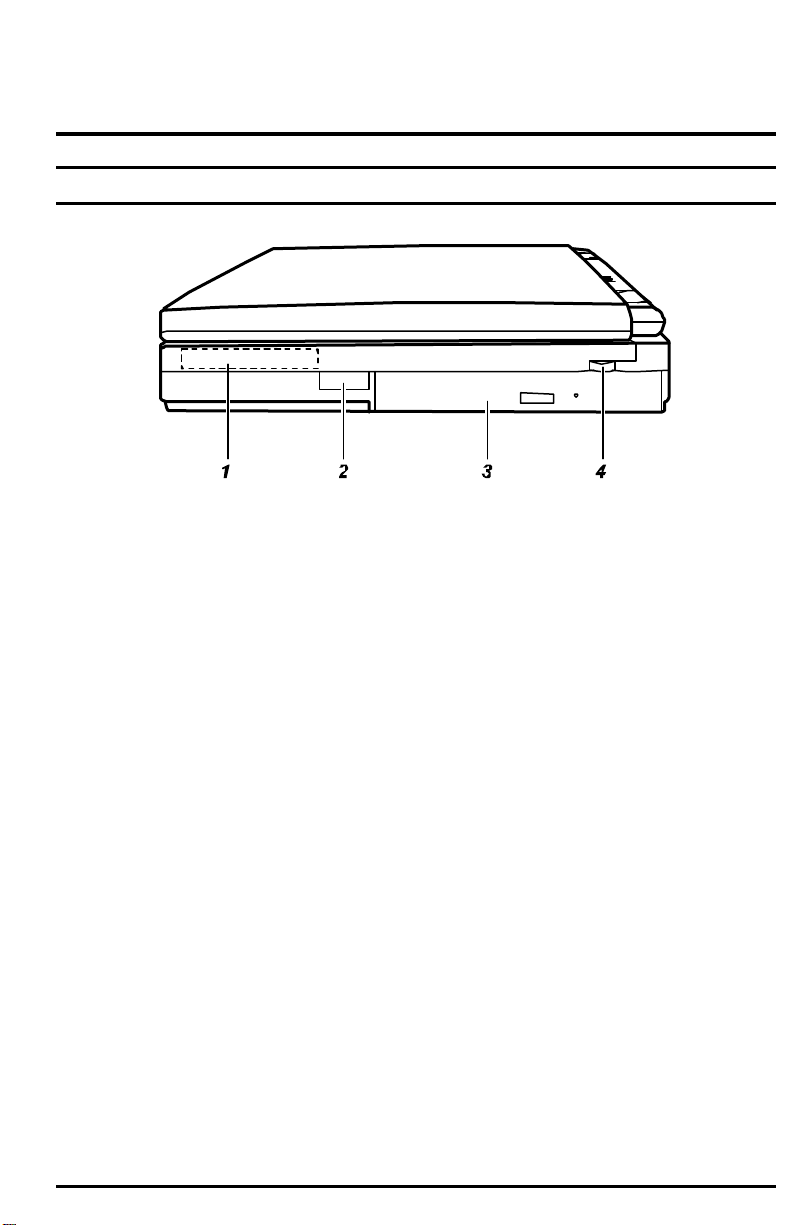
Figure 1-1. Right-Side View
1. Hard Drive
Inside is the hard drive of your notebook, often referred to as drive C. (See
“Hard Drive” in Chapter 2 for more information.)
2. Infrared Port
This infrared port complies with IrDA 1.1 and ASK standards. It allows you to
connect your notebook to an IR device wirelessly. (See “Connecting an
Infrared Device” in Chapter 4 for important notes.)
3. CD-ROM Drive
This is the CD-ROM drive of your notebook, often configured as drive D. (See
“CD-ROM Drive” in Chapter 2 for more information.)
4. Volume Control
This controls the volume of the sound coming from the notebook.
Getting Started 1-3
Page 5
Left-Side View
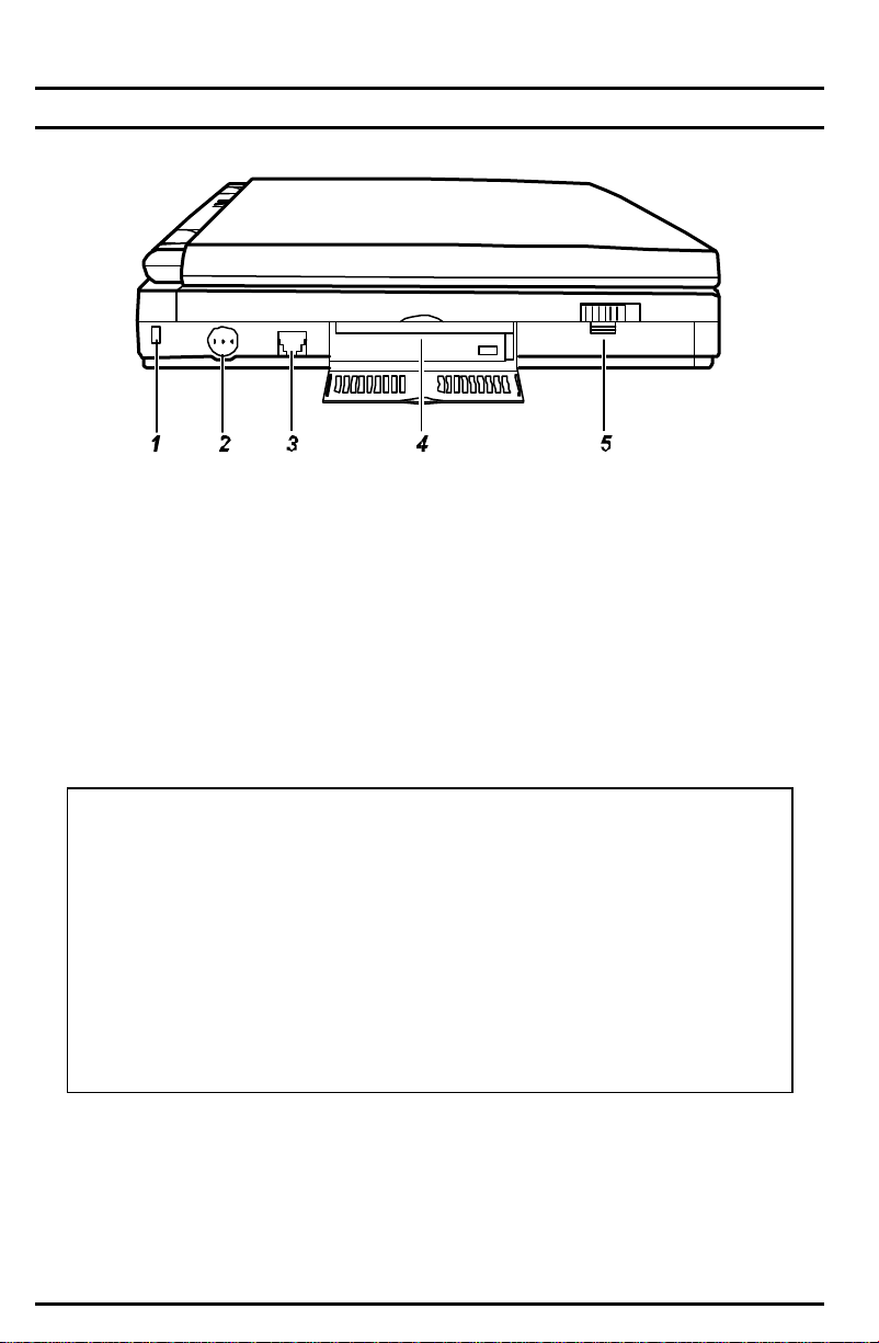
Figure 1-2. Left-Side View
1. Cable Lock Anchor
This rectangular hole can be used as an anchor point for a security cable. Use
a cable to lock your notebook to an appropriate location for security.
2. Power Button
Pressing this button turns the notebook power ON or OFF.
3. RJ-11 Connector (available on select models)
With the RJ-11 connector, the standard telephone line can be connected to
your notebook.
WARNING:
1. Never install telephone wiring during a lightning storm.
2. Never install telephone jacks in wet locations unless the jack is
specifically designed for wet locations.
3. Never touch uninsulated telephone wires or terminals unless the
telephone line has been disconnected at the network interface.
4. Use caution when installing or modifying telephone lines.
5. Avoid using the telephone function during an electrical storm.
There may be a remote risk of electric shock from lightning.
6. Do not use the telephone function to report a gas leak in the vicinity
of the leak.
4. PC Card Slot
Open the display to access the PC Card slot. (See “Installing a PC Card” in
Chapter 4 for more information.)
1-4 Getting Started
Page 6
5. Battery Pack
Inside is the battery pack, which supplies power to your notebook when
external power is not connected. (See Chapter 3 for more information.)
Rear View
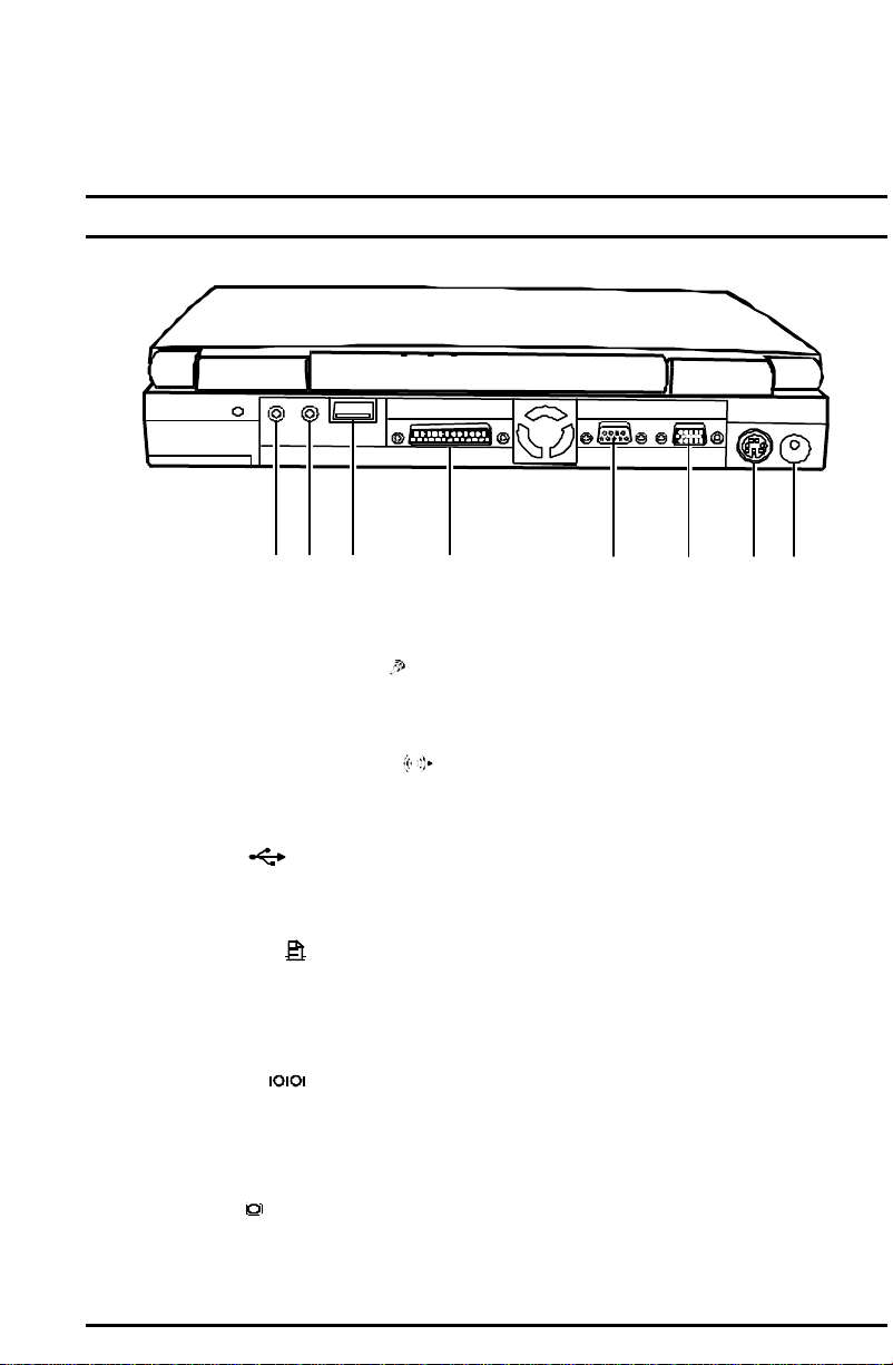
1 2 3 4 5 6 7 8
Figure 1-3. Rear View
1. Microphone Connector ( )
Connects to an external microphone for use in place of the notebook's built-in
microphone.
2. Audio Output Connector (
Connects to a set of headphones, external speakers with amplifier or an audio
recording device.
3. USB Port ( )
The 4-pin Universal Serial Bus port is for connecting an USB device. (See
“Connecting an USB Device” in Chapter 4 for more information.)
4. Parallel Port ( )
This 25-pin port is for connecting a parallel device such as a parallel printer or
pocket LAN. (See “Connecting a Serial or Parallel Device” in Chapter 4 for
more information.)
5. Serial Port ( )
This 9-pin port is for connecting a serial device such as a serial mouse,
modem, or printer. (See “Connecting a Serial or Parallel Device” in Chapter 4
for more information.)
6. VGA Port (
This 15-pin analog port is for connecting an external monitor.
Getting Started 1-5
)
)
Page 7

7. PS/2 Mouse/Keyboard Port ( )
This 6-pin mini-DIN port is for connecting a PS/2 keyboard or mouse.
8. Power Connector ( )
This is for connecting the AC adapter.
1-6 Getting Started
Page 8
Front View
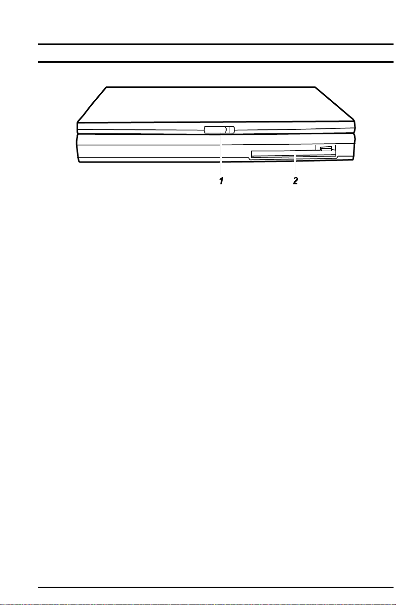
Figure 1-4. Front View
1. Display Latch
The display latch keeps the notebook firmly closed. To open the computer,
press the display latch toward the right, then lift the display.
2. Diskette Drive
This is the 3.5-inch diskette drive of your notebook, often referred as drive A.
(See “Diskette Drive” in Chapter 2 for more information.)
Getting Started 1-7
Page 9
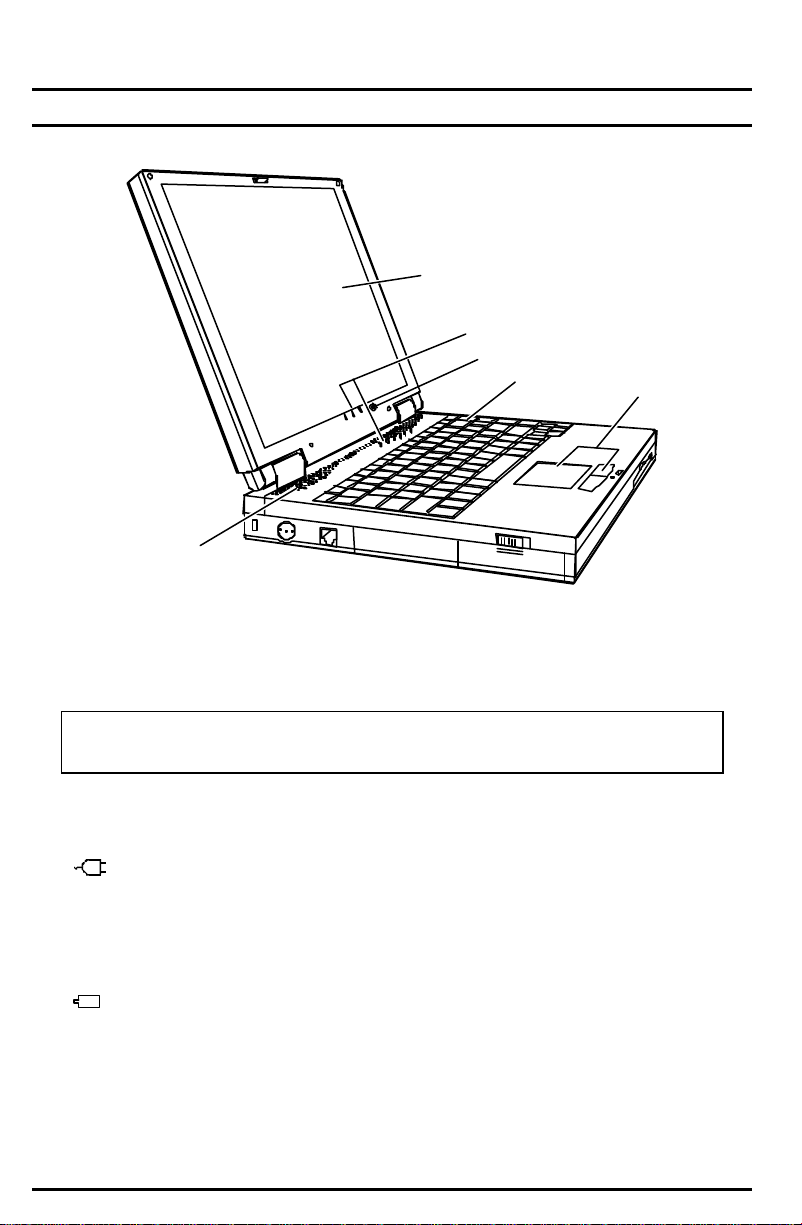
Top-Open View
6
Figure 1-5. Top-Open View
1. Display
This is the display of your notebook.
1
2
3
4
5
CAUTION: Do not place heavy objects on top of the notebook when it is
closed as this can damage the display.
2. Indicators Panel
These are the indicators that show the status of your notebook.
AC Power Indicator
• Turns on when the notebook is using AC power.
• Blinks when the notebook, using AC power, is in Suspend-to-RAM
mode. (See “Introducing Power Management” in Chapter 2 for
information on Suspend-to-RAM mode.)
Battery Power Indicator
• Turns on when the notebook is operating on battery power.
• Blinks when the notebook, using battery power, is in
Suspend-to-RAM mode. (See “Introducing Power Management” in
Chapter 2 for information on Suspend-to-RAM mode.)
1-8 Getting Started
Page 10

Battery Charge Indicator
• Lights green when the battery is fully charged with the AC adapter
connected.
• Lights orange when the battery is being charged.
• Blinks red when the battery is low.
CD-ROM Drive In-use Indicator turns on when the notebook is
accessing the CD-ROM drive.
Hard Drive In-use Indicator turns on when the notebook is accessing
the hard drive.
Diskette Drive In-use Indicator turns on when the notebook is
accessing the diskette drive.
Num Lock Indicator turns on when the Num Lock function is activated.
Caps Lock Indicator turns on when the Caps Lock function is activated.
A
Scroll Lock Indicator turns on when the Scroll Lock function is
activated.
3. Microphone
This is the built-in microphone of your notebook.
4. Keyboard
This keyboard provides all the functions of a full-size 87/90-key keyboard.
(See “Keyboard” in Chapter 2 for information.)
5. TouchPad
This is the pointing device of your notebook. (See “TouchPad” in Chapter 2 for
information.)
6. Stereo Speaker Set
This is the built-in speaker set of your notebook.
Getting Started 1-9
Page 11
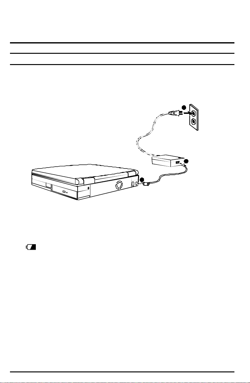
Getting the Notebook Running
Connecting to AC Power
1. Plug the DC cord of the AC adapter into the power connector Ê on the rear of
the notebook.
2. Plug the AC cord Ë into the AC adapter and into the an electrical outletÌ.
3
2
1
Figure 1-6. Connecting the AC Adapter
When the AC adapter is connected, the indicator on the AC adapter lights up,
indicating that power is being supplied from the electrical outlet to the
AC adapter and onto your notebook. When the Battery Charge Indicator
( ) on the notebook glows orange, the AC adapter is charging the battery.
3. To fully charge the battery, leave the notebook power off, and wait until the
Battery Charge Indicator glows green.
When the AC adapter is not connected, you can operate the notebook using
battery power only.
1-10 Getting Started
Page 12

Using Battery Power
When the AC adapter is not connected, you can use battery power. To assure
optimum battery life, fully charge and discharge the battery at least once and then
fully charge the battery before you first use battery power. (For more information
on using battery power, see Chapter 3.)
Starting Up
The notebook starts up with an operating system preinstalled on the hard drive, a
CD-ROM, or a diskette. The notebook will automatically load the operating system
after you turn it on. This process is called booting. Follow these steps to start the
system.
1. Open the notebook by sliding the display latch toward the right and lifting up
the display.
2. Turn on the notebook by pressing the power button (Figure 1-2 #2) on the left
side of the notebook.
3. Tilt the display forward or backward to a comfortable viewing position.
You can also adjust the brightness of the display to attain display clarity.
To adjust brightness, press [Fn]+[F6] or [Fn]+[F7].
4. Each time the notebook is turned on, it performs a Power-On Self Test
(POST). This checks the status of major notebook devices including the
system board, memory, video, keyboard, and disk drive. Some status
messages from POST will appear on the screen.
If the POST has detected a mismatch between the actual hardware
configuration and the configuration information stored in CMOS RAM, you will
see error message(s) prompting you to run the Setup Configuration Utility
(SCU) program. (See Chapter 5 for instructions on running SCU.)
NOTE: The SCU program allows you to enter the configuration
information and store it in CMOS RAM. The configuration information is
needed by the notebook to identify the installed devices. Under SCU, you
can also activate certain features such as Power Saving and Security.
5. When POST successfully completes its check, the notebook first tries to boot
from drive A, C, or CD-ROM depending on the “Boot Sequence” setting in the
SCU program.
Getting Started 1-11
Page 13

NOTE: To avoid viruses brought in by diskettes, boot the system from the
hard disk instead of a diskette. If you must boot up from drive A, make
sure the booting diskette is clean.
Booting with Windows 98
The notebook comes to you with the operating system preinstalled. During the
software installation process, you will be prompted to provide additional
information. To complete the installation process when booting up with
Windows 98 for the first time, follow these steps:
1. When prompted, enter your region, keyboard preference, name, and modem
country/dialing information.
2. If you want to register your copy of the operating system now, connect the
modem cable (included with integrated modem models) to the RJ11 jack on
the notebook and plug the other end of the cable into a standard telephone
wall jack. Then, click Next. If you do not want to register the operating system
at this time click Skip.
3. Review and accept the Microsoft License Agreement, then enter the Product
Key from the Certificate of Authenticity label. The label is located on the
operating system manual or on the bottom side of the notebook. You will not
be able to use the Windows software without entering the Product Key.
4. When prompted, choose the appropriate time zone and set the time and date.
Click Apply, then OK.
5. The system will adjust the final configuration. Click Cancel in response to
device installation dialogs, then allow the system to reboot, if prompted. The
computer is now ready to use.
Your notebook comes with a CD-ROM that contains software drivers you need to
install, thus enabling the special features of your notebook. (See Chapter 6 for
information on the drivers.)
1-12 Getting Started
Page 14

Turning Off the Notebook
CAUTION: Never turn off the notebook when the hard drive In-use
Indicator is on. You may lose your data by doing so.
1. If you are using a program, save your data and exit the program.
2. First make sure all hard drive in-use indicators are off, then remove any
diskette or CD-ROM from the drive.
3. If you are using an operating system such as Microsoft Windows 98 that has
the “Shut Down” command, simply select the command and the notebook will
turn off automatically.
Otherwise, turn off the notebook by pressing the Power Button.
4. Turn off the power to any connected external devices.
5. To close the notebook, tilt down the display until the display latch clicks into
place.
6. To disconnect the AC adapter, unplug it from the electrical outlet first; then
unplug it from the notebook.
Getting Started 1-13
Page 15
Chapter 2
Using the Notebook
This chapter provides operating basics on the notebook’s components such as the
diskette drive, hard drive, CD-ROM drive, keyboard, and TouchPad. It also
introduces power management and gives you tips in care and maintenance.
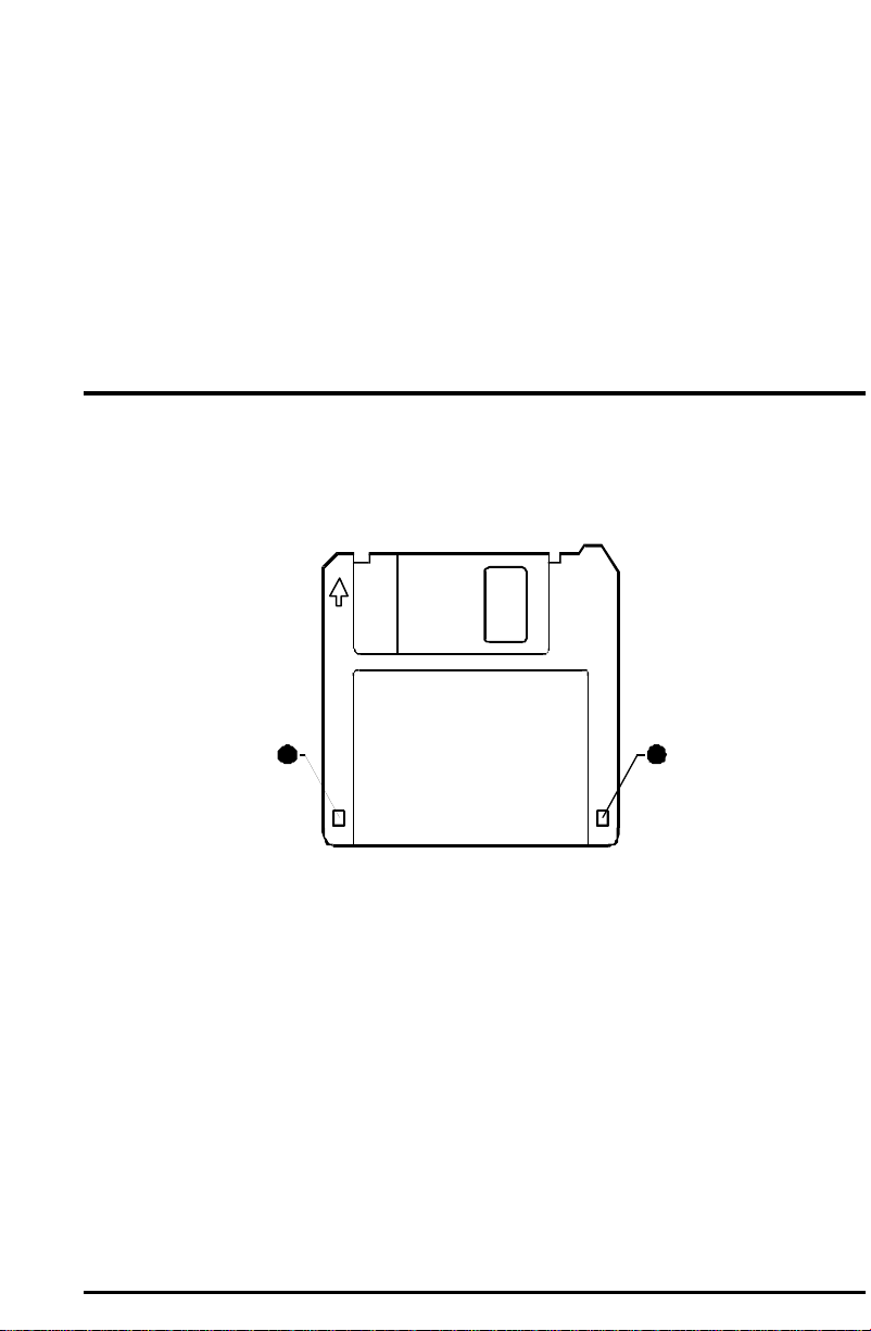
Diskette Drive
Your notebook comes with a diskette drive designated as drive A. A diskette drive
allows you to load new programs into your notebook, or to store data on a
removable diskette so you can transfer data from one notebook to another.
2 1
Figure 2-1. 3.5-inch Diskette
The diskette drive is compatible with either double-density (2DD) 720KB diskettes
or high-density (2HD) Ê 1.44MB diskettes. Notice that both types of diskettes
have an arrow imprinted on the front upper left corner, and a slidable write-protect
tab Ë on the bottom left corner, as illustrated above. When slid downward, the
write-protect tab prevents data from being written to, or erased from, the diskette.
Using the Notebook 2-1
Page 16
Inserting and Ejecting Diskettes
To insert a diskette, hold it with the arrow facing up and towards the drive. Slide
the disk into the drive until it clicks into place.
Figure 2-2. Inserting a Diskette
To eject a diskette, make sure that the diskette drive in-use indicator is off, then
press the eject button on the drive. When the diskette pops out of the drive,
remove the diskette and store it properly.
Formatting Diskettes
A diskette must be formatted before it can store any data. For information on how
to format a diskette, please consult your operating system manual.
CAUTION:
1. Never turn off or reset the notebook while the diskette drive in-use
indicator is on.
2. Always store your diskettes in a safe, clean container, protecting
them from the dust and magnetic fields.
2-2 Using the Notebook
Page 17

Hard Drive
Your notebook comes with a hard drive designated as drive C. A hard drive, also
called a fixed disk, is a storage device with non-removable, rotating, magnetic
storage platters. Compared with a diskette, a hard drive can retrieve and record
data much faster and has a much larger storage capacity.
.
CAUTION:
1. To avoid unexpected data loss caused by viruses or accidents,
regularly backup your files from the hard drive to diskettes.
2. Never turn off or reset the notebook while the hard drive in-use
indicator is on. In addition to possible data loss, the system and the
hard drive’s sensitive circuitry may be damaged.
CD-ROM Drive
Your notebook comes with a CD-ROM drive, which uses removable 5.25-inch
compact disks that look like standard music CD-ROMs. The compact disk is an
ideal medium for data storage or multimedia program because of its huge amount
of data capacity.
Inserting/Removing a CD-ROM
CAUTION:
1. When inserting a CD-ROM, gently insert it into the CD-ROM drive.
2. Make sure the CD-ROM is correctly inserted into the tray, then
close the tray.
3. Do not leave the CD-ROM tray open. Moreover, avoid touching the
lens in the tray with your hand. If the lens becomes dirty, the
CD-ROM may malfunction.
4. Do not wipe the lens with rough surfaced materials (such as paper
towel). Instead, use a cotton swab to wipe the lens gently.
FDA regulations require the following statement for all laser-based
devices:
“Caution, Use of controls or adjustments or performance of procedures
other than those specified herein may result in hazardous radiation
exposure.”
Using the Notebook 2-3
Page 18
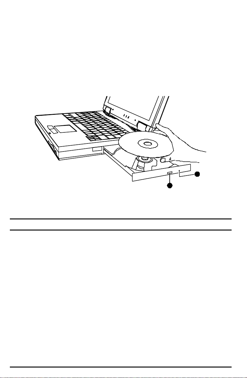
Use the following procedure to insert or remove a CD-ROM.
1. Turn on the notebook.
2. Push the eject button Ê and the CD-ROM tray will slide out. If the tray only
slides out partially, gently pull it until fully extended.
3. To insert a CD-ROM, place the CD-ROM in the tray with its label facing up.
To remove a CD-ROM, hold the disc by its outer edge and lift it up from the
tray
2
1
Figure 2-3. Inserting a CD-ROM
4. Slide the tray back into the drive bay.
Manually Releasing a CD-ROM
In the unlikely event that you are unable to release the CD-ROM tray by pressing
the eject button, you can manually release the tray as follows:
1. Turn off the system.
2. Insert a small rod into the manual eject hole Ë (see Figure 2-3) and push
firmly to release the tray.
3. Pull the tray out until the tray is fully extended, then remove the CD-ROM.
2-4 Using the Notebook
Page 19

Keyboard
Your notebook keyboard has all the functions of a standard AT-enhanced
keyboard plus some keys specific to your notebook.
Function Keys and Hotkeys
On the top row of the keyboard are the function keys: [F1] to [F12] . Function keys
are multi-purpose keys which perform functions defined by individual programs.
Hot key functions are assigned to [Fn]+[F5] through [Fn]+[F12] by your notebook.
Hotkeys refer to a combination of keys that can be pressed at any time to activate
special functions . Most hotkeys operate in a cyclic way. Each time a hot key is
pressed, it shifts the corresponding function to the other or next choice.
The function keys and hotkeys are described below.
Hotkeys Tasks
Fn+F5 toggles between video display output to the notebook display
screen, external monitor, and simultaneous (display on both).
Fn+F6 decrease display brightness.
Fn+F7 increase display brightness.
Fn+F8 decrease display contrast (for non-TFT panel only).
Fn+F9 increase display contrast (for non-TFT panel only).
Fn+F10 toggles between Battery Low Warning beep on and off.
Fn+F11 toggles the display panel on and off.
Fn+F12 activates the “Suspend-to-RAM” or “Suspend-to-Disk” mode
according to the setting of SCU.
Using the Notebook 2-5
Page 20

Special Keys
Several keys are added such as the [Ctrl], [Alt], [Esc], and lock keys for special
purposes. When the lock keys are pressed, their corresponding indicators will
light.
• [Num Lock]
Pressing this key toggles the Num Lock on and off. When on, the Num Lock
activates the numeric keys.
• [Scroll Lock]
Pressing this key toggles Scroll Lock on and off. The Scroll Lock is defined by
individual programs.
• [Caps Lock]
Pressing this key toggles the Caps Lock on and off. When on, the Caps Lock
keeps the letter keys in uppercase.
Numeric Keypad
A 15-key numeric keypad is embedded in the keyboard. Numeric keys facilitate
entering of numbers and calculations . When Num Lock is on, the numeric keys
are activated, meaning you can use these keys to enter numerals.
NOTE:
1. When the numeric keypad is activated and you want to type the
English letter, you can either turn Num Lock off or hold down [Fn]
and press the key without turning Num Lock off.
2. If the “Keyboard Numlock” option in the Setup Configuration Utility
(SCU) program is checked, you can not directly use the alpha keys
on the notebook keyboard. To use the alpha keys, hold down the
[Fn] key first or press the Num Lock key.
3. Some software may not be able to use the numeric keypad on the
notebook. If so, use the numeric keypad on an external keyboard
instead.
Cursor-Control Keys
At the lower right corner of the keyboard are four cursor-control keys: [↑], [↓],
[←], and [→].These keys, also called arrow keys, control cursor movement. On
the right side of the keyboard are [Home], [PgUp], [PgDn], and [End] keys, which
control the screen or cursor movement.
Left to the arrow keys are the [Ins] and [Del] keys used for editing purposes.
2-6 Using the Notebook
Page 21

Windows 95 Keys
On the Windows 95 keyboard, you can find one Windows Logo key ( ÿ ) and one
Application Logo key ( ). The two keys are used with other keys to perform
software-specific functions . (See your Microsoft operating system manual.)
Fn Key
The [Fn] key, at the lower left corner of the keyboard, is used with other keys to
perform alternative functions.
Using the Notebook 2-7
Page 22

TouchPad
Your notebook integrates a TouchPad pointing device, compatible with the
Microsoft Mouse and PS/2-type mouse, which allows you to take advantage of
software that requires or recognizes a pointing device.
Figure 2-4. The TouchPad
Using the TouchPad
Placing and Moving the Finger
To use the TouchPad, place your thumb or forefinger on the TouchPad. The
rectangular pad acts like a miniature duplicate of your display . As you slide your
fingertip across the pad, the pointer, or cursor, on the screen moves in the same
direction across the screen as your fingertip moves across the pad.
Point and Click
When you have placed the cursor over the icon, menu item or command that you
want to execute, you can press the left button once or twice to execute the
command. This procedure is called “Point and click” or “point and double-click”.
On the TouchPad, you can execute pointing and clicking even more rapidly.
Instead of clicking by pressing the left button, gently tap anywhere on the
rectangular pad of the TouchPad. To double-click, rapidly tap twice. Unlike a
traditionally pointing device, the whole pad acts as if it were a left button and each
tap on the pad is equivalent to pressing the left button.
NOTE: If you swap the left and right buttons, “tapping” on the TouchPad
as an alternative method of pressing the left button will no longer be valid.
2-8 Using the Notebook
Page 23

Drag and Drop
You can execute commands or move files by using “drag and drop”. In drag and
drop, you activate a file by pointing to it and clicking. However, when you click the
button, you do not release the button but instead hold it down. You can then drag
the active file around the screen by moving your finger around the pad. When you
have placed the file where you want it, for example in a new directory, release the
left button. The file will drop into the new location. You can also do drag and drop
operations using the TouchPad as a large left button. Position the cursor over the
item that you want to drag. Gently tap twice on the pad. On the second tap, keep
your finger in contact with the pad. You can then drag the selected object around
the screen by moving your fingertip across the pad. When you lift your fingertip
from the pad, the selected object will drop into place.
Changing the Configuration
You may want to customize the mouse. For example, if you are a left -handed
user, you can swap the buttons over so that you can use the right button to
generate events that are normally generated by the left button. You can also
change the size of the on-screen pointer, the speed of the pointer and so on.
To swap buttons or change the size of the pointer in Windows, double-click the
“Mouse” icon in the Windows Control Panel. The Mouse Properties window allows
you to change various configurations . Instead of Windows, you can also use the
TouchPad software supplied with your notebook to change the configuration.
Introducing Power Management
The Power Management feature of your notebook helps conserve power. The
followings briefly describe the features . To establish Power Management, run the
Setup Configuration Utility (SCU) program. (See “Power Menu” in Chapter 5 for
instructions.)
Automatic Power Management
Local Power Management
Local Power Management controls notebook subsystems. When a subsystem is
inactive for a period of time, called “time-out,” it is automatically shut down or
slowed down to reduce power consumption. The subsystem will be active again
when next accessed.
The subsystems under power management are:
•• Hard Drive
•• Display Panel
The above components will power down after the pre-set timing.
Using the Notebook 2-9
Page 24

Global Power Management
Global Power Management automatically puts the notebook into suspend mode
when the notebook is inactive for a period of time, called “time-out.” The notebook
will wake up whenever an activity is detected (e.g. pressing a key).
The time-out settings for suspend mode can be set up in the Setup Configuration
Utility (SCU) program. The notebook suspends to RAM (memory) or disk (hard
drive) depending on the “Suspend Controls” setting in the SCU program.
Manual Power Management
You can manually initiate Suspend mode at any time in one of these ways:
• By pressing the hotkey [Fn]+[F12].
• By closing the notebook.
Note that this works only if the “Lid Switch Function” item is set to
Suspend/Resume in the SCU program.
For information on Suspend-to-Disk mode, see the following section.
Suspend-to-Disk
CAUTION:
1. The suspend-to-disk partition is present on your hard drive when
the computer is shipped. To verify that the suspend-to-disk feature
is available, enable it in the SCU program and reboot the notebook.
If it is not available, you will get an error message and the
suspend-to-disk feature can not be used.
2. The HIBERNAT utility allows you to create the
suspend-to-disk partition. (See “HIBERNAT Utility”
in Chapter 6 for information.)
When the notebook suspends to disk, the system preserves all the running
application programs as a file in a “suspend-to-disk partition” on the hard disk. The
notebook then automatically turns off. The next time you turn on the notebook, it
reads the file from the suspend-to-disk partition back into memory, so that your
notebook is returned to exactly the same state it was in when you suspended it.
Suspend-to-Disk is a very useful feature. People frequently open many
applications when they use notebooks. It takes some time to get all these
applications open and running, and normally they all have to be closed before the
system can be turned off. If you use the Suspend-to-Disk feature, you don’t have
to close the applications as the state of your notebook is saved to disk. When you
turn on your notebook next time, your notebook with all the applications open will
be recreated in just a few seconds.
2-10 Using the Notebook
Page 25

Taking Care of Your Notebook
Maintenance
• Avoid placing the notebook in a location subject to high humidity, extreme
temperatures, mechanical vibration, direct sunlight, or heavy dust.
• Do not place heavy objects on top of the notebook when it is closed as this
may damage the LCD.
• To assure smooth operation of the TouchPad, occasionally clean the pad by
using adhesive tape to remove the dust and grease on its surface.
• Occasionally clean the notebook with a soft cloth moistened with water. Do
not use soap or liquid cleaners on the display.
• Take care of the battery pack by following the instructions described in
“Important Notes on Using Battery Pack” in Chapter 3.
Traveling
• Before traveling with your notebook, it is recommended that you backup your
hard disk data into diskettes . As a precautionary measure, bring along an
extra copy of your hard disk data.
• Make sure the battery pack is fully charged.
• Make sure the notebook is turned off and the top cover is firmly closed.
• Disconnect the AC adapter from the notebook, and take it with you. Use the
AC adapter as the power source and as a battery-recharger.
• Allow extra time for airport security. Many airports inspect electronic devices
carefully.
• Hand-carry the notebook . Do not check it in as luggage.
• If you plan to travel abroad with your notebook, consult your dealer for the
appropriate AC power cord fitting the electricity standard of your destination.
Using the Notebook 2-11
Page 26

Chapter 3
Battery Operations
This chapter provides information on using the battery to get optimal performance
when operating your notebook on battery power.
AC Adapter
CAUTION:
1. The AC adapter is designed for use with your notebook only.
Connecting the AC adapter to another device can damage the
adapter.
2. The AC power cord supplied with your notebook is for use in the
country where you purchased your notebook. If you plan to go
overseas with the notebook, consult your dealer for the appropriate
power cord.
The AC adapter serves as a converter from AC (Alternating Current) to DC (Direct
Current) power because your notebook runs on DC power, but an electrical outlet
usually provides AC power. It operates in the range of
100∼240V AC.
The battery pack automatically recharges while your notebook is connected to AC
power.
Battery Operations 3-1
Page 27

Battery Pack
The battery pack supplies power to your notebook when external power is not
available. It is rechargeable using the AC adapter.
Recharging the Battery Pack
To recharge the battery pack, connect the AC adapter to the notebook and an
electrical outlet. For NiMH batteries, it takes up to 2 hours to fully-charge a powerdepleted battery pack when the notebook power is off, and up to 3 hours when the
notebook is turned on. For Li-ion batteries, it takes up to 2.5 hours to fully-charge
the battery pack with the notebook turned off, and up to 4 hours when the
notebook is turned on.
During recharging, the Battery Charge Indicator ( ) on the notebook glows
orange. You are advised to keep the notebook power off while the battery is being
recharged. The battery is fully recharged when the green Battery Charge Indicator
turns on.
Replacing the Battery Pack
WARNING: There is danger of explosion if the battery is incorrectly
replaced. Replace the battery only with the notebook manufacturer’s
optional battery packs. Discard used batteries according to the dealer’s
instructions.
If you often use the battery power for a long period of time while traveling, you may
consider the purchase of an additional battery pack from your dealer, and keep it
with you in a fully charged state as a backup.
To replace the battery pack, follow these steps:
1. Make sure the notebook is not turned on or connected to AC power.
2. Turn the notebook bottom side up.
3-2 Battery Operations
Page 28

3. First push away the small locking latch (Figure 3-1 Œ) on the battery pack,
then slide the locking latch (Figure 3-1 •) on the side of the notebook to
unlock and lift (Figure 3-1 Ž) the battery pack out of the compartment.
Figure 3-1. Removing the Battery Pack
4. Install new battery pack into the compartment. Make sure the release latch is
in the locked position.
Battery Operations 3-3
Page 29

Important Notes on Using a Battery Pack
Recharging and Discharging
• Recharging will not start if the battery’s temperature is below 0°C (32°F) or
above 45°C (113°F) for NiMH batteries and 40°C (104°F) for Li-ion batteries.
Also, during recharging, the recharging will stop if the battery’s temperature
gets above 60°C (140°F). To avoid problems caused by temperatures, make
sure the battery is not too hot before you begin to recharge or discharge the
battery. Follow these general guidelines:
− When the battery is being recharged, keep the notebook power off and
wait until it is fully recharged to achieve the fastest charge times.
− When the battery is fully charged or discharge, allow a brief cooling
interval to maintain the charge capacity and extend the useful life of the
battery.
• During recharging, in order to maintain fuel gauge accuracy, do not disconnect
the AC adapter before the battery has been fully charged.
• After the battery has been fully recharged, do not repeatedly disconnect and
reconnect the AC adapter to charge the battery again. Doing so may damage
the battery pack or reduce its charge capacity and useful life potential.
• Do not leave the battery completely discharged for too long as this may affect
the battery’s performance.
• A DOS utility named “4dischrg.com” is included on your Utility CD-ROM. It is
used to disable all system power saving functions and allow you to calibrate
the battery fuel gauge. Before running this utility, it is important that you save
all files and close all applications.
Problem Solving
• If the difference between the actual operating time of a battery and the
expected operating time is too large, you can fully discharge and recharge the
battery several times to solve the problem.
3-4 Battery Operations
Page 30

Operating and Handling
• Avoid removing the battery pack while it is in use. If you need to replace the
battery pack, make sure you have saved your information and connected the
notebook to AC power.
• Leave the battery pack in place unless you are replacing it. If you remove the
battery pack, keep it away from conductors such as metals and water.
Contact between the conductors and battery pins may cause a short-circuit
and permanent damage to the battery pack.
• To prevent data loss that may be caused by low battery, develop the habit of
frequently saving your data to the hard drive or a diskette.
• Do not attempt to disassemble the battery pack.
Maintaining
• When you install a new battery, fully charge and discharge the battery at least
once and then fully charge the battery before you begin to use the battery
power for the first time.
• Protect your notebook from extremes in temperature. (See “Environmental
Specifications” in Appendix A for temperature range.)
• Do not store fully-charged battery packs in a bulk or in a densely packed
condition, which may cause reduced charge capacity and useful battery life.
Battery Operations 3-5
Page 31

Low Battery Signals and Actions
Low Battery occurs when the battery has approximately 10% of its charge
remaining. The notebook gives warning beeps and the battery charge indicator
( ) blinks red to alert you to take action.
Immediately save your data upon the Low Battery warning. The remaining
operating time depends on how you are using the notebook: if you are using the
audio subsystem, PC Card, hard or diskette drives, the battery may quickly
deplete its charge.
Always respond to the Low Battery warning by suspending your notebook to disk,
turning off the notebook, or connecting the notebook to AC adapter.
If you do not take any action, after two minutes the notebook will automatically
suspend to disk and turn off.
CAUTION:
1. If the suspend-to-disk partition does not exist on your hard drive
or the “Suspend-to-Disk” item is not set in the Setup Configuration
Utility, the notebook will not be able to suspend to disk. The
notebook will continue to beep until you take action or until the
battery runs out of charge.
2. If you are using a flash PC card, do not access the card during low
battery periods. This is because the access may take longer than
the time it takes the battery to run out of charge, thus making your
access unsuccessful.
3. If you fail to save your data when the battery completely runs out of
charge, you will lose your data.
3-6 Battery Operations
Page 32

Chapter 4
System Expansion
This chapter introduces the optional devices for your notebook provide instructions
on how to install some of the devices.
External Connections
Connectors on the rear and side panels of the notebook allow you to connect
external devices. See Figure 1-1 and Figure 1-3 for connector locations and the
descriptions that follow. This section provides notes on using some of the
connectors.
Connecting an External Monitor
If you want the benefits of a larger color display screen, you can connect an
external VGA-compatible monitor to your notebook. Follow these steps to connect
a monitor to your notebook:
1. Make sure that your monitor is configured for analog operation and that the
voltage setting corresponds to that of the electrical outlet. Consult the
monitor’s manual for instructions.
2. Make sure the notebook is not turned on.
3. On the rear of the notebook , plug the monitor’s D-type signal connector to the
notebook’s VGA port, marked as (Figure 1-3 #6).
4. Ensure power is properly connected to the external monitor.
5. To use the monitor, turn on the monitor before turning on the notebook.
6. The monitor should respond by default. If not, you can switch the display to
the monitor by pressing [Fn]+[F5].
Supplied with your notebook are several video utilities and drivers that offer
extended video modes. See Chapter 6 for additional information.
System Expansion 4-1
Page 33

Connecting an External Keyboard
If you want the benefits of a full-size keyboard, you can connect a
PS/2-compatible keyboard to your notebook. When an external keyboard is
connected, you can use both the external keyboard and notebook keyboard at the
same time.
To use an external keyboard, plug the keyboard cable into the PS/2
mouse/keyboard port, marked as
notebook.
(Figure 1-3 #7), on the rear of the
Connecting a Mouse
If you want the benefits of an external mouse, you can connect a PS/2-compatible
mouse or serial mouse to your notebook. When an external mouse is connected,
the internal TouchPad remains functional.
To use a PS/2 mouse, plug the mouse cable into the PS/2 mouse/keyboard port,
marked as
To use a serial mouse, follow these steps:
1. Make sure the “COM Ports” item is set properly in the Setup Configuration
Utility (SCU) program. (See “Components Menu” in Chapter 5 for information.)
2. Make sure the notebook is not turned on or connected to AC power.
(Figure 1-3 #7), on the rear of the notebook.
3. Plug the mouse cable into the serial port, marked as (Figure 1-3 #5) on
the rear of the notebook.
4. Restart (reboot) the notebook, then install the mouse drivers from the
manufacturer or select a compatible driver from the Windows Control Panel by
clicking Start àSettingsàControl PanelàAdd/Remove. Also, it may be
necessary to restart the notebook and/or select a mouse driver from the
Mouse icon in the Control Panel.
4-2 System Expansion
Page 34

Connecting a Serial or Parallel Device
On the rear of the notebook, you can find a serial port (COM1), marked as ,
and a parallel port, marked as . You can connect a serial device such as a
serial mouse or modem, or a parallel device such as parallel printer, respectively.
In addition to following the instructions supplied with the device, take note of the
following:
• To use a serial device, make sure the “COM Ports” item is set properly in the
SCU program. (See “Components Menu” in Chapter 5 for information.)
• To use a bi-directional or ECP/EPP-compliant parallel device, make sure that
the “LPT Port” item is set accordingly in the SCU program. (See “Components
Menu” in Chapter 5 for information.)
• Portable modems, which are powered by serial or parallel ports, cannot be
used with your notebook. Instead, use a modem which is powered by its own
internal battery or external AC power.
Connecting an Infrared (IR )Device
The IR port (Figure 1-1 #2) on the right side of the notebook allows you to connect
an IR device for wireless communications.
In addition to following the instructions supplied with the device, take note of the
following:
• The IR port of the device to be connected must face the IR port of the
notebook within the effective range, i.e. within ±15-degrees angle and 1-meter
distance.
• Make sure the “COM Ports” and “Ir Mode” items are set properly in the SCU
program. (See “Components Menu” in Chapter 5 for information.)
• To take advantage of the IR communications, you will need third party
software.
Connecting an Universal Serial Bus (USB) Device
The USB port, marked as (Figure 1-3 #3), on the rear of the notebook allows
you to connect an USB device.
The USB is specified to be an industry standard extension to the PC architecture.
It features a wide range of applications such as multiple connections (i.e., support
for concurrent operation of many devices) and compound devices (i.e., peripherals
composed of many functions).
Follow the instructions supplied with the device.
System Expansion 4-3
Page 35

Internal Installation
Installing a PC Card
PC Cards, available in the market, provide various functions. Examples are
memory cards, fax/modem cards, and PCMCIA Type III 1.8-inch hard drive.
Contact your Compaq authorized dealer or reseller for a list of third party PC Cards
qualified for this notebook.
The PC Cards that conform to the PCMCIA 2.1 standard can be used with your
notebook. CardBus is also supported by the PC Card slot.
CardBus provides compatibility with 16-bit PC cards and extends performance and
functionality by adding 32-bit data transfers, and by employing PCI (Peripheral
Component Interconnect) concepts. Typical PC Cards that utilize CardBus are
graphic video, full-motion video, SCSI host bus, and high speed network cards.
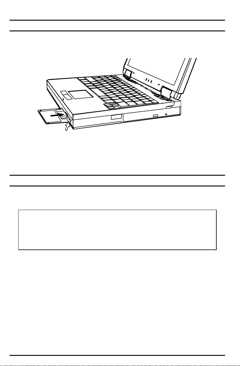
To insert a PC Card:
1. Install the PCMCIA software. (See Chapter 6.)
2. Locate the PC Card slot on the left side of the notebook. Open the display to
access the slot.
3. Slide the PC Card with its label facing up into the slot until the eject button
pops out. (To remove a PC Card, press the eject button.)
Figure 4-1. Installing a PC Card
4-4 System Expansion
Page 36

See the documentation supplied with your PC Card for further instructions.
Notebook Upgrade
You can upgrade your notebook by adding memory for a maximum of 160MB (for
32MB models) or for a maximum of 192MB (for 64-MB models). However, to avoid
damage during the installation procedure, follow the instructions included with the
notebook or consult your Compaq authorized dealer or reseller for help.
System Expansion 4-5
Page 37

Chapter 5
Setup Configuration Utility
This chapter provide instructions on how to configure your system using the Setup
Configuration Utility (SCU).
Introduction
The SCU program allows you to configure the system BIOS settings. Those
settings are vital for your notebook to identify the types of installed devices as well
as to utilize special features. Typical menu items include date and time, the types
of disk drives, and IDE settings. Special features include power saving and
password settings.
The settings information is stored in the CMOS (Complementary Metal Oxide
Semiconductor) RAM, which is powered by a RTC backup battery.
You may need to run SCU when:
• You see an error message on the screen requesting you to run SCU.
• You want to restore the factory default settings.
• You want to modify some specific settings.
Starting the SCU Program
The SCU program is built into the system board. To run SCU, press [F10] during
system startup. The main SCU screen appears as shown in Figure 5-1.
NOTE:
1. The SCU screen shots shown in this chapter are for your reference
only. The actual items on your notebook may differ.
2. The SCU program may have been updated after the publication of
this manual.
Setup Configuration Utility 5-1
Page 38

Startup Memory Disks Components Power Exit
Floppy Drive A = 1.44 Mb
Floppy Drive B = None CPU Clock = 350 MHz
Hard Drive C = 2067 MB
Hard Drive D = 0 MB
Hard Drive E = 0 MB
Hard Drive F = 0 MB
Serial Port 1 = COM1, 3F8, IRQ 4 Base =
640 KB
Serial Port 2 = COM2, 2F8, IRQ 3 Extended =
56320 KB
Parallel Port = LPT1, Addr 378, IRQ 7 Shadow = 64 KB
Reserved = 320 KB
Total RAM = 57344 KB
Cache (Ext) = 1024 KB
Figure 5-1. Main SCU Screen
The SCU screen is divided into three areas:
• On the top line of the screen is the menu bar, which lists the titles of the
available menus. Each menu title contains a pull-down menu, which displays
items for settings.
• The middle section of the screen displays current settings of the system. If
you open a pull-down menu and select an item that provides multiple options,
a submenu will pop up and let you make further selections.
• The bottom window provides alternative information. Normally it gives the
keyboard/mouse instructions for moving around and making selections. When
a menu item is highlighted, the window will provide more detailed description
of the item.
Moving Around and Making Selections
You must go through two or three levels to complete the setting for an item. In
most cases, there are three levels: menu title, pull-down menu, and submenu.
To move around and make selections, you can use both the TouchPad/mouse and
keyboard.
Using the TouchPad/Mouse
Using the TouchPad or mouse is recommended. It is more straightforward than
using the keyboard.
5-2 Setup Configuration Utility
Page 39

For most items, simply move the pointer with the TouchPad/mouse and left -click
on the intended item. To cancel your selection, click the right button. For some
items, you will need to select with the arrow keys.
Setup Configuration Utility 5-3
Page 40

Using the Keyboard
Keyboard information can be found at the bottom of the screen. You can also use
the shortcut key, which is highlighted in a different color on the screen.
Described below is the general procedure to complete a setting by use of the
keyboard:
1. Select a menu title with the left/right arrow key and press [Enter] to pull down
the menu. You can directly pull down a menu by pressing [Alt] and the
shortcut key.
2. From the pull-down menu, select an item with the up/down arrow key and
press [Enter] to access the submenu or change the setting. The submenu
displays further options that you can select.
3. For most menu items, pressing the [Tab] key will jump from one item to
another, thus allowing you to go through the items quickly. To confirm the
changes you make, press [Enter] or select the OK button. To cancel the
changes, press [Esc] or select the Cancel button.
Startup Menu
The Startup pull-down menu, as shown below, contains some basic configuration
and password settings of the system.
Startup
Date and Time
√√ Fast Boot
Boot Device
Set Admin password
Set User Password
5-4 Setup Configuration Utility
Page 41

The following tables describe in sequence all the items of the Startup menu.
Date and Time
The “Date and Time” item sets the system date and time.
When this item is selected, the submenu will display as shown below.
Day 17 Hour 12
Month 11 Minute 20
Year 1999 Second 01
Fast Boot
The “Fast Boot” item, when enabled, speeds up the booting procedure by
bypassing the memory test.
When this item is selected, no submenu will display. A check mark (√) indicates
Enabled; an underline (_) indicates Disabled.
The default setting is Enabled.
Boot Device
The “Boot Device” item sets the sequence of booting device.
When this item is selected, the submenu will display as shown below.
( ) Hard Disk C ( ••) Hard Disk C ( ) Hard Disk C
( ) CD-ROM Drive ( ) CD-ROM Drive ( ••) CD-ROM Drive
( ••) Diskette A ( ) Diskette A ( ) Diskette A
The default setting is Diskette A Õ CD-ROM Õ Drive Hard Disk C.
NOTE: If you set all booting options to the same device (say, Hard Disk
C), then the notebook will try to boot from that device only.
Setup Configuration Utility 5-5
Page 42

Set Admin Password
This item lets you set up administrator-level password.
When this item is selected, the submenu will display as shown below.
Enter old ADMIN password: . . . . .
Enter new ADMIN password: . . . . .
Verify new ADMIN password: . . . . .
[X] Boot System
[X] Enter SCU
You can directly enter the new password if no password has previously existed. If
a password has been previously set up, you have to enter the correct old
password before setting up a new one. In either case, you have to enter the new
password twice to complete the setting.
NOTE:
1. If you want to clear a previous password, you can enter the old
password and leave the following fields blank.
2. The administrator password is required for booting and entering
SCU, so the “Verify password when…” setting can not be changed.
Set User Password
This item lets you set up user-level password.
When this item is selected, the submenu will display as shown below.
Enter old User password: . . . . .
Enter new User password: . . . . .
Verify new User password: . . . . .
[X] Boot System
[ ] Enter SCU
[ ] Resume System
5-6 Setup Configuration Utility
Page 43

The procedure to set up the user password is the same as “Set Admin Password”.
NOTE:
1. You can not set up the user password unless the administrator
password has been set up.
2. If both the administrator and user passwords are set up, only one
password is required to boot the system.
3. To modify the SCU settings, you have to enter the administrator
password. The user password only allows you to browse the
settings.
4. If the “Resume System” item is checked, the password is required
only when the system is restored from “Suspend-to-disk” status.
5. When setting the user password, if you do not specify any “Verify
password when…” condition (i.e. no item is checked), the password
will not be set up.
Memory Menu
The Memory pull-down menu, as shown below, allows you to change the settings
for memory usage.
Memory
Cache Systems
Cache Systems
This menu item lets you to enable or disable the usage of the L2 cache memory.
When this item is selected, the submenu will display as shown below.
( ) Disabled
( ••) Enabled
The default setting is Enabled.
Setup Configuration Utility 5-7
Page 44

Disks Menu
The Disks pull-down menu contains settings which configure the diskette drive and
hard drive of your system, as well as a “Virus Alert” option.
Disks
√√ Internal FDC
Diskette Drives
√√ Internal HDC
IDE Settings
_ Virus Alert
The followings describe in sequence all the items of the Disks menu.
Internal FDC
The “Internal FDC” item sets if an internal floppy drive is present.
When this item is selected, no submenu will display. A check mark (√) indicates
Enabled; an underline (_) indicates Disabled.
The default setting is Enabled.
Diskette Drives
This item sets the type of the diskette drive.
When this item is selected, the submenu displays as shown below.
( ) None
( ••) 1.44 Mb
The default setting is 1.44 Mb.
Internal HDC
The “Internal HDC” item sets if an internal hard drive is present.
When this item is selected, no submenu will display. A check mark (√) indicates
Enabled; an underline (_) indicates Disabled.
The default setting is Enabled.
5-8 Setup Configuration Utility
Page 45

IDE Settings
The “IDE Settings” item sets the type of the hard disk drive in your system.
When this item is selected, the submenu will display as shown below.
( ) Standard ( ) Disabled
( ) Fast PIO ( ••) Enabled
( ) Multiword DMA
( ••) Ultra DMA-33/66
( ) Disabled
( ••) Enabled
The “HDD Timing” item sets the fastest allowable data transmit mode of the hard
drive. If data errors occur, use this setting to slow down data transfers . The default
setting is Ultra DMA-33/66.
The “I/O 32 bit transfer” item, if enabled, allows you to have better data transfer
rate. This effect is more noticeable under DOS system. The default setting is
Enabled.
The “HDD Block transfer” item, if enabled, allows you to use hard disk with large
capacity. The default setting is Enabled.
Virus Alert
The “Virus Alert” item, when enabled, gives warning messages if the hard disk
boot sector (partition table) has been changed.
When this item is selected, no submenu will display. A check mark (√) indicates
Enabled; an underline (_) indicates Disabled.
The default setting is Disabled.
NOTE: Enabling the Virus Alert option may cause problems with some
software applications. If a problem is suspected, disable the Virus Alert
option after scanning the application with a trusted virus scan utility and
retry the software.
Setup Configuration Utility 5-9
Page 46

Components Menu
The Components pull-down menu, as shown below, allows you to change the
settings for various components.
Components
COM Ports
LPT Port
√√ Keyboard Numlock
Keyboard Repeat
The followings describe in sequence all the items of the Components menu.
COM Ports
The “COM Ports” item sets the settings of COM Port A and B.
When this item is selected, the submenu will display as shown below.
( ) None ( ••) IrDA (HPSIR)
( ••) COM1, 3F8, IRQ4 ( ) ASK IR
( ) COM2, 2F8, IRQ3
( ) COM3, 3E8, IRQ4
( ) COM4, 2E8, IRQ3
( ) None
( ) COM1, 3F8, IRQ4
( ••) COM2, 2F8, IRQ3
( ) COM3, 3E8, IRQ4
( ) COM4, 2E8, IRQ3
In general, COM A is assigned to RS-232 (the serial port); COM B is assigned to
IR function. You can further select the IR mode in “Mode Setting for COM B” item.
5-10 Setup Configuration Utility
Page 47

LPT Port
The “LPT Port” item sets the settings of LPT port.
When this item is selected, the submenu will display as shown below.
( ) None ( ) Standard AT (Centronics)
( ••) LPT1, Addr 378, IRQ7 ( ) Bidirectional (PS-2)
( ) LPT2, Addr 278, IRQ5 ( ) Enhanced Parallel (EPP)
( ) LPT3, Addr 3BC, IRQ7 ( ••) Extended Capabilities (ECP)
( ) DMA 0
( ) DMA 1
( ••) DMA 3
EPP Type: EPP 1.7
Your system supports EPP (Enhanced Parallel Port) and ECP (Extended
Capabilities Port) standards which turn the standard parallel port into a high speed
bi-directional peripheral port. If you select ECP item, you can further choose which
DMA channel to use.
Keyboard Numlock
The “Keyboard Numlock” item sets if the numeric keypad will function.
NOTE: If you disable this option, you can only activate the numeric
keypad by holding down the [Fn] key first, even when the Num Lock
indicator is on. However, an externally-connected keyboard is not affected
by this feature.
When this item is selected, no submenu will display. A check mark (√) indicates
Enabled; an underline ( _ ) indicates Disabled.
The default setting is Enabled.
Setup Configuration Utility 5-11
Page 48

Keyboard Repeat
The “Keyboard Repeat” item sets the repeat rate and delay time of key strokes.
When this item is selected, the submenu will display as shown below.
( ) 2 cps ( ) 1/4 sec
( ) 6 cps ( ••) 1/2 sec
( ••) 10 cps ( ) 3/4 sec
( ) 15 cps ( ) 1 sec
( ) 20 cps
( ) 30 cps
The “Key Repeat Rate” sets the repeat rate when you hold down a key, while the
“Key Delay” item sets the delaying time between key repeats.
Power Menu
The Power pull-down menu, as shown below, contains the Power Management
settings which help save power.
Power
√√ Enable Power Saving
Timeout Settings
Suspend Controls
_ Ring Resume
Resume Timer
Advance CPU Controls
The followings describe in sequence all the items of the Power menu.
Enable Power Saving
The “Enable Power Saving” item is the master control for the Power Management
features. If this item is disabled, all Power menu items except “Suspend Controls”
will be automatically disabled.
When this item is selected, no submenu will display. A check mark (√) indicates
Enabled; an underline (_) indicates Disabled.
The default setting is Enabled.
Timeout Settings
This item lets you set up the timeout functions for power saving purpose.
5-12 Setup Configuration Utility
Page 49

NOTE: Some operation systems, such as Windows 98, have built-in
APM/ACPI configurations which could possibly override these settings.
When this item is selected, the submenu will display as shown below.
Video Timeout: Always On
Disk Timeout: 1.0 Min
Global Timeout: 1 Min
Monitor Video Activity: Disabled
Suspend Timeout: Never
Suspend-to-disk: Never
The followings describe in sequence all the items of this submenu.
Video Timeout
The “Video Timeout” item sets the time-out period for the monitor to power down if
it is not in use during the set period. The monitor will power up again when any
key is pressed.
The available options are 30 Sec, 2 Min, 5 Min, 10 Min, 15 Min, and Always On.
Disk Timeout
The “Disk Timeout” item sets the time-out period for the hard drive to power down if
it is not in use during the set period. The hard disk will power up again when next
accessed.
The available options are 30 Sec, 1 Min, 1.5 Min, 2 Min, and Always On.
Global Timeout
The “Global Timeout” item sets the time-out period for the whole system to power
down if it is not in use during the set period. The system will power up again when
any key is pressed.
The available options are 1 Min, 2 Min, 4 Min, 6 Min, 8 Min, 12 Min, 16 Min, and
Always On.
Monitor Video Activity
The “Monitor Video Activity” item sets if the video activity will be monitored. If
enabled, any activity on the screen (such as showing a movie title) will prevent the
monitor from powering down.
The available options are Enabled and Disabled.
Setup Configuration Utility 5-13
Page 50

Suspend Timeout
The “Suspend Timeout” item sets the time-out period for the system to enter
suspend mode if it is not in use during the pre-set period.
The Suspend mode is determined by the “Suspend Type” item in the “Suspend
Controls” submenu. It can be Suspend-to-RAM or Suspend-to-Disk.
When Suspend-to-RAM mode is initiated, several subsystems will enter standby
or power-off mode to conserve power. The system will wake up from
Suspend-to-RAM mode when a key is pressed. “Resume Timer” and “Ring
Resume” items, if enabled, can also wake up the system from Suspend-to-RAM
mode.
When Suspend-to-Disk mode is initiated, the system preserves all the running
application programs as a file in a “suspend-to-disk partition” on the hard disk and
then turns off automatically.
The available options are 1 Min, 5 Min, 10 Min, 20 Min, 30 Min, and Never.
Suspend-to-disk
The “Suspend-to-disk” item sets the time-out period for the system to enter
suspend-to-disk mode if it is not in use during the set period.
When Suspend-to-Disk mode is initiated, the system preserves all the running
application programs as a file in a “suspend-to-disk partition” on the hard disk and
then turns off automatically.
The available options are 1 Min, 5 Min, 10 Min, 20 Min, 30 Min, and Never.
NOTE: This item functions regardless of the “Suspend Timeout” setting
and the “Suspend Type” setting in the “Suspend Controls” submenu. If the
timing of this item is shorter than that of “Suspend Timeout”, the system
will directly enter Suspend-to-disk mode if staying inactive for the timing.
5-14 Setup Configuration Utility
Page 51

Suspend Controls
The “Suspend Controls” item lets you micromanage several suspend features.
When this item is selected, the submenu will display as shown below.
Power Button Function: Power On/Off
Lid Switch Function: Blank LCD
( ) Suspend To Disk
( ••) Suspend To RAM
The followings describe in sequence all the items of this submenu.
Power Button Function
This item sets the function of the power button. The available options are Power
On/Off and Suspend/Resume.
NOTE: When this item is set to “Suspend/Resume”, you can turn off the
power by pressing the button for 5 seconds.
Lid Switch Function
This item sets the sequential event when the top cover is closed while power is on.
The available options are Blank LCD and Suspend/Resume.
Suspend Type
This item sets the suspend mode the system will enter if it stays inactive for the
timing set in the “Suspend Timeout” item (see “Suspend Timeout” in “Timeout
Settings” menu). The available options are Suspend To Disk and Suspend To
RAM.
Ring Resume
The “Ring Resume” item enables or disables the system’s waking up from
Suspend-to-RAM mode when the modem receives an incoming call.
When this item is selected, no submenu will display. A check mark (√) indicates
Enabled; an underline (_) indicates Disabled.
The default setting is Disabled.
Setup Configuration Utility 5-15
Page 52

Resume Timer
The “Resume Timer” item sets the date and time the system will resume from
suspend mode.
When this item is selected, the submenu will display as shown below.
Alarm Resume: Disabled
Resume Month 8
Resume Day 8
Resume Hour 12
Resume Minute 0
The default setting is Disabled.
Advance CPU Controls
This item lets you further set up advanced CPU functions.
When this item is selected, the submenu will display as shown below.
Clock Control Mechanism: 56.25-62.5%
Clock Run Enable: Enabled
The followings describe in sequence all the items of this submenu.
Clock Control Mechanism
This item sets the CPU activity under normal condition. The available options
range from 6% to full speed (Disabled). Note that although this item sets the
usage of CPU resource, the CPU can still reach its full speed if the system is
under a heavy job load.
The default setting is Disabled.
Clock Run Enable
This item sets if the system can take advantage of the southbridge chipset to help
data transmit, thus reducing the job load of the CPU
The default setting is Enabled.
5-16 Setup Configuration Utility
Page 53

Exit Menu
The Exit pull-down menu, as shown below, displays ways of exiting SCU. After
finished with your settings, you must save and exit SCU so that the settings can
take effect.
Exit
Save and Reboot
Exit (No Save)
Default Settings
Restore Settings
Version Info
Descriptions of the Exit choices are:
Choices Descriptions
Save and Reboot Save changes and reboot the system.
Exit (No Save) Exit without saving the changes you have made.
Default Settings Load factory default values for all the items.
Restore Settings Restore previous values for all the items.
Version Info Show BIOS version information.
Setup Configuration Utility 5-17
Page 54

Chapter 6
Software Drivers and Utilities
This chapter provides installation instructions on required drivers and useful
programs for Microsoft Windows 98 and Windows 2000 Professional systems.
Descriptions of available options are also provided, so that you can utilize the
feature functions of your notebook.
NOTE:
1. The Utility CD-ROM may have been updated after this manual was
published.
2. README files can always be found on the utility CD-ROM. Refer to
the READEM files together with this manual.
How to Install the Drivers
The utility CD-ROM provides all the drivers you need to get the notebook running.
Read this chapter thoroughly and install all necessary drivers according to your
system.
IMPORTANT: It is highly recommended that you install the drivers in the
sequence as they appear in this chapter, beginning with the chipset driver.
Please note that when a directory is being specified, the CD-ROM drive is always
referred as drive D. The actual condition may differ.
For Microsoft Windows 98 files, specify the path d:\Win98\, then browse the path
to locate the file you need.
For Microsoft Windows 2000 Professional files, specify the path d:\Win2000\, then
browse the path to locate the file you need.
For the latest version of these drivers, go to the Compaq website at
http://www.compaq.com.
Installing the VIA Bridge Driver
This driver allows the notebook to recognize the VIA chipset on the system board.
The functions include Host Bridge, ISA Bridge, USB and power management. To
run the program, specify the file “Setup.exe” under
Software Drivers and Utilities 6-1
Page 55

d:\Win98\Bridge\Via\Setup\setup.exe.” Click on the Setup.exe file and installation
will start. Follow the on-screen instructions.
NOTE: If you are using Windows 2000 Professional, you will not need to
install this driver.
Installing the IRQ Driver
This driver is to ensure better system resource management and that no IRQ
conflict will occur. Click on the “Setup.exe” file and the installation will start.
Follow the on-screen instructions.
NOTE: If you are using Windows 2000 Professional, you will not need to
install this driver.
Installing the AGP Driver
The VIA AGP VxD Driver supports Microsoft AGP software specification Rev 1.5.
To run the program, specify the file “setup.exe” under
d:\Win98\agp\Via\Setup\Setup.exe. Click on the “setup.exe” file and the
installation will start. Follow the on-screen instructions.
NOTE: If you are using Windows 2000 Professional, you will not need to
install this driver.
Installing the VIA VGA Driver
The VGA driver allows your notebook to display vivid images with richer colors.
For Windows 98, follow these installation steps.
1. Right-click on “My Computer” icon and choose “Properties.”
2. Select “Device Manager” tab, unfold the ”Display Adapters” list, and select
the adapter from the list. Click the “Properties” button.
3. Select “Drivers” tab, then press “Update Drivers” button.
4. When prompted, browse to locate the driver,
d:\Win98\Vga\Trident\T842055.inf.
5. Follow the on-screen instructions to complete the installation. When
prompted, restart the notebook.
6-2 Software Drivers and Utilities
Page 56

For Windows 2000 Professional, follow these installation steps:
1. Right-click on “My Computer” icon and choose “Properties.”
2. Click the “Hardware” tab, then select the “Device Manager” tab.
3. Unfold the “Display Adapters” list. Highlight and double-click on the Trident
Video Accelerator CyberBlade-i7 from the list.
4. Select the “Drivers” tab, and click the “Update Drivers” button. Follow the onscreen instructions.
5. When prompted for optional search locations, select “specify a location only,”
then click Next.
6. Browse to d:\Win2000\Vga\Trident\T842055.inf.
7. Follow the on-screen instructions to complete the installation. When
prompted, restart your notebook.
NOTE: According to dual-view specification, you will find two unidentified
monitors on your device list after installing the VGA driver. You have to
manually adjust your monitor type as laptop 1024X786 (13.3" panel) or
800X600 (12.1" panel).
Installing the VIA Audio Driver
The audio driver enables your notebook to produce realistic sound effect.
For Windows 98, follow these installation steps.
1. Right-click on “My Computer” icon and choose “Properties.”
2. Select the “Device Manager” tab, unfold the “Other Devices” list, and select
the PCI Multimedia Audio device from the list. Click the “Properties” button.
3. Select the “Driver” tab, then click the “Update Drivers” button.
4. When prompted, browse to d:\Win98\Audio\Via\Viaudio.inf.
5. Follow the on-screen instructions to complete the installation. Restart the
notebook when installation is complete.
For Windows 2000 Professional, follow these installation steps.
1. Right-click on “My Computer” icon and choose “Properties.”
2. Click on the Hardware tab, then select the “Device Manager” tab.
3. Double-click on “Multimedia Audio Controller,” click the “Driver” tab, then click
on the “Update Driver” button.
Software Drivers and Utilities 6-3
Page 57

4. When prompted for optional search locations, select “specify a location only,”
then click Next.
5. Browse to d:\Win2000\Audio\Via\Viaudio.inf.
6. Follow the on-screen instructions to complete the installation. Restart your
notebook when installation is complete.
Installing the Askey MDC (Modem) Driver
This driver allows you to take advantage of the modem card.
For Windows 98, follow these installation steps.
1. Right-click on “My Computer” icon and choose “Properties.”
2. Select the “Device Manager” tab, unfold the “Other Devices” list, and select
the PCI communication device from the list. Click the “Properties” button.
3. Select the “Driver” tab, then click the “Update Drivers” button.
4. When prompted, browse to d:\Win98\Modem\Askey\mdmchipv.inf.
5. Follow the on-screen instructions to complete the installation.
For Windows 2000 Professional, follow these installation steps.
1. Right-click on “My Computer” icon and choose “Properties.”
2. Click on the Hardware tab, then select the “Device Manager” tab.
3. Double-click on “PCI Simple Communications Controller,” click the “Driver”
tab, then click on the “Update Driver” button.
4. When prompted for optional search locations, select “specify a location only,”
then click Next.
5. Browse to d:\Win2000\Modem\Askey\Mdmchipv.inf.
6. Follow the on-screen instructions to complete the installation. Restart your
notebook when installation is complete.
Installing the VIA 3-Mode Floppy Disk Driver
The “VIA Floppy 3 Mode Disk Driver” supports the following operating systems:
Japanese Windows 98, 4:10.1998
Japanese Windows 2000 Professional
6-4 Software Drivers and Utilities
Page 58

NOTE: Installation of this driver is NOT recommended for non-Japanese
operating systems.
For Windows 98 --> d:\Win98\3mode\Via\Via3mfd.inf
To install under Windows 98:
1. From the Start button, click Settings àControl Panel (otherwise, this can be
achieved by using the right click of My Computer and selecting Properties).
2. Double-click the System icon in the Control Panel
3. Select the Device Manager tab from System Properties.
4. Double-click Floppy Disk Controllers if the floppy disk controllers branch is
not expanded.
5. The default setting is Standard Floppy Disk Controller. Double-click Standard
Floppy Disk Controller. The dialog box appears to display the properties of
driver for the current floppy disk controller. This property sheet now has three
tabs, General, Resources and a new tab, Driver.
6. Select the Driver tab.
NOTE: You will not see Driver tab if you are running Windows 95/98
US version or Japanese NEC 98 version.
7. Click the Change Driver button. This will display the compatible devices. Click
Show all Devices option box will display all three mode drivers that are
available for Windows 95/98.
8. Click Have Disk and point to the point to the d:\Win98\3mode\Via\ directory.
Select "VIA3mfd.inf."
9. To install the 3-mode driver, select "VIA 3-mode Floppy Controller" and click
the Next button.
10. Continue the dialog to complete installation, ignoring any warning messages.
For Windows 2000 (Floppy disk driver)a d:\Win2000\3mode\Via\Via3mfpy.inf
To install under Windows 2000 Professional:
1. Right click “My Computer,” icon and choose “Properties.”
2. Click the “Hardware tab” and select the “Device Manager” button.
3. Double-click "Floppy disk drive", then right-click "Floppy disk drive" and select
“Properties.”
Software Drivers and Utilities 6-5
Page 59

4. Select the “Driver” tab, then click the "Update Drivers” button. Click Next to
begin the installation dialog.
5. Click on Next and select "specify a location.”
6. When prompted for a location, browse to d:\Win2000\3mode\Via\. Click OK.
7. Ensure that "Install one of the drivers" is checked, then click Next.
8. Restart the notebook.
Installing the FIR Driver
1. Verify that IR device is enabled.
2. Press F10 at power-up to enter the System Configuration Utility (SCU).
3. From the Components menu, select COM port. Select "FAST IR" under Mode
Settings for COM B. Click OK, then from the Exit menu, select save and
reboot. Click OK.
To install updated drivers, do the following:
1. From Windows Explorer, click ViewàOptionsàView tab.
2. Under Hidden Files, select Show All Files. Click Apply, then OK.
3. Copy “nscirda.inf” from the Utility CD-ROM d:\Win98\fir directory to the
c:\Windows\Inf directory. This will overwrite the existing files, if needed.
4. Copy “nscirda.sys” from the Utility CD-ROM d:\win98\fir directory to
c:\Windows\System directory. This will overwrite the existing files, if needed.
5. Right click “My Computer “ icon and choose “Properties.”
6. Select the “Device Manager” tab, unfold Network Adapters, and select IRDA
v3.0 Fast Infrared Port device from the list. Click the “Properties” button.
7. Select the “Driver” tab, the click the “Update Drivers” button.
8. When prompted for a location, browse to d:\Win98\Fir.
9. Follow the on-screen instructions to complete the installation. Restart the
notebook when installation is completed.
NOTE: If you are using Windows 2000 Professional, you will not need to
install this driver.
6-6 Software Drivers and Utilities
Page 60

HIBERNAT Utility
NOTE:
Select the suspend-to-disk option in the SCU and reboot the notebook to
find out if the suspend-to-disk partition is already created. If it is not
created or if there is an insufficient size, you will get an error message.
The HIBERNAT.EXE utility program allows you to create the suspend-to-disk
partition in your hard drive, which is required for the Suspend-to-Disk function of
your notebook.
You can locate the file under the \Utility directory on the CD-ROM. To utilize the
program, follow this command syntax:
HIBERNAT -P nn
where nn specifies the size (in MB) of the partition.
You must specify a memory size larger than your current memory size plus 8MB.
The partition, as shipped from the factory, is 206MB to allow for future upgrade of
your memory. Use the command “HIBERNAT -p206” to duplicate the factory
partition size. If you do not specify the parameter, the default size will be your
system RAM plus 8MB. The extra 8MB is for the overhead of the program and
data held in video memory.
You can clear the contents of the partition using the HIBERNAT -C command. The
command is useful only when you are backing up the data in the hard drive.
Software Drivers and Utilities 6-7
Page 61

Appendix A
Specifications
NOTE: The specifications are subject to change without notice.
Notebook, Memory, and Main Components
•• System Processor
AMD K6-2+ series processor
Note: For the latest information on the processor supported by your
notebook, ask your Compaq authorized dealer or reseller.
•• RAM
64MB or 32MB SDRAM on-board, expandable to192 or 160MB with one 3.3V
144pin-DIMM of SDRAM module (model dependent)
• Cache Memory
Internal 128KB L2 (only on models with a K6-2+ processor) on-die cache.
•• ROM BIOS
256KB Flash EEPROM, supporting boot block, video, security, setup, and
power management
•• Display
13.3-inch TFT XGA (1024 x 768) or 12.1-inch HPA or TFT SVGA (800 x 600)
color LCD, integrated power conservation mode
•• Notebook Keyboard
Microsoft Windows compatible keyboard, numeric keypad, 12 function keys, a
special Fn (Function) key
•• Diskette Disk Drive
3.5-inch, 135TPI, double sided, total formatted capacity 1.44MB, with 3 mode
1.2MB support
•• Hard Drive
Enhanced-IDE, 2.5-inch, 5.0-GB, 6.0-GB or higher .
•• CD-ROM Drive
ATAPI IDE 24X CD-ROM
•• TouchPad
Compatible with PS/2 mouse
•• Real-Time Clock/Calendar
128 Bytes, providing system clock, calendar, and configuration information,
stored in CMOS RAM, with battery backup
Specifications A-1
Page 62

Interfaces and Controllers
•• VGA Controller
High performance flat panel CRT/LCD VGA controller, supports TFT/DSTN
LCD panel, AGP 2X mode, up to 1024 x 768 (XGA) resolution
•• Parallel Port
Standard/ECP/EPP parallel communication interface with a DB-25 female
connector
•• Serial Ports
COM1 and COM2 assigned to two of the followings:
− RS-232C communication interface with a 9-pin D-type shell connector
− Fax/Modem Card
− IrDA 1.0/ASK communication interface
•• Auxiliary Device Port
A 6-pin miniature DIN connector for a PS/2-compatible keyboard or mouse
•• PC Card Slots
Compliant with PCMCIA 2.1/JEIDA 4.1 specifications along with
ExCA extension and PC CARD standard, one PC Card slot for one Type I,
Type II or Type III application supporting CardBus
• Audio Subsystem
Supports 3D sound and wavetable capacity, fully compatible with Microsoft
Windows Sound System, legacy compatible with DOS sound system
Power Source
•• AC Adapter
Switched power supply with a separate AC power cord; full range voltage
between 100V ∼240V; frequency 50∼60Hz
Output voltage DC 18.5V - 19.8V, with over-current and overcharging protection
•• Battery Pack
− NiMH, 9 cells, 4/3 AU type, 1.2V per cell (standard)
− Li-ion, 8 cells, UR18650P type, 3.7V per cell (optional)
Environmental Specifications
Temperature Range Relative Humidity
Operating
Storage
A-2 Specifications
0o C (32o F) to 35o C (95o F)
-20oC (-4oF) to 60oC (140o F)
20% to 95% non-condensing
5% to 95% non-condensing
Page 63

Appendix B
Troubleshooting
This appendix is designed to help you find and solve minor problems that you may
encounter using the notebook.
Troubleshooting Approach
The problems that you might encounter can be divided into two basic categories:
hardware and software. Hardware problems can be further divided into being of an
electrical or a mechanical nature. You will know you have a hardware problem if,
for example, the screen is blank, the notebook cannot recognize the disk drives,
or you get an error message during the Power-On Self Test (POST).
Software problems can occur at several levels. Both your operating system and
your software application programs are capable of generating errors and error
messages. If you encounter a software error, try to determine if the error message
is from your operating system or from an application program, and refer to the
appropriate manual for possible remedies.
If you still have a problem after trying all the suggested remedies in this appendix,
contact your Compaq authorized dealer or reseller.
Common Problems
When you encounter a problem, begin by performing a careful visual inspection.
Check the exterior of the notebook first. If no indicators are on, check the battery
charge or electrical outlet, the plug and power cord, and any power switches that
may affect your notebook. If the notebook has been connected to any peripheral
devices, look for loose or disconnected cables.
A few common problems and suggested solutions are presented in the examples
which follow.
Problem: The power button does not function.
• The power button does not respond to a light touch. Press the button firmly.
• If you are using battery power, the battery may be discharged. Connect the
AC adapter.
Troubleshooting B-1
Page 64

Problem: The screen is blank.
• Press the spacebar to see if any power management feature has blanked the
screen to save power.
• If the AC power indicator is not on, check the electrical outlet, the plugs and
power cords.
• If you are using a battery pack, make sure it has a charge remaining, and that
it is installed correctly.
• Check the brightness and contrast controls for your display.
• Reset the notebook by pressing the [Ctrl]+[Alt]+[Delete] keys.
• Turn the notebook off, wait a few seconds, and then turn the notebook back
on.
Problem: Bad pixels appear on the display screen.
• Because of limitations of the LCD technology, bad pixels may appear on the
screen. The inspection standard generally agreed in the LCD industry allows a
maximum of 8 bad pixels on an unit.
Problem: The diskette drive cannot read or write a diskette.
• The diskette is not yet formatted, or could be corrupted.
• If you can’t write to a diskette, the diskette may be write-protected. Check to
ensure that the write-protect tab covers the detection hole.
• If you can’t write to a diskette, the diskette may be full. Use another diskette.
Problem: The message “non-system disk” or “disk error” appears on the screen
after you turn on the system.
• You may have inserted a non-bootable diskette in the diskette drive. Remove
the diskette.
• Check the SCU program to ensure that the drive types are correctly identified.
• If this message is issued when you attempt to boot from your hard disk drive,
insert a bootable diskette and check the integrity of your hard disk drive.
Problem: The date and/or time is incorrect.
• Correct the date and time using the SCU program or your operating system.
• If the date and time are still incorrect, contact your Compaq authorized service
provider to replace the RTC battery.
Problem: The battery cannot be fully recharged.
B-2 Troubleshooting
Page 65

• For safety reasons, several factors can stop the recharging, e.g., when the
battery's temperature gets above 40°C (104°F) or the recharging time exceeds
4 hours. To avoid problems caused by the temperature factor, make sure the
battery does not get too hot. To avoid problems caused by the time factor, you
are advised to keep the notebook power off during recharging. If you use the
notebook during recharging for more than 4 hours, the recharging will stop no
matter whether the battery has been fully recharged or not. If this happens,
you can disconnect and then reconnect the AC adapter to start the recharging
again.
Problem: The battery cannot be recharged.
• Recharging will not start if the battery's temperature is below 0°C (32°F) or
above 40°C (104°F). Make sure the battery's temperature is within the range.
Problem: The PC Card which uses the COM interface does not function.
• The card may be attempting to use COM3 or COM4 ports in a manner that
conflicts with the COM1 or COM2 port being used by another device. You may
be able to resolve the conflict by running the SCU program to change the
COM port settings. If your PC Card uses COM3, set the COM1 part of “COM
Port” item to Disabled. If your PC Card uses COM4, set the COM2 part of the
“COM Port” item to Disabled.
Problem: No sound is produced.
• Confirm the audio driver is installed.
• Check if software-dependent volume control is set too low.
Problem: Distorted sound is produced.
• Ensure the volume control is not set too high or too low. In most cases, high
settings can cause the audio electronics to distort the sound.
Troubleshooting B-3
 Loading...