

Page 1
XC 902 GH DC
Cucina mista
Istruzioni per l'uso e l'installazione
Mixed cooker
Instructions for use and installation
Cuisinière mixte
CH
Instructions pour l'emploi et l'installation
Kombiherd
CH
Gebrauchs- und Installationsanleitungen
Gemengd fornuizen
Instructies voor het gebruik en installeren
Cocina mixta
Instrucciones para el uso y la instalación
Fogão Misto
Instruções para o uso e a instalação
Page 2

AVVERTENZE
La ringraziamo per aver scelto un prodotto Ariston, sicuro e davvero facile da usare. Per conoscerlo, utilizzarlo al meglio e
a lungo, le consigliamo di leggere questo manuale. Grazie.
QUESTE ISTRUZIONI SONO V ALIDE SOLO PER I PAESI DI DESTINAZIONE I CUI SIMBOLI FIGURANO SUL LIBRETTO
E SULLA TARGA MATRICOLA DELL’APPARECCHIO.
1. Questo apparecchio è stato concepito per essere
utilizzato da privati per un uso di tipo non
professionale all’interno di abitazione.
2. Leggere attentamente le avvertenze contenute nel
presente libretto istruzioni, in quanto forniscono
importanti indicazioni riguardanti la sicurezza di
installazione, d’uso e di manutenzione. Conservare
con cura questo libretto per ogni eventuale
consultazione.
3. Dopo aver tolto l’imballaggio assicurarsi dell’integrità
dell’apparecchio. In caso di dubbio non utilizzare
l’apparecchio e rivolgersi a personale professionalmente
qualificato.
4. Alcune parti sono coperte da una pellicola antigraffio
asportabile. Prima di mettere in funzione l’apparecchio,
la pellicola deve essere rimossa e la parte protetta va
pulita con un panno e un prodotto non abrasivo per la
pulizia domestica. Consigliamo, alla prima accensione,
di riscaldare il forno vuoto per circa 30 minuti alla
temperatura massima allo scopo di eliminare eventuali
residui di lavorazione.
5. Non lasciare l’apparecchio inutilmente inserito. Spegnere
l’interruttore generale dell’apparecchio quando lo stesso
non è utilizzato e chiudere il rubinetto del gas.
6. È necessario che tutte le operazioni relative
all’installazione e alla regolazione vengano eseguite da
personale qualificato, secondo le norme in vigore. Le
istruzioni specifiche sono descritte nelle istruzioni
riservate all’installatore.
7. Verificare periodicamente il buono stato del tubo di
collegamento gas e farlo sostituire da personale
qualificato non appena presenta qualche anomalia.
10. Gli accessori del forno che possono venire a contatto
con gli alimenti, sono costruiti con materiali conformi a
quanto prescritto dalla Direttiva CEE 89/109 del 21-1288 e dal D.L. 108 del 25-01-92.
11. Verificare che la portata elettrica dell’impianto e delle
prese di corrente siano adeguate alla potenza massima
dell’apparecchio indicata sulla targhetta. In caso di
dubbio rivolgersi ad una persona professionalmente
qualificata.
12. Alcune parti dell’apparecchio rimangono calde per lungo
tempo dopo l’uso. Fare attenzione a non toccarle.
13. Durante le cotture al forno e al grill, l’apparecchiatura è
sottoposta ad un sensibile riscaldamento in
corrispondenza del cristallo porta forno e parti adiacenti.
Assicurarsi quindi che i bambini non si avvicinino con
l’intento di giocarvi. Desiderando avere una maggiore
sicurezza, presso la ns. Sede Centrale e i ns. Centri
Assistenza Autorizzati (vedi elenco allegato), è
disponibile un dispositivo supplementare di protezione
per i bambini. Per richiederlo, utilizzare la sigla: BAB seguita dal modello dell’apparecchiatura. Il modello
è stampigliato sulla targhetta segnaletica posta sulla
parte posteriore dell’apparecchiatura .
14. Sui bruciatori non devono essere poste pentole instabili
o deformate onde evitare incidenti per rovesciamento.
15. Non utilizzare liquidi infiammabili in vicinanza
dell’apparecchio quando è in uso.
16. Se la cucina viene posta su di un piedistallo, prendere
adeguati accorgimenti affinchè l'apparecchio non scivoli
dal piedistallo stesso.
8. Il cavo di alimentazione ed il tubo di collegamento gas di
questo apparecchio non devono essere sostituiti
dall’utente. In caso di danneggiamento e di eventuale
sostituzione rivolgersi esclusivamente ad un centro di
assistenza tecnica autorizzato.
9. Prima di collegare l’apparecchio accertarsi che i dati della
targhetta caratteristiche (sulla parte posteriore
dell’apparecchio) siano rispondenti a quelli della rete di
distribuzione elettrica e gas.
1
Page 3
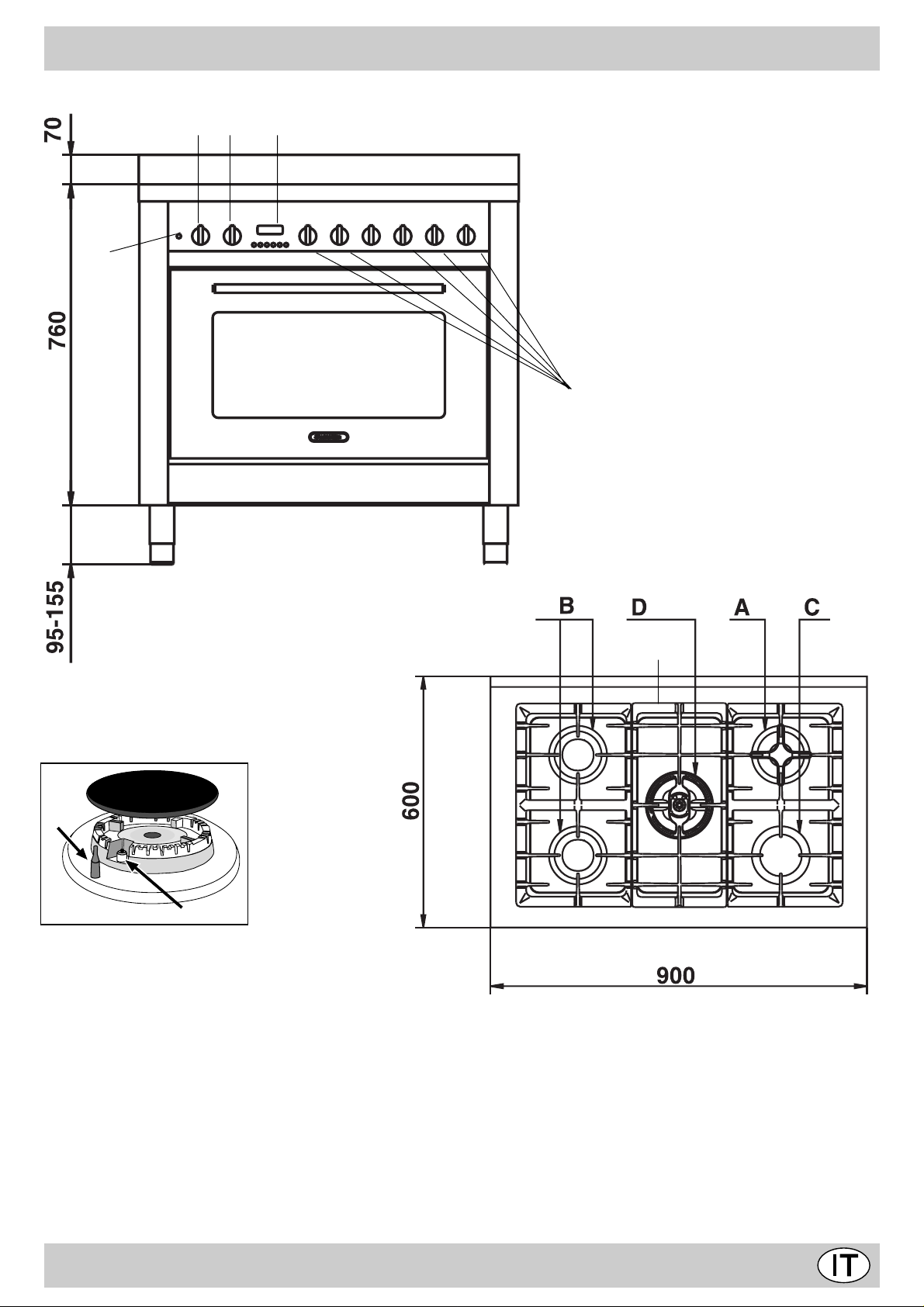
DESCRIZIONE DELLA CUCINA
S
GH
T
M
F
E
A Bruciatore gas ausiliario
B Bruciatore gas semirapido
C Bruciatore gas rapido
D Bruciatore gas DC-DR
R Griglie di supporto per recipienti di cottura
M Manpole di comando dei bruciatori
E Candela di accensione dei bruciatori gas
F Dispositivo di sicurezza - Interviene in caso di spegni-
mento accidentale della fiamma (trabocco di liquidi, correnti d'aria, ...) bloccando l'erogazione del gas al bruciatore.
R
T Timer
S Lampada spia funzionamento forno elettrico
G Manopola commutatore del forno elettrico (selettore
funzioni di cottura)
H Manopola termostato del forno elettrico (selezione
temperature)
2
Page 4
ISTRUZIONI PER L'USO
Bruciatori gas
Sul pannello comandi, intorno ad ogni manopola "M" oppure
sulle manopole stesse, sono indicati i simboli: Rubinetto
Chiuso
Apertura massima
Apertura minima
Inoltre, nelle vicinanze delle manopole i simboli indicano
la posizione sul piano del bruciatore relativo.
I bruciatori sono dotati di sicurezza contro fughe di gas a
termocoppia. Questo dispositivo provvede a bloccare l’uscita
del gas nel caso che la fiamma del bruciatore si spenga
durante il funzionamento.
Per accendere uno dei bruciatori procedere come segue:
• ruotare la manopola corrispondente in senso antiorario fino
al simbolo della fiamma grande;
• premere la manopola a fondo per azionare l’accensione
automatica del gas ;
• mantenere la manopola premuta per circa 10 secondi con
la fiamma accesa per consentire il riscaldamento della
termocoppia di sicurezza;
• rilasciare la manopola, verificando che l’accensione sia
avvenuta in modo stabile. In caso contrario, ripetere
l’operazione.
Per avere la potenza minima ruotare la manopola verso il
simbolo della fiamma piccola. Sono possibili regolazioni
intermedie, posizionando la manopola tra il simbolo di fiamma
grande e quello della fiamma piccola.
erotaicurB)mc(itneipiceRortemaiDø
.AoirailisuA
.BodipaRimeS
.CodipaR
.D)onretni(RD-CDanoroCaippoD
.D)onretse(RD-CDanoroCaippoD
41–6
02–51
62–12
41-01
82-42
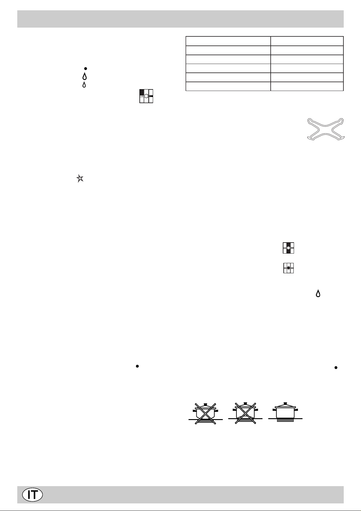
Il piano di cottura è dotato di due griglie di
riduzione (fig.1), le quali vanno usate solo
sul bruciatore ausiliario "A" e sul DC-DR
(interno)"D".
fig.1
Il bruciatore a “doppie fiamme indipendenti”
Questo bruciatore a gas è formato da due fuochi concentrici,
che possono funzionare insieme o in modo indipendente. L’utilizzo contemporaneo al massimo consente un’elevata potenza che riduce i tempi di cottura rispetto ai bruciatori tradizionali. La doppia corona di fiamma, inoltre, rende più uniforme
la distribuzione di calore sul fondo della pentola, in particolare
utilizzando entrambi i bruciatori al minimo. Possono essere
usati contenitori di tutte le dimensioni, in questo caso per piccoli recipienti accendete il solo bruciatore interno. Ogni singola corona che compone il bruciatore a “doppie fiamme indipendenti” ha una sua manopola di comando:
la manopola individuata dal simbolo controlla la corona
esterna;
Importante:
• Non azionare il dispositivo di accensione automatica per
più di 15 secondi consecutivi.
• In alcuni casi la difficoltà di accensione è dovuta ad
eventuale aria che può trovarsi all’interno del condotto del
gas.
• Nel caso di uno spegnimento accidentale della fiamma dei
bruciatori, il gas continua ad uscire per qualche istante
prima che intervenga il dispositivo di sicurezza. Chiudere
la manopola di comando e non ritentare l’accensione per
almeno 1 minuto, lasciando così dileguare il gas uscito
che può essere pericoloso.
• Quando l’apparecchiatura non è in funzione controllare che
le manopole siano in posizione di chiuso " ". Si consiglia
inoltre di chiudere il rubinetto principale del condotto di
alimentazione del gas.
Consigli pratici per l’uso dei bruciatori
Per ottenere dai bruciatori il massimo rendimento si consiglia
adoperare solo pentole di diametro adatto al bruciatore
utilizzato, evitando che la fiamma fuoriesca dal fondo della
pentola (vedi tabella seguente).
Inoltre, quando un liquido inizia a bollire, si consiglia di ridurre
la fiamma quanto basta per mantenere l’ebollizione.
la manopola individuata dal simbolo controlla la corona
interna.
Per accendere la corona desiderata premere a fondo e ruotare
in senso antiorario fino alla posizione di massimo la manopola corrispondente. Il bruciatore è dotato di accensione elet-
tronica che entra in funzione automaticamente premendo la
manopola.
Poichè il bruciatore è dotato di dispositivo di sicurezza
"F", è necessario mantenere premuta la manopola per circa
10 secondi finchè non si scalda il dispositivo che mantiene
automaticamente accesa la fiamma.
Per spegnere il bruciatore occorre ruotare la manopola in
senso orario fino all’arresto (corrispondente al simbolo“ ”).
Al fine di ottenere il massimo rendimento è utile ricordare
quanto segue: Sui bruciatori possono essere utilizzati tutti i
tipi di casseruole. L’importante è che il fondo sia perfettamente piano.
3
Page 5
FORNO MULTIFUNZIONE
FUNZIONAMENTO DEL FORNO ELETTRICO
Il forno offre nove combinazioni diverse delle resistenze
elettriche riscaldanti; scegliendo quella più indicata per il
piatto da cuocere si otterranno risultati molto precisi.
Le varie funzioni si ottengono ruotando la manopola del
selettore “G” nelle seguenti posizioni:
olobmiS enoiznuF aznetoP
0
otnepS)0-
eroirefni+eroirepuseznetsiseR)1W0532
eroirefniaznetsiseR)2W0031
eroirepusaznetsiseR)3W0501
llirG)4W0002
)llirg+eroirepusaznetsiser(llirgixaM)5W0503
erotalitnev+llirgixaM)6W0013
erotalitnev+eroirefniaznetsiseR)7W0531
erotalitnev+eroiretsopaznetsiseR)8W0582
odiparotnemalegnocS)9W05
Dopo aver selezionato la funzione di cottura, posizionare
la manopola del termostato “H” sulla temperatura
desiderata.
• Per cotture normali in modo convenzionale (arrosti,
biscotti, ecc.) utilizzare la funzione (caldo sopra +
sotto).
Introdurre i cibi da cuocere nel forno solo quando questo
ha raggiunto la temperatura selezionata ed utilizzare
preferibilmente un solo ripiano per la cottura.
Desiderando avere un riscaldamento più accentuato nella
parte inferiore o in quella superiore delle pietanze, portare
• La funzione “scongelamento rapido” avviene senza
elementi riscaldanti, utilizzando solo la lampada forno e la
ventilazione.
• La cottura al grill utilizza una potenza riscaldante elevata,
la quale permette una immediata rosolatura superficiale
dei cibi; è particolarmente indicata nel caso delle carni, le
quali devono restare tenere all’interno.
Per effettuare cotture al grill ruotare la manopola del
selettore “H” su una di queste posizioni (grill),
(maxigrill), (maxigrill con ventilazione).
Durante il funzionamento del grill, è necessario
mantenere la porta del forno chiusa. Inoltre,
posizionare la manopola del termostato non oltre i 200
°C.
Illuminazione forno
L’illuminazione all’interno del forno si ottiene
automaticamente ruotando la manopola "H" del selettore
su una qualsiasi delle sue posizioni.
Lampada spia "S"
Indica la fase di riscaldamento del forno; il suo spegnimento
segnala il raggiungimento all’interno del forno della
temperatura impostata con la manopola.
A questo punto l’alternativo accendersi e spegnersi di questa
spia indica che il termostato sta lavorando correttamente
per mantenere costante la temperatura del forno.
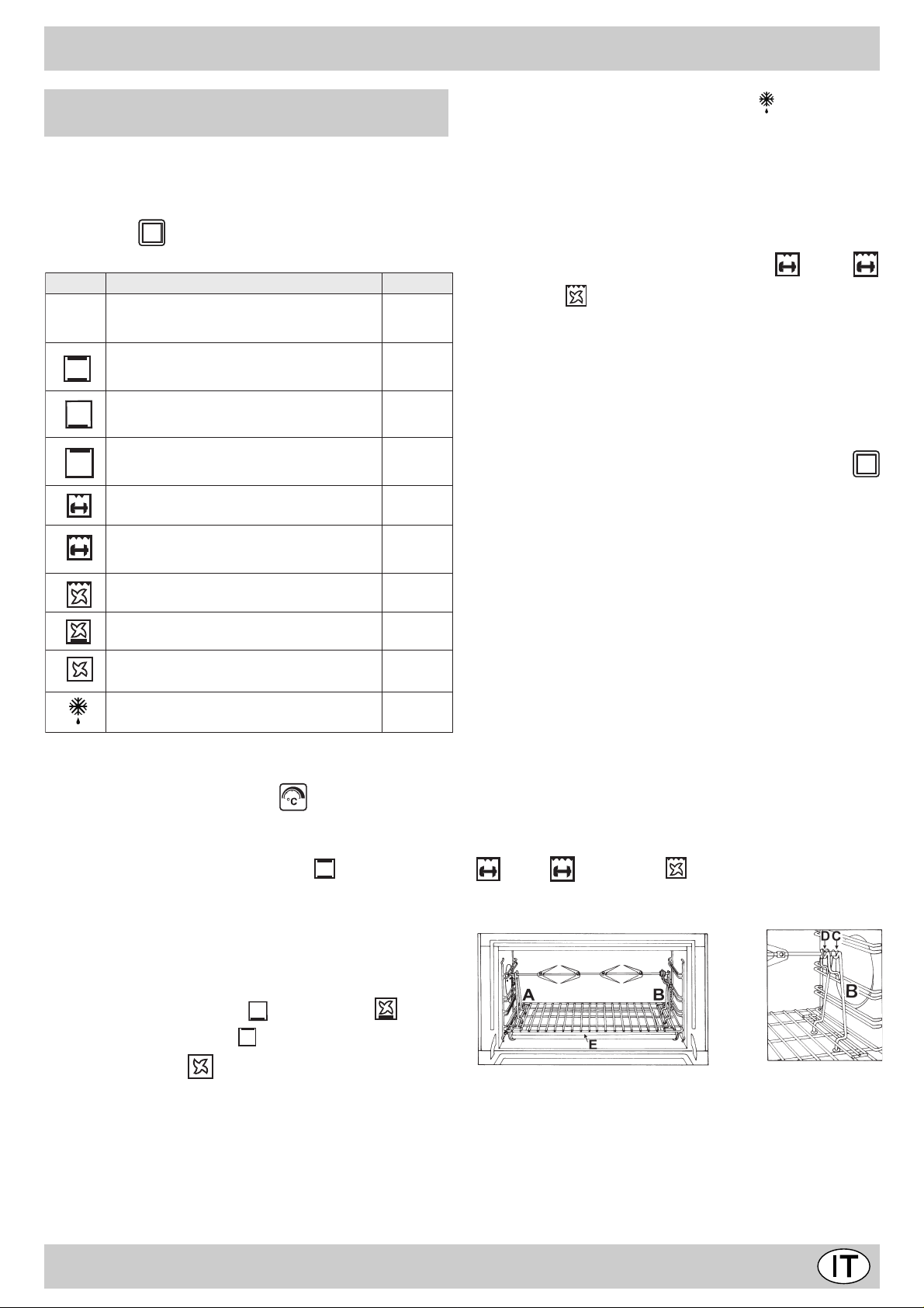
Spiedo - Girarrosto
Questo accessorio è da utilizzare esclusivamente per cotture
al grill. Procedere come segue: infilare la carne da cuocere
nell’asta trasversale, nel senso della sua lunghezza,
bloccandola con le apposite forchette regolabili (fig.2a).
Introdurre i supporti “A” e “B” (fig.2b) nei fori predisposti sulla
leccarda “E”, appoggiare la gola dell’asta sulla sede “C” e
infilare la griglia nella prima guida più bassa del forno; infilare
ora l’asta nel foro del girarrosto, portando in avanti la gola
nella sede “D”. Azionare grill e girarrosto ruotando la
manopola “H” del commutatore nelle posizioni con simbolo
(grill), (maxigrill) o (maxigrill con ventilazione).
il selettore sulla posizione (caldo sotto), (caldo
sotto+ventazione) oppure (caldo sopra).
• Con la funzione (ventilato) la cottura avviene
mediante aria preriscaldata da una resistenza e fatta
circolare all’interno del forno da un ventilatore. Il
riscaldamento del forno è molto rapido, pertanto i cibi da
cuocere possono essere introdotti nel forno anche al
momento dell’accensione. Inoltre, è possibile la cottura
anche su due ripiani contemporaneamente.
fig.2a
fig.2b
4
Page 6
COME TENERLO IN FORMA
Prima di ogni operazione disconnettere l'apparecchio dall'
alimentazione elettrica.
Per una lunga durata del forno è indispensabile eseguire frequentemente una accurata pulizia generale, tenendo presente che:
• le parti smaltate e i pannelli autopulenti (se presenti) vanno lavate con acqua tiepida senza usare polveri abrasive e sostanze corrosive che potrebbero rovinarle;
• l’interno del forno va pulito, preferibilmente ogni volta dopo
l’uso, quando è ancora tiepido usando acqua calda e
detersivo, risciaquando e asciugando poi accuratamente;
• l’acciaio inox può rimanere macchiato se rimane a contatto per lungo tempo con acqua fortemente calcarea o
con detergenti aggressivi (contenenti fosforo). Si consiglia di sciacquare abbondantemente ed asciugare dopo
la pulizia. E’ inoltre opportuno asciugare eventuali trabocchi d’acqua.
• non rivesta mai il fondo forno con fogli di alluminio, poichè
l'accumulo di calore conseguente comprometterebbe la
cottura danneggiando anche lo smalto.
Sostituzione della lampada nel vano forno
• Togliere l’alimentazione al forno tramite l’interruttore
omnipolare utilizzato per il collegamento del forno all’impianto elettrico, o scollegare la spina, se accessibile;
• Svitare il coperchio in vetro del portalampada;
• Svitare la lampada e sostituirla con una resistente ad
alta temperatura (300°C) con queste caratteristiche:
- T ensione 230/240 V
- Potenza 15W
- Attacco E14
• Rimontare il coperchio in vetro e ridate alimentazione al
forno.
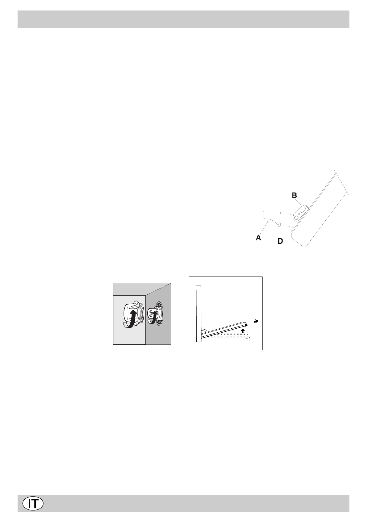
Smontaggio/montaggio della porta del forno
Per facilitare la pulizia all'interno del forno è possibile togliere
la porta del forno, procedendo nel seguente modo (fig.3-4):
• Aprire completamente la porta e alzare le 2 levette "B"
(fig.3);
• Ora, chiudendo parzialmente la porta, è possibile sollevarla estraendo i ganci "A" come indicato in figura 4.
Per rimontare la porta:
• Con la porta in posizione verticale, inserire i 2 ganci "A"
nelle feritoie;
• Assicurarsi che la sede "D" sia agganciata perfettamente
al bordo della feritoia (muovere leggermente la porta avanti
ed indietro);
• Tenere la porta completamente aperta, sganciare le 2
levette "B" verso il basso, quindi chiudere la porta.
fig 3
fig 4
5
Page 7
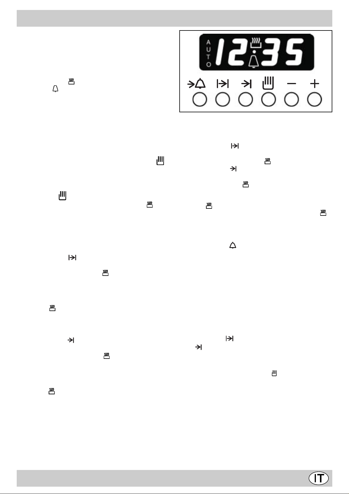
TIMER ELETTRONICO
Il programmatore elettronico ha la funzione di inserire
automaticamente il forno ad un’ora prestabilita e disinserirlo
alla fine del tempo di cottura impostato. Il display luminoso
a 4 cifre indica l’ora del giorno ed i tempi di programmazione,
inoltre visualizza lo stato del forno per mezzo dei seguenti
simboli:
-Forno in funzione
-Contaminuti
-Programma automatico AUTO
-Punto • (divide l’ora dai minuti nel display)
Tutte le funzioni possono essere programmate per un totale
di 23 ore e 59 min.
La durata massima della cottura può essere 10 ore.
Regolazione dell'orologio
(all’atto dell’installazione, per mancanza di corrente, per
anticipi o ritardi)
Selezionare la funzione manuale premendo il tasto e
regolare l’ora con i tasti - e + .
Funzionamento manuale del forno (Programmazione
esclusa)
Premere il tasto ; l’alimentazione elettrica viene riattivata,
si spegne il simbolo AUTO e si accende il simbolo (forno
in funzione) Questa operazione cancella l’eventuale
programma inserito.
Funzionamento semiautomatico del forno
1° caso: inizio cottura manuale - tempo di cottura
programmato.
· Introdurre nel forno i cibi da cuocere.
· Premere il tasto (durata) e regolare la durata della
cottura con i tasti - e + : il forno si inserisce elettricamente,
si illuminano i simboli AUTO e .
· Ruotare le manopole del selettore e del termostato
rispettivamente sulla funzione e sulla temperatura
desiderata per iniziare la cottura.
· Alla fine della cottura il forno si disinserirà elettricamente,
il simbolo (forno in funzione) si spegnerà e il simbolo
AUTO lampeggerà; entrerà in funzione il segnale acustico.
2° caso: inizio cottura manuale - fine cottura programmata.
· Mettere nel forno i cibi da cuocere.
· Premere il tasto (fine cottura) e regolare l’ora di fine
cottura con i tasti - e + ; il forno si inserisce elettricamente,
si illuminano il simboli AUTO e
· Ruotare le manopole del selettore e del termostato
rispettivamente sulla funzione e sulla temperatura
desiderata per iniziare la cottura.
· Alla fine della cottura il forno si disinserirà elettricamente,
il simbolo si spegnerà e il simbolo AUTO lampeggerà;
entrerà in funzione il segnale acustico.
Funzionamento automatico del forno (Durata e fine
cottura programmate)
· Mettere nel forno i cibi da cuocere.
· Premere il tasto (durata) e regolare la durata della
cottura con i tasti - e + : il forno si inserisce elettricamente,
si illuminano i simboli AUTO e .
· Premere il tasto (fine cottura) e regolare l’ora di fine
cottura con i tasti - e + ; il forno si disinserisce elettricamente
e si spegne il simbolo .
· Il programmatore imposta automaticamente l’ora di inizio
della cottura, che viene visualizzata dall’accensione del
simbolo (forno in funzione). Trascorso il tempo di cottura
l’alimentazione elettrica verrà interrotta, il simbolo si
spegnerà e il simbolo AUTO lampeggerà; entrerà in
funzione il segnale acustico.
Contaminuti
Premere il tasto (contaminuti) e regolare il tempo
desiderato con i tasti - e +. Alla fine del programma entrerà
in funzione un segnale acustico.
Segnale acustico
Il segnale acustico suona per 7 minuti dopo la fine del
programma prescelto e può essere disinserito premendo un
tasto funzione qualsiasi.
Sono disponibili 3 tipi di segnale acustico con toni diversi.
Premendo il tasto - è possibile sentire quello attualmente
impostato. Se entro 7 secondi viene premuto ancora il tasto
- si può scegliere un altro segnale acustico.
Controllo del programma
Premere il tasto per conoscere il tempo rimanente, il
tasto per verificare l’ora di fine cottura.
Cancellazione del programma
Il programma si cancella automaticamente una volta
eseguito, oppure premendo il tasto (manuale).
6
Page 8
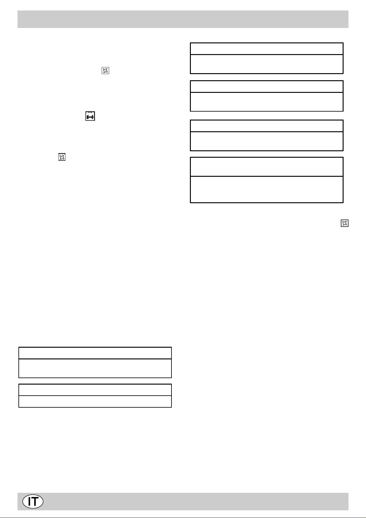
CONSIGLI PRATICI PER LA COTTURA
Preriscaldamento
Nel caso in cui sia necessario preriscaldare il forno, in linea
di massima tutte le volte in cui si cuocciano cibi lievitati, è
possibile utilizzare la funzione “ventilato” che consente
di raggiungere la temperatura desiderata in breve tempo e
con consumi ridotti. Una volta infornato si può passare alla
funzione di cottura più indicata.
Utilizzo del Maxi grill
Utilizzate la posizione “grill” consente una perfetta
grigliatura di piccole porzioni, come toast, wustell etc...
Posizionate il cibo al centro della griglia, dato che risulta
accesa solamente la parte centrale della resistenza superiore, il cibo negli angoli non viene cotto.
La posizione “Maxi grill ventilato” è utilissima per
grigliature veloci, si distribuisce il calore emesso dal grill consentendo contemporaneamente alla doratura superficiale
anche una cottura nella parte inferiore.
Potete anche usarla nella parte finale della cottura dei cibi
che abbiano bisogno di doratura superficiale, ad esempio è
l’ideale per dorare la pasta al forno a fine cottura.
Importante: effettuare la cottura al grill con porta del
forno chiusa, ciò per ottenere unitamente ai migliori risulta-
ti un sensibile risparmio di energia (10% circa).
Desiderando eseguire cotture al grill, si consiglia di regolare
la manopola del termostato al massimo consentito (200°C)
perchè questa è la condizione di rendimento ottimale, che si
basa sull’azzione dei raggi infrarossi; la griglia va disposta
sui ripiani più alti (vedi tabella cottura) e, per raccogliere i
grassi ed evitare la formazione di fumo, disponete la leccarda
nel primo ripiano in basso.
Cottura dei dolci
Nella cottura dei dolci infornate sempre a forno caldo, attendete la fine di preriscaldamento, indicata dallo spegnimento
della spia rossa “S”. Non aprite la porta durante la cottura,
per evitare un abbassamento del dolce.
Gli impasti sbattuti non devono essere troppo fluidi, per non
prolungare troppo i tempi di cottura. In generale:
Dolce tropp o secco
La prossima volta impostate una temperatura di10°C
superiore e ri ducete il tempo di cot tura.
Dolce si abbassa
Usate meno liquido o abbassate la temperatura di 10°C.
Dolce scuro super i orme nt e
Inseritelo ad al tezza i nferior e, impostate una
temperatura più bassa e prolungate la cottura.
Buona cott ur a este rna, ma interno colloso
Usate meno liquido, riducete la temperatura, aumentate
il tempo di cottura.
Dolce non si sta cca dallo stampo
Ungete bene lo stampo e cospargetelo anche con un
pò di farina.
Ho cot to su pi ù ripiani e non tutti sono allo stesso
avanza mento di cot tur a
Impostate una temperatura inferiore.
Non necessariamente ripi ani i nser iti
contemporaneamente debbono essere tolti insieme.
Cottura della pizza
Per una buona cottura della pizza utilizzate la funzione
“ventilato”:
• Preriscaldare il forno per almeno 10 minuti
• Utilizzare una teglia in alluminio leggero appoggiandola
sulla griglia in dotazione. Utilizzando la leccarda si allungano i tempi di cottura e difficilmente si ottiene una
pizza croccante
• Non aprite frequentemente il forno durante la cottura
• Nel caso di pizze molto farcite (capricciosa, quattro stagioni) è consigliabile inserire la mozzarella a metà cottura.
Cottura del pesce e della carne
La carne deve pesare almeno 1 Kg. per evitare che si asciughi troppo. Per le carni bianche, i volatili ed il pesce utilizzate temperature basse (150°C-200°C).
Per le carni rosse che si vuole siano ben cotte all’esterno
conservando all’interno il sugo, è bene iniziare con una temperatura iniziale alta (200°C-220°C) per breve tempo, per
poi diminuirla successivamente.
In generale, più grosso è l’arrosto, più bassa dovrà essere
la temperatura e più lungo il tempo di cottura. Ponete la
carne da cuocere al centro della griglia ed inserite sotto la
griglia la leccarda per raccogliere i grassi. Inserite la griglia
in modo che il cibo si trovi al centro del forno.
Se volete più calore da sotto, utilizzate i ripiani più bassi.
Per ottenere arrosti saporiti (in particolare anitra e selvaggina) bardate la carne con lardo o pancetta e posizionatela
in modo che sia nella parte superiore.
7
Page 9
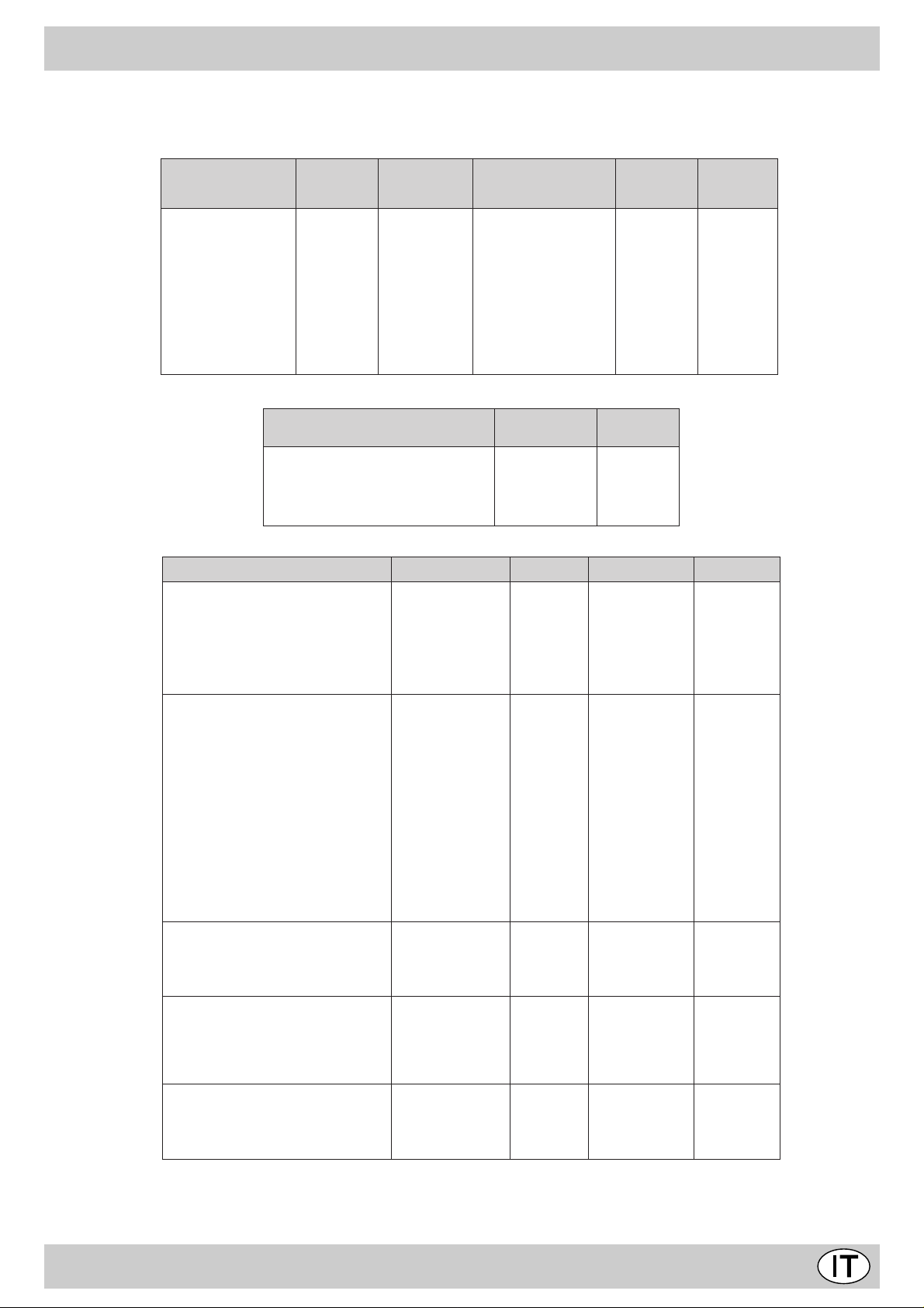
CONSIGLI PRATICI PER LA COTTURA
I tempi di cottura possono variare secondo la natura dei cibi, la loro omogeneità e il loro volume. Alla prima cottura, sceglie re
pertanto i valori del tempo di cottura più bassi tra quelli indicati e successivamente aumentarli se necessario.
Cottura in modo CONVEZIONALE
aznateipidopiT
aireccitsaP
atturfidatroT
ehgnireM
angapSidnaP
olegnA'lledatroT
atirehgramatroT
otaloccoiclaatroT
aiccacoF
èngiB
ailgofsidittocsiB
eilgofelliM
allorfatsaP
arutarepmeT
C°
031
031
051
061
061
071
071
002
002
002
002
idopmeT
aruttoc
)itunim(
07-06
04-03
03-02
05-04
05-04
04-03
05-04
02-51
02-51
02-51
02-51
inraC
Tonihcca).gk8-4(
acO).gk5-4(
artanA).gk4-2(
enoppaC).gk3-½2(
olloP).gk½1-1(
ecseP
aznateipidopiT
otasarbeuB).gk½1-1(
ollengaidottoicsoC
otsorraerpeL).gk2(
otsorraonaigaF
C°
arutarepmeT
061
061
071
071
061
061
061
061
071
002
½4-3
½4-4
½2-2
½3-3
½1-1
½1-1
½1-1
½1-1
Cottura al GRILL
eiccislaS
aznateipidopiT
).gk5.0(eloicarB
idopmeT
)itunim(aruttoc
06
51
)gk1(ailgirgallaolloP
).gk6.0(odeipsollaolletividotsorrA
).gk1(odeipsollaolloP
06
06
06
enoizisoP
ailgirgalled
adiugª3
adiugª2
adiugª1
-
-
La 1ª guida è quella in
posizione più bassa.
Cottura in modo VENTILA TO
aznateipidopiT ossabladadiug.N .gkàtitnauQ C°arutarepmeT itunimopmeT
icloD
opmatsniotuttabsotsapminoC*
opmatsaznesotuttabsotsapminoC*
atrotodnofallorfatsaP
odimuoneipirnocallorfatsaP
occesoneipirnocallorfatsaP
elarutanenoizativeilaotsapminoC*
iclodilocciP
enraC
ailgirgusittocitsorrA
olletiV
oznaM
eselgni'llafeebtsaoR
elaiaM
olloP
ailgetusittocitsorrA
olletiV
oznaM
elaiaM
olloP
icnartnionihccaT
artanA
ittocartS
oznamidottocartS
olletividottocartS
icseP
ollesan,ozzulrem,ehccetsib,itteliF
aloilgos
inomlas,obmor,orbmogS
ehcirtsO
itamrofS
attuicsatsapidotamrofS
arudrevidotamrofS
italaseiclodseèlffuoS*
enozlaceazziP*
tsaoT
otnemalegnocS
itnorpittaiP
enraC
enraC
enraC
Note:
1) Le cotture sono intese senza preriscaldamento del forno ad eccezione di quelle contrassegnate con l’asterisco.
2) L’indicazione per l’uso dei gradini data nella tabella è quella preferenziale nel caso di cottura su più livelli.
3) I tempi dati si riferiscono alla cottura su un solo ripiano, per più livelli aumentare i tempi di 5÷10 minuti.
4) Per gli arrosti di carne di manzo, vitello, maiale e tacchino con osso o arrotolati aumentare i tempi di 20 minuti.
3-1
4-3-1
4-3-1
3-1
4-3-1
3-1
4-3-1
2
2
2
2
2
3-1
3-1
3-1
3-1
3-1
3-1
1
1
3-1
3.1
3-1
3-1
3-1
3-1
4-3-1
4-3-1
3-1
3-1
3-1
3-1
1
1
5.0
5.1
1
1
5.0
1
1
1
1
5.1-1
1
1
1
5.1-1
5.1
5.1-1
1
1
1
1
2
2
57.0
5.0
5.0
1
5.0
57.0
1
571
571
571
571
571
571
061
081
081
022
081
002
061
061
061
081
081
081
571
571
081
081
081
581
581
081
002
091
002
05
05
05
06
05
03
07
54
05
03
06
07
05
07
07
08
09
09
09
021
021
021
011
03
54
02
06
05
05
03
51
54
05
07
011
idopmeT
aruttoc
½2-½1
itunim52-51
8
Page 10
ISTRUZIONI PER L'INSTALLAZIONE
Le istruzioni che seguono sono rivolte all’installatore
qualificato affinché compia le operazioni di installazione,
regolazione e manutenzione tecnica nel modo più corretto e
secondo le norme in vigore.
Importante: qualsiasi intervento di regolazione,
manutenzione, ecc. deve essere eseguito con
l'apparecchiatura elettricamente disinserita. Qualora sia
necessario mantenerla collegata elettricamente, si dovranno
prendere le massime precauzioni.
Le cucine hanno le seguenti caratteristiche tecniche:
Categoria: II 2H3+ Classe: 1
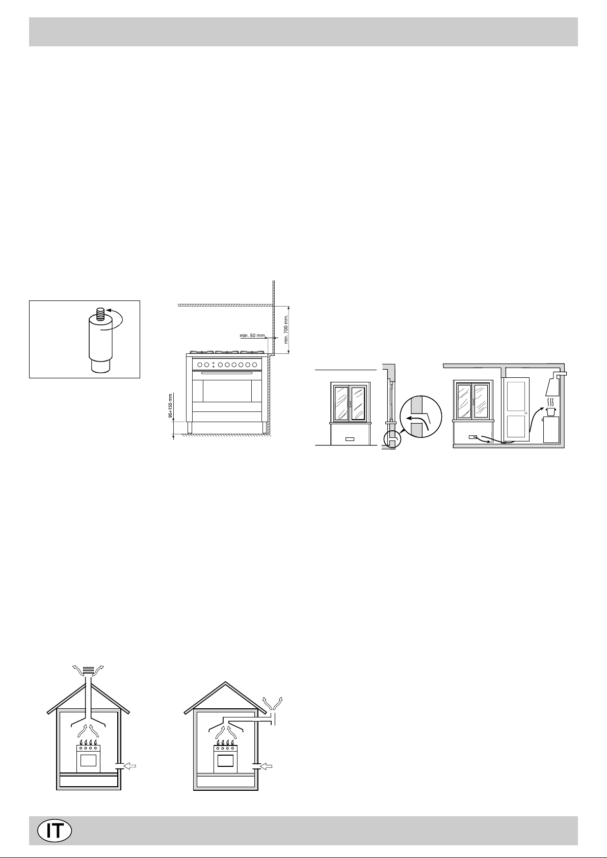
Le dimensioni di massima della cucina sono indicate nella
figura a pagina 2. Per un buon funzionamento
dell’apparecchiatura installata nei mobili, devono essere
rispettate le distanze minime indicate in fig.5. Inoltre, le
superfici adiacenti e la parete posteriore devono essere
idonee per resistere ad una sovratemperatura di 65 °C
fig.6
Ventilazione ambiente cucina
É necessario che nell’ambiente dove viene installato
l’apparecchio possa affluire una quantità di aria pari a quanta
ne viene richiesta dalla regolare combustione del gas e dalla
ventilazione dell’ambiente. L’af flusso naturale dell’aria deve
avvenire attraverso aperture permanenti praticate su pareti
del locale che danno verso l’esterno, oppure da condotti di
ventilazione singoli o collettivi ramificati conformi alla norma
UNI-CIG 7129. L’aria deve essere prelevata direttamente
dall’esterno, lontana da fonti di inquinamento. L’apertura di
aerazione dovrà avere le seguenti caratteristiche (fig.8A):
• avere una sezione libera totale netta di passaggio di almeno
6 cm² per ogni kW di portata termica nominale
dell’apparecchio, con un minimo di 100 cm² (la portata
termica è rilevabile nella targhetta segnaletica);
• essere realizzata in modo che le bocche di apertura, sia
all’interno che all’esterno della parete, non possano venire
ostruite;
• essere protette ad esempio con griglie, reti metalliche, ecc.
in modo da non ridurre la sezione utile suindicata;
• essere situate ad una altezza prossima al livello del
pavimento.
Particolare A Locale Locale da
adiacente ventilare
fig.5
Prima di installare la cucina è necessario fissare i piedini di
supporto alti 95÷155 mm in dotazione nei fori predisposti
nella parte inferiore della cucina (fig.6). Tali piedini sono
regolabili a vite, quindi permettono di eseguire il livellamento
della cucina quando è necessario.
Posizionamento
Questa apparecchiatura può essere installata e funzionare
solo in locali permanentemente ventilati secondo le
prescrizioni delle Norme UNI-CIG 7129 e 7131 in vigore.
Devono essere osservati i seguenti requisiti:
• L ’apparecchio deve scaricare i prodotti della combustione
in una apposita cappa, che deve essere collegata ad un
camino, canna fumaria o direttamente all’esterno (fig.7).
• Se non è possibile l’applicazione di una cappa, è permesso
l’uso di un elettroventilatore, installato su finestra o su
parete affacciate all’esterno, da mettere in funzione
contemporaneamente all’apparecchio.
fig.7
In camino o in canna fumaria ramificata Direttamente all’esterno
(riservata agli apparecchi di cottura)
A
Esempi di aperture di ventilazione Maggiorazione della fessura fra
per l’aria comburente porta e pavimento
Fig. 8A Fig.8B
L’afflusso dell’aria può essere ottenuto anche da un locale
adiacente purché questo locale non sia una camera da letto
o un ambiente con pericolo di incendio quali rimesse, garage,
magazzini di materiale combustibile, ecc., e che sia ventilato
in conformità alla norma UNI-CIG 7129. Il flusso dell’aria dal
locale adiacente a quello da ventilare deve avvenire
liberamente attraverso aperture permanenti, di sezione non
minore di quella suindicata. Tali aperture potranno anche
essere ricavate maggiorando la fessura tra porta e pavimento
(fig.8B). Se per l’evacuazione dei prodotti della combustione
viene usato un elettroventilatore, l’apertura di ventilazione
dovrà essere aumentata in funzione della massima portata
d’aria dello stesso. L’elettroventilatore dovrà avere una
portata sufficiente a garantire un ricambio orario di aria pari
a 3÷5 volte il volume del locale. Un utilizzo intensivo e
prolungato dell’apparecchio può necessitare di un’aerazione
supplementare, per esempio l’apertura di una finestra o
un’aerazione più efficace aumentando la potenza di
aspirazione dell’elettroventilatore se esso esiste. I gas di
petrolio liquefatti, più pesanti dell’aria, ristagnano verso il
basso. Quindi i locali contenenti bombole di GPL devono
avere delle aperture verso l’esterno al livello del pavimento,
così da permettere l’evacuazione dal basso delle eventuali
fughe di gas. Inoltre non depositare bombole di GPL (anche
vuote) in locali a livello più basso del suolo; è opportuno
9
Page 11
ISTRUZIONI PER L'INSTALLAZIONE
tenere nel locale solo la bombola in utilizzo, collegata lontana
da sorgenti di calore che possano portarla ad una
temperatura superiore a 50 °C.
Collegamento alimentazione gas
• Il collegamento dell’apparecchio alla tubazione o alla
bombola del gas deve essere effettuato secondo le
prescrizioni delle norme in vigore (UNI-CIG 7129 e 7131)
solo dopo essersi accertati che l’apparecchiatura è regolata
per il tipo di gas con cui sarà alimentata.
• Questo apparecchio è predisposto per funzionare con il
gas indicato nell’etichetta posta sul piano stesso. Nel caso
che il gas distribuito non corrisponda a quello per cui
l’apparecchio è predisposto, procedere alla sostituzione
degli iniettori corrispondenti (in dotazione), consultando il
paragrafo “Adattamento ai diversi tipi di gas”.
• Per un sicuro funzionamento, per un adeguato uso
dell’energia e maggiore durata dell’apparecchiatura,
assicurarsi che la pressione di alimentazione rispetti i valori
indicati nella tabella 1 “Caratteristiche dei bruciatori ed
ugelli”, altrimenti installare sulla tubazione di ingresso un
apposito regolatore di pressione secondo la norma UNICIG 7430.
• Effettuare Il collegamento in modo da non provocare
sollecitazioni di nessun genere sull’apparecchio.
Collegare al raccordo orientabile (filettato ½"G maschio),
posto nel lato posteriore destro dell’apparecchio (fig.9), per
mezzo di tubo metallico rigido e a raccordi conformi alla
norma UNI-CIG 7129, oppure con tubo flessibile metallico a
parete continua conforme alla norma UNI-CIG 9891, la cui
massima estensione non deve superare i 2000 mm.
Nel caso sia necessario ruotare il raccordo, sostituire
tassativamente la guarnizione di tenuta (in dotazione con
l’apparecchio). Ad installazione ultimata accertarsi che la
tenuta del circuito gas, delle connessioni interne e dei rubinetti
sia perfetta impiegando una soluzione saponosa (mai una
fiamma). Verificare inoltre che il tubo di collegamento non
possa venire a contatto con parti mobili in grado di
danneggiarlo o schiacciarlo.
Accertarsi che la conduttura del gas naturale sia sufficiente
per alimentare l’apparecchio quando tutti i bruciatori sono in
funzione.
Importante: Per effettuare l’allacciamento con gas liquido
(in bombola), interporre un regolatore di pressione conforme
alla norma UNI-CIG 7432-75.
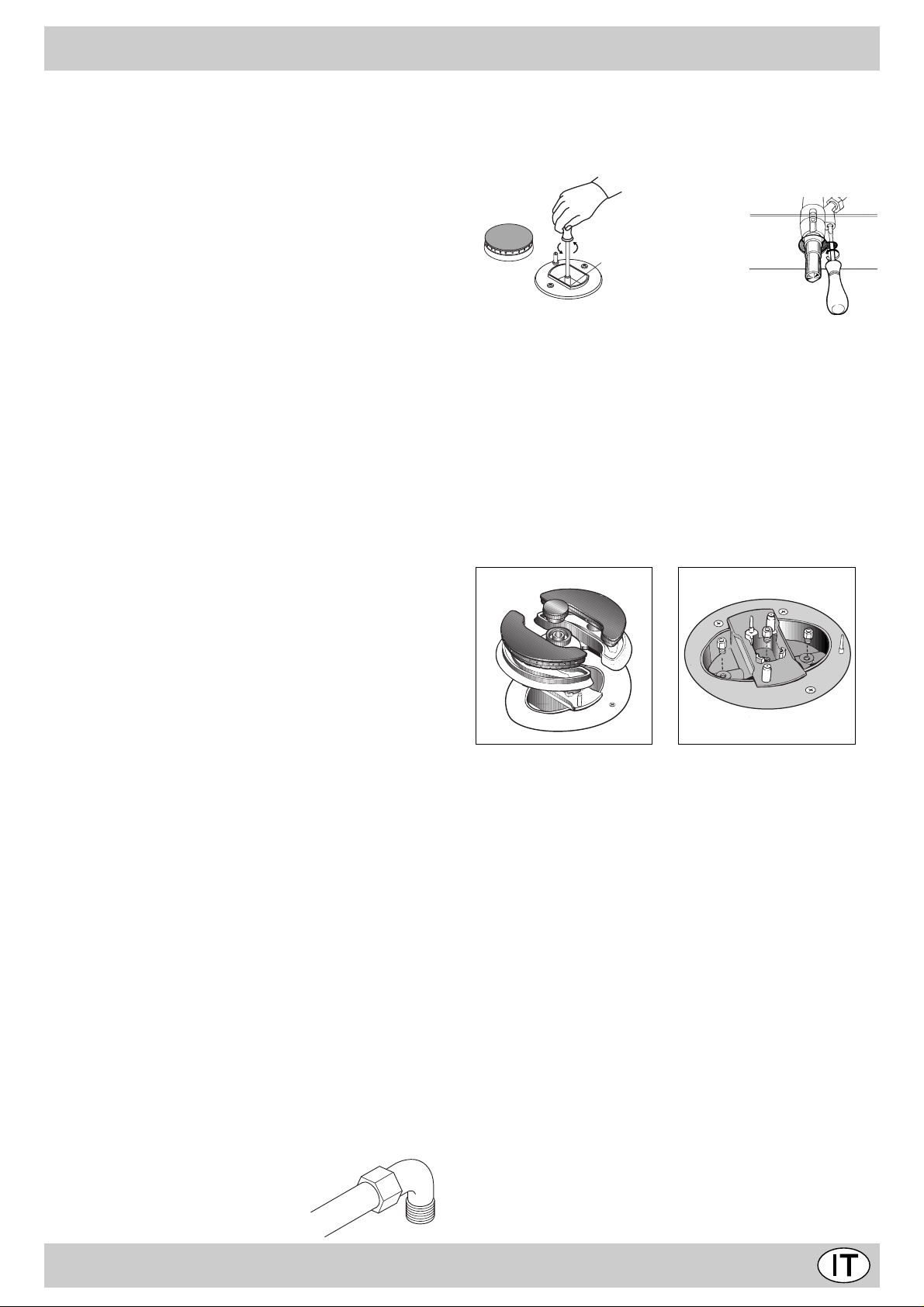
Adattamento ai diversi tipi di gas
Per adattare il piano ad un tipo di gas diverso da quello per
il quale esso è predisposto (indicato sulla etichetta fissata
nella parte superiore del piano o sull'imballo), occorre sostituire gli ugelli dei bruciatori effettuando le seguenti operazioni:
• togliere le griglie del piano e sfilare i bruciatori dalle loro
sedi.
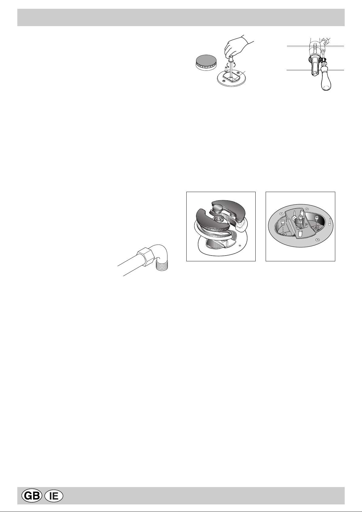
• svitare gli ugelli (fig.10), servendosi di una chiave a tubo
da 7 mm. e sostituirli con quelli adatti al nuovo tipo di gas
(vedi tabella 1 “Caratteristiche dei bruciatori ed ugelli”).
rimontare le parti eseguendo all’inverso le operazioni.
• al termine dell’operazione, sostituite la vecchia etichetta
taratura con quella corrispondente al nuovo gas d’utilizzo,
reperibile presso i Nostri Centri Assistenza Tecnica.
A
fig.10
Sostituzione degli ugelli su bruciatore a “doppie
fiamme” indipendenti:
• togliere le griglie e sfilare i bruciatori dalle loro sedi. Il
bruciatore è composto da due parti separate
(vedi Fig. C e Fig. D);
• svitare gli ugelli, servendosi di una chiave a tubo da 7 mm.
Il bruciatore interno ha un ugello, il bruciatore esterno ne
ha due (della stessa dimensione). Sostituire gli ugelli con
quelli adattati al nuovo tipo di gas (vedi tabella 1).
• rimettere in posizione tutti i componenti seguendo le ope-
razioni inverse rispetto alla sequenza di cui sopra.
Fig. C Fig. D
Regolazione aria primaria dei bruciatori
I bruciatori non necessitano di nessuna regolazione dell’aria
primaria.
Regolazione minimi
• Portare il rubinetto sulla posizione di minimo;
• togliere la manopola ed agire sulla vite di regolazione posta sulla destra del rubinetto (fig.11) fino ad ottenere una
piccola fiamma regolare, utilizzando un cacciavite (svitando la vite il minimo aumenta, avvitandola diminuisce).
N.B.: nel caso dei gas liquidi, la vite di regolazione dovrà
essere avvitata a fondo.
• Verificare che ruotando rapidamente la manopola dalla
posizione di massimo a quella di minimo non si abbiano
spegnimenti dei bruciatori.
• Negli apparecchi provvisti del dispositivo di sicurezza
(termocoppia), in caso di mancato funzionamento del dispositivo con bruciatori al minimo aumentare la portata
dei minimi stessi agendo sulla vite di regolazione.
Effettuata la regolazione, ripristinate i sigilli posti sui by-pass
con ceralacca o materiali equivalenti.
fig.11
fig.9
10
Page 12
COLLEGAMENTO ELETTRICO
È OBBLIGATORIO IL COLLEGAMENTO A TERRA
DELL’APPARECCHIATURA.
L'apparecchiatura è predisposta per il funzionamento con
corrente alternata alla tensione e frequenza di alimentazione
indicate sulla targhetta caratteristiche (posta sul retro o alla
fine del libretto istruzioni). Accertarsi che il valore locale della
tensione di alimentazione sia lo stesso di quello indicato
sulla targhetta.
Allacciamento del cavo alimentazione elettrico alla rete
Per i modelli privi di spina, montare sul cavo una spina
normalizzata per il carico indicato sulla targhetta
caratteristiche e collegarla ad una adeguata presa di
corrente. Desiderando un collegamento diretto alla rete è
necessario interporre tra l’apparecchio e la rete un
interruttore onnipolare con apertura minima tra i contatti di 3
mm., dimensionato al carico e rispondente alle norme in
vigore. Il filo di terra giallo-verde non deve essere interrotto
dall’interruttore. Il cavo di alimentazione deve essere
posizionato in modo che non raggiunga in nessun punto
una temperatura superiore di 50 °C a quella ambiente. Tutti
gli apparecchi devono essere collegati separatamente. Non
CARATTERISTICHE DEI BRUCIATORI ED UGELLI
utilizzare riduzioni, adattatori o derivatori in quanto essi
potrebbero provocare riscaldamenti o bruciature. Prima di
effettuare l’allacciamento accertarsi che:
• la valvola limitatrice e l’impianto domestico possano
sopportare il carico dell’apparecchiatura (vedi targhetta
caratteristiche);
• l’impianto di alimentazione sia munito di efficace
collegamento a terra secondo le norme e le disposizioni di
legge in vigore;
• la presa o l’interruttore onnipolare siano facilmente
raggiungibili con il piano installato.
DECLINIAMO OGNI RESPONSABILITÀ NEL CASO LE
NORME ANTINFORTUNISTICHE NON VENGANO
RISPETTATE.
Sostituzione del cavo
Utilizzare un cavo in gomma del tipo H05VV-F con una
sezione 3 x 1.5 mm².
Il conduttore giallo-verde dovrà essere più lungo di 2÷3 cm.
degli altri conduttori.
1allebaT odiuqilsaGelarutansaG
EROTAICURB
.CodipaR
.BodiparimeS
.AoirailisuA
.D )onretniRDCD(emmaifeippoD
.D )onretsERDCD(emmaifeippoD
enoizatnemilaidinoisserP
* A 15°C e 1013 mbar-gas secco
Propano G31 H.s. = 50,37 MJ/kg
Butano G30 H.s. = 49,47 MJ/kg
Naturale G20 H.s. = 37,78 MJ/m
ortemaiD
)mm(
00100.37.00468812412611682
5756.14.0034602181169751
550.13.0720537171759
0309.04.0034456460768
03101.43.17507892392011093
aznetoP
acimret
)*.s.H(Wk
.nimoN.todiR03G13G02G
ssap-yB
001/1
)mm(
)rabm(elanimoN
)rabm(aminiM
)rabm(amissaM
ollegU
001/1
)mm(
h/g
03-82
02
53
*atatroP
73
52
54
ollegU
001/1
)mm(
*atatroP
h/l
02
71
52
Questa apparecchiatura è conforme alle seguenti
Direttive Comunitarie:
- 73/23/CEE del 19/02/73 (Bassa Tensione) e successive
3
modificazioni;
- 89/336/CEE del 03/05/89 (Compatibilità Elettromagnetica) e successive modificazioni;
- 90/396/CEE del 29/06/90 (Gas) e successive
modificazioni;
- 93/68/CEE del 22/07/93 e successive modificazioni.
11
Page 13

SAFETY PRECAUTIONS
Congratulations on choosing an Ariston appliance, which you will find is dependable and easy to use. W e recommend that
you read this manual for best performance and to extend the life of your appliance. Thank you.
THESE INSTRUCTIONS ARE ONL Y V ALID FOR THE COUNTRIES OF DESTINA TION WHOSE SYMBOLS ARE SHOWN
IN THE BOOKLET AND THE APPLIANCE RATING PLATE.
1. This appliance has been designed for private, non-
professional use in normal dwellings.
2. Read the recommendations in this instruction
booklet carefully, as they give important advice
regarding safe installation, use and maintenance.
Keep this booklet in a safe place for further
reference when required.
3. Oven accessories which may come into contact with
food are made of materials which comply with the
contents of EEC Regulation 89/109 of 21.12.88 and
national regulations in force.
4. After having removed the packaging, check that the
appliance is intact. If in doubt, do not use the appliance
and contact professionally qualified personnel.
5. Some parts are covered with a removable scratch-proof
film. Before using the appliance the film should be
removed and the underlying part cleaned with a cloth
and a non-abrasive household cleaning product. When
switching on for the first time, it is advisable to heat the
empty oven at maximum temperature for about 30
minutes to eliminate any residue from manufacture.
6. All installation and adjustment operations should be
carried out by qualified technicians in accordance with
current regulations. Specific indications are given in
the “instructions for the installer” paragraph.
8. During operation, the oven glass door and adjacent
parts of the appliance become hot. Make sure,
therefore, that children do not touch the appliance.
For greater safety, an additional child-safety device is
available from our Head Office and our Authorised
Service Centres (see enclosed list). When ordering this,
please give the code: BAB - followed by the appliance
model. The model is stamped on the plate which is
visible on the front part of the oven upon opening the
door.
9. Check that the capacity of the electrical system and
the power outlets are suitable for the maximum power
of the appliance, indicated on the rating plate. If in doubt,
consult a professionally qualified technician.
10. Periodically check the condition of the gas connection
pipe and have it replaced by a qualified technician as
soon as it shows any signs of wear or anomaly.
11. Under no circumstances should the user replace the
power supply cable or the gas connection pipe of this
appliance. In the event of damage or the necessity for
replacement, only contact an authorised service centre.
12. Do not leave the appliance plugged in if it is not in use.
Switch off the main switch and gas supply when you
are not using the cooker.
13. The burners and the cast-iron pan supports remain hot
for a long time after use. Take care not to touch them.
7. Before connecting the appliance, make sure that the
data on the rating plate (situated on the rear part of the
appliance and on the last page of the instruction
booklet) correspond to those of the mains electricity
and gas supplies.
14. To avoid accidental spillage do not use cookware with
uneven or deformed bottoms on the burners.
15. Never use flammable liquids such as alcohol or
gasoline, etc. near the appliance when it is in use.
16 .If the cooker is placed on a pedestal, take the necessary
precautions to prevent the same from sliding off the
pedestal itself.
1
Page 14
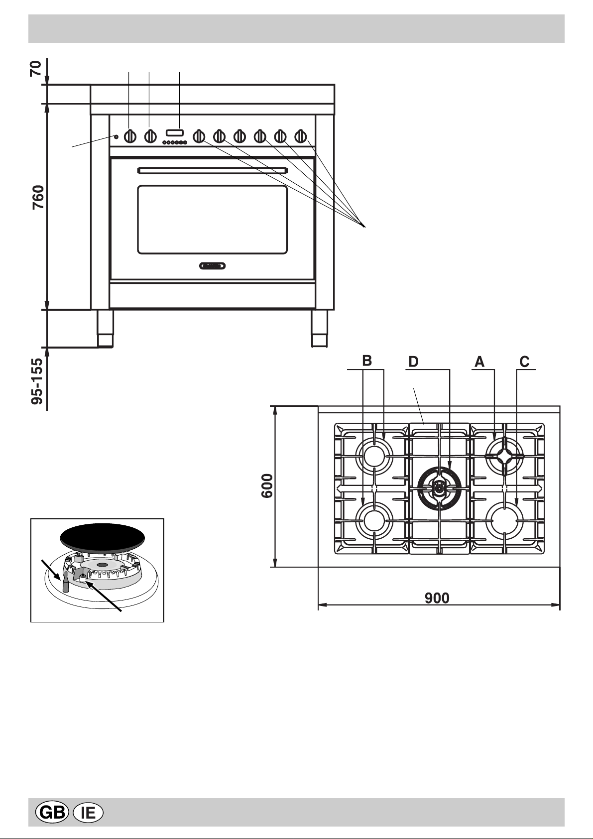
COOKER DESCRIPTION
S
GH
T
M
R
F
E
A Auxiliary gas burner
B Semi-rapid gas burner
C Rapid gas burner
D Triple ring gas burner
R Support Grid for Cookware
M Control Knobs for Gas Burners
E Ignitor for Gas Burners
F Safety Device - Activates if the flame accidentally goes
out (spills, drafts, etc.), interrupting the delivery of gas
to the burner.
T Minute minder
S Electric oven operation indicator light
G Electric oven selector knob (cooking function
selection)
H Electric oven thermostat knob (temperature
selection)
2
Page 15
INSTRUCTIONS FOR USE
HOB OPERA TION
The burners are fitted with automatic ignition and a
thermocouple safety device, which automatically cuts off
the gas from the burner in a few seconds if the flame
accidentally goes out during operation.
The burners differ in size and power. Choose the most
appropriate one for the diameter of the cookware being
used.
Each burner can be regulated with the corresonding control
knob "M" by using one of the following settings:
Off
High flame
Low flame
The symbols near the knobs show the position of the
relative burner on the hob.
To ignite a burner, proceed as follows:
• turn the relative knob counter-clockwise until the pointer
is on the high-flame symbol;
• press the knob down fully and activate the automatic gas
ignition marked with the symbol ;
• keep the knob pressed down for about 10 seconds with
the flame lit to allow the safety thermocouple to be heated;
• release the knob, checking that the flame is stable. If it is
not, repeat the operation.
For minimum power, turn the knob towards the low flame
symbol. Intermediate positions are possible by simply
putting the knob anywhere between the high and the low
flame symbol.
To turn off the burner, turn the knob clockwise to the off
position " " .
Important:
• Do not activate the automatic ignition device for more
than 15 consecutive seconds.
• Difficulty in ignition is sometimes due to air inside the
gas duct.
• If a burner flame accidentally goes out, the gas continues
to exit for a few moments before the safety device
activates. Turn the control knob to the off position and do
not attempt ignition again for at least 1 minute, thereby
letting the gas disperse, which could otherwise be a
danger.
• When the appliance is not in operation, check that the
knobs are in the off position " ". The main gas supply
cut-off cock should also be closed.
Using the burners
To obtain maximum efficiency from the burners, it is
advisable to only use pans with a diameter suitable for the
burner being used, so that the flame does not extend beyond
the pan base (see following table). When a liquid starts
boiling, it is advisable to turn the flame down just enough to
keep the liquid simmering.
renruB)mc(retemaiderawkooCø
.AyrailixuA
.BdipaR-imeS
.CdipaR
.D)lanretniRDCD(emalFelbuoD
.D)lanretxeRDCD(emalFelbuoD
41–6
02–51
62–12
41-01
82-42
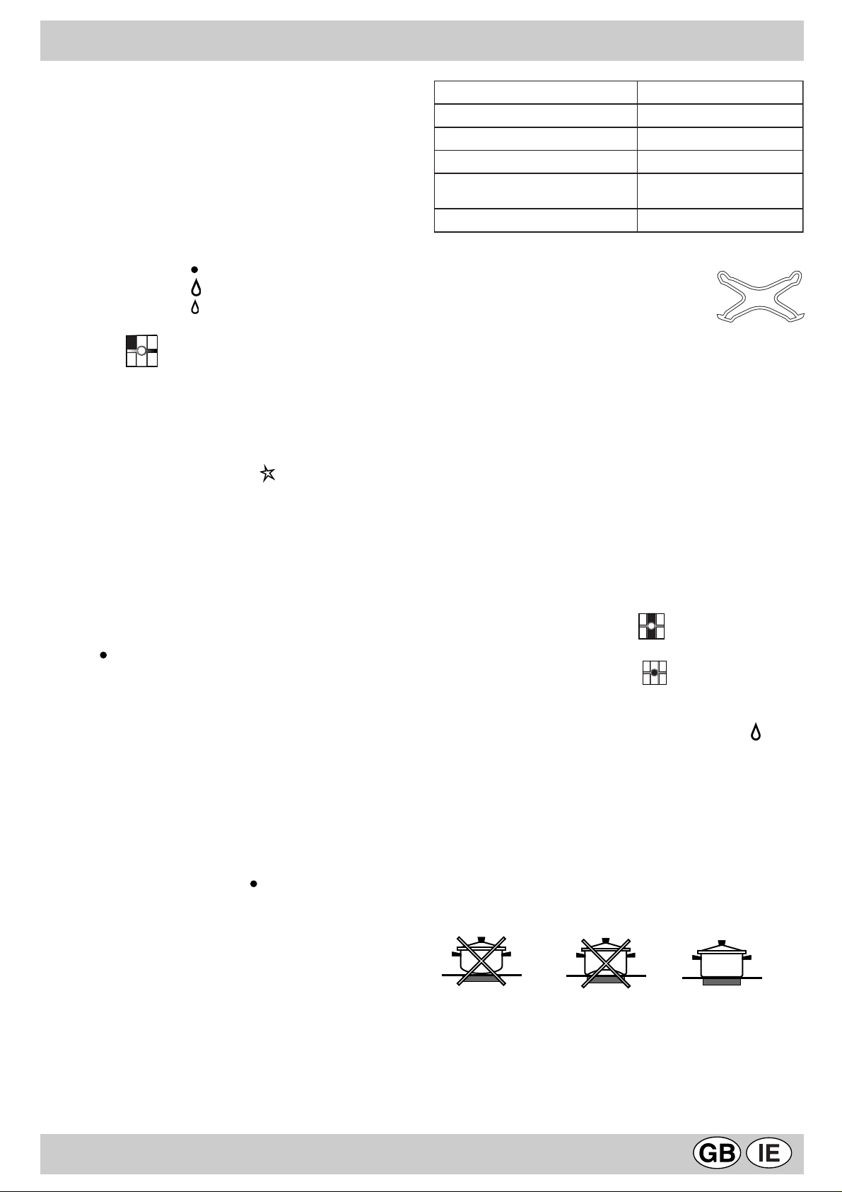
The hob is fitted with two pan reducing
supports (fig.1), which should only be used
on the auxiliary burner "A" and on the
Double Flame "D" (DC-DR internal).
fig.1
The “separate double flame” burner
This burner consists of two concentric burners which can
operate either together or separately.
Use of the double flame on the maximum setting gives a
very high power which reduces cooking times with respect
to conventional burners.
Moreover the double flame crown provides a more uniform
distribution of heat on the bottom of the pan, when using
both burners on minimum.
Pots and pans of all sizes can be used. In the case of the
smaller pots and pans we recommend the use of only the
internal burner.
There is a separate control knob for each of the “separate
double flame” burners.
The knob marked by the symbol operates the external
burner;
The knob marked by the symbol operates the internal
burner.
To turn on one of the rings, press the relative knob in all the
way and turn it anti-clockwise to the high setting . The
burner is fitted with an electronic igniter that automatically
starts when the knob is pressed in.
Since the burner is equipped with a safety device "F",
after lighting the burner keep the knob pressed in for about
6 seconds to allow the device which keeps the flame lit
automatically to heat up.
To obtain the best results with the cooktop, several
fundamental rules should be followed while cooking or
preparing food. Use cookware with a flat bottom to make
certain that the pot sets properly on the cooking area.
3
Page 16
THE "MAXIOVEN"
MUL TI-FUNCTION OVEN
The oven offers nine combinations of heating elements; so
the most suitable combination may therefore be chosen for
each dish, with convincing results.
By turning the selector knob “G” marked with the symbol
, different cooking modes are obtained, as shown in
the following table:
lobmyS noitcnuF rewoP
0
ffO)0-
gnitaehmottoB+poT)1
stnemele
W0532
tnemelegnitaehmottoB)2W0031
tnemelegnitaehpoT)3W0501
tnemelegnitaehllirG)4W0002
gnitaehllirG+poT(llirgixaM)5
)stnemele
gnitaehllirG+poT(llirgixaM)6
naf+)stnemele
W0503
W0013
naF+tnemelegnitaehmottoB)7W0531
+tnemelegnitaehdnuorraeR)8
naF
W0582
is particularly indicated for meats which should remain
tender on the inside.
T o grill, turn the selector knob "H" to one of these positions:
(grill),
During grilling, do not set the thermostat knob to
above 200°C and keep the oven door closed.
Oven light
The oven light comes on automatically when the selector
knob is turned to any of its positions.
Indicator light "S"
It indicates that the oven is heating up. When the light goes
out, the required temperature has been reached inside the
oven.
When the light alternately comes on and goes out, it means
that the thermostat is working properly to maintain the oven
temperature.
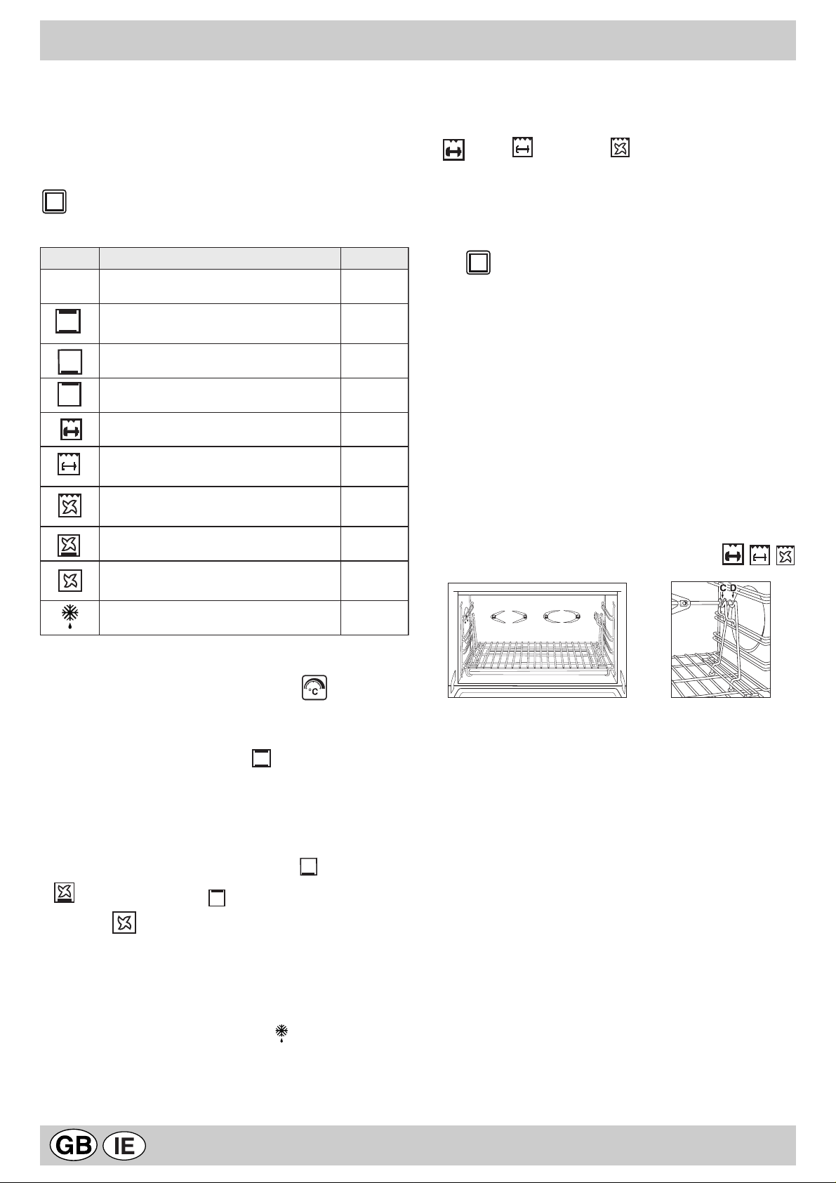
Spit - Rotisserie
Insert the meat to be cooked along the length of the spit
rod, securing it with the special adjustable forks (fig. 2a).
Introduce the supports “A” and “B” (fig. 2b) into the holes in
the drip tray “E”, rest the rod groove on the seat “C” and
insert the oven rack into the lowest guide of the oven; now
insert the spit rod into the relative hole, moving the groove
forward into seat “D”. Start the rotisserie by turning the
selector knob to one of the following positions:
(maxigrill),
(maxigrill + fan)
gnitsorfedtsaF)9W05
After having selected the heat source, put the thermostat
knob "H" (marked with the symbol ) onto the
temperature required.
• For traditional cooking (roasts, biscuits, etc.) in
conventional mode use the
below).
Only put the food to be cooked into the oven when it has
reached the selected temperature and preferably use just
one shelf for cooking.
To provide heat only to the bottom or the top part of the
dishes, turn the selector to the position (hot below) or
(hot below + fan) or
• With this (fan assisted) mode heat is transmitted to
the food through pre-heated air made to circulate inside
the oven by a fan. The oven heats up very quickly so the
food to be cooked may be put into the oven as soon as it
is switched on. Cooking is also possible simultaneously
on two shelves.
• The “fast defrosting“ function uses no heating
elements, just the oven light and the fan.
• Grill operation: a high heat output is used for grilling, so
that the surface of the food is immediately browned; this
(hot above);
mode (hot above +
AB
Fig. 2a
Fig. 2b
4
Page 17
HOW TO KEEP YOUR OVEN IN SHAPE
Before cleaning your oven, or performing maintenance,
disconnect it from the power supply.
T o extend the life of your oven, it must be cleaned frequently ,
keeping in mind that:
• The self-cleaning panels (if present) and the enameled
parts should be washed with warm water - abrasive
powders and corrosive substances should be avoided;
• The inside of the oven should be cleaned immediately
after use with warm water and soap; the soap should be
rinsed away and the interior dried thoroughly;
• Stainless steel can be stained if it remains in contact
with agressive detergents (containing phosphorus) or
water with a high lime content. We recommend that you
rinse these parts thoroughly and dry them well after
cleaning. It is also a good idea to dry any water spills;
• Never line the bottom of the oven with aluminium foil
because the buildup of heat will not only impede the
cooking process, but could also damage the enamel.
Replacing the Lamp in the Oven
• Cutoff the supply of power to the oven by turning off the
omni-polar switch connecting it to the mains, or by
removing the plug if it is accessible;
• Unscrew the glass cover attached to the lamp holder;
• Unscrew the lamp and replace it with another high-temperature lamp (300°C) with the following characteristics:
- Voltage: 230/240 V
- Wattage: 15W
- Socket: E14
• Remount the glass cover and reconnect the appliance
to the power supply.
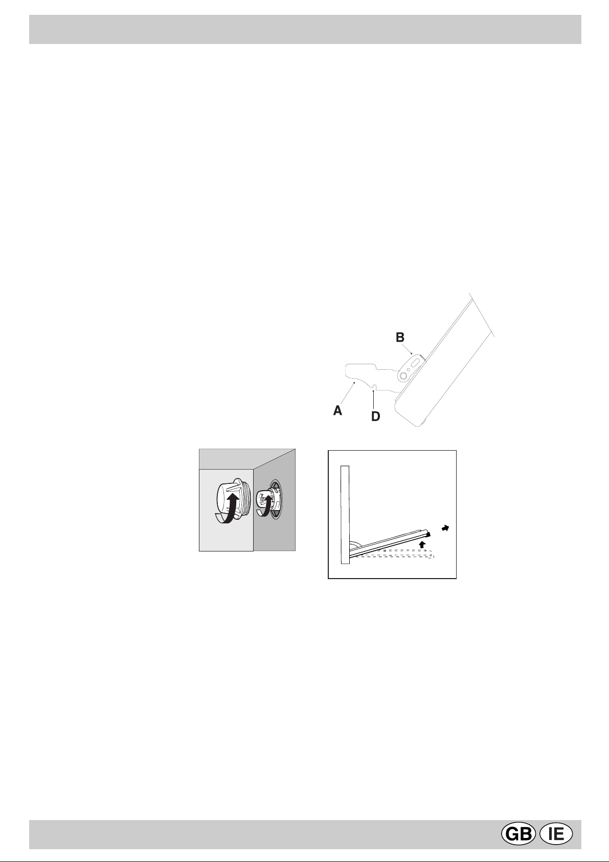
Disassembling/assembling the oven door
To make it easier to clean the inside of your oven, the
oven door can be removed, by proceeding as follows (fig.
3-4):
• Open the door completely and lift the 2 levers “B” (fig.
3);
• Now, shutting the door slightly , you can lift it out by pulling
out the hooks “A” as shown in figure 4.
To reassemble the door:
• With the door in a vertical position, insert the two
hooks “A” into the slots;
• Ensure that seat “D” is hooked perfectly onto the edge
of the slot (move the oven door backwards and forward
slightly);
• Keep the oven door open fully, unhook the 2 levers “B”
downwards and then shut the door again.
fig 3
fig 4
5
Page 18
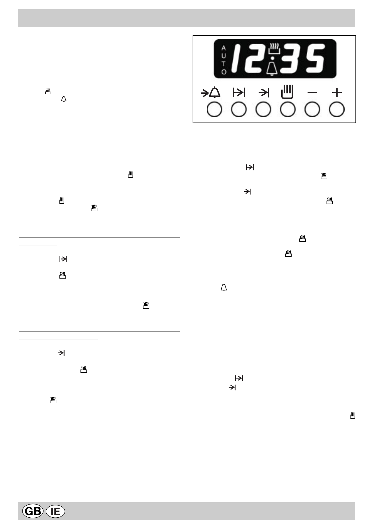
THE ELECTRONIC PROGRAMMER
The electronic programmer has the function of
automatically switching on the oven (at the required time)
and switching it off at the end of the set cooking time. The
4 figure luminous display showing the actual time and the
programming times, also shows the current state of the
oven by means of the following symbols:
Oven on
Minute minder
Automatic programme AUTO
Point • (this divides the hour from the minutes on the
display)
All the functions may be programmed for a total of 23 h
and 59 min. Maximum cooking time is 10 hours.
Adjusting the clock
(At installation, after power failures, clock in advance or
behind).
Select manual mode by pressing key , adjust the hour
and minutes using the -and + keys.
Manual oven mode (Programming excluded)
Press the key ; and the oven is switched on, the AUTO
symbol goes out and the (oven on) symbol comes on.
This operation erases any set programme.
Semi-automatic oven mode
1st example: start in manual cooking mode - programmed
cooking time.
• Put the food to be cooked in the oven.
• Press the key (duration) and adjust the cooking
time using the -and + keys: the oven switches on, the
AUTO and (oven on) symbols light up.
• Turn the selector and the thermostat knobs onto the
required function and temperature respectively.
• At the end of the set cooking time, the oven is
automatically switched off, the symbol (oven on)
goes out and the AUTO symbol blinks; an acoustic signal
sounds.
2nd example: start with manual cooking mode - end with
programmed cooking mode.
• Put the food to be cooked in the oven.
• Press the key (end of cooking) and adjust the end
of cooking time using the - and + keys: the oven switches
on, the AUTO and symbols light up.
• Turn the selector and the thermostat knobs onto the
required function and temperature respectively.
• At the end of cooking, the oven is automatically switched
off, the symbol (oven on) goes out and the AUTO
symbol blinks; an acoustic signal sounds.
Automatic oven mode (programmed cooking duration and
end)
• Put the food to be cooked in the oven.
• Press the key (Duration) and adjust the cooking
time using the - and + keys: the AUTO and (oven on)
symbols light up (the oven switches on).
• Press the key (end of cooking) and adjust the end
of cooking time using the - and + keys: the symbol
goes out (the oven switches off).
• Turn the selector and the thermostat knobs onto the
required function and temperature respectively.
• The programmer automatically sets the start of cooking
time, which is shown by the symbol (oven on) coming
on. When the cooking time has elapsed, the oven is
automatically switched off, the (oven on) symbol goes
out and the AUTO symbol blinks; an acoustic signal
sounds.
Minute minder
Press the key (minute minder) and set the time required
using the - and + keys. An acoustic signal sounds at the
end of the programme.
Buzzer
The buzzer emits a sound for 7 minutes after the end of
the selected programme; it may be stopped by pressing
any function key. It is possible to choose 3 different types
of acoustic signal. By pressing the - key the actual signal
tone appears. Now, within 7 seconds, every further press
of the - key changes the signal tone.
Program control
Press the key for the remaining time to be displayed,
and the key to check the end of cooking time.
Erasing programs
Once a programme has been carried out, it is automatically
erased; it can also be cancelled by pressing the key
(manual).
6
Page 19
PRACTICAL COOKING ADVICE
Preheating
If the oven must be preheated (generally this is the case
Cooked well on the insi de but stic ky on the outside
when cooking leavened foods) the “ventilation” mode
can be used to reach the desired temperaure as quickly
as possible in order to save on energy.
Once the food has been placed in the oven, the most
appropriate cooking mode can then be selected.
Using the Grill
Use the “grill” it allows you to grill small portions like
toasted sandwiches, hotdogs, etc., to perfection.
Position the food under the center of the grill because only
the central part of the top heating element is turned on.
Food placed in the corners will not cook properly.
The “Ventilated Grill” is extremely useful for grilling
foods rapidly, as the distribution of heat makes it possible
not only to brown the surface, but also to cook the bottom
part.
This mode can also be used for browning foods at the end
of the cooking process.
Important: always use the grill with the oven door
closed. This will allow you both to attain excellent results
and to save energy (10% circa).
For the best results when cooking on the grill, it is
recommended to use the highest setting of the thermostat
(200°C), which utilizes infrared rays. The grill should be
placed on the higher racks (see the cooking chart). To
catch fat and prevent smoke, place a dripping pan beneath
the rack used for grilling.
Use less liquid, lower the temperature, and incr ease t he
cooking time.
The pastry sticks to the pan
Grease the pan well and sprinkl e it with a dusti ng of
flour.
I used more than one level and they are not all at the
same cooking point
Use a lower temperature setting. It is not necessar y to
remove the food from all the racks at the same ti me.
Cooking Pizza
For best results when cooking pizza use the "ventilation
mode" :
• Preheat the oven for at least 10 minutes;
• Use a light aluminum pizza pan, placing it on the broiler
supplied with the oven. If the dripping-pan is used, this
will extend the cooking time, making it difficult to get a
crispy crust;
• Do not open the oven door frequently while the pizza is
cooking;
• If the pizza has a lot of toppings (three of four), it is
recommended that the mozzarella cheese be placed
on top halfway through the cooking process;
When utilizing the grill, place the rack at the lower levels
(see cooking table). To catch grease or fat and prevent
smoke, place a dripping-pan at the bottom rack level.
Baking Pastries
When baking pastries, always place them in the oven after
it has been preheated. Make sure you wait until the oven
has been preheated thoroughly (the red "S" light will turn
off). Do not open the door while the pastry is cooking in
order to prevent it from dropping.
Batters must not be too runny , as this will result in prolonged
cooking times. In general:
Pastry is too dry
Increase the temperature by 10°C and reduce the
cooking time.
Pastr y dropped
Use less liquid or lower the the temperature by 10°C.
Pastry is too dar k on top
Place it on a lower rack, lower the temperature, and
increase the cooking ti me.
Cooking Fish and Meat
Meat must weigh at least 1 Kg in order to prevent it from
drying out. When cooking white meat, fowl and fish, use
low temperature settings (150°C-200°C). For red meat that
should be well done on the outside while tender and juicy
in the inside, it is a good idea to start with a high temperature setting (200°C-220°C) for a short time, then turn the
oven down afterwards. In general, the larger the roast, the
lower the temperature setting. Place the meat on the centre
of the rack and place the dripping pan beneath it to catch
the fat.
Make sure that the rack is inserted so that it is in the
centre of the oven. If you would like to increase the amount
of heat from below, use the low rack heights. For savory
roasts (especially duck and wild game), dress the meat
with lard or bacon on the top.
7
Page 20
COOKING TIPS
Cooking times may change according to the nature of the foods, their homogeneity and their volume. When cooking a certain food for the first
time, it is advisable to choose the lowest values in the cooking time range given in the table and then increase them if necessary .
CONVENTIONAL OVEN COOKING
hsidfoepyT
erutarepmeT
C°
sekacdnaseirtsaP
eiptiurF
seugnireM
ekacegnopS
ekaclegnA
ekacariedaM
ekacetalocohC
faolteewstalF
sffuP
stiucsibyrtsapykalF
selliuefelliM
yrtsaptrohS
031
031
051
061
061
071
071
002
002
002
002
hsidfoepyT
).gk5.0(spohC
segasuaS
)gk1(nekcihcdellirG
).gk6.0(tipsehtnolaeV
FAN ASSISTED COOKING
hsidfoepyT
emitgnikooC
)setunim(
07-06
04-03
03-02
05-04
05-04
04-03
05-04
02-51
02-51
02-51
02-51
GRILLING
).gk1(tipsehtnonekcihC
hsidfoepyT
taeM
).gk8-4(yekruT
).gk5-4(esooG
).gk4-2(kcuD
).gk3-½2(nopaC
feebdesiarB).gk½1-1(
bmalfogeL
).gk2(erahtsaoR
tnasaehptsaoR
).gk½1-1(nekcihC
hsiF
emitgnikooC
)setunim(
06
51
06
06
06
.oNliarediuG
mottobmorf
ytitnauQ
.gk
erutarepmeT
C°
061
061
071
071
061
061
061
061
071
002
flehsfonoitisoP
liarediugdr3
liarediugdn2
liarediugts1
-
-
C°
The 1st guide rail is
understood as being
the lowest position.
erutarepmeT
emiT
emitgnikooC
)sruoh(
½4-3
½4-4
½2-½1
½2-2
½3-3
½1-1
½1-1
½1-1
½1-1
setunim52-51
)setunim(
sekacdnaseirtsaP
taeM
laeV
feeB
kroP
nekcihC
laeV
feeB
kroP
nekcihC
kcuD
hsiF
sretsyO
selabmiT
gnitsorfeD
taeM
taeM
taeM
llirgrednustsaoR
feebtsaorhsilgnE
yartnostsaoR
secilsyekruT
seloressaC
feebdesiarB
laevdesiarB
hsidatsapdekaB
gniddupelbategeV
sehciwdnasdetsaoT
sehsidtae-ot-ydaeR
dluomni,ximnetaebhtiW*
esabnalf,yrtsaptrohS
nomlas,tobrut,lerekcaM
dluomtuohtiw,ximnetaebhtiW*
gnilliftewhtiwyrtsaptrohS
gnillifyrdhtiwyrtsaptrohS
ximdenevaellarutanhtiW*
sekacdnaseirtsapllamS
elos,ekahdoc,skaets,stelliF
sélffuosyruovasdnateewS*
lloryruovasdnasazziP*
3-1
4-3-1
4-3-1
3-1
4-3-1
3-1
4-3-1
2
2
2
2
2
3-1
3-1
3-1
3-1
3-1
3-1
1
1
3-1
3.1
3-1
3-1
3-1
3-1
4-3-1
4-3-1
3-1
3-1
3-1
3-1
1
1
5.0
5.1
1
1
5.0
1
1
1
1
5.1-1
1
1
1
5.1-1
5.1
5.1-1
1
1
1
1
2
2
57.0
5.0
5.0
1
5.0
57.0
1
571
571
571
571
571
571
061
081
081
022
081
002
061
061
061
081
081
081
571
571
081
081
081
581
581
081
002
091
002
05
05
05
06
05
03
07
54
05
03
06
07
05
07
07
08
09
09
09
021
021
021
011
03
54
02
06
05
05
03
51
54
05
07
011
Notes:
1) Cooking times do not include oven pre-heating, except for those marked with an asterisk
2) The indication given in the table for the guide rails is the one that should preferably be used in the event of cooking on more than one level.
3) The indicated times refer to cooking on one shelf only; for cooking on more than one level, increase the time by 5 ÷ 10 min.
4) For roast beef, veal, pork and turkey, on the bone or rolled, increase the times by 20 min.
8
Page 21
INSTALLA TION
The following instructions are provided for qualified
installers so that they may accomplish installation,
adjustment and technical maintenance operations correctly
and in compliance with current regulations and standards.
Important: the appliance should be disconnected from
the mains electricity supply before any adjustment,
maintenance, etc. is carried out. Maximum caution should
be used should it be necessary to keep the appliance
connected to the electricity supply.
The cookers have the following technical specifications:
Category: II 2H3+ Class: 1
The dimensions of the appliance are given in the figure on
page 2. For trouble-free operation of appliances installed
in housing units, the minimum distances shown in fig.5
should be observed. Adjacent surfaces and the wall at the
rear should also be able to withstand an overheating
temperature of 65 °C.
Kitchen ventilation
The air flow into the room where the appliance is installed
must equal the quantity of air that is required for regular
combustion of the gas and for ventilating the same room.
Air must be taken in naturally through permanent apertures
made in the outside walls of the room or through single or
branching collective ventilation ducts in compliance with
current standards and regulations. The air must be taken
directly from the outside, from an area far from sources of
pollution. The ventilation aperture must have the following
characteristics (fig.8A):
• total free cross section of passage of at least 6 cm² for
every kW of rated heating capacity of the appliance,
with a minimum of 100 cm² (the heating capacity is
indicated on the rating plate);
• it must be made in such a way that the aperture, both on
the inside and outside of the wall, cannot be obstructed;
• it must be protected, e.g. with grates, wire mesh, etc. in
such a way that the above-mentioned free section is not
reduced;
• it must be situated as near to floor level as possible.
Detail A Adjacent Room to be
room ventilated
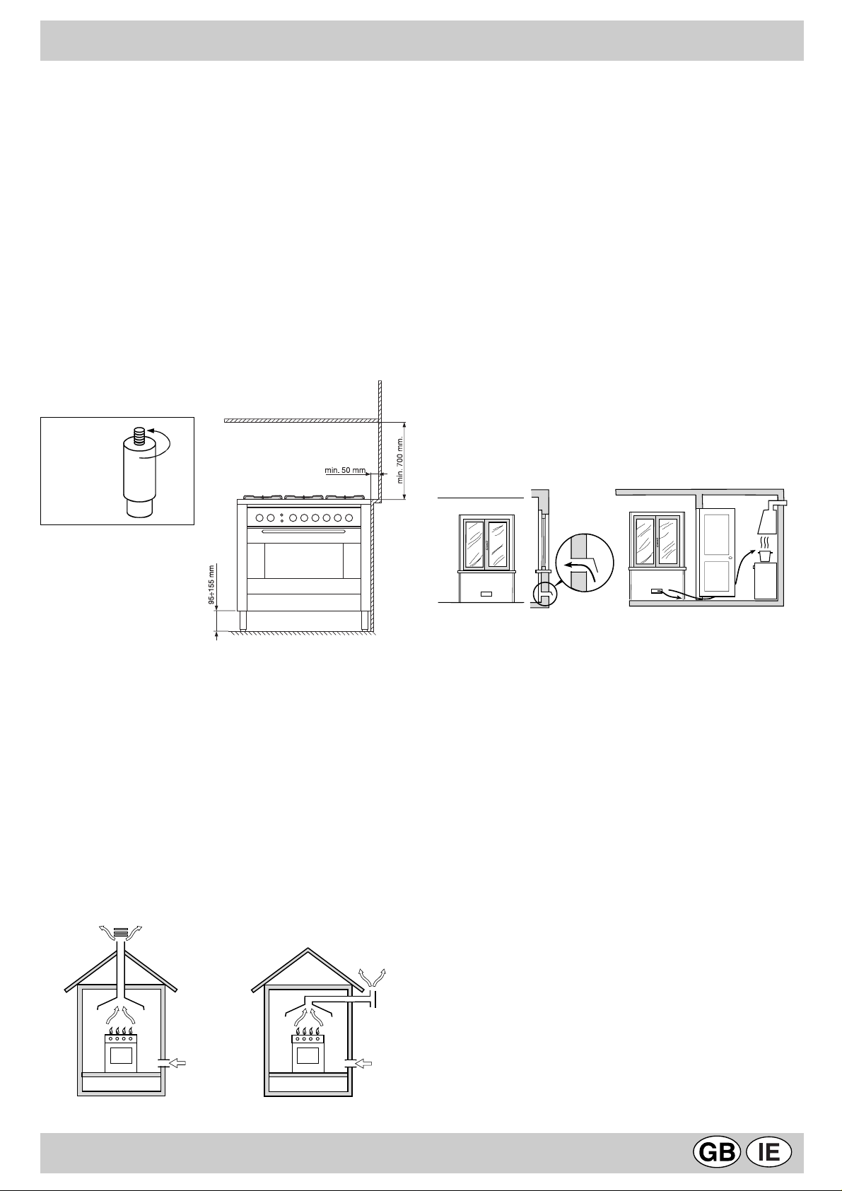
fig.6
fig.5
Prior to installing the cooker, 95 ÷ 155 mm high supporting
feet (provided) should be fitted into the holes to be found
in the bottom of the cooker (fig.6). These feet are screwadjustable and whenever necessary should be used to
make sure the cooker stands level.
Positioning
This appliance may only be installed and operated in
permanently ventilated rooms in compliance with current
standards. The following requirements must be observed:
• The appliance must discharge combustion products into
a special hood, which must be connected to a chimney,
flue pipe or directly to the outside (fig.7).
• If it is impossible to fit a hood, the use of an electric fan
is permitted, either installed on a window or on an external
wall, which must be switched on at the same time as the
appliance.
fig.7
In a chimney stack or branched flue Directly to the outside
(exclusively for cooking appliances)
A
Examples of ventilation holes Enlarging the ventilation slot
for comburant air between window and floor
fig. 8A fig. 8B
The air inflow may also be obtained from an adjoining room,
provided the latter is not a bedroom or a room where there
is a risk of fire, such as warehouses, garages, fuel stores,
etc. and is ventilated in compliance with the current
standards and regulations. Air from the adjoining room to
the one to be ventilated may be made to pass freely
through permanent apertures with a cross section at least
equal to that indicated above. These apertures may also
be obtained by increasing the gap between the door and
the floor (fig.8B). If an electric fan is used for extracting
the combustion products, the ventilation aperture must
be increased in relation to its maximum performance. The
electric fan should have a sufficient capacity to guarantee
an hourly exchange of air equal to 3 ÷ 5 times the volume
of the kitchen. Prolonged, intensive use of the appliance
may require extra ventilation, e.g. an open window or a
more efficient ventilation system by increasing the
extraction power of the electric fan if installed. Liquid
petroleum gas descends towards the floor as it is heavier
than air. Apertures in the outside walls in rooms containing
LPG cylinders should therefore be at floor level, in order
to allow any gas from leaks to be expelled. Do not store
LPG cylinders (even when empty) in basements or rooms
below ground level; it is advisable to keep only the cylinder
in use in the room at any one time and connected far from
heat sources which could raise its temperature to above
50 °C.
9
Page 22
INSTALLATION
Gas supply connection
• Check that the appliance is set for the type of gas
available and then connect it to the mains gas piping or
the gas cylinder in compliance with current regulations
and standards.
• This appliance is designed and set to work with the gas
indicated on the label situated on the actual hob. If the
gas supply is other than the type for which the appliance
has been set, proceed with replacing the corresponding
nozzles (provided), following instructions given in the
paragraph “Adaptation to different types of gas”.
• For trouble-free operation, suitable use of energy and
longer life of the appliance, make sure that the supply
pressure complies with the values indicated in the table
1 "burners and nozzles specifications, otherwise install
a special pressure regulator on the supply pipe in
compliance with current standards and regulations.
• Connect in such a way that the appliance is subjected to
no strain whatsoever.
Either a rigid metal pipe with fittings in compliance with the
standards in force must be used for connecting to the nipple
union (threaded ½"G male fitting) situated at the rear of
the appliance to the right (fig.9), or flexible steel pipe in
compliance with the standards in force, which must not
exceed 2000 mm in length.
Should it be necessary to turn the fitting, the gasket
(supplied with the appliance) must be replaced.
A
fig.10 fig.11
Replacing the nozzles on separate “double flame “
burners:
• remove the grids and slide the burners from their
housings. The burner consists of 2 separate parts (Fig.
C and fig. D);
• unscrew the burers with a 7 mm wrench spanner. The
internal burner has a nozzle, the external burner has
two (of the same size). Replace the nozzle with models
suited to the new type of gas (see table 1).
• replace all the components by repeating the steps in
reverse order.
fig.9
Upon completion of installation, check the gas circuit, the
internal connections and the taps for leaks using a soapy
solution (never a flame).
Also check that the connecting pipe cannot come into
contact with moving parts which could damage or crush it.
Make sure that the natural gas pipe is adequate for a
sufficient supply to the appliance when all the burners are
lit.
Important: A pressure regulator, in compliance with the
standards in force, must be inserted when connecting to a
liquid gas supply (in a cylinder).
Adaptation to a different type of gas
If the hob is to be converted for use with a type of gas
other than that for which it was set in the factory (indicated
on the label to be found on the hob), the burner nozzles
should be replaced as follows:
• Remove the pan supports and the burners.
• Unscrew the nozzles “A” (fig.10) using a 7 mm socket
wrench and replace them with the ones which have a
diameter suitable for the type of gas to be used, according
to the table 1 "burners and nozzles specifications).
• Reassemble the parts following the instructions in reverse
order.
• On completing the operation, replace the old rating label
with the one showing the new type of gas; the sticker is
available from our Service Centres.
Fig. C Fig. D
Regulation of Air Supply to the Burner
The burners do not need a primary air regulator.
Minimum Regulation
• Turn the gas valve to minimum.
· Remove the tap knob and turn the adjusting screw,
situated inside of the tap stem (fig.11), using a screwdriver
(loosening the screw increases the height of the flame,
tightening decreases it).
N.B.: In the case of liquid gas, the regulation screw must
be fully screwed in (clockwise).
• Make sure that, when the knob is turned rapidly high to
low, the flame does not go out.
• In the event of a malfunction on appliances with the
security device (thermocouple) when the gas supply is
set at minimum, increase the minimum supply levels using
the regulator screw.
Once the adjustment has been made, apply sealing wax,
or a suitable substitute, to the old seals on the by-pass.
10
Page 23
ELECTRICAL CONNECTION
THE APPLIANCE MUST BE EARTHED
The hob is designed to work with alternating current at the
supply voltage and frequency indicated on the rating plate
(situated under the hob or at the end of the instruction
booklet). Make sure that the local supply voltage
corresponds to the voltage indicated on the rating plate.
Connecting the supply cable to the mains electricity
supply
For models supplied without a plug, fit a standard plug,
suitable for the load indicated on the rating plate, onto the
cable and connect to a suitable socket. To connect directly
to the mains supply, a double-pole switch with a contact
separation of at least 3 mm suitable for the load and
complying with current standards and regulations, must
be fitted between the appliance and the mains supply outlet.
The yellow-green earth wire must not be interrupted by the
switch. The supply cable must be in such a position that no
part of it can reach a temperature of 50 °C above room
temperature. For installation above a built-under oven, the
hob and the oven must be connected separately to the
electricity supply both for safety reasons and for easy
removal of the oven if necessary. Do not use adapters or
shunts as they could cause heating or burning. Before
connecting to the power supply, make sure that:
• the limiter valve and the domestic system can withstand
the load from the appliance (see rating plate);
• the supply system is efficiently earthed according to
standards and laws in force;
• the socket or double-pole switch are easily accessible
when the appliance is installed.
Important: the wires in the mains lead are coloured in
accordance with the following code:
Green & Y ellow - Earth
Blue - Neutral
Brown - Live
As the colours of the wires in the mains lead may not
correspond with the coloured markings identifying the
terminals in your plug, proceed as follows:
Connect the Green & Yellow wire to terminal marked “E” or
or coloured Green or Green & Yellow.
Connect the Brown wire to the terminal marked “L” or
coloured Red. Connect the Blue wire to the terminal marked
“N” or coloured Black. FAILURE TO OBSERVE THE
ACCIDENT-PREVENTION REGULA TIONS RELIEVES THE
MANUFACTURER OF ALL LIABILITY.
Replacing the cable
Use a rubber cable of the type H05VV-F with a suitable
cross section 3 x 1.5 mm². The yellow-green earth wire
must be 2-3 cm longer than the other wires.
BURNERS AND NOZZLES SPECIFICATIONS
1elbaT sagdiuqiLsaglarutaN
RENRUB
.CdipaR
.Bdipar-imeS
.AyrailixuA
.D )lanretni(RDCDemalfelbuoD
.D )lanretxe(RDCDemalFelbuoD
erusserpylppuS
* At 15°C and 1013 mbar-dry gas
Propane G31 H.s. = 50,37 MJ/kg
Butane G30 H.s. = 49,47 MJ/kg
Methane G20 H.s. = 37,78 MJ/m
retemaiD
)mm(
.nimoN.cudeR03G13G02G
00100.37.00468812412611682
5756.14.0034602181169751
5500.13.0720537171759
0309.04.0034456460768
03101.43.17507892392011093
3
rewoplamrehT
)*.s.H(Wk
lanimoN
muminiM
mumixaM
ssap-yB
001/1
)mm(
rotcejnI
001/1
)mm(
*wolF
h/g
03-82
02
53
73
52
54
rotcejnI
001/1
)mm(
This appliance conforms with the following European
Economic Community directives:
- 73/23/EEC of 19/02/73 (Low Voltage) and subsequent
modifications;
- 89/336/EEC of 03/05/89 (Electromagnetic Compatibility)
and subsequent modifications;
- 90/396/EEC of 29/06/90 (Gas) and subsequent
modifications;
- 93/68/EEC of 22/07/93 and subsequent modifications.
*wolF
h/l
02
71
52
11
Page 24

Merci d'avoir choisi un produit Ariston, fiable et facile à utiliser. Pour mieux le connaître et l'utiliser le plus longtemps
possible, nous vous conseillons de lire attentivement ce livret. Merci.
AVERTISSEMENTS
CES INSTRUCTIONS NE SONT VALABLES QUE POUR LES PAYS DE DESTINATION DONT LES SYMBOLES SONT
REPRODUITS SUR LE LIVRET ET SUR LA PLAQUETTE SIGNALÉTIQUE DE L’APPAREIL.
1. Cet appareil a été conçu pour un usage familial de
type non-professionnel à l’intérieur d’une habitation
normale.
2. Lisez attentivement les avertissements contenus
dans ce livret, ils vous fourniront des
renseignements importants concernant la sécurité
d’installation, d’emploi et d’entretien de votre four.
Gardez-le ensuite à portée de la main afin de pouvoir
le consulter en cas de besoin.
3. Après avoir enlevé l’emballage, assurez-vous que
l’appareil soit intact. En cas de doute, n’utilisez pas le
four et adressez-vous à un personnel qualifié.
4. Certaines pièces sont recouvertes d’une pellicule
protectrice anti-choc. Cette protection doit être enlevée
impérativement avant la mise en service de l’appareil
et les parties protégées doivent être nettoyées à l’aide
d’un chiffon et d’un produit de nettoyage normal non
abrasif. Nous vous conseillons, lors de la première
utilisation, de laisser chauffer le four vide pendant 30
minutes environ à la température maximale afin
d’éliminer les éventuels résidus de fabrication.
5. Toutes les opérations relatives à l’installation et au
réglage du four doivent être effectuées par un personnel
qualifié, conformément aux normes en vigueur. Les
instructions techniques sont décrites dans la partie
réservée à l’installateur.
8. Vérifiez que la puissance électrique de l’installation et
des prises de courant soit appropriée à la puissance
maximale de l’appareil indiquée sur la plaquette
signalétique. En cas de doute, faites appel à un
électricien qualifié.
9. Vérifiez périodiquement le bon état du tuyau de raccord
gaz et adressez-vous à un personnel qualifié pour le
faire remplacer dès qu’il présente une anomalie.
10. Le câble d’alimentation et le tuyau de raccord gaz de
cet appareil ne peuvent en aucun cas être remplacés
par l’utilisateur. En cas d’endommagement et d’éventuel
remplacement, faites appel exclusivement à un centre
de service après-vente agréé.
11. Fermez la soupape du gaz et éteignez l’interrupteur
général de l’appareil lorsque vous ne l’utilisez pas
pendant longtemps.
12. Les brûleurs restent chaudes pendant longtemps après
l'usage. Faites attention et ne les touchez pas.
13. Ne pas déposer de casseroles instables ou déformées
sur les brûleurs afin d’éviter tout renversement
accidentel.
14. Ne pas utiliser de solutions inflammables (alcool,
essence..) à proximité de l’appareil lorsqu’il est en
marche.
6. Avant de brancher l’appareil, assurez-vous que
l’alimentation électrique et du gaz du réseau
correspondent bien aux données indiquées sur la
plaquette signalétique (apposée sur la partie arrière de
l’appareil et à la dernière page du livret).
7. Pendant la cuisson, l’appareil se réchauffe sensiblement
au niveau de la vitre du four et des parties adjacentes.
Assurez-vous, par conséquent, que les enfants en bas
âge ne s’en approchent pas avec l’intention de jouer
avec l’appareil. Si vous souhaitez avoir plus de sécurité,
vous pouvez vous procurer, à notre siège central et
dans nos centres de service après-vente agréés (voir
liste ci-jointe), un dispositif de protection pour les
enfants fourni en option. Pour le commander, utilisez le
sigle: BAB - suivi du modèle de l'appareil. Le modèle
est poinçonné sur la plaquette signalétique apposée
sur la partie arrière.
CH
15 Les accessoires du four pouvant entrer en contact
avec les aliments sont construits avec des matériaux
conformes aux prescriptions de la Directive CEE 89/
109 du 21.12.88 et aux normes en vigueur.
16. Si la cuisinière est installée sur un socle, prenez les
précautions qui s'imposent pour que l'appareil ne tombe pas de ce socle.
1
Page 25
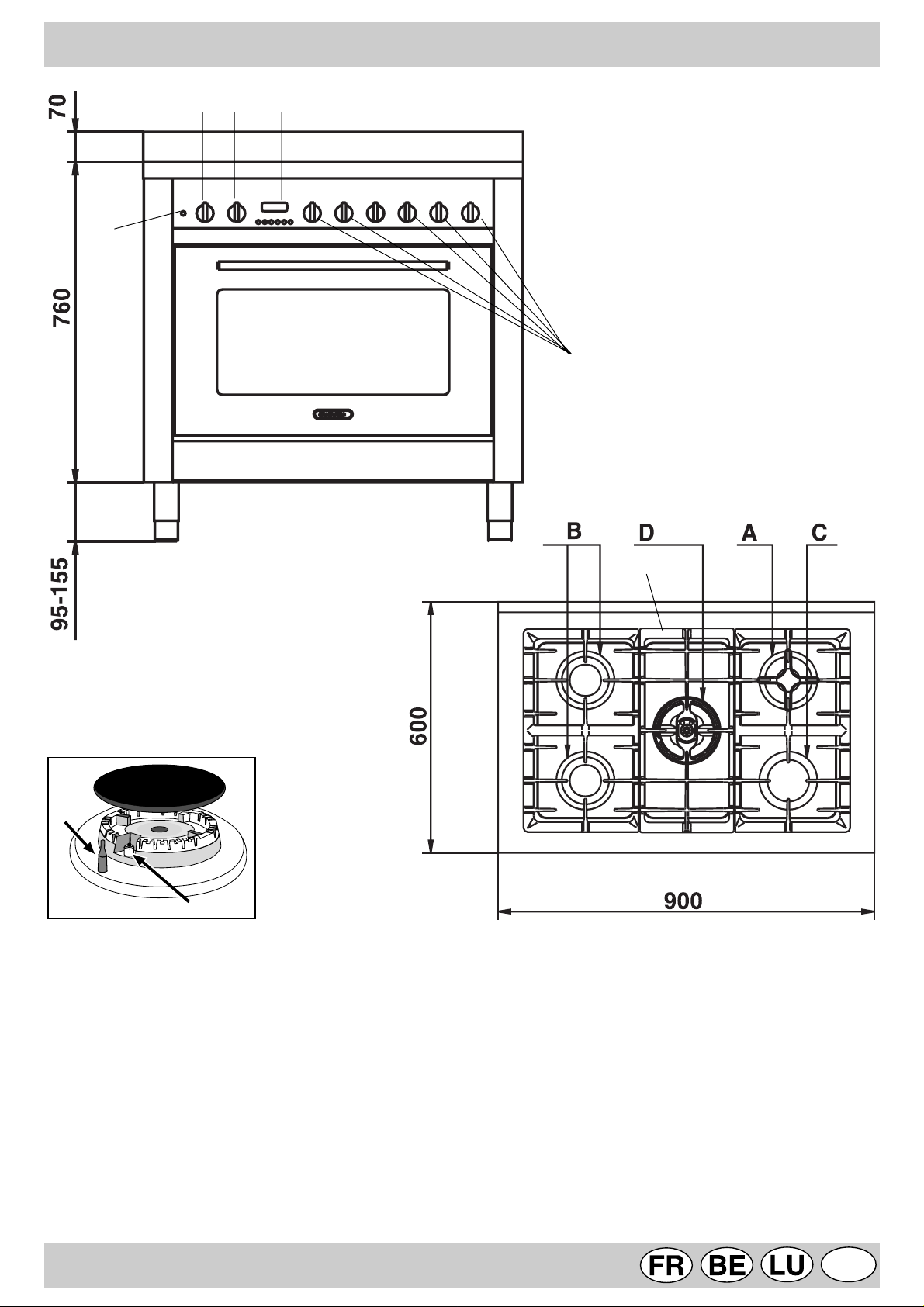
DESCRIPTION DE LA CUISINIÈRE
S
GH
T
M
F
E
A Brûleur gaz Auxiliaire
B Brûleur gaz Semi rapide
C Brûleur gaz Rapide
D Brûleur gaz DC-DR
R Grilles support de casseroles
M Manettes de commande des brûleurs gaz
E Bougie d'allumage des brûleurs gaz
F Dispositif de sécurité - Intervient en cas d'extinction
accidentelle de la flamme (débordement de liquides,
courants d'air, ...) en interrompant automatiquement
l'arrivée de gaz.
R
T Timer
S Voyant de fonctionnement du four électrique
G Manette commutateur du four électrique (sélecteur
types de cuisson)
H Manette thermostat du four électrique (sélection des
températures)
2
CH
Page 26
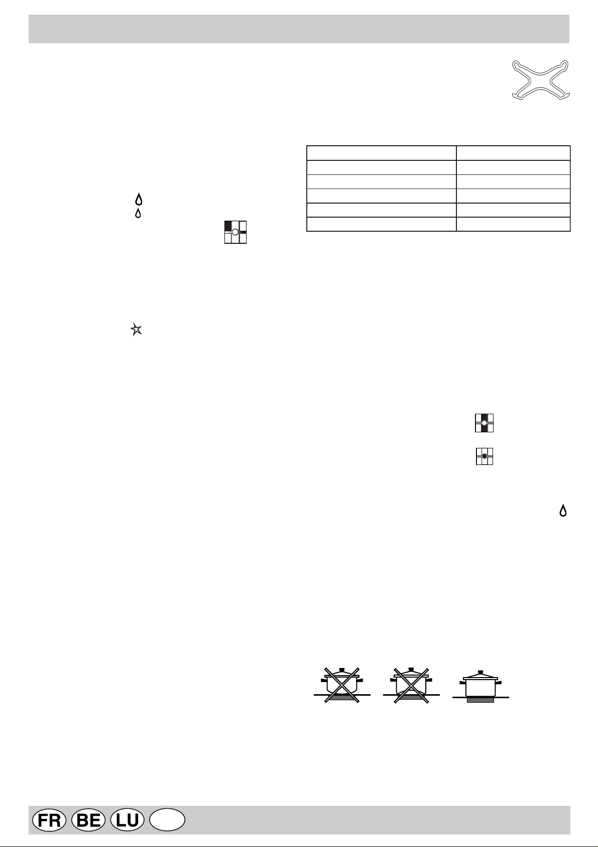
INSTRUCTIONS POUR L'UTILISATION
PLAN DE CUISSON
Le plan de cuisson est muni d’allumage automatique et
d’un dispositif de sécurité à thermocouple sur les brûleurs,
celui-ci permet de couper automatiquement la sortie du
gaz du brûleur en quelques secondes si la flamme s’éteint
accidentellement. Les brûleurs ont des dimensions et des
puissances différentes. Choisissez celui qui correspond
le mieux au diamètre de votre casserole.
Sur le tableau de commande, autour de chaque manette
"M", figurent les symboles:
Robinet fermé •
Ouverture maximale
Ouverture minimale
En outre, à côté des manettes les symboles indiquent
la position du brûleur correspondant sur le plan de cuisson.
Pour allumer un des brûleurs:
• tournez la manette correspondante dans le sens inverse
des aiguilles d’une montre afin de placer l’index en face
du symbole de la grande flamme;
• poussez à fond la manette afin d’actionner l’allumage
automatique du gaz ;
• maintenez la manette poussée pendant 10 secondes
environ avec la flamme allumée afin de permettre le
réchauffement du thermocouple de sécurité;
• relâchez la manette et assurez-vous que l’allumage s’est
bien fait de manière stable. Dans le cas contraire,
renouvelez l’opération.
Tournez la manette vers le symbole de la petite flamme
pour obtenir la puissance minimale. Il est possible de régler
la hauteur de la flamme en variant la position de la manette
entre les positions “grande flamme” et “petite flamme”. Pour
éteindre le brûleur, tournez la manette dans le sens des
aiguilles d’une montre et placez l’index en face de la position
de fermeture "•" .
Important:
• N'actionnez pas le dispositif d’allumage automatique
pendant plus de 15 secondes consécutives.
• Dans certains cas, les problèmes d’allumage peuvent
être dus à la présence d’air à l’intérieur de la canalisation
du gaz.
• Si la flamme d’un des brûleurs s’éteint accidentellement,
le gaz continue à s’échapper pendant quelques instants
avant l’intervention du dispositif de sécurité. Fermez la
manette de commande et attendez, par sécurité, au moins
1 minute avant de renouveler l’allumage pour permettre
à la fuite de gaz de se dissiper dans l'air.
• Lorsque le plan de cuisson n’est pas utilisé, contrôlez si
les manettes sont bien sur la position de fermeture "•". Il
est conseillé, en outre, de fermer le robinet de barrage
principal de la canalisation d’alimentation du gaz.
Utilisation des brûleurs:
Afin d’obtenir un rendement optimal des brûleurs,
choisissez un brûleur approprié au diamètre du récipient à
utiliser. Réglez la couronne de flammes pour qu’elle ne
déborde pas le pourtour du récipient (voir tableau ci-après).
Il est conseillé, en outre, de réduire la flamme dès qu’un
liquide commence à bouillir, juste ce qu'il faut pour maintenir
l’ébullition.
Le plan de cuisson est muni de deux grilles
de réduction (fig.1), qui peut être utilisées
sur le brûleur auxiliaire "A" et sur le brûleur
"D"(DC-DR intérieur).
fig.1
ruelûrB)mc(tneipicérudertèmaiDø
.AeriailixuA
.BedipaR-imeD
.CedipaR
.D)rueirétniRD-CD(semmalfxueD
.D)rueirétxeRD-CD(semmalfxueD
41–6
02–51
62–12
41-01
82-42
Le brûleur à "deux flammes indépendantes"
Ce brûleur à gaz est formé de deux anneaux de flamme
concentriques pouvant fonctionner ensemble ou séparément.
Leur utilisation conjointe à un réglage maximum permet
d'obtenir une puissance élevée qui réduit considérablement
les temps de cuisson par rapport aux brûleurs traditionnels.
Le double anneau de flamme permet de plus une distribution
plus uniforme de la chaleur sur le fond de la casserole, surtout
si vous utilisez les deux brûleurs à leur réglage minimum.
Vous pouvez utilisez des casseroles de toute dimension,
pour les plus petites n'allumez que le brûleur intérieur.
Chaque couronne composant le brûleur "deux flammes
indépendantes" a sa propre manette de commande :
la manette caractérisée par le symbole contrôle l'anneau
extérieur ;
la manette caractérisée par le symbole contrôle l'anneau
intérieur ;
Pour allumer l'anneau souhaité, appuyez à fond sur la
manette correspondante en tournant dans le sens inverse
des aiguilles d'une montre jusqu'à la position maximum .
Le brûleur est équipé d'un allumage électronique qui est activé
automatiquement par pression sur la manette.
Le brûleur étant équipé d'un dispositif de sécurité de
flamme "F", appuyez pendant au moins 6 secondes de
suite sur la manette pour permettre au dispositif de se
réchauffer.
Pour obtenir les meilleures performances de votre plan de
cuisson, il est important de suivre certaines règles
fondamentales pendant la cuisson et pendant la préparation
des aliments. Utilisez des casseroles à fond plat pour
qu’elles adhèrent parfaitement à la zone de chauffe
CH
3
Page 27

MAXIFOUR - COMMENT L'UTILISER
FOUR ÉLECTRIQUE MULTIFONCTIONS
Ce four permet de combiner les résistances électriques
entre elles dans neuf combinaisons différentes et de
choisir par conséquent celle qui convient le mieux à votre
plat en obtenant des résultats extrêmement précis. T ournez
la manette du sélecteur "G" repérable au symbole
pour obtenir les fonctions de cuisson indiquées dans le
tableau suivant:
elobmyS noitcnoF ecnassiuP
0
tnietE)0-
erueirépusecnatsiséR)1
erueiréfni+
W0532
erueiréfniecnatsiséR)2W0031
erueirépusecnatsiséR)3W0501
lirgecnatsiséR)4W0002
ecnatsiséR(lirgixaM)5
)erueirépus+lirg
lirgecnatsiséR(lirgixaM)6
noitalitnev+)erueirépus+
ecnatsiséR)7
noitalitnev+erueiréfni
ecnatsiséR)8
noitalitnev+erialucric
W0503
W0013
W0531
W0582
ediparnoitalégnocéD)9W05
Choisissez la fonction de cuisson et amenez ensuite le
symbole de la manette du thermostat "H" en face de
la température désirée.
• La cuisson au
très élevée qui permet de saisir immédiatement les
aliments en surface; elle est donc conseillée pour la
viande dont le coeur doit rester tendre.
Pour cuire au gril tournez la manette du sélecteur “H” en
face d'une des positions suivantes (gril),
(maxigril), (maxigril + ventilateur).
Pendant le fonctionnement du gril, laissez toujours
la porte du four fermée et placez la manette du
thermostat sur une température ne dépassant pas
200°C.
Eclairage du four
L’éclairage du four est automatique dès que le sélecteur
est placé sur n’importe quelle position.
V oyant de signalisation "S"
Ce voyant indique que le four est en train de chauffer et il
s’éteint dès que le four atteint la température sélectionnée
au moyen du bouton.
A présent, le voyant s’allume et s’éteint alternativement, il
indique ainsi que le thermostat marche correctement pour
garder la température du four constante.
T ournebrochettes - Tournebroche
Cet accessoire ne doit être utilisé que pour les cuissons
avec le brûleur du grilloir.
Enfilez les pièces de viande à rôtir sur la broche
transversale, dans le sens de la longueur, en les bloquant
au moyen des fourchettes réglables prévues à cet effet
(fig.2a).
Placez les supports “A” et “B” (fig.2b) dans les orifices
prévus sur la lèchefrite “E”, déposez le col de la broche
dans le logement “C” et insérez la grille dans la première
glissière dans le bas du four; enfilez ensuite la broche dans
l’orifice du tournebroche, en déplaçant vers l’avant le col
dans le logement “D”.
Mettez la manette du sélecteur sur les positions suivantes:
.
gril
exige une puissance de chauffage
• Pour des cuissons traditionnelles en mode
conventionnel
(chaleur dessus+dessous).
Avant d'enfourner vos plats, sur un seul niveau de
préférence, attendez que le four ait atteint la température
sélectionnée. Si vous ne voulez de chaleur qu'en dessus
ou qu'en dessous de vos plats, amenez le sélecteur en
face de la position (chaleur dessous), (chaleur
dessous + ventilation) ou bien (chaleur dessus).
• Dans la fonction (
chauffé par une résistance et brassé par un ventilateur
à l'intérieur du four qui assure la cuisson. La montée en
chaleur est très rapide et les plats peuvent par
conséquent être enfournés dès l'allumage du four. Vous
pouvez aussi cuire sur deux niveaux en même temps.
• La fonction “
élément chauffant mais uniquement la lampe du four et
la ventilation.
(rôtis, biscuits, etc.) utilisez la fonction
chaleur tournante
décongélation rapide
” n'utilise aucun
) c'est l'air
AB
fig. 2a fig. 2b
4
CH
Page 28

COMMENT LE GARDER EN FORME
Avant toute opération de nettoyage ou d'entretien
coupez l'alimentation électrique de l'appareil.
Pour prolonger la durée de vie de votre appareil, nettoyezle fréquemment, en n'oubliant pas que:
• les panneaux autonettoyants (si votre appareil en est
équipé) ainsi que les parties émaillées doivent être lavés
à l'eau tiède en évitant toute utilisation de poudres
abrasives ou de produits corrosifs;
• l’intérieur du four doit être nettoyé, après toute utilisation,
quand il est encore tiède avec de l'eau chaude et du
détergent, en rinçant et en essuyant ensuite
soigneusement;
• des taches peuvent se former sur l'acier inox si ce
dernier reste trop longtemps au contact d'une eau
fortement calcaire ou de détergents agressifs (contenant
du phosphore). Il est conseillé de rincer abondamment
et d'essuyer après le nettoyage. Il vaut également mieux
essuyer tout débordement d'eau;
• n'habillez jamais le fond de votre four avec du papier
alu, car l'accumulation de chaleur qui s'en suivrait
compromettrait non seulement la cuisson mais
endommagerait aussi l'émail.
Remplacement de la lampe à l'intérieur du four
• Coupez l'alimentation du four à l'aide de l'interrupteur
omnipolaire reliant le four à l'installation électrique ou
bien débranchez la fiche, si elle est accessible;
• Dévissez le couvercle en verre de la douille;
• Dévissez la lampe et remplacez-la par une autre
résistant aux températures élevées (300°C) et ayant
les caractéristiques suivantes:
- T ension 230/240 V
- Puissance 15W
- Culot E14
• Remontez le couvercle en verre et rebranchez le four.
Démontage/montage de la porte du four
Pour faciliter le nettoyage à l’intérieur du four, vous pouvez
démonter la porte du four en procédant comme suit (fig.3-
4) :
• Ouvrez complètement la porte et soulevez les 2 leviers
“B” (fig. 3) ;
• Fermez à présent partiellement la porte et soulevez-la
en dégageant les crochets “A” comme illustré figure 4.
Pour remonter la porte :
• Tenez la porte en position verticale, introduisez les 2
crochets “A” dans les fentes ;
• Vérifiez que l’encoche “D” soit bien insérée sur le bord
de la fente (déplacez légèrement la porte en avant et en
arrière) ;
• Porte complètement ouverte, décrochez les 2 leviers “B”
vers le bas, puis fermez la porte.
fig 3
CH
fig 4
5
Page 29

PROGRAMMA TEUR ÉLECTRONIQUE
Le programmateur électronique se charge de mettre en
marche le four automatiquement et de l’arrêter à la fin du
temps de cuisson préétabli. L’af ficheur lumineux à 4 chiffres
indique l’heure du jour et les temps de programmation, et
visualise en outre l’état du four par les symboles suivants:
Four en marche
Minuterie
Programme automatique AUTO
Point • (sépare l’heure des minutes sur l’afficheur)
Toutes les fonctions peuvent être programmées pour un
temps total de 23 h et 59 min. La durée maximale de
cuisson programmable est de 10 heures.
Mise à l’heure de l’horloge
(Lors de l’installation du four, après une coupure de courant,
pour avancer ou reculer l’heure).
Sélectionnez la fonction manuelle en appuyant sur la
touche réglez l’heure au moyen des touches - et +.
Fonctionnement manuel du four (Sans l’aide du
programmateur)
Appuyez sur la touche ; le four est à nouveau branché
électriquement, le symbole AUTO s’éteint et le symbole
(four en marche) s’allume. Cette opération efface un
éventuel programme déjà introduit.
Fonctionnement semi-automatique du four
1er cas: début de cuisson manuel - temps de cuisson
programmé
• Enfournez les aliments à cuire.
• Appuyez sur la touche (Durée) et réglez la durée
de cuisson à l’aide des touches - et +: le four se bran-
che ainsi électriquement, les symboles AUTO et (four
en marche) s’allument.
• Tournez les boutons du sélecteur et du thermostat
respectivement sur la fonction et sur la température
souhaitée.
• A la fin de la cuisson, le four s’arrêtera automatiquement,
le symbole (four en marche) s’éteindra et le symbole
AUTO clignotera; un signal sonore se déclenchera.
2ème cas: début de cuisson manuel - fin de cuisson
programmée
• Enfournez les aliments à cuire.
• Appuyez sur la touche (Fin de cuisson) et réglez
l’heure de fin de cuisson à l’aide des touches - et + ;le
four se branche ainsi électriquement, les symboles
AUTO et s’allument.
• Tournez les boutons du sélecteur et du thermostat
respectivement sur la fonction et sur la température
souhaitée.
· A la fin de la cuisson, le four s’arrêtera automatiquement,
le symbole (four en marche) s’éteindra et le symbole
AUTO clignotera; un signal sonore se déclenchera.
Fonctionnement automatique du four (Durée et fin de
cuisson programmées)
• Enfournez les aliments à cuire.
• Appuyez sur la touche (Durée) et réglez la durée
de cuisson à l’aide des touches - e + : le four se bran-
che ainsi électriquement, le symbole AUTO et le
symbole (four en marche) s’allument.
• Appuyez sur la touche (Fin de cuisson) et réglez
l’heure de fin de cuisson à l’aide des touches - e + ; le
four se débranche ainsi électriquement et le symbole
(four en marche) s’éteint.
• Tournez les boutons du sélecteur et du thermostat
respectivement sur la fonction et sur la température
souhaitée.
• Le programmateur règle automatiquement l’heure de
début de cuisson, qui est visualisée par l’allumage du
symbole (four en marche). A la fin du temps de
cuisson, le four se débranchera automatiquement, le
symbole s’éteindra et le symbole AUTO clignotera;
un signal sonore se déclenchera.
Minuterie
Appuyez sur la touche (minuterie) et réglez le temps
souhaité à l’aide des touches - et + . Le signal sonore
annoncera la fin du temps programmé.
Signal sonore
Le signal sonore retentit pendant 7 minutes après la fin du
programme sélectionné; pour l’arrêter, appuyez sur
n’importe quelle touche fonction. 3 types de signal sonore
avec des tonalités différentes sont disponibles. En appuyant
sur la touche - il est possible d’écouter le signal
actuellement sélectionné. En appuyant à nouveau sur la
touche - dans les 7 secondes qui suivent, on peut choisir
un autre signal sonore.
Contrôle du programme
Appuyez sur la touche pour visualiser le temps restant,
sur la touche pour vérifier l’heure de fin de cuisson.
Elimination du programme
Le programme s’effacera automatiquement dès qu’il sera
terminé, ou en appuyant sur la touche (manuel).
6
CH
Page 30

CONSEILS PRATIQUES POUR LA CUISSON
Préchauffage
Quand il faut préchauffer le four, en gros chaque fois que
vous devez enfourner des pâtes levées, vous pouvez utiliser
la fonction “ventilé” qui permet d'atteindre la
température désirée trés rapidement tout en réduisant la
consommation d'énergie. Une fois que vous avez enfourné,
vous pouvez passer à la fonction de cuisson la plus
indiquée.
Utilisation du gril
Utilisez la position “gril”, mais vous obtenez un résultat
parfait pour de petites pièces comme des croque-monsieur,
des saucisses de Strasbourg etc...
Placez votre plat au milieu de la grille, car seule la partie
centrale de la résistance du haut est branchée, les aliments
placés dans les coins ne sont pas cuits.
La position “gril ventilé” est extrêmement utile pour
des grillades rapides, la chaleur produite par le gril bien
distribuée permet de dorer en surface et de cuire en
dessous aussi.
Vous pouvez vous en servir pour parfaire la cuisson
d'aliments ayant besoin de dorer en surface, c'est l'idéal
par exemple pour dorer vos gratins de pâtes en fin de
cuisson.
Important: lors de la cuisson au gril, la porte du four
doit être fermée, vous obtiendrez ainsi de meilleurs
résultats et ferez des économies d'énergie (10% environ).
Pour vos cuissons au gril, nous vous conseillons de régler
la manette du thermostat en position maximum (200°C),
car c’est celle qui permet d’obtenir un rendement optimal
qui se base sur l’action des rayons infrarouges; placez la
grille sur les gradins du haut (consultez le tableau de
cuisson) et, pour recueillir la graisse qui coule et éviter la
formation de fumée, placez la lèchefrite sur le premier
étage en partant du bas.
Cuisson de la pâtisserie
Enfournez toujours vos gâteaux à four chaud, attendez
que l'extinction du voyant rouge “S” vous signale que le
préchauffage est terminé. N'ouvrez pas la porte en cours
de cuisson, votre gâteau risquerait de s'affaisser.
Les pâtes molles ne doivent pas être trop fluides, pour ne
pas trop prolonger les temps de cuisson. En général:
Pâtisse rie trop sè che
La prochaine fois programmez une température de
10°C supérieure et réduisez le temps de cuisson.
Bonne cui sson exté rieure, mais in tér ieur collant
Utilisez moins de liquide, abaissez la température,
augmentez le temps de cuisson.
Le gâtea u ne se dé t ache pa s du moule
Beurrez bien le moule et saupoudrez-le de panure ou
de farine.
J’ai cui t sur pl usieurs ni veaux mais ils ne sont pas
tous a u même degré de cuisson
Choisissez une température plus bas se. Des niveaux
enfournés simultanément ne doivent pas
obligatoirement être sor ti s ensemble.
Cuisson de la pizza
Pour une bonne cuisson de la pizza utilisez la fonction
“ventilé”:
• Préchauffez le four pendant au moins 10 minutes
• Utilisez un plat en aluminium léger, posez-le sur la
grille du four. Si vous utilisez la lèche-frite vous
prolongerez le temps de cuisson et vous obtiendrez
difficilement une pizza croustillante.
• N'ouvrez pas souvent le four pendant la cuisson
• Si vos pizzas sont bien garnies ("capricciosa", "quattro stagioni") ne mettez la mozzarelle qu'à mi-cuisson.
Cuisson du poisson et de la viande
La viande doit peser au moins 1 Kg. pour éviter qu'elle ne
se dessèche trop. Pour les viandes blanches, les volailles
et le poisson, utilisez des températures basses
(150°C-200°C). Pour les viandes rouges que l'on désire
bien cuites à l'extérieur mais juteuses à l'intérieur, il vaut
mieux commencer par une température élevée
(200°C-220°C) pendant un bref laps de temps et l'abaisser
ensuite. En général, plus le rôti est gros, plus la
température doit être basse et la durée de la cuisson
prolongée. Posez la viande au centre de la grille et placez
la lèchefrite sous la grille pour recevoir la graisse qui
s'écoule. Enfournez la grille de manière à ce que la pièce
à cuire se trouve au centre du four. Si vous désirez plus
de chaleur par le bas, utilisez les gradins les plus bas.
Pour obtenir des rôtis plus savoureux (c'est le cas
notamment pour le canard et le gibier) bardez votre viande
et placez-la dans le haut du four.
Le gâteau s'affaisse
Utilisez moins de liquide ou baissez la température de
10°C.
Gâtea u foncé sur le dessus
Enfournez-le à un niveau plus bas, choisissez une
température plus basse et prolongez l a cui sson
CH
7
Page 31

CONSEILS POUR LA CUISSON
Les temps de cuisson peuvent varier en fonction de la nature des aliments, de leur homogénéité et de leur volume. Il est
donc conseillé de choisir, lors de la première cuisson, les valeurs les plus basses parmi les temps de cuisson indiqués
et de les augmenter par la suite si nécessaire.
Cuisson au four ST ATIQUE
edspmeT
nossiuc
)setunim(
07-06
04-03
03-02
05-04
05-04
04-03
05-04
02-51
02-51
02-51
02-51
edniD)gk8-4(
eiO)gk5-4(
teluoP)gk½1-1(
Cuisson au GRIL
)gk6.0(ehcorbalàuaeveditôR
steM
sednaiV
dranaC)gk4-2(
nopahC)gk3-½2(
ésiarbfueoB)gk½1-1(
uaenga'dtogiG
oitôrervèiL)gk2(
itôrnasiaF
nossioP
edspmeT
nossiuc
)setunim(
06
51
06
06
06
C°
061
061
071
071
061
061
061
061
071
002
ednoitisoP
ellirgal
nidargemè3
nidargemè2
La 1ère glissière indique la glissière
nidargre1
-
-
située dans la position la plus
basse.
erutarépmeT
edspmeT
nossiuc
½4-3
½4-4
½2-½1
½2-2
½3-3
½1-1
½1-1
½1-1
½1-1
itunim52-51
steM
eiressitâP
stiurfxuaetraT
seugnireM
senêGedniaP
esionêG
xuohC
eételliuef
egnA'leduaetâG
essaguoF
elliuef-elliM
eésirbetâP
talocohcuauaetâG
etâpnestiucsiB
sessicuaS
C°
031
031
051
061
061
071
071
002
002
002
002
erutarépmeT
steM
)gk5.0(setteletôC
)gk1(éllirgteluoP
)gk1(ehcorbalàteluoP
Cuisson au four à CHALEUR TOURNANTE
eiressitâP
xuaetâgstiteP
ednaiV
uaeV
fueoB
croP
teluoP
uaeV
fueoB
croP
teluoP
dranaC
sésiarB
ésiarbfueoB
ésiarbuaeV
snossioP
sertîuH
sénisiucstalP
ednaiV
ednaiV
ednaiV
steM
eluomne,eétteuofetâpcevA*
eluomsnas,eétteuofetâpcevA*
etrateddnof,eésirbetâP
edimuhecrafcevaeésirbetâP
ehcèsecrafcevaeésirbetâP
lerutanegavelàetâpcevA*
nidarg°N
tnatrapne
sabud
3-1
4-3-1
4-3-1
3-1
4-3-1
3-1
4-3-1
ellirgalrusstiucsitôR
2
esialgna'làfibsoR
talpnestiucsitôR
esialgna'làfibsoR
sehcnartneedniD
elos,nalrem,niloc,sehcnart,steliF
nomuas,tobrut,uaereuqaM
snitargtesélffuoS
setâpednitarG
semugélednitarG
sélastesércussélffuoS*
snossuahcteazziP*
rueisnom-euqorC
noitalégnocéD
2
2
2
2
3-1
3-1
3-1
3-1
3-1
3-1
1
1
3-1
3.1
3-1
3-1
3-1
3-1
4-3-1
4-3-1
3-1
3-1
3-1
3-1
étitnauQ
gk
1
1
5.0
5.1
1
1
5.0
1
1
1
1
5.1-1
1
1
1
5.1-1
5.1
5.1-1
1
1
1
1
2
2
57.0
5.0
5.0
1
5.0
57.0
1
C°
erutarépmeT
571
571
571
571
571
571
061
081
081
022
081
002
061
061
061
081
081
081
571
571
081
081
081
581
581
081
002
091
002
05
05
05
Remarques:
1) Les temps de cuisson indiqués ne comprennent pas le préchauffage du four, à l’exception de ceux repérés par un astérisque.
2) La position de la grille sur les gradins, indiquée dans le tableau, est celle optimale pour la cuisson sur plusieurs niveaux.
3) Les temps indiqués se référent à la cuisson sur un seul niveau; pour plusieurs niveaux, augmentez le temps de cuisson de 5-10 minutes.
4) Dans le cas de rôtis de viande de boeuf, veau, porc et dinde avec os ou roulés, augmentez le temps de cuisson de 20 minutes.
spmeT
-tunim
se
06
05
03
07
54
05
03
06
07
05
07
07
08
09
09
09
021
021
021
011
03
54
02
06
05
05
03
51
54
05
07
011
8
CH
Page 32

INSTRUCTIONS POUR L'INSTALLATION
Les instructions qui suivent s’adressent à l’installateur
qualifié afin qu’il exécute les opérations d’installation,
réglage et entretien technique conformément aux normes
en vigueur.
Important: avant d’effectuer toute opération de réglage,
entretien, etc., assurez-vous que l'appareil soit
déconnecté électriquement. Si l’appareil doit
obligatoirement rester sous tension, il faudra prendre toutes
les mesures de précaution nécessaires. La cuisinière a
les caractéristiques techniques suivantes:
-Classe 1 Catégorie II 2E+3+ (FRANCE et BELGIQUE)
Catégorie I2E (G20 LUXEMBOURG)
Catégorie I3+ (G30-G31 LUXEMBOURG)
Catégorie II 2H3+ (SUISSE)
Les dimensions de la cuisinière sont indiquées figure page
2. Afin de garantir le parfait fonctionnement de l’appareil
installé à côté des meubles, il est indispensable de
respecter les distances minimales indiquées à la fig.5. En
outre, les surfaces adjacentes et la paroi arrière doivent
être en mesure de résister à une surchauffe de 65°C.
Ventilation de la cuisine
Il est indispensable que la pièce où l’appareil est installé
dispose d'une quantité d’air égale à la quantité nécessaire
pour une bonne combustion du ga et l’aération de la
pièce. L’af flux naturel de l’air doit se produire à travers des
ouvertures permanentes réalisées dans les murs de la
pièce qui donnent vers l’extérieur, ou bien des conduits de
ventilation individuels ou collectifs ramifiés, conformes aux
normes en vigueur. L’air de ventilation doit être prélevé
directement de l’extérieur, dans une zone loin de sources
de pollution. L’ouverture d’aération devra avoir les
caractéristiques suivantes (fig.8A):
• avoir une section libre totale nette de passage de 6 cm²
au moins pour chaque kW de débit thermique nominal
de l’appareil, avec un minimum de 100 cm² (le débit
thermique est indiqué sur la plaquette signalétique);
• être réalisée de manière à ce que les bouches
d’ouverture, aussi bien à l’intérieur qu’à l’extérieur du
mur, ne puissent pas être obstruées;
• être protégée par exemple par des grilles, treillis
métallique, etc. de façon à ne pas réduire la section utile
susmentionnée;
• être située à une hauteur proche du niveau du sol.
fig.6
fig.5
Avant d'installer la cuisinière, fixez les pieds support de
95÷155 mm de haut (fournis avec l'appareil) dans les trous
prévus dans le bas de la cuisinière (fig.6). Ces pieds sont
réglables au moyen de vis, ils permettent par conséquent
de mettre la cuisinière à niveau en cas de besoin.
Positionnement
Cet appareil ne peut être installé et utilisé que dans un
local toujours parfaitement aéré conformément aux normes
en vigueur. Les conditions essentielles suivantes doivent
être respectées:
• L’appareil doit évacuer les produits de la combustion dans
une hotte prévue à cet effet qui doit être raccordée à une
cheminée, à un carneau ou directement à l’extérieur
(fig.7).
• Si l’installation de la hotte n’est pas possible, il est permis
d’installer un électroventilateur, sur une fenêtre ou sur
un mur donnant vers l’extérieur, qui devra être mis en
marche en même temps que le plan de cuisson.
fig.7
En cas de cheminée ou conduit de fumée ramifié Directement à l'extérieur
(réservé aux appareils de cuisson)
Détail A Local Local à
adjacent ventiler
A
Exemples d'ouverture de ventilation Agrandissement de la fissure
pour l'air comburant entre la porte et le sol
Fig. 8A Fig.8B
L’af flux de l’air peut provenir également d’une pièce voisine
pourvu que cette pièce ne soit pas une chambre à coucher
ou une pièce à risque d’incendie telle que débarras, garage,
dépôt de matériaux combustibles, etc., et qu’elle soit
ventilée conformément aux normes en vigueur. Le flux d’air
de la pièce voisine jusqu’à la pièce à ventiler peut se
produire librement à travers des ouvertures permanentes,
ayant une section non inférieure à celle susmentionnée.
Ces ouvertures pourront également être réalisées en
agrandissant la fissure entre la porte et le sol (fig.8B). Si
on utilise un électroventilateur pour l’évacuation des
produits de la combustion, l’ouverture de ventilation devra
être augmentée en fonction du débit d’air maximal de ce
dernier. L’électroventilateur devra avoir un débit suffisant
à garantir, pour la pièce de la cuisine, un renouvellement
horaire d’air égal à 3-5 fois son volume. Une utilisation
intensive et prolongée de l’appareil peut exiger une aération
supplémentaire, par exemple l’ouverture d’une fenêtre ou
une aération plus efficace en augmentant la puissance
d’aspiration de l’électroventilateur s’il existe. Les gaz de
pétrole liquéfiés, plus lourds que l’air, stagnent vers le
bas. Par conséquent, les pièces contenant des bouteilles
de GPL doivent disposer d’ouvertures vers l’extérieur au
niveau du sol afin de permettre l’évacuation à partir du
CH
9
Page 33

INSTRUCTIONS POUR L'INSTALLATION
bas d'éventuelles fuites de gaz. En outre, ne jamais stocker
des bouteilles de GPL (même vides) dans des locaux
souterrains. Il est opportun de conserver dans la pièce
uniquement la bouteille de gaz utilisée, raccordée loin de
sources de chaleur qui risqueraient d’en augmenter la
température au-delà de 50 °C.
Raccordement à la canalisation du gaz
• Le raccordement de l’appareil à la canalisation du gaz ou
à la bouteille de gaz doit être effectué en conformité avec
les règlements en vigueur et après avoir vérifié que
l’appareil soit bien réglé pour ce type de gaz.
• Cet appareil est prédisposé pour fonctionner avec le gaz
indiqué sur l’étiquette apposée sur le plan de cuisson. Si
le plan de cuisson doit être raccordé à un gaz différent
du type de gaz indiqué sur l’étiquette, il faudra remplacer
les injecteurs (en dotation) en respectant les instructions
du paragraphe “Adaptation aux différents types de gaz”.
• Afin de garantir un fonctionnement sûr, un usage approprié
de l’énergie et une plus longue durée de l’appareil, vérifiez
que la pression d’alimentation corresponde aux valeurs
indiqués sur le tableau 1 “Caractéristiques des brûleurs
et des injecteurs”, dans le cas contraire installez sur la
canalisation d’arrivée du gaz un régulateur de pression
spécial conforme aux normes en vigueur.
• Effectuez le raccordement de manière à ne pas provoquer
de sollicitations d’aucune sorte sur l’appareil.
Réalisez le raccordement au raccord orientable (fileté ½G
mâle) situé sur le côté arrière droit de l’appareil (fig.9), au
moyen d’un tuyau métallique rigide et de raccords
conformes aux normes en vigueur, ou au moyen d’un tuyau
flexible métallique conforme aux normes en vigueur, dont
l’extension maximale ne devra pas dépasser 2000 mm. Si
le raccord doit être tourné, remplacez obligatoirement le
joint d’étanchéité (fourni avec l’appareil).
A la fin du travail de montage, assurez-vous que l’étanchéité
du circuit gaz, des connexions internes et des robinets
soit parfaite en utilisant de l’eau savonneuse (n’utilisez
jamais une flamme!). Vérifiez en outre que le tube de
raccordement ne puisse entrer en contact avec des parties
mobiles risquant de l’abîmer ou de l’écraser. Assurez-vous
que la canalisation du gaz naturel soit suffisante pour
alimenter l’appareil quand tous les brûleurs sont allumés.
Important: Pour effectuer le raccordement avec du gaz
liquide (en bouteille), interposez un régulateur de pression
conforme aux normes en vigueur.
• enlever les grilles de le plan de cuisson et sorter les
brûleurs de leur logemen.
• dévisser les injecteurs à l’aide d’une clé à tube de 7 mm.
(fig.10) et les remplacer par les injecteurs appropriés au
nouveau type de gaz (cf.tableau 1 “Caractéristiques des
brûleurs et des injecteurs”.
• remonter les différentes parties en effectuant les
opérations dans le sens inverse.
• en fin d’opération, remplacez l’ancienne étiquette de
calibrage par la nouvelle, correspondant au nouveau
gaz utilisé, que vous trouverez dans nos centres de
Service Après-vente.
A
fig.10
Réglage des minima
• Placer le robinet sur la position minimum;
• enlevez la manette du robinet et effectuez le réglage au
moyen de la vis de réglage située à côté de la tige du
robinet (fig.11) en utilisant un tournevis (en dévissant la
vis le minimum augmente, tandis qu’en la vissant il
diminue) remarque: dans le cas de gaz liquide, la vis de
réglage doit être vissée à fond;
• une fois obtenu le débit minimal souhaité, allumez le
brûleur et tournez brusquement la manette de la position
de ralenti à la position d’ouverture maximale et vice versa à plusieurs reprises. Vérifiez ainsi qu’il n’y ait pas
extinction du brûleur.
Remplacement des injecteurs sur le brûleur "deux
flammes" indépendantes :
• enlevez les grilles du plan de cuisson et sortez les
brûleurs de leur logement ; Le brûleur est formé de deux
parties distinctes (voir Fig. C et Fig. D) ;
• dévissez les injecteurs à l'aide d'une clef en tube de 7
mm. Le brûleur intérieur a un injecteur, le brûleur
extérieur en a deux (de même dimension). Remplacez
les injecteurs par d'autres appropriés au nouveau type
de gaz (voir tableau 1).
• remontez les différentes parties en effectuant les
opérations dans le sens inverse.
fig.11
Adaptation à un différent type de gaz
Pour adapter le plan à un type de gaz différent de celui
pour lequel il a été conçu (indiqué sur la plaquette fixée
sous le plan ou sur l'emballage) remplacer les injecteurs
de tous les brûleurs et, pour ce faire, procéder comme
suit:
fig.9
Fig. C Fig. D
Réglage de l’air primaire des brûleurs
(Pour la France et la Belgique)
Les brûleurs ne nécessitent d’aucun réglage de l’air
primaire.
10
CH
Page 34

BRANCHEMENT ÉLECTRIQUE
L’APPAREIL DOIT NECESSAIREMENT ÊTRE RELIÉ A LA
TERRE.
Le plan est prédisposé pour fonctionner en courant alternatif
à la tension et fréquence d’alimentation indiquées sur la
plaquette signalétique (située en dessous du plan ou aux
dernière page du livret). Assurez-vous que la tension
d’alimentation du réseau corresponde bien à la tension
indiquée sur la plaquette signalétique.
Branchement du câble d’alimentation électrique au
réseau
Pour les modèles qui ne sont pas munis de fiche, montez
sur le câble une fiche normalisée pour la charge indiquée
sur la plaquette signalétique et reliez-la à une prise de
courant appropriée. Si vous désirez effectuer un
branchement direct au réseau, il est nécessaire d’interposer
entre l’appareil et le réseauun interrupteur à coupure
omnipolaire, ayant une distance minimale d’ouverture des
contacts de 3 mm, proportionnel à la charge et conforme
aux normes en vigueur. Le conducteur de mise à la terre
jaune/vert ne doit pas être interrompu par l’interrupteur. Le
câble d’alimentation doit être placé de façon à ce qu’il
n’atteigne en aucun point une température supérieure de
50 °C à la température ambiante.
Dans le cas d’installation au-dessus d’un four encastrable,
le branchement électrique de le plan et celui du four doivent
être réalisés séparément, tant pour des raisons de sécurité
électrique que pour faciliter l’extractibilité du four. Ne pas
utiliser de réducteurs, adaptateurs ou shunts qui pourraient
entraîner des surchauffes ou brûlures. Avant d’effectuer le
branchement, assurez-vous que:
• la soupape de limitation et l’installation électrique
domestique soient en mesure de supporter la charge de
l’appareil (voir la plaquette signalétique);
• l’installation soit équipée d’une mise à la terre efficace
conformément aux normes et aux dispositions des lois
en vigueur;
• la prise ou l’interrupteur omnipolaire soient aisément
accessibles quand l’appareil est installé.
NOTRE RESPONSABILITÉ NE SAURAIT ÊTRE ENGAGÉE
SI LES NORMES EN MATIÈRE DE PREVENTION DES
ACCIDENTS NE SONT PAS RESPECTÉES.
Remplacement du câble
Utilisez un câble en caoutchouc du type H05VV-F ayant
une section 3 x 1.5 mm². Le conducteur de mise à la terre
jaune/vert devra être plus long de 2-3 cm par rapport aux
autres conducteurs.
CARACTÉRISTIQUES DES BRÛLEURS ET DES INJECTEURS
1uaelbaT sediuqilzaGslerutanzaG
RUELÛRB
.CedipaR
.B edipar-imeD
.AeriailixuA
.D )rueirétniRD-CD(semmalfxueD
.D )rueirétxeRD-CD(semmalfxueD
ertèmaiD
ruelûrb
)mm(
00100.37.00468812412611682233
5756.14.0034602181169751381
5500.13.0720537171759011
0309.04.0034456460768001
03101.43.17507892392011093454
)RF(noitatnemilaednoisserP 03-82730252
)EB(noitatnemilaednoisserP 03-82730252
)UL(noitatnemilaednoisserP 03-827302
ecnassiuP
euqimreht
)*.s.H(Wk
.moN.deR
ssap-yB
001/1
)mm(
ruetcejnI
001/1
)mm(
*tibéD
h/g
03G13G02G52G
ruetcejnI
001/1
)mm(
*tibéD
h/l
)HC(noitatnemilaednoisserP 03-827302
* A 15°C et 1013 mbar-gaz sec
Propane G31 H.s. = 50,37 MJ/kg
Butane G30 H.s. = 49,47 MJ/kg
Méthane G20 H.s. = 37,78 MJ/m
Méthane G25 H.s. = 32,49 MJ/m
CH
Cet appareil est conforme aux Directives
Communautaires suivantes:
3
3
- 73/23/CEE du 19/02/73 (Basse T ension) et modifications
successives;
- 89/336/CEE du 03/05/89 (Compatibilité
électromagnétique) et modifications successives;
- 90/396/CEE du 29/06/90 (Gaz) et modifications
successives;
- 93/68/CEE du 22/07/93 et modifications successives.
11
Page 35

Wir danken Ihnen, dass sie dieses sichere und wirklich leicht zu bedienende Ariston-Gerät gewählt haben. Um sich mit
diesem vertraut zu machen und es auf optimale Art zu gebrauchen lernen, empfehlen wir Ihnen, dieses Handbuch
aufmerksam durchzulesen. Danke.
HINWEISE
DIESE ANLEITUNGEN GELTEN NUR FÜR DIE BESTIMMUNGSLÄNDER, DEREN SYMBOLE IM HANDBUCH UND
AUF DEM TYPENSCHILD DES GERÄTES ABGEBILDET SIND.
1. Dieses Gerät wurde für den Einsatz nicht
professioneller Art in Haushalten konzipiert.
2. Lesen Sie bitte die in diesem Handbuch enthaltenen
Hinweise aufmerksam durch, da sie wichtige
Angaben hinsichtlich der Sicherheit bei der
Installation, dem Gebrauch und der Wartung liefern.
Bewahren Sie dieses Handbuch sorgfältig auf, um
es jederzeit zu Rate ziehen zu können.
3. Die mit Lebensmitteln eventuell in Berührung
kommenden Backofenzubehörteile bestehen aus
Materialien, die den Vorschriften der EG-Richtlinien 89/
109 vom 21.12.88 und der Rechtsverordnung 108 vom
25.01.92 entsprechen.
4. Nach Entfernen der Verpackung überzeugen Sie sich
bitte von der Unversehrtheit des Gerätes. Im
Zweifelsfall raten wir, das Gerät nicht zu benutzen und
sich an Fachpersonal zu wenden.
5. Um Kratzer zu vermeiden, wurden einige T eile mit einem
abnehmbaren Schutzfilm überzogen. Vor
Inbetriebnahme des Gerätes muß dieser Film entfernt
werden, die geschützten Teile sind daraufhin mit einem
weichen Tuch und einem milden Reinigungsmittel zu
reinigen. Verwenden Sie hierzu bitte keine
Scheuermittel. Es empfiehlt sich, den Backofen vor
erstmaligem Benutzen für etwa 30 Minuten auf
Höchsttemperatur in Betrieb zu setzen, um eventuelle
Fertigungsrückstände zu beseitigen.
6. Die zur Installation und Einstellung erforderlichen
Arbeiten sind gemäß den einschlägigen Richtlinien und
ausschließlich durch Fachpersonal durchzuführen.
Hinsichtlich der entsprechenden, spezifischen
Anleitungen verweisen wir auf den für den Installateur
bestimmten Teil des Handbuches.
7. Vor Anschluß des Gerätes kontrollieren Sie bitte, daß
die auf dem Typenschild (befindlich auf dem unteren
Geräteteil und auf der letzten Seite des Handbuchs)
angegebenen Daten mit denen des Strom- und
Gasversorgungsnetzes übereinstimmen.
8. Bei in Betrieb befindlichem Backofen oder Grill könnten
das Backofenfenster und die daran angrenzenden T eile
sehr heiß werden. Spielende Kinder sollten demnach
ferngehalten werden. Wollen Sie jedoch noch sicherer
gehen, dann fordern Sie den in unserer Zentrale oder
unseren Kundendienststellen (siehe beiliegendes
Verzeichnis) erhältlichen zusätzlichen Kinderschutz an.
Bei der Bestellung eines solchen geben Sie bitte
folgende Kennummer an: BAB - gefolgt von dem Modell
des Gerätes. Um welches Modell es sich handelt, ist
aus dem entsprechenden Hinweisschild (auf der
Rückseite des Gerätes) ersichtlich.
9. Stellen Sie sicher, daß die elektrische Leistung der
Anlage und der Steckdosen der maximalen, auf dem
Typenschild angegebenen Höchstleistung des Gerätes
entspricht. Im Zweifelsfalle ziehen Sie bitte einen
Fachmann zu Rate.
10. Überprüfen Sie regelmäßig den Gasanschlußschlauch
auf seine Beschaffenheit, und lassen Sie diesen durch
Fachpersonal austauschen, sobald er irgendwelche
Anomalien aufweist.
11. Das Versorgungskabel und das Gasanschlußrohr dieses
Gerätes dürfen seitens des Verbrauchers nicht
ausgetauscht werden. Bei Beschädigung wenden Sie
sich zwecks Austausch ausschließlich an eine
autorisierte Kundendienstzentrale.
12. Lassen Sie das Gerät nicht unnötig eingeschaltet.
Schalten Sie den Gerätehauptschalter ab und drehen
Sie den Gashahn zu, wenn das Gerät nicht gebraucht
wird.
13. Brenner und Roste bleiben auch nach Ausschalten des
Gerätes noch lange heiß. Achten Sie darauf, diese nicht
zu berühren.
14. Stellen Sie keine unstabilen oder verformten Töpfe auf
die Brenner, um Unfälle durch Umkippen zu vermeiden.
15. Benutzen Sie keine brennbaren Flüssigkeiten in der
Nähe des in Gebrauch befindlichen Gerätes.
16 Wenn Sie den Herd auf einen Sockel stellen, achten
Sie darauf, dass das Gerät nicht herunter rutschen kann.
1
CH
Page 36

GERÄTEANSICHT
S
GH
T
M
F
E
A Hilfsbrenner
B Normalbrenner
C Schnellbrenner
D Brenner mit DC-DR
R Kochmuldenroste
M Reglerknöpfe Kochmuldenbrenner
E Zündkerze Gasbrenner
F Sicherheitsvorrichtung - Diese spricht an, wenn die
Flamme unversehens erlöschen sollte (durch
Überlaufen von Flüssigkeiten, Durchzug usw.), und
unterbricht automatisch die Gaszufuhr.
R
T Timer
S Betriebskontrolleuchte des Elektro-Backofens
G Backofen-Reglerknopf (Funktionswähler)
H Thermostatenregler (Temperaturwähler)
CH
2
Page 37

BEDIENUNGSANWEISUNGEN
Gasbrenner
Die Brenner weisen verschiedene Abmessungen und
Leistungen auf. Den geeignetsten entsprechend dem
Durchmesser des zu verwendeten Topfes aussuchen. Der
gewählte Brenner kann mit dem entsprechenden Drehknopf
“M” wie folgt eingestellt werden:
Gashahn geschlossen
Maximale Einstellung
Kleinste Einstellung
Außerdem zeigen die Symbole in der Nähe der
Drehknöpfe die Position des jeweiligen Brenners auf dem
Kochfeld an.
Das Gerät ist mit Sicherheitsvorrichtungen gegen das
Austreten von Gas mittels Thermoelement ausgestattet.
Diese Vorrichtung blockiert den Gasaustritt, falls die
Brennerflamme während des Betriebs erlischt.
Um einen der Brenner anzuzünden, ist wie folgt zu
verfahren:
• den jeweiligen Drehknopf eindrücken und gegen den
Uhrzeigersinn drehen bis er auf dem Symbol des
Maximalleistung steht;
• den Drehknopf bis zum Anschlag drücken, um die
automatische Gasentzündung zu aktivieren ;
• den Drehknopf bei gezündeter Flamme ungefähr 10
Sekunden lang gedrückt halten, um die Erwärmung des
Sicherheitsthermoelementes zu ermöglichen;
• den Drehknopf loslassen und überprüfen, daß die
Zündung auf stabile Weise erfolgt ist. Andernfalls ist die
Operation zu wiederholen.
Die Minimalleistung kann durch drehen des Knopfes auf
das kleine Flammensymbol erzielt werden. Mittlere
Einstellungen sind möglich, indem der Knopf zwischen die
Positionen der großen und der kleinen Flamme gesetzt wird.
Um den Brenner auszuschalten, den Drehknopf im
Uhrzeigersinn bis zur Aus-Position " " drehen.
Wichtig:
• Die automatische Zündvorrichtung nicht länger als 15
Sekunden lang betätigen.
• In einigen Fällen sind Schwierigkeiten bei der Zündung
auf sich eventuell in der Gasleitung befindliche Luft
zurückzuführen.
• Falls die Brennerflamme unvorhergesehen erlöschen
sollte, tritt das Gas lediglich einige Augenblicke lang
weiter aus, bevor die Sicherheitsvorrichtung interveniert.
Den Bedienknopf zurückdrehen und die erneute Zündung
erst nach mindestens 1 Minute wieder versuchen, damit
sich auf diese Weise das ausgetretene Gas, das anderfalls
gefährlich werden könnte, verflüchtigen kann.
• Wenn das Gerät nicht in Betrieb ist, muß überprüft werden,
daß sich die Drehknöpfe in der AUS-Position " " befinden.
Außerdem ist es ratsam, den Hauptabsperrhahn der
Gaszufuhr zu schließen.
daß die Flamme über den Topfboden hinausgeht (siehe
nachstehende Tabelle). Sobald eine Flüssigkeit zu kochen
beginnt, ist es außerdem ratsam, die Flamme soweit
herunter zu drehen, daß sie gerade noch köchelt.
rennerB)mc(ressemhcrudfpoTø
.ArennerbsfliH
.BrennerbhcokllenhcS
.CrennerbhcokztilB
.D)nennIRD-CD(nemmalfleppoD
.D)neßuARD-CD(nemmalfleppoD
Das Gerät ist mit zwei Reduzierrost en
ausgestattet (Abb.1), der nur auf
Hilfskochbrenner "A" ist DC-DR"D"
verwendet wird.
Brenner mit "unabhängiger Doppelflamme"
Dieser Gasbrenner ist aus zwei konzentrischen Feuerstellen
gebildet, die unabhängig voneinander, oder auch zusammen
in Betrieb genommen werden können. Der gemeinsame
Einsatz, bei maximaler Einstellung, entwickelt eine derart
hohe Leistung, dass die Kochzeiten im Vergleich zu den
herkömmlichen Brennern erheblich herabgesetzt werden.
Der doppelte Flammenkranz ermöglicht außerdem eine
gleichmäßigere Wärmeverteilung auf dem Boden des
Kochgeschirrs, besonders dann, wenn beide Brenner auf
Minimumeinstellung in Betrieb genommen werden. Es kann
Kochgeschirr jeglicher Abmessung eingesetzt werden.
Verwenden Sie bei kleinen Töpfen jedoch nur den inneren
Brenner. Jeder einzelne Flammenkranz, aus denen ein
Brenner mit "unabhängiger Doppelflamme" gebildet ist,
verfügt über einen eigenen Reglerknopf:
Der mit dem Symbol gekennzeichnete Reglerknopf
steuert den äußeren Flammenkranz;
der mit dem Symbol gekennzeichnete, den inneren
Flammenkranz.
Zur Zündung eines jeden Flammenkranzes drücken Sie den
entsprechenden Reglerknopf bis zum Anschlag und drehen
ihn dann gegen den Uhrzeigersinn bis auf maximale
Einstellung . Der Brenner ist mit einer elektronischen
Zündvorrichtung ausgestattet, die durch Drücken des
Reglerknopfes automatisch in Betrieb gesetzt wird.
Da der Brenner mit einer Sicherheitsvorrichtung "F"
ausgestattet ist, muss der Reglerknopf für ca. 6 Sekunden
gedrückt werden, bis die Sicherheitsvorrichtung, dank derer
die Flamme automatisch gezündet wird und brennend
gehalten bleibt, heiß wird.
Um optimale Leistungen Ihres zu gewährleisten, sind beim
Kochen einige grundsätzlichen Maßnahmen zu beachten:
Verwenden Sie Kochgeschirr, die glatt auf der Kochzone
aufliegen.
41–01
02–61
42–22
41-01
82-62
Abb.1
Gebrauch der Brenner
Um eine maximale Brennerleistung zu erzielen, ist es
empfehlenswert, nur Töpfe mit einem für den Brenner
geeigneten Durchmesser zu verwenden, um zu vermeiden,
3
CH
Page 38

INBETRIEBNAHME DES GERÄTES
MULTIFUNKTIONS-BACKOFEN
Dieser elektrische Multifunktions-Backofen bietet neun
unterschiedliche Heizwiderstand-Kombinationen. Durch die
Wahl der jeweils geeignetsten Kombination können die
gewünschten Ergebnisse gezielt erreicht werden. Durch
Drehen des Funktionswählers "G", gekennzeichnet durch
das Symbol , können die in der nachstehenden Tabelle
veranschaulichten Garfunktionen eingestellt werden.
lobmyS
noitknuF gnutsieL
• Der
Grill
liefert eine äußerst hohe Wärmeleistung, dank
derer die Oberflächen des Grillgutes rasch braungebraten
werden; er eignet sich demnach besonders für Fleisch,
das auf diese Weise innen zart bleibt.
Zum Einsatz des Grills drehen Sie den Funktionswähler
''H'' auf eine der nachfolgenden Positionen (Grill),
(Maxigrill), (Maxigrill + Gebläse)
Grillen Sie bei geschlossener Tür und stellen Sie den
Thermostatenknopf niemals auf eine Temperatur, die
200°C übersteigt.
0
Nach Wahl der gewünschten Garfunktion, drehen Sie den
Thermostatenregler "H", gekennzeichnet durch das Symbol
, auf die gewünschte Temperatur.
• Für
konventionelles
Kleingebäck usw.) verwenden Sie die Funktion
(Ober- und Unterhitze). Schieben Sie das Gargut erst
nach Erreichen der eingestellten Gartemperatur in den
Backofen und verwenden Sie möglichst nur eine Ebene.
Wird nur Ober- oder Unterhitze verlangt, bringen Sie den
Funktionswähler auf Position (Unterhitze),
(Unterhitze + Gebläse) bzw. (Oberhitze).
suA)0-
eztihretnU+llirginiM)1
dnatsrediwzieH
dnatsrediwzieHeztihretnU)2W0031
dnatsrediwzieHllirginiM)3W0501
dnatsrediwzieHllirG)4W0002
llirG+llirginiM(llirgixaM)5
)dnatsrediwzieH
rotalitneV+llirgixaM)6W0013
dnatsrediwzieHeztihretnU)7
rotalitneV+
+dnatsrediwzieHrednur)8
rotalitneV
gnuuatfuAellenhcS)9W05
Garen im statischen Ofen (Braten,
W0532
W0503
W0531
W0582
Backofenbeleuchtung
Die Backofenbeleuchtung schaltet sich automatisch ein,
sobald der Funktionswähler auf eine seiner
Einstellungen gedreht wird.
Kontrolleuchte "S"
Diese zeigt die Aufheizphase an; die Kontrolleuchte erlischt
nach Erreichen der mittels des Reglerknopfes eingestellten
Temperatur im Backofeninnern.
Das nun abwechselnde Aufleuchten und Erlöschen der
Kontrolleuchte ist ein Zeichen dafür, dass der Thermostat
korrekt arbeitet, und demnach die Backofentemperatur
konstant gehalten wird.
Bratspieß
Spießen Sie das Fleisch der Länge nach auf die Querstange,
und befestigen Sie es mit den entsprechenden, regelbaren
Gabeln (Abb.2a). Setzen Sie die Halterungen ''A'' und ''B''
(Abb.2b) in die entsprechenden Öffnungen der Fettpfanne
''E'' ein, legen Sie die Stange mit seiner Aussparung in den
Sitz ''C'' und schieben Sie den Rost in die erste bzw. unterste
Backofenführung; stecken Sie nun die Stange in die
Drehspießöffnung und schieben Sie die Aussparung jetzt
weiter durch bis in den Sitz ''D''. Setzen Sie nun den
Drehspieß in Betrieb. Drehen Sie hierzu den
entsprechenden Funktionswählerknopf auf eine der
folgenden Einstellungen:
AB
• Bei Betrieb auf Position (
durch die mittels eines Heizwiderstandes vorgeheizte
Luft, die dank eines Gebläses gleichmäßig im Backofen
zirkuliert. Der Backofen heizt äußerst schnell auf,
demnach kann das Gargut auch bereits bei Einschalten
eingeschoben werden. Bei Heißluftbetrieb können auch
zwei Ebenen gleichzeitig eingesetzt werden.
• Bei Betrieb auf Position “
Heizwiderstand in Betrieb genommen; eingeschaltet
werden in diesem Falle nur die Backofenbeleuchtung und
die Umluft.
Heißluft
) erfolgt das Garen
Schnellauftauen
” wird kein
CH
Abb. 2a Abb. 2b
4
Page 39

SO HALTE ICH DAS GERÄT IN TOPFORM
Vor jeder Reinigung und Pflege muß der Gasherd vom
Stromnetz getrennt werden.
Um eine lange Lebensdauer des Gasherdes zu
gewährleisten, muß er regelmäßig gründlich gereinigt
werden. Beachten Sie hierbei, daß:
• die emaillierten und selbstreinigenden Teile mit
lauwarmem Wasser, ohne Zusatz von Scheuermitteln
oder scharfen Reinigungsmitteln, die diese Teile
beschädigen könnten, zu reinigen sind;
• der noch lauwarme Backofen möglichst nach jedem
Gebrauch mit warmem Wasser und Spülmittel gereinigt,
mit klarem Wasser nachgespült und sorgfältig
abgetrocknet wird;
• auf den Inoxstahlteilen Flecken hinterbleiben können,
wenn stark kalkhaltiges Wasser oder scharfe
(phosphorhaltige) Spülmittel für längere Zeit darauf
stehenbleiben. Wir empfehlen deshalb, diese Teile nach
der Reinigung gut nachzuspülen und trockenzureiben.
Übergekochtes Wasser muß ebenfalls beseitigt werden;
• legen Sie den Backofenboden niemals mit Alufolie aus,
der Hitzestau könnte nicht nur das Gargut, sondern auch
den Lack beschädigen.
Lampenwechsel im Backofenraum
• Schalten Sie mittels des für den Anschluß des Ofens
an die elektrische Anlage verwendeten allpoligen
Schalters die Stromversorgung ab, oder ziehen Sie den
Stecker heraus, falls dieser zugänglich ist;
• Glasabdeckung der Lampenfassung herausdrehen;
• Lampe abschrauben und durch eine hitzebeständige
(300°C) Lampe folgender Eigenschaften ersetzen:
- Spannung 230V/240V
- Leistung 15W
- Fassung E14
• Glasabdeckung wieder einsetzen und die
Stromversorgung zum Backofen wieder einschalten.
Abnehmen bzw. Einsetzen der Ofentür
Zur Vereinfachung der Reinigung des Ofeninneren kann die
Ofentür entfernt werden. Gehen Sie dabei folgendermaßen
vor (Abb. 3-4):
• Öffnen Sie die Tür so weit wie möglich und ziehen Sie
die beiden Hebel "B" nach oben (Abb. 3);
• Heben Sie jetzt die Ofentür etwas an und nehmen Sie sie
heraus, indem Sie die Haken "A“ herausziehen (siehe
Abb.4).
Wiedereinsetzen der Ofentür:
• Halten Sie die Tür in einer vertikalen Position und führen
Sie die beiden Haken "A" in die dafür vorgesehenen
Schlitze ein;
• Vergewissern Sie sich, dass die Vertiefung "D" perfekt
am Schlitzrand eingehakt ist (bewegen Sie dazu die
Ofentür vorsichtig nach vorne und hinten);
• Öffnen Sie jetzt die Ofentür so weit wie möglich, drücken
Sie die beiden Hebel "B" nach unten und schließen Sie
die Ofentür.
Abb. 3
Abb. 4
5
CH
Page 40

BEDIENUGSANLEITUNGEN
Dieser Ofen verfügt über eine elektronische Zeitschaltuhr
mit digitaler Anzeige der Uhrzeit und der programmierten
Garzeiten. Dank dieses Gerätes können Sie die Dauer, das
Ende des Ofenbetriebs oder beides programmieren. Das
Leuchtdisplay mit 4 Ziffern zeigt die aktuelle Uhrzeit und
die Programmierzeiten an, und darüberhinaus den aktuellen
Zustand mit Hilfe der folgenden Symbole:
Ofen in Betrieb
Zeitschaltuhr
Automatikprogramm AUTO
Punkt • (trennt auf dem Display die Stunde von den
Minuten)
Alle Funktionen können für eine Gesamtzeit von maximal
23 h und 59 Min. programmiert werden. Die maximale Dauer
der Garzeit beträgt 10 Stunden.
Einstellung der Uhrzeit (Bei der Installation, bei
Stromausfall, wenn die Uhr vor- bzw. nachgeht).
Den manuellen Betrieb durch Betätigung der Taste
wählen; die Uhrzeit mit Hilfe der Tasten - und + . einstellen.
Manueller Betrieb des Ofens (Programmierung
ausgeschlossen)
Drücken Sie die Taste (manuell), der Ofen schaltet sich
ein, das Symbol AUTO schaltet sich ab und das Symbol
(Ofen in Betrieb) leuchtet auf. Diese Operation löscht das
eventuell eingegebene Programm.
Halbautomatischer Betrieb des Ofens
1. Fall: Beginn manuelle Garung - programmierte Garzeit.
• Die zu garenden Speisen in den Ofen eingeben.
• Die Taste (Dauer) drücken und die Gardauer mit
den Tasten - und + einstellen: der Ofen schaltet sich
ein, die Symbole AUTO und (Ofen in Betrieb) leuchten
auf.
• Drehen Sie die Wahlschalter auf die Betriebsart und das
Thermostat auf die gewünschte Temperatur.
• Nach beendeter Garung wird die elektrische
Stromversorgung des Ofens unterbrochen. Das Symbol
(Ofen in Betrieb) erlischt, das Symbol AUTO blinkt
und ein akustisches Signal ertönt.
2. Fall: Beginn manuelle Garung - Ende programmierte
Garung.
• Die zu garenden Speisen in den Ofen eingeben.
• Die Taste (Ende der Garzeit) betätigen und die
Uhrzeit des Garzeitendes mit den Tasten - und +
einstellen; der Ofen schaltet sich ein, die Symbole AUTO
und (Ofen in Betrieb) leuchten auf.
• Drehen Sie die Wahlschalter auf die Betriebsart und das
Thermostat auf die gewünschte Temperatur.
• Nach beendeter Garung wird die elektrische
Stromversorgung des Ofens unterbrochen. Das Symbol
erlischt und das Symbol AUTO blinkt; ein akustische
Signal ertönt.
Automatischer Betrieb des Ofens (Programmierte
Gardauer und Ende der Garzeit)
• Die zu garenden Speisen in den Ofen eingeben.
• Die Taste (Dauer) drücken und die Gardauer mit
den Tasten - und + einstellen: der Ofen schaltet sich
ein, die Symbole AUTO und (Ofen in Betrieb) leuchten
auf.
• Die Taste (Ende der Garzeit) betätigen und die
Uhrzeit des Garzeitendes mit den Tasten - und +
einstellen; der Ofen schaltet sich ab, das Symbol
erlischt.
• Drehen Sie die Wahlschalter auf die Betriebsart und das
Thermostat auf die gewünschte Temperatur.
• Der Programmierer speichert automatisch die Uhrzeit
des Garbeginns, was durch das Aufleuchten des
Symbols (Ofen in Betrieb) angezeigt wird.
Nach beendeter - Garung wird die elektrische
Stromversorgung des Ofens unterbrochen. Das Symbol
(Ofen in Betrieb) erlischt, das Symbol AUTO blinkt
und ein akustisches Signal ertönt.
Zeitschaltuhr
Drücken Sie die Taste (Zeitschaltuhr) und stellen Sie
die gewünschte Zeit mit den T asten - und + ein. Nach Ablauf
des Programms ertönt ein akustisches Signal.
Akustisches Signal
Das akustische Signal ertönt 7 Minuten lang nach Ablauf
des vorgewählten Programms; es kann durch Drücken
irgendeiner Funktionstaste abgestellt werden. Drei
verschiedene akustische Signale mit unterschiedlichen
Tönen sind möglich. Durch Betätigen der Taste - ist es
möglich, das derzeit eingegebene Signal anzuhören. Wenn
die Taste - innerhalb von 7 Sekunden erneut betätigt wird,
kann ein anderes akustisches Signal ausgewählt werden.
Programmkontrolle
Die Taste betätigen, um die verbleibende Zeit
abzufragen, die Taste , um die Uhrzeit des Garzeitendes
zu überprüfen.
Programmstornierung
Nach Ablauf des Programms löscht sich dieses
automatisch, oder indem die T aste (manuell) betätigt wird.
CH
6
Page 41

PRAKTISCHE BACK-/BRATHINWEISE
Vorheizen
Soll der Backofen vorgeheizt werden, wie bei Hefeteigen,
kann die Funktion “Heißluft” gewählt werden, diese
ermöglicht, die gewünschten Temperaturen in möglichst
kurzer Zeit, und somit mit geringem Stromverbrauch, zu
erreichen. Nach Einschieben der Speisen können Sie dann
auf die zum Garen geeignetste Funktion umstellen.
Gebrauch des Grills
Verwenden Sie die Einstellung “Grill, ermöglicht jedoch
ein perfektes Grillen kleiner Portionen wie Toast, Würstchen
usw.
Legen Sie das Grillgut auf die Mitte des Rostes, da auf dieser
Einstellung nur der mittlere Teil des oberen Heizwiderstandes
heizt, das in den Eckzonen befindliche Grillgut würde demnach
nicht gar.
Die Einstellung “Umluft-grill” ist äußerst praktisch für
rasches Grillen, da dank der Umluft gleichzeitig die Oberseite
gebräunt und die Unterseite gegart wird.
Auf dieser Einstellung können bereits gegarte Gerichte noch
kurz überbacken werden. (Nudelaufläufe usw.)
Wichtig: Grillen Sie bei geschlossener Backofentür, das
spart Energie (ca. 10%) und garantiert optimale Resultate.
Zum Grillen empfiehlt es sich, den Thermostatenknopf auf
seine höchste Stufe einzustellen (200°C), da nur diese die
Voraussetzungen für optimale Leistungen des auf Infrarotstrahlen beruhenden Grills erfüllt. Legen Sie das Grillgut
auf die obersten Einschubhöhen (siehe Gartabelle) und
schieben Sie die Fettpfanne darunter (unterste Einschubhöhe), um Rauchbildung durch abtropfendes Fett zu
vermeiden.
Backen
Schieben Sie Backwerk stets in den vorgeheizten Backofen;
warten Sie bitte die Vorheizzeit ab, die durch Erlöschen
der roten Kontrolleuchte “S ” angezeigt wird. Vermeiden
Sie, während des Backens die Backofentür zu öffnen, um
ein Zusammenfallen des Kuchens zu verhindern. Rührteige
dürfen nicht zu dünnflüssig sein, um die Backzeit nicht zu
sehr zu verlängern.
Was tun wenn:
Der Kuchen z u trocken ist ?
Das nächste Mal stellen Sie eine um 10°C höhere
Temperatur ein u nd verkürzen Sie die Backzeit.
Der Kuchen z usammenfä llt ?
Verwenden Sie weniger Flüssigkeit oder stellen Sie eine
um 10°C niedrigere Temperatur ein.
Der Kuchen auße n gut gebacken abe r innen noch
klebr ig ist ?
Verwenden Sie weniger Flüssigkeit, reduzieren Si e die
Temperatur, verlängern Sie di e Backzeit.
Der Kuchen sich nicht aus der F orm löst ?
Fetten Sie die Kuchenform gut ein und bestäuben Sie
sie mit etwas Mehl.
Speisen mit unterschi edlichen Ga rzeiten auf
mehreren Ebenen gegart werden ?
Stellen Sie eine niedri gere Temperatur ein. Es ist nicht
erforderlich, die auf mehreren Ebenen gegarten
Speisen gleichzeitig aus dem Ofen zu nehmen.
Pizza
Zum optimalen Garen einer Pizza wählen Sie die Funktion
“Heißluft”:
• Heizen Sie den Backofen mindestens 10 Minuten vor.
• Verwenden Sie eine Leichtmetallform und stellen Sie
diese auf den Backrost. Bei Verwenden des
Backbleches wird die Garzeit verlängert, und Sie werden
kaum eine knusprige Pizza erhalten.
• Öffnen Sie nicht zu oft die Backofentür.
• Bei reich belegten Pizzas (wie "Capricciosa", "Quattro
Stagioni") ist es ratsam, die Mozzarella erst nach Ablauf
der halben Backzeit hinzuzufügen.
Fisch und Fleisch
Es sollten große Braten von mindestens 1 kg gegart werden, um ein Austrocknen zu vermeiden. Für helles Fleisch
wie Geflügel und Fisch muß eine niedrige Temperatur
(150°C-200°C) eingestellt werden. Für Rinderbraten, der
außen gut angebraten, innen aber saftig bleiben soll, empfiehlt es sich, das Fleisch bei hoher Temperatur
(200°C-220°C) rasch anzubraten, um dann auf eine niedrigere Temperatur überzugehen. Als Richtlinie gilt, je größer
der Braten, desto niedriger die Temperatur und um so länger die Bratzeit. Legen Sie den Braten in die Mitte des
Rostes und schieben Sie zum Auf fangen des abtropfenden
Fettes die Fettpfanne darunter. Schieben Sie den Rost so
ein, daß sich der Braten in der Mitte des Backofens
befindet. Wird mehr Unterhitze gewünscht, dann muß der
Braten auf eine niedrigere Einschubhöhe eingeschoben
werden. Um einen schmackhafteren Braten zu erhalten,
belegen Sie das Fleisch mit Speckscheiben (besonders
bei Entenbraten und Wild) und schieben Sie es so ein, daß
es möglichst viel Oberhitze erhält.
Der Kuchen a n der O b erse it e zu dunke l ist ?
Wählen Sie eine niedrigere Einschubhöhe, eine
niedrigere Temperatur und verlängern Sie die Backzeit.
7
CH
Page 42

KOCHTIPS
Die Garzeiten können je nach Art der Lebensmittel, ihrer Konsistenz und ihrer Größe variieren. Bei der ersten Garung empfiehlt es sich
daher, die kürzeren angegebenen Garzeiten zu wählen und diese anschließend, falls notwendig, zu erhöhen.
KOCHEN MIT DEM ST ATISCHER OFEN
esiepSredtrA
nehcuktsbO
sresiaB
etrottiuksiB
letuebdniW
gietrettälB
nehcuKdnunetroT
nehcukslegnE
nehcuknedalF
eskekgietrettälB
ellortiuksiB/nehcukiovaS
nehcuknedalokohcS
nehcukgietebrüM
rutarepmeT
C°
031
031
051
061
061
071
071
002
002
002
002
).gk5.0(stteletoK
etsrüwtarB
)gk1(nehcnhähllirG
esiepSredtrA
nehcuKdnunesiepshcaN
mrofnehcuKni,gietrhüRsua*
nedobnetroT,gietebrüM
gietefeHtim*
hcsielF
blaK
dniR
feebtsaoRsehcsilgnE
niewhcS
nhuH
hcelbnefOfuanetarB
blaK
dniR
niewhcS
nhuH
nebiehcSninhahturT
etnE
ethciregromhcS
hcsalugredniR
hcsalugsblaK
hcsiF
egnuzeeS
nretsuA
.cteefuälfuA
fualfualeduN
fualfuaesümeG
tsaoT
neuatfuA
ethcireggitreF
hcsielF
hcsielF
hcsielF
Hinweise
1)Die Garzeiten verstehen sich ohne das Aufheizen des Ofens mit Ausnahme derjenigen, die mit einem Stern gekennzeichnet sind.
2)Die in der T abelle angegebene Position des Grillrostes auf den Führungsschienen ist die optimale Position, wenn auf mehreren Ebenen gekocht werden soll.
3)Die angegebenen Zeiten beziehen sich auf das Garen eines einzelnen Gerichtes; für die Garung auf mehreren Ebenen sind die Garzeiten um 5÷10 Min. zu
erhöhen.
4)Bei Rinder-, Kalbs-, Schweine- oder Truthahnbraten mit Knochen oder in Form eines Rollbratens sind die Zeiten um 20 Min. zu erhöhen.
mrofnehcuKenho,gietrhüRsua*
gnullüFrethcueftim,gietebrüM
gnullüFrenekcorttim,gietebrüM
eskeKdnunehcuKenielK
tsorllirGmedfuanetarB
,thceheeS,uajlebaK,stteletoK,steliF
shcaL,ttubnietS,elerkaM
sélffuoSetfahzrehdnuebüs*
nehcsatgieTetllüfegdnuazziP*
tiezraG
)netuniM(
07-06
04-03
03-02
05-04
05-04
04-03
05-04
02-51
02-51
02-51
02-51
hcsielF
snaG).gk5-4(
nhuH).gk½1-1(
hcsiF
GRILLEN
esiepSredtrA
06
51
06
).gk6.0(ßeipSmanetarbsblaK
).gk1(ßeipSmanehcnhähtarB
06
06
UMLUFT-GARUNG
3-1
4-3-1
4-3-1
3-1
4-3-1
3-1
4-3-1
2
2
2
2
2
3-1
3-1
3-1
3-1
3-1
3-1
1
1
3-1
3.1
3-1
3-1
3-1
3-1
4-3-1
4-3-1
3-1
3-1
3-1
3-1
esiepSredtrA
).gk8-4(nhahturT
).gk4-2(etnE
).gk3-½2(nhahtsaM
netarbromhcS).gk½1-1(
eluekmmaL
).gk2(netarbnesaH
netarbnenasaF
tiezraG
)netunim(
setsorllirG
-
-
-sgnurhüFreD.rN
netnunoveneihcs
egneM
.gk
1
1
5.0
5.1
1
1
5.0
1
1
1
1
5.1-1
1
1
1
5.1-1
5.1
5.1-1
1
1
1
1
2
2
57.0
5.0
5.0
1
5.0
57.0
1
rutarepmeT
C°
061
061
071
071
061
061
061
061
071
002
sednoitisoP
eneihcssgnurhüF.3
Unter der 1. Führungsschiene
eneihcssgnurhüF.2
wird die unterste Position
eneihcssgnurhüF.1
erstanden
rutarepmeT
C°
571
571
571
571
571
571
061
081
081
022
081
002
061
061
061
081
081
081
571
571
081
081
081
581
581
081
002
091
002
05
05
05
tiezraG
)nednutS(
½4-3
½4-4
½2-½1
½2-2
½3-3
½1-1
½1-1
½1-1
½1-1
netunim52-51
tiezraG
)netunim(
06
05
03
07
54
05
03
06
07
05
07
07
08
09
09
09
021
021
021
011
03
54
02
06
05
05
03
51
54
05
07
011
CH
8
Page 43

INSTALLATIONSANWEISUNGEN
Die nachstehend aufgeführten Anweisungen sind an den
Fach-Installateur gerichtet und gelten als Leitlinien zur
korrekten technischen Installation, Einstellung und Wartung
gemäß den geltenden Richtlinien.
Wichtig: Jeder beliebige Eingriff zur Einstellung,
Wartung usw . muß bei stromlosem Herd vorgenommen
werden. Sollte das Gerät elektrisch eingeschaltet bleiben
müssen, ist größte Vorsicht geboten.
Bei diesem Herd handelt es sich um ein Gerät folgender
technischer Eigenschaften:
Klasse: 1
- Kategorie: II 2ELL3B/P (für DEUTSCHLAND)
- Kategorie: II 2H3B/P (für ÖSTERREICH)
- Kategorie: II2H3+ (für die SCHWEIZ)
- Kategorie: 2E+3+ (für die BELGIE)
Die maximalen Abmessungen des Gasherdes entnehmen
Sie bitte aus der Abbildung der Seite 2. Zur Gewährleistung
der ordnungsgemäßen Betriebsweise des in einer
Möbelzeile installierten Gerätes sind die in Abb. 5
angegebenen Abstände unbedingt einzuhalten. Die
angrenzenden Oberflächen, sowie die Rückwand müssen
aus geeignetem Material beschaffen sein, um einer
Übertemperatur von 65 °C standhalten zu können.
Abb.6
Abb.5
Vor der Installation des Herdes müssen die mitgelieferten
95 - 155 mm hohen Füße in die im unteren Teil des Herdes
bereits vorgesehenen Löcher eingesetzt werden. (Abb.6)
Mittels dieser mit Schraubgewinde versehenen Füße kann
die Höhe des Herdes ggf. justiert werden.
Aufstellung
Dieses Gerät darf nur in ständig belüfteten Räumen und in
Übereinstimmung der einschlägigen Bestimmungen
installiert und in Betrieb genommen werden. Folgende
Anforderungen müssen gegeben sein:
• Die Verbrennungsabgase müssen über eine geeignete
Abzugshaube, die an einen Rauchabzugsschacht, einen
Kamin oder eine direkt ins Freie führende Öffnung
anzuschließen ist, abgeleitet werden. (Abb.7)
• Sollte die Installation einer Abzugshaube nicht möglich
sein, ist auch der Einsatz eines im Fenster oder in einer
Außenmauer installierten Elektrolüfters gestattet, der
gleichzeitig mit dem Gerät in Betrieb zu setzen ist.
Küchenbelüftung
Es ist absolut erforderlich, dass dem Raum, in dem das
Gerät installiert wird, die genaue Menge der zur
ordnungsgemäßen Gasverbrennung und Belüftung der
Abb.7
In Abzugsschächte oder Kamine mit Direkt ins Freie
Abzweigungen
(ausschließlich für Kochgeräte bestimmt)
Küche erforderlichen Luft auch wieder zugeführt wird. Die
natürliche Belüftung ist durch eine permanente Öffnung in
einer Küchen-Außenwand, oder mittels eines einzelnen
oder kollektiven, mit Abzweigungen versehenen, den
einschlägigen Bestimmungen entsprechenden
Belüftungsschachtes zu gewährleisten. Die Luftaufnahme
direkt aus dem Freien und fern von
Luftverschmutzungsquellen ist zu gewährleisten. Die
Belüftungsöffnung muß folgende Eigenschaften besitzen
(Abb.8A):
• Sie muß einen freien, gesamten NettoDurchgangsquerschnitt von mindestens 6 cm² pro kW
der thermischen Geräte-Nennleistung aufweisen,
mindestens jedoch von 100 cm² (die thermische Leistung
ist aus dem Typenschild zu entnehmen).
• Sie muß so angelegt werden, dass die Öffnungen weder
von Innen noch von Außen her verstopft bzw.
verschlossen werden können.
• Sie ist auf geeignete Weise zu schützen, z.B. durch Gitter,
Metallnetze usw., und zwar so, dass der o.g.
Nutzquerschnitt nicht verringert wird.
• Sie ist in Bodennähe anzulegen.
Detail A Angrenzender Z u belüftender
Raum Raum
A
Beispiel einer Zuluftöffnung Vergrößerung des Lichtspaltes
für die Verbrennungsluft zwischen Tür und Fußboden
Abb. 8A Abb.8B
Die Belüftung kann auch durch angrenzende Räume
erfolgen, bei denen es sich jedoch weder um Schlafzimmer,
Gebäudeteile gemeinsamen Gebrauchs oder um Räume
handeln darf, in denen Brandgefahr besteht, wie Garagen,
Lagerhäuser, Lagerstätten für entflammbares Material usw .,
die vorschriftsmäßig (gemäß der einschlägigen
Bestimmungen) belüftet werden. Die aus dem angrenzenden
Raum strömende Luft muß frei durch permanente
Öffnungen, desselben eingangs erwähnten Querschnitts,
in das zu belüftende Zimmer strömen können. Derartige
Belüftungsöffnungen können auch durch V ergrößerung des
9
CH
Page 44

INSTALLATIONSANWEISUNGEN
Lichtspaltes zwischen Tür und Fußboden geschaffen
werden. (Abb.8B). Wird zur Ableitung der V erbrennungsgase
ein Elektrolüfter eingesetzt, dann muß die Belüftungsöffnung
im Verhältnis zur maximalen Luftförderung des
Elektrolüfters vergrößert werden. Auf jeden Fall muß der
Elektrolüfter eine Luftförderungsleistung erbringen, die so
hoch ist, dass eine stündliche Lufterneuerung von 3-5 Mal
das Raumvolumen gewährleistet wird. Werden mehrere
Gasflammen gleichzeitig für längere Zeit benutzt, könnte
sich eine zusätzliche Belüftung, z.B. durch Öffnen eines
Fensters oder durch eine noch stärkere Belüftung, die die
Leistung eventuell vorhandener mechanischer
Belüftungssysteme optimiert, als notwendig erweisen. Die
Flüssiggase, die schwerer als die Luft sind, stauen sich im
unteren Raumbereich. Räume, in denen Gasflaschen mit
GPL-Flüssiggas aufbewahrt werden, müssen demnach in
Bodenhöhe Abzugsöffnungen ins Freie vorsehen, damit
eventuell ausgetretenes Gas nach unten hin abziehen kann.
Außerdem dürfen leere oder halb gefüllte Flüssiggasflaschen
nicht in Räumen, die unter der Erde liegen (Keller usw.)
installiert oder gelagert werden. Es ist ratsam, nur die in
Verwendung befindliche Gasflasche im Raum
aufzubewahren, und diese so aufzustellen, daß sie keiner
direkten Einwirkung von Wärmequellen, die einen
Temperaturanstieg von mehr als 50°C bewirken können,
ausgesetzt werden.
Gasanchluß
• Der Anschluß des Gerätes an die Gasleitung bzw. an die
Gasflasche muß entsprechend den Vorschriften der
geltenden Normen erfolgen, und zwar erst nachdem
sichergestellt ist, daß das Gerät auf die Gasart eingestellt
ist, mit der es versorgt werden wird.
• Dieses Gerät ist für den Betrieb mit dem auf dem Etikett
angegebenen Gas vorbereitet, das auf dem Kochfeld
selbst angebracht ist. Falls die Gaszufuhr nicht mit
derjenigen übereinstimmt, auf die das Gerät eingestellt
wurde, ist der Austausch der entsprechenden
(mitgelieferten) Düsen vorzunehmen, wobei der
Paragraph “Umstellung auf andere Gasarten” zu befolgen
ist.
• Für einen störungsfreien sicheren Betrieb, einen
angemessenen Energieverbrauch und eine längere
Lebensdauer des Gerätes ist sicherzustellen, daß der
Zufuhrdruck den in der Tabelle 1 "Merkmale der Brenner
und Düsen" angegebenen Werten entspricht; andernfalls
ist ein geeigneter Druckregler entsprechend den geltenen
Normen auf der Zufuhrleitung zu installieren.
• Den Anschluß so ausführen, daß dieser keinerlei
Beanspruchung ausgesetzt ist.
Den Anschluß an das auf der rechten Hinterseite des
Gerätes (Abb.9) befindliche Anschlußstück (Gewinde ½"G
- Anschluß) mit Hilfe eines festen Metallrohrs und
Anschlüssen entsprechend den geltenden Normen bzw. mit
einem flexiblen Schlauch mit durchgehender
Metallummantelung entsprechend den geltenden Normen
mit einer Länge von nicht mehr als 2000 mm durchführen.
Abb.9
Sollte es notwendig sein, den Anschluß zu drehen, ist die
Dichtung vorsichtshalber auszutauschen (zusammen mit
dem Gerät geliefert).
Nach erfolgter Installation ist die einwandfeie Dichtigkeit
des Gaskreislaufs unter Verwendung einer Seifenlösung
(niemals mit Hilfe einer Flamme) zu überprüfen. Außerdem
ist zu überprüfen, daß das Anschlußrohr nicht in Kontakt
mit Möbelteilen kommt, die den Anschluß selbst
beschädigen oder einklemmen könnten. Sicherstellen, daß
die Zufuhrleitung für Erdgas ausreichend ist, um das Gerät
zu versorgen, wenn alle Brenner in Betrieb sind.
Wichtig: Für den Anschluß an Flüssiggas (in einer
Gasflasche) ist ein Druckregler entsprechend den geltenden
Normen zwischenzuschalten.
Umstellung auf andere Gasarten
Wenn die Kochplatte an eine andere Gasart als Erdgas
bzw. die auf dem Typenschild der Kochplatte selbst
angegebene Gasart angeschlossen werden soll, sind die
folgenden Operationen sorgfältig durchzuführen:
• die Roste und die Brenner entfernen.
• die Düsen “A” (Abb.10) mit Hilfe eines 7 mm
Steckschlüssels ausschrauben und durch die Düsen
ersetzen, die einen geeigneten Durchmesser
entsprechend der verwendeten Gasart gemäß
nachstehender Tabelle 1 "Merkmale der Brenner und
Düsen" aufweisen.
• Ersetzen Sie anschließend das Etikett der alten Eichung
mit dem im Düsenbeipack befindlichen Etikett der neu
eingestellten Gasart.
A
Abb.10
Einstellung des Minimalleistung
• Den Gashahn auf die Mindestposition einstellen;
• Den Drehknopf des Gashahns entfernen und die im Inner
des Gashahnstiftes befindliche Stellschraube (Abb.11)
unter Verwendung eines entsprechenden
Schraubenziehers betätigen (durch das Lockern der
Schraube das Minimum erhöht und durch das Anziehen
verringert wird).
Merke: bei Flüssiggas muß die Stellschraube bis zum
Anschlag festgezogen werden.
• Nachdem die gewünschte Minimalleistung bei gezündetem
Brenner erzielt wurde, den Brennerkopf mehrfach abrupt
von der Minimal-auf die Maximalleistung und umgekehrt
drehen, und sicherstellen, daß dabei die Flamme nicht
ausgeht.
Austausch der Düsen bei Brennern mit unabhängiger
"Doppelflamme":
• Die Kochflächenroste abnehmen und die Brenner aus
ihren Sitzen herausnehmen. Die Brenner bestehen aus
zwei separaten Teilen (siehe Abb.C und Abb.D);
Abb.1 1
CH
10
Page 45

INSTALLATIONSANWEISUNGEN
• Die Düsen unter Zuhilfenahme eines 7 mm
Steckschlüssels ausschrauben. Der innere Brenner
verfügt über eine Düse, der äußere Brenner dagegen
über zwei (derselben Abmessung). Tauschen Sie die
Düsen gegen die für die neue Gasart geeigneten Düsen
(siehe Tabelle 1) aus.
• Alle Teile in umgekehrter Reihenfolge wieder einsetzen.
Abb. C Abb. D
Einstellung der Brenner-Primärluft
Eine Einstellung der Primärluft ist nicht erforderlich.
ES IST UNERLÄSSLICH, DAS GERÄT ZU ERDEN
Dieses Gerät ist für den Betrieb mit Wechselstrom bei der
auf dem T ypenschild (unter dem Kochfeld und auf der letzten
Seite des Handbuches) angegebenen Zufuhrspannung und
Frequenz eingerichtet. Es ist sicherzustellen, daß die
bauseitige Anschlußspannung dem auf dem Typenschild
angegebenen Wert entspricht.
Anschluß des Stromkabels an das Netz
Bei allen Modellen ohne Stecker ist ein Standardstecker
an das Stromkabel anzuschließen, der für die auf dem
Typenschild angegebene Leistung geeignet ist, und an eine
geeignete Steckdose anzuschließen. Wenn ein direkter
Anschluß an das Stromnetz gewünscht wird, ist es
notwendig, zwischen dem Gerät und dem Stromnetz einen
mehrpoligen Trennschalter mit einer Kontaktöffnung von
mindestens 3 mm zwischenzuschalten, der für die
Aufnahmeleistung geeignet ist und den geltenden Normen
entspricht. Das gelb/grüne Erdungskabel darf von diesem
Schalter nicht unterbrochen werden. Das Stromzufuhrkabel
muß unter allen Umständen so plaziert werden, daß es an
keiner Stelle eine Temperatur von 50 °C über der
Raumtemperatur erreicht. Im Falle der Installation über
einem Einbauofen ist der Elektroanschluß des Kochfeldes
und derjenige des Ofens separat durchzuführen, und zwar
sowohl aus Gründen der elektrischen Sicherheit als auch
zur Vereinfachung der eventuellen Entfernung des Ofens.
Keine Reduzierungen, Adapter oder Verteiler verwenden,
da dies Überhitzungen oder Versengungen hervorrufen
könnten. Vor der Durchführung des Anschlusses ist
sicherzustellen, daß:
• das Überdruckventil und die vorhandenen Installationen
der Aufnahmeleistung des Gerätes entsprechen (siehe
Typenschild);
• die Zufuhrleitung entsprechend den geltenden Normen
und gesetzlichen Bestimmungen an eine leistungsfähige
Erdungsanlage angeschlossen ist;
• der verwendete Stecker bzw. der allseitige Trennschalter
bei installiertem Kochfeld leicht zugänglich sind.
DER HERSTELLER LEHNT JEDE VERANTWORTUNG AB,
WENN DIE UNFALLVERHÜTUNGSVORSCHRIFTEN
NICHT BEACHTET WERDEN.
Austausch des Kabels
Für den Austausch des Kabels ist ein Gummikabel vom
Typ H05VV-F mit einem Durchschnitt 3 x 1.5 mm² zu
verwenden. Die gelb-grüne Erdungsleitung muß um 2÷3
cm länger als die anderen Drähte sein.
11
CH
Page 46

MERKMALE DER BRENNER UND DÜSEN
RENNERB
.CztilB
.BllenhcS
.AAsfliH
.D )nennIRD-CD(nemmalfleppoD
.D )neßuARD-CD(nemmalfleppoD
)rabm(kcurdrhufuZmoN
)EIGLEB-ZIEWHCS(1ellebaT saggissülFsagdrE
RENNERB
.CztilB
.BllenhcS
.AAsfliH
.D )nennIRD-CD(nemmalfleppoD
.D )neßuARD-CD(nemmalfleppoD
)rabm(kcurdrhufuZmoN
))HCIERRETSÖDNUDNALHCSTUED(1ellebaT saggissülF
rennerBø
)mm(
00100.37.08357812611431
5756.14.0728502169001
550.13.04254371777
039.04.07204560757
0311.43.12506892011321
ø
rennerB
)mm(
00100.37.00468812412611
5756.14.0034602181169
550.13.07205371717
039.04.00344564607
0311.43.17507892392011
gnutsieL
)*.s.H(Wk
.moN.niM
niM
xam
gnutsieL
)*.s.H(Wk
.moN.niM
.niM
.xaM
ssap-yB
001/1
)mm(
ssap-yB
001/1
)mm(
nesüD
001/1
)mm(
nesüD
001/1
)mm(
*ßulfhcruD
h/g
13G/03G02G)1(522G
05
5.24
5.75
*ßulfhcruD
h/g
03G13G
03-82
02
53
nesüD
)mm(001/1
*ßulfhcruD
h/g
73
52
54
sagdrE
nesüD
001/1
)mm(
*ßulfhcruD
h/l
02G)1(52G
682233
751381
59011
68001
093454
02
71
52
02G52G
682233
751381
59111
68001
093454
02
71
52
02
81
52
*ßulfhcruD
h/l
52
02
03
* (15°C und 1013 mbar trocken Gas)
Propan G31 H.s. = 50,37 MJ/kg
Butan G30 H.s. = 49,47 MJ/kg
Erdgas G20 H.s. = 37,78 MJ/m
Erdgas G25 H.s. = 32,49 MJ/m
(1) nur für DEUTSCHLAND
CH
Dieses Gerät entspricht den folgenden Europäischen
Richtlinien:
3
3
- 73/23/EWG vom 19/02/73 (Niederspannung) und
anschließende Änderungen;
- 89/336/EWG vom 03/05/89 (Elektromagnetische
Verträglichkeit) und anschließende Änderungen;
- 90/396/EWG vom 29/06/90 (Gas) und anschließende
Änderungen;
- 93/68/EWG vom 22/07/93 und anschließende
Änderungen.
12
Page 47

ALGEMENE AANWIJZINGEN
Wij danken u dat u een Ariston product heeft gekozen, veilig en gemakkelijk in het gebruik. Om het fornuis te leren
kennen moet het langdurig en zo goed mogelijk gebruikt worden. Wij raden u aan deze gebruiksaanwijzing te lezen. Dank
u.
DEZE GEBRUIKSAANWIJZING IS UITSLUITEND VAN TOEPASSING IN DE LANDEN WAARVAN HET SYMBOOL OP
DE GEBRUIKSAANWIJZING EN HET TYPEPLAA TJE VAN HET APPARAAT ZIJN AFGEBEELD.
1. Dit apparaat is uitsluitend geschikt voor
huishoudelijk gebruik.
2. De aanwijzingen in deze gebruiksaanwijzing
aandachtig doorlezen daar zij belangrijke informatie
bevatten met betrekking tot de veiligheid tijdens de
installatie, het gebruik en het onderhoud. Deze
gebruiksaanwijzing zorgvuldig opbergen om later
te kunnen raadplegen.
3. De accessoires van de oven die met etenswaren in
aanraking kunnen komen zijn gemaakt van materiaal
dat in overeenstemming is met hetgeen bepaald wordt
door de Europese Richtlijn EEG 89/109 van 21/12/88
en de geldende normen.
4. Na de verpakking te hebben verwijderd controleren of
het apparaat onbeschadigd is. In geval van twijfel het
apparaat niet in gebruik nemen maar contact opnemen
met de leverancier.
5. Alle handelingen met betrekking tot de installatie dienen
in overeenstemming met de geldende normen door een
erkend installateur te worden uitgevoerd. De hierop
betrekking hebbende instructies staan beschreven in
de aanwijzingen voor de installateur.
10. Sommige delen van het apparaat zijn met een
verwijderbare krasvaste folie bedekt. Alvorens het
apparaat in werking te stellen moet de folie worden
verwijderd en het onderliggende gedeelte met een doek
en een niet krassend huishoudelijk schoonmaakmiddel
schoongemaakt. Wij raden aan om de oven de eerste
keer 30 minuten lang op de maximum temperatuur te
laten branden om eventueel achtergebleven
verontreinigingen als gevolg van het productieproces
te verwijderen.
11. Als de oven in werking is wordt het apparaat ter hoogte
van het glas van de ovendeur en de gedeelten
daaromheen heet. Let er daarom op dat kinderen niet
in de buurt komen met de bedoeling ermee te gaan
spelen. Als u wilt dat het apparaat veiliger is dan is er
bij onze officiële Servicedienst op aanvraag een
kinderbeveiliging leverbaar. Om deze beveiliging te
bestellen verzoeken wij u vriendelijk de volgende code
te vermelden: BAB gevolgd door het model fornuis.
Het model staat op het typeplaatje dat aan de achterkant
van het fornuis aangebracht is.
12. Het apparaat niet onnodig aan laten staan. De gaskraan
in de toevoerleiding dichtdraaien als het apparaat niet
wordt gebruikt.
6. Regelmatig de goede staat van de aanvoerleiding van
het gas controleren en deze zodra er afwijkingen worden
geconstateerd door een erkend installateur laten
vervangen.
7. De aansluitkabel en de toevoerleiding van het gas van
dit apparaat mogen niet door de gebruiker zelf worden
vervangen. In geval van beschadiging mag de eventuele
vervanging ervan uitsluitend door een erkend
installateur of de Servicedienst worden uitgevoerd.
8. Alvorens het apparaat aan te sluiten controleren of de
gegevens op het plaatje met de technische gegevens
(aan de achterzijde van het apparaat) overeenstemmen
met die van het elektriciteits- en gasnet.
9. Controleren of de capaciteit van de elektrische
installatie en de stopcontacten overeenstemmen met
het maximum vermogen van het apparaat zoals vermeld
op het plaatje. In geval van twijfel dient een erkend
installateur te worden geraadpleegd.
13. Sommige onderdelen van het apparaat zullen nog lang
na het gebruik warm blijven. Erop letten ze niet aan te
raken.
14. Geen instabiele of vervormde pannen op de branders
plaatsen om ongelukken als gevolg van het omvallen
ervan te voorkomen.
15. Geen ontvlambare vloeistoffen in de nabijheid van het
in werking zijnde apparaat gebruiken.
16. Als het fornuis op een voetstuk wordt geplaatst moet u
er voor zorgen dat het er niet af kan schuiven.
1
Page 48

OMSCHRIJVING VAN HET FORNUIS
S
GH
T
M
F
E
A Sudderbrander
B Normale branderbrander
C Sterkbrander
D Drievoudige vlamkroonbrander (wok)
R Pannendragers
M Bedieningsknoppen voor de gasbranders
E Bougies voor de automatische ontsteking
F Thermische beveiliging - Deze treedt in werking als
de vlam per ongeluk is uitgegaan (overkoken, tocht
enz.) door de gastoevoer van de brander te blokkeren.
R
T Kookwekker
S Functiecontrolelampje van de elektrische oven
G Keuzeknop voor de elektrische oven
(keuzeschakelaar van de bereidingsfuncties)
H Thermostaatknop voor de elektrische oven
(instelling van de temperatuurstanden)
2
Page 49

INSTRUCTIES VOOR HET GEBRUIK
Kookplaat
Alle branders zijn voorzien van automatische ontsteking
en een veiligheidssysteem met een thermokoppel tegen
gaslekken, dat ervoor zorgt dat de gasuitlaat wordt
geblokkeerd als de vlam van de brander tijdens de werking
dooft. De branders hebben verschillende afmetingen en
vermogens. Kies de meest geschikte brander met het oog
op de diameter van de pan e.d. die u wilt gebruiken. De
gekozen brander kan met de betreffende knop "M" als volgt
geregeld worden:
Regelkraan dicht
Regelkraan maximaal geopend
Regelkraan minimaal geopend
De symbolen bij de knoppen verwijzen naar de positie
van de betreffende brander op de kookplaat.
Om één van de branders te ontsteken:
• de betreffende knop linksom draaien en het streepje met
het symbool van de grote vlam overeen laten stemmen
(maximum vermogen);
• druk de knop helemaal in om de automatische
gasontsteking in werking te stellen;
• als de vlam brandt de knop gedurende 10 seconden
ingedrukt houden tot het element van de thermoelektrische-beveiliging warm is geworden;
• de knop loslaten en controleren of de vlam regelmatig
brandt. Als dit niet het geval mocht zijn de bovenstaande
handelingen herhalen.
Voor de laagste stand (minimum vermogen) de knop verder
draaien tot aan het symbool van de kleine vlam.
Tussenliggende standen zijn mogelijk, hiertoe de knop
tussen het symbool van de grote vlam en dat van de kleine
vlam instellen.
Belangrijk:
• De automatische vonkontsteking niet langer dan 15
seconden achter elkaar gebruiken. Bij problemen met de
ontsteking, de knop loslaten en de eventueel in de
gasleiding aanwezige lucht eruit laten stromen. Vervolgens
opnieuw op het knopje drukken.
• Bij het ongewenste uitgaan van de vlam van de branders
zal het gas nog even door blijven stromen vóórdat het
beveiligingsmechanisme in werking treedt. De
bedieningsknop sluiten en tenminste 1 minuut wachten
alvorens te proberen de vlam opnieuw te ontsteken om
het ontsnapte gas de tijd te geven om in de lucht op te
lossen.
• Als het apparaat niet wordt gebruikt, controleren of de
knoppen in de dicht-stand staan " " . Verder wordt het
aanbevolen om de gaskraan in de toevoerleiding te sluiten.
Praktische wenken voor het gebruik van de branders
De branders zullen het beste resultaat leveren als uitsluitend
pannen met een voor de gebruikte brander geschikte
diameter worden gebruikt, waarbij moet worden voorkomen
dat de vlam tot voorbij de bodem van de pan komt (zie
onderstaande tabel). Voorts wordt aangeraden om, als een
vloeistof aan de kook raakt, de vlam te verlagen tot een
hoogte die volstaat om haar aan de kook te houden.
rednarB)mc(napednavretemaiDø
.ArednarbpluH
.BlensflaH
.ClenS
.D)RD-CDetsnennib(nenorkmalvelebbud
.D)RD-CDetsnetiub(nenorkmalvelebbud
41–6
02–51
62–12
41-01
82-42
De kookplaat is uitgerust met twee
reductieroosters (afb.1), die uitsluitend
op de spaarbrander “A” en op de DC-DR
(intern) "D" gebruikt moeten worden.
fig.1
Voor het aansteken van de gekozen gasbrander drukt u de
betreffende knop in, u draait hem tegen de klok in tot aan
de positie van maximum sterkte en u houdt hem ingedrukt
totdat hij aan gaat.
Belangrijk: in het geval dat een gasvlam per ongeluk uit
gaat, draait u de knop op uit en wacht u tenminste een
minuut voordat u hem weer aansteekt.
Voor het uitdoven van de gasbrander moet u de knop
met de klok mee draaien totdat hij niet verder kan
(correspondeert met symbool " ").
De brander met "onafhankelijke dubbele vlamkronen"
Deze brander bestaat uit twee vlamkronen die samen of
onafhankelijk kunnen functioneren. Tegelijk gebruikt op
maximum geeft verhoogde warmte en dus kortere kooktijden
vergeleken met de traditionele branders. Ook verdelen de
dubbele vlamkronen de warmte onder de pannen
gelijkmatiger, vooral als ze allebei op minimum worden
gebruikt. U kunt dus ook pannen van verschillende grootte
gebruiken, met de kleinere pannen op alleen de binnenste
vlamkroon. Iedere vlamkroon van de brander met
"onafhankelijke dubbele vlamkronen" heeft zijn eigen
bedieningsknop:
de knop met het symbool bedient de buitenste
vlamkroon;
de knop met het symbool bedient de binnenste
vlamkroon;
Voor het aansteken van de gewenste vlamkroon drukt u de
betreffende knop in en draait u hem tot aan maximum .
De brander is voorzien van elektronische ontsteking die
automatisch werkt zodra u de knop indrukt.
Aangezien de brander is voorzien van het
veiligheidssysteem "F" moet u de knop ongeveer 6
seconden ingedrukt houden totdat het veiligheidssysteem
warmt wordt en automatisch de vlam aan houdt.
Um optimale Leistungen Ihres zu gewährleisten, sind beim
Kochen einige grundsätzlichen Maßnahmen zu beachten:
• Verwenden Sie Kochgeschirr , die glatt auf der Kochzone
aufliegen.
3
Page 50

INSTRUCTIES VOOR HET GEBRUIK
ELEKTRISCHE OVEN
De oven biedt negen combinatiemogelijkheden voor de
elektrische warmte-elementen; als voor het te koken
gerecht de meest geschikte combinatie wordt gekozen
zullen uiterst precieze resultaten mogelijk zijn.
De verschillende functies worden verkregen door de knop
van de keuzeschakelaar “G” in de volgende standen
te draaien:
loobmyS eitcnuF negomreV
0
tiU)0-
redno+llirginim+tnemelesgnittihreV)1W0532
rednotnemelesgnittihreV)2W0031
llirginimtnemelesgnittihreV)3W0501
llirgtnemelesgnittihreV)4W0002
llirg+llirginimtnemelesgnittihreV(llirgixaM)5W0503
eitalitnev+llirgixaM)6W0013
eitalitnev+rednotnemelesgnittihreV)7W0531
eitalitnev+eitalucrictnemelesgnittihreV)8W0582
neioodtnolenS)9W05
Na instelling van de gewenste verwarmingsmethode, de
knop van de thermostaat “H” op de gewenste
temperatuur instellen.
• Voor het op normale wijze
conventionele
koken
(roosteren, biscuits, enz.) de functie gebruiken
(boven- en onderwarmte).
De te bereiden gerechten pas in de oven plaatsen als de
vooraf ingestelde temperatuur is bereikt en bij voorkeur
slechts één niveau gebruiken.
• Als daarentegen een sterkere verwarming van de
gerechten van onderen of van boven is gewenst, de
• Bij het
grillen
wordt een hoog verwarmingsvermogen
gebruikt, wat het onmiddellijke roosteren van de
buitenoppervlakken van de gerechten mogelijk maakt en
speciaal geschikt is voor vleessoorten die van binnen
zacht moeten blijven.
Voor het koken met de grill moet de keuzeschakelar “H”
op één van de volgende standen worden gezet: (grill),
(maxigrill), (maxigrill+ventilator)
Bij het grillen is het van belang dat de ovendeur
gesloten blijft. De thermostaatknop verder niet op een
temperatuur van meer dan 200°C instellen.
Ovenverlichting
De ovenverlichting gaat branden zodra de keuzeschakelaar
op een willekeurige stand wordt gezet.
Controlelampje "S"
De oven is voorzien van een controlelampje (figuur op blz.2),
dat uitgaat zodra de ingestelde temperatuur is bereikt. Op
dit punt betekent het aan en uit gaan van het lampje dat de
thermostaat aan het werk is de temperatuur van de oven
constant te houden.
Braadspit - draaispit
Om het braadspit te gebruiken moet u als volgt te werk
gaan: prik het vlees dat u klaar wilt maken op dwarsspies
in de lengterichting en zorg ervoor dat het vlees tussen de
beide speciale verstelbare vorken klem komt te zitten
(fig.2a)
Doe de steunen “A” en “B” (fig.2b) in de gaten in de
vetopvangbak “E”, laat de gleuf van de stang precies in
de opening “C” vallen en zet het rooster op de eerste
geleider van de bodem van de oven af gerekend; steek de
stang nu in het gat van het draaispit en schuif de gleuf
naar voren in de opening “D”. Stel het draaispit in werking
door de keuzeschakelaar op één van de volgende standen
te draaien: .
keuzeschakelaar in de stand (onderwarmte),
(onderwarmte + ventilator) of (bovenwarmte) plaatsen.
• Bij de functie wordt het gerecht gebakken met behulp
van vooraf door een verwarmingselement opgewarmde
lucht die vervolgens door een ventilator in de oven in
circulatie wordt gebracht. De oven komt zeer snel op
temperatuur en de gerechten kunnen daarom direct vanaf
het begin in de koude oven worden geplaatst. Voorts
bestaat de mogelijkheid om tegelijkertijd op twee
verschillende niveaus te bakken.
• Bij de functie “
snel ontdooien
” worden geen
verwarmingselementen gebruikt, maar uitsluitend de
ovenverlichting en de ventilator.
fig.2a fig.2b
4
Page 51

HET ONDERHOUD
Sluit altijd eerst de stroom af voordat u overgaat tot
reinigen of onderhoud.
Voor lange duurzaamheid van uw fornuis is het belangrijk
dat dit regelmatig wordt schoongemaakt. Onthoud het
volgende:
• De zelfreinigende panelen (indien aanwezig) en de
geëmailleerde delen worden met lauw water gewassen
zonder schuurmiddelen of bijtende middelen te
gebruiken;
• de binnenkant van de oven wordt, liefst na gebruik,
gereinigd als hij nog lauw is. Gebruik een warm sop en
spoel en droog daarna nauwkeurig;
• roestvrije staal, als het lang in contact is met
kalkhoudend water of sterke wasmiddelen
(fosforhoudend), kan vlekken vertonen. Spoel met ruim
water en droog na het reinigen. Verwijder altijd gemorst
water;
• bekleed de bodem van de oven nooit met aluminiumfolie,
aangezien de hitte-accumulatie die hier het gevolg van
is het koken in de war kan brengen en ook het email
kan beschadigen.
Het vervangen van het ovenlampje
• Sluit de stroom af met de schakelaar die de oven aan
het net verbindt, of door de stekker uit het stopcontact
te halen, indien deze bereikbaar is;
• Schroef het glazen kapje los;
• Schroef het lampje los en vervang het met een nieuw
lampje dat hittebestendig (300°C) is met de volgende
kenmerken:
- Spanning 230/240V
- Vermogen 15W
- Fitting E14
• Monteer het glazen kapje en sluit de stroom weer aan.
Het demonteren/monteren van de ovendeur
T eneinde het schoonmaken van de binnenkant van de oven
te vergemakkelijken kunt u de ovendeur verwijderen door
als volgt te werk te gaan (afb.3-4):
• Open de deur en zet de twee hendeltjes “B” omhoog (afb.1);
• Sluit de deur gedeeltelijk; u kunt de deur nu oplichten door
de sluitveren “A” uit te trekken zoals aangegeven in
afbeelding 2.
Het weer monteren van de deur:
• Met de deur in vertikale positie steekt u de 2 sluitveren
“A” in de openingen;
• Let erop dat het punt “D” perfect wordt aangehaakt aan de
rand van de opening (beweeg de deur voorzichtig naar
voren en naar achteren );
• Houd de deur geheel open, zet de 2 hendeltjes “B” omlaag
en sluit de deur.
Fig 3
Fig 4
5
Page 52

ELEKTRONISCHE TIMER
De elektronische programmering zorgt voor het
automatisch aandoen van de oven op een vantevoren
ingesteld tijdstip en het uitdoen aan het einde van de
ingestelde kooktijd. De verlichte display met 4 cijfers geeft
de juiste tijd aan zowel als de geprogrammeerde
tijdstippen; verder toont hij de toestand van de oven met
de volgende symbolen:
-Oven in werking
-Timer
-Automatisch programma AUTO
-Punt • (staat tussen het uur en de minuten op de display)
Alle functies kunnen geprogrammeerd worden tot een
totaal van 23 uren en 59 min.
De maximum kooktijd is 10 uren.
Het gelijk zetten van de klok
(bij het installeren, na een black-out, bij voor- of
achterlopen)
Kies de handmatige functie met de knop en regel de
tijd met de toetsen - en +.
Handmatige functie van de oven . (Programmering
uitgesloten)
Druk op knop ; de stroomvoorziening wordt
geactiveerd, het symbool AUTO gaat uit en het symbool
(oven aan).gaat aan Deze handeling annuleert een
eventueel ingesteld programma.
Half-handmatig gebruik van de oven
1° geval: begin kooktijd handmatig - kooktijd
geprogrammeerd.
· Plaats het gerecht in de oven.
· Druk op toets (tijdsduur) en regel de kooktijd met
de toetsen - en + : de oven gaat elektrisch aan, de
symbolen AUTO en worden verlicht .
· Draai voor het beginnen van het koken de knop van het
kiezen en de knop van de thermostaat respectievelijk
op de gewenste functie en op de gewenste temperatuur.
· Aan het einde van het koken gaat de oven uit, het
symbool (oven in werking) gaat uit en het symbool
AUTO gaat knipperen; u hoort een geluidssignaal.
2° geval: begin koken handmatig - einde koken
geprogrammeerd.
· Plaats het gerecht in de oven.
· Druk op de toets (einde kooktijd) en stel het tijdstip
einde van het koken in met de toetsen - e + ; de oven
gaat elektrisch aan, de symbolen AUTO en worden
verlicht.
· Draai voor het beginnen van het koken de knop van het
kiezen en de knop van de thermostaat respectievelijk
op de gewenste functie en de gewenste temperatuur.
· Aan het einde van het koken gaat de oven uit, het
symbool gaat uit en het symbool AUTO gaat
knipperen; u hoort een geluidssignaal.
Automatische functie van de oven (Tijdsduur en einde
koken geprogrammeerd)
· Plaats het gerecht in de oven.
· Druk op de toets (tijdsduur) en stel de tijdsduur van
het koken in met de toetsen - en + : de oven gaat
elektrisch aan, de symbolen AUTO en worden verlicht.
· Druk op de toets (einde kooktijd) en stel het tijdstip
einde van het koken in met de toetsen - en + ; de oven
gaat uit en het symbool gaat uit.
·De programmering stelt automatisch het tijdstip begin van
het koken in, hetgeen wordt aangetoond door het aan
gaan van het symbool ((oven in werking). Als de
kooktijd is afgelopen gaat de oven uit, het symbool
gaat uit en het symbool AUTO gaat knipperen; u hoort
een geluidssignaal.
Timer
Druk op de toets (timer) en stel de gewenste tijdsduur
in met de toetsen - en +. Aan het einde van het programma
hoort u een geluidssignaal.
Geluidssignaal
Het geluidssignaal duurt 7 minuten na het einde van het
programma, het kan worden stop gezet door een
willekeurige functietoets in te drukken.
Er zijn 3 soorten geluidssignaal met verschillende tonen.
Door de toets - in te drukken kunt u het signaal dat
momenteel is ingesteld horen. Als u binnen 7 seconden
nog een keer de toets - indrukt kunt u een ander signaal
kiezen.
Controle van het programma
Druk op de toets om te zien hoeveel tijd er nog over is,
druk op de toets voor het einde van het koken.
Annuleren van het programma
Het programma wordt automatisch uitgeschakeld als het
is uitgevoerd, of door de toets (handmatig) in te drukken.
6
Page 53

PRACTISCHE RAADGEVINGEN VOOR HET KOKEN
Voorverwarmen
Als de oven voorverwarmd moet worden, bijvoorbeeld voor
De ta ar t komt nie t uit de vorm
gerechten die moeten rijzen, kunt u de functie
“hetelucht” gebruiken, die in korte tijd de gewenste
temperatuur bereikt en energie bespaart.
Als het gerecht in de oven is gezet kunt u de meest
geschikte functie instellen.
Gebruik van grill
Gebruik de positie “grill”, maar het resultaat voor kleine
porties zoals toast, worstjes enz. is perfect.
Plaats de etenswaren in het midden onder de grill,
aangezien alleen het middelste gedeelte van de bovenste
weerstand aan gaat, in de hoeken wordt niet gekookt.
De positie “hetelucht grill” is zeer nuttig voor snel
grillen; de hitte van de grill wordt verdeeld en bruint de
buitenkant en kookt de binnenkant tegelijkertijd.
U kunt deze functie ook gebruiken aan het einde van de
kooktijd van gerechten die bovenop gebruint moeten
worden, b.v. voor een korstje op een macaronischotel of
lasagna.
Belangrijk: grill met de ovendeur dicht; dit geeft de beste
resultaten en bespaart energie (ongeveer 10%).
zais u de grill wilt gebruiken raden wij aan de
thermostaatknop op maximum te zetten (200°) hetgeen
het beste rendement van de infrarode stralen levert. Plaats
het ovenrek op de bovenste stand (zie de tabel) en zet er
een lekplaat onder om het druipende vet op te vangen en
rookvorming tegen te gaan.
T aarten bakken
Verwarm de oven altijd voor; wacht tot de voorverwarming
klaar is, dit wordt aangegeven door het uitgaan van het
rode controlelampje “S”. Open de ovendeur niet gedurende
het bakken om te vermijden dat de taart of cake inzakt.
Het deeg moet niet te vloeibaar zijn om de baktijd niet te
verlengen. In het algemeen:
Taa rt te droog
Stel de volgende keer een temperatuur in die 10°C
hoger is en maak de baktijd korter.
Smeer de vorm goed in met boter en bestrooi hem met
meel of paneermeel
I k heb op me erdere rekken geba kk en e n ni et alle
ta arte n zij n op hetzelfde punt
Verlaag de temperatuur. Het is niet gezegd dat taarten
die tegelijkertijd in de oven zijn gezet ook tegelijkertijd
eruit moeten worden gehaald.
Pizza
Voor een goed resultaat gebruikt u de functie
“hetelucht”:
• Verwarm de oven minstens 10 minuten voor
• Gebruik een lichte aluminium vorm en plaats hem op
het rek. Op een bakplaat duurt het bakken langer en
wordt de pizza minder croquant
• Open de ovendeur niet te vaak gedurende het bakken
• Bij pizza’s met veel vulling (capricciosa, quattro stagio-
ni) raden wij aan de mozzarella halverwege de baktijd
erop te leggen
Vlees en vis
Het vlees moet minstens 1 kg. wegen zodat het niet
uitdroogt. Gebruik lage temperaturen voor wit vlees,
gevogelte en vis (150°C-200°C). Voor rood vlees dat van
buiten goed gebakken is en de vleessappen van binnen
vasthoudt begint u met een hoge temperatuur (200°C-220°C)
voor korte tijd, en vervolgens verlaagt u de temperatuur. In
het algemeen geldt: hoe groter het braadstuk, hoe lager de
temperatuur moet zijn en hoe langer de kooktijd. Plaats het
vlees in het midden van het ovenrek met de lekplaat eronder.
Plaats het ovenrek zodanig dat het vlees in het midden van
de oven staat. Als u meer onderwarmte wilt, gebruik dan
de onderste standen. Voor een heerlijk resultaat (vooral
eend en wild) kunt u het vlees met spek bedekken en in de
bovenste helft van de oven plaatsen.
Taart zakt in
Maak deeg minder vloeibaar of verlaag de temperatuur
met 10°C.
Taa rt te donk er bovenop
Plaats hem op een lagere stand in de oven, stel een
lagere temperatuur in en verleng de baktijd.
Buitenk ant goed, maar van binne n niet gaa r
Maak deeg minder vloeibaar, verlaag de temperatuur,
verleng de baktijd.
7
Page 54

KOOKTIPS
De bereidingstijden kunnen variëren afhankelijk van de aard van de gerechten, het feit of zij gelijkmatig gaar moeten worden en de omvang
ervan. In eerste instantie moet dan ook voor de kortste kooktijden worden gekozen om later, indien nodig voor langere tijden te kiezen.
Boven- en onderwarmte
thceregtrooS
ruutarepmeT
C°
kabeG
traatnethcurV
kabegmiuhcS
geedtiucsibnavekaC
kabegtiucsibgithcuL
traat-ekaC
traatedalocohC
"aiccacof"doorbtuozsnaailatI
stengieB
geedredalbnavsejkeoK
nezeopmoT
geedlemiurK
031
031
051
061
061
071
071
002
002
002
002
)netunim(
07-06
04-03
03-02
05-04
05-04
04-03
05-04
02-51
02-51
02-51
02-51
djitsgnidiereB
piK).gk½1-1(
siV
GRILL
seelV
).gk8-4(neoklaK
dneE).gk4-2(
tuobsmaL
tnazafnedarbeG
thceregtrooS
ruutarepmeT
C°
061
).gk5-4(seelvneznaG
061
071
).gk3-½2(neopaK
hsaluog-seelvdnuR).gk½1-1(
071
061
061
).gk2(saahnedarbeG
061
061
071
002
djitsgnidiereB
)neru(
½4-3
½4-4
½2-½1
½2-2
½3-3
½1-1
½1-1
½1-1
½1-1
netunim52-51
thceregtrooS
).gk5.0(edanobraK
sejtsroW
)gk1(pikedlirgeG
).gk6.0(tipstehnaanedarbegseelvsflaK
).gk1(tipstehnaapiK
djitsgnidiereB
)netunim(
06
51
06
06
06
e
3
e
2
e
1
redieleg
redieleg
redieleg
-
-
nednatsretsooR
Met 1e geleider wordt de
laagste geleider bedoeld ten
opzichte van de ovenbodem.
Hete lucht
thceregtrooS
kabeG
kabegnielK
seelV
seelvsflaK
seelvdnuR
feibsoreslegnE
seelvsflaK
seelvdnuR
sretseO
s'azzip
tsaoT
neioodtnO
seelV
seelV
seelV
seelvsnekraV
seelvsnekraV
nekkutsnineoklaK
sletohcsfootS
mlaz,tobrat,leerkaM
nethceregnevO
piK
piK
dneE
siV
gnot
Opmerkingen:
1) Koken zonder voorverwarming van de oven met uitzondering van de gerechten waar een sterretje voor staat.
2) De in de tabel aangegeven geleider geniet de voorkeur als op meerdere roosterstanden wordt gekookt.
3) De gegeven tijden hebben betrekking op het koken op één roosterstand, bij het koken op meerdere roosterstanden moet u 5-10 minuten bij de
tijden optellen.
4) Voor het braden van rundvlees, kalfsvlees, varkensvlees en kalkoenvlees met bot of rollades moeten 20 minuten bij de tijden w orden opgeteld.
mrovkabni,geedtpolkegteM*
medobtraat,geedlemiurK
letohcsfootsseelvdnuR
letohcsfootsseelvsflaK
netneorgtemthceregnevO
sélffuosegitrahneeteoZ*
nedjitlaamraalk-ne-tnaK
mrovkabrednoz,geedtpolkegteM*
gnilluvegithcovtemgeedlemiurK
gnilluvegordtemgeedlemiurKK
geednezeregkjilruutanteM*
seelvdierebretsoortehpO
seelvdierebedelsdaarbednI
,gnitjiw,wuajlebak,sejpalsiv,telifsiV
nerawgeedtemthceregnevO
newuoveglebbudnes'azzipenoweG*
fanavredieleG
medobed
3-1
4-3-1
4-3-1
3-1
4-3-1
3-1
4-3-1
2
2
2
2
2
3-1
3-1
3-1
3-1
3-1
3-1
1
1
3-1
3.1
3-1
3-1
3-1
3-1
4-3-1
4-3-1
3-1
3-1
3-1
3-1
diehleeveoH
.gk
1
1
5.0
5.1
1
1
5.0
1
1
1
1
5.1-1
1
1
1
5.1-1
5.1
5.1-1
1
1
1
1
2
2
57.0
5.0
5.0
1
5.0
57.0
1
ruutarepmeT
C°
571
571
571
571
571
571
061
081
081
022
081
002
061
061
061
081
081
081
571
571
081
081
081
581
581
081
002
091
002
05
05
05
djitsgnidiereB
)netunim(
06
05
03
07
54
05
03
06
07
05
07
07
08
09
09
09
021
021
021
011
03
54
02
06
05
05
03
51
54
05
07
011
8
Page 55

INSTRUKTIES VOOR DE INSTALLA TIE
De onderstaande instructies zijn bestemd voor de erkende
installateur om hem in staat te stellen de handelingen met
betrekking tot de installatie op de meest correcte wijze en
in overeenstemming met de van toepassing zijnde normen
uit te voeren.
Belangrijk: alle regel-, onderhoudshandelingen enz.
moeten op een van het elektriciteitsnet afgesloten
apparaat worden uitgevoerd. Indien het noodzakelijk mocht
blijken de elektrische voeding te handhaven, zal de grootst
mogelijke voorzorg moeten worden genomen.
Het fornuis heeft de volgende technische karakteristieken:
Klasse 1
Categorie II 2L3B/P (voor NEDERLAND)
Categorie II 2E+3+ (voor BELGIË)
De afmetingen van de apparaten zijn afgebeeld in de figuur
op blz.2. Voor een goede werking van het toestel dat in een
meubel is ingebouwd, moeten de minimum afstanden zoals
aangeduid op de figuur 5 gerespecteerd worden. Bovendien
moeten de aangrenzende oppervlakten en de achterwand
uit hittebestendig materiaal vervaardigd zijn om aan een
boventemperatuur van 65 °C te weerstaan.
fig.6
fig.5
Alvorens het fornuis te plaatsen moeten de verstelbare poten
ervan in de daarvoor bestemde openingen aan de onderzijde
van het fornuis (fig. 6) worden bevestigd. De verstelbare
poten kunnen met een schroef worden geregeld en maken
het mogelijk om indien noodzakelijk het apparaat waterpas
op de gewenste hoogte te stellen.
fig.7
In open haard of vertakte rookpijp Meteen naar buiten
(aanwezig bij de kookapparaten)
Ventilatie van de keukenruimte
In de ruimte waar het apparaat wordt geïnstalleerd moet
een hoeveelheid lucht worden toegevoerd die voldoerde is
voor de verbranding van het gas en de ventilatie van de
ruimte. De natuurlijke toevoer van de lucht dient te worden
gewaarborgd door middel van permanente openingen in
de buitenmuren van de ruimte, of door enkele of collectief
vertakte ventilatiekanalen, in overeenstemming met de
geldende normen.
De lucht dient rechtstreeks van buitenaf en uit de buurt
van bronnen van verontreiniging te worden toegevoerd.
De ventilatieopening moet over de volgende eigenschappen
beschikken (fig.8A):
• een totale volledig onbelemmerde doorgangssectie van
tenminste 6 cm² voor iedere kW nominale
warmtecapaciteit van het apparaat, met een minimum
van 100 cm² (de warmtecapaciteit kan worden afgelezen
op het plaatje met de technische gegevens aan de
achterzijde van het apparaat);
• de mondingen aan zowel de binnen- als de buitenzijde
van de wand mogen niet verstopt kunnen raken;
• met bijvoorbeeld een rooster, metalen gazen, enz. zijn
beschermd opdat de bovengenoemde nuttige sectie niet
wordt verminderd.
• op een hoogte vlak boven de vloer zijn geplaatst.
Aansluitende Ventilatie
Detail A ka mer kamer
Plaatsing
Dit apparaat mag uitsluitend in permanent geventileerde
ruimten (overeenkomstig de voorschriften van de van
toepassing zijnde NEN 1078 Norm) worden geïnstalleerd
en functioneren. Aan de volgende voorwaarden moet worden
voldaan:
• Het apparaat moet de verbrandingsproducten afvoeren
naar een speciaal hiervoor bestemde kap die op een
schoorsteen, een afvoerkanaal of rechtstreeks naar buiten
moet zijn aangesloten (fig.7).
• Als het gebruik van een kap niet mogelijk is, kan een op
het raam of de buitenmuur geplaatste elektroventilator
worden gebruikt die tegelijkertijd met het apparaat in
werking moet worden gesteld.
A
Voorbeeld van een ventilatieopening Vergroting van de gleuf tussen
voor verbrandingslucht de deur en de vloer
Fig. 8A Fig.8B
De lucht mag eveneens vanuit een nevenliggende ruimte
worden toegevoerd, op voorwaarde dat het hier geen
slaapkamer of een ruimte waar brandgevaar bestaat
betreft, zoals bijv. opslagplaatsen, garages, magazijnen
met brandbaar materiaal enz., en ze in overeenstemming
met de geldende normen is geventileerd.
9
Page 56

INSTRUKTIES VOOR DE INSTALLATIE
De toevoer van de lucht vanuit een nevenliggende ruimte
naar de te ventileren ruimte dient vrijelijk door permanente
openingen te worden gegarandeerd, met een sectie die niet
kleiner mag zijn dan die hierboven vermeld. Deze openingen
kunnen ook worden verkregen door de vrije ruimte tussen
de deur en de vloer te vergroten (fig.8B). Als voor de afvoer
van de verbrandingsproducten een elektroventilator wordt
gebruikt, zal de ventilatieopening moeten worden aangepast
aan de maximale capaciteit van de luchtverplaatsing ervan.
De capaciteit van de elektroventilator dient voldoende te
zijn om per uur een luchtverversing van 3÷5 maal het
volume van de ruimte te garanderen. Bij een intensief en
langdurig gebruik van het apparaat kan een extra ventilatie
noodzakelijk blijken die kan worden verkregen door
bijvoorbeeld het openen van een raam of een verbetering
van de afzuigcapaciteit van de elektroventilator, indien
aanwezig. De gassen van een vloeibaar gemaakt
gasmengsel (LPG) zijn zwaarder dan lucht en blijven laag
hangen. De ruimtes waarin gasflessen met LPG staan
moeten dan ook openingen naar buiten hebben ter hoogte
van de vloer, zodat eventueel gelekte gassen van onderen
afgevoerd kunnen worden. Zet geen LPG gasflessen (ook
als deze leeg zijn) in ondergrondse ruimtes; in de ruimte is
het verstandig alleen de gasfles te laten staan die op dat
moment in gebruik is, waar u de gasfles uit de buurt van
warmtebronnen moet neerzetten waardoor de temperatuur
van de gasfles eventueel op kan lopen tot meer dan 50°C.
Aansluiting van de gastoevoer
• De aansluiting van het apparaat op de gasleiding of -fles
moet worden uitgevoerd in overeenstemming met
voorschriften van de van toepassing zijnde normen en
uitsluitend na te hebben gecontroleerd of het apparaat is
afgesteld op het soort gas waarmee het zal worden
gevoed.
• Dit apparaat is vooraf ingesteld om te functioneren met
het soort gas dat staat vermeld op het plaatje op de
kookplaat. Indien de beschikbare gassoort niet
overeenstemt met de gassoort waar het apparaat op
ingesteld is, moet u de betreffende inspuiters (die bij de
levering inbegrepen zijn) verwisselen waarbij u de
aanwijzingen die in de paragraaf “Ombouw van het
apparaat op een andere gassoort” zijn opgenomen in acht
moet nemen.
• Om zeker te zijn van de goede werking van het apparaat,
om de energie op adequate wijze te kunnen benutten en
om ervoor te zorgen dat het apparaat lang meegaat moet
u zich ervan verzekeren dat de voedingsdruk
overeenstemt met de waarden die in de tabel 1
“Kenmerken van de branders en inspuiters” staan. Als
dit niet het geval is moet u op de gastoevoerleiding een
speciale drukregelaar monteren in overeenstemming met
de geldende normen.
• Er bij de aansluiting op letten dat het apparaat niet aan
spanningen of druk wordt blootgesteld.
De gastoevoer moet op de draaibare koppeling (met
schroefdraad ½"G buitendraad) aan de achterkant van het
apparaat aangesloten worden (fig.9) met een metalen starre
leiding en op koppelingen die aan de geldende normen
voldoen of met een metalen flexibele leiding in
overeenstemming met de geldende normen, die niet langer
mag zijn dan 2000 mm. Als de koppeling gedraaid moet
worden moet u de dichting (die bij de levering van het
apparaat inbegrepen is) zonder meer vervangen. Als de
installatie voltooid is moet u de gasleidingen, de inwendige
aansluitingen en de kranen op dichtheid controleren door
een sopje te gebruiken (gebruik uiteraard nooit een vlam).
Ga verder na dat de aansluitleiding niet in aanraking kan
komen met de beweegbare delen waardoor de leiding
beschadigd of afgekneld kan worden. Verzeker u ervan dat
de aardgasleiding groot genoeg is om het apparaat te
voeden als alle branders in werking zijn.
Belangrijk: Om de aansluiting met vloeibaar gas
(flessengas) tot stand te brengen moet er een drukregelaar
tussen geplaatst worden die aan de geldende normen
voldoet.
Ombouw van het apparaat op een andere gassoort
Als de kookplaat op een andere gassoort omgebouwd moet
worden dan de gassoort waarop de kookplaat ingesteld is
(staat op het etiket op de kookplaat aangegeven), moet u
de inspuiters van de branders verwisselen waarbij als volgt
te werk moet gaan:
• haal de roosters en de branders eraf.
• schroef de inspuiters los (fig.10) met een buissleutel van
7 mm en vervang ze met inspuiters die geschikt zijn
voor het nieuwe type gas (zie tabel 1 “Kenmerken van de
branders en inspuiters”).
• tenslotte, vervang het oude typeplaatje met een ander
dat het nieuwe type gas aangeeft, verkrijgbaar bij onze
Technische Dienst.
A
fig.10
Het regelen van de minimum stand
• zet het kraantje op minimum;
• neem de knop eraf en draai aan het regelschroefje in het
staafje van het kraantje (fig.11) totdat u een regelmatige
vlam heeft (als u de schroef losser draait neemt het
minimumvermogen toe, als u de schroef strakker draait
neemt het minimumvermogen af);
Opmerking: in geval van vloeibaar gas moet de
stelschroef aangedraaid worden totdat hij niet verder kan.
• Als u het gewenste minimum vermogen bereikt heeft,
moet u de knop-terwijl de brander brandt-een paar keer
snel van de hoogste stand op de laagste stand zetten en
nagaan dat de brander niet dooft;
fig.11
fig.9
10
Page 57

INSTRUKTIES VOOR DE INSTALLA TIE
Het vervangen van de straalpijpjes van de brander met
"onafhankelijke dubbele vlamkronen":
• verwijder de roosters en branders van hun plaats. De
brander bestaat uit twee aparte delen (zie afb. C en
afb.D);
• schroef de straalpijpjes los met een sleutel van 7mm.
De binnenste vlamkroon heeft een straalpijpje, de
buitenste heeft er twee (van dezelfde maat). Vervang
de straalpijpjes met nieuwe die zijn aangepast aan het
nieuwe type gas (zie tabel1).
• zet de onderdelen in omgekeerde volgorde weer op hun
plaats.
Afb. C Afb. D
Regulatie primaire lucht van de branders (voor België)
De branders hebben geen regulatie van de primaire lucht
nodig.
Elektrische aansluiting
HET APPARAAT MOET OP EEN RANDGEAARD
STOPCONT ACT WORDEN AANGESLOTEN.
Het apparat is bestemd om te worden gebruikt met
wisselstroom met een spanning en frequentie zoals vermeld
op het plaatje met de technische gegevens (geplaatst aan
de achterzijde van de apparaat of op het eind van de
gebruiksaanwijzing). Controleren of de netspanning ter
plaatse overeenstemt met die vermeld op het plaatje.
Aansluiting van de elektrische voedingskabel op het
net
Bij de modellen die niet van een stekker voorzien zijn moet
u een genormaliseerde stekker voor de belasting die op
het typeplaatje staat op het snoer monteren en de stekker
in een deugdelijk stopcontact steken. Als het apparaat
rechtstreeks op het elektriciteitsnet aangesloten moet
worden dan moet er tussen het apparaat en het
elektriciteitsnet een veiligheidsschakelaar gemonteerd
worden met een opening tussen de contacten van minimaal
3 mm, die berekend moet zijn op de belasting van het
apparaat en die aan de geldende normen moet voldoen. De
geel/groene aardedraad mag niet onderbroken worden door
de schakelaar. In ieder geval moet de voedingskabel
zodanig aangelegd worden dat de kabel op geen enkel punt
warmer kan worden dan 50 °C boven de
omgevingstemperatuur. In het geval van installeren boven
een ingebouwde oven, moet de elektrische aansluiting van
het kookplaat en van de oven apart worden uitgevoerd,
zowel voor veiligheidsredenen als om het eventueel
uittrekkenvan de oven mogelijk te maken. Gebruik geen
adaptors, dubbelstekkersof dergelijke, aangezien deze
oververhitting en branden kunnen veroorzaken.
Alvorens de aansluiting tot stand te brengen moet u zich
van het volgende verzekeren:
• de spanningsbegrenzer en de elektrische installatie thuis
geschikt zijn voor de belasting van de apparatuur (zie
plaatje met technische gegevens);
• de elektrische voeding over een deugdelijke
aardaansluiting beschikt in overeenstemming met de
geldende normen en voorschriften;
• het stopcontact of de meerpolige schakelaars makkelijk
zijn te bereiken als de kookplaat is geïnstalleerd.
WIJ AANVAARDEN GEEN ENKELE
VERANTWOORDELIJKHEID ALS DE
ONGEVALLENPREVENTIENORMEN NIET WORDEN
NAGELEEFD.
De kabel vervangen
Gebruik een rubber kabel van het type H05RR-F met een
doorsnede 3 x 1.5 mm².
De geel/groene aardleiding moet 2-3 cm langer zijn ten
opzichte van de andere leidingen.
11
Page 58

KENMERKEN VAN DE BRANDERS EN INSPUITERS
REDNARB
.ClenS
.BlensflaH
.ApluH
.D )RD-CDetsnennib(nenorkmalvelebbud
.D )RD-CDetsnetiub(nenorkmalvelebbud
kurdsgnideoV 0352
)ËIGLEBroov(1lebaT sagraabieolVsagdraA
REDNARB
.ClenS
.BlensflaH
.ApluH
.D )RD-CDetsnennib(nenorkmalvelebbud
.D )RD-CDetsnetiub(nenorkmalvelebbud
kurdsgnideoV 03-82730252
)DNALREDENroov(1lebaT sagraabieolVsagdraA
rednarB
eensrood
)mm(
.moN.reG
tieticapacetmraW
)*.s.H(Wk
ssap-yB
001/1
)mm(
retiupsnI
001/1
)mm(
*teibeD
h/g
retiupsnI
001/1
*teibeD
h/l
)mm(
13G/03G52G
00100.37.00468812221233
5756.14.0034602149381
5500.13.072053727011
039.04.003445607001
0311.43.17507892411454
rednarB
eensrood
)mm(
00100.37.00468812412611682233
5756.14.0034602181169751381
5500.13.0720537171759011
039.04.0034456460768001
0311.43.17507892392011093454
etmraW
tieticapac
)*.s.H(Wk
.moN.reG
ssap-yB
001/1
)mm(
retiupsnI
001/1
)mm(
*teibeD
h/g
03G13G52/02G02G52G
retiupsnI
001/1
)mm(
*teibeD
h/l
* A 15°C en 1013 mbar-droog gas
H.s. Propaangas G31 = 50,37 MJ/kg
H.s. Butangas G30 = 49,47 MJ/kg
H.s. Aardgas G20 = 37,78 MJ/m
H.s. Aardgas G25 = 32,49 MJ/m
Dit apparaat voldoet aan de volgende Europese
richtlijnen:
3
3
- EEG/73/23 van 19/02/73 (Laagspanning) en
successievelijke modificaties;
- EEG/89/336 van 03/05/89 (Electromagnetische
compatibiliteit) en successievelijke modificaties;
- EEG/90/396 van 29/06/90 (Gas) en successievelijke
modificaties;
- EEG/93/68 van 22/07/93 en successievelijke
modificaties.
12
Page 59

ADVERTENCIAS
Le agradecemos por haber elegido un producto Ariston, seguro y verdaderamente fácil de usar. Para conocerlo, utilícelo
en forma óptima y por mucho tiempo, por ello le aconsejamos leer este manual. Gracias.
ESTAS INSTRUCCIONES SON VÁLIDAS SOLO PARA LOS PAISES DE DESTINO CUYOS SIMBOLOS FIGURAN EN
EL MANUAL Y EN LA PLACA DE CARACTERÍSTICAS DEL APARATO.
1. Este aparato se ha concebido para uso privado y de
tipo no profesional en el interior de una vivienda
común.
2. Lea atentamente las advertencias contenidas en el
presente manual de instrucciones, ya que
suministran importantes indicaciones relacionadas
con la seguridad de instalación, de uso y de
mantenimiento. Conserve y cuide este manual para
otras posibles consultas.
3. Los accesorios del horno que pueden estar en contacto
con los alimentos están construidos con materiales
conformes a lo prescripto por la Norma CEE 89/109
del 21-12-88 y por el D.L. 108 del 25-01-92.
4. Después de haber quitado el embalaje verifique la
integridad del aparato. En caso de dudas no utilice el
aparato y llame a personal profesionalmente calificado.
5. Algunas partes están cubiertas por una película
protectora extraible. Antes de poner en funcionamiento
el aparato, se debe quitar la película y se debe limpiar
la parte protegida con un paño y un producto no abrasivo
para la limpieza doméstica. Es aconsejable, la primera
vez que se enciende, calentar el horno vacío durante
30 minutos aproximadamente a la temperatura máxima,
con la finalidad de eliminar eventuales residuos de
fabricación.
6. Es necesario que todas las operaciones relativas a la
instalación y a la regulación sean efectuadas por
personal especializado, de acuerdo a las normas
vigentes. Las instrucciones específicas se encuentran
en la sección reservada al instalador.
7. Antes de conectar el aparato verifique que los datos
contenidos en la placa de características (en la parte
inferior del aparato y en la última página del manual)
se correspondan con los de la red de distribución
eléctrica y de gas.
utilice la sigla: BAB - seguida por el modelo del aparato.
El modelo se encuentra en la placa de identidad ubicada
en la parte posterior del aparato.
9. Verifique que la capacidad eléctrica de la instalación y
de las tomas de corriente sea la adecuada para la
potencia máxima del aparato indicada en la placa. En
caso de dudas, diríjase a una persona especializada.
10. Verifique periódicamente el buen estado del tubo de
conexión de gas y hágalo sustituir por personal
especializado apenas presente alguna anomalía.
11. El cable de alimentación y el tubo de conexión de gas
de este aparato no deben ser sustituidos por el usuario.
En caso de daño y de posible sustitución diríjase
exclusivamente a un centro de asistencia técnica
autorizado.
12. No deje el aparato inútilmente encendido. Cierre el
interruptor general del aparato cuando el mismo no se
utiliza y cierre la llave de gas.
13. Los quemadores y las parrillas permanecen calientes
por un largo tiempo después del uso. T enga cuidado de
no tocarlos.
14. No se deben colocar sobre los quemadores ollas
inestables o deformadas para evitar accidentes por
vuelco.
15. No utilice líquidos inflamables cerca del aparato cuando
el mismo está en uso.
16. No se deben colocar sobre los quemadores ollas
inestables o deformadas para evitar accidentes por
vuelco.
8. Durante la cocción al horno y en el asador, el aparato
está sometido a un sensible calentamiento en la zona
del vidrio de la puerta del horno y sus partes
adyacentes. Por lo tanto, controle que los niños no se
acerquen al mismo para jugar. Con la intención de
brindar una mayor seguridad, en nuestra Sede Central
y en nuestros Centros de Asistencia Autorizados (ver
la lista adjunta), está disponible un dispositivo de
protección adicional para los niños. Para solicitarlo,
1
Page 60

DESCRIPCIÓN DE LA COCINA
S
GH
T
M
F
E
A Quemador a gas auxiliar
B Quemador a gas Semi-rápido
C Quemador a gas rápido
D Quemador a gas de DC-DR
M Perilla de mando de los quemadores de gas del
plano de cocción
R Parrilla de soporte para recipientes de cocción
E Bujía de encendido de los quemadores a gas
F Dispositivo de seguridad - Interviene si se apaga
accidentalmente la llama (derrame de líquidos,
corrientes de aire, ...) bloqueando la llegada del gas
al quemador.
R
TTimer
S Lámpara indicadora del funcionamiento del horno
eléctrico
H Botón conmutador del horno eléctrico (selector de
funciones de cocción)
N Botón termostato del horno eléctrico (selección de
temperaturas)
2
Page 61

INSTRUCCIONES DE USO
Quemadores gas
Son de distintas dimensiones y potencias. Elegir el más
adecuado al diámetro del recipiente a utilizar.
El quemador elegido puede ser regulado con la llave "M"
correspondiente del siguiente modo:
Llave cerrada
Apertura máxima
Apertura mínima
Los símbolos en las cercanías de las llaves,
muestran la posición en el plano del quemador
correspondiente.
Todos los quemadores estàn provistos de un dispositivo
de seguridad contra fugas de gas con termopar, el cual
realiza el bloqueo automático de la salida del gas en el
caso de que la llama del quemador se apague
accidentalmente durante el funcionamiento.
Para encender uno de los quemadores:
• gire la llave correspondiente en sentido antihorario hasta
alcanzar el símbolo de la llama grande;
• apriete la llave a fondo para accionar el encendido
automático del gas ;
• mantenga la llave apretada por aproximadamente 10
segundos con la llama encendida para permitir que se
caliente el termopar de seguridad;
• suelte la llave, verificando que se haya realizado un
encendido estable. En caso contrario, repita la operación.
Para obtener la potencia mínima, gire la llave hacia el
símbolo de la llama pequeña. Es posible hacer regulaciones
intermedias, colocando la llave entre el símbolo de la llama
grande y el de la llama pequeña.
Importante:
• No accione el dispositivo de encendido automático por
más de 15 segundos consecutivos.
• En algunos casos, la dificultad en el encendido se debe
a la eventual presencia de aire que puede encontrarse
en el interior del conducto del gas.
• En el caso de que la llama de los quemadores se apague
accidentalmente, el gas continúa a salir por algunos
instantes antes de que se accione el dispositivo de
seguridad. Cierre la llave de mando y no trate de
encender nuevamente por al menos 1 minuto, dejando
que se disipe el gas que ha escapado ya que puede ser
peligroso.
• Cuando el equipo no está en funcionamiento, controle
que las llaves estén en la posición de cerrado " " . Se
aconseja además, de cerrar el grifo principal del conducto
de alimentación del gas.
Consejos práticos para el uso de los quemadores
Para obtener el máximo rendimiento de los quemadores,
se aconseja de utilizar ollas que tengan un diámetro
adecuado al quemador utilizado, evitando que la llama
sobresalga del fondo de la olla (véase la tabla siguiente).
Además, cuando inicia a hervir un líquido, se aconseja de
reducir la llama lo suficiente como para mantener la
ebullición.
El plano de cocción está equipado con dos
rejillas de reducción (fig. 1), que deben ser
utilizadas solamente en el quemador auxiliar
“A” y en el DC-DR (interno) “D”.
fig.1
rodameuQ)mc(setneipiceRortemáiDø
.ArailixuA
.BodipárimeS
.CodipáR
.D)onretnIRD-CD(amallelboD
.D)onretxERD-CD(amallelboD
41–6
02–51
62–12
41-01
82-42
El quemador con ”doble llama independiente”
Este quemador de gas está formado por dos llamas
concéntricas, que pueden funcionar juntas o
independientemente. La utilización simultánea al máximo,
permite una elevada potencia que reduce los tiempos de
cocción respecto a los quemadores tradicionales. La doble
corona de llama, permite además que la distribución del
calor en la base de la olla sea más uniforme,
especialemente utilizando ambos quemadores al mínimo.
Pueden usarse recipientes de todos los tamaños, cuando
se usen recipientes pequeños encender el quemador interno solamente. Cada una de las coronas que componen
el quemador “doble llama independiente” cuenta con una
perilla de mando propia:
la perilla identificada por el símbolo controla la corona externa;
la perilla identificada por el símbolo controla la corona interna.
Para encender la corona deseada presionar a fond y girar
la perilla correspondiente en sentido antihorario hasta la
posición de su máximo . El quemador está dotado de
encendido electrónico que entra en función
automáticamente presionando la perilla.
Dada la presencia de un dispositivo de seguridad "F",
es necesario mantener presionada la perilla por 6 segundos
aprox., luego de haberse encendido la llama, para permitir
el pasaje de gas.
Para apagar el mechero se debe girar el botón en sentido
horario hasta su detención (correspondiente al símbolo
“•”).
Para obtener los mejores resultados de su encimera,
existen algunas precauciones fundamentales a seguir durante la cocción o en la preparación de las comidas. Utilizar
ollas con fondo plano para estar seguros de la adherencia
de las mismas a la zona de cocción.
3
Page 62

LIMPIEZA Y MANTENIMIENTO
HORNO ELÉCTRICO MULTIFUNCIÓN
El horno ofrece nueve combinaciones diferentes de las
resistencias eléctricas calentadoras; eligiendo la más
indicada para el plato a cocinar se obtendrán resultados
muy precisos.
Girando la perilla del selector ''G'' marcada con el símbolo
se obtienen distintas funciones de cocción como se
indica en la siguiente tabla:
olobmíS nóicnuF aicnetoP
0
odagapA)0-
roirepussaicnetsiseR)1
roirefni+
W0532
roirefniaicnetsiseR)2W0031
roirepusaicnetsiseR)3W0501
llirgaicnetsiseR)4W0002
llirgixamaicnetsiseR)5W0503
llirgixamaicnetsiseR)6
rodalitnev+
roirefniaicnetsiseR)7
rodalitnev+
eralocricaicnetsiseR)8
rodalitnev+
W0013
W0531
W0582
odipárnóicalegnoceD)9W05
Después de haber seleccionado la función de cocción,
coloque el botón del termostato ''H'' con el símbolo
sobre la temperatura deseada.
• Para cocciones tradicionales de modo
(asados, bizcochos, etc.) utilice la función (caliente
arriba+abajo).
Introduzca las comidas que debe cocinar en el horno
sólo cuando el mismo haya alcanzado la temperatura
seleccionada y utilice preferiblemente un solo estante
para la cocción.
Si desea calentar solamente la parte inferior o la superior
de las comidas, lleve el selector a la posición
(caliente abajo) , (caliente abajo + ventilación) o
(caliente arriba).
convencional
• La “
descongelación rápida"
calentadores, utilizando sólo la lámpara del horno y la
ventilación.
• La cocción en la parrilla utiliza una potencia de
calentamiento elevada, la cual permite un inmediato
tostado superficial de los alimentos; se aconseja
particularmente en el caso de las carnes, las cuales
deben permanecer tiernas en su interior. Para cocinar
en la parrilla, gire la perilla del selector ''H'' sobre una de
estas posiciones (parrilla), (maxigrill),
(maxigrill + ventilador)
Durante el funcionamiento de la parrilla, es necesario
mantener la puerta del horno cerrada. Además, no
coloque el botón del termostato por encima de los
200°C.
Iluminación del horno
La iluminación en el interior del horno se obtiene
automáticamente girando la perilla del selector sobre
una cualquiera de sus posiciones.
Lámpara indicadora ''S''
Indica la fase de calentamiento del horno; cuando se apaga
indica que en el interior del horno se ha alcanzado la
temperatura seleccionada con la perilla. A partir de ese
momento, el alternativo encendido y apagado de esta luz
indica que el termostato está trabajando correctamente
para mantener constante la temperatura del horno.
Asador – Asador automático
Inserte la carne que debe cocinar en la varilla transversal,
en sentido longitudinal, bloqueándola con los
correspondientes tenedores regulables (fig.2a).
Introduzca los soportes ''A'' y ''B'' (fig.2b) en los orificios
presentes en la grasera ''E'', apoye la ranura de la varilla
en el asiento ''C'' y coloque la parrilla en la primera guía
más baja del horno; inserte ahora la varilla en el orificio
del asador automático, llevando hacia adelante la ranura
en el asiento ''D''. Poner en funcionamiento el asador
automático girando el botón del selector hasta una de estas
posiciones:
funciona sin elementos
• Con la función (ventilado) la cocción se produce
mediante aire precalentado por una resistencia, que se
hace circular en el interior del horno por un ventilador.
El calentamiento del horno es muy rápido, por lo tanto,
las comidas que debe cocinar se pueden introducir en
el horno aún en el momento del encendido. Además, se
puede cocinar en dos estantes simultáneamente.
fig.2a
4
fig.2b
Page 63

COMO MANTENERLO EN BUENAS CONDICIONES
A
B
C
D
Antes de efectuar cualquier operación de limpieza o de
mantenimiento, desenchufar el aparato.
Para una duración prolongada del horno es indispensable limpiarlo
a menudo, teniendo en cuenta que:
• Los paneles autolimpiantes (si existen) y las partes esmaltadas
se lavan con agua tibia sin usar productos abrasivos ni
sustancias corrosivas;
• El interior del horno se limpia, preferiblemente después del
uso, cuando todavía está tibio usando agua caliente y detergente, enjuagando y luego secando con cuidado;
• el acero inoxidable se puede manchar si permanece en
contacto mucho tiempo con agua fuertemente calcárea o con
detergentes agresivos (que contienen fósforo). Es aconsejable
enjuagar abundantemente y secar después de la limpieza.
Además, es aconsejable secar eventuales derrames de agua;
• no cubra nunca el fondo del horno con hojas de aluminio
porque la consiguiente acumulación de calor perjudicaría la
cocción dañando también el esmalte.
Sustitución de la lámpara en el interior del horno
• Quitar la alimentación eléctrica al horno mediante el interruptor
omnipolar que conecta el horno con la instalación eléctrica, o
desconectar la clavija, si es accesible;
• Desenroscar la tapa de vidrio del portalámpara;
• Desenroscar la lámpara y sustituirla con una resistente a las
altas temperaturas (300°C) con estas características:
- Tensión 230/240 V
- Potencia 15W
- Conexión E14
• Montar nuevamente la tapa de vidrio y conectar el horno a la
toma de corriente.
Extraer / colocar la puerta del horno
Para facilitar la limpieza del interior del horno es posible extraer la
puerta del horno, procediendo de la siguiente manera (véase fig.
3-4):
• Abrir completamente la puerta.
• Forzar la puerta hacia abajo y mantener ligeramente
presionadas las dos palancas “B” de las dos bisagras
simultáneamente, tal como se indica en la figura 4.
• Con las dos palancas “B” siempre presionadas, comenzar a
cerrar la puerta hasta que se enganchen internamente con
los dos ganchitos “C”; a continuación, manteniendo alzados
los dos ganchitos inferiores “A”, extraer la puerta tal como se
indica en la figura 5.
Para volver a colocar la puerta:
• Con la puerta en posición vertical, insertar los dos ganchitos
superiores “B” en las ranuras superiores; luego, bajar la puerta
e insertar los dos ganchitos inferiores “A” en las ranuras
inferiores.
• Asegurarse de que el alojamiento “D” esté enganchado
perfectamente al borde de la ranura (mover ligeramente la
puerta hacia adelante y hacia atrás).
• Forzar completamente la puerta hacia abajo y luego
cerrarla.
fig. 3
fig. 4
5
Page 64

EL PROGRAMADOR ELECTRÓNICO
El programador electrónico cumple la función de programar
la duración y la terminación del funcionamiento del horno o
ambas funciones. El display luminoso con 4 cifras indica
la hora del día y los tiempos de programación, además
muestra el estado mediante los símbolos siguientes:
Horno en función
Programa automático AUTO
Cuentaminutos
Punto • (divide en el display, la hora de los minutos)
Todas las funciones pueden programarse por un total de
23 h. y 59 min. La duración máxima de la cocción puede
ser de 10 horas.
Regulación del reloj (Al momento de la instalación, por
falta de corriente, por anticipos o retrasos).
Seleccionar la función manual apretando el botón ,
regular la hora con los botones - y +
Funcionamiento manual del horno (Excluída la
programación)
Apretar el botón : se vuelve a activar la alimentación
eléctrica del horno, se apaga el símbolo AUTO y se
enciende el símbolo (horno en función). Esta operación
anula el programa eventualmente introducido.
Funcionamiento semiautomático del horno
1° caso: comienzo cocción manual - tiempo de cocción
programado
• Poner en el horno los alimentos para cocinar.
• Apretar el botón (Duración) y regular la duración de
la cocción con los botones - y +: el horno se activa
eléctricamente, se iluminan los símbolos AUTO y
(horno en función).
• Girar los mandos del selector y del termostato
respectivamente en la función y en la temperatura
deseada.
• Al final de la cocción, el horno se apagará eléctricamente,
el símbolo (horno en función) se apagará y el símbolo
AUTO será intermitente; entrará en función el avisador
acústico.
2° caso: comienzo cocción manual - terminación cocción
programada
• Poner en el horno los alimentos para cocinar.
• Apretar el botón (terminación cocción) y regular la
hora de fin de cocción con los botones - y + ; el horno
se activa eléctricamente, se iluminan los símbolos
AUTO y (horno en función)
• Girar los mandos del selector y del termostato
respectivamente en la función y en la temperatura
deseada.
• Al final de la cocción, el horno se apagará eléctricamente,
el símbolo (horno en función) se apagará y el símbolo
AUTO será intermitente; entrará en función el avisador
acústico.
Funcionamiento automático del horno (Duración y
terminación cocción programadas)
• Poner en el horno los alimentos para cocinar.
• Apretar el botón (Duración) y regular la duración
de la cocción con los botones - y +: el horno se activa
eléctricamente, se iluminan los símbolos AUTO y
(horno en función).
• Apriete el botón (fin cocción) y regule la hora de fin
de cocción con los botones - y + ; el horno se apaga
eléctricamente, se apaga el símbolo .
• Girar los mandos del selector y del termostato
respectivamente en la función y en la temperatura
deseada.
• El programador plantea automáticamente la hora de
comienzo de la cocción que se visualiza con el
encendido del símbolo (horno en función).
• Transcurrido el tiempo de cocción, el horno se apaga
eléctricamente, el símbolo (horno en función) se
apaga y el símbolo AUTO será intermitente; entrará en
función el avisador acústico.
Cuentaminutos
Apretar el botón (cuentaminutos) y regular el tiempo
deseado con los botones - y +. Al final del programa sonará
el avisador acústico.
Avisador acústico
El avisador acústico suena por 7 minutos después del
final del programa seleccionado. Se puede desconectar
apretando un botón función cualquiera. Se disponen de 3
tipos de señales acústicas con tonos diferentes. Apretando
la tecla - es posible escuchar la que está actualmente
programada. Si dentro de 7 segundos se aprieta de nuevo
la tecla - se puede elegir otra señal acústica.
Control del programa
Apriete el botón para conocer el tiempo remanente, el
botón para verificar la hora de fin de cocción.
Anulación del programa
El programa se anula automáticamente una vez que se
ha ejecutado, o bien apretando el botón (manual).
6
Page 65

CONSEJOS PARA LA COCCIÓN
Precalentamiento
Cuando sea necesario precalentar el horno, en general
cada vez que se cocinen comidas fermentadas, se puede
utilizar la función “ventilado” que permite alcanzar la
temperatura deseada en poco tiempo y con consumos
reducidos.
Una vez colocada en el horno, se puede elegir la función
de cocción más indicada.
Uso del grill
La posición “grill” permite un perfecto asado de comidas
tradicionales (como bocadillos calientes con jamón y queso,
salchichas, etc.).
La posición “grill ventilado” es muy útil para asar
rápidamente, se distribuye el calor emitido por el grill
permitiendo obtener, simultáneamente con el dorado
superficial, una cocción en la parte inferior.
Se puede usar también en la última parte de la cocción de
las comidas que necesiten dorarse superficialmente, por
ejemplo es ideal para dorar los fideos al gratén.
Importante: efectuar la cocción al grill con la puerta
del horno cerrada, para obtener junto con los mejores
resultados un notable ahorro de energía (10% aprox.).
Cuando desee cocinar con el grill, se aconseja regular el
botón del termostato al máximo permitido (200°C) ya que
esta es la condición de rendimiento óptimo que se basa
en la acción de los rayos infrarrojos; la parrilla se coloca
en los estantes más altos (ver la tabla de cocción) y, para
recoger la grasa y evitar la formación de humo, coloque la
bandeja en el primer estante desde abajo.
Cocción de masa para repostería
En el caso de pasteles, cocinar siempre con el horno
caliente, esperar el final del precalentamiento, que se
detecta porque se apaga la luz piloto roja “S”. No abrir la
puerta durante la cocción, para evitar un descenso del
pastel.
Las masas batidas no deben ser demasiado fluídas, para
no prolongar demasiado los tiempos de cocción.
En general:
Masa de dulce muy seca
En la próxima oportuni dad seleccionar temperatura con
10°C superior y reduci r el tiempo de cocción .
Cuando el bizco cho no ferme nta
Usar menos líquido o bajar la temperatura de 10°C.
Buen aspecto por fuera, pe g adizo por dentro
Usar menos líquido, reducir la temperatura, aumentar el
tiempo de cocción
El bi zcochuelo no se de sprende del molde
Untar bien el molde y espolvorearlo con un p oco de
pan rallado o harina
Cocin a hecha sobre var i os ni veles, pero no toda s las
preparaciones igualmente hechas
Seleccionar una temperatura inferior.
No necesariamente las fue ntes int roducidas al mismo
tiempo deben quitarse juntas
Cocción de la pizza
Para una buena cocción de la pizza utilizar la función
“ventilado”:
• Precalentar el horno durante 10 minutos, como mínimo
• Utilizar un plato de aluminio ligero apoyándolo en la
rejilla en dotación. Utilizando la bandeja horno aumentan
los tiempos de cocción y difícilmente se obtiene una
pizza crujiente.
• No abrir frecuentemente el horno durante la cocción
• En el caso de pizas muy condimentadas, se aconseja
introducir la mozzarella a mitad cocción.
Cocción del pescado y de la carne
La carne debe pesar como mínimo 1 Kg. para evitar que
se seque demasiado. Para las carnes blancas, aves y
pescado, utilizar bajas temperaturas (150°C-200°C). Para
las carnes rojas, que se desean bien cocidas exteriormente
conservando el jugo dentro, es aconsejable iniciar con una
temperatura elevada (200°C-220°C) durante un tiempo breve, para disminuirla posteriormente. En general, mientras
más grande es el asado, más baja deberá ser la temperatura y mayor el tiempo de cocción. Poner la carne que se
desea cocinar en el centro de la parrilla e introducir debajo
de la misma la bandeja para horno para recoger la grasa.
Introducir la parrilla de tal modo que la comida se encuentre
en el centro del horno. Si se desea tener más calor desde
abajo, utilizar los estantes más bajos. Para obtener asados
sabrosos (particularmente de pato y caza) recubrir la carne con manteca o tocino y colocarla en la parte superior.
Torta oscura en la super ficie
Colocar el molde más abajo, seleccionar una
temperatura menor y prolongar el tiempo de cocción
7
Page 66

CONSEJOS PARA LA COCCIÓN
Los tiempos de cocción pueden variar según el tipo de comida, su homogeneidad y dimensión. En la primera cocción, seleccione entonces,
los valores del tiempo de cocción más bajos entre aquellos indicados, y sucesivamente auméntelos si es necesario.
Cocción al HORNO ESTÁTICO
otalpedopiT
arutarepmeT
C°
aíreletsaP
aturfedatroT
eugnereM
oleuhcocziB
legnÁledatroT
atiragramatroT
etalocohcedatroT
olloB
sabmoB
erdlajohedsohcocziB
erdlajoH
alorfatsaP
031
031
051
061
061
071
071
002
002
002
002
Cocción a la P ARRILLA
otalpedopiT
nóiccocedopmeiT
)sotunim(
otalpedopiT
arutarepmeT
C°
edopmeiT
)saroh(nóiccoc
senraC
07-06
04-03
03-02
osnaG).gk5-4(
otaP).gk4-2(
05-04
05-04
04-03
05-04
02-51
02-51
olloP).gk½1-1(
).gk8-4(ovaP
).gk3-½2(nópaC
acavedodafotsE).gk½1-1(
oredrocedlinreP
).gk2(adasaerbiL
odasanásiaF
061
061
071
071
061
061
061
061
071
½4-3
½4-4
½2-½1
½2-2
½3-3
½1-1
½1-1
½1-1
½1-1
02-51
02-51
odacseP
)sotunim(
002
nóiccocedopmeiT
ednóicisoP
sotunim52-51
allirrapal
satroT
enraC
arenreT
acaV
odreC
olloP
arenreT
acaV
odreC
olloP
otaP
sodafotsE
odacseP
odaugnel
sartsO
seletsaP
sadatsoT
sotsilsotalP
enraC
enraC
enraC
sozirohC
).gk5.0(ateluhC
)gk1(allirrapalaolloP
).gk6.0(arenretedodasA
).gk1(odasaolloP
Cocción HORNO VENTILADO
otalpedopiT
edlomne,aditabatsapnoC*
edlomnis,aditabatsapnoC*
atrotodnofalorfatsaP
odemúhonellernocalorfatsaP
ocesonellernocalorfatsaP
etnemlarutanadaduelatsapnoC*
satrotsañeuqeP
allirrapalerbossodasA
aselgniala"feebtsaoR"
etneuferbossodasA
sozortneovaP
acavedodafotsE
arenretedodafotsE
,allidacsep,azulrem,sateluhc,seteliF
senomlas,ollabador,allabaC
acesatsapedletsaP
arudrevedletsaP
sadalasysecludsallitroT*
)adanapme("enozlac"yazziP*
otneimalegnocseD
06
51
06
06
06
aíuG°N
ojabaedsed
3-1
4-3-1
4-3-1
3-1
4-3-1
3-1
4-3-1
2
2
2
2
2
3-1
3-1
3-1
3-1
3-1
3-1
1
1
3-1
3.1
3-1
3-1
3-1
3-1
4-3-1
4-3-1
3-1
3-1
3-1
3-1
daditnaC
.gk
1
1
5.0
5.1
1
1
5.0
1
1
1
1
5.1-1
1
1
1
5.1-1
5.1
5.1-1
1
1
1
1
2
2
57.0
5.0
5.0
1
5.0
57.0
1
aíugª3
aíugª2
aíugª1
-
-
arutarepmeT
C°
571
571
571
571
571
571
061
081
081
022
081
002
061
061
061
081
081
081
571
571
081
081
081
581
581
081
002
091
002
05
05
05
1ª guía es la posición
más baja.
opmeiT
sotunim
06
05
03
07
54
05
03
06
07
05
07
07
08
09
09
09
021
021
021
011
03
54
02
06
05
05
03
51
54
05
07
011
Notas:
1) Las cocciones se consideran sin precalentamiento del horno, menos las señaladas con asterisco.
2) La indicación dada en la tabla para el uso de las guías, es la posición ideal en el caso de cocción en varios niveles.
3) Los tiempos indicados se refieren a la cocción en un solo nivel, para cocciones en más niveles aumente los tiempos de 5÷10 minutos.
4) Para los asados de carne de vaca, ternera, cerdo y pavo con hueso, o arrollados, aumente los tiempos de 20 minutos.
8
Page 67

INSTRUCCIONES PARA LA INSTALACIÓN
min. 50 mm.
fig.6
OFFICINA
fig.5
Las instrucciones que siguen están dirigidas a un instalador
especializado para que efectúe las operaciones de
instalación, regulación y mantenimiento técnico del modo
más correcto y según las normas vigentes.
Importante: cualquier operación de regulación,
mantenimiento, etc. se debe realizar con el aparato
eléctricamente desconectado. Si acaso fuera necesario
mantenerlo conectado eléctricamente, se deberá tener la
mayor precaución.
Las cocinas poseen las siguientes características técnicas:
Categoría: II 2H3 + Clase 1
Las dimensiones máximas de la cocina están indicadas en
la figura de la página 2. Para un buen funcionamiento del
aparato instalado en muebles, se deben respetar las
distancias mínimas indicadas en la fig.5. Además, las
superficies adyacentes y la pared posterior deben poder
resistir una temperatura de 65 °C. Dichos pies son regulables
(fileteados fig.6), y por lo tanto, cuando es necesario,
permiten nivelar la cocina.
Colocación
Este aparato se puede instalar y funcionar sólo en ambientes
permanentemente ventilados según las prescripciones de
las Normas vigentes. Se deben respetar las siguientes
condiciones:
• El aparato debe descargar los productos de la combustión
en una campana especial, que debe estar conectada a
una chimenea, a un conducto de humos o directamente
al exterior (fig.7).
• Si no es posible la aplicación de una campana, se permite
el uso de un electroventilador, instalado en una ventana o
en una pared asomada al exterior, que se debe poner en
funcionamiento simultáneamente con el aparato.
fig.7
Con chimenea o con conducto de Directamente al exterior
humos ramificado
(reservados a los aparatos de cocción)
Ventilación del ambiente cocina
Es necesario que en el ambiente en el cual se instala el
aparato pueda afluir la cantidad de aire requerida para la
combustión regular del gas y para la ventilación del ambiente.
La entrada natural de aire se debe producir a través de
aberturas permanentes practicadas en las paredes del
min. 700 mm.
ambiente, que dan al exterior, o a través de conductos de
ventilación individuales o colectivos ramificados conformes
a la norma vigente. El aire se debe tomar directamente del
exterior, lejos de fuentes de contaminación. El registro de
aireación deberá tener las siguientes características (fig.8A):
• tener una sección libre total neta de paso de 6 cm² como
mínimo por cada kW de capacidad térmica nominal del
aparato, con un mínimo de 100 cm² (la capacidad térmica
se encuentra en la placa indicadora);
• ser realizado de modo tal que las bocas de apertura, tanto
en la parte interna como en la externa de la pared, no
puedan ser obstruidas;
• ser protegidos, por ejemplo con rejillas, redes metálicas,
etc. para no reducir la sección útil indicada arriba;
• estar ubicado a una altura cercana al nivel del piso.
Detalle A Ambiente Ambiente a
A
Ejemplos de aberturas de ventilación Aumento de la rendija entre
para el aire comburente puerta y piso
adyacente ventilar
Fig. 8A Fig.8B
La entrada de aire también se puede obtener de un ambiente
adyacente, siempre que el mismo no sea un dormitorio o un
ambiente con peligro de incendio como cocheras, garaje,
almacenes de material combustible, etc., y que esté ventilado
en conformidad con la norma vigente. El flujo de aire desde
el ambiente adyacente hacia el que se debe ventilar, se
debe producir libremente a través de berturas permanentes
de una sección mayor que la indicada anteriormente. Dichas
aberturas también se pueden obtener aumentando la rendija
entre la puerta y el piso (fig.8B). Si para la evacuación de
los productos de la combustión se usa un electroventilador,
el orificio de ventilación se deberá aumentar en función del
máximo caudal de aire del mismo. El electroventilador deberá
tener un caudal suficiente para garantizar un recambio horario
de aire igual a 3÷5 veces el volumen del ambiente. El uso
intensivo y prolongado del aparato puede necesitar una
aireación adicional, por ejemplo, la apertura de una ventana
o una aireación más eficaz aumentando la potencia de
aspiración del electroventilador, si existe. Los gases de
petróleo licuados, más pesados que el aire, se depositan en
las partes más bajas. Por lo tanto, los ambientes que
contienen cilindros de GPL, deben tener las aberturas hacia
el exterior, a nivel del piso, para permitir la evacuación en la
parte inferior de las eventuales fugas de gas. Además, no
deposite cilindros de GPL (aún si están vacíos) en
9
Page 68

INSTRUCCIONES PARA LA INSTALACIÓN
abitaciones a un nivel más bajo del suelo; es conveniente
tener en el ambiente sólo el cilindro que se utiliza conectado
lejos de fuentes de calor que puedan llevarlo a una
temperatura superior a los 50 °C.
Conexión gas
• La conexión del equipo a la tubería o al cilindro del gas
tiene que ser efectuada según las disposiciones de las
normas vigentes, solamente después de haberse
asegurado de que el equipo está regulado para el tipo de
gas con el cual será alimentado.
• Este aparato está predispuesto para funcionar con el gas
indicado en la etiqueta colocada sobre el mismo plano.
En el caso de que se distribuya una gas que no
corresponda con el que utiliza el aparato, sustituya los
inyectores correspondientes (del equipamiento),
consultando el párrafo “Adaptación a los diversos tipos
de gas”.
• Para una funcionamiento seguro, una adecuada utilización
de la energía y una mayor duración del equipo, asegúrese
de que la presión de suministro respete los valores
indicados en la tabla 1 “Características de los quemadores
y inyectores”, de lo contrario, instale en la tubería de
entrada un regulador de presión adecuado según las
normas vigentes.
• Efectúe la conexión en modo de no provocar solicitaciones
de ningún tipo sobre el aparato.
Realice la conexión a la unión giratoria (macho roscada
½"G) colocada en el lado posterior del aparato (fig.9),
mediante un tubo metálico rígido y uniones que cumplan
con las normas vigentes, o bien con un tubo metálico flexible
que cumpla con las normas vigentes, cuya longitud máxima
no debe superar los 2000 mm.
En el caso de que sea necesario girar la unión, sustituya
precisamente la guarnición de estanqueidad (viene con el
equipamiento del aparato). Una vez finalizada la instalación,
asegúrese de que la hermeticidad del circuito de gas, de
las conexiones internas y de los grifos sea perfecta
empleando una solución jabonosa (jamás una llama).
Verifique además, que el tubo de conexión no pueda entrar
en contacto con partes móviles que puedan dañarlo o
aplastarlo. Asegúrese de que la cañería del gas natural
sea suficiente para alimentar el aparato cuando todos los
quemadores están funcionando.
Importante: Para efectuar la conexión con gas líquido (en
cilindro), interponga un regulador de presión que cumplan
con las normas vigentes.
• aflojar los inyectores, (fig.10) sirviéndose de una llave
de tubo de 7 mm. y sostituirlas por aquellas que resulten
aptas al nuevo tipo de gas (ver tabla 1 “Características
de los quemadores y inyectores”).
• volver a montar las partes efectuando las operaciones
inversamente.
• Al finalizar la operación, sustituir la chapa de
homologación anterior, con aquella correspondiente al
nuevo gas que se utiliza, que se puede encontrar en
Nuestros Centros de Asistencia Técnica.
A
fig.10 fig.11
Sustitución de los picossen el quemador “doble llama”
independente:
• sacar las rejillas y quitar los quemadores de sus sedes.
El quemador está compuesto de 2 partes separados
(ver Fig. C y Fig. D)
• destornillar los picos, sirviéndose de una llave de tubo
de 7 mm. El quemador interno tiene un pico, el quemador
externo tiene dos (del mismo tamaño). Reemplazar los
picos por los que se adapten al nuevo tipo de gas (ver
tabla 1).
• Volver a colocar todos los componentes en sus
respectivas posiciones, efectuando las operaciones
inversas, respecto a la secuencia arriba indicada.
Fig. C Fig. D
Regulación aire primario de los quemadores
Los quemadores no necesitan ninguna regulación de aire
primario.
Adaptación a un diverso tipo de gas
Si se debe adaptar el plano para un tipo de gas diverso de
aquel para el cual ha sido predispuesto (indicado en la
etiqueta colocada sobre el plano), se deberán sustituir los
inyectores de los quemadores, efectuando las siguientes
operaciones:
• quitar las rejillas de la encimera y sacar los quemadores
de sus sede.
fig.9
Regulación mínimos
• Llevar la perilla a la posición de mínimo;
• quite la perilla y accione el tornillo de regulación ubicado
al costado del eje de la llave (fig.11) hasta obtener una
pequeña llama regular, utilizando un destornillador
(aflojando el tornillo, el mínimo aumenta, ajustándolo
disminuye).
nota: en caso de gas líquido el tornillo de regulación
tienen que ser atornillado a fondo;
• Obtenida la capacidad mínima deseada con el quemador
encendido, mueva rápidamente la llave por algunas veces
de la posición de máximo a la de mínimo y verifique que
no se apague.
10
Page 69

CONEXIÓN ELÉCTRICA
ES OBLIGATORIA LA DESCARGA A TIERRA DEL
EQUIPO.
Los planos están predispuestos para funcionar con
corriente alterna a la tensión y frecuencia de suministro
indicadas en la placa indicadora (colocada debajo del plano
o al final del folleto de instrucciones). Asegúrese de que el
valor local de la tensión de suministro sea igual al valor
indicado en la placa.
Conexión del cable de suministro eléctrico a la red
Para los modelos sin enchufe, monte en el cable un enchufe
normalizado para la carga indicada en la placa indicadora
y conéctelo a un tomacorriente adecuado.
Si desea una conexión directa a la red, interponga entre el
aparato y la red un interruptor omnipolar con apertura
mínima entre los contactos de 3 mm., que esté
dimensionado para esa carga e que cumpla con las normas
vigentes. El conductor de tierra amarillo-verde no tiene
que ser interrumpido por el interruptor. El cable de
suministro tiene que ser posicionado de manera tal que
ninguno de sus puntos alcance una temperatura superior
de 50 °C de la temperatura ambiente. En el caso de
instalaciones sobre un horno empotrado, la conexión
eléctrica del plano y del horno tienen que ser realizadas
separadamente, sea por razones de seguridad eléctrica,
que para facilitar la necesidad eventual de querer extraer
el horno. No utilice reducciones, adaptadores o derivadores
ya que podrían provocar calentamiento y quemaduras.
Antes de efectuar la conexión asegúrese de que:
• la válvula limitadora y la instalación doméstica puedan
soportar la carga del equipo (véase placa indicadora);
• la instalación esté eficazmente conectada a tierra según
las normas y las disposiciones de la ley en vigor;
• se pueda acceder fácilmente al tomacorriente o al
interruptor omnipolar una vez instalado el plano.
NO NOS ASUMIMOS NINGUNA RESPONSABILIDAD EN
EL CASO DE QUE LAS NORMAS CONTRA LA
PREVENCION DE ACCIDENTES NO SEAN
RESPETADAS.
Sustitución del cable
Utilice un cable de goma del tipo H05VV-F con una sección
3 x 1.5 mm².
El conductor amarillo-verde tendrá que ser 2÷3 cm. más
largo que los otros conductores.
CARACTERÍSTICAS DE LOS QUEMADORES E INYECTORES
1albaT odiuqilsaGlarutansaG
rodameuQ
.CodipàR
.B odipàr-imeS
.ArailixuA
.D )onretnIRD-CD(amallelboD
.D )onretxERD-CD(amallelboD
ortemaiD
)mm(
00100.37.00468812412611682
5756.14.0034602181169751
5500.13.0720537171759
039.04.0034456460768
0311.43.17507892392011093
)rabm(.moN
ortsinimusedsenóiserP
)rabm(.niM
)rabm(.xaM
aicnetoP
acimrét
)*.s.H(Wk
.nimoN.cudeR03G13G02G
ssap-yB
001/1
)mm(
rotceynI
001/1
)mm(
03-82
02
53
*dadicapaC
h/g
73
52
54
rotceynI
001/1
)mm(
*.capaC
h/l
02
71
52
* A 15°C y 1013 mbar-gas seco
Propano G31 H.s. = 50,37 MJ/kg
Butano G30 H.s. = 49,47 MJ/kg
Metano G20 H.s. = 37,78 MJ/m
Esto aparato ha sido construido de conformidad con
las siguientes Normas Comunitarias:
- 73/23/CEE del 19/02/73 (Baja Tensión) y sucesivas
3
modificaciones;
- 89/336/CEE del 03/05/89 (Compatibilidad
Electromagnética) y sucesivas modificaciones;
- 90/396/CEE del 29/06/90 (Gas) y sucesivas
modificaciones;
- 93/68/CEE del 22/07/93 y sucesivas modificaciones.
11
Page 70

ADVERTÊNCIAS
Agradecemos a sua escolha de um produto Ariston, seguro e realmente fácil de utilizar. Para conhecê-lo e utilizá-lo da
melhor maneira e durante mais tempo, aconselhamos que leia este manual. Obrigado
ESTAS INSTRUÇÕES SÃO VÁLIDAS SOMENTE PARA OS PAÍSES DE DESTINO CUJOS SÍMBOLOS CONST AM NO
LIVRETE E NA PLACA DE IDENTIFICAÇÃO DO APARELHO.
1. Este aparelho foi idealizado para uma utilização de
tipo não profissional, no interior de uma morada
normal.
2. Leia atentamente as advertências contidas no
presente livrete porque as mesmas fornecem
importantes indicações relativas à segurança na
instalação, utilização e manutenção. Guarde com
cuidado este livrete para todas as consultas
posteriores.
3. Os componentes do forno que possam entrar em
contacto com os alimentos, são fabricados com materiais
conformidade com o estabelecido pela Directiva CEE
89/109 de 21-12-88 e pelo D. L. 108 de 25-01-92.
4. Depois de o ter retirado da embalagem, certifique-se do
bom estado do aparelho. No caso de dúvida, não utilize
o aparelho e contacte pessoal profissionalmente
qualificado.
5. Alguns componentes vêem cobertos por uma película
extraível protectora contra arranhões. Antes de colocar
o aparelho a funcionar, esta película precisa ser retirada
e o componente que era protegido precisa ser limpado
com um pano e um produto não abrasivo de limpeza
doméstica. É aconselhável, a primeira vez que o acender,
aquecer o forno vazio durante cerca de 30 minutos na
temperatura máxima, a fim de eliminar eventuais
resíduos da elaboração.
6. É necessário que todas as operações relativas à
instalação e à regulação sejam efectuadas por pessoal
qualificado, em conformidade com as normas em vigor.
As instruções específicas estão descritas na secção
reservada ao instalador.
7. Antes de realizar a ligação do aparelho, certifique-se
que os dados da placa de identificação (na parte inferior
do aparelho e na última página do livrete) correspondam
às da rede de distribuição eléctrica e de gás.
há disponível um dispositivo suplementar de protecção
para crianças. Para pedi-lo, utilize a sigla: BAB - seguida
do modelo do aparelho. O modelo está impresso na
placa de identificação situada na parte traseira do
aparelho.
9. Verifique se a capacidade eléctrica da instalação e das
tomadas eléctricas são adequadas à potência máxima
do aparelho indicada na placa. No caso de dúvida,
contacte pessoal profissionalmente qualificado.
10. Verifique periodicamente o bom estado do tubo de
ligação do gás e mande trocá-lo por pessoal qualificado
assim que houver qualquer anomalia.
1 1. O cabo de alimentação e o tubo de ligação do gás deste
aparelho não devem ser trocados pelo utilizador. No caso
de danos e para a eventual troca, contacte
exclusivamente um centro de assistência técnica
autorizado.
12. Não deixe o aparelho ligado a toa. Desligue o interruptor
geral do aparelho quando o mesmo não for ser utilizado
e feche a torneira do gás.
13. Os queimadores e as grades permanecem quentes
durante muito tempo depois da utilização. Preste atenção
para não tocá-los.
14. Sobre os queimadores não devem ser colocadas
panelas instáveis nem deformadas para evitar que
tombem.
15. Não utilize líquidos inflamáveis nas proximidades do
aparelho quando estiver em utilização.
16.Se o fogão for colocado sobre um estrado, tome as
providências necessárias para que o aparelho não
escorregue do estrado.
8 Durante as cozeduras no forno ou na grelha, o aparelho
é submetido a um sensível aquecimento a nível do vidro
da porta do forno e dos componentes vizinhos. Portanto,
certifique-se que crianças não se aproximem com
intenção de brincar. Se desejar obter uma maior
segurança, na nossa Sede Central e nos nossos Centros
de Assistência Técnica Autorizados (veja a lista anexa),
1
Page 71

VISTO DE PERTO
S
GH
T
M
F
E
A Queimador de gás auxiliar
B Queimador de gás Semi-rápido
C Queimador de gás Rápido
D Queimador de gás Chamas Duplas DC-DR
E Velas de acendimento automático
F Dispositivo de segurança - Intervém caso a chama
apagar-se acidentalmente (líquidos derramados,
correntes de ar etc.) bloqueando a alimentação de gás
ao queimador.
R
GBotão comutador do forno eléctrico (selector das
funções de cozedura)
H Botão termostato do forno eléctrico (selecção das
temperaturas)
M Manípulos de comando dos queimadores de gás
R Grelhas de apoio para recipientes para cozedura.
S Indicador luminoso do funcionamento do forno
eléctrico
T Timer
2
Page 72

COMO UTILIZAR
Queimadores de gás
São de diferentes dimensões e potências. Escolher o mais
adequado ao diâmetro do recipiente que for utilizar.
O queimador escolhido pode ser regulado mediante o
respectivo manípulo "M" da seguinte maneira:
T orneira fechada
Abertura máxima
Abertura mínima
Nas proximidades dos manípulos os símbolos mostram
a posição no plano do relativo queimador.
Os queimadores de gás são dotados de acendimento
automático e de um dispositivo de segurança contra fugas
de gás com termopar, o qual permite de bloquear
automaticamente a saída do gás pelo queimador em poucos
segundos no caso que a chama se apague acidentalmente.
Para acender um dos queimadores:
• rodar o manípulo correspondente em sentido anti-horário
até ao símbolo da chama grande;
• premir o manípulo a fundo para accionar o acendimento
automático do gás ;
• manter o manípulo premido por cerca de 10 segundos
com a chama acesa para permitir o aquecimento do
termopar de segurança;
• deixar de novo o manípulo, verificando que o acendimento
tenha acontecido em modo estável. Caso contrário, repetir
a operação.
Para ter a mínima potência rodar o manípulo para o símbolo
da chama pequena. São possíveis regulações intermédias,
colocando o manípulo entre o símbolo da chama grande e
aquele da chama pequena.
Para apagar o queimador rodar o botão em sentido horário
até à posição fechado " ".
Importante:
• Não accionar o dispositivo de acendimento automático por
mais de 15 segundos consecutivos.
• Em alguns casos a dificuldade de acendimento é devida
ao eventual ar que se pode encontrar ao interno da conduta
do gás.
• No caso de um apagamento acidental da chama dos
queimadores, o gás contínua a sair por qualquer instante
antes que intervenha o dispositivo de segurança. Fechar
o manípulo de comando e não tentar novamente o
acendimento pelo menos por 1 minuto, deixando assim
dispersar o gás saído que pode ser perigoso.
• Quando o equipamento não está em função controlar que
os manípulos estejam na posição de fechado " ".
Aconselha-se além disso de fechar a torneira principal da
conduta de alimentação do gás.
Conselhos práticos para a utilização dos queimadores
Para obter dos queimadores o máximo rendimento
aconselha-se de utilizar só panelas com diâmetro adequado
ao queimador utilizado, evitando que a chama exceda o
fundo da panela (ver a tabela seguinte).
Além disso, quando um líquido começa a ferver, aconselhase de reduzir a chama quanto baste para manter a ebulição.
rodamieuQ)mc(setneipiceRortemâiDø
.ArailixuA
.BodipáRimeS
.CodipáR
.D)onretniRD-CD(salpuDsamahC
.D)onretxeRD-CD(salpuDsamahC
41–6
02–51
62–12
41-01
82-42
O plano de cozedura está provido de duas
grelhas de redução (fig.1), as quais devem
ser usadas só no queimador auxiliar «A» e
no DC-DR (interno) “D”.
fig.1
O queimador com “chamas duplas independentes”
Este queimador a gás está formado por dois fogos
concêntricos que podem funcionar juntos ou de maneira
independente. O uso contemporâneo ao máximo, permite
uma potência elevada que reduz o tempo de cozedura
respeito aos queimadores tradicionais. A dupla coroa de
chama além do mais, faz com que a distribuição de calor no
fundo das panelas seja mais uniforme, especialmente se
usar ambos queimadores no mínimo. Podem ser utilizados
recipientes de qualquer dimensão, se usar recipientes
pequenos acenda só o queimador interno. Cada coroa do
queimador com “chamas duplas independentes” tem um
manípulo de controle próprio:
o manípulo indicado pelo símbolo controla a coroa
externa;
o manípulo indicado pelo símbolo controla a coroa interna.
Para acender a coroa desejada aperte a fundo até a posição
de máximo e rode o manípulo correspondente em sentido
contrário ao dos ponteiros do relógio. O queimador está
equipado com acendimento electrónico que entra em
funcionamento automaticamente apertando o manípulo.
Dada a existência de um dispositivo de segurança gás
"F", é necessário manter premido o manípulo por uns 10
segundos depois do acendimento da chama, para permitir
a passagem do gás.
Para apagar o queimador é necessário girar o manípulo
no sentido horário até o fim (correspondendo ao símbolo
“•”).
Para obter os melhores resultados do vosso plano de
cozedura, existem alguns estratagemas fundamentais a
seguir durante a cozedura ou na preparação dos alimentos.
Utilizar panelas com o fundo plano para ter a certeza da
aderência da panela à zona de cozedura.
3
Page 73

A SEGURANÇA, UM BOM HÁBITO
FORNO ELÉCTRICO MULTIFUNCIONAL
O forno possibilita nove diferentes combinações de
resistências eléctricas aquecedoras; ao escolher a mais
indicada para o prato a ser cozido, obtêm-se resultados muito
precisos.
Ao girar o botão do selector "G" marcado com o símbolo
obtêm-se diferentes funções de cozedura do modo
indicado na seguinte tabela:
olobmíS oãçnuF aicnêtoP
0
odagapA)0-
roirepussaicnêtsiseR)1
roirefni+
W0532
roirefniaicnêtsiseR)2W0031
roirepusaicnêtsiseR)3W0501
llirgaicnêtsiseR)4W0002
saicnêtsiser(ahlerg-ixaM)5
)roirepus+llirg
W0503
ahniotnev+llirg-ixaM)6W0013
roirefniaicnêtsiseR)7
ahniotnev+
ariesartaicnêtsiseR)8
ahniotnev+ralucric
W0531
W0582
odipárotnemalegnocseD)9W05
Depois de ter seleccionado a função de cozedura, coloque
na temperatura desejada o botão do termostato "H" com o
símbolo .
• Para cozeduras tradicionais, de modo convencional
(assados, biscoitos etc.) utilize a função (quente em
cima + embaixo).
altura em que o mesmo for aceso. Além disso, também é
possível cozer em duas prateleiras simultaneamente.
• A função “descongelamento rápido” é efectuada sem
elementos aquecedores, porque utiliza somente a lâmpada
do forno e a ventilação.
• A cozedura na grelha utiliza uma elevada potência
aquecedora, que proporciona logo uma aparência
avermelhada à superfície dos alimentos; é especialmente
indicada no caso de carnes, que devem permanecer tenras
no interior.
Para efectuar cozeduras na grelha, coloque o botão do
selector ''H'' numa destas posições: (grelha),
(maxi- grelha), (maxi-grelha + ventoinha).
Durante o funcionamento da grelha, é necessário
manter a porta do forno fechada. Além disso, coloque
o botão do termostato não acima de 200°C.
Iluminação do forno
A iluminação no interior do forno é obtida automaticamente
se o botão do selector for colocado em qualquer das
posições.
Indicador luminoso "S"
Indica a fase de aquecimento do forno; apaga-se para indicar
que o interno do forno já chegou à temperatura regulada
mediante o botão.
Nesta altura esta luz acende-se e apaga-se a indicar que o
termostato está a funcionar correctamente para manter
constante a temperatura do forno.
Espeto - Espeto rotatório
Enfie a carne a ser cozida na haste transversal, no sentido
do seu comprimento, bloqueia-a com os grampos reguláveis
para este fim (fig. 2a). Coloque os suportes ''A'' e ''B'' (fig.
2b) nos furos predispostos na bandeja pingadeira ''E'', apoie
o gargalo da haste na sede ''C'' e enfie a grade no primeiro
trilho mais em baixo do forno; em seguida enfie a haste no
furo do espeto rotatório, a levar o gargalo para a frente na
sede ''D''. Para accionar o espeto rotatório, gire o botão do
selector para uma estas posições:
Coloque no forno os alimentos a serem cozidos somente
quando o mesmo tiver chegado à temperatura
seleccionada e utilize preferivelmente apenas uma
prateleira para a cozedura.
Se desejar obter aquecimento somente na parte inferior ou
superior dos pratos, coloque o selector na posição
(quente embaixo), (quente embaixo + ventilação) ou
(quente em cima).
• Com a função (ventilado) a cozedura é efectuada
mediante ar previamente aquecido por uma resistência a
circular no interior do forno mediante uma ventoinha. O
aquecimento do forno é muito rápido, portanto os pratos a
serem cozidos podem ser colocados no forno mesmo na
fig.2a
4
fig.2b
Page 74

COMO MANTÊ-LO EM FORMA
Antes de efectuar qualquer operação de limpeza ou de
manutenção, desligar o aparelho da corrente eléctrica.
Para que o forno dure muito é indispensável limpá-lo frequentemente, lembrando-se que :
• Os painéis que se limpam automaticamente (se
houverem), e as partes esmaltadas, devem ser lavados
com água morna, sem utilizar pós abrasivos e
substâncias corrosivas.
• O interior do forno deve ser limpo de preferência após a
utilização, enquanto ainda estiver morno, utilizar água e
sabão, enxaguar e enxugar com cuidado.
• O aço inoxidável pode manchar-se se permanecer muito
tempo em contacto com água com muito calcário ou com
detergentes agressivos (que contêm fósforo). É
aconselhável enxaguar com água abundante e enxugar
após a limpeza. É também oportuno enxugar a água que
por acaso se derramar;
• nunca forrar o fundo do forno com papel alumínio porque
o aumento de calor provocado atrapalha a cozedura e
também estraga esmalte.
Substituição da lâmpada do vão do forno
• Interromper a alimentação ao forno mediante o interruptor
omnipolar que liga o forno à instalação eléctrica ou
desligar a ficha, se acessível;
• Desatarraxar a tampa de vidro do bocal da lâmpada;
• Desatarraxar a lâmpada e substitui-la com uma resistente
a altas temperaturas (300°C) com as seguintes
características :
- Tensão 230/240 V
- Potência 15W
- Conexão E14
• Montar novamente a tampa de vidro e ligar de novo o
forno à corrente eléctrica.
Desmontar/montar a porta do forno
Para facilitar a limpeza do interior do forno é possível tirar a
porta do forno, realize as seguintes operações (fig. 3-4):
• Abra inteiramente a porta e levante as 2 alavancas “B”
(fig. 1);
• Feche parcialmente a porta, agora será possível levantála e tirar os ganchos “A” da maneira indicada na figura 2.
Para montar novamente a porta:
• Com a porta na posição vertical, coloque os 2 ganchos
“A” nos carris;
• Certifique-se que a peça “D” esteja perfeitamente
enganchada no carril (mova ligeiramente a porta para a
frente e para trás);
• Mantenha a porta inteiramente aberta, desenganche as 2
alavancas “B” para baixo e, em seguida feche a porta.
fig 3
fig 4
5
Page 75

PROGRAMADOR DE COZEDURA
O programador electrónico tem a função de ligar automaticamente o forno a uma hora pré-estabelecida e desligá-lo
ao fim do tempo de cozedura programado. O display luminoso com 4 algarismos indica a hora do dia e os tempos de
programação, além disso visualiza o estado do forno por
meio dos seguintes símbolos:
Forno em função
Conta - minutos
Programa automático AUTO
Punto • (separa a hora dos minutos no display)
Todas as funções podem ser programadas por um total de
23 horas e 59 minutos. A duração máxima da cozedura pode
ser de 10 horas.
Regulação do relógio
(ao momento da instalação, por falta de corrente, por
antecipações ou atrasos)
Seleccionar a função manual pressionando a tecla e
regular a hora com as teclas - e + .
Funcionamento manual do forno (Programação excluída)
Premir a tecla ; a alimentação eléctrica é reactivada, se
desliga o símbolo AUTO e se acende o símbolo (forno
em função) Esta operação anula o eventual programa
inserido.
Funcionamento semi-automático do forno
1° caso: inicio cozedura manual - tempo de cozedura
programado.
• Introduzir no forno os alimentos a cozinhar.
• Premir a tecla (duração) e regular a duração da
cozedura com as teclas - e + : o forno se liga
electricamente, se iluminam os símbolos AUTO e
• Rodar as chaves do selector e do termóstato
respectivamente sobre a função e sobre a temperatura
desejada para iniciar a cozedura.
• Ao fim da cozedura o forno se desligará automaticamente, o símbolo (forno em função) se desligará e o
símbolo AUTO lampejará; entrará em função o sinal
acústico.
2° caso: inicio cozedura manual - fim cozedura programada.
• Meter no forno os alimentos a cozinhar.
• Premir a tecla (fim cozedura) e regular a hora do fim
cozedura com as teclas - e + : o forno se liga
electricamente, se iluminam os símbolos AUTO e
• Rodar as chaves do selector e do termóstato
respectivamente sobre a função e sobre a temperatura
desejada para iniciar a cozedura.
• Ao fim da cozedura o forno se desligará electricamente,
o símbolo se desligará e o símbolo AUTO lampejará;
entrará em função o sinal acústico.
Funcionamento automático do forno (Duração e fim
cozedura programadas)
• Meter no forno os alimentos a cozinhar.
• Premir a tecla (Duração) e regular a duração da
cozedura com as teclas - e + : o forno se liga
electricamente, se iluminam os símbolos AUTO e
• Premir a tecla (fim cozedura) e regular a hora de fim
de cozedura com as teclas - e + ; o forno se desliga
electricamente e se desliga o símbolo
• Rodar as chaves do selector e do termóstato
respectivamente sobre a função e sobre a temperatura
desejada para iniciar a cozedura.
• O programador estabelece automaticamente a hora de
início de cozedura, que é visualizada pelo acendimento
do símbolo (forno em função). Percorrido o tempo de
cozedura a alimentação eléctrica será interrompida, o
símbolo se desligará e o símbolo AUTO lampejará;
entrará em função o sinal acústico.
Conta - minutos
Premer a tecla (conta - minutos) e regular o tempo
desejado com as teclas - e + . Ao fim do programa entrará
em função um sinal acústico.
Sinal acústico
O sinal acústico toca por 7 minutos depois do fim do
programa escolhido e pode ser desligado premindo uma
tecla função qualquer. Estão disponíveis 3 tipos de sinal
acústico com tons diversos. Premindo a tecla - é possível
ouvir aquele actualmente programado. Se dentro de 7
segundos ainda é premida a tecla - pode-se escolher outro
sinal acústico.
Controlo do programa
Premir a tecla para conhecer o tempo que ficou, a tecla
para verificar a hora de fim cozedura
Anulação do programa
O programa se anula automaticamente depois de efectuado,
ou então premindo a tecla (manual).
6
Page 76

CONSELHOS PRÁTICOS PARA A COZEDURA
Pré-aquecimento
Caso for preciso aquecer previamente o forno, como
geralmente todas às vezes que for cozer alimentos
fermentados, é possível utilizar a função “ventilada” que
permite atingir a temperatura desejada em pouco tempo e
com consumos reduzidos. Depois de colocar no forno, podese passar para a função de cozedura mais indicada.
Utilização da grelha
A posição “grill” permite grelhar perfeitamente comidas
tradicionais (tais como tostas, chouriço etc.).
A posição é utilíssima para grelhar rapidamente, o calor
emitido pela grelha se distribui permitindo contemporanea-
mente dourar a superfície e cozer a parte inferior.
Pode-se utilizá-la também na parte final da cozedura dos
alimentos que precisem ser dourados na superfície, por
exemplo é ideal para dourar a massa preparado no forno,
no final da cozedura.
Importante: efectuar a cozedura com a grelha com a
porta do forno fechada, assim obtém-se juntamente a
melhores resultados, uma sensível economia de energia
(cerca de 10%).Se desejar cozer na grelha, é aconselhável
regular o selector do termostato na máxima temperatura
permitida (200°C) porque esta é a condição de
aproveitamento ideal, que se baseia na acção dos raios
infravermelhos; a grelha deve ser colocada nas prateleiras
mais altas (veja a tabela de cozedura) e, para recolher a
gordura e evitar a formação de fumo, coloque a bandeja
pingadeira na primeira prateleira de baixo.
Cozer doces
Para cozer doces, colocá-los sempre com o forno já quente,
aguardar o final do pré-aquecimento, indicado quando o
indicador luminoso vermelho “S” apagar-se. Não abrir a porta durante a cozedura para evitar que o doce abaixe. As
massas batidas não devem ser fluidas demais, para não
prolongar excessivamente os tempos de cozedura.
Em geral :
Bolo muito seco
A próxima vez aumentar a temperatura de 10°C e
reduzir o tempo de cozedura
O bolo abaixou-se
Utilizar menos líquido ou abaixar a temperatura de
10°C.
Boa cozedur a por fora mas mole po r dentro
Utilizar menos líquido, reduzir a temperatura, aumentar
o tempo de cozedura.
O bolo não se de sprende da forma
Espalhar um pouco de farinha de rosca ou tr igo para
untar bem a forma.
Cozi em várias prateleiras mas os alimentos não
fora m cozidos d e ma neir a uniforme.
Seleccionar uma temperatura inferior. Alimentos
colocados juntos em prateleiras diferentes não
precisam ser retirados do forno ao mesmo tempo.
Cozer pizas
Para cozer bem a piza, utilizar a modalidade “ventilada”:
• Aquecer previamente o forno pelo menos 10 minutos.
• Utilizar uma forma de alumínio ligeiro sobre a prateleira
fornecida. Utilizar a pingadeira prolonga o tempo para
cozer e dificilmente obtém-se uma piza crocante.
• Não abrir frequentemente o forno durante a cozedura.
• No caso de pizas muito guarnecidas (tipo caprichosa ou
quatro estações) é aconselhável colocar o queijo mozzarella na metade da cozedura.
Cozedura do peixe e da carne
A carne deve pesar pelo menos 1 kg, para evitar que se
seque demais. Para as carnes brancas, as aves e o peixe
utilizar temperaturas baixas (150°C- 200°C). Para as carnes
vermelhas que devem ser bem cozidas por fora e conservar o suco por dentro, é melhor começar com uma temperatura alta (entre 200°C e 220°C) durante um breve período
e em seguida diminuí-la. Em geral, quanto maior for o pedaço
de carne, a temperatura deverá ser mais baixa e o tempo
de cozedura mais longo. Colocar o pedaço de carne no meio
da grelha e colocar a pingadeira embaixo da grelha para
recolher a gordura.
Colocar a grelha de modo que o alimento fique no centro do
forno. Se desejar mais calor por baixo utilizar as prateleiras
mais baixas. Para obter assados saborosos (especialmente
patos e caça), cobrir a carne com fatias de gordura ou
toucinho e posicionar na parte superior.
Bolo escuro por cima
Colocá-lo a uma altura inferior, seleccionar uma
temperatura mais baixa e deixá-l o cozer mais tempo.
7
Page 77

CONSELHOS PARA A COZEDURA
Os tempos de cozedura podem variar segundo a natureza dos alimentos, a sua homogeneidade e o seu volume. Para a primeira
cozedura, escolher portanto os valores de tempo de cozedura mais baixos entre aqueles indicados e sucessivamente se necessário
aumentá-los.
Cozedura ao FORNO ESÁTICO
airaugiedopiT
airaletsaP
aturfedetraT
eugnereM
ahnapsEedoãP
sojnAsodetraT
atireugrametraT
açagoF
èngiB
sahlofliM
etalocohcedetraT
assamedotiocsiB
arnetassaM
arutarepmeT
C°
031
031
051
061
061
071
071
002
002
002
002
Cozedura ao GRILL
airaugiedopiT
).gk5.0(efiB
ahcislaS
)gk1(ahlerganognarF
).gk1(otepseonognarF
arudezocidopmeT
)sotunim(
07-06
04-03
03-02
05-04
05-04
04-03
05-04
02-51
02-51
02-51
02-51
).gk6.0(otepseonadassaaletiV
senraC
otaP).gk4-2(
ohlivoN).gk½1-1(
exieP
06
51
06
06
06
airaugiedopiT
).gk8-4(ohnicuoT
).gk5-4(osnaG
).gk3-½2(oãpaC
odassaoãsiaF
).gk½1-1(ognarF
arudezocedopmeT
)sotunim(
orienracedsateletsoC
).gk2(adassaerbeL
-
-
arutarepmeT
C°
061
061
071
071
061
061
061
061
071
002
adoãçisoP
ahlerg
aiugª3
aiugª2
aiugª1
edopmeT
)saroh(arudezoc
½4-3
½4-4
½2-½1
½2-2
½3-3
½1-1
½1-1
½1-1
½1-1
sotunim52-51
O 1° trilho é o da
posição mais baixa.
secoD
senraC
oletiV
acavedenraC
ocroP
ognarF
oletiV
acavedenraC
ocroP
ognarF
satsopmeúreP
otaP
sodasiuG
exieP
sartsO
Cozedura ao FORNO VENTILADO
airaugiedopiT
edlommunaditabassammoC*
edlommesaditabassammoC*
olobodnufomocerdopassaM
odimúhoiehcermocerdopassaM
ocesoiehcermocerdopassaM
larutanarudavelaassammoC*
soneuqepsecoD
ahlergansotiefsodassA
aselgnIàfeebtsaoR
ariedagnipanadassaenraC
acavedenracedodasiuG
oletivedodasiuG
ahlosedojedab,uahlacab,sefib,seteliF
oãmlas,ohlavodor,alabaC
aiuged°N
oxiabed
3-1
4-3-1
4-3-1
3-1
4-3-1
3-1
4-3-1
2
2
2
2
2
3-1
3-1
3-1
3-1
3-1
3-1
1
1
3-1
3.1
3-1
edaditnauQ
.gk
1
1
5.0
5.1
1
1
5.0
1
1
1
1
5.1-1
1
1
1
5.1-1
5.1
5.1-1
1
1
1
1
C°
571
571
571
571
571
571
061
081
081
022
081
002
061
061
061
081
081
081
571
571
081
081
081
arutarepmeT
opmeT
sotunim
06
05
03
07
54
05
03
06
07
05
07
07
08
09
09
09
021
021
021
011
03
54
02
onrofoasotarP
tsaoT
oãçalegnocseD
sotnorpsotarP
enraC
enraC
enraC
onrofoaassamedotarP
onrofoaarudrevedotarP
sodaglasesecodseèlffuoS*
adaehcerazipeaziP*
3-1
3-1
3-1
4-3-1
4-3-1
3-1
3-1
3-1
3-1
2
2
57.0
5.0
5.0
1
5.0
57.0
1
581
581
081
002
091
002
05
05
05
06
05
05
03
51
54
05
07
011
Notas:
1) As cozeduras entendem-se sem prévio aquecimento do forno à excepção daquelas que estão marcadas com o asterisco.
2) A indicação para o uso dos degraus dada na tabela é aquela preferencial no caso de cozedura em diversos níveis.
3) Os tempos dados referem-se à cozedura em um degrau único, para mais níveis aumentar os tempos de 5÷10 minutos.
4) Para os assados de carne de vaca, vitelo, porco e perú com osso ou enrolados aumentar os tempos de 20 minutos.
8
Page 78

INSTRUÇÕES PARA A INSTALAÇÃO
As seguintes instruções são destinadas ao instalador
qualificado, para que possa efectuar as operações de
instalação, regulação e manutenção técnica do modo mais
correcto e em conformidade com as normas em vigor.
Importante: quaisquer intervenções de regulação,
manutenção etc. precisam ser efectuadas com o
aparelho desligado da electricidade. Se for preciso mantê-
lo sob tensão, será preciso tomar o máximo cuidado.
Os fogões possuem as seguintes características técnicas:
Categoria: II 2H3+ - Classe 1
As dimensões indicativas do fogão estão apresentadas na
figura na página 2. Para um bom funcionamento do aparelho
instalado num móvel, é preciso respeitar as distâncias
mínimas indicadas na fig. 5. Além disso, as superfícies
adjacentes e o painel traseiro precisam ter capacidade para
resistir a uma alta temperatura de 65 °C.
fig.6
fig.5
Ventilação ambiente fogão
É necessário que no ambiente onde for instalado o aparelho
possa afluir uma quantidade de ar igual à precisa para uma
normal combustão do gás e da ventilação do ambiente. O
fluxo natural do ar precisa ocorrer através de aberturas
permanentes realizadas nas paredes da cozinha que dêem
para fora, ou de condutores de ventilação individuais ou
colectivos ramificados em conformidade com a norma em
vigor.
O ar precisa se aspirado directamente do exterior, longe de
fontes de poluição.
A abertura de ventilação precisa possuir as seguintes
características (fig. 8A):
• possuir uma secção livre total líquida de passagem de
pelo menos 6 cm.² para cada kW de capacidade térmica
nominal do aparelho, com um mínimo de 100 cm.² (a
capacidade térmica pode ser encontrada na placa de
identificação);
• ser realizada de maneira que as bocas de abertura, seja
no interior que no exterior da parede, não possam ser
obstruídas;
• estar protegida, por exemplo, com grades, redes de metal
etc. de modo da não se reduza a secção útil acima
indicada;
• estar situada a uma altura próxima ao nível do chão.
Detalhe A Cómodo Cómodo a ser
vizinho ventilado
Antes de instalar o fogão, é necessário fixar os pezinhos de
suporte fornecidos a entre 95 e 155 mm. de altura,
preparados na parte inferior do fogão (fig. 6). Estes pezinhos
podem ser regulados mediante o parafuso, portanto
possibilitam efectuar o nivelamento do fogão, se for
necessário.
Posicionamento
Este aparelho pode ser instalado e funcionar somente em
lugares permanentemente ventilados, em conformidade com
o estabelecido pelas Normas em vigor. Precisam ser
observados os seguintes requisitos:
• O aparelho precisar escoar os produtos da combustão
mediante um adequado exaustor, que precisa estar ligado
a uma chaminé, a um condutor de fumo ou directamente
para o externo (fig. 7).
• Se não for possível o emprego de uma campânula para o
exaustor, é permita a utilização de uma ventoinha eléctrica,
instalada na janela ou numa parede externa, a ser colocada
em funcionamento simultaneamente com o aparelho.
fig.7
Na chaminé ou condutor de fumo ramificado Directamente para fora
(reservada aos aparelhos de cozedura)
A
Exemplos de abertura de ventilação Aumento do vão entre
para ar comburente porta e chão
Fig. 8A Fig.8B
O fluxo de ar pode também ser obtido a partir de um cómodo
vizinho, desde que o mesmo não seja um quarto nem um
ambiente com perigo de incêndio, nomeadamente uma
garagem, depósito, armazém de material combustível etc.,
e que seja ventilado em conformidade com a norma em
vigor. O fluxo de ar do cómodo vizinho ao ser ventilado
precisa passar livremente através de aberturas
permanentes, de secção não inferiores à acima indicada.
Estas aberturas também podem ser obtidas se for
aumentado o vão entre a porta e o chão (fig. 8B). Se para o
escoamento dos produtos da combustão for empregada
uma ventoinha eléctrica, a abertura de ventilação precisa
ser aumentada em função da capacidade máxima do próprio
ar. A ventoinha eléctrica precisa ter uma capacidade
suficiente para garantir uma troca horário de ar equivalente
a entre 3 e 5 vezes o volume da cozinha. Uma utilização
intensiva e prolongada do aparelho pode precisar de
ventilação suplementar, por exemplo, a abertura de uma
janela ou uma ventilação mais eficaz, mediante o aumento
da potência de aspiração da ventoinha eléctrica, se houver.
Os gases de liquefeitos de petróleo, mais pesados do que
o ar, estagnam-se embaixo. Portanto, os cómodos que
contiverem cilindros de GLP precisam possuir aberturas
para fora a nível do chão, de maneira que possibilitem o
9
Page 79

INSTRUÇÕES PARA A INSTALAÇÃO
escoamento por baixo dos eventuais escapes de gás que
houver. Além disso, não deposite cilindros de GLP (mesmo
vazios) em cómodos a nível mais baixo do solo; é oportuno
manter na cozinha somente o cilindro a ser utilizado na altura,
ligado longe de fontes de calor que possam levá-lo a uma
temperatura superior a 50 °C.
Ligação ao gás
• A ligação do aparelho à canalização ou à botija do gás
deve ser efectuada segundo as prescrições das normas
em vigor, só depois de se terem certificado que a aparelho
está regulado para o tipo de gás com o qual será
alimentada.
• Este aparelho está predisposto para funcionar com o gás
indicado na etiqueta colocada no próprio plano. No caso
em que o gás distribuído não corresponda aquele para o
qual o aparelho está predisposto, proceder à substituição
dos injectores correspondentes (em dotação), consultando
o parágrafo “Adaptação aos diversos tipos de gás”.
• Para um funcionamento seguro, para um uso adequado
da energia e maior duração do aparelho, certificar-se que
a pressão de alimentação respeite os valores indicados
na tabela 1 “Características dos queimadores e injectores”,
diferentemente instalar nos tubos de entrada um regulador
de pressão adequado segundo as normas em vigor.
• Efectuar a ligação de maneira a não provocar solicitações
de nenhum tipo sobre o aparelho.
Executar a ligação à união orientável (enroscado ½"G
macho), colocado no lado posterior direito do aparelho (fig.9),
por meio de tubo metálico rígido e com uniões conformes
às normas em vigor ou por meio de tubo metálico flexível e
com uniões conformes às normas em vigor, cuja máxima
extensão não deve superar os 2000 mm. No caso que seja
necessário rodar a união, substituir taxativamente a
guarnição de vedação (em dotação com o aparelho).
fig.9
Terminada a instalação certificar-se da hermeticidade do
circuito gás, das conexões internas e das torneiras seja
perfeita utilizando uma solução ensaboada (nunca uma
chama). Verificar além disso que o tubo de ligação não possa
estar em contacto com as partes móveis capaz de o danificar
ou esmagar. Certificar-se que a conduta do gás natural seja
suficiente para alimentar o aparelho quando todos os
queimadores estão em função.
Importante: Para efectuar a ligação com gás líquido (em
botija) interpor um regulador de pressão conforme às normas
em vigor.
ao novo tipo de gás (ver tabela 1 “Características dos
queimadores e injectores”).
• montar de novo as peças efectuando as operações ao
contrário.
• Ao terminar a operação, substitua a etiqueta de tara velha
com a que corresponde ao novo gás empregado, que se
encontra nos nossos centros de Assistência Técnica.
A
fig.10
Regulação mínimos
• Levar a torneira à posição de mínimo;
• retire o botão e mova o parafuso de regulação situado do
lado da pequena haste da torneira (fig. 1 1) até obter uma
pequena chama regular, mediante uma chave de fenda
(ao desatarraxar o parafuso, o mínimo aumenta; ao
atarraxar, diminua).
nota: no caso de gás líquido o parafuso de regulação deve
ser atarraxado a fundo.
• Obtida a capacidade mínima desejada, com o queimador
aceso levar rapidamente da posição máximo a mínimo
algumas vezes e verificar que não aconteçam
apagamentos.
Substituição dos injectores do queimador com “chamas
duplas” independentes:
• tirar as grelhas e retirar os queimadores do seus lugares.
O queimador está formado por 2 partes separadas (ver
Fig. C e Fig.D);
• desapertar os injectores utilizando uma chave de tubo
de 7 mm . O queimador interno tem um injector e o
queimador externo tem dois (da mesma dimensão).
Substituir os injectores pelos indicados para o novo tipo
de gás (ver tabela 1 );
• colocar no lugar todos os componente seguindo as
operações contrárias às da sequência citada acima;
fig.11
Adaptação a um diverso tipo de gás
Se o plano deve ser adaptado para um tipo de gás diverso
daquele para o qual o mesmo está predisposto (indicado na
etiqueta colocada no plano), ocorre substituir os injectores
dos queimadores, efectuando as seguintes operações:
• tirar as grelhas do plano e retirar os queimadores do lugar.
• desatarraxar os injectores (fig.10) com uma chave a tubo
de 7 mm. e substituí-los com os que forem apropriados
Fig. C Fig. D
Regulação do ar primário dos queimadores
Os queimadores não precisam de nenhuma regulação de
ar primário.
10
Page 80

LIGAÇÃO ELÉCTRICA
A LIGAÇÃO A TERRA DO APARELHO É OBRIGATÓRIA.
O aparelho è predisposto para o funcionamento com corrente
alternada à tensão e frequência de alimentação indicadas
na placa características (colocada debaixo do plano ou ao
fim do manual de instruções). Certificar-se que o valor local
da tensão de alimentação seja o mesmo daquele indicado
na placa.
Ligação do cabo de alimentação eléctrico à rede
Para os modelos sem a ficha, montar no cabo uma ficha
normalizada para a carga indicada na placa sinalética e ligála a uma adequada ficha de corrente.
Desejando uma ligação directa à rede, é necessário interpor
entre o aparelho e a rede um interruptor omnipolar com
abertura mínima entre os contactos de 3 mm, dimensionada
a carga e correspondente às normas vigentes.
O cabo de terra amarelo/verde não deve ser interrompido
pelo interruptor.
Em todo o caso, o cabo de alimentação deve ser colocado
de maneira que em nenhum ponto atinja uma temperatura
de 50 °C além da temperatura ambiente.
No caso de instalação por cima de um forno de encaixe a
ligação eléctrica do plano e aquela do forno devem ser
realizadas separadamente, seja por razões de segurança
eléctrica, seja para facilitar a eventual extracção do forno.
Não utilizar reduções, adaptadores ou derivadores enquanto
esses poderiam provocar aquecimentos ou queimaduras.
Antes de efectuar a ligação certificar-se que:
• a válvula limitadora e a instalação doméstica possam
suportar a carga da aparelhagem (ver placa
características);
• a instalação esteja dotada de uma ligação eficaz a terra
segundo as normas e as disposições de lei vigentes;
• a tomada ou o interruptor omnipolar usados na ligação se
possam atingir facilmente com o aparelho instalado.
DECLINAMOS TODAS AS RESPONSABILIDADES NO
CASO EM QUE AS NORMAS DE PREVENÇÃO DOS
ACIDENTES NÃO SEJAM RESPEITADAS.
Substituição do cabo
Utilizar um cabo em borracha do tipo H05VV-F com uma
secção 3 x 1.5 mm².
O condutor amarelo-verde, deverá ser mais comprido de
2÷3 cm, que os outros condutores.
CARACTERÍSTICAS DOS QUEIMADORES E INJECTORES
1alebaT odiuqílsaGlarutansaG
.CodipáR
.B odipár-imeS
.ArailixuA
.D )onretniRD-CD(salpuDsamahC
.D )onretxeRD-CD(salpuDsamahC
rodamieuQortemâiD
)mm(
00100.37.00468812412611682
5756.14.0034602181169751
5500.13.0720537171759
039.04.0034456460768
0311.43.17507892392011093
oãçatnemilaedseõsserP
aicnétoP
acimrét
)*.s.H(Wk
.nimoN.zudeR03G13G02G
)rabM(.niM
)rabM(.xaM
ssap-yB
001/1
)mm(
)rabM(.moN
rotcejnI
001/1
)mm(
*edadicapaC
h/g
03-82
02
53
73
52
54
rotcejnI
001/1
)mm(
*.capaC
h/l
02
71
52
* A 15°C en 1013 mbar-gás seco
Propano G31 H.s. = 50,37 MJ/kg
Butano G30 H.s. = 49,47 MJ/kg
Metano G20 H.s. = 37,78 MJ/m
Este equipamento é conforme as seguintes normas
comunitárias:
- 73/23/CEE de 19.02.73 (baixa tensão) e modoficações
3
sucessivas;
- 89/336/CEE de 03/05/89 (compatibilidade
electromagnética) e modificações sucessivas;
- 90/396/CEE de 29/06/90 (Gás) e modificações
sucessivas;
- 93/68/CEE de 22/07/93 e modificações sucessivas.
11
Page 81

Page 82

Page 83

Page 84

viale Aristide Merloni, 47 - 60044 Fabriano
tel. 0732/661 1 - telex 560196 - fax 0732/662954
www .Merloni.com
Mod.ARISTON "XC 902 GH DC)"
07/02 - 195034916.00 Xerox Business Services - Docutech
 Loading...