


Hotpoint XM 180 GS, XM 210 GS, XM 210 GD, XP 90 G, XP 90 GH Manual
...XP 90 G
XP 90 GH
XM 180 GD
XM 180 GS
XM 210 GD
XM 210 GS
|
Piano di cottura |
|
|
|
|
|
Istruzioni per l'uso e l'installazione |
2 |
|
Hob |
|
|
|
|
|
|
|
|
Instructions for use and installation |
9 |
|
Plan de cuisson |
|
|
Instruction pour l'utilisation et l'installation |
16 |
|
Kochplatte |
|
|
Gebrauchsund Installationsanleitungen |
23 |
|
kookplaat |
|
|
Instructies voor het gebruik en installeren |
30 |
|
Planos de cocción |
|
|
Instrucciones para el uso y la instalación |
37 |
|
Planos de cozedura |
|
|
Instruções para o uso e a instalação |
44 |
RU Кухонная плита |
|
|
|
Инструкции по установке и использовани |
51 |

La ringraziamo per aver scelto un prodotto Ariston, sicuro e davvero facile da usare. Per conoscerlo, utilizzarlo al meglio e a lungo, le consigliamo di leggere questo manuale. Grazie.
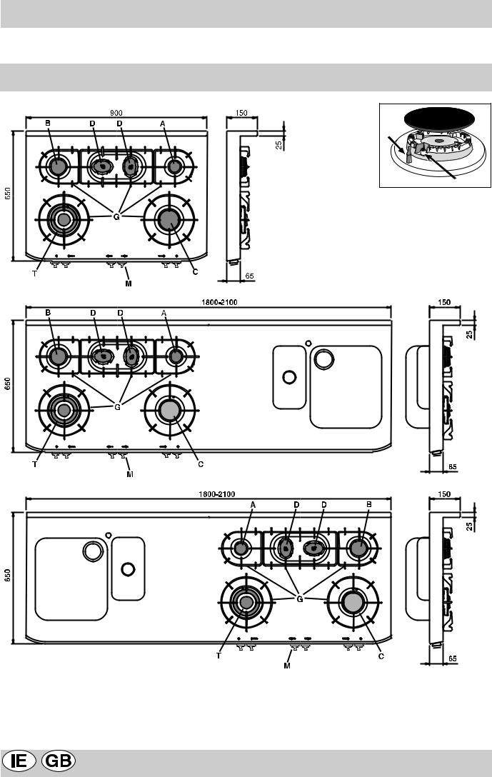
Visto da vicino
mod. XP 90 G mod. XP 90 GH
F |
E |
mod. XM 180 GS mod. XM 210 GS
mod. XM 180 GD mod. XM 210 GD
ABruciatore gas Ausiliario
BBruciatore gas Semirapido
CBruciatore gas Rapido
DBruciatore gas Semi-pesciera
TBruciatore gas Tripla corona
GGriglie di appoggio per recipienti di cottura
MManopole di comando dei bruciatori gas
ECandela di accensione dei bruciatori gas
FDispositivo di sicurezza - Interviene in caso di spegnimento accidentale della fiamma (trabocco di liquidi, correnti d'aria, ...) bloccando l'erogazione del gas al bruciatore.
2 |
IT |
|
|

Come utilizzarlo
Bruciatori gas
Sul pannello comandi, intorno ad ogni manopola "M" oppure sulle manopole stesse, sono indicati i simboli: Rubinetto chiuso 
Apertura massima 
Apertura minima
Inoltre, nelle vicinanze delle manopole i simboli 
 indicano la posizione sul piano del bruciatore relativo.
I bruciatori sono dotati di sicurezza contro fughe di gas a termocoppia. Questo dispositivo provvede a bloccare l’uscita del gas nel caso che la fiamma del bruciatore si spenga durante il funzionamento.
Per accendere uno dei bruciatori procedere come segue:
•ruotare la manopola corrispondente in senso antiorario fino al simbolo della fiamma grande;
•premere la manopola a fondo per azionare l’accensione automatica del gas  ;
;
•mantenere la manopola premuta per circa 10 secondi con la fiamma accesa per consentire il riscaldamento della termocoppia di sicurezza;
•rilasciare la manopola, verificando che l’accensione sia
avvenuta in modo stabile. In caso contrario, ripetere l’operazione.
Per avere la potenza minima ruotare la manopola verso il simbolo della fiamma piccola. Sono possibili regolazioni intermedie, posizionando la manopola tra il simbolo di fiamma grande e quello della fiamma piccola.
Per spegnere il bruciatore ruotare la manopola in senso orario fino alla posizione di chiuso " " .
" .
Importante:
•Non azionare il dispositivo di accensione automatica per più di 15 secondi consecutivi.
•In alcuni casi la difficoltà di accensione è dovuta ad eventuale aria che può trovarsi all’interno del condotto del gas.
•Nel caso di uno spegnimento accidentale della fiamma dei bruciatori, il gas continua ad uscire per qualche istante prima che intervenga il dispositivo di sicurezza. Chiudere la manopola di comando e non ritentare l’accensione per almeno 1 minuto, lasciando così dileguare il gas uscito che può essere pericoloso.
•Quando l’apparecchiatura non è in funzione controllare
che le manopole siano in posizione di chiuso " ". Si consiglia inoltre di chiudere il rubinetto principale del condotto di alimentazione del gas.
Consigli d'uso
Consigli pratici per l’uso dei bruciatori
Per ottenere dai bruciatori il massimo rendimento si consiglia adoperare solo pentole di diametro adatto al bruciatore utilizzato, evitando che la fiamma fuoriesca dal fondo della pentola (vedi tabella seguente).
Inoltre, quando un liquido inizia a bollire, si consiglia di ridurre la fiamma quanto basta per mantenere l’ebollizione.
Bruciatore |
ø Diametro Recipienti (cm) |
|
|
Rapido (C) |
22 – 24 |
|
|
Semi Rapido (B) |
16 – 20 |
|
|
Ausiliario (A) |
10 – 14 |
|
|
Semi-Pesciera (D) |
16 - 20 |
|
|
Tripla Corona (T) |
24 - 26 |
|
|
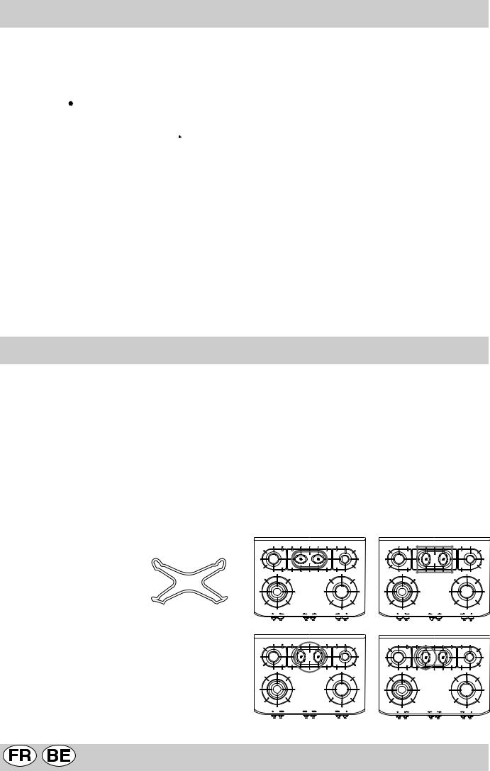
Il piano di cottura è dotato di una griglia di riduzione (fig.1), la quale va usata solo sul bruciatore ausiliario "A".
•Assicurarsi che i bruciatori risultino posizionati correttamente.
In particolare, i due bruciatori centrali, possono essere utilizzati insieme o separatamente con pentole di diverse forme e dimensioni come segue:
•Bruciatore doppio come “Pesciera” per recipienti ovali (Fig. A).
•Bruciatore doppio per bistecchiere o recipienti rettangolari o quadrati di dimensioni minime 28x28 cm (Fig. B)
•Bruciatore doppio per recipienti di grandi dimensioni (diametro 26-28 cm) (Fig. C).
•Bruciatore singolo per recipienti di media dimensione (diametro 16-20 cm) (Fig. D).
fig.1
Bruciatori “Semi-Pesciera”
L’utilizzo dei due bruciatori centrali “Semi-Pesciera” di forma elittica, ruotabili di 90°, dà al piano una maggiore flessibilità di impiego. Per ruotare di 90° i bruciatori "SemiPesciera" è necessario procedere come segue:
•Assicurarsi che i bruciatori siano freddi.
•Sollevare completamente il bruciatore dalla sua sede.
•Rimetterlo nella sua sede nella posizione desiderata.
fig.A
fig.C
fig.B
fig.D
IT |
3 |
|
|
C'è qualche problema?
Può accadere che il piano non funzioni o non funzioni bene. Prima di chiamare l'assistenza, vediamo che cosa si può fare.
Innanzi tutto verificare che non ci siano interruzioni nelle reti di alimentazione gas ed elettrica, ed in particolare i rubinetti gas a monte del piano siano aperti.
Il bruciatore non si accende o la fiamma non è uniforme
Avete controllato se:
•Sono ostruiti i fori di uscita del gas del bruciatore.
•Sono montate correttamente tutte le parti mobili che compongono il bruciatore.
•Ci sono correnti d'aria nelle vicinanze del piano.
La fiamma non rimane accesa nei modelli con sicurezza
Avete controllato se:
•Non avete premuto a fondo la manopola.
•Non avete mantenuto premuta a fondo la manopola per un tempo sufficiente ad attivare il dispositivo di sicurezza.
•Sono ostruiti i fori di fuoriuscita del gas in corrispondenza del dispositivo di sicurezza.
Il bruciatore in posizione di minimo non rimane acceso
Avete controllato se:
•Sono ostruiti i fori di fuoriuscita del gas.
•Ci sono correnti d'aria nelle vicinanze del piano.
•La regolazione del minimo non è corretta (Vedi paragrafo "Regolazione minimi").
I recipienti sono instabili
Avete controllato se:
•Il fondo del recipiente è perfettamente piano.
•Il recipiente è centrato sul bruciatore o sulla piastra elettrica.
Se, nonostante tutti i controlli, il piano non funziona e l'inconveniente da voi rilevato persiste, chiamate il Centro Assistenza Tecnica Merloni Elettrodomestici più vicino, comunicando queste informazioni:
-Il tipo di guasto.
-La sigla del modello (Mod. ...) riportata sul certificato di garanzia.
Non ricorrete mai a tecnici non autorizzati e rifiutate sempre l'installazione di pezzi di ricambio non originali.
La sicurezza una buona abitudine
•L'apparecchio è concepito per uso non professionale nelle abitazioni e le sue caratteristiche non vanno modificate.
•Le istruzioni sono valide solo per i paesi di destinazione i cui simboli figurano sul libretto e sulla targa matricola.
•La sicurezza elettrica di questo apparecchio è assicurata soltanto quando lo stesso è correttamente collegato ad un efficiente impianto di messa a terra come previsto dalle vigenti norme di sicurezza.
Trattandosi di fonti di pericolo, evitare che bambini e incapaci abbiano contatti con:
-i comandi e l'apparecchio in genere;
-gli imballaggi (sacchetti, polistirolo, chiodi ecc.);
-l'apparecchio, durante e subito dopo il funzionamento, visto il surriscaldamento;
-l'apparecchio inutilizzato (in questo caso vanno rese innocue le parti che potrebbero essere pericolose).
Vanno evitate le seguenti operazioni:
-toccare l'apparecchio con parti del corpo umide;
-l'uso quando si è a piedi nudi;
-tirare l'apparecchio o il cavo di alimentazione per staccarli dalla presa di corrente;
-operazioni improprie e pericolose;
-ostruire le aperture di ventilazione o smaltimento calore;
-che il cavo di alimentazione di piccoli elettrodomestici finisca su parti calde dell'apparecchio;
-l'esposizione ad agenti atmosferici (pioggia, sole);
-l'utilizzo di liquidi infiammabili nei pressi;
-l'impiego di adattatori, prese multiple e/o prolunghe;
-l'impiego di pentole instabili o deformate;
-chiudere il coperchio in vetro (se presente) con i bruciatori gas o le piastre elettriche ancore caldi;
-tentativi di installazione o riparazione senza l'intervento di personale qualificato.
Occorre assolutamente rivolgersi a personale qualificato nei seguenti casi:
-installazione (secondo le istruzioni del costruttore);
-quando si hanno dubbi sul funzionamento;
-sostituzione della presa in caso di incompatibilità con la spina dell'apparecchio.
Occorre rivolgersi a centri di assistenza autorizzati dal costruttore nei seguenti casi:
-in caso di dubbio sull'integrità dell'apparecchio dopo aver tolto l'imballaggio;
-danneggiamento o sostituzione del cavo di alimentazione;
-in caso di guasto o cattivo funzionamento, richiedendo i ricambi originali;
È opportuno effettuare le seguenti operazioni:
-solo la cottura dei cibi evitando altre operazioni;
-verificare l'integrità dopo aver tolto l'imballaggio;
-disconnettere l'apparecchio dalla rete di alimentazione elettrica in caso di cattivo funzionamento e prima di qualsiasi operazione di pulizia o manutenzione;
-quando inutilizzato, disinserire l'apparecchio dalla rete elettrica e chiudere il rubinetto del gas (se previsto);
-controllare sempre che le manopole siano nella posi-
zione “l”/” o” quando l'apparecchio non è utilizzato;
-tagliare il cavo di alimentazione dopo averlo disconnesso dalla rete elettrica quando si decide di non utilizzare più l'apparecchio.
Il costruttore non può essere considerato responsabile per eventuali danni derivanti da: errata installazione, usi impropri, erronei ed irragionevoli.
4 |
IT |
|
|
Come tenerlo in forma
Per una lunga durata dell’apparecchiatura è indispensabile eseguire frequentemente una accurata pulizia generale, tenendo conto che:
•L’apparecchiatura deve essere disinserita elettricamente prima di iniziare la pulizia.
•Le parti smaltate, cromate ed in vetro, vanno lavate con acqua tiepida senza usare polveri abrasive e sostanze corrosive che potrebbero rovinarle.
•Le parti in acciaio non devono essere pulite con diluenti o detersivi abrasivi; utilizzare preferibilmente solo un panno inumidito con acqua tiepida e detersivo liquido per piatti.
•Evitare di effettuare pulizie sulle parti ancora calde dell’apparecchiatura.
•Evitare di lasciare sulle parti smaltate o verniciate dei
liquidi acidi (aceto, succo di limone, detergenti aggressivi, ecc.)
•Gli elementi mobili dei bruciatori del piano di cottura vanno lavati frequentemente con acqua calda e detersivo avendo cura di eliminare le eventuali incrostazioni. Controllare che le fessure di uscita del gas non siano otturate. Asciugarli accuratamente prima di riutilizzarli.
•Eseguire frequentemente la pulizia della parte terminale delle candelette di accensione automatica del piano di cottura.
•Con il tempo può verificarsi il caso di un rubinetto che si blocchi o presenti difficoltà nella rotazione, pertanto sarà necessario provvedere alla pulizia interna e alla sostituzione del grasso. Questa operazione deve essere effettuata da un tecnico autorizzato dal costruttore.
Istruzioni per l'installatore
Le istruzioni che seguono sono rivolte all’installatore qualificato affinché compia le operazioni di installazione, regolazione e manutenzione tecnica nel modo più corretto e secondo le norme in vigore.
Importante: qualsiasi intervento di regolazione, manutenzione, ecc. deve essere eseguito con il piano elettricamente disinserito. Qualora sia necessario mantenerlo collegato elettricamente, si dovranno prendere le massime precauzioni.
Posizionamento
Questa apparecchiatura può essere installata e funzionare solo in locali permanentemente ventilati secondo le prescrizioni delle Norme UNI-CIG 7129 e 7131 in vigore. Devono essere osservati i seguenti requisiti:
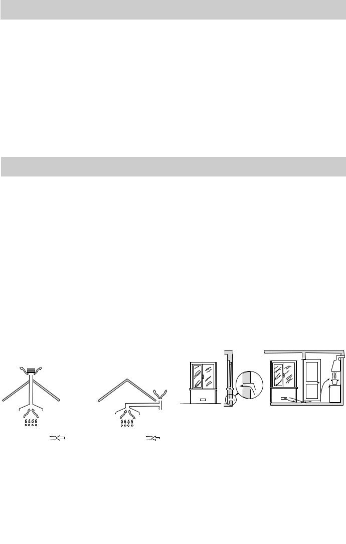
L’apparecchio deve scaricare i prodotti della combustione in una apposita cappa, che deve essere collegata ad un camino, canna fumaria o direttamente all’esterno (fig.2).
Se non è possibile l’applicazione di una cappa, è permesso l’uso di un elettroventilatore, installato su finestra o su parete affacciate all’esterno, da mettere in funzione contemporaneamente all’apparecchio.
fig.2
dell’aria deve avvenire attraverso aperture permanenti praticate su pareti del locale che danno verso l’esterno, oppure da condotti di ventilazione singoli o collettivi ramificati conformi alla norma UNI-CIG 7129. L’aria deve essere prelevata direttamente dall’esterno, lontana da fonti di inquinamento.
L’apertura di aerazione dovrà avere le seguenti caratteristiche (fig.3A):
•avere una sezione libera totale netta di passaggio di almeno 6 cm² per ogni kW di portata termica nominale dell’apparecchio, con un minimo di 100 cm² (la portata termica è rilevabile nella targhetta segnaletica);
•essere realizzata in modo che le bocche di apertura, sia all’interno che all’esterno della parete, non possano venire ostruite;
•essere protette ad esempio con griglie, reti metalliche, ecc. in modo da non ridurre la sezione utile suindicata;
•essere situate ad una altezza prossima al livello del pavimento.
|
|
Particolare A |
|
|
|
|
Locale |
Locale da |
|||||||
|
|
|
|
|
|
|
|
|
|
|
|
adiacente |
ventilare |
||
|
|
|
|
|
|
|
|
|
|
|
|
|
|
|
|
|
|
|
|
|
|
|
|
|
|
|
|
|
|
|
|
|
|
|
|
|
|
|
|
|
|
|
|
|
|
|
|
|
|
|
|
|
|
|
|
|
|
|
|
|
|
|
|
|
|
|
|
|
|
|
|
|
|
|
|
|
|
|
|
|
|
|
|
|
|
|
|
|
|
|
|
|
|
|
|
|
|
|
|
|
|
|
|
|
|
|
|
|
|
|
|
|
|
|
|
|
|
|
|
|
|
|
|
|
|
|
|
|
|
|
|
|
|
|
|
|
|
|
|
|
|
|
|
|
|
|
|
|
|
|
|
|
|
|
|
|
|
|
|
|
|
|
|
|
|
|
|
|
|
|
|
|
|
|
|
|
|
|
|
|
|
|
|
|
|
|
|
|
|
|
|
|
|
|
|
|
|
|
|
|
|
|
|
|
|
|
|
|
|
|
|
|
|
|
|
|
|
|
|
|
|
|
|
|
|
|
|
|
|
|
|
|
|
|
|
|
|
|
|
|
|
|
|
|
|
|
|
|
|
|
|
|
|
|
|
|
|
|
|
|
|
|
|
|
|
|
|
|
|
|
|
|
|
|
|
|
|
|
|
|
|
|
|
|
|
|
|
|
|
|
|
|
|
|
|
|
|
|
|
|
|
|
|
|
|
|
|
|
|
|
|
|
|
|
|
|
In camino o in canna fumaria ramificata |
Direttamente all’esterno |
|||||||||||||||
(riservata agli apparecchi di cottura)
Ventilazione ambiente cucina
É necessario che nell’ambiente dove viene installato l’apparecchio possa affluire una quantità di aria pari a quanta ne viene richiesta dalla regolare combustione del gas e dalla ventilazione dell’ambiente. L’afflusso naturale
A |
|
Esempi di aperture di ventilazione |
Maggiorazione della fessura fra |
per l’aria comburente |
porta e pavimento |
Fig. 3A |
Fig. 3B |
L’afflusso dell’aria può essere ottenuto anche da un locale adiacente purché questo locale non sia una camera da letto o un ambiente con pericolo di incendio quali rimesse, garage, magazzini di materiale combustibile, ecc., e che sia ventilato in conformità alla norma UNI-CIG 7129.
Il flusso dell’aria dal locale adiacente a quello da ventilare deve avvenire liberamente attraverso aperture permanenti, di sezione non minore di quella suindicata. Tali aperture potranno anche essere ricavate maggiorando la fessura tra porta e pavimento (fig.3B).
IT |
5 |
|
|
Se per l’evacuazione dei prodotti della combustione viene usato un elettroventilatore, l’apertura di ventilazione dovrà essere aumentata in funzione della massima portata d’aria dello stesso. L’elettroventilatore dovrà avere una portata sufficiente a garantire un ricambio orario di aria pari a 3÷5 volte il volume del locale.
Un utilizzo intensivo e prolungato dell’apparecchio può necessitare di un’aerazione supplementare, per esempio l’apertura di una finestra o un’aerazione più efficace aumentando la potenza di aspirazione dell’elettroventilatore se esso esiste.
I gas di petrolio liquefatti, più pesanti dell’aria, ristagnano verso il basso. Quindi i locali contenenti bombole di GPL devono avere delle aperture verso l’esterno al livello del pavimento, così da permettere l’evacuazione dal basso delle eventuali fughe di gas. Inoltre non depositare bombole di GPL (anche vuote) in locali a livello più basso del suolo; è opportuno tenere nel locale solo la bombola in utilizzo, collegata lontana da sorgenti di calore che possano portarla ad una temperatura superiore a 50 °C.
Installazione
Queste istruzioni riguardano un apparecchio di classe 1 e categoria II 2H3+.
È necessario prendere le opportune precauzioni al fine di assicurare una installazione rispondente alle norme antinfortunistiche in vigore (CEI-UNI-CIG) per l’allacciamento elettrico e gas.
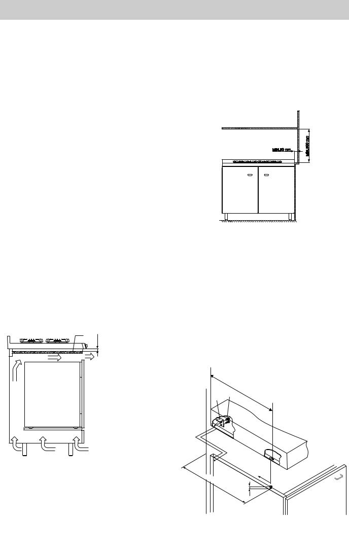
Nel caso di installazione sopra un forno da incasso devono essere previste delle opportune prese d’aria come in fig.4• (entrata dal basso di almeno 200 cm², uscita dalla parte superiore di almeno 180 cm²) per consentire una adeguata aerazione all’interno del mobile.
Sia il cavo alimentazione elettrico che il tubo del gas devono essere posizionati in modo da evitare il contatto con parti
A
15mm
180cm²
fig.4
calde dell’involucro del forno, onde evitare surriscaldamenti.
Nel caso di installazione sopra un forno da incasso senza ventilazione forzata di raffreddamento, sotto il piano deve essere installato un pannello di legno “A” (fig.4) come isolamento, posizionato ad una distanza minima di 15 mm dall’involucro del piano.
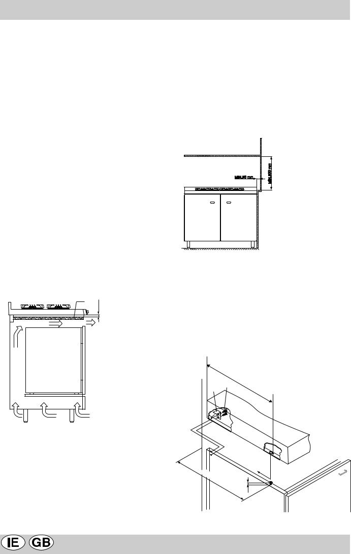
Per il buon funzionamento dell'apparecchio installato nei mobili devono essere rispettate le distanze minime indicate in fig.5.
fig.5
Il piano è predisposto con grado di protezione contro i riscaldamenti eccessivi di tipo Y secondo la norma EN60335-2-6. Le superfici adiacenti del mobile e la parete posteriore devono essere di materiale idoneo per resistere ad una temperatura di 65 °C.
Per fissare al piano al mobile eseguire le seguenti operazioni (fig.6);
•avvitare al mobile 2 viti “A” (in dotazione) con le distanze dalla parete posteriore indicate in figura, lasciando le teste delle viti sporgenti 1.5 mm dal legno;
•agganciare il piano alle 2 viti “A” e spingerlo all'indietro;
•fissarlo al mobile nella parte posteriore usando le 2 squadrette “B” e le 4 viti “C” in dotazione.
fig.6
|
C |
X |
mm |
B |
|
||
|
|
|
muro
X |
|
mm |
mm |
|
1.5 |
A |
6 |
IT |
|
|
Collegamento alimentazione gas
•Il collegamento dell’apparecchio alla tubazione o alla bombola del gas deve essere effettuato secondo le prescrizioni delle norme in vigore (UNI-CIG 7129 e 7131) solo dopo essersi accertati che l’apparecchiatura è regolata per il tipo di gas con cui sarà alimentata.
•Questo apparecchio è predisposto per funzionare con il gas indicato nell’etichetta posta sul piano stesso. Nel caso che il gas distribuito non corrisponda a quello per cui l’apparecchio è predisposto, procedere alla sostituzione degli iniettori corrispondenti (in dotazione), consultando il paragrafo “Adattamento ai diversi tipi di gas”.
•Per un sicuro funzionamento, per un adeguato uso dell’energia e maggiore durata dell’apparecchiatura, assicurarsi che la pressione di alimentazione rispetti i
valori indicati nella tabella 1 “Caratteristiche dei bruciatori ed ugelli”, altrimenti installare sulla tubazione di ingresso un apposito regolatore di pressione secondo la norma UNI-CIG 7430.
•Effettuare Il collegamento in modo da non provocare sollecitazioni di nessun genere sull’apparecchio.
Collegare al raccordo orientabile (filettato ½"G maschio), posto nel lato posteriore destro dell’apparecchio (fig.7), per mezzo di tubo metallico rigido e a raccordi conformi alla norma UNI-CIG 7129, oppure con tubo flessibile metallico a parete continua conforme alla norma UNI-CIG 9891, la cui massima estensione non deve superare i 2000 mm.
Nel caso sia necessario ruotare il raccordo, sostituire tassativamente la guarnizione di tenuta (in dotazione con l’apparecchio).
fig.7
Ad installazione ultimata accertarsi che la tenuta del circuito gas, delle connessioni interne e dei rubinetti sia perfetta impiegando una soluzione saponosa (mai una fiamma).
Verificare inoltre che il tubo di collegamento non possa venire a contatto con parti mobili in grado di danneggiarlo o schiacciarlo.
Accertarsi che la conduttura del gas naturale sia sufficiente per alimentare l’apparecchio quando tutti i bruciatori sono in funzione.
Importante: Per effettuare l’allacciamento con gas liquido (in bombola), interporre un regolatore di pressione conforme alla norma UNI-CIG 7432-75.
Adattamento ai diversi tipi di gas
Per adattare il piano ad un tipo di gas diverso da quello per il quale esso è predisposto (indicato sulla etichetta fissata nella parte superiore del piano o sull'imballo), occorre sostituire gli ugelli dei bruciatori effettuando le seguenti operazioni:
•togliere le griglie del piano e sfilare i bruciatori dalle loro sedi.
A
fig.8
•svitare gli ugelli (fig.8), servendosi di una chiave a tubo da 7 mm. e sostituirli con quelli adatti al nuovo tipo di gas (vedi tabella 1 “Caratteristiche dei bruciatori ed ugelli”).
•rimontare le parti eseguendo all’inverso le operazioni.
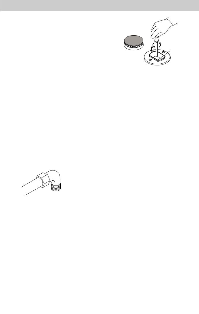
Regolazione minimi
•portare il rubinetto sulla posizione di minimo;
•togliere la manopola ed agire sulla vite di regolazione (figura 9) posta di fianco all’astina del rubinetto fino ad ottenere una piccola fiamma regolare cacciavite (svitando la vite il minimo aumenta, avvitandola diminuisce).
N.B.: nel caso dei gas liquidi, la vite di regolazione dovrà essere avvitata a fondo.
•verificare che ruotando rapidamente la manopola dalla posizione di massimo a quella di minimo non si abbiano spegnimenti dei bruciatori.
fig.9
Collegamento elettrico
È OBBLIGATORIO IL COLLEGAMENTO A TERRA DELL’APPARECCHIATURA.
I piani sono predisposti per il funzionamento con corrente alternata alla tensione e frequenza di alimentazione indicate sulla targhetta caratteristiche (posta sotto il piano o alla fine del libretto istruzioni). Accertarsi che il valore locale della tensione di alimentazione sia lo stesso di quello indicato sulla targhetta.
Allacciamento del cavo alimentazione elettrico alla rete
Per i modelli privi di spina, montare sul cavo una spina normalizzata per il carico indicato sulla targhetta caratteristiche e collegarla ad una adeguata presa di corrente.
IT |
7 |
|
|
Desiderando un collegamento diretto alla rete è necessario interporre tra l’apparecchio e la rete un interruttore onnipolare con apertura minima tra i contatti di 3 mm., dimensionato al carico e rispondente alle norme in vigore. Il filo di terra giallo-verde non deve essere interrotto dall’interruttore.
Il cavo di alimentazione deve essere posizionato in modo che non raggiunga in nessun punto una temperatura superiore di 50 °C a quella ambiente.
Nel caso di installazione sopra un forno da incasso l’allacciamento elettrico del piano e quello del forno devono essere realizzati separatamente, sia per ragioni di sicurezza elettrica, sia per facilitare l’eventuale estraibilità del forno.
Non utilizzare riduzioni, adattatori o derivatori in quanto essi potrebbero provocare riscaldamenti o bruciature. Prima di effettuare l’allacciamento accertarsi che:
•la valvola limitatrice e l’impianto domestico possano sopportare il carico dell’apparecchiatura (vedi targhetta caratteristiche);
•l’impianto di alimentazione sia munito di efficace collegamento a terra secondo le norme e le disposizioni di legge in vigore;
•la presa o l’interruttore onnipolare siano facilmente raggiungibili con il piano installato.
DECLINIAMO OGNI RESPONSABILITÀ NEL CASO LE NORME ANTINFORTUNISTICHE NON VENGANO RISPETTATE.
Sostituzione del cavo
Utilizzare un cavo in gomma del tipo H05RR-F con una sezione 3 x 0.75 mm².
Il conduttore giallo-verde dovrà essere più lungo di 2÷3 cm. degli altri conduttori.
Caratteristiche dei bruciatori ed ugelli
Tabella 1 |
|
|
|
|
|
Gas liquido |
|
|
Gas naturale |
||
|
|
|
|
|
|
|
|
|
|
||
Bruciatore |
Diametro |
Potenza |
By-pass |
Ugello |
Portata * |
Ugello |
Portata * |
||||
|
(mm) |
termica |
1/100 |
1/100 |
|
g/h |
1/100 |
l/h |
|||
|
|
kW (H.s.*) |
|
|
|
|
|
|
|
||
|
|
Nomin. |
|
Ridot. |
(mm) |
(mm) |
G30 |
|
G31 |
(mm) |
G20 |
|
|
|
|
||||||||
|
|
|
|
|
|
|
|
|
|
|
|
Rapido C |
100 |
3.00 |
|
0.7 |
40 |
86 |
218 |
|
214 |
116 |
286 |
|
|
|
|
|
|
|
|
|
|
|
|
Semirapido B |
75 |
1.65 |
|
0.4 |
30 |
64 |
120 |
|
118 |
96 |
157 |
|
|
|
|
|
|
|
|
|
|
|
|
Ausiliario A |
55 |
1.00 |
|
0.3 |
27 |
50 |
73 |
|
71 |
71 |
95 |
|
|
|
|
|
|
|
|
|
|
|
|
Tripla corona T |
130 |
3.25 |
|
1.3 |
57 |
91 |
236 |
|
232 |
124 |
309 |
|
|
|
|
|
|
|
|
|
|
|
|
Semi-pesciera D |
- |
1.50 |
|
0.4 |
28 |
60 |
109 |
|
107 |
95 |
143 |
|
|
|
|
|
|
|
|
|
|
|
|
Pressioni di |
|
Nominale (mbar) |
|
30 |
|
37 |
|
20 |
|||
|
Minima (mbar) |
|
20 |
|
25 |
|
17 |
||||
alimentazione |
|
|
|
|
|||||||
|
Massima (mbar) |
|
35 |
|
45 |
|
25 |
||||
|
|
|
|
|
|||||||
|
|
|
|
|
|
|
|
|
|
|
|
*A 15°C e 1013 mbar-gas secco Propano G31 H.s. = 50,37 MJ/kg Butano G30 H.s. = 49,47 MJ/kg Naturale G20 H.s. = 37,78 MJ/m3
Questa apparecchiatura è conforme alle seguenti Direttive Comunitarie:
-73/23/CEE del 19/02/73 (Bassa Tensione) e successive modificazioni;
-89/336/CEE del 03/05/89 (Compatibilità Elettromagnetica) e successive modificazioni;
-90/396/CEE del 29/06/90 (Gas) e successive modificazioni;
-93/68/CEE del 22/07/93 e successive modificazioni.
8 |
IT |
|
|
Congratulations on choosing an Ariston appliance, which you will find is dependable and easy to use. We recommend that you read this manual for best performance and to extend the life of your appliance. Thank you.
Close-up view
F |
E |
mod. XP 90 G mod. XP 90 GH
model XM 180 GS model XM 210 GS
model XM 180 GD model XM 210 GD
AAuxiliary gas burner
BSemi-rapid gas burner
CRapid gas burner
DHalf fish-Kettle burner
TTriple ring gas burner
GPan supports
MControl knobs for gas burners
EIgnitor for gas burners
FSafety device - Activates if the flame accidentally goes out (spills, drafts, etc.), interrupting the delivery of gas to the burner.
9
How to use your appliance
Gas burners
The burners differ in size and power. Choose the most appropriate one for the diameter of the cookware being used.
The burner can be regulated with the corresponding control knob "M" by using one of the following settings: Off 
High flame 
Low flame 
The symbols 
 near the knobs show the position of the relative burner on the hob.
The burners are fitted with automatic ignition and thermocouple safety device, which automatically cuts off the gas from the burner in a few seconds if the flame accidentally goes out during operation.
To ignite a burner, proceed as follows:
•turn the relative knob counter-clockwise until the pointer is on the high-flame symbol;
•press the knob down fully to activate the automatic gas ignition  ;
;
•keep the knob pressed down for about 10 seconds with the flame lit to allow the safety thermocouple to be
heated;
•release the knob, checking that the flame is stable. If it is not, repeat the operation.
For minimum power, turn the knob towards the low flame symbol. Intermediate positions are possible by putting the knob anywhere between the high and the low flame symbol.
To turn off the burner, turn the knob clockwise to the off position " " .
" .
Important:
•Do not activate the automatic ignition device for more than 15 consecutive seconds.
•Difficulty in ignition is sometimes due to air inside the gas duct.
•If a burner flame accidentally goes out, the gas continues to exit for a few moments before the safety device activates. Turn the control knob to the off position and do not attempt ignition again for at least 1 minute, thereby letting the gas disperse, which could otherwise be a danger.
•When the equipment is not in operation, check that the
knobs are in the off position " " . The main gas supply cut-off cock should also be closed.
Practical advice
Using the burners
To obtain maximum efficiency from the burners, it is advisable to use only pans with a diameter that is suitable for the burner being used, so that the flame does not extend beyond the pan base (see following table).
When a liquid starts boiling, it is advisable to turn the flame down just enough to keep the liquid simmering.
Burner |
ø Cookware diameter (cm) |
|
|
Rapid (C) |
22 – 24 |
|
|
Semi-Rapid (B) |
16 – 20 |
|
|
Auxiliary (A) |
10 – 14 |
|
|
Semi-Fishburner (D) |
16 - 20 |
|
|
Triple Ring (T) |
24 - 26 |
|
|
The hob is fitted with a pan reducing support (fig.1), which should only be used on the auxiliary burner "A".
•Replace it in its housing in the position desired.
•Make sure that the burners are positioned correctly before use.
In addition, the two central burners can be used in tandem or speartely with cookware of different shapes and sizes:
•Double burner for a fish-kettle or oval cookware (Fig. A).
•Double burner for a griddle or rectangular/square cookware with minimum dimensions of 28x28 cm (Fig. B).
•Double burner for large cookware (diameter of 26-28 cm) (Fig. C).
•Single burner for medium size cookware (diameter of 16-20 cm) (Fig. D).
fig.1
Using the Half Fish-Kettle Burner
The two central burners, or Half Fish-Kettle burners, are eliptic in form and can be turned up to 90°. This makes the cooktop more flexible in terms of how it can be used.
To turn the two central burners 90°, proceed as follows:
•Make sure that the burners are cool;
•Lift the burner completely out of its housing.
fig.A |
fig.B |
fig.C |
fig.D |
10
Is there a problem?
It may occur that the cooktop does not function or does not function properly. Before calling customer service for assistance, lets see what can be done.
First of all, check to see that there are no interruptions in the gas and electrical supplies, and, in particular, that the gas valves for the mains are open.
The burner does not light or the flame is not uniform around the burner.
Check to make sure that:
•The gas holes on the burner are not clogged;
•All of the movable parts that make up the burner are mounted correctly;
•There are no draughts around the cooking surface.
The flame does not stay lighted on the model with the safety device.
Check to make sure that:
•You press the knob all the way in;
•You keep the knob pressed in long enough to activate the safety device.
•The gas holes are not clogged in the area corresponding to the safety device.
The burner does not remain on when set to "Low".
Check to make sure that:
•The gas holes are not clogged.
•There are no draughts near the cooking surface.
•The minimum has been adjusted correctly (see the section entitled, "Minimum Regulation").
The cookware is not stable.
Check to make sure that:
•The bottom of the cookware is perfectly flat.
•The cookware is centered correctly on the burner or electric hot plate.
•The support grids have not been inverted.
If, despite all of these checks, the cooktop does not function properly and problem persists, call the nearest Merloni Elettrodomestici Customer Service Centre, informing them of:
-The type of problem.
-The abbreviation used to identify the model (Mod. ...) as indicated on the warranty.
Never call upon technicians not authorized by the manufacturer, and refuse to accept spare parts that are not original.
Safety Is a Good Habit to Get Into
•This appliance is designed for non-professional use in the home and its features and technical characteristics must not be modified.
•These instructions are only valid for the countries the symbols for which appear on the manual and the serial plate.
•The electrical system of this appliance is safe only when it is correctly connected to an adequate earthing system, as required by current safety standards.
Prevent children and the disabled from coming into contact or having access to the following, as they are possible sources of danger:
-The controls and the appliance in general;
-The packaging (plastic bags, polystyrene, nails, etc.);
-The appliance, during and immediately after use given the heat generated by its use;
-The appliance when no longer in installed (in this case, all potentially dangerous parts must be made safe).
The following should be avoided:
-Touching the appliance with wet parts of the body;
-Using the appliance with bare feet;
-Pulling on the appliance or the power supply cable to disconnect them from the electrical outlet;
-Improper and/or dangerous use;
-Obstructing the ventilation or heat dissipation slots;
-Allowing the power supply cable of small appliances to come into contact with the hot parts of the cooktop;
-Exposure to atmospheric agents (rain, sun);
-Using flammable liquids nearby;
-Using adaptors, multiple outlet plugs and/or extensions;
-Using unstable or deformed cookware;
-Trying to install or repair the appliance without the assistance of qualified personnel.
The assistance of qualified personnel must be called upon in the following cases:
-Installation (in accordance with the manufacturer's instructions);
-When in doubt about the operation of the appliance;
-Replacement of the electrical outlet becuase it is incompatible with the plug.
Contact service centers authorized by the manufacturer in the following cases:
When in doubt about the condition of the appliance after having removed the packing;
-Damage to or replacement of the power supply cable;
-In the case of a breakdown or malfunction: ask for original spare parts.
It is recommended that you follow the guidelines below:
-Only use the appliance to cook food, avoiding all other uses;
-Check the condition of the appliance after it has been unpacked;
-Disconnect the appliance from the power supply in the event of malfunction and always before cleaning or maintenance;
-When not in use, disconnect the appliance from the power supply and turn off the gas valve (if present);
-Always check to make sure that the control knobs are on the “•”/”o” setting when the appliance is not in use;
-Cut the power supply cable after disconnecting it from the electrical mains when you decide to no longer use the appliance.
•The manufacturer will not be held liable for any damages arising out of: incorrect installation or improper, incorrect or unreasonable use.
11

How to Keep Your Cooktop in Shape
To ensure long life of the appliance, it is essential to carry out a thorough general clean frequently, taking into account that:
•The appliance should be disconnected from the mains supply before starting cleaning operations.
•Avoid cleaning appliance parts when they are still warm.
•The enamelled or chromed or glass parts must be washed with warm water without using abrasive powders or corrosive substances which could ruin them.
•The steel parts and especially the areas with the screenprinted symbols should not be cleaned with diluents or abrasive detergents. It is advisable to use only a damp cloth with tepid water and a liquid detergent. After cleaning, the surfaces should be rinsed thoroughly with water and then dried well.
•Avoid leaving acid liquids (vinegar, lemon juice,
aggressive detergents, etc.) on enamelled or painted parts.
•The removable parts of the burners should be washed frequently with warm water and soap, making sure to remove caked-on substance. Check that the gas outlet slits are not clogged. Dry the burners carefully before using them again.
•Frequently clean the end part of the automatic glow plugs of the hob.
Greasing the taps
As time passes, a tap may lock or become difficult to turn. In this case it will be necessary to clean inside and replace the grease.
Important: This procedure must be performed by a technician authorized by the manufacturer.
Instructions for the installer
The following instructions are provided for qualified installers so that they may accomplish installation, adjustment and technical maintenance operations correctly and in compliance with current regulations and standards.
Important: the hob should be disconnected from the mains electricity supply before any adjustment, maintenance, etc. is carried out. Maximum caution should be used whenever it is necessary to keep the appliance connected to the electricity supply.
Positioning
This appliance may only be installed and operated in permanently ventilated rooms in compliance with provisions laid down by current regulations and standards. The following requirements must be observed:
•The appliance must discharge combustion products into a special hood, which must be connected to a chimney, flue pipe or directly to the outside (fig.2).
•If it is impossible to fit a hood, the use of an electric fan is permitted, either installed on a window or on an external wall, which must be switched on at the same time as the appliance.
fig.2
combustion of the gas and for ventilating the same room. Air must be taken in naturally through permanent apertures made in the outside walls of the room or through single or branching collective ventilation ducts in compliance with the standards in force. The air must be taken directly from the outside, from an area far from sources of pollution. The ventilation aperture must have the following characteristics (fig.3A):
·total free cross section of passage of at least 6 cm² for every kW of rated heating capacity of the appliance, with a minimum of 100 cm² (the heating capacity is indicated on the rating plate);
·it must be made in such a way that the aperture, both on the inside and outside of the wall, cannot be obstructed;
·it must be protected, e.g. with grills, wire mesh, etc. in such a way that the above-mentioned free section is not reduced;
·it must be situated as near to floor level as possible.
|
|
Detail A |
|
|
|
|
|
|
Adjacent |
Room to be |
|||||
|
|
|
|
|
|
|
|
|
|
|
|
Room |
Vented |
||
|
|
|
|
|
|
|
|
|
|
|
|
|
|
|
|
|
|
|
|
|
|
|
|
|
|
|
|
|
|
|
|
|
|
|
|
|
|
|
|
|
|
|
|
|
|
|
|
|
|
|
|
|
|
|
|
|
|
|
|
|
|
|
|
|
|
|
|
|
|
|
|
|
|
|
|
|
|
|
|
|
|
|
|
|
|
|
|
|
|
|
|
|
|
|
|
|
|
|
|
|
|
|
|
|
|
|
|
|
|
|
|
|
|
|
|
|
|
|
|
|
|
|
|
|
|
|
|
|
|
|
|
|
|
|
|
|
|
|
|
|
|
|
|
|
|
|
|
|
|
|
|
|
|
|
|
|
|
|
|
|
|
|
|
|
|
|
|
|
|
|
|
|
|
|
|
|
|
|
|
|
|
|
|
|
|
|
|
|
|
|
|
|
|
|
|
|
|
|
|
|
|
|
|
|
|
|
|
|
|
|
|
|
|
|
|
|
|
|
|
|
|
|
|
|
|
|
|
|
|
|
|
|
|
|
|
|
|
|
|
|
|
|
|
|
|
|
|
|
|
|
|
|
|
|
|
|
|
|
|
|
|
|
|
|
|
|
|
|
|
|
|
|
|
|
|
|
|
|
|
|
|
|
|
|
|
|
|
|
|
|
|
|
|
|
|
|
|
|
|
|
|
|
|
|
|
|
|
|
|
|
|
|
|
|
|
|
|
|
|
In a chimney stack or branched flue. |
Directly to the Outside |
||||||||||||||
(exclusively for cooking appliances)
Kitchen ventilation
The air flow into the room where the appliance is installed must equal the quantity of air that is required for regular
A
|
|
|
|
|
|
|
|
|
|
|
|
|
|
|
|
Examples of ventilation holes |
Enlarging the ventilation slot |
||||||
for comburant air. |
between window and floor. |
||||||
|
|
Fig. 3A |
|
|
Fig. 3B |
||
The air inflow may also be obtained from an adjoining room, provided the latter is not a bedroom or a room where there is a risk of fire, such as garages, mews, fuel stores, etc. and is ventilated in compliance with the standards in force. Air from the adjoining room to the one to be ventilated may be made to freely pass through permanent apertures with a cross section at least equal to that indicated above. These apertures may also be obtained by increasing the gap between the door and the floor (fig.3B).
12
If an electric fan is used for extracting the combustion products, the ventilation aperture must be increased in relation to its maximum performance. The electric fan should have a sufficient capacity to guarantee an hourly exchange of air equal to 3-5 times the volume of the kitchen.
Prolonged, intensive use of the appliance may require extra ventilation, e.g. an open window or a more efficient ventilation system by increasing the extraction power of the electric fan if installed.
Liquid petroleum gas descends towards the floor as it is heavier than air. Apertures in the outside walls in rooms containing LPG cylinders should therefore be at floor level, in order to allow any gas from leaks to be expelled. Do not store LPG cylinders (even when empty) in basements/ rooms below ground level; it is advisable to keep only the cylinder in use in the room at any one time and connected far from heat sources which could raise its temperature to above 50 °C.
Installation
These instructions are given for a class 1 and category II 2H3+ appliance.
Suitable precautions must be taken to ensure that the installation is in compliance with current accidentprevention regulations regarding electrical and gas connections.
When installing above a built-under oven, suitable air vents
A
15mm
180cm²
fig.4
should be provided for as shown in fig.4 (inlet at least 200 cm² from the bottom, outlet at least 180 cm² from the top part) to allow adequate ventilation inside the housing unit. Both the electricity supply cable and the gas pipe must not touch hot parts of the oven housing, in order to avoid overheating.
When installing above a built-under oven without forced cooling ventilation, a wooden panel “A” (fig.4) should be installed beneath the hob as insulation, positioning it at a minimum distance of 15 mm from the hob housing.
For trouble-free operation of the appliance set into kitchen units, the minimum distances indicated in fig.5 should be complied with.
fig.5
The hob has a protection rating Y against overheating, in accordance with standard EN60335-2-6. The surfaces adjoining the unit and the wall to the rear should be in suitable material to withstand a temperature of 65°C.
To fix the hob to the unit, proceed as follows (fig.6);
•tighten 2 screws “A” (provided) into the unit, leaving the screw heads projecting 1.5 mm from the wood;
•hook the hob onto the 2 screws “A” and push backwards;
•fix the hob to the unit at the rear using the 2 corner brackets “B” and the 4 screws “C” provided.
fig.6
|
C |
X |
mm |
B |
|
||
|
|
|
wall
X |
|
mm |
mm |
|
1.5 |
A |
13

Gas supply connection
•Check that the appliance is set for the type of gas available and then connect it to the mains gas piping or the gas cylinder in compliance with current regulations and standards.
•This appliance is designed and set to work with the gas indicated on the label situated on the actual hob. If the gas supply is other than the type for which the appliance has been set, proceed with replacing the corresponding nozzles (provided), following instructions given in the paragraph “Adaptation to different types of gas”.
•For trouble-free operation, suitable use of energy and longer life of the appliance, make sure that the supply pressure complies with the values indicated in the table 1 "burners and nozzles specifications, otherwise install a special pressure regulator on the supply pipe in compliance with current standards and regulations.
•Connect in such a way that the appliance is subjected to no strain whatsoever.
Either a rigid metal pipe with fittings in compliance with the standards in force must be used for connecting to the nipple union (threaded ½"G male fitting) situated at the rear of the appliance to the right (fig.7), or flexible steel pipe in compliance with the standards in force, which must not exceed 2000 mm in length.
Should it be necessary to turn the fitting, the gasket (supplied with the appliance) must be replaced.
fig.7
Upon completion of installation, check the gas circuit, the internal connections and the taps for leaks using a soapy solution (never a flame).
Also check that the connecting pipe cannot come into contact with moving parts which could damage or crush it.
Make sure that the natural gas pipe is adequate for a sufficient supply to the appliance when all the burners are lit
Important: A pressure regulator, in compliance with the standards in force, must be inserted when connecting to a liquid gas supply (in a cylinder).
Adaptation to a different type of gas
If the hob is to be converted for use with a type of gas other than that for which it was set in the factory (indicated on the label to be found on the hob), the burner nozzles should be replaced as follows:
•Remove the pan supports and the burners.
•Unscrew the nozzles “A” (fig.8) using a 7 mm socket wrench and replace them with the ones which have a diameter suitable for the type of gas to be used, according to the table 1 "burners and nozzles specifications).
•Reassemble the parts following the instructions in reverse order.
A
fig.8
Adjusting the low flame
•Put the tap to the low flame position;
•Remove the tap knob and turn the adjusting screw, situated to the side of the tap stem (fig.9), using a screwdriver (loosening the screw increases the height of the flame, tightening decreases it).
note: the adjusting screw must be fully screwed down for liquid gas.
•Having obtained the low flame setting required and with the burner lit, abruptly change the position of the knob several times from minimum to maximum and vice versa and check that the flame does not go out.
fig.9
Electrical connection
THE APPLIANCE MUST BE EARTHED
The hob is designed to work with alternating current at the supply voltage and frequency indicated on the rating plate (situated under the hob or at the end of the instruction booklet). Make sure that the local supply voltage corresponds to the voltage indicated on the rating plate.
Connecting the supply cable to the mains electricity supply
For models supplied without a plug, fit a standard plug, suitable for the load indicated on the rating plate, onto the cable and connect to a suitable socket.
To connect directly to the mains supply, a double-pole switch with a contact separation of at least 3 mm suitable for the load and complying with current standards and regulations, must be fitted between the appliance and the mains supply outlet.
The yellow-green earth wire must not be interrupted by the switch.
The supply cable must be in such a position that no part of
14

it can reach a temperature of 50 °C above room temperature.
For installation above a built-under oven, the hob and the oven must be connected separately to the electricity supply both for safety reasons and for easy removal of the oven if necessary.
Do not use adapters or shunts as they could cause heating or burning.
Before connecting to the power supply, make sure that:
•the limiter valve and the domestic system can withstand the load from the appliance (see rating plate);
•the supply system is efficiently earthed according to standards and laws in force;
•the socket or double-pole switch are easily accessible when the appliance is installed.
Important: the wires in the mains lead are coloured in accordance with the following code:
Green & Yellow |
- Earth |
Blue |
- Neutral |
Brown |
- Live |
As the colours of the wires in the mains lead may not correspond with the coloured markings identifying the terminals in your plug, proceed as follows:
Connect the Green & Yellow wire to terminal marked “E” or  or coloured Green or Green & Yellow.
Connect the Brown wire to the terminal marked “L” or coloured Red.
Connect the Blue wire to the terminal marked “N” or coloured Black.
FAILURE TO OBSERVE THE ACCIDENT-PREVENTION REGULATIONS RELIEVES THE MANUFACTURER OF ALL LIABILITY.
Replacing the cable
Use a rubber cable of the type H05RR-F with a suitable cross section 3 x 0.75 mm².
The yellow-green earth wire must be 2-3 cm longer than the other wires.
Burners and nozzles specifications
Table 1 |
|
|
|
|
|
Liquid gas |
|
|
Natural gas |
||
|
|
|
|
|
|
|
|
|
|
||
Burner |
Diameter |
Thermal power |
By-pass |
Injector |
Flow * |
Injector |
Flow* |
||||
|
(mm) |
kW (H.s.*) |
1/100 |
1/100 |
|
g/h |
1/100 |
l/h |
|||
|
|
Nomin. |
|
Reduc. |
(mm) |
(mm) |
G30 |
|
G37 |
(mm) |
G20 |
|
|
|
|
||||||||
|
|
|
|
|
|
|
|
|
|
|
|
Rapid C |
100 |
3.00 |
|
0.7 |
40 |
86 |
218 |
|
214 |
116 |
286 |
|
|
|
|
|
|
|
|
|
|
|
|
Semi-rapid B |
75 |
1.65 |
|
0.4 |
30 |
64 |
120 |
|
118 |
96 |
157 |
|
|
|
|
|
|
|
|
|
|
|
|
Auxiliary A |
55 |
1.00 |
|
0.3 |
27 |
50 |
73 |
|
71 |
71 |
95 |
|
|
|
|
|
|
|
|
|
|
|
|
Triple ring T |
130 |
3.25 |
|
1.3 |
57 |
91 |
236 |
|
232 |
124 |
309 |
|
|
|
|
|
|
|
|
|
|
|
|
Semi-Fishburner D |
- |
1.50 |
|
0.4 |
28 |
60 |
109 |
|
107 |
95 |
143 |
|
|
|
|
|
|
|
|
|
|
|
|
Supply pressure |
|
|
|
|
|
|
30 |
|
37 |
|
20 |
|
|
|
|
|
|
|
|
|
|
|
|
*At 15°C and 1013 mbar-dry gas Propane G31 H.s. = 50,37 MJ/kg Butane G30 H.s. = 49,47 MJ/kg Methane G20 H.s. = 37,78 MJ/m3
This appliance conforms with the following European Economic Community directives:
-73/23/EEC of 19/02/73 (Low Voltage) and subsequent modifications;
-89/336/EEC of 03/05/89 (Electromagnetic Compatibility) and subsequent modifications;
-90/396/EEC of 29/06/90 (Gas) and subsequent modifications;
-93/68/EEC of 22/07/93 and subsequent modifications.
15

Merci d'avoir choisi un produit Ariston, fiable et facile à utiliser. Pour mieux le connaître et l'utiliser le plus longtemps possible, nous vous conseillons de lire attentivement ce livret. Merci.
Vu de près
mod. XP 90 G mod. XP 90 GH
F |
E |
model XM 180 GS model XM 210 GS
model XM 180 GD model XM 210 GD
ABrûleur gaz Auxiliaire
BBrûleur gaz Demi-rapide
CBrûleur gaz Rapide
T Brûleur gaz Triple couronne D Brûleur gaz Demi-Poissonière G Grilles support de casseroles
M Manettes de commande des brûleurs gaz
EBougie d'allumage des brûleurs gaz
FDispositif de sécurité -Intervient en cas d'extinction accidentelle de la flamme (débordement de liquides, courants d'air, ...) en interrompant automatiquement l'arrivée de gaz.
16
Comment l'utiliser
Brûleurs gaz
Ils ont des dimensions et des puissances différentes. Choisissez-en un en fonction du diamètre de la casserole utilisée. Pour le réglage du brûleur choisi, servez-vous de la manette correspondante "M", comme suit:
Robinet fermé
Ouverture maximale  Ouverture minimale
À côté des manettes figurent les symboles
 indiquant la position du brûleur correspondant sur le plan de cuisson. Le plan de cuisson est muni d'un dispositif de sécurité à thermocouple contre les fuites de gaz sur les brûleurs, celui-ci permet de couper automatiquement la sortie du gaz du brûleur en quelques secondes si la flamme s'éteint accindentellement pendant le fonctionnement. Pour allumer un des brûleurs procéder comme suit:
•tournez la manette correspondante dans le sens inverse
àcelui des aiguilles d’une montre afin de placer l’index en face du symbole de la grande flamme;
•poussez à fond la manette afin d’actionner l’allumage automatique du gaz  ;
;
•maintenez la manette poussée pendant 10 secondes environ avec la flamme allumée afin de permettre le réchauffement du thermocouple de sécurité;
•relâchez la manette et assurez-vous que l’allumage s’est
bien fait de manière stable. Dans le cas contraire, renouvelez l’opération.
Tournez la manette vers le symbole de la petite flamme pour obtenir la puissance minimale. Il est possible de régler la hauteur de la flamme en variant la position de la manette entre les positions “grande flamme” et “petite flamme”.
Pour éteindre le brûleur, tournez la manette dans le sens des aiguilles d’une montre et placez l’index en face de la position de fermeture " " .
" .
Important:
•Ne pas actionner le dispositif d’allumage automatique pendant plus de 15 secondes consécutives.
•Dans certains cas, les problèmes d’allumage peuvent être dûs à la présence d’air à l’intérieur de la canalisation du gaz.
•Si la flamme d’un des brûleurs s’éteint accidentellement, le gaz continue à s’échapper pendant quelques instants avant l’intervention du dispositif de sécurité. Fermez la manette de commande et attendez au moins 1 minute avant de renouveler l’allumage afin de permettre la dissipation du gaz sorti qui peut être dangereux.
•Lorsque le plan de cuisson n’est pas utilisé, contrôlez que les manettes soient sur la position de fermeture
" ". Il est conseillé, en outre, de fermer le robinet de barrage principal de la canalisation d’alimentation du gaz.
Conseils d'utilisation
Utilisation des brûleurs
Afin d’obtenir un rendement optimal des brûleurs, choisissez un brûleur approprié au diamètre du récipient à utiliser. Réglez la couronne de flammes pour qu’elle ne déborde pas le pourtour du récipient (voir tableau ciaprès). Il est conseillé, en outre, de réduire la flamme dès qu’un liquide commence à bouillir, de maniére à maintenir l’ébullition.
Brûleur |
ø Diamètre du récipient (cm) |
|
|
Rapide (C) |
22 – 24 |
|
|
Demi-Rapide (B) |
16 – 20 |
|
|
Auxiliaire (A) |
10 – 14 |
|
|
Demi-Poissonière (D) |
16 - 20 |
|
|
Triple Couronne (T) |
24 - 26 |
|
|
Le plan de cuisson est muni d’une grille de réduction(fig.1), qui ne peut être utilisée que sur le brûleur
auxiliaire "A".
fig.1
Brûleurs centraux “Demi-Poissonnière”
L’utilisation des deux brûleurs centraux “Demipoissonnière” de forme oblongue, pouvant tourner de 90°, donne à la table une plus grande flexibilité d'emploi.
Pour tourner les brûleurs de 90° "Demi-Poissonnière", procédez comme suit:
•Assurez-vous que les brûleurs sont bien froids.
•Soulevez complètement le brûleur.
•Remontez-le dans son logement suivant la position désirée.
•Assurez-vous que les brûleurs soient correctement positionnés.
Les deux brûleurs du centre notamment peuvent être utilisés ensemble ou séparément avec des casseroles de formes ou de dimensions différentes comme suit:
•Double brûleur comme “Poissonnière" pour des récipients ovales (Fig. A).
•Double brûleur pour des poêles grill ou pour des récipients rectangulaires ou carrés ayant au moins 28x28 cm (Fig. B)
•Double brûleur pour des récipients de grandes dimensions (diamètre 26-28 cm) (Fig. C).
•Brûleur simple pour récipients moyens (diam. 16-20 cm) (Fig. D).
fig.A |
fig.B |
fig.C |
fig.D |
17
 Loading...