

Hotpoint PC 640 T X AUS, PC 640 N T X AUS, PC 750 T GH AUS User Manual
PC 640 T X AUS
PC 640 N T X AUS
PC 750 T GH AUS
Español
Manual de instrucciones
ENCIMERA
Sumario
Manual de instrucciones,1
Advertencias,3
Asistencia,4
Descripción del aparato,6
Instalación,22
Puesta en funcionamiento y uso,27
Precauciones y consejos,27
Mantenimiento y cuidados,28
Anomalías y soluciones,29
English
Operating Instructions
HOB
Operating Instructions,1
Warnings,2
Assistance,4
Description of the appliance,5
Start-up and use,12
Precautions and tips,12
Maintenance and care,13
Troubleshooting,13
Français
Contents
Mode d’emploi
TABLE DE CUISSON
Sommaire
Mode d’emploi,1
Avertissements,2
Assistance,4
Description de l’appareil,5
Installation,14
Mise en marche et utilisation,19
Précautions et conseils,19
Nettoyage et entretien,20
Anomalies et remèdes,21
Warnings
guards can cause accidents.
WARNING: The appliance and its
accessible parts become hot during use.
Care should be taken to avoid touching
heating elements. Children less than 8
years of age shall be kept away unless
continuously supervised. This appliance
can be used by children aged from 8 years
and above and persons with reduced
physical, sensory or mental capabilities
or lack of experience and knowledge
if they have been given supervision
or instruction concerning use of the
appliance in a safe way and understand
the hazards involved. Children shall not
play with the appliance. Cleaning and
user maintenance shall not be made by
children without supervision.
WARNING: Unattended cooking on a hob
with fat or oil can be dangerous and may
result in re. NEVER try to extinguish a
re with water, but switch off the appliance
and then cover ame e.g. with a lid or a
re blanket.
Avertissements
ATTENTION : Cet appareil ainsi que ses
parties accessibles deviennent très chauds
pendant leur fonctionnement. Il faut faire
attention à ne pas toucher les éléments
chauffants. Ne pas faire approcher les
enfants de moins de 8 ans à moins qu’ils
ne soient sous surveillance constante.
Le présent appareil peut être utilisé par
des enfants de plus de 8 ans et par des
personnes présentant des capacités
physiques, sensorielles ou mentales
réduites ou n’ayant pas l’expérience ou les
connaissances indispensables, à condition
qu’ils soient sous bonne surveillance ou
qu’ils aient reçu les instructions nécessaires
pour une utilisation de l’appareil en toute
sécurité et à condition qu’ils se rendent
compte des dangers encourus. Les enfants
ne doivent pas jouer avec l’appareil. Les
opérations de nettoyage et d’entretien ne
doivent pas être effectuées par des enfants
non surveillés.
WARNING: Danger of re: do not store
items on the cooking surfaces.
Never use steam cleaners or pressure
cleaners on the appliance.
Remove any liquid from the lid before
opening it. Do not close the glass cover (if
present) when the gas burners or electric
hotplates are still hot.
The appliance is not intended to be
operated by means of an external timer
or separate remote control system.
CAUTION: the use of inappropriate hob
2
ATTENTION : Laisser un récipient de
cuisson avec de l’huile ou de la graisse sur
un foyer est dangereux et risque d’entraîner
un incendie. Il ne faut JAMAIS essayer
d’éteindre une amme ou un incendie avec
de l’eau ! Il faut éteindre l’appareil et couvrir
la amme avec un couvercle, par exemple,
ou avec une couverture anti-feu.
ATTENTION : Risque d’incendie : ne
pas laisser d’objets sur les surfaces de
cuisson.
Ne jamais nettoyer l’appareil avec des
nettoyeurs vapeur ou haute pression.
Essuyer tout liquide pouvant se trouver
sur le couvercle avant de l’ouvrir. Ne pas
abaisser le couvercle en verre (s’il y en a
un) tant que les brûleurs gaz ou la plaque
électrique sont chauds.
ATENCIÓN: Riesgo de incendio: no deje
objetos sobre las supercies de cocción.
No utilice nunca limpiadores a vapor o de
alta presión para la limpieza del aparato.
Cet appareil ne peut pas être allumé au
moyen d’un temporisateur extérieur ou
d’un système de commande à distance
séparé.
ATTENTION : l’utilisation de protections
de table inappropriées peut causer des
incendies.
Advertencias
ATENCIÓN: Este aparato y sus partes
accesibles se vuelven muy calientes
durante el uso. Por lo tanto, es importante
evitar tocar los elementos calentadores.
Mantenga alejados a los niños menores
de 8 años si no son continuamente
vigilados. El presente aparato puede ser
utilizado por niños mayores de 8 años y
por personas con capacidades físicas,
sensoriales o mentales disminuidas o
sin experiencia ni conocimientos, si se
encuentran bajo una adecuada vigilancia
o si han sido instruidos sobre el uso del
aparato de modo seguro y comprenden
los peligros relacionados con el mismo.
Los niños no deben jugar con el aparato.
Las operaciones de limpieza y de
mantenimiento no deben ser realizadas
por niños sin vigilancia.
Elimine eventuales líquidos presentes
sobre la tapa antes de abrirla. No cierre
la tapa de vidrio (si existe) cuando los
quemadores o la placa eléctrica todavía
están calientes.
El aparato no se debe poner en
funcionamiento a través de un
temporizador externo o de un sistema
de mando a distancia.
ATENCIÓN: el uso de protecciones
inapropiadas de la placa de cocción
puede provocar accidentes.
ATENCIÓN: Dejar un quemador con
grasas o aceites sin vigilancia puede ser
peligroso y provocar un incendio. NUNCA
intente apagar una llama/incendio con
agua, se debe apagar el aparato y cubrir
la llama, por ejemplo, con una tapa o con
una manta ignífuga.
3
Assistance
Communicating:
• appliance model (Mod.)
• serial number (S/N)
This information is found on the data plate located on the
appliance and/or on the packaging.
! Never use unauthorised technicians and never accept
replacement parts which are not original.
Asistencia
Comunique:
• el modelo de la máquina (Mod.)
• el número de serie (S/N)
Esta información se encuentra en la placa de características
ubicada en el aparato y/o en el embalaje.
! No recurra nunca a técnicos no autorizados y rechace
siempre la instalación de repuestos no originales.
La siguiente información es válida solo para España.
Para otros países de habla hispana consulte a su
vendedor.
Assistance
Indiquez-lui :
• le modèle de votre appareil (Mod.)
• son numéro de série (S/N)
Ces informations gurent sur la plaquette signalétique
apposée sur votre appareil et/ou sur son emballage.
! Ne faites jamais appel à des techniciens non agréés et
refusez toujours l’installation de pièces détachées non
originales.
Ampliación de garantía
Llame al 902.363.539 y le informaremos sobre el fantástico
plan de ampliación de garantía hasta 5 años.
Consiga una cobertura total adicional de
• Piezas y componentes
• Mano de obra de los técnicos
• Desplazamiento a su domicilio de los técnicos
Y NO PAGUE AVERIAS NUNCA MAS
Servicio de asistencia técnica (SAT)
Llame al 902.133.133 y nuestros técnicos intervendrán con
rapidez y ecacia, devolviendo el electrodoméstico a sus
condiciones óptimas de funcionamiento.
En el SAT encontrará recambios, accesorios y productos
específicos para la limpieza y mantenimiento de su
electrodoméstico a precios competitivos.
ESTAMOS A SU SERVICIO
ARISTON
PRIORITY SERVICE
If you are not completely satised with your appliance or
require service call:
Australia
Phone: 1300 815 589
New Zealand
Phone: (09) 306 1020
AUSTRALIA
ARISIT PTY LIMITED
40-44 Mark Anthony Drive, Dandenong South,
VIC 3175, Australia
Fax: Service & Sales (03) 9768 0838
Email: consumer.care@arisit.com
4
GENUINE ACCESSORIES
& SPARE PARTS
A wide range of genuine
accessories are available for your appliance call:
Australia
Phone: 03 9768 0888
New Zealand
Phone: (09) 306 1020
NEW ZEALAND
ARISIT PTY LIMITED
PO Box 68-140 Newton, Auckland
1145, New Zealand
Fax: (09) 302 0077
Email: sales@aristonappliances.co.nz

Description of the appliance
Description de l’appareil
Overall view
1. Support Grid for COOKWARE
2. GAS BURNERS
3. Control Knobs for GAS BURNERS
4. Ignition for GAS BURNERS*
5. SAFETY DEVICES*
• GAS BURNERS differ in size and power. Use the
diameter of the cookware to choose the most appropriate
burner to cook with.
• Control Knobs for GAS BURNERS adjust the size of the
ame.
• GAS BURNER IGNITION* enables a specic burner to
be lit automatically.
• SAFETY DEVICE* stops the gas ow if the ame is
accidentally extinguished.
* Only available on certain models.
Vue d’ensemble
1. Grilles support de CASSEROLES
2. BRÛLEURS À GAZ
3. Manettes de commande des BRÛLEURS GAZ
4. Bougie d’allumage des BRÛLEURS GAZ*
5. DISPOSITIF DE SÉCURITÉ*
• BRÛLEURS GAZ ils ont plusieurs dimensions et
puissances. Choisissez celui qui correspond le mieux
au diamètre de votre casserole.
• Manettes de commande des BRÛLEURS GAZ pour le
réglage de la amme.
• La bougie d’allumage des BRÛLEURS GAZ* permet
l’allumage automatique du brûleur sélectionné.
• DISPOSITIF DE SÉCURITÉ* en cas d’extinction accidentelle
de la amme, coupez immédiatement l’arrivée du gaz.
* N’existe que sur certains modèles.
5
4
2
1
3
2
1
3
5

Descripción del aparato
Vista en conjunto
1. Parrillas de apoyo para RECIPIENTES DE COCCIÓN
2. QUEMADORES A GAS
3. Mandos de los QUEMADORES A GAS
4. Bujía de encendido de los QUEMADORES A GAS*
5. DISPOSITIVO DE SEGURIDAD*
• QUEMADORES A GAS: son de distintas dimensiones
y potencias. Elija siempre el más adecuado para el
diámetro del recipiente que va a utilizar.
• Mandos de los QUEMADORES A GAS para la regulación
de la llama.
• Bujía de encendido de los QUEMADORES A GAS:*
permite el encendido automático del quemador.
• DISPOSITIVO DE SEGURIDAD:* si se apaga
accidentalmente la llama, interrumpe la salida de gas.
* Presente sólo en algunos modelos.
5
4
2
1
3
6
2
1
3

Installation
! Before operating your new appliance please read this
instruction booklet carefully. It contains important information
for safe use, installation and care of the appliance.
! Please keep these operating instructions for future
reference. Pass them on to possible new owners of the
appliance.
Compliance with standards
This cooktop must be installed in accordance with the
requirements of local gas and electrical authorities, as well
as the latest published versions of the following standards:
• AS/NZS 5601 Gas Installation code
• SAA Wiring Rules.
Positioning
! Keep packaging material out of the reach of children. It can
become a choking or suffocation hazard (see Precautions
and tips).
! The appliance must be installed by a qualied professional
according to the instructions provided. Incorrect installation
may cause harm to people and animals or may damage
property.
Kitchen Ventilation
Where the total input of all appliances exceeds 3 MJ/h for
each cubic metre of the room or enclosure volume, the
space shall be ventilated by one of the methods detailed
below. For the purpose of assessing the adequacy of
ventilation, the space that cannot be isolated by doors is
the ‘volume of a room’.
Natural ventilation direct from outside
Two permanent openings shall be provided directly to
outside. The openings shall be located to ensure the
distance between the top of the upper opening and the
ceiling of the room or enclosure, and the distance between
the bottom of the lower opening and the oor of the room
or enclosure does not exceed 5% of the height of the room
or enclosure. The minimum free ventilation area provided
by each opening shall be calculated using the following
formula:
A = 3 × T
where
A = the minimum free ventilation area (cm2)
T = the total gas consumption of all appliances (MJ/h)
The minimum vertical dimension of any free ventilation
opening shall be 6 mm.
NOTE 1 When used in this Clause, the term ‘directly to
outside’ means any one of the following options, provided
that the ventilation path is unobstructed by building material
or insulation:
(a) Directly through an outside wall (preferred option).
(b) Through to an outside wall but offset.
(c) Into a cavity ventilated to outside.
(d) Into an under oor space ventilated to outside.
(e) Into a roof space ventilated to outside.
NOTE 2 The two openings may be combined provided that
the top and bottom of the opening reach the limits set by
this Clause.
Natural ventilation via adjacent room
Two permanent openings shall be provided in the room
or enclosure. The openings shall be located to ensure the
distance between the top of the upper opening and the
ceiling of the room or enclosure, and the distance between
the bottom of the lower opening and the oor of the room
or enclosure does not exceed 5% of the height of the room
or enclosure.
The minimum free ventilation area provided by each opening
shall be calculated using the following formula:
A = 6 × T
where
A = the minimum free ventilation area (cm2)
T = the total gas consumption of all appliances (MJ/h)
These requirements shall apply to all subsequent rooms
until a room is ventilated to outside, in accordance with the
previous section, or the total input of the appliances does
not exceed 3 MJ/h for each cubic metre of the total volume
of the enclosure and rooms.
The minimum vertical dimension of any free ventilation
opening shall be 6 mm.
NOTE: The two openings may be combined provided that
the top and bottom of the opening reach the limits set by
this Clause.
• Liquid petroleum gas sinks to the oor as it is heavier
than air. Therefore, rooms containing LPG cylinders must
also be equipped with vents to allow gas to escape in
the event of a leak. As a result LPG cylinders, whether
partially or completely full, must not be installed or stored
in rooms or storage areas that are below ground level
(cellars, etc.). It is advisable to keep only the cylinder
being used in the room, positioned so that it is not subject
to heat produced by external sources (ovens, replaces,
stoves, etc. ) which could raise the temperature of the
cylinder above 50°C.
Adjacent cabinetry
The location of connection points is given in the table on
page 5 . For trouble-free operation of appliances installed in
housing units, the minimum distances shown in g.4 should
be observed. It is recommended that the adjacent kitchen
surfaces should be capable of withstanding temperatures
of 65°C. Also, the following must be observed:
• The appliance should be installed next to cabinetry which
is no taller than the top of the cooker hob.
• The wall in direct contact with the back panel of the
cooker must be made of non-flammable material.
During operation of the cooker, the back panel of the
cooker could reach a temperature of 50°C above room
temperature.
• Kitchen cabinets installed next to the cooker that are
higher than the top of the hob, must be at least 600 mm
from the edge of the hob itself.
• If the hood is installed below a wall cabinet, the latter
must be at least 700 mm (millimetres) above the surface
of the hob.
• Cabinets installed adjacent to the hood must be at least
420 mm above the hob,
AUS
7
555 mm
AUS
The following minimum clearances
to combustible materials must be
600mm min.
observed:
• Minimum clearance from edge
420mm min.
700mm min.
of burner to side wall must be 200
mm.
• Minimum clearance from edge of
burner to rear wall must be 55 mm.
Range hoods
Range hoods and overhead exhaust fans must be installed
according to manufacturers’ instructions but in no case shall
clearance from hob burners be less than 650 mm for range
hoods and 750 mm for overhead exhaust fans.
• If the hood is installed below a wall cabinet, the latter
must be at least 700 mm (millimetres) above the surface
of the hob.
Fitting the cooktop above an oven
When installing the cooktop above an oven, both the
electricity supply cable and the gas pipe or exible hose
must not touch hot parts of the oven housing.
When installing above a built-under oven without forced
cooling ventilation, suitable air vents should be provided for
(inlet at least 200 cm² from the bottom, outlet at least 120
cm² from the top part) to allow adequate ventilation inside
the housing unit.
Also a wooden panel should be installed beneath the hob
as insulation, positioning it at a minimum distance of 15 mm
from the hob housing
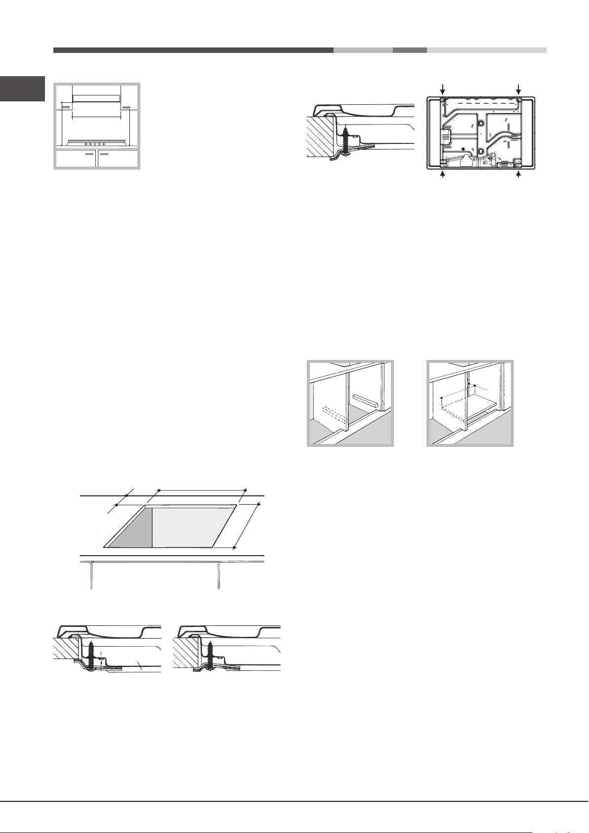
• The installation cavity should have the dimensions
indicated in the gure. Fastening hooks are provided,
allowing you to fasten the hob to tops that are between 20
and 40 mm thick. To ensure the hob is securely fastened
to the top, we recommend you use all the hooks provided.
55 mm
475 mm
Front
Hooking position Back
for top H=40mm
! Use the hooks contained in the “accessory pack”.
• Where the hob is not installed over a built-in oven, a
wooden panel must be installed as insulation. This must
be placed at a minimum distance of 20 mm from the lower
part of the hob.
Ventilation
To ensure adequate ventilation, the back panel of the cabinet
must be removed. It is advisable to install the oven so that it
rests on two strips of wood, or on a completely at surface
with an opening of at least 45 x 560 mm (see diagrams).
45 mm.
560 mm.
Electrical connection
Hobs equipped with a three-pole power supply cable are
designed to operate with alternating current at the voltage and
frequency indicated on the data plate (this is located on the
lower part of the appliance). The earth wire in the cable has a
green and yellow cover. If the appliance is to be installed above
a built-in electric oven, the electrical connection of the hob and
the oven must be carried out separately, both for electrical
safety purposes and to make extracting the oven easier.
Hook fastening diagram
Hooking position Hooking position
for top H=20mm for top H=30mm
8
Connecting the supply cable to the mains
Install a standardised plug corresponding to the load
indicated on the data plate.
The appliance must be directly connected to the mains
using an omnipolar circuit-breaker with a minimum contact
opening of 3 mm installed between the appliance and the
mains. The circuit-breaker must be suitable for the charge
indicated and must comply with current electrical regulations
(the earthing wire must not be interrupted by the circuitbreaker). The supply cable must not come into contact with
surfaces with temperatures higher than 50°C.
! The installer must ensure that the correct electrical
connection has been made and that it is compliant with
safety regulations.

Before connecting to the power supply, make sure that:
• The appliance is earthed and the plug is compliant with
the law.
• The socket can withstand the maximum power of the
appliance, which is indicated on the data plate.
• The voltage is in the range between the values indicated
on the data plate.
• The socket is compatible with the plug of the appliance.
If the socket is incompatible with the plug, ask an
authorised technician to replace it. Do not use extension
cords or multiple sockets.
! Once the appliance has been installed, the power supply
cable and the electrical socket must be easily accessible.
! The cable must not be bent or compressed.
! The cable must be checked regularly and replaced by
authorised technicians only (see Assistance).
! The manufacturer declines any liability should these safety
measures not be observed.
• The exible connection must be approved to class B or
D of AS/NZS1869 as a minimum.
• it should not be bent, kinked or compressed;
• it should not be in contact with the rear wall of the
appliance or in any case with parts which may reach a
temperature of 50°C;
• it should not come into contact with pointed parts or sharp
corners;
• it should not be subject to any pulling or twisting forces;
• it should be easy to inspect along its entire length in order
to be able to check its condition.
• The supply connection point must be accessible with the
appliance installed.
• The inner diameters of the pipe are as follows:
8 mm for LPG;
13 mm for Natural Gas.
Checking the tightness of the connection
Upon completion of installation, check the gas circuit, the
internal connections and the taps for leaks using a soapy
solution (never a ame). Also check that the connecting pipe
cannot come into contact with moving parts which could
damage or crush it. Make sure that the natural gas pipe is
adequate for a sufcient supply to the appliance when all
the burners are lit
AUS
Gas connection
Check The Gas Type
! Before installation, check that the gas type (natural gas
or LPG/Propane) of the cooker is suitable for the gas type
available to the installation. It is extremely dangerous to use
the wrong gas type with any appliance, as re or serious
injury can result.
This cooker is supplied from the factory already set for
Natural Gas. To convert the cooker to LPG (or back to
Natural Gas from LPG), follow the directions later in this
section.
Fit regulator supplied for Natural Gas (if applicable) at rear
of appliance, and as close as practicable to the appliance.
It is recommended that an isolating valve and union be
tted, to enable simple disconnection for servicing. These
are to be in an accessible location.
! Check that the pressure of the gas supply is consistent
with the values indicated in Table 1 (“Burner and nozzle
specications”). This will ensure the safe operation and
longevity of your appliance while maintaining efcient
energy consumption.
Pipe or Hose Connection
This appliance is suitable for use with either a exible
connection or rigid copper connection.
Either a rigid metal pipe with ttings in compliance with the
standards in force must be used for connecting to the nipple
union (threaded ½”G male tting) situated at the rear of the
appliance to the right (g.8), or an approved exible hose
of class B or D.
Should it be necessary to turn the fitting, the gasket
(supplied with the appliance) must be replaced.
If a exible hose is used, it should be as short as possible
with a maximum length of 1.5 metres;
Duplicate Data Plate
Where the data plate is obscured by cabinetry when the
cooker is in the installed position, place a duplicate data
plate on a surface of the cabinetry adjacent to the cooker.
Adapting to different types of gas
To adapt the hob to a different type of gas other than default
type (indicated on the rating plate at the base of the hob or
on the packaging), the burner nozzles should be replaced
as follows:
1. Remove the hob grids and slide the burners off their
seats.
2. Unscrew the nozzles using a 7 mm socket spanner, and
replace them with nozzles for the new type of gas (see
table 1 “Burner and nozzle characteristics”).
3. Reassemble the parts following the above procedure in
the reverse order.
4. Once this procedure is nished, replace the old rating
sticker with one indicating the new type of gas used.
Sticker are available from any of our Service Centres.
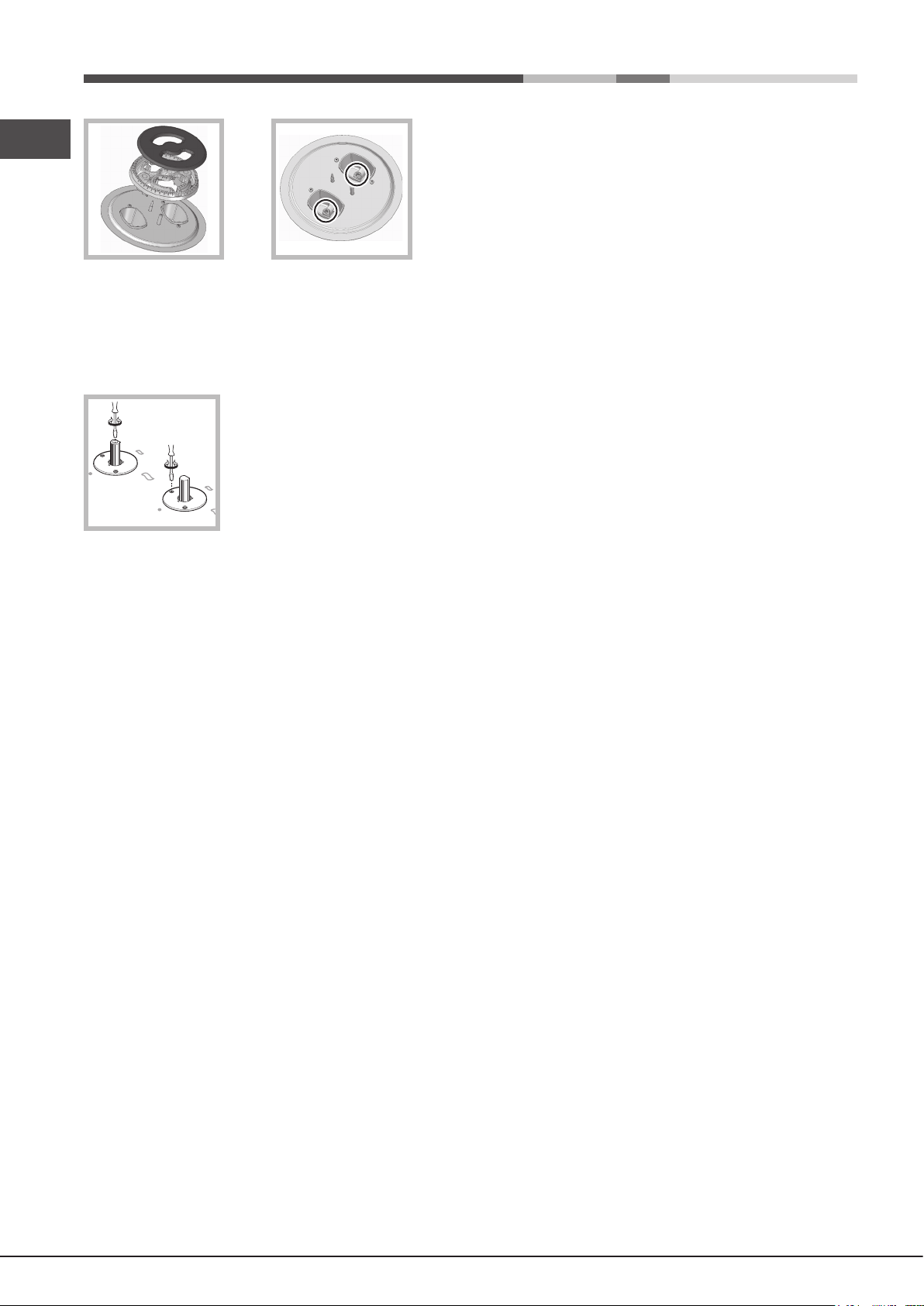
Replacing the Triple ring burner nozzles
1. Remove the pan supports and lift the burners out of their
housing. The burner consists of two separate parts (see
pictures).
2. Unscrew the nozzles using a 7 mm socket spanner.
Replace the nozzles with models that are congured
for use with the new type of gas (see Table 1). The two
nozzles have the same hole diameter.
3. Replace all the components by completing the above
operations in reverse order.
9
AUS
• Adjusting the burners’ primary air :
Does not require adjusting.
• Setting the burners to minimum:
1. Turn the tap to the low ame position;
2. Remove the knob and adjust
the adjustment screw, which is
positioned in or next to the tap pin,
until the ame is small but steady.
3. Having adjusted the ame to the required low setting,
while the burner is alight, quickly change the position
of the knob from minimum to maximum and vice versa
several times, checking that the ame does not go out.
4. Some appliances have a safety device (thermocouple)
tted. If the device fails to work when the burners are set
to the low ame setting, increase this low ame setting
using the adjusting screw.
5. Once the adjustment has been made, replace the
seals on the by-passes using sealing wax or a similar
substance.
! If the appliance is connected to liquid gas, the regulation
screw must be fastened as tightly as possible.
! Once this procedure is nished, replace the old rating
sticker with one indicating the new type of gas used. Stickers
are available from any of our Service Centres.
! Should the gas pressure used be different (or vary slightly)
from the recommended pressure, a suitable pressure
regulator must be tted to the inlet pipe (in order to comply
with current national regulations).
Post Installation Checks
Perform post installation checks and ensure proper and
safe operation before leaving. Test all burners individually
and in combination.
Leak Check
• Ensure all gas control knobs are in the Off position.
• Ensure the gas supply is switched on.
• Spray a solution of soapy water onto all gas joints
as well as the full length of any flexible hoses.
UNDER NO CIRCUMSTANCES USE A NAKED FLAME
IN CHECKING FOR LEAKS.
If bubbles appear anywhere, turn the gas supply off, check
all connections and retest. If satisfactory operation cannot
be achieved, contact place of purchase or their appointed
agent for service.
Flame check
Turn each burner on, and ensure that the ame is blue with
minimal yellow tipping. If there is signicant yellow tipping,
ame lift off or excessive noise, check pressure and adjust
at the regulator if necessary.
If satisfactory operation cannot be achieved, contact place
of purchase or their appointed agent for service.
Igniter operation
Check that the igniter for each burner successfully ignites
the gas.
If an igniter fails to work, rst remove the plug from the
electrical power outlet, and then check that all the electrical
connections are in place.
If satisfactory operation cannot be achieved, contact place
of purchase or their appointed agent for service.
Low ame setting
Check the low ame setting for each hob burner to ensure
that the minimum ame will not be extinguished by air
draughts.
• Light the burner.
• Turn the control until it engages in the minimum position.
• Ensure the ame is stable and will not be extinguished
by air draughts.
To adjust the minimum ame:
Follow the procedure described in the gas conversion
instruction.
10
DO NOT MODIFY THIS APPLIANCE IN ANY
WAY, OTHER THAN AS DESCRIBED IN THESE
INSTRUCTIONS.
 Loading...