


Hotpoint HDA3600HBB, HDA2100HCC, GSD4000KBB, GSD2101VBB Installation
Installation Instructions
Built-In & Spacemaker® Dishwashers
If you have questions, call GE Appliances at 800.GE.CARES (800.432.2737) or visit our website
at: GEAppliances.com. In Canada, please call 800.561.3344 or visit geappliances.ca
BEFORE YOU BEGIN
Read these instructions completely and carefully.
WARNING
• Remove all power leading to the appliance from the
circuit breaker or fuse box before beginning installation.
Failure to do so can result in a risk of electrical shock.
•
To reduce the risk of electric shock, fire, or injury to persons,
the installer must ensure that the dishwasher is completely
enclosed at the time of installation.
• The improper connection of the equipment grounding
conductor can result in a risk of electric shock. Check
with a qualified electrician or service representative
if you are in doubt that the appliance is properly
grounded. If house wiring is not 2-wire with ground, a
ground must be by the installer. When house wiring
is aluminum, be sure to use UL-Listed anti-oxidant
compound and aluminum-to-copper connectors.
•
To reduce the risk of electric shock, fire, or injury to
persons, the installer should check to ensure that wires are
not pinched or damaged, the house wiring is attached to the
junction box bracket through a strain relief, and all electrical
connections made at the time of install (wire nuts) are
contained inside of
the junction box cover.
ADVERTENCIA
• Retire todos los conductores de corriente del
electrodoméstico de disyuntor o de la caja del fusible
antes de comenzar con la instalación. Si no cumple con
esto, se podrá producir el riesgo de descargas eléctricas.
• Para reducir el riesgo de descarga eléctrica, incendio
o lesiones a personas, el instalador debe asegurarse
de que el lavaplatos esté completamente cerrado en
el momento de la instalación.
• La conexión inadecuada del conductor de conexión a
tierra del equipamiento puede provocar un riesgo de
descarga eléctrica. Consulte a un electricista calificado
o representante de servicio técnico si tiene dudas
sobre la correcta conexión a tierra del aparato. Si el
cableado doméstico no cuenta con un cable de 2 hilos
con conexión a tierra, un instalador debe realizar una
conexión a tierra. Cuando el cableado doméstico es de
aluminio, asegúrese de usar un compuesto antioxidante
y conectores de aluminio a cobre aprobados por UL.
• Para reducir el riesgo de descarga eléctrica, incendio
o lesiones a personas, el instalador deberá realizar un
control para asegurar que los cables no estén pellizcados
ni dañados, que el cableado del hogar esté conectado a la
ficha de la caja de empalmes a través de un amortiguador
de refuerzo, y que todas las conexiones eléctricas
realizadas en el momento de la instalación (tuercas para
cables) estén dentro de la tapa de la caja de empalmes.
FOR YOUR SAFETY
Read and observe all WARNINGS and CAUTIONS
shown throughout these instructions.
While performing installations described in this
booklet, gloves, safety glasses or goggles should
be worn.
IMPORTANT – Observe all governing codes and
ordinances.
• Note to Installer – Be sure to leave these instructions
for the consumer’s and local inspector’s use.
• Note to Consumer – Keep these instructions with
your Owner’s Manual for future reference.
• Skill Level – Installation of this dishwasher requires
basic mechanical, electrical and plumbing skills.
Proper installation is the responsibility of the
installer. Product failure due to improper installation
is not covered under the GE Appliances Warranty.
See Warranty information.
• Completion Time – 1 to 3 Hours. New installations
require more time than replacement installations.
IMPORTANT – The dishwasher MUST be installed to
allow for future removal from the enclosure if service is
required.
Care should be exercised when the appliance is installed
or removed,
power supply cord.
If you received a damaged dishwasher, you should
immediately contact your dealer or builder.
Optional Accessories – See the Owner’s Manual for
available custom panel kits.
Your dishwasher is a water heating appliance.
CHECK THE FOLLOWING
Dishwasher is square and level at both the top and
bottom of the cabinet opening, with no twisting or
distortion of the tub or door
All 4 legs of the dishwasher are firmly in contact with the
floor
Drain hose is not pinched between the dishwasher and
adjacent cabinets or walls
to reduce the likelihood of damage to the
READ CAREFULLY
KEEP THESE INSTRUCTIONS
31-31587 01-18 GEA
Installation Preparation
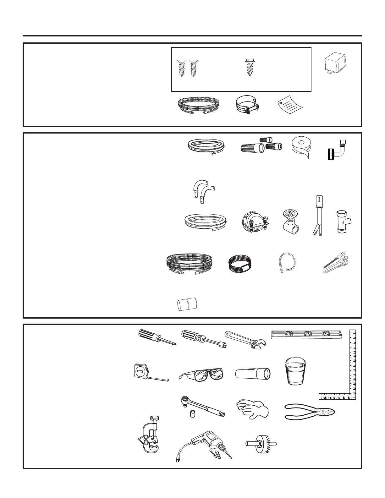
PARTS SUPPLIED IN
INSTALLATION PACKAGE:
• Two 8-18 x 5/8” Phillips-head wood screws
• #10 hex head screw and junction box cover
• Drain hose (78” long)
• Hose clamp
• Literature, product samples and/or coupons
MATERIALS YOU WILL NEED:
• WX09X70910 or WX09X70911 power cord if
applicable to your installation, or electrical cable
• UL-Listed wire nuts (3)
• Thread seal tape
• 90° elbow (¾” hose internal thread on one end,
opposite end sized to fit water supply)
• GPF65 Side-mount bracket kit for use with granite
countertops
For New Installations Only:
• Electrical cable
• Water line–3/8” minimum copper tubing (including
ferrule and compression nut)
• Strain relief for electrical connection
• Hand shut-off valve (recommended)
• Air gap for drain hose, if required
• Waste tee for house plumbing, if applicable
• GPF10S drain hose (10’ long), if needed
• Screw-type hose clamps
• Cord protector (power cord models only
as needed)
• Conversion leads (power cord models only
as needed)
Screw Kit
#8
Phillips-Head
Wood Screws
5/8" long
78" Drain Hose
Electrical Cable
or WR09X70910 or
WX09X70911 Power Cord
GPF65 Side-Mount
Bracket Kit
Hot Water Line–3/8"
Minimum Copper Tubing
Optional 10'
Drain Hose
GPF10S
Coupler for optional
Screw-Type
Hose Clamps
drain hose
Hose Clamp
3 Wire Nuts
Strain Relief
#10
Hex Head
Junction Box Screw
1/2" long
Literature
Thread
Seal Tape
Shut-Off
Valve
Cord Protector
- Optional -
(Power Cord
Models Only)
Junction
Box Cover
90° Elbow
Waste Tee
Air
Gap
Conversion Leads
WD21X10107
- Optional -
(Power Cord
Models Only)
TOOLS YOU WILL NEED:
• Phillips-head screwdriver
• 1/4” and 5/16” nutdriver
• 6” Adjustable wrench
• Level
• Carpenter’s square
• Measuring tape
• Safety glasses
• Flashlight
• Bucket to catch water when flushing the line
• 15/16” socket (optional for skid removal)
• Gloves
• Pliers
For New Installations Only:
• Tubing cutter
• Drill and appropriate bits
• Hole saw set
Phillips-Head
Screwdriver
Measuring Tape
Tubing Cutter
1/4” and 5/16”
Nutdriver
Safety Glasses
15/16” Socket
Drill and Bits
2
6” Adjustable
Wrench
Flashlight
Gloves
Hole Saw Set
Level
Carpenter’s
Square
Bucket
Pliers
Installation Preparation
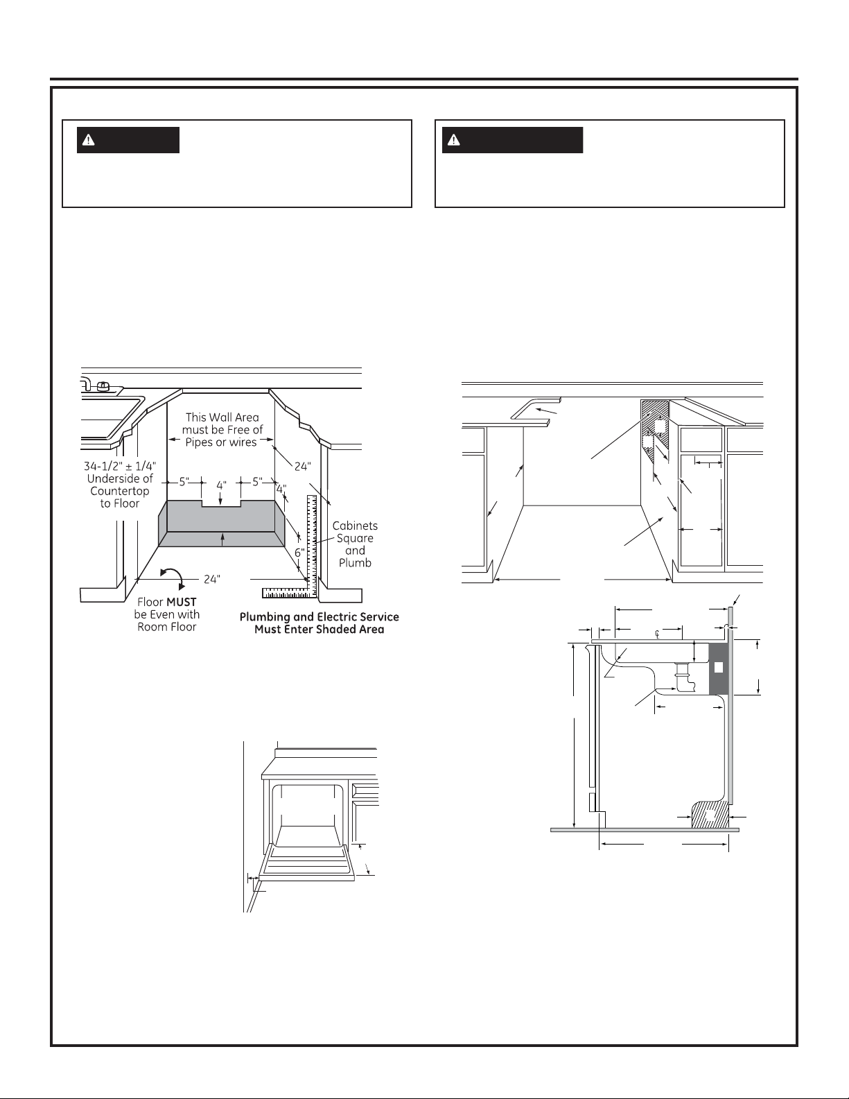
PREPARE DISHWASHER ENCLOSURE
WARNING
To reduce the risk of electric shock, fire, or injury to
persons, the installer must ensure that the dishwasher
is completely enclosed at the time of installation.
ADVERTENCIA
o lesiones a personas, el instalador debe asegurarse
de que el lavaplatos esté completamente cerrado en
el momento de la instalación.
Para reducir el riesgo de
descarga eléctrica, incendio
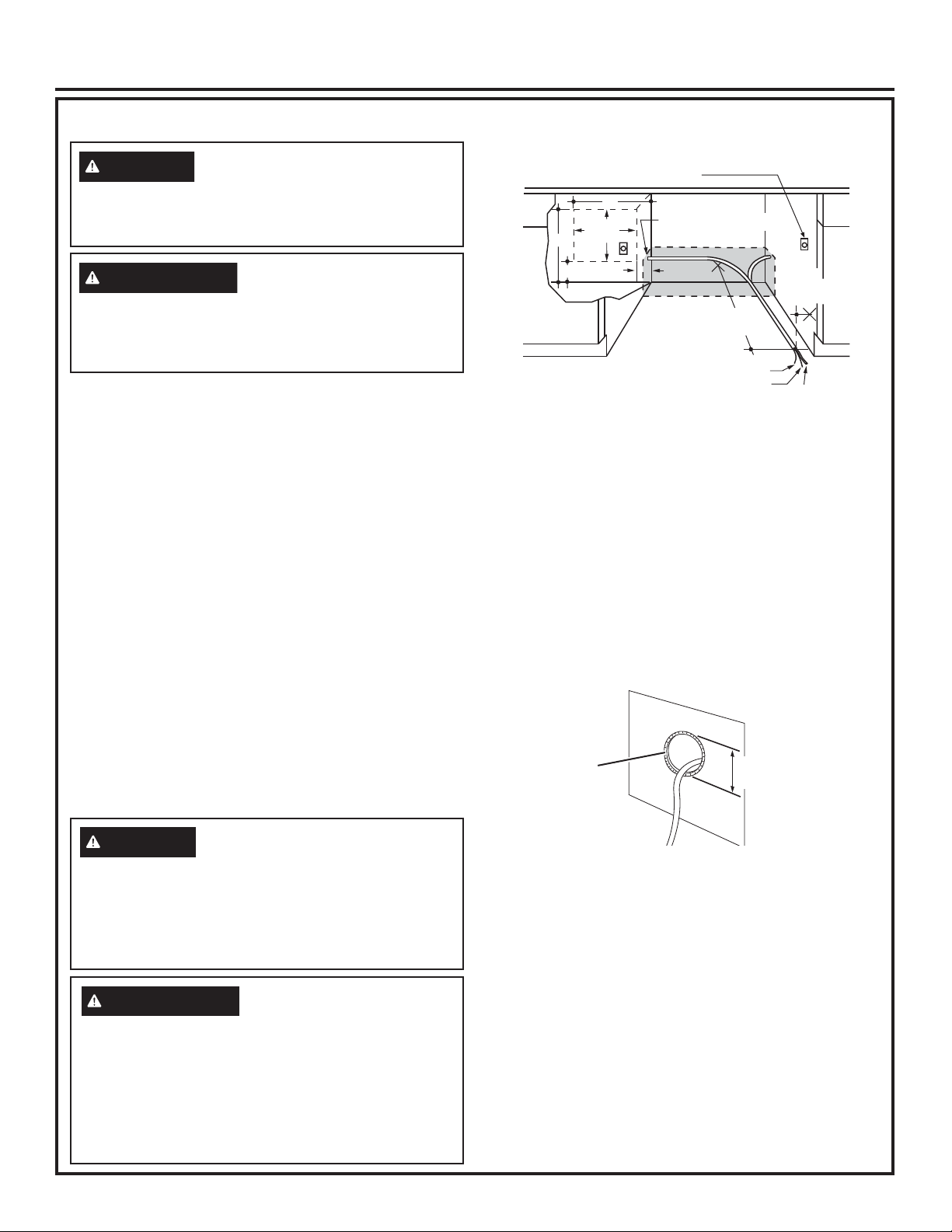
Built-In Models Only: Spacemaker® Models Only:
• The rough cabinet opening must be at least 24” deep,
24” wide and approximately 34-1/2” ± 1/4” high from
floor to underside of the countertop.
• The dishwasher must be installed so that drain hose is
no more than 10’ in length for proper drainage.
• The dishwasher must be fully enclosed on the top, sides
and back, and must not support any part of the enclosure.
• The back wall should be free of pipes or wires.
Min.
Min.
• Adjacent cabinets should be square and plumb to
ensure a good fit.
• Make sure the floor is level inside the opening and
even with the finished floor of the kitchen. This will
facilitate removal of the dishwasher at a later date for
service, if needed.
CLEARANCES:
• When installed into a
Countertop
corner, allow 2” min.
clearance between
Dishwasher
dishwasher and adjacent
cabinet, wall or other
appliances.
27"
• Allow 27” min. clearance
from the front of the
dishwasher for door
Clearance for Door
Opening 2” Minimum
opening.
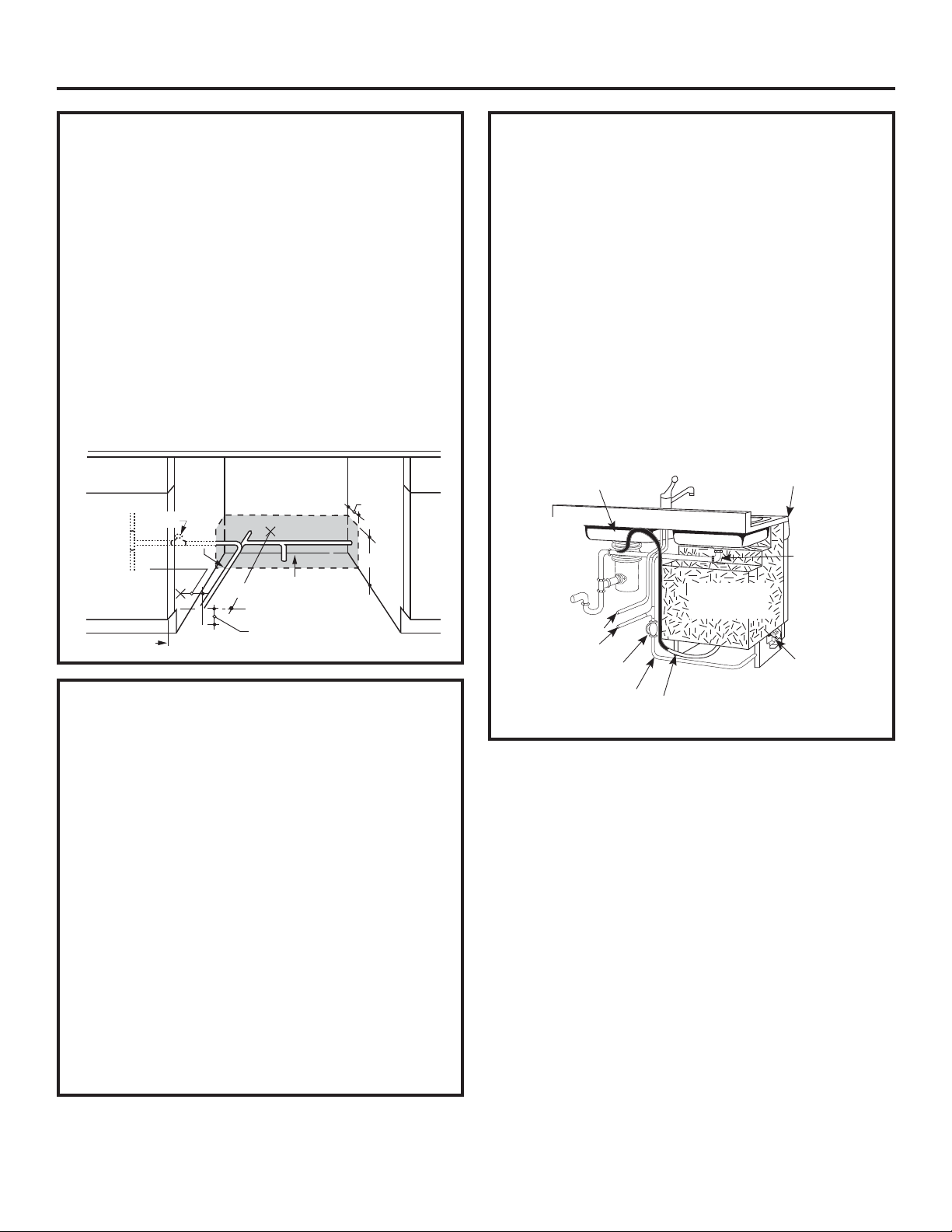
• The rough cabinet opening must be at least 24” deep,
24” wide and approximately 34-1/4” ± 1/4” height.
• This dishwasher fits under a special sink with a depth
of 6” or less in a 1-1/2” countertop.
• The dishwasher must be installed so that drain hose is
no more than 10’ in length for proper drainage.
• The dishwasher must be fully enclosed on the top, sides
and back, and must not support any part of the enclosure.
• The back wall should be free of pipes or wires.
Sink
Installation
Cutout
8" X 20"
24”
min
Adjacent Cabinet
Rear Cutout
Cabinet Side
Adjacent to Dishwasher
24” min
• Water line to
sink faucet
and drain from
sink can be run
3/4" Min.
11" Min.
Drain
through Area
“A.”
• Hot water line
to dishwasher
is installed in
Area “B.”
34-1/4"
+
_
1/4"
1-1/4"
Min. I.R.
1-1/2"
Close Elbow
Dishwasher
• Garbage
disposer, water
lines to faucet,
waste trap, air
gap and water
shut-off valve
are installed in
a 12” wide cabinet, Area “C”.
• Sink opening for garbage disposer must be dimensioned
as shown (7-1/2”) in Area “C.” This will provide clearance
for disposer and plumbing in Area “C” when using either
single or double bowl sink.
• Adjacent cabinets should be square and plumb to
ensure a good fit.
NOTE: A gap between the dishwasher tub front flange and
the front of the base cabinet may result due to either the
cabinet being less than 24” deep or the sink bowl not being
installed to specifications. If the gap is more than 3/4”, the
sink bowl must be relocated to meet specified dimensions.
5"
5"
12-1/2"
20-1/2" Max.
Sink Bowl
6" Max.
11-3/4" Max.
Side View
4"
Max.
24" Min.
C
7-1/2"
7-1/2"
3-1/4"
12"
Plumbing
A
B
Wall
1" Max. To
Sink Flange
10-1/4" MA .
PLUMBING
DEPTH
X
3
Installation Preparation
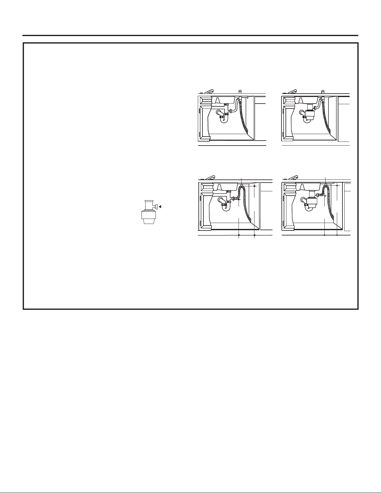
DRAIN REQUIREMENTS
• Follow local codes and ordinances.
• Do not exceed 10’ distance to drain.
• A high drain loop or air gap is required. See below.
DETERMINE DRAIN METHOD
The type of drain installation depends on the following
questions.
• Do local codes or ordinances require an air gap?
• Is waste tee less than 18” above floor?
If the answer to either question is YES, Method 1
MUST be used.
•
If the answers are NO, either method may be used.
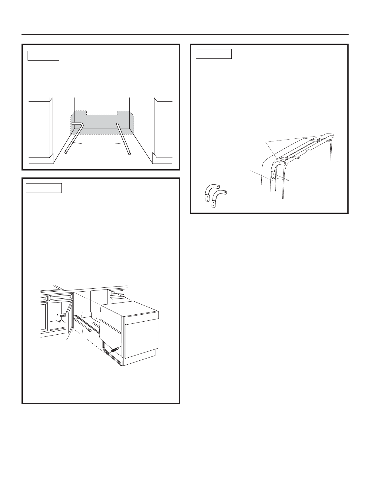
CABINET PREPARATION
• Drill a 1-1/2” diameter hole in the cabinet wall within
the shaded areas shown in PREPARE DISHWASHER
ENCLOSURE section for the drain hose connection.
The hole should be smooth with no sharp edges.
IMPORTANT – When connecting
drain line to disposer, check to be sure
that drain plug has been removed.
DISHWASHER WILL NOT DRAIN IF
PLUG IS LEFT IN PLACE.
Tip: Avoid unnecessary service call charges.
Always be sure disposer drain plug has been removed
before attaching dishwasher drain hose to the disposer.
Remove
Drain
Plug
Method 1 – Air Gap with Waste Tee or Disposer
An air gap must be used when required by local codes
and ordinances. The air gap must be installed according
to manufacturer’s instructions.
Waste Tee Installation Disposer Installation
Method 2 – “High Drain Loop” with Waste Tee or Disposer
Drain Hose Hanger
Min.
18"
Min.
Waste Tee Installation
32"
Drain Hose Hanger
32"
Min.
18"
Min.
Disposer Installation
Special consideration for a dishwasher installed
on a pedestal
lf the dishwasher is installed on an elevated platform,
a high drain loop of at least 32" above the platform
must be provided in addition to the air gap requirement
determined above. This is necessary for proper drain
performance.
4
Installation Preparation
PREPARE ELECTRICAL WIRING
WARNING
Remove all power leading to the appliance from the
circuit breaker or fuse box before beginning installation.
Failure to do so can result in a risk of electrical shock.
ADVERTENCIA
Retire todos los conductores de corriente del
electrodoméstico de disyuntor o de la caja del fusible
antes de comenzar con la instalación. Si no cumple con
esto, se podrá producir el riesgo de descargas eléctricas.
Electrical Requirements
• This appliance must be supplied with 120V, 60 Hz.,
and connected to an individual properly grounded
branch circuit, protected by a 15- or 20-ampere circuit
breaker or time-delay fuse.
• Wiring must be 2 wire with ground and rated for 167°F (75°C).
• If the electrical supply does not meet the above
requirements, call a licensed electrician before proceeding.
Grounding Instructions–Permanent Connection
This appliance must be connected to a grounded metal,
permanent wiring system, or an equipment-grounding
conductor must be run with the circuit conductors and
be connected to the equipment-grounding terminal or
lead on the appliance.
Grounding Instructions–Power Cord Models
This appliance must be grounded. In the event of a malfunction
or breakdown, grounding will reduce the risk of electric shock
by providing a path of least resistance for electric current.
This appliance is equipped with a cord having an equipmentgrounding conductor and a grounding plug. The plug must
be plugged into an appropriate outlet that is installed and
grounded in accordance with all local codes and ordinances.
Alternate Receptacle
Location in Adjacent
Cabinet
18"
1-1/2" Dia. Hole (Max.)
6"
24"
from Wall
Ground
Black
3"
from
Cabinet
White
18"
Receptacle
Location
Area
6"
Cabinet Preparation & Wire Routing
•
The wiring may enter the opening from either side, rear
or the floor within the shaded area illustrated above
in figure and defined in PREPARE DISHWASHER
ENCLOSURE section.
• Cut a 1-1/2" maximum diameter hole to admit the
electrical cable. Edges of hole should be smooth and
rounded. Permanent wiring connections may pass
through the same hole as the drain hose and hot water
line, if convenient. If cabinet wall is metal, the hole
edge must be covered with a bushing.
NOTE: Power cords with plug must pass through a
separate hole in the cabinet.
Metal Cabinet
Wall
Cord Protector
(Obtain locally
as needed)
Hole Diameter
1-1/2” Maximum
WARNING
The improper connection of the equipment grounding
conductor can result in a risk of electric shock. Check with
a
qualified electrician or service representative if you are in
doubt that the appliance is properly grounded. Do not modify
the plug provided with the appliance; if it will not fit the outlet,
have a proper outlet installed by a qualified technician.
ADVERTENCIA
La conexión inadecuada del conductor de conexión
a tierra del equipamiento puede provocar un riesgo de
descarga eléctrica. Consulte a un electricista calificado
o representante de servicio técnico si tiene dudas sobre
la correcta conexión a tierra del aparato. No modifique el
enchufe que se suministra con el aparato; si no calza en el
tomacorrientes, haga que un técnico calificado le instale un
tomacorrientes adecuado.
Electrical Connection to Dishwasher
Electrical connection is on the right front of dishwasher.
• For permanent connections the cable must be routed
as shown in figure. Cable must extend a minimum of
24" from the rear wall.
• For power cord connections, install a 3-prong
grounding type receptacle in the sink cabinet rear wall,
6" min. or 18" maximum from the opening, 6" to 18"
above the floor.
• Use only WXO9X70910 (5’ 5” long) or WX09X70911
(7’ 11” long) Dishwasher Power Cord Kit. Do not use
an extension cord or adapter plug with this appliance.
5
Installation Preparation
PREPARE HOT WATER LINE
NOTE: GE Appliances recommends copper tubing for
the water line, but if you choose to use flexible hose,
use GE Appliances WX28X326, flexible braided hose.
• The water supply line (3/8” copper tubing or flexible
braided hose) may enter from either side, rear or
floor within the shaded area shown in figure.
• The water supply line may pass through the same
hole as the electrical cable and drain hose. Or, cut
an additional 1-1/2" diameter hole to accommodate
the water line. If power cord with plug is used, water
line must not pass through power cord hole.
IMPORTANT: The hot water supply line pressure must
be at least 20 PSI. Lower pressures could cause the
water valve to leak and cause water damage.
1-1/2”
Shut-off
Valve
Hot
2"
From
Cabinet
Cabinet Face
Dia.
Hole
19" From Wall
2" From Floor
4"
6"
WATER LINE CONNECTION
• If using a flexible braided supply hose, label the
hose with the installation date to use as reference.
Flexible braided hoses, elbows and gaskets should
be replaced in 5 years.
• Turn off the water supply.
• Install a hand shut-off valve in an accessible location,
such as under the sink. (Optional, but strongly
recommended and may be required by local codes.)
• Water connection is on the left side of the dishwasher.
Install the hot water inlet line, using no less than
3/8” copper tubing or a flexible braided hose. Route
the line as shown in PREPARE HOT WATER LINE
section and extend forward at least 19” from rear
wall.
• Adjust water heater for 120°F to 140°F temperature.
• Flush water line to clean out debris.
• The hot water supply line pressure must be 20-120
PSI.
SINK UTILITY CONNECTIONS
(Spacemaker
• Sink faucet hot and cold water lines and the sink
drain line must run above and adjacent to the
dishwasher, not behind it. Refer to Areas A and C
in Figure A on page 3 and Figure F1 below. This is
necessary to provide clearance for the dishwasher
when it is installed in the cabinet. Utility lines routed
directly behind the dishwasher will interfere with
placement of the dishwasher in the cabinet and
cause it to extend beyond the adjacent cabinets.
• Figure illustrates an installation using a double bowl
sink, a disposer and a high drain loop.
NOTE: All utility lines are above, below or adjacent to
the dishwasher. None are routed behind it.
6” Double-bowl
stainless steel sink
Cold water
Hot water
Valve to shut off
water to dishwasher
Hot water supply
to dishwasher
®
Models Only)
Spacemaker
dishwasher
Dishwasher
drain hose
Countertop
25” deep
1-1/2” thick
1-1/2” Close
elbow
®
Dishwasher
water inlet
valve
6
Dishwasher Installation
STEP 1
PREPARATION
Locate the items in the installation package:
• Screws
• Junction box cover
• Drain hose and clamp
• Owner’s Manual
• Product samples and/or coupons
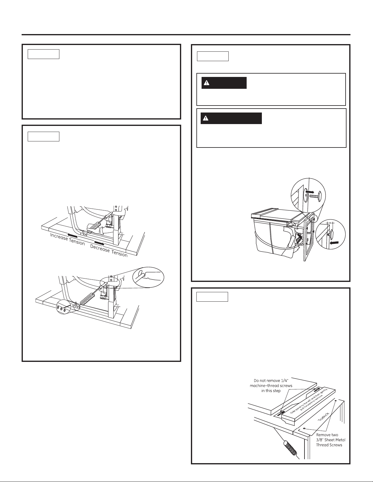
STEP 2
• With dishwasher on the wood base, check the door
balance by opening and closing the door.
• The door is properly balanced if it gently drops from a
1/2 open position and does not rise from the full open
position.
• If necessary increase or decrease tension as shown.
Latch door and adjust both springs to the same
tension setting to correct balance.
CHECK DOOR BALANCE
STEP 3
REMOVE WOOD BASE,
INSTALL LEVELING LEGS
CAUTION
are ready to install the dishwasher. The dishwasher will
tip over when the door is opened if base is removed.
PRECAUCIÓN
hasta que esté listo para instalar el lavaplatos. Si se
quita la base, el lavaplatos se volcará cuando se abra
la puerta.
IMPORTANT – Do not kick off wood base!
Damage will occur.
• Move the dishwasher close to the installation location
and lay it on its
back. NOTE:
Do not place the
dishwasher on its
side.
• Remove the 4
leveling legs on
the underside of
the wood base
with a 15/16”
socket wrench.
• Remove and
discard base.
• Screw leveling legs back into the dishwasher frame,
approximately 3/4” from frame as shown.
Do not remove wood base until you
No quite la base de madera
Link fully seated
in hinge arm
Insert Hook Through
Hole from Inside of Frame
Tip: Avoid service calls for door balance problems.
Make sure the spring end is fully engaged in a frame
hole and the spring link is fully seated in the hinge arm.
STEP 4
REMOVE ACCESS PANEL
AND TOEKICK
The top mounting holes in the access panel are slotted.
• Remove the lower two 10-16 x 3/8” sheet metal
screws. Do not remove the two top 8-32 x 1/4”
machine thread screws.
• Slide the access panel to the left as far as it will go.
• Gently pull the access panel forward to remove it
from the top screws.
Set access panel, toekick and screws aside for use
in Step 20.
Tip: Prevent tub
damage.
Remove only the
3/8” sheet metal
screws in this
step. This will
help prevent a
mix- up with the
1/4” machine
thread screws in
Step 20.
7
Dishwasher Installation
D
STEP 5
Skip this step if the dishwasher will be permanently
connected to the house electrical system or has a
factory-installed power cord.
• In this step you will need the junction box cover and
the #10 x 1/2” hex-head screw from the screw kit set
aside in Step 1.
• The power cord and connections must comply with
the National Electrical Code, Section 422 and/or local
codes and ordinances. Maximum power cord length is
6 feet. Power Cord Kit WX09X70910 or WX09X70911,
available for purchase from an authorized
GE Appliances dealer, meets these requirements.
• Install strain relief in the junction box bracket.
• Insert the power cord through the strain relief and tighten.
• Make sure black, white and green dishwasher wires are
threaded through the small hole in the junction box bracket.
• Connect power cord white (or ribbed) to dishwasher
white, black (or smooth) to dishwasher black and
ground to dishwasher green wire. Use UL-listed wire
nuts of appropriate size.
• Install junction box cover using the #10 hex-head
screw. Be sure wires are not pinched under the cover.
INSTALL POWER CORD
Power Cord or Home Wiring with Strain Relief
Junction
Box
Bracket
Cover
Ground
(Green)
Dishwasher Harness Wires
White Black
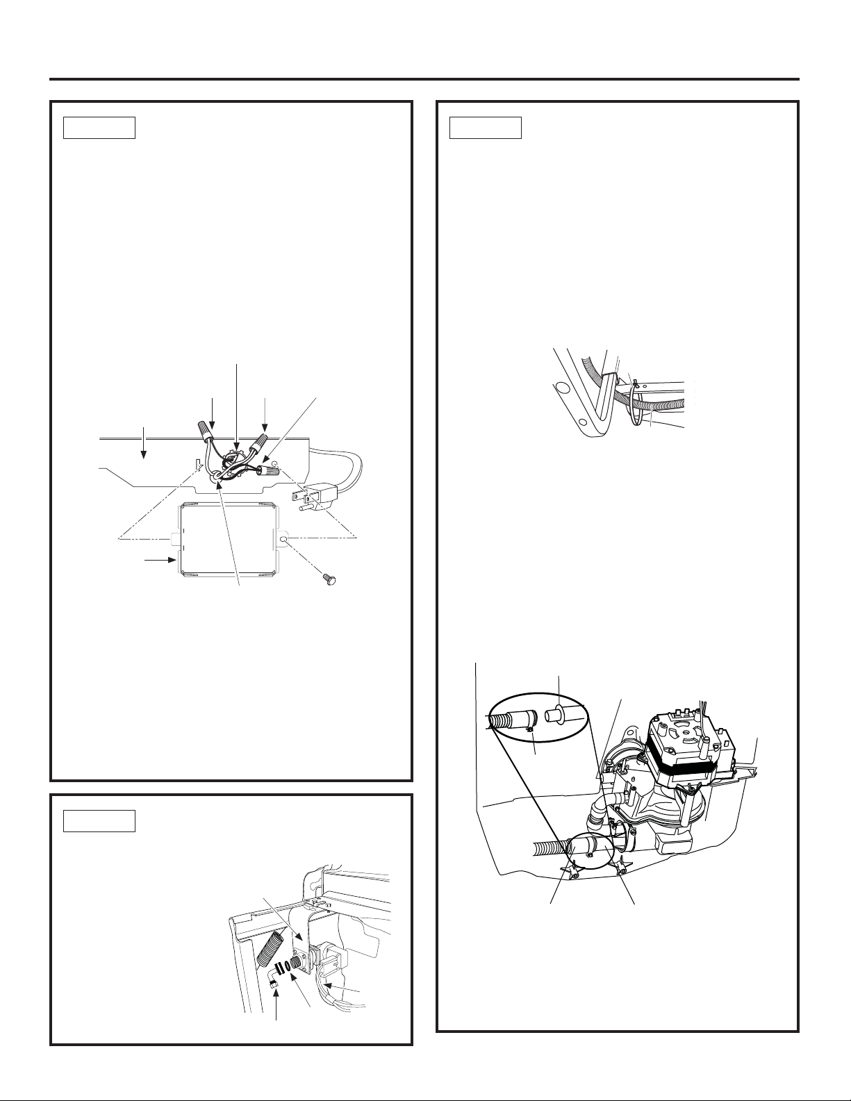
STEP 7
INSTALL DRAIN HOSE TO
DISHWASHER DRAIN PORT
Skip this step if drain hose has been preinstalled.
In this step you will need the drain hose and
clamp set aside in Step 1.
IMPORTANT – Prevent drain hose damage and
possible leaks. Be careful not to nick or cut the
drain hose.
• Route the small end of the drain hose from the
left side of the dishwasher through the strain relief
attached to the dishwasher frame and toward the
center of the dishwasher as shown in the figures.
Strain
Relief
Drain Hose
• Place the hose clamp over the small end of the drain
hose.
• Push the small end of the drain hose over the drain
port on the collection chamber, making sure it is fully
seated against the hose stop.
• Tighten the hose clamp to at least 15 inch-pounds of
torque.
NOTE: The drain hose supplied with the dishwasher
is approximately 78” long. If a longer hose is needed,
a 10-foot-long hose may be purchased from an
authorized GE Appliances dealer. The 10-foot-long
hose is part number GPF10S.
Hose Stop
Hose Clamp
o not use
this port if
present
STEP 6
• Ensure rubber gasket is located between valve and
elbow.
• Thead the 90° elbow
onto the water valve.
• Do not over tighten
the elbow; water valve
bracket could bend or
the valve fitting could
break.
• Position the end of the
elbow to face the rear
of the dishwasher.
INSTALL 90° ELBOW
Water
Valve
Bracket
Gasket
90° Elbow
Fill
Hose
Drain Hose
Tip: Avoid unnecessary service charges for drain
issues.
Make sure the drain hose connection is leak-free and
the hose is routed through the strain relief so it will not
kink when the dishwasher is installed into the cabinet.
Collection Chamber
Drain Port
8
Dishwasher Installation
STEP 8
POSITION WATER LINE
AND POWER SUPPLY
• Position water supply line and house wiring on the
floor of the opening to avoid interference with base
of dishwasher and components under dishwasher.
Water
Power
Line
Supply
STEP 9
INSERT DRAIN HOSE AND
POWER CORD, IF USED,
THROUGH CABINET
• Upright the dishwasher and position it in front of the
cabinet opening.
• Insert the drain hose into the hole previously drilled in
the cabinet wall.
• If a power cord is used, guide the end of the cord
through a separate hole cut for the power cord.
The power cord should be routed directly to the rear
of the junction box, avoiding contact with the door
spring and other dishwasher components.
STEP 10
INSTALL OPTIONAL
GPF65 SIDE MOUNT
BRACKETS
Skip this step if the underside of countertop is
wood or woodlike material.
• Purchase and install the GPF65 side-mount bracket kit
if the underside of counter is granite or a similar material
that will not accept wood screws. The GPF65 kit is
available from authorized GE Appliances dealers.
• Refer to figure and follow the instructions included in the
kit.
Side-Mounting
Brackets
Tub Frame
Optional
Side-Mount
Bracket Kit
Bracket
Attachment
Screws
(2 Each
Side)
Drain
Po w e r
Water
Tip: Avoid unnecessary service charges for no fill,
drain or noise concerns.
Position utility lines so they do not interfere with
anything under or behind the dishwasher.
9
Dishwasher Installation
STEP 11
SLIDE DISHWASHER INTO
CABINET
IMPORTANT – Do not push against front panel with
knees. Damage will occur.
• Grasp the sides of the front panel and slide the
dishwasher into the opening a few inches at a time.
Pull the drain hose and power cord, if equipped,
through the holes in the adjacent cabinet while sliding
the dishwasher into position.
• Check the tub insulation blanket, if equipped, to be
sure it is smoothly wrapped around the tub. It should
not be “bunched up” and it must not interfere with
the door springs. If the insulation is “bunched up” or
interfering with the springs, straighten and re-center
the blanket prior to sliding the dishwasher into its final
position.
• Make sure the drain hose is not kinked under or
behind the dishwasher.
• Make certain the house wiring, drain line and water
line do not interfere with components under the
dishwasher.
• The dishwasher tub flange should be approximately
3/4” behind the face of the adjacent cabinet. Refer to
figure.
Tip: Avoid unnecessary service charges for panel
damage.
Do not press on the center of panel with hands or
knees when sliding dishwasher into position.
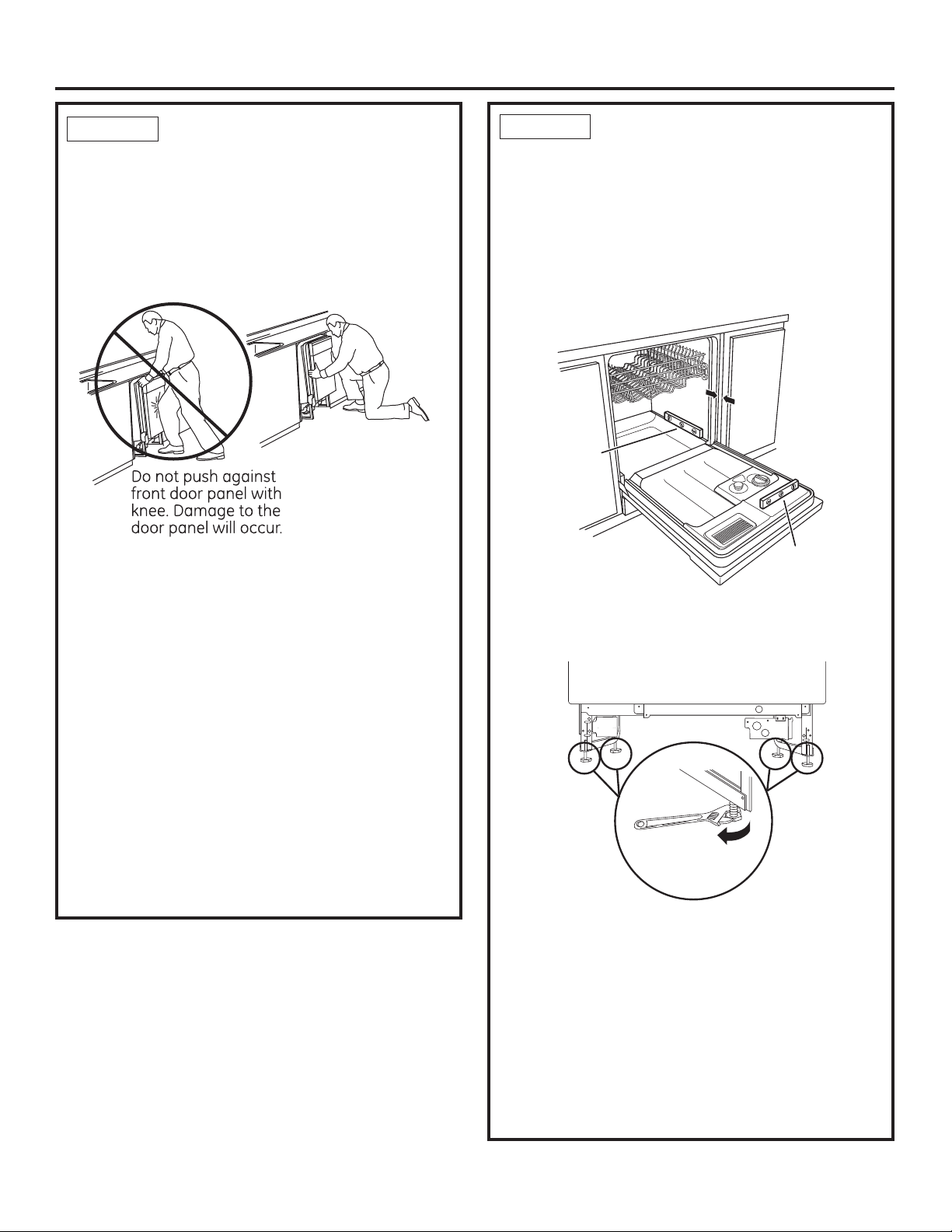
STEP 12
IMPORTANT – Dishwasher must be level for proper
dish rack operation, wash performance and door
operation. The dishwasher must be leveled left to right
and front to back. This ensures the dish racks will not
roll in or out on their own, circulation water will flow to
the pump inlet, and the door will close without hitting
the side of the tub.
• Remove the lower dish rack and place a level on the
door and lower rack track as shown in figure.
Check Level
Front to Back
•
Adjust the level of the dishwasher by individually
turning the 4 legs on the bottom of the dishwasher as
shown. Ensure all 4 legs are firmly in contact with the
floor.
• The dishwasher is properly leveled when the level
indicator is centered left to right and front to back.
Also, the dishwasher door should close without hitting
the side of the tub.
• Replace the lower rack.
Tip: Prevent unnecessary service charges. Verify
dishwasher is leveled.
Pull the dish racks half way out. They should stay put.
Open and close the door. The door should fit in the
tub opening without hitting the side of the tub. If the
racks roll on their own, or the door hits the side of tub,
re-level the dishwasher.
LEVEL DISHWASHER
3/4”
Check Level
Side to Side
Turn Legs
to Adjust
10
 Loading...