

Page 1

Use and Installation Instructions
Please phone us on
08448 24 24 24
to activate your
guarantee
CH60GTCF
CH60GTXF
This appliance must be installed in accordance with the regulations in force and
only used in a well ventilated space.
CC
Read these instructions before installing or using the appliance and retain
them for future reference.
PLEASE PHONE US TO REGISTER YOUR APPLIANCE AND ACTIVATE YOUR PARTS GUARANTEE ON 08448 24 24 24
Page 2

CONTENTS
PAGE
Introduction 3
For Your Safety 4
Installation Instructions 6
Features 13
Control Panel 14
Oven Timer Operation 16
Hotplate 21
Grill 23
Main Oven 25
Main Oven Cooking Chart 27
The “Slow Cook” Setting 29
Top Oven 30
Top Oven Cooking Chart 31
Care and Cleaning 33
Something wrong with your Cooker? 36
Disposal of the appliance 37
Guarantee Information 39
Service Information 40
PLEASE PHONE US TO REGISTER YOUR APPLIANCE AND ACTIVATE YOUR PARTS GUARANTEE ON 08448 24 24 24
2
Page 3

INTRODUCTION
To help you make the best use of your cooker, PLEASE READ THIS BOOKLET CAREFULLY.
Your new cooker is guaranteed and will give lasting service. The guarantee is only applicable if the cooker has
been installed in accordance with the Installation Instructions.
The cooker is designed specifically for domestic use and responsibility will not be accepted for use in any other
installation.
When first using the cooker ensure that the room is well ventilated (e.g. open a window or use an extractor fan)
and that persons who may be sensitive to the odour avoid any fumes. It is suggested that any pets be removed
from the room until the smell has ceased. This odour is due to any temporary finish and also any moisture
absorbed by the insulation.
Our policy is one of continual improvement in design and development, therefore strict accuracy of illustrations
and descriptions cannot be guaranteed.
This appliance conforms to the following EEC directives:
This appliance conforms with the following European Economic Community directives:This appliance conforms with the following European Economic Community directives:
This appliance conforms with the following European Economic Community directives:
This appliance conforms with the following European Economic Community directives:This appliance conforms with the following European Economic Community directives:
- 2006/95/
- 2004/108/
- 90/396/
- 93/68/
- 2002/96/
--
- 1275/2008 (STAnd-by/ Off mode)
--
EC EC
EC of 12/12/06 (Low Voltage) and subsequent modifications;
EC EC
ECEC
EC of 15/12/04 (Electromagnetic Compatibility) and subsequent modifications;
ECEC
EECEEC
EEC of 29/06/90 (Gas) and subsequent modifications (only for models which use gas);
EECEEC
EECEEC
EEC of 22/07/93 and subsequent modifications.
EECEEC
ECEC
EC
ECEC
PLEASE PHONE US TO REGISTER YOUR APPLIANCE AND ACTIVATE YOUR PARTS GUARANTEE ON 08448 24 24 24
3
Page 4

FOR YOUR SAFETY
Please read the precautions below before using your cooker.
ALWAYS . . .
ALWAYS make sure you understand the controls before using the cooker.
ALWAYS check that all controls on the cooker are turned off after use.
ALWAYS stand back when opening an oven door to allow heat to disperse.
ALWAYS use dry, good quality oven gloves when removing items from the ovens.
ALWAYS take care when removing items from the top oven/grill when the main oven is on, as the contents may
be hot.
ALWAYS keep the oven and grill doors closed when the cooker is not in use.
ALWAYS place pans centrally over the hotplate burners and position them so that the handles cannot acciden-
tally be caught or knocked or become heated by other burners.
ALWAYS keep the cooker clean, as a build up of grease or fat from cooking can cause a fire.
ALWAYS allow the cooker to cool before cleaning.
ALWAYS follow the basic principles of food handling and hygiene to prevent the possibility of bacterial growth.
ALWAYS keep ventilation slots clear of obstructions.
ALWAYS turn off the electricity supply before cleaning or replacing an oven lamp.
ALWAYS refer servicing to CORGI registered appliance service engineers.
ALWAYS The appliance must be used by adults only for the preparation of food, in accordance with the instruc-
tions outlined in this booklet. Any other use of the appliance (e.g. for heating the room) constitutes
improper use and is dangerous. The manufacturer may not be held liable for any damage resulting from
improper, incorrect and unreasonable use of the appliance.
PLEASE PHONE US TO REGISTER YOUR APPLIANCE AND ACTIVATE YOUR PARTS GUARANTEE ON 08448 24 24 24
4
Page 5
FOR YOUR SAFETY
NEVER . . .
NEVER leave children unsupervised where the cooker is installed as all surfaces will get hot during and after
use.
NEVER allow anyone to sit or stand on any part of the cooker.
NEVER store items that children may attempt to reach above the cooker.
NEVER heat up unopened food containers as pressure can build up causing the container to burst.
NEVER store chemicals, food stuffs, pressurised containers in or on the cooker, or in cabinets immediately
above or next to the cooker.
NEVER fill a deep fat frying pan more than 1/3 full of oil, and never use a lid. DO NOT LEAVE UNATTENDED
WHILE COOKING.
NEVER place flammable or plastic items on or near the hotplate.
NEVER use proprietary spillage collectors on the hotplate.
NEVER use the cooker as a room heater.
NEVER dry clothes or place other times over or near to the hotplate or oven/gril doors.
NEVER wear garments with long flowing sleeves whilst cooking.
NOTE:NOTE:
NOTE: The use of a gas cooking appliance results in the production of heat and moisture in the room in which it
NOTE:NOTE:
is installed. Always ensure that the kitchen is well ventilated; keep natural ventilation holes open or install a
mechanical ventilation device (mechanical extractor hood).
In particular when using the grill or more than one hotplate burner, open a window if a mechanical ventilation
device is not operating.
! The appliance should not be operated by people (including children) with reduced physical, sensory or mental
capacities, by inexperienced individuals or by anyone who is not familiar with the product. These individuals
should, at the very least, be supervised by someone who assumes responsibility for their safety or receive
preliminary instructions relating to the operation of the appliance.
PLEASE PHONE US TO REGISTER YOUR APPLIANCE AND ACTIVATE YOUR PARTS GUARANTEE ON 08448 24 24 24
5
Page 6

INSTALLATION INSTRUCTIONS
Prior to installation, ensure that the local distribution conditions (nature of the gas and gas pressure) and the
adjustment conditions are compatible. The adjustment conditions for this appliance are stated on the data
badge which is fitted on the back panel.
This appliance is not designed to be connected to a combustion products evacuation device. It must be
installed and connected in accordance with current installation regulations. particular attention should be given
to the relevant requirements regarding ventilation.
MODEL NUMBERS : CH60GTCF & CH60GTXF
Category II2H3+ (GB)
These models are set to burn NATURAL GAS (G20) at 20 mbar but can be converted for use on BUTANE (G30)
at 28-30mbar or PROPANE (G31) at 37mbar with the use of the LPG conversion kit that can be obtained free of
charge, if you contact our Genuine Parts and Accessories department (see Key Contacts, back page).
GAS SAFETY (INSTALLATION & USE) REGULATIONS
It is the law that all gas appliances are installed by competent persons in accordance with the current edition of
the above regulations. It is in your interest and that of safety to ensure compliance with the law.
In the UK, CORGI registered installers work to safe standards of practice. The cooker must also be installed in
accordance with BS 6172. Failure to install the cooker correctly could invalidate the warranty liability claims and
could lead to prosecution.
LOCATION
The cooker may be located in a kitchen, kitchen/diner or a bed-sitting room, but not in a room containing a bath
or shower. The cooker must not be installed in a bed-sitting room of less than 20m3.
When adjusted for use on Butane (G30) or Propane (G31), the cooker must not be installed in a room or internal
space below ground level, e.g. in a basement.
PROVISION FOR VENTILATION
The room containing the cooker should have an air supply in accordance with BS 5440: Part 2.
The room must have an opening window or equivalent; some rooms may also require a permanent vent. If the
room has a volume between 5 and 10m3, it will require an air vent of 50cm2 effective area unless it has a door
which opens directly to outside. If the room has a volume of less than 5m
effective area. If there are other fuel burning appliances in the same room, BS 5440: Part 2 should be consulted
to determine air vent requirements.
3
, it will require an air vent of 100cm
2
PLEASE PHONE US TO REGISTER YOUR APPLIANCE AND ACTIVATE YOUR PARTS GUARANTEE ON 08448 24 24 24
6
Page 7
INSTALLATION INSTRUCTIONS
TECHNICAL DATA
Gas connection Rp ½ (½" BSP female)
Pressure test point Front left hotplate injector
Gas rate adjustment None
Aeration adjustment None
Electrical connection Flexible cord fitted with a 3 pin 13 amp plug
230/240V a.c. 50Hz. 13A fuse.
G20 at 20mbar
BURNER
HOTPLATE
Front Left and Rear Right
HOTPLATE
Front Right and Rear Left
Grill 3.7 kW 150 3.4 kW (200g/h) 91
Main Oven 2.5 kW 115 2.3 kW (165g/h) 71
Top Oven 1.9 kW 100 1.9 kW (135g/h) 66
HEAT INPUT INJECTOR HEAT INPUT INJECTOR
3.05 kW 116 3.0 kW (220g/h) 86
2.0 kW 103 2.0 kW (145g/h) 70
G30 at 28-30mbar
G31 at 37mbar
PLEASE PHONE US TO REGISTER YOUR APPLIANCE AND ACTIVATE YOUR PARTS GUARANTEE ON 08448 24 24 24
7
Page 8
INSTALLATION INSTRUCTIONS
SPACE FOR FIXING
The cooker can be close fitted below hotplate level. This requires a minimum distance of 600mm between cupboard
units of hotplate height.
When installing next to a tall cupboard, partition or wall, for a minimum distance of 400mm above hotplate level,
allow a side clearance of at least 65mm.
The diagram below illustrates the minimum clearance between the cooker and adjacent walls, cupboards etc.
The wall behind the cooker, 50mm below and 450mm above, and the width of the cooker, must be a noncombustible material such as ceramic wall tiles.
If the cooker is to be fitted close to a corner on the left hand side, ensure that there is a clearance of at least 50mm
to allow the main oven door to open fully for when removing oven shelves.
65 mm Min
400 mm Min
840 mm Min
750mm Min
600 mm Min
COOKER HOODS
If a cooker hood is to be installed, refer to the cooker hood manufacturers' instructions regarding fixing height.
PLEASE PHONE US TO REGISTER YOUR APPLIANCE AND ACTIVATE YOUR PARTS GUARANTEE ON 08448 24 24 24
8
Page 9

INSTALLATION INSTRUCTIONS
UNPACKING THE COOKER
Unpack the components from inside the grill and oven. Check that the following parts are present:
Grill pan and grid Top oven/grill shelf heat shield
Baking dish Pan supports
Main oven shelves (2) Enamelled burner caps (4)
Top oven/grill shelf (1) Literature
Aluminium burner bodies (4)
LEVELLING
Four skid feet are fitted which can be adjusted up or down to level the cooker.
CONVERSION FOR USE ON BUTANE (G30) OR PROPANE (G31)
Each burner requires the injector to be replaced and bypass screws adjusted or replaced as follows:
1. Remove the loose hotplate burner parts.
2. Using a 7mm socket, replace the hotplate injectors as appropriate (see table on previous page).
3. Re-position the loose burner parts.
4. Remove the enamelled baffle at the front of the grill (2 screws).
5. Remove the screw on the right hand side of the burner and gently slide the burner off the injector.
6. Using a 7mm socket, replace the grill injector as appropriate (see table on previous page).
7. Re-assemble the burner and baffle.
8. Inside the top oven, remove the central screw securing the burner retainer. Slide the retainer to the right slightly
and lift away.
9. Lift the burner assembly and place on the floor of the oven to the right of the burner opening.
10.Using a 7mm socket, replace the oven injector as appropriate (see table on previous page).
11.Re-assemble the oven burner and retainer.
12.Replace the main oven injector following the same procedure as for the top oven.
13.From behind the cooker, remove the screws securing the rear panel and swing the left hand side outwards
(viewed from the rear) to gain access to the main oven flame supervision device.
14.Replace the flame supervision device bypass screw.
15.Re-assemble the rear panel.
16.Carefully pull off the control knobs and timer buttons.
17.Remove the 2 screws securing the underside of the control panel. Slide the control panel to the left slightly to
remove.
18.Remove the 6 screws securing the timer mounting panel. Without completely removing it, manoeuvre the timer
mounting panel to gain access to the thermostat bypass screws.
19.Using a narrow flat bladed screwdriver rotate the bypass screws fully clockwise. The main oven thermostat
bypass screw is located on the body of the thermostat below the spindle, the top oven thermostat bypass
screw is located on the body of the thermostat to the right of the spindle and the hotplate tap bypass screws are
located down the centre of the spindle.
20.Re-assemble the control panel parts.
21.Secure the self-adhesive LPG conversion label over the gas details on the data badge.
PLEASE PHONE US TO REGISTER YOUR APPLIANCE AND ACTIVATE YOUR PARTS GUARANTEE ON 08448 24 24 24
9
Page 10
INSTALLATION INSTRUCTIONS
STABILITY CHAIN
A hole in the gas inlet valve bracket can be used to engage a stability chain.
CONNECTING TO GAS SUPPLY
670
300
Connection to the cooker should be made with an approved appliance flexible connection to BS 669. A length of
0.9 to 1.25m is recommended. The length of hose chosen should be such that when the cooker is in situ, the
hose does not touch the floor.
Those cookers converted to use on LPG should be connected with a hose suitable for LPG and capable of
withstanding a pressure of 50 mbar.
An adaptor backplate should be fitted within the shaded area shown, to allow the cooker to be pushed fully to
the wall and to ensure that the flexible hose is only likely to come into contact with areas at the rear of the
cooker that do not exceed a temperature rise of 70°C.
PLEASE PHONE US TO REGISTER YOUR APPLIANCE AND ACTIVATE YOUR PARTS GUARANTEE ON 08448 24 24 24
10
Page 11
ELECTRICAL CONNECTION
WARNING - THIS APPLIANCE MUST BE EARTHED. CONNECT TO A 230-240V A.C. SUPPLY
ONLY.
Connection to the electricity supply should be made via a properly earthed, readily accessible wall socket
which is adjacent to but not directly above, and not more than 1.25m away from the appliance and capable of
electrical isolation.
The mains lead should be routed such that it cannot touch hot parts of the cooker i.e. the back panel above a
height of 650mm from the floor.
Should this plug not fit the socket outlet in your home it should be cut off and replaced with a suitable plug as
outlined below.
NOTE: The removed plug cannot be used for any other appliance and should therefore be properly disposed of
and not left where children might find it and plug it into a supply socket - with the obvious consequent danger.
IF THE FITTED PLUG IS REMOVED
The flexible mains lead must be correctly connected as below to a three pin plug of not less than 13 amp
capacity. If a B.S. 1363 fused plug is used, it must be fitted with a fuse which is approved to B.S. 1362.
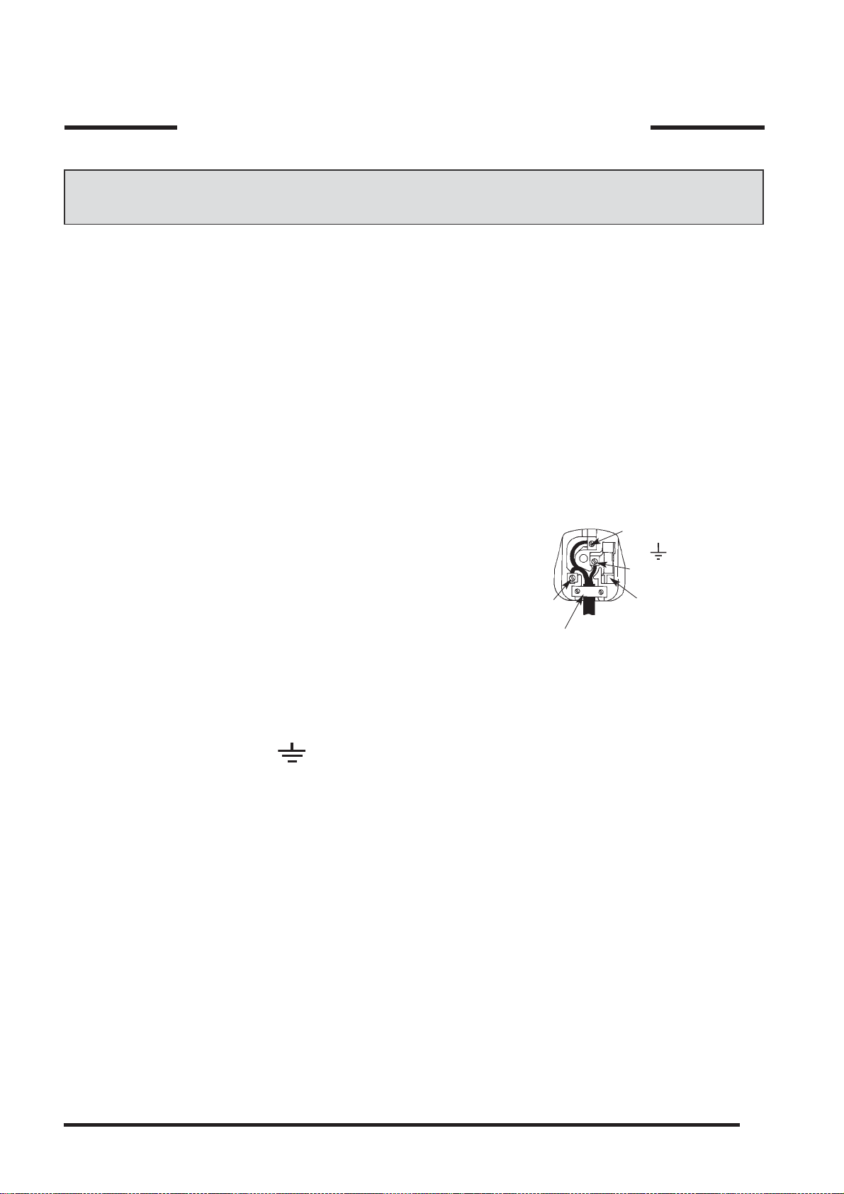
IMPORTANT: The wires in the mains lead fitted to this
appliance are coloured in accordance with the following
code:
GREEN AND YELLOW - EARTH
BLUE - NEUTRAL
BROWN - LIVE
Blue to
Neutral
Cord
Clamp
Green &
Yellow to
Earth
Brown
to Live
13 Amp
Fuse
As the colours of the wires in the mains lead of this appliance may not correspond with the coloured markings
identifying the terminals in your plug, proceed as follows:
The wire which is coloured green and yellow must be connected to the terminal in the plug which is marked with
the letter E or by the earth symbol
or coloured green or green and yellow.
The wire which is coloured blue must be connected to the terminal which is marked with the N or coloured black.
The wire which is coloured brown must be connected to the terminal which is marked with the letter L or
coloured red.
When wiring the plug, ensure that all strands of wire are securely retained in each terminal. Do not forget to
tighten the mains lead clamp on the plug.
As the appliance must be earthed, do not use 2-pin sockets outlets, if you are in doubt, consult a qualified
electrician.
Should the mains lead ever require replacement, it is essential that this operation be carried out by a qualified
electrician and should only be replaced with a flexible cord of the same size i.e. 1.0mm2 cross sectional area
PVC cable, available from our parts department (see Back Cover).
IF A MOULDED PLUG IS FITTED
In the event of replacing a fuse in the plug supplied an ASTA approved fuse to BS1362 must be fitted.
NOTE: The fuse cover must be refitted when changing the fuse. In the event of losing the fuse cover the plug
must not be used until a replacement fuse cover has been obtained and fitted. A new fuse cover can be
obtained from your local Electricity Board. The colour of the correct replacement fuse cover is that of the
coloured marks or inserts in the base of the plug.
Make sure that the cable does not become trapped when pushing the cooker into position.
PLEASE PHONE US TO REGISTER YOUR APPLIANCE AND ACTIVATE YOUR PARTS GUARANTEE ON 08448 24 24 24
11
Page 12

INSTALLATION INSTRUCTIONS
INSTALLATION AND OPERATIONAL CHECKS
After installation, check for gas soundness. The supply pressure can be checked at the front left hotplate
burner injector.
Fit the hotplate burner bodies and caps, pan supports and shelf shield(s). Referring to the instructions for use
where necessary,
1. Check that the hotplate burners ignite and cross-light to all ports. Check for a steady flame on the low setting.
2. Check that the grill burner ignites and cross-lights to all ports and that the flames remain when the control is
released 3 seconds later, Check for a steady flame on the low setting.
3. Check that with the main oven set to mark 9, the burner ignites and that tha flames remain when the control is
released 3 seconds later. Leave the oven full on with the door closed for 10 minutes, and check that when the
control is turned to mark 1 that the flame reduces.
4. Check that with the top oven set to mark 8, the burner ignites and that the flames remain when the control is
released 3 seconds later. Leave the oven full on with the door closed for 10 minutes, and check that when the
control is turned to mark 1 that the flame reduces.
5. Check the operation of the timer and oven light.
Instruct the user on operation of the cooker.
On those models adjusted for use with LPG, it is normal for the oven and grill burners to burn with yellow tips.
PLEASE PHONE US TO REGISTER YOUR APPLIANCE AND ACTIVATE YOUR PARTS GUARANTEE ON 08448 24 24 24
12
Page 13

FEATURES
3000W
Control panel
Grill
Grill pan and
food support
'Stay Clean' liners
Top Oven door
Main Oven door
2000W
3000W
2000W
Timer
Model number &
Serial number label
Top oven/grill
rod shelf
Oven light
Oven fan
Door Switch
'Stay Clean' liners
Main oven
rod shelves
Inner door glass
PLEASE PHONE US TO REGISTER YOUR APPLIANCE AND ACTIVATE YOUR PARTS GUARANTEE ON 08448 24 24 24
13
Page 14

CONTROL PANEL
ELECTRONIC INIECTION BUTTON*
BURNER CONTROLS
9
7
5
MAIN OVEN
CONTROL
S
5
7
TIMER
TOP OVEN/GRILL
CONTROL
Control Knobs for the gas burners
The position of the gas burner controlled by each one of the knobs is shown by a solid ring •. To light one of
the burners, hold a lighted match or lighter near the burner and, at the same time, press down and turn the
corresponding knob counter clockwise to the
maximum maximum
maximum
maximum maximum
E
setting. Each burner can be operated at its
maximum, minimum or intermediate power. Shown on the knob are the different symbols for off • (the knob is
on this setting when the symbol corresponds with the reference mark on the control panel), for
minimum minimum
minimum
and
minimum minimum
turn off the burner, turn the knob clockwise until it stops (corresponding again with the
..
. To obtain these settings, turn the knob counter clockwise with respect to the off position. To
C
..
symbol).
•
maximum maximum
maximum
maximum maximum
E
Electronic Ignition for the Gas Hob*
This device operates when a slight pressure is applied to the button marked with symbol. To light a specific
burner just press the button while pushing the corresponding knob all the way in and turning it counter-
For immediate lighting, first press the button and then turn the knobFor immediate lighting, first press the button and then turn the knob
clockwise until it lights.
For immediate lighting, first press the button and then turn the knob.
For immediate lighting, first press the button and then turn the knobFor immediate lighting, first press the button and then turn the knob
! Should the burner flames accidentally go out, turn off the control knob and wait at least 1 minute
before trying to relight.
Top Oven / Grill Control
This control switches on the top and bottom heating elements in the top oven.
The temperature in the oven can be set anywhere between 100°C and 220°C.
The temperature of the top oven can be set anywhere between 80°C and 230°C by turning the knob clockwise
from 1 to 8.
..
C
.and
..
E
maximum maximum
maximum
maximum maximum
E
setting.
To set the grill turn the corresponding knob to
minimum minimum
The grill can be operated at
minimum
minimum minimum
Main Oven Control
This control switches on the top and rear heating elements at various times in the main oven, dependent on
which mode has been set.
The temperature of the main oven can be set anywhere between 80°C and 230°C by turning the knob clockwise
from 1 to 9.
‘S’ SLOW Setting*‘S’ SLOW Setting*
‘S’ SLOW Setting*
‘S’ SLOW Setting*‘S’ SLOW Setting*
This is used for slow cooking, keeping food warm and warming plates for short periods.
*Only on certain models
PLEASE PHONE US TO REGISTER YOUR APPLIANCE AND ACTIVATE YOUR PARTS GUARANTEE ON 08448 24 24 24
14
Page 15

CONTROL PANEL
The oven timer offers you the following features:
1. Time of Day
2. Automatic Cooking
3. Minute Minder
AUTOMATIC COOKING
The main oven can be controlled automatically.
GUIDANCE ON AUTOMATIC COOKING
1. Select foods which will take the same time to cook.
2. Set the oven timer so that the food has just finished or is just about to finish cooking on your return to the oven.
This will ensure the food has not cooled down and does not require reheating before serving.
3. Food should be as cold as possible when it goes into the oven, ideally straight from the refrigerator. Frozen
meat and poultry should be thawed thoroughly before it is put in the oven.
4. Warm food should never be placed in the oven if there is to be a delay period. Stews prepared by frying the
meat and vegetables should be cooked as soon as possible.
5. Dishes containing left-over cooked poultry or meat, for example Shepherds Pie, should not be cooked automatically if there is to be a delay period.
6. Stews and joints should be cooked by the long slow method, so that the delay period is kept to a minimum.
7. On warm days, to prevent harmful bacterial growth in certain foods (ie poultry, joints, etc) the delayed start
should be kept to a minimum.
8. Wine or beer may ferment and cream may curdle during the delay period, so it is best to add these ingredients
just before serving.
9. Foods which discolour should be protected by coating in fat or tossing in water to which lemon juice has been
added, prior to placing food in the oven.
10.Dishes containing liquid should not be filled too full to prevent boiling over.
11.Food should be well sealed (but not airtight) in a container to prevent the loss of liquid during cooking. Aluminium foil gives a good seal.
12.Ensure food is cooked thoroughly before serving.
PLEASE PHONE US TO REGISTER YOUR APPLIANCE AND ACTIVATE YOUR PARTS GUARANTEE ON 08448 24 24 24
15
Page 16

OVEN TIMER OPERATION
A
U
T
.
000
O
.
000
.
000
A
U
T
.
000
O
(When the 'AUTO' symbol is flashing, to return the oven to Manual operation, turn the oven controls off,
and press the "Manual" button - The 'AUTO' symbol will go out).
CLOCKFACE
The timer incorporates a 24 hour clock.
Ensure the correct time of day is always set, before using your cooker.
SYMBOLS
A 'bell' symbol will light up when you select a Minute Minder Period and will remain lit for the
period set.
At the end of the Minute Minder Period, the timer will emit an audible tone and the 'bell'
symbol will disappear.
The 'cookpot' symbol will light up either:-
- When the timer is in manual mode, or
- During the actual Cook Period.
'AUTO' will light up:-
- When the timer is first turned on it will flash. It will go out when a time of day is set or
when the timer is set to manual.
The 'AUTO' symbol will flash at the end of an Auto Cooking programme to indicate that the
programme has finished.
TIMER FUNCTION BUTTONS
Minute Minder Button
Here you can set a time period of up to 23 hours 59 minutes, that will count down. When it reaches zero, the
timer will emit an audible tone.
For Example: If you set 20 minutes, the audible tone will occur 20 minutes later.
AUTO COOKING PROGRAMME
Cook Period Button
Cook Period is the actual length of time for which, the timer will switch the oven(s) on as part of an "Auto
Cooking" programme. (e.g. If you set 2 hours, the food will be cooked for 2 hours).
End Time Button
The time of day at which you want an "Auto Cooking" programme to end.
For Example: If you set a "Cook Period" for 2 hours, and "End Time" of 11:00. The timer will switch the oven(s)
on at 9:00 and turn the oven(s) off at 11:00. You will hear a audible tone at 11:00, to indicate that the Auto
Cooking Programme has finished.
Notes:
- When setting an Auto Cooking programme you will need to set the oven control(s) to the required temperature(s)
when you set the timer.
- If an Auto Cooking programme has been set the oven(s) will only operate during the pre-programmed time.
Manual Button
Needs to be pressed to cancel an Auto Cooking programme and return the oven(s) to Manual operation.
"+" and "-" Buttons
Used to adjust the various timer function settings.
PLEASE PHONE US TO REGISTER YOUR APPLIANCE AND ACTIVATE YOUR PARTS GUARANTEE ON 08448 24 24 24
16
Page 17

OVEN TIMER OPERATION
SETTING THE TIME OF DAY
A
U
T
.
.
000
O
A
U
T
.
000
O
To change the time of day repeat Steps 4, 5 & 6 above.
Note: You cannot adjust the time of day if the timer has been set for an Auto Cooking Programme.
SETTING THE MINUTE MINDER
.
000
A
U
T
.
000
O
Step 1 Make sure all oven controls are turned Off.
Step 2 Check the electricity supply to the cooker is turned on.
Step 3 When switched on the display will show 0.00 and the Auto symbol, flashing
intermittently.
Step 4 Press & hold in both the Cook Period & End Time buttons together.
Step 5 With the Cook Period & End Time buttons still held in, press either the "+" or "-"
buttons to set the correct time of day.
Step 6 Release all the buttons simultaneously. THE TIME OF DAY IS NOW SET.
Step 1 Ensure the time of day is set correctly.
Step 2 Press and hold the Minute Minder button.
Step 3 With the Minute Minder button held in, set the required Minute Minder period using
the "+" and "-" buttons. A 'bell' symbol will light up.
Release all buttons and the timer display will revert back to the time of day. The 'bell' symbol
will remain lit to signify that a Minute Minder period has been set.
At the end of the set time an audible tone will be heard, and the 'bell' symbol will disappear.
Step 4 To cancel the audible tone press the Minute Minder button.
Note 1 When the Minute Minder has been set, the time remaining can be checked at any time by simply pressing
the Minute Minder button.
Note 2 If necessary the Minute Minder can be cancelled before the tone sounds by pressing and holding the
Minute Minder button and then at the same time pressing the "-" button until 0.00 appears in the display
window.
PLEASE PHONE US TO REGISTER YOUR APPLIANCE AND ACTIVATE YOUR PARTS GUARANTEE ON 08448 24 24 24
17
Page 18

OVEN TIMER OPERATION
AUTO COOKING PROGRAMMES
There are two Auto Cooking programmes that can be selected using your timer:-
(a) To set the timer to switch the oven(s) On and Off Automatically
(b) To set timer to switch on immediately and OFF automatically after a set cook period.
a) TO SET THE TIMER TO SWITCH THE OVEN(S) ON AND OFF AUTOMATICALLY
This allows you to cook at a specified time for a chosen period before the oven switches off
Automatically.
Step 1 Check that the correct time of day is set, if not follow instructions for setting the time of day.
Step 2 Place food onto the correct shelf position in the oven and close the oven door(s).
.
000
A
U
T
.
4120
O
A
U
T
.
6120
O
A
U
T
.
4120
O
Step 3 Press and hold in the Cook Period button. The display will read 0.00 with the
'cookpot' symbol lit.
Step 4 With the Cook Period button still held in, set the required Cook Period using the "+"
and "-" buttons.
Release the buttons and the timer display will revert to the time of day with the 'Auto'
symbol and 'cookpot' symbol lit.
Step 5 Press and hold in the End Time button. The display will read the earliest possible
end time for the Cook Period that you have set above. The 'Auto' symbol and 'cookpot'
symbol will be lit.
Step 6 With the End Time button still held in, use the "+" and "-" buttons to set the 'End
Time' (i.e. The time you require the oven to switch off ).
Release all the buttons and the timer will revert back to the time of day.
The 'Auto' symbol will remain lit to signify that an Auto Cooking Programme has been set.
The 'cookpot' symbol will go out.
Step 7 Turn the oven control(s) to the required temperature, and if necessary select the
appropriate oven function.
A
U
T
.
6120
O
.
6120
PLEASE PHONE US TO REGISTER YOUR APPLIANCE AND ACTIVATE YOUR PARTS GUARANTEE ON 08448 24 24 24
At the end of the Automatic Cook Period the Auto Symbol will flash and an intermittent
bleeping sound will be heard.
The audible tone will continue unless cancelled.
The 'Auto' symbol will continue to flash until the timer is returned to Manual operation (see
below).
Step 8 Press the Manual button, the audible tone will be cancelled and the oven(s) will be
returned to Manual.
Step 9 Turn the oven control(s) to the OFF position.
18
Page 19

OVEN TIMER OPERATION
Note 1 When cooking automatically the Cook Period can be checked at any time by simply pressing the
Cook Period button.
Note 2 When cooking automatically the End Time can be checked at any time by simply pressing the
End Time button.
b) TO SET TIMER TO SWITCH ON IMMEDIATELY AND OFF AUTOMATICALLY AFTER A SET
COOK PERIOD
Step 1 Check that the correct time of day is set, if not follow instructions for setting the time of day.
Step 2 Place food onto the correct shelf position in the oven and close the oven door(s).
Step 3 Turn the oven control(s) to the required temperature, and if necessary select the appropriate oven
function.
Step 4 Press & hold in the Cook Period button, the display will read 0.00 and the 'cookpot'
.
130
symbol will light up.
With the Cook Period button still held in set the required Cook Period using the "+" and "-"
buttons. Example: 1hr 30 minutes (as shown).
Step 5 Release all buttons.
A
U
T
.
4120
O
NOTE: The Cookpot symbol disappears
A
U
T
.
6120
O
.
6120
Step 7 Turn the oven control(s) to the OFF position.
The timer display will revert to the time of day with the 'Auto' symbol lit & 'cookpot' symbol
remaining lit.
At the end of the Cook Period the 'Auto' symbol will flash and an intermittent audible tone
will be heard. The audible tone will continue until cancelled. The 'Auto' symbol will continue
to flash until the timer is returned to Manual operation (see below).
Step 6 Press the Manual button. The audible tone will be cancelled and the oven(s) will be
returned to Manual.
PLEASE PHONE US TO REGISTER YOUR APPLIANCE AND ACTIVATE YOUR PARTS GUARANTEE ON 08448 24 24 24
19
Page 20

OVEN TIMER OPERATION
TO CANCEL AN AUTO COOKING PROGRAMME BEFORE THE COOK
PERIOD HAS FINISHED.
Step 1 Turn the oven control to the OFF position.
.
5100
Step 2 Press the Manual button to return the oven to "Manual" operation. The 'Auto' symbol will go out.
Note 1 When cooking automatically the Cook Period can be checked at any time by simply pressing
the Cook Period button.
OTHER NOTES ON TIMER OPERATION
1. When cooking Automatically the Cook Period can be checked at any time simply by pressing the Cook Period
button.
2. When cooking Automatically the End Time can be checked at any time by simply pressing the End Time button.
3. Having set a Cook Period and End Time an electronic device stores the information. The device within the timer
will switch the oven(s) on and off at the required times.
4. When setting an Auto Cooking Programme and a mistake is made, to clear:(a) Press & release the Manual button.
(b) Start the sequence again.
5. If at any time the display shows three flashing zero's 0.00 and 'Auto', it is likely that the electricity supply to the
oven has been interrupted. Reset the timer to the correct time of day.
have been cooked, before serving check food is thoroughly heated and completely cooked.
6. To set each function always press and hold the required function button and at the same time press "+" or "-"
buttons.
Food in the oven may, therefore, not
PLEASE PHONE US TO REGISTER YOUR APPLIANCE AND ACTIVATE YOUR PARTS GUARANTEE ON 08448 24 24 24
20
Page 21

HOTPLATE
The hotplate lid is fitted with a safety device which cuts off the gas supply to the hotplate burners unless the lid
is fully open. Do not use the safety device as a means of controlling the hotplate burners.
The hotplate has two high speed burners and two simmering burners which will accommodate pans between
100mm (4”) and 240mm (9 ½”) diameter. All pans should be positioned centrally over the burners.
TO USE THE HOTPLATE
1. Remove any items or spillage from the top of the lid and then raise it to its fully open position.
2. Push in and turn the control knob of the chosen burner anti-clockwise to the large flame symbol. Continue to
press the ignition button until the sparks light the gas.
3. Turn the control knob anti-clockwise to reduce the heat input. Only turn the control knob between the large flame
symbol and the small flame symbol when adjusting the setting.
4. To turn off, turn the control knob fully clockwise to the symbol O.
DO NOT use the hotplate unless all pan supports are in position.
DO NOT use mis-shapen pans which may be unstable.
DO NOT use round base woks directly on the pan supports.
DO NOT use the glass lid as a working surface.
Each burner is fitted with a spark ignitor for lighting the gas. To ensure rapid lighting of the burners every time
they are used, the ignitors must be kept clean and dry. Remove any food spillage or cleaning materials from
the ignitor using a small nylon brush such as a tooth brush. Access to the ignitor can be achieved by lifting off
the loose burner parts carefully when the burners are cool.
When the hotplate burner bodies and caps are removed for cleaning, be careful not to drop any food particles
or cleaning materials into the burner bases, to avoid the possibility of blocking the gas jets.
If aluminium based pans are used, a silvery deposit may appear on the top edge of the pan support fingers.
See 'Care and Cleaning' section for cleaning information.
Models with Hob Gas Burner Safety Devices to Prevent Leaks *
These models can be identified by the presence of the device itself.
! Since the hob burners are equipped with a safety device, you must hold the control knob in for about 3-7
seconds after the burner has been lighted to allow the gas to pass until the safety thermocouple has heated.
HOB GAS BURNER
SAFETY DEVICE
ELECTRONIC
LIGHTING DEVICE
PLEASE PHONE US TO REGISTER YOUR APPLIANCE AND ACTIVATE YOUR PARTS GUARANTEE ON 08448 24 24 24
21
Page 22

HOTPLATE
SAFETY REQUIREMENTS FOR DEEP FAT FRYING
1. Never fill chip pans more than one third full with oil or fat.
2. Never leave oil or fat unattended during the heating or cooling period.
3. Never heat fat or fry with a lid on the pan.
4. Always dry food thoroughly before frying, and lower it slowly into the hot oil or fat. Frozen foods in particular will
cause frothing and spitting if added too quickly.
5. Always keep the outside of the pan clean and free from streaks of oil or fat.
HOW TO DEAL WITH A FAT FIRE
1. Do not move the pan.
2. Turn off the hotplate burners.
3. Smother the flames with a fire blanket or damp cloth to extinguish the fire. Do not use water or a fire extinguisher
as the force of it may spread the burning fat or oil over the edge of the pan.
4. Leave the pan for at least 60 minutes before moving it.
PLEASE PHONE US TO REGISTER YOUR APPLIANCE AND ACTIVATE YOUR PARTS GUARANTEE ON 08448 24 24 24
22
Page 23

GRILL
CAUTION - ACCESSIBLE PARTS MAY BECOME HOT WHEN THE GRILL IS USED.
YOUNG CHILDREN SHOULD BE KEPT AWAY.
The grill is fitted with a safety device that will cut off the gas supply to the burner if the flame is extinguished for
any reason. Each time the grill is used, the safety device has to be activated by pushing and holding in the
control knob for 3 seconds after the gas has lit.
A gentle flow of air will be blown from underneath the control panel when the grill or top oven is in use. If the fan
fails to blow air when the grill is in use, you should contact your service engineer immediately.
PLEASE PHONE US TO REGISTER YOUR APPLIANCE AND ACTIVATE YOUR PARTS GUARANTEE ON 08448 24 24 24
23
Page 24

TO USE THE GRILL
1. Open the top oven/grill door and remove the grill pan.
2. Remove the heat shield from the rear of the shelf for maximum grilling area and place the shelf in appropriate position
- (Chesterfield only).
3. Push in and turn the control knob clockwise to the large flame symbol. Continue to push in the control knob for a
further 3 seconds after the gas has lit, to allow time for the safety device to operate. If the burner extinguishes when
the control knob is released, repeat the procedure ensuring the control knob is fully depressed and allowing more
time for the safety device to operate.
4. Slide the grill pan along the shelf towards the rear of the grill compartment until it stops.
5. Turn the control knob anti-clockwise to reduce the heat input. Only turn the control knob between the large flame
symbol and the small flame symbol when adjusting the setting.
6. To turn off, turn the control knob anti-clockwise to the symbol O.
The grill cannot be used at the same time as the top oven. If for any reason the grill burner has not lit after 15
seconds, turn the control knob to the off position, leave the grill door open and wait for at least a minute before
attempting to light the burner again. An odour may be noticed when first using the grill - this should cease after
a short period of use.
DO NOT use the grill with the door closed.
DO NOT cover the grill pan or grid with aluminium foil as this can hold fat, intensify the heat and create a fire
hazard.
RELIGHTING THE BURNER
In the event of the burner flames being accidentally extinguished, turn off the burner control and do not attempt to reignite the burner for at least one minute.
Grilling can be started from cold but for best results preheat for approximately two minutes. Most cooking is done
with the heat on full, but it may be desirable to reduce it for thicker pieces of meat or for keeping food warm.
For au gratin dishes eg. Macaroni Cheese and meringue toppings eg. Baked Alaska, place the dish on the floor of
the grill compartment. The base of the grill pan can be used for warming fruit garnishes on the reduced setting.
REMOVE HEAT SHIELD
FROM SHELF WHEN
GRILLING FOR MAXIMUM
GRILLING AREA - (Chesterfield only).
NOTE: Strong detergents used in dishwashers may damage the grill pan grid finish; clean in soapy water as
described in CARE AND CLEANING section.
PLEASE PHONE US TO REGISTER YOUR APPLIANCE AND ACTIVATE YOUR PARTS GUARANTEE ON 08448 24 24 24
24
Page 25

MAIN OVEN
The main oven is fitted with a safety device that re-lights the burner if the flame has been extinguished for any
reason and another safety device that reduces the gas flow to a safe level if, for any reason, the burner fails to
light.
The oven has different heat zones - the thermostat settings refer to the temperature on the middle shelf position;
above this shelf it is hotter and below it is cooler. Two shelves provide five possible cooking levels enabling full
use of the different temperatures inside the oven.
Each shelf has a safety stop to prevent if from being pulled out too far when attending to food. Shelves are
removed from the oven by pulling them out to the stop and then lifting them at the front to withdraw.
The maximum size of baking tray that should be used is 325mm x 350mm (13” x 14”).
TO USE THE MAIN OVEN
1. Check that the timer is set to manual.
2. Place the oven shelves in the appropriate positions (refer to cooking charts).
3. Push in and turn the oven control knob fully anti-clockwise. Sparking will continue until the burner is lit.
4. Turn the control knob clockwise to the required setting (refer to cooking chart). There is a delay of about one minute
whilst the safety device operates before the burner comes on full.
5. To turn off, turn the control knob fully clockwise the the symbol O.
Never place dishes over the burner.
An odour may be noticed when first using the oven - this should cease after a short period of use.
The oven temperature control marking are gas marked 0 to 9.
The equivalent degrees Celsius (sometimes called Centigrade) and degrees Fahrenheit are shown below as a guide.
Lower
Oven
Se tting
Slow cook
1
2
3
4
5
6
7
8
9
Te mperature
°C
110
145
160
175
190
205
222
240
250
260
Te mperature
°F
230
293
320
347
374
401
432
464
482
500
PLEASE PHONE US TO REGISTER YOUR APPLIANCE AND ACTIVATE YOUR PARTS GUARANTEE ON 08448 24 24 24
25
Page 26

MAIN OVEN
COLD START COOKING
Anything requiring long slow cooking such as casseroles and rich fruit cakes can be put into a cold oven.
Satisfactory results can also be obtained with creamed mixture, rich pastries or yeast mixtures, but for
perfection we recommend preheating the oven for about 15 minutes at the gas mark you require for cooking.
ROASTING OF LARGE POULTRY
The maximum weight of poultry that can be accommodated is 11.5kg (25 lbs) of suitable shape.
It is important to check that the bird DOES NOT overhang the burner at the back of the oven.
STORAGE AND RE-HEATING OF FOOD
It is vitally important to strictly adhere to the basic principles of food handling and hygiene to prevent the
possibility of bacterial growth.
1. If food is to be frozen or not served immediately, cool it in a clean container as quickly as possible.
2. Completely thaw frozen food in the refrigerator before re-heating.
3. Re-heat food thoroughly and quickly either on the hotplate or in a hot oven, Mk. 6, and then serve immediately.
4. Only re-heat food once.
'COOK CHILL' DISHES
These should always be placed in a pre-heated oven ideally on the first or second shelf position. Follow the
packet instructions for cooking time.
ALUMINIUM FOIL
If using Aluminium Foil:
1. Remember that it is important to increase the cooking time by one third.
2. Never allow the foil to touch the sides of the oven.
3. Never cover the oven interior with foil.
4. Never cover the oven shelves with foil.
PLEASE PHONE US TO REGISTER YOUR APPLIANCE AND ACTIVATE YOUR PARTS GUARANTEE ON 08448 24 24 24
26
Page 27

MAIN OVEN COOKING CHART
The following times and setting are for guidance only. You may wish to alter the setting to give a result more to
your satisfaction. When a different setting to that shown below is given in a recipe, the recipe instructions
should be followed. Allow 15 minutes preheat for best results.
Always turn the thermostat knob to Mark 9 first, before turning back to the required Gas Mark.
Shelf position 1 is the highest.
Food
STARTERS
Patés and Terrines 3 or 4 4 1 ½ - 2 hrs
FISH
Oily Fish (whole) 4 or 5 3 25 mins - 1 hr, depending on recipe and size of fish.
White Fish (fillets & steaks) 4 or 5 3 25 - 30 mins.
MEAT AND POULTRY
Veal 5 4 25 mins per lb (450g) + 25 mins.
Beef 4 or 5 4 25 - 30 mins per lb (450g) + 25 mins.
Ham 5 4
Lamb 5 4 30 - 35 mins per lb (450g) + 30 mins.
Pork 5 4 40 mins per lb (450g) + 40 mins.
Chicken 5 4 25 mins per lb (450g) + 25 mins.
Gas
Mark
Shelf
Positions
Approx. Cooking Time and Comments
40 mins per lb (450g) covered in foil + 40 mins per lb (450g)
uncovered.
Duckling & gosling 5 4 25 mins per lb (450g) + 25 mins.
Turkey 4 or 5 4 or 5 15 - 20 mins per lb (450g) + 20 mins.
Game b irds 6 4
Casseroles 3 3 or 4 1 ½ - 6 hrs. (depending on type of meat)
PUDDINGS
Milk Puddings 3 3 or 4 2 ¼ - 2 ½ hrs stand dish on a baking tray and started with warm milk
Baked Custard 3 3 or 4 45 mins in bain-marie
Baked sponges 4 3 40 - 45 mins
Baked Apples 3 4 30 - 45 mins depending on the size and type of apples
Meringue puddings 1 4 or 5 15 mins or until 'tinged' with brown
Apple Pie 1x9" (230 mm) 6 3 45 - 55 mins stand dish on a baking tray
Fruit crumbles 5 or 6 3 35 - 45 mins
PLEASE PHONE US TO REGISTER YOUR APPLIANCE AND ACTIVATE YOUR PARTS GUARANTEE ON 08448 24 24 24
50 mins Removed bacon for last 15 mins. Add extra 15 mins if roasting
brace
27
Page 28

MAIN OVEN COOKING CHART
Food
CAKES, PASTRIES AND BISCUITS
Small cakes - 2 trays 5 1 & 3 17 - 25 mins
- 1 tray 5
Victoria sandwich 2x8" (205mm) 4 1 & 3 25 - 35 mins.
Fatless sponge 2x7" (180mm) - 3 egg mix 5 2 20 - 25 mins. 2 tins side by side
Christmas cake 2 3 or 4 4 - 6½ hrs depending on recipe
Madeira cake 7" 4 3 1¼ - 1½ hrs.
Rich Fruit cake 9" (230mm) 2 3 3 - 3½ hrs.
Shortcrust pastry 6 2 or 3 15 mins - 1 hr depending on recipe
Rich Shortcrust
pastry - 1 tray
Flaky & puff
pastry - 2 trays
Flaky & puff
pastry - 2 trays
Choux pastry - éclairs
1 tray
Scones - 2 trays 7 1 & 3 10 - 15 mins
Gas
Mark
5 2 20 - 40 mins. depending on recipe
7 1 & 3 10 - 30 mins. depending on recipe
6 2 35 - 40 mins
Shelf
Positions
2 or 3
only
2 or 3 " " " "
Approx. Cooking Time and Comments
"
Scones - 1 trays 2 or 3 "
Shortbread - 7"
(180mm) round
Biscuits - 2 trays 4 1 and 3 15 - 20 mins depending on recipe
Biscuits - 1 trays 2 or 3 " " " "
YEAST MIXTURES
Bread 7 or 8 3 or 4 45 - 50 mins
Rolls 7 or 8 3 or 4 15 - 20 mins
Chelsea buns 5 2 or 3 30 - 40 mins
MISCELLANEOUS
Yorkshire Pudding - large 7 1 or 2 45 - 50 mins
Yorkshire Pudding - individual 7 1 or 2 25 - 30 mins
Soufflés 4 3 30 mins
Meringues
Baked P otatoes 4 or 5 3 1½ - 4 hrs until soft, depending on size
2 4 55 - 1hr depending on thickness
Slow
Cook
4 &
baseplate
2 - 5 hrs starting on shelf 4 until 'set' and then on the
baseplate until dried out - turn when necessary.
When baking with two trays or tins on two levels, the top tray is removed first and the lower tray moved up to
the top position for a few minutes longer.
Soft Margarine - Use the oven settings recommended by the margarine manufacturer and not those indicated
on the cooking chart.
PLEASE PHONE US TO REGISTER YOUR APPLIANCE AND ACTIVATE YOUR PARTS GUARANTEE ON 08448 24 24 24
28
Page 29

THE ‘SLOW COOK’ SETTING
The 'Slow Cook' setting on the main oven thermostat is used for slow cooking, keeping food warm and warming
plates for short periods.
USING THE 'SLOW COOK' SETTING FOR SLOW COOKING
1. All dishes cooked by the 'Slow Cook' setting should be cooked for a minimum 6 hours. They will 'hold' at this
setting for a further hour but marked deterioration in appearance will be noticed in some cases.
2. Joints of meat and poultry should be cooked at Mk. 6 for 30 minutes before turning to the 'Slow Cook' setting
and never be cooked lower than the middle shelf position.
3. Joints of meat over 6 lbs (2.7kg) and poultry over 4 lbs 8oz (2 kg) should not be cooked using the 'Slow Cook'
setting.
4. Always stand covered joints on a rack over the meat tin to allow good air circulation.
5. A meat thermometer should be used when cooking pork joints and poultry. The internal temperature of the food
should reach at least 88°C.
6. This method is unsuitable for stuffed meat and stuffed poultry.
7. Always bring soups, casseroles and liquids to the boil before putting in the oven.
8. Cover casseroles with foil and then the lid to prevent loss of moisture.
9. Always thaw frozen food completely before cooking.
10.Root vegetables will cook better if cut into small pieces.
11.Adjust seasonings and thickenings at the end of the cooking time.
12.Use the zones of heat in the oven, e.g. meringues and milk puddings can be cooked lower in the oven whilst
other dishes requiring greater heat can be cooked above them.
13.Egg and fish dishes need only 1-5 hours cooking and should be included in day cooking sessions, when they
can be observed from time to time.
14.Dried red kidney beans must be boiled for a minimum of ten minutes after soaking, before inclusion in any dish.
PLEASE PHONE US TO REGISTER YOUR APPLIANCE AND ACTIVATE YOUR PARTS GUARANTEE ON 08448 24 24 24
29
Page 30

TOP OVEN
The top oven can be used to cook small quantities of food or used in conjunction with the main oven to provide
additional cooking space.
The top oven is fitted with a safety device that will cut off the gas supply to the burner if the flame is
extinguished for any reason. Each time the top oven is used, the safety device has to be activated by pushing
and holding in the control knob for 3 seconds after the gas has lit.
A gentle flow of air will be blown from underneath the control panel when the grill or top oven is in use.
The shelf in the top oven has a heat shield fitted at the rear. The shield can be removed
for cleaning and grilling, but should be replaced when using the oven for best cooking
results. It has a safety stop to prevent it from being pulled out too far when attending to
food.
The shelf is removed from the oven by pulling it out to the stop and then lifting at the
front to withdraw.
The maximum size of baking tray that should be used is 300mm x 350mm (12” x 14”).
TO USE THE TOP OVEN
1. Remove the grill pan and check that the heat shield is fitted to the shelf.
2. Place the top oven shelf in the appropriate position (refer to cooking chart).
3. Push in and turn the control knob fully anti-clockwise. Continue to push in the control knob for a further 3
seconds after the gas has lit to allow time for the safety device to operate. If the burner extinguishes when the
control knob is released, repeat the procedure ensuring the control knob is fully depressed and allowing more
time for the safety device to operate.
4. Turn the control knob clockwise to the required setting. (refer to cooking chart).
5. To turn off, turn the control knob clockwise to the symbol O.
Always push the door firmly closed to ensure that there is no loss of heat through the door seal.
If for any reason the oven burner has not lit after 15 seconds, turn the control knob to the OFF position. Leave
the top oven door open and wait at least one minute before attempting to light the burner again.
GUIDANCE ON USING THE TOP OVEN
1. Best results are obtained by pre-heating the oven for about 15 minutes.
2. Food which is higher than or will rise above 125mm (5") cannot be cooked in the top oven.
Never place dishes over the burner.
An odour may be noticed when first using the oven - this should cease after a short period of use.
RELIGHTING THE BURNER
In the event of the burner flames being accidentally extinguished, turn off the burner control and DO NOT
attempt to re-ignite the burner for at least one minute
The equivalent degrees Celsius (sometimes called Centigrade) and degrees Fahrenheit are shown below as a
guide..
Upper
Oven
S etting
1
2
3
4
5
6
7
8
PLEASE PHONE US TO REGISTER YOUR APPLIANCE AND ACTIVATE YOUR PARTS GUARANTEE ON 08448 24 24 24
30
Tem perature
°C
120
140
160
175
190
205
215
225
Tem perature
°F
248
284
320
347
374
401
419
437
Page 31

TOP OVEN COOKING CHART
The following times and setting are for guidance only. You may wish to alter the setting to give a result more to
your satisfaction. When a different setting to that shown below is given in a recipe, the recipe instructions
should be followed.
Allow 15 minutes preheat for best results. Always turn the thermostat knob to Mark 8 first, before turning back
to the required Gas Mark.
Food
STARTERS
Oily and white fish 5 2 20 - 30 mins.
MEAT AND POULTRY
Beef (medium) 4 or 5 3 25 - 30 mins per lb + 25 - 30 mins.
Ham (covered in foil) 5 3 40 mins per lb + 40 mins
Lamb 5 3 30 - 35 mins per lb + 30 mins.
Pork 5 3 40 mins per lb + 40 mins.
Chicken 5 3 25 mins per lb + 25 mins.
Duckling & Goose 5 3 25 mins per lb + 25 mins.
Turkey 4 3 15 - 20 mins per lb + 15 - 20 mins.
Casseroles 3 3 2 - 4 hrs. depending on meat used
VEGETABLES
Gas
Mark
Shelf
Positions
Approx. Cooking Time and Comments
Baked jacket potatoes 5 2 1 ½ hrs.
PUDDINGS
Milk Puddings (500ml/1pt) 3 2 1 ½ hrs.
Baked Custard
(500ml/1pt)
Baked Sponge Puddings 4 2 30 - 45 mins
Baked Apples 3 2 45 mins - 1 hr. depending on size
Meringue Topped
Puddings
Apple Tart (1x205 mm)/8") 6 2 60 mins
Fruit Crumble 5 2 45 - 50 mins
If using aluminium foil:
3 2 45 mins - 1 hr. in bain-marie of cold water
1 2 25 mins until tinged with brown
1. Remember it is important to increase the cooking time by one third.
2. Do not allow the foil to touch the sides of the oven.
3. Do not cover the oven interior with foil.
4. Do not cover the oven shelves with foil.
PLEASE PHONE US TO REGISTER YOUR APPLIANCE AND ACTIVATE YOUR PARTS GUARANTEE ON 08448 24 24 24
31
Page 32

TOP OVEN COOKING CHART
Food
CAKES, PASTRIES AND BISCUITS
Small Cakes (16 per tray) 5 2 20 - 25 mins
Victoria sandwich (2x180mm / 7 ") 4 2 25 - 30 mins.
Swiss Roll (3 egg quantity) 6 2 10 - 12 mins.
Christmas cake (1 x 205mm / 8") 2 2 or 3 4 - 5 hrs depending on recipe
Madeira cake (1 x 180mm / 7") 4 2 1 hr.
Rich Fruit cake (1 x 180mm / 7") 2 2 or 3 2¼ - 2½ hrs.
Gingerbread 3 2 1½ - 1¾ hrs.
Scones - 16 per tray 7 2 12 - 15 mins.
Shortbread (1 x 180mm / 7") 2 2 45 mins. - 1hr depending on thickness
Biscuits 4 - 6 2 15 - 25 mins.
Shortcrust Pastry 6 2 15 mins. - 1 hr. depending on recipe
Gas
Mark
Shelf
Positions
Approx. Cooking Time and Comments
Rich Short Crust 5 2 20 - 30 mins.
Flaky/Puff Pastry 7 2 10 - 30 mins. depending on recipe
Choux Pastry 6 2 25 - 35 mins.
YEAST MIXTURES
Bread - rolls, plait 7 2 or 3 25 - 35 mins
Tea breads etc. 5 2 25 - 30 mins
MISCELLANEOUS
Yorkshire Pudding - small 7 2 20 - 25 mins
Yorkshire Pudding - large 7 2 30 - 40 mins
Meringues 1 2 2½ - 4 hrs turn when necessary.
Soft Margarine - Use the oven settings recommended by the margarine manufacturer and not those indicated
on the cooking chart.
PLEASE PHONE US TO REGISTER YOUR APPLIANCE AND ACTIVATE YOUR PARTS GUARANTEE ON 08448 24 24 24
32
Page 33

CARE AND CLEANING
! Never use steam cleaners or pressure cleaners on the appliance.
!
Clean the glass part of the oven door using a sponge and a non-abrasive cleaning product, then dry thoroughly with
a soft cloth. Do not use rough abrasive material or sharp metal scrapers as these could scratch the surface and
cause the glass to crack.
! The accessories can be washed like everyday crockery (even in your dishwasher).
! Switch off the electricity supply and allow to cool before cleaning the cooker.
! Clean the cooker regularly and wipe up spills soon after they occur to prevent them from becoming
burnt on. Never use biological washing powder, caustic cleaners, harsh abrasives, scouring pads,
steam cleaners, aerosol cleaners or oven chemical cleaners of any kind.
! If it is necessary to remove the cooker for cleaning, ensure that it is cool and beware that it is heavy
(approximately 70 kg 155 lbs).
! To move the cooker forward, open the top oven/grill door and with both hands positioned under the roof of the
compartment, lift and pull forward. Replace by pushing the cooker backwards.
! Check that the cooker is level. Take care not to damage any floor coverings.
OVEN HEAT CLEAN LININGS
The oven side linings are coated with a special enamel which has a continuous cleaning action.
The higher the oven temperature the more effective the action. In most cases this cleaning operation will proceed
during normal cooking. However, if roasting is done frequently, or high temperatures are not used regularly, it may be
necessary to occasionally operate the oven empty at Mark 8 for about an hour.
It should not normally be necessary to clean the linings with water, but if desired, wipe them over with a soapy cloth,
followed by a wipe with a damp clean cloth.
OVEN DOORS
The door inner glass panels can be removed for ease of cleaning by simply sliding the panels out of the frame.
REPLACEMENT OF OVEN LIGHT BULB
CAUTION: DISCONNECT THE APPLIANCE FROM THE ELECTRICITY SUPPLY BEFORE
REPLACING THE LAMP TO AVOID THE POSSIBILITY OF AN ELECTRIC SHOCK.
Light bulbs are not covered by the manufacturer's guarantee.
A new 25W, 300°C rated SES bulb can be obtained from your cooker supplier or any major electrical retailer.
1. Remove the shelves from the oven.
2. Unscrew the lens using a thick cloth to protect your fingers in the unlikely event of a lens fracture.
3. Unscrew bulb.
4. Fit new bulb and refit lens.
PLEASE PHONE US TO REGISTER YOUR APPLIANCE AND ACTIVATE YOUR PARTS GUARANTEE ON 08448 24 24 24
33
Page 34

CARE AND CLEANING
BURNER MAINTANANCE INSTRUCTIONSBURNER MAINTANANCE INSTRUCTIONS
BURNER MAINTANANCE INSTRUCTIONS
BURNER MAINTANANCE INSTRUCTIONSBURNER MAINTANANCE INSTRUCTIONS
Before cleaning the burners ensure the appliance is switch off and isolated from the electriaclBefore cleaning the burners ensure the appliance is switch off and isolated from the electriacl
Before cleaning the burners ensure the appliance is switch off and isolated from the electriacl
Before cleaning the burners ensure the appliance is switch off and isolated from the electriaclBefore cleaning the burners ensure the appliance is switch off and isolated from the electriacl
supply and the appliance is cold.supply and the appliance is cold.
supply and the appliance is cold.
supply and the appliance is cold.supply and the appliance is cold.
MAIN OVENMAIN OVEN
MAIN OVEN
MAIN OVENMAIN OVEN
When the main oven is used regularly, its burner is susceptible to being covered with grease and dirt.
This might result in problems with the burner’s ignition as well as the uneven or disappearing flame.
To solve the problem clean the burner with a small amount of water- diluted cleaner (e.g. CIF) using a small
brush (e.g. a toothbrush). After cleaning wipe the burner with a cloth to remove the detergent waste and let it
dry for at least 2 hours.
WARNING!WARNING!
WARNING!
WARNING!WARNING!
1. Brush the burner in the directions indicated below.
2. DO NOT re-ignite the burner with the detergent residue.
TOP OVEN/GRILLTOP OVEN/GRILL
TOP OVEN/GRILL
TOP OVEN/GRILLTOP OVEN/GRILL
When the Top oven/grill is used regularly, its burner is susceptible to being covered with grease and dirt.
This might result in problems with the burner’s ignition as well as the uneven or disappearing flame.
To solve the problem clean the burner with a small amount of water- diluted cleaner (e.g. CIF) using a small
brush (e.g. a toothbrush). After cleaning wipe the burner with a cloth to remove the detergent waste and let it
dry for at least 2 hours.
WARNING!
1. Brush the burner in the directions indicated below.
2. DO NOT re-ignite the burner with the detergent residue.
PLEASE PHONE US TO REGISTER YOUR APPLIANCE AND ACTIVATE YOUR PARTS GUARANTEE ON 08448 24 24 24
34
Page 35

CARE AND CLEANING
COOKER FINISH CLEANING METHOD
Vitreous Enamel
Door inner panels, pan supports, burner caps,
roasting dish, grill pan, main oven base, inside
of grill compartment.
Paint
Side panels.
Aluminium
Hotplate burner bodies, lid rear trim.
Glass
Chromium Plating
Oven shelves, grill pan grid, grill pan handle ,
grill pan handle support.
Cloth wrung out in warm soapy water. Stubborn stains can be
removed with a cream paste, liquid cleaner or by rubbing with
fine steel wool soap pads.
Check that the cleaning agent is approved by the Vitreous
Enamel Association.
Wash with a cloth wrung out in warm soapy water only.
DO NOT USE ABRASIVES.
Similar to paint cleaning above. Use a nylon brush to remove any
cleaning materials, water or dirt from the hotplate burner bodies.
As for enamel cleaning. Polish with a clean dry cloth or kitchen
roll.
Wipe with a cloth wrung out in warm soapy water. A fine steel
wool soap pad e.g. Brillo, Ajax, or a chrome or stainless steel
cleaner may be used.
Plastic
Control knobs.
Stainless Steel
Hotplate, control panel.
PLEASE PHONE US TO REGISTER YOUR APPLIANCE AND ACTIVATE YOUR PARTS GUARANTEE ON 08448 24 24 24
Wipe with a cloth wrung out in warm soapy water.
Wipe with a cloth wrung out in warm soapy water. Polish with a
clean dry cloth or kitchen towel. For stubborn stains, use a
proprietary stainless steel cleaner and follow the instructions on
the container.
35
Page 36

SOMETHING WRONG
WITH YOUR COOKER
Before contacting your nearest Service Centre/Installer, check the problem guide below; there may be
nothing wrong with your cooker.
PROBLEM CHECK
Burner will not light: If all burners fail to ignite:
Check that sparks appear at the burners; a clicking noise should
be heard.
If not;
Check that the electricity supply is turned on.
If the electricity supply has failed, all burners can be lit by a match.
If only one burner fails to ignite
Check that the burner is dry and that spillage of food or cleaning
Hotplate burner:
fluid remains are not affecting the ignitor or burner ports.
Clean away any debris with a dry nylon brush such as an old
toothbrush. If a wire wool pad has been used for cleaning around
the burner ensure the ignitor is free from any stray strands. Any
water on the burner should be dried with a cloth or kitchen towel.
Make sure that all the burners parts are correctly seated.
Burner ports Ignitor
PROBLEM CHECK
Slight odour or small amount of smoke when
grill / oven used first time.
Oven cooks too fast or too slow.
Cannot set an "Auto Cook" programme or
cannot get the timer to turn the oven on or off
at the required times.
This is normal and should cease after a short period.
Check that the oven temperature and shelf positions are as
recommended in the Oven Cooking Charts. However, it may be
necessary to increase or decrease the recommended setting
slightly to suit your taste.
Read the Timer instructions in this book carefully remembering that
the Cook period is the length of time that the timer will switch the
oven(s) on as part of an Auto Cooking Programme.
:
Timer Display shows "0:00" with "Auto"
Flashing.
Main oven does not work, but the grill, top oven
and hotplate burners work.
Oven lamp does not work.
PLEASE PHONE US TO REGISTER YOUR APPLIANCE AND ACTIVATE YOUR PARTS GUARANTEE ON 08448 24 24 24
The electricity supply to the cooker may have been interrupted, but
has now come back on again. set the correct time of day by
following the instructions given in the timer section of this book.
The timer may be set for an Auto Cooking Programme. Check the
timer to see if "AUTO" is illuminated. If it is, follow the instructions
given in the timer section of this book to cancel the Auto Cooking
Programme.
The oven lamp is not covered by the guarantee. The part is easily
changed (see the section on oven lamp replacement). A new lamp
may be obtained from our Spare Parts department, see Key
Contacts (back page).
36
Page 37

DISPOSAL
Disposal of your product
To minimise the risk of injury to children please dispose of your product carefully and safely. Remove all doors
and lids. Remove the mains cable (where fitted) by cutting off flush with the appliance and always ensure that
no plug is left in a condition where it could be connected to the electricity supply.
To help the environment, Local Authority instructions should be followed for the disposal of your product.
Disposal of old electrical appliances
The European Directive 2002/96/EC on Waste Electrical and Electronic Equipment (WEEE), requires that old
household electrical appliances must not be disposed of in the normal unsorted municipal waste stream. Old
appliances must be collected separately in order to optimise the recovery and recycling of the materials they
contain and reduce the impact on human health and the environment.
The crossed out "wheeled bin" symbol on the product reminds you of your obligation, that when you dispose of
the appliance it must be separately collected.
Consumers should contact their local authority or retailer for information concerning the correct disposal of their
old appliance.
PLEASE PHONE US TO REGISTER YOUR APPLIANCE AND ACTIVATE YOUR PARTS GUARANTEE ON 08448 24 24 24
37
Page 38

PLEASE PHONE US TO REGISTER YOUR APPLIANCE AND ACTIVATE YOUR PARTS GUARANTEE ON 08448 24 24 24
38
Page 39

Guarantee
12 months Parts and Labour Guarantee
Your appliance has the benefit of our manufacturer's guarantee, which covers the cost of
breakdown repairs for twelve months from the date of purchase.
This gives you the reassurance that if, within that time, your appliance is proven to be
defective because of either workmanship or materials, we will, at our discretion, either repair
or replace the appliance at no cost to you.
The guarantee is subject to the following conditions:
- The appliance has been installed and operated correctly and in accordance with our oper-
ating and maintenance instructions.
- The appliance is only used on the electricity or gas supply printed on the rating plate.
- The appliance has been used for normal domestic purposes only.
- The appliance has not been altered, serviced, maintained, dismantled or otherwise inter-
fered with by any person not authorised by us.
- Any repair work must be undertaken by us or our appointed agent.
- Any parts removed during repair work or any appliance that is replaced become our prop-
erty.
- The appliance is used in the United Kingdom or Republic of Ireland.
The guarantee does not cover:
- Damage resulting from transportation, improper use, neglect or interference or as a result of
improper installation.
- Replacement of any consumable item or accessory. These include but are not limited to:
plugs, cables, batteries, light bulbs, fluorescent tubes and starters, covers and filters.
- Replacement of any removable parts made of glass or plastic.
THE GUARANTEE WILL NOT APPLY IF THE APPLIANCE HAS BEEN USED IN
COMMERCIAL OR NON-DOMESTIC PREMISES.
5 Year Parts Guarantee
Hotpoint also offers you a FREE 5 year parts guarantee. This additional guarantee is conditional
on you registering your appliance with us and the parts being fitted by one of our authorised
engineers. There will be a charge for our engineer's time. To activate the extra parts warranty on
your appliance, simply call our registration line on 08448 24 24 24 (ROI 01 230 0800)
Extended Guarantees
We offer a selection of protection plans that enable you to fully cover yourself against the expense
of repair bills for the life of your policy. To find the ideal plan for you please call our advice line on
08448 226 226 (ROI 01 230 0233)
Free Helpdesk Service
We have a dedicated team who can provide free advice and assistance with your appliance if
you experience any technical difficulties within the first 90 days of ownership.
Simply call our Hotpoint Service Hotline on 08448 224 224 (ROI 0818 313 413) for telephone
assistance, or, where necessary, to arrange for an engineer to call.
PLEASE PHONE US TO REGISTER YOUR APPLIANCE AND ACTIVATE YOUR PARTS GUARANTEE ON 08448 24 24 24
39
Page 40

05/2011- 195088179.00
XEROX FABRIANO
After Sales Service
No one is better placed to care for your Hotpoint appliance during the course of its working
life than us - the manufacturer.
Essential Contact Information
Hotpoint Service
We are the largest service team in the country offering you access to 400 skilled telephone
advisors and 1100 fully qualified engineers on call to ensure you receive fast, reliable, local
service.
UK: 08448 224 224
Republic of Ireland: 0818 313 413
www.hotpoint.co.uk
Please note: Our advisors will require the following information:
Model number
Serial number
Parts & Accessories
We supply a full range of genuine replacement parts as well as accessory products that
protect and hygienically clean your appliance to keep it looking good and functioning
efficiently throughout its life.
UK: 08448 225 225
Republic of Ireland: 0818 313 413
www.hotpointservice.co.uk
Appliance Registration
We want to give you additional benefits of Hotpoint ownership. To activate your FREE 5 year
parts guarantee you must register your appliance with us.
UK 08448 24 24 24
Republic of Ireland: 01 230 0800
www.hotpointservice.co.uk
As part of Hotpoint's continued commitment to helping the environment, Hotpoint reserves
the right to use quality, recycled components to keep down customer costs and minimise
material wastage.
Indesit Company UK Limited, Morley Way, Peterborough, PE2 9JB
Indesit Company, Unit 49 Airways Industrial Estate, Dublin 17
PLEASE PHONE US TO REGISTER YOUR APPLIANCE AND ACTIVATE YOUR PARTS GUARANTEE ON 08448 24 24 24
40
 Loading...