


Use and Installation Instructions
CH60GCIK
CH60GCIS
CH60GCIW
This appliance must be installed in accordance with the regulations in force and only used in a well ventilated space.
Read these instructions before installing or using the appliance and retain them for future reference.
|
us |
on |
|
|
24 |
||
phone 24 |
|||
your |
|||
|
24 |
|
|
Please08448activate |
|||
to |
guarantee |
||

CONTENTS |
|
|
PAGE |
Introduction |
3 |
For Your Safety |
4 |
Installation Instructions |
6 |
Features |
13 |
Control Panel |
14 |
Automatic Cooking |
15 |
Oven Timer Operation |
16 |
Hotplate |
21 |
Grill |
23 |
Main Oven |
25 |
Main Oven Cooking Chart |
27 |
The “Slow Cook” Setting |
29 |
Top Oven |
30 |
Top Oven Cooking Chart |
31 |
Care and Cleaning |
33 |
Something wrong with your Cooker?/ Disposal |
35 |
Guarantee Information |
39 |
Service Information |
40 |
PLEASE PHONE US TO REGISTER YOUR APPLIANCE AND ACTIVATE YOUR PARTS GUARANTEE ON 08448 24 24 24
2

INTRODUCTION
To help you make the best use of your cooker, PLEASE READ THIS BOOKLET CAREFULLY.
Your new cooker is guaranteed and will give lasting service. The guarantee is only applicable if the cooker has been installed in accordance with the Installation Instructions.
The cooker is designed specifically for domestic use and responsibility will not be accepted for use in any other installation.
When first using the cooker ensure that the room is well ventilated (e.g. open a window or use an extractor fan) and that persons who may be sensitive to the odour avoid any fumes. It is suggested that any pets be removed from the room until the smell has ceased. This odour is due to any temporary finish and also any moisture absorbed by the insulation.
Our policy is one of continual improvement in design and development, therefore strict accuracy of illustrations and descriptions cannot be guaranteed.
This appliance conforms with the following European Economic Community directives:
-2006/95/EC of 12/12/06 (Low Voltage) and subsequent modifications;
-2004/108/EC of 15/12/04 (Electromagnetic Compatibility) and subsequent modifications;
-90/396/EEC of 29/06/90 (Gas) and subsequent modifications (only for models which use gas);
-93/68/EEC of 22/07/93 and subsequent modifications.
-2002/96/EC
-1275/2008 (Stand-by/ Off mode)
PLEASE PHONE US TO REGISTER YOUR APPLIANCE AND ACTIVATE YOUR PARTS GUARANTEE ON 08448 24 24 24
3

FOR YOUR SAFETY
Please read the precautions below before using your cooker.
ALWAYS . . .
ALWAYS |
make sure you understand the controls before using the cooker. |
ALWAYS |
check that all controls on the cooker are turned off after use. |
ALWAYS |
stand back when opening an oven door to allow heat to disperse. |
ALWAYS |
use dry, good quality oven gloves when removing items from the ovens. |
ALWAYS |
take care when removing items from the top oven/grill when the main oven is on, as the contents may |
|
be hot. |
ALWAYS |
keep the oven and grill doors closed when the cooker is not in use. |
ALWAYS |
place pans centrally over the hotplate burners and position them so that the handles cannot acciden- |
|
tally be caught or knocked or become heated by other burners. |
ALWAYS |
keep the cooker clean, as a build up of grease or fat from cooking can cause a fire. |
ALWAYS |
allow the cooker to cool before cleaning. |
ALWAYS |
follow the basic principles of food handling and hygiene to prevent the possibility of bacterial growth. |
ALWAYS |
keep ventilation slots clear of obstructions. |
ALWAYS |
turn off the electricity supply before cleaning or replacing an oven lamp. |
ALWAYS |
refer servicing to gas safe registered appliance service engineers. |
The appliance should not be operated by people (including children) with reduced physical, sensory or mental capacities, by inexperienced individuals or by anyone who is not familiar with the product.These individuals should, at the very least, be supervised by someone who assumes responsibility for their safety or receive preliminary instructions relating to the operation of the appliance.
The appliance must be used by adults only for the preparation of food, in accordance with the instructions outlined in this booklet. Any other use of the appliance (e.g. for heating the room) constitutes improper use and is dangerous. The manufacturer may not be held liable for any damage resulting from improper, incorrect and unreasonable use of the appliance.
PLEASE PHONE US TO REGISTER YOUR APPLIANCE AND ACTIVATE YOUR PARTS GUARANTEE ON 08448 24 24 24
4

FOR YOUR SAFETY
NEVER . . .
NEVER |
leave children unsupervised where the |
|
cooker is installed as all surfaces will |
|
get hot during and after use. |
NEVER |
allow anyone to sit or stand on any part |
|
of the cooker. |
NEVER |
store items that children may attempt |
|
to reach above the cooker. |
NEVER |
heat up unopened food containers |
|
as pressure can build up causing the |
|
container to burst. |
NEVER |
store chemicals, food stuffs, pressur- |
|
ised containers in or on the cooker, or |
|
in cabinets immediately above or next |
|
to the cooker. |
NEVER |
fill a deep fat frying pan more than 1/3 |
|
full of oil, and never use a lid. DO NOT |
|
LEAVE UNATTENDED WHILE COOK- |
|
ING. |
NEVER |
place flammable or plastic items on or |
|
near the hotplate. |
NEVER |
use proprietary spillage collectors on |
|
the hotplate. |
NEVER |
use the cooker as a room heater. |
NEVER |
dry clothes or place other times over or |
|
near to the hotplate or oven/gril doors. |
NEVER |
wear garments with long flowing |
|
sleeves whilst cooking. |
NOTE: The use of a gas cooking appliance results in the production of heat and moisture in the room in which it is installed. Always ensure that the kitchen is well ventilated; keep natural ventilation holes open or install a mechanical ventilation device (mechanical extractor hood).
In particular when using the grill or more than one hotplate burner, open a window if a mechanical ventilation device is not operating.
! The appliance should not be operated by people (including children) with reduced physical, sensory or mental capacities, by inexperienced individuals or by anyone who is not familiar with the product.
These individuals should, at the very least, be supervised by someone who assumes responsibility for their safety or receive preliminary instructions relating to the operation of the appliance.
! VERY HOT SURFACES
FOOD OR GREASE ON THESE SURFACES COULD CAUSE
SMOKE AND POSSIBLY EVEN BURN
YOU MUST KEEP THE OVEN AND GRILL CAVITIES CLEAN
! ATTENTION
DURING INSTALLATION
THE FEET OF THE APPLIANCE MUST BE LOWERED SO THAT AN AIR GAP OF AT LEAST 10MM (1CM) IS LEFT BETWEEN THE BASE OF THE APPLIANCE AND THE FLOOR.
10 mm
! ATTENTION
WHEN USING THE MAIN OVEN YOU MUST ENSURE THAT THE BASE OF THE CAVITY IS NOT COVERED WITH ALUMINUM FOIL, UTENSIL OR ANY OTHER FORM OF COVERING. FAILURE TO DO THIS MAY RESULT IN THE CAVITY BEING DAMAGED.
PLEASE PHONE US TO REGISTER YOUR APPLIANCE AND ACTIVATE YOUR PARTS GUARANTEE ON 08448 24 24 24
5

INSTALLATION INSTRUCTIONS
Prior to installation, ensure that the local distribution conditions (nature of the gas and gas pressure) and the adjustment conditions are compatible. The adjustment conditions for this appliance are stated on the data badge which is fitted on the back panel.
This appliance is not designed to be connected to a combustion products evacuation device. It must be installed and connected in accordance with current installation regulations. particular attention should be given to the relevant requirements regarding ventilation.
MODEL NUMBERS CH60GCIK; CH60GCIS; CH60GCIW
Category II2H3+ (GB)
These models are set to burn NATURAL GAS (G20) at 20 mbar but can be converted for use on BUTANE (G30) at 28-30mbar or PROPANE (G31) at 37mbar with the use of the LPG conversion kit that can be obtained free of charge, if you contact our Genuine Parts and Accessories department (see Key Contacts, back page).
GAS SAFETY (INSTALLATION & USE) REGULATIONS
It is the law that all gas appliances are installed by competent persons in accordance with the current edition of the above regulations. It is in your interest and that of safety to ensure compliance with the law.
In the UK, Gas Safe registered installers work to safe standards of practice. The cooker must also be installed in accordance with BS 6172. Failure to install the cooker correctly could invalidate the warranty liability claims and could lead to prosecution.
LOCATION
The cooker may be located in a kitchen, kitchen/diner or a bed-sitting room, but not in a room containing a bath or shower. The cooker must not be installed in a bed-sitting room of less than 20m3.
When adjusted for use on Butane (G30) or Propane (G31), the cooker must not be installed in a room or internal space below ground level, e.g. in a basement.
PROVISION FOR VENTILATION
The room containing the cooker should have an opening window or equivalent and some rooms may require a permanent vent. For details refer to BS 5440: Part 2 (UK) or I.S. 813 (Republic of Ireland).
The room must have an opening window or equivalent; some rooms may also require a permanent vent. If the room has a volume between 5 and 10m3, it will require an air vent of 50cm2 effective area unless it has a door which opens directly to outside. If the room has a volume of less than 5m3, it will require an air vent of 100cm2 effective area. If there are other fuel burning appliances in the same room, BS 5440: Part 2 should be consulted to determine air vent requirements.
PLEASE PHONE US TO REGISTER YOUR APPLIANCE AND ACTIVATE YOUR PARTS GUARANTEE ON 08448 24 24 24
6

INSTALLATION INSTRUCTIONS
TECHNICAL DATA
Gas connection |
Rp ½ (½” BSP female) |
Pressure test point |
Front left hotplate injector |
Gas rate adjustment |
None |
Aeration adjustment |
None |
Electrical connection |
Flexible cord fitted with a 3 pin 13 amp plug |
|
230/240V a.c. 50Hz. 13A fuse. |
|
G20 at 20mbar |
G30 at 28-30mbar |
|
||
|
G31 at 37mbar |
|
|||
|
|
|
|
||
|
|
|
|
|
|
BURNER |
HEAT INPUT |
INJECTOR |
HEAT INPUT |
INJECTOR |
|
|
|
|
|
|
|
HOTPLATE |
3.00 kW |
116 |
3.0 kW (220g/h) |
86 |
|
Front Left and Rear Right |
|
||||
|
|
|
|
|
|
|
|
|
|
|
|
HOTPLATE |
2.0 kW |
103 |
2.0 kW (145g/h) |
70 |
|
Front Right and Rear Left |
|
||||
|
|
|
|
|
|
|
|
|
|
|
|
Grill |
3.7 kW |
150 (X) |
3.4 kW (200g/h) |
91 |
|
|
|
|
|
|
|
Main Oven |
2.5 kW |
115 |
2.3 kW (165g/h) |
71 |
|
|
|
|
|
|
|
Top Oven |
1.9 kW |
100 |
1.9 kW (135g/h) |
66 |
|
|
|
|
|
|
|
PLEASE PHONE US TO REGISTER YOUR APPLIANCE AND ACTIVATE YOUR PARTS GUARANTEE ON 08448 24 24 24
7
INSTALLATION INSTRUCTIONS
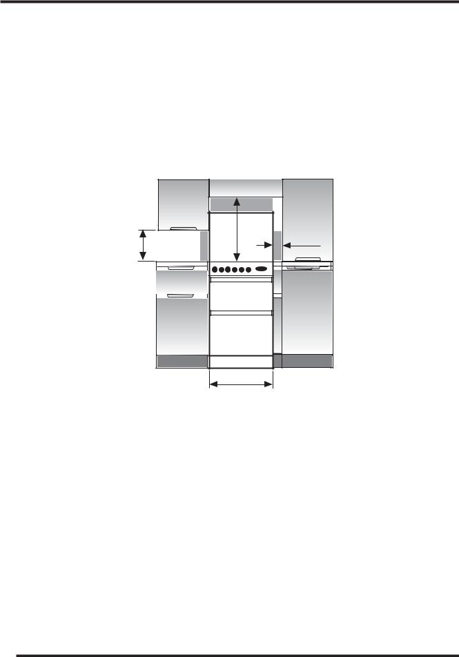
SPACE FOR FIXING
The cooker can be close fitted below hotplate level. This requires a minimum distance of 600mm between cupboard units of hotplate height.
When installing next to a tall cupboard, partition or wall, for a minimum distance of 400mm above hotplate level, allow a side clearance of at least 65mm.
The diagram below illustrates the minimum clearance between the cooker and adjacent walls, cupboards etc.
The wall behind the cooker, 50mm below and 450mm above, and the width of the cooker, must be a non-combustible material such as ceramic wall tiles.
If the cooker is to be fitted close to a corner on the left hand side, ensure that there is a clearance of at least 50mm to allow the main oven door to open fully for when removing oven shelves.
|
Min |
|
|
Min |
|
mmMin |
mm |
|
750mm |
|
|
|
840 |
65 mm Min |
|
|
|
400 |
|
|
|
600 mm Min |
|
COOKER HOODS
If a cooker hood is to be installed, refer to the cooker hood manufacturers’ instructions regarding fixing height.
PLEASE PHONE US TO REGISTER YOUR APPLIANCE AND ACTIVATE YOUR PARTS GUARANTEE ON 08448 24 24 24
8

INSTALLATION INSTRUCTIONS
UNPACKING THE COOKER
Unpack the components from inside the grill and oven. Check that the following parts are present:
Grill pan and grid |
Top oven/grill shelf heat shield |
Baking dish |
Pan supports |
Main oven shelves (2) |
Enamelled burner caps (4) |
Top oven/grill shelf (1) |
Literature |
Aluminium burner bodies (4) |
|
LEVELLING
Four skid feet are fitted which can be adjusted up or down to level the cooker.
CONVERSION FOR USE ON BUTANE (G30) OR PROPANE (G31)
Each burner requires the injector to be replaced and bypass screws adjusted or replaced as follows:
1.Remove the loose hotplate burner parts.
2.Using a 7mm socket, replace the hotplate injectors as appropriate (see table on previous page).
3.Re-position the loose burner parts.
4.Remove the enamelled baffle at the front of the grill (2 screws).
5.Remove the screw on the right hand side of the burner and gently slide the burner off the injector.
6.Using a 7mm socket, replace the grill injector as appropriate (see table on previous page).
7.Re-assemble the burner and baffle.
8.Inside the top oven, remove the central screw securing the burner retainer. Slide the retainer to the right slightly and lift away.
9.Lift the burner assembly and place on the floor of the oven to the right of the burner opening.
10.Using a 7mm socket, replace the oven injector as appropriate (see table on previous page). 11.Re-assemble the oven burner and retainer.
12.Replace the main oven injector following the same procedure as for the top oven.
13.From behind the cooker, remove the screws securing the rear panel and swing the left hand side outwards (viewed from the rear) to gain access to the main oven flame supervision device.
14.Replace the flame supervision device bypass screw.
15.Re-assemble the rear panel.
16.Carefully pull off the control knobs and timer buttons.
17.Remove the 2 screws securing the underside of the control panel. Slide the control panel to the left slightly to remove.
18.Remove the 6 screws securing the timer mounting panel. Without completely removing it, manoeuvre the timer mounting panel to gain access to the thermostat bypass screws.
19.Using a narrow flat bladed screwdriver rotate the bypass screws fully clockwise. The main oven thermostat bypass screw is located on the body of the thermostat below the spindle, the top oven thermostat bypass screw is located on the body of the thermostat to the right of the spindle and the hotplate tap bypass screws are located down the centre of the spindle.
20.Re-assemble the control panel parts.
21.Secure the self-adhesive LPG conversion label over the gas details on the data badge.
PLEASE PHONE US TO REGISTER YOUR APPLIANCE AND ACTIVATE YOUR PARTS GUARANTEE ON 08448 24 24 24
9
INSTALLATION INSTRUCTIONS
STABILITY CHAIN
A hole in the gas inlet valve bracket can be used to engage a stability chain.
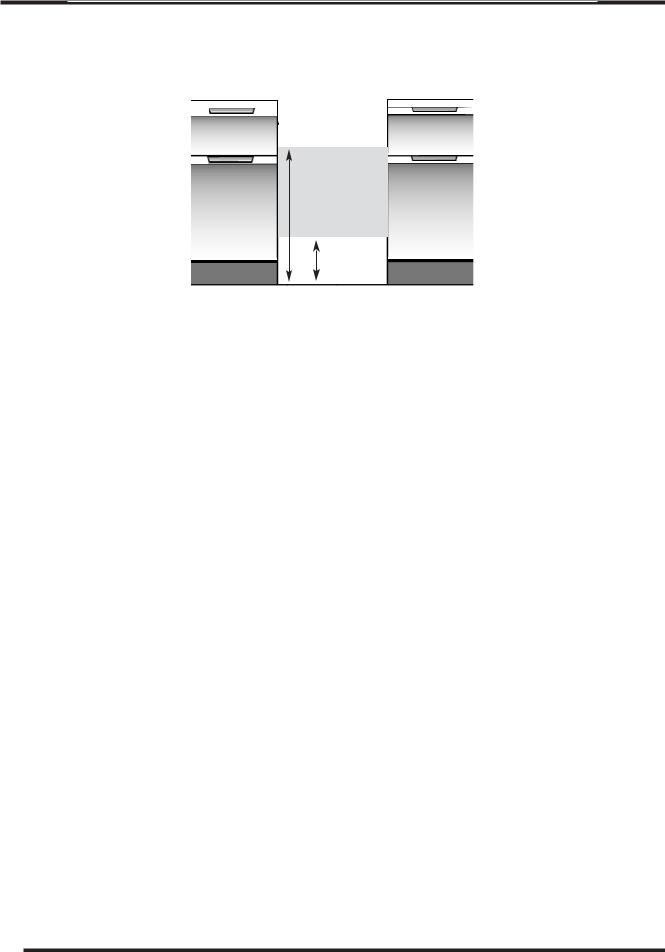
CONNECTING TO GAS SUPPLY
670
300
Connection to the cooker should be made with an approved appliance flexible connection to BS 669. A length of 0.9 to 1.25m is recommended. The length of hose chosen should be such that when the cooker is in situ, the hose does not touch the floor.
Those cookers converted to use on LPG should be connected with a hose suitable for LPG and capable of withstanding a pressure of 50 mbar.
An adaptor backplate should be fitted within the shaded area shown, to allow the cooker to be pushed fully to the wall and to ensure that the flexible hose is only likely to come into contact with areas at the rear of the cooker that do not exceed a temperature rise of 70°C.
PLEASE PHONE US TO REGISTER YOUR APPLIANCE AND ACTIVATE YOUR PARTS GUARANTEE ON 08448 24 24 24
10
ELECTRICAL CONNECTION
WARNING - THIS APPLIANCE MUST BE EARTHED. CONNECT TO A 230-240V A.C. SUPPLY ONLY.
Connection to the electricity supply should be made via a properly earthed, readily accessible wall socket which is adjacent to but not directly above, and not more than 1.25m away from the appliance and capable of electrical isolation.
The mains lead should be routed such that it cannot touch hot parts of the cooker i.e. the back panel above a height of 650mm from the floor.
Should this plug not fit the socket outlet in your home it should be cut off and replaced with a suitable plug as outlined below.
NOTE: The removed plug cannot be used for any other appliance and should therefore be properly disposed of and not left where children might find it and plug it into a supply socket - with the obvious consequent danger.
IF THE FITTED PLUG IS REMOVED
The flexible mains lead must be correctly connected as below to a three pin plug of not less than 13 amp capacity. If a B.S. 1363 fused plug is used, it must be fitted with a fuse which is approved to B.S. 1362.
IMPORTANT: The wires in the mains lead fitted to this appliance are coloured in accordance with the following code:
GREEN AND YELLOW |
- EARTH |
Yellow to |
|||
BLUE |
- NEUTRAL |
Green & |
|||
Earth |
|
||||
BROWN |
- LIVE |
|
|
|
|
to Live |
|||||
|
|
Brown |
|||
|
Blue to |
13 Amp |
|||
|
Neutral |
Fuse |
|||
|
Cord |
|
|
|
|
|
Clamp |
|
|
|
|
As the colours of the wires in the mains lead of this appliance may not correspond with the coloured markings identifying the terminals in your plug, proceed as follows:
The wire which is coloured green and yellow must be connected to the terminal in the plug which is marked with the
letter E or by the earth symbol  or coloured green or green and yellow.
The wire which is coloured blue must be connected to the terminal which is marked with the N or coloured black. The wire which is coloured brown must be connected to the terminal which is marked with the letter L or coloured red.
When wiring the plug, ensure that all strands of wire are securely retained in each terminal. Do not forget to tighten the mains lead clamp on the plug.
As the appliance must be earthed, do not use 2-pin sockets outlets, if you are in doubt, consult a qualified electrician.
Should the mains lead ever require replacement, it is essential that this operation be carried out by a qualified electrician and should only be replaced with a flexible cord of the same size i.e. 1.0mm2 cross sectional area PVC cable, available from our parts department (see Back Cover).
IF A MOULDED PLUG IS FITTED
In the event of replacing a fuse in the plug supplied an ASTA approved fuse to BS1362 must be fitted.
NOTE: The fuse cover must be refitted when changing the fuse. In the event of losing the fuse cover the plug must not be used until a replacement fuse cover has been obtained and fitted. A new fuse cover can be obtained from your local Electricity Board. The colour of the correct replacement fuse cover is that of the coloured marks or inserts in the base of the plug.
Make sure that the cable does not become trapped when pushing the cooker into position.
WARNING. If the electric supply fails to this appliance you must not use the grill or ovens.
PLEASE PHONE US TO REGISTER YOUR APPLIANCE AND ACTIVATE YOUR PARTS GUARANTEE ON 08448 24 24 24
11

INSTALLATION INSTRUCTIONS
INSTALLATION AND OPERATIONAL CHECKS
After installation, check for gas soundness. The supply pressure can be checked at the front left hotplate burner injector.
Fit the hotplate burner bodies and caps, pan supports and shelf shield(s). Referring to the instructions for use where necessary,
1.Check that the hotplate burners ignite and cross-light to all ports. Check for a steady flame on the low setting.
2.Check that the grill burner ignites and cross-lights to all ports and that the flames remain when the control is released 3 seconds later, Check for a steady flame on the low setting.
3.Check that with the main oven set to mark 9, the burner ignites and that tha flames remain when the control is released 3 seconds later. Leave the oven full on with the door closed for 10 minutes, and check that when the control is turned to mark 1 that the flame reduces.
4.Check that with the top oven set to mark 8, the burner ignites and that the flames remain when the control is released 3 seconds later. Leave the oven full on with the door closed for 10 minutes, and check that when the control is turned to mark 1 that the flame reduces.
5.Check the operation of the timer and oven light.
Instruct the user on operation of the cooker.
On those models adjusted for use with LPG, it is normal for the oven and grill burners to burn with yellow tips.
PLEASE PHONE US TO REGISTER YOUR APPLIANCE AND ACTIVATE YOUR PARTS GUARANTEE ON 08448 24 24 24
12
 Loading...