

Page 1

Instruction booklet
EN
English, 1
BFQ 700
DISHWASHER
Contents
Installation, 2-5
Positioning and levelling
Technical data
Electrical connection
Connecting the water supply
Description of the appliance, 6
Overall view
Control panel
Loading the racks, 7
Lower rack
Cutlery basket
Upper rack
Start-up and use, 8
Starting the dishwasher
Loading the detergent
Washing options
Wash cycles, 9
Wash cycle table
Rinse aid and refined salt, 10
Loading the rinse aid
Loading the refined salt
Care and maintenance, 11
Shutting off the water and electricity supplies
Cleaning the dishwasher
Preventing unpleasant odours
Cleaning the sprayer arms
Cleaning the filters
Leaving the machine unused for extended periods
Precautions and advice, 12-13
General safety
Disposal
Saving energy and respecting the environment
Troubleshooting, 14
Information for Test Labs, 15
After Sales Service, 16
After Sales Service
Essential Contact Information
Parts and Accessories
Appliance Registration
Hotpoint Guarantee, 17
Page 2
Installation
EN
Keep this instruction manual in a safe place for
future reference. If the appliance is sold, given away
or moved, please ensure the manual is kept with the
machine, so that the new owner may benefit from the
advice contained within it.
Please read this instruction manual carefully: it
contains important information regarding the safe
installation, use and maintenance of the appliance.
If the appliance must be moved at any time, keep it
in an upright position; if absolutely necessary, it may
be tilted onto its back.
Positioning and levelling
1. Remove the appliance from all packaging and
check that it has not been damaged during
transportation.
If it has been damaged, contact the retailer and do not
proceed any further with the installation process.
2. Check the dishwasher by placing it so that its sides
or back panel are in contact with the adjacent
cabinets or even with the wall. This appliance can also
be recessed under a single worktop (
Assembly instruction sheet
).
see the
Advice regarding the first wash cycle
After the appliance has been installed, immediately
before running the first wash cycle, completely fill
the salt dispenser with water and add approximately
2 kg of salt (
water may overflow: this is normal and is not a
cause for concern. It is also normal that the LOW
SALT* indicator light continues to flash for a few
cycles after the salt has been loaded.
see Rinse aid and refined salt
). The
Technical data
Dimensions
Capacity
Water supply
pressure
width 59.5 cm
height 82 cm
depth 57 cm
12 standard place-settings
30 Kpa ÷ 1Mpa (0.3 ÷ 10 bar)
4.3 psi – 145 psi
3. Position the dishwasher on a level and sturdy floor. If
the floor is uneven, the front feet of the appliance may
be adjusted until it reaches a horizontal position (the
angle of inclination must not exceed 2 degrees). If the
appliance is levelled correctly, it will be more stable
and much less likely to move or cause vibrations and
noise while it is operating.
4. Adjust the height of the rear feet from the front of
the appliance*: use a screwdriver to tighten or
loosen the screws on the lower part of the
dishwasher.
Anti-condensation strip*
After installing the dishwasher, open the door and
stick the adhesive transparent strip under the
wooden shelf in order to protect it from any
condensation that may form.
Power supply
voltage
Total absorbed
power
Fuse
See appliance data plate
See appliance data plate
See appliance data plate
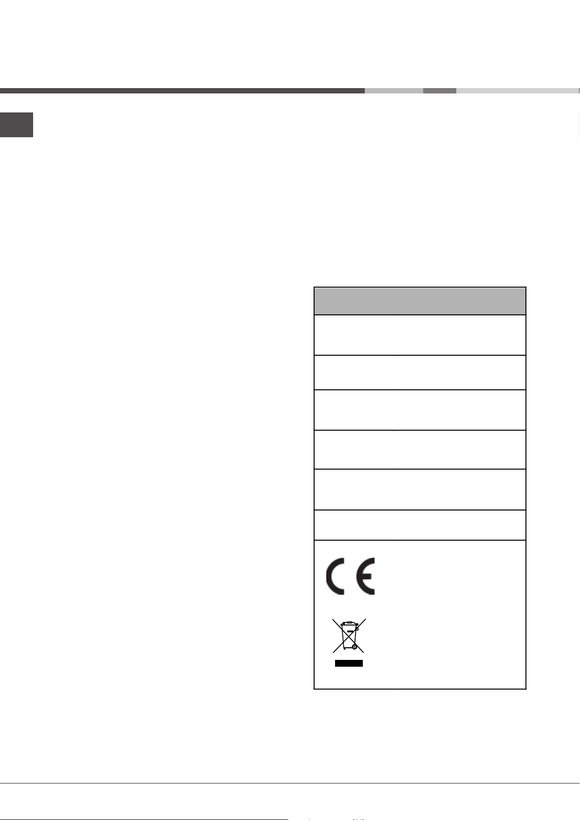
This dishwasher conforms to
the following European
Community Directives:
-73/23/EEC dated 19/02/73
(Low Voltage) and subsequent
modifications
-89/336/EEC dated 03/05/89
(Electromagnetic Compatibility)
and subsequent modifications
-97/17/EC (Labelling)
-2002/96/ CE
Waste
Electrical and Electronic
Equipment (WEEE)
* Only available in selected models.
2
Page 3

The dishwasher meets the requirements set out by
the regulations in force concerning safety and
electrical equipment.
Any technical checks should be conducted
exclusively by a trained and authorised technician:
Repairs carried out by unaithorised persons will
invalidate the guarantee, as well as posing a potential
hazard to the user.
The manufacturer declines all responsibility for
damage to persons or property resulting from failure to
observe the above precautions, from tampering with
even a single component or from the use of nonoriginal spare parts.
Electrical Connection
Before inserting the plug into the electrical socket,
make sure that:
• the socket is earthed and complies with current
regulations;
DO NOT use the plug unless the fuse cover is
fitted.
Changing the Plug
Cut off and dispose of the supplied plug if it does not
fit your socket.
To avoid a shock hazard DO NOT insert the
discarded plug into a socket anywhere else.
Wires in the mains lead are coloured accordance
with the following code:
Green/Yellow - Earth
Blue - Neutral
Brown - Live
If you change the plug, the colour of the wires in the
mains lead may not correspond with the terminal
markings in the plug, which if not coloured, could be:
EARTH ‘E’ or
NEUTRAL ‘N’
LIVE ‘L’
EN
• the socket can withstand the maximum load of the
appliance, which is indicated on the data plate
located on the inside of the door (
of the appliance
• the power supply voltage falls within the values
indicated on the data plate on the inside of the
door;
• the socket is compatible with the plug of the
appliance. If this is not the case, ask an authorised
technician to replace the plug (
not use extension cables or multiple sockets.
Once the appliance has been installed, the power
supply cable and the electrical socket should be
easily accessible.
The cable should not be bent or compressed.
The cable should be checked regularly and replaced
by authorised technicians only (
This appliance must be earthed.
);
see Description
see Assistance
see Assistance
); do
).
Changing the Mains Lead
A lead can be ordered from Hotpoint Service
UK: 08709 066 066 or
Republic of Ireland: 1850 302 220
- If you have damaged the existing lead or require a
longer one a charge will be made. It is strongly
advised that this work is carried out by a qualified
electrician.
- If the domestic wiring includes a residual currentoperated circuit breaker, ensure that it conforms to the
latest regulations.
The dishwasher must not be connected to the
electricity supply while installation is being carried out.
- This appliance should only be connected to a 230/
240V AC source, via a properly installed earthed
socket.
- Use the dishwasher solely in a domestic
environment.
- DO NOT stand or place heavy objects on the door
when it is open, this could damage the door or cause
the appliance to tip forward.
Fuses:your appliance comes fitted with a plug and a
13A fuse. If you need to replace the fuse, only those
rated at 13A and ASTA approved to BS1362 should be
used. If you lose the fuse cover, a replacement may
be obtained from your local authorised Service Centre
or Electrical company. Correct replacement is
identified by colour coding or the marking on base of
plug.
3
Page 4

EN
Connecting the water supplies
Connection to the water and electricity supplies
should only be performed by a qualified technician.
Ensure that the new hose supplied is connected
and the old hose is disposed of safely.
The dishwasher should not stand on top of the water
hoses or the electricity supply cable.
Connecting the water inlet hose
The water inlet (A) and outlet (B) hoses and the
electricity supply cable may be positioned towards the
right or the left in order to achieve the best possible
installation (
• To a suitable cold water connection point: before
attaching the hose, run the water until it is perfectly
clear so that any impurities that may be present in
the water do not clog the appliance; after
performing this operation, screw the inlet hose
tightly onto a tap with a ¾ gas threaded
connection.
• To a suitable hot water connection point: your
dishwasher may be provided with hot water from
the mains supply (if you have a central heating
system with radiators) provided that it does not
exceed a temperature of 60°C.
Screw the hose to the tap as described for
connection to a cold water supply.
see figure
).
Ensure the fill hose is only fitted to the cold water
supply. DO NOT overtighten the hose connector, hand
tight is sufficient.
Ensure the fill hose is not kinked.
Tap connections*: A range of adaptors are available
to suit your tap.
DO NOT connect the dishwasher to a single outlet
instantaneous water heater or an electric heater.
Standpipe
Ensure that the hose is not pushed too
far down the standpipe.
If the end of your drain hose is fitted with
‘retaining flaps*’, ensure they are
inserted fully into the standpipe. This
will prevent the pipe from jumping out
during installation and use.
DO NOT position the standpipe near an electrical
outlet.
ENSURE that the drain hose is not kinked and it is
routed as shown in the diagram.
The standpipe should have a bore of at least 38mm
(11/2”). It should be installed as shown, have a trap
fitted and must discharge into the same drain system
as your household sink.
It MUST NOT be connected to a surface water drain.
If the inlet hose is not long enough, contact a
specialist store or an authorised technician (
Assistance
The water pressure must be within the values
indicated in the Technical data table (
The hose should not be bent or compressed.
4
).
see
see Installation
).
* Only available in selected models.
Page 5
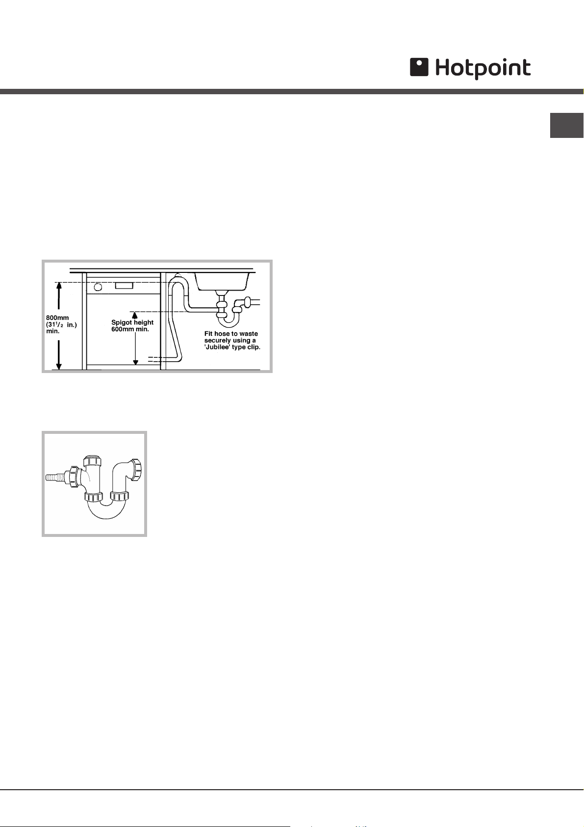
Sink Waste System
For under sink drainage:
Anti-flooding protection*
EN
To ensure floods do not occur, the dishwasher:
• before connecting the drain hose, remove any
internal restrictions; this will prevent a build up of
debris which could cause a blockage
• remove any restrictions from the waste spigot and
ensure that the sealing bung is removed
• the hose should be routed, such that it is raised
to a minimum height of 800mm (31/2”).
Ensure the sink outlet pipe has a minimum diamtere
of 32mm.
• Untie the end of the
GREY drainage hose from
the rear of the appliance.
- is provided with a special system which blocks the
water supply in the event of anomalies or leaks from
inside the appliance.
- is provided with a
words it has a water inlet hose that consists of a
transparent hose on the outside and a red hose on the
inside: both the hoses can withstand extremely high
pressure. If the internal hose breaks, the external hose
becomes a bright red colour and carries the water
instead, thus avoiding any leakage.
It is very important to check the external hose
regularly: if it is a bright red colour, it must be replaced
by an authorised technician as soon as possible (
Assistance
).
Water Stop
* safety device, in other
see
• Reposition the ‘Hooked
End Support’ as required
along the GREY drainage
hose.
• If fitting an under sink waste disposal unit, cut out
the membrane, bung or blanking plug.
Ensure the drain hose is securely attached, to
prevent it coming away while the machine is in use
and causing a flood.
* Only available in selected models.
5
Page 6

Description of the appliance
EN
Overall view
1
4
6
9
11
7
10
1. Upper rack
2. Upper sprayer arm
3. Tip-up compartments
4. Rack height adjuster
5. Lower rack
3
2
6. Lower sprayer arm
7. Cutlery basket
8. Washing filter
9. Salt dispenser
10. Detergent and rinse aid dispensers
11. Data plate
5
8
Control panel
WASH CYCLE SELECT
WASH CYCLE
indicator lights
button
LOW SALT
indicator light*
LOW RINSE AID
indicator light*
EXTRA DRYING
button*
HALF LOAD ON
UPPER RACK
indicator light*
HALF LOAD ON
LOWER RACK
indicator light*
DELAYED START
button*
HALF LOAD
button*
4h
1
2
2h
6h
DELAYED
START
indicator light*
ON/OFF
button
ON/OFF
indicator light
* Only available in selected models.
6
Page 7

Loading the racks
! Before loading the rack, remove all food residue from the
crockery, leave saucepans and frying pans with burnt-on
residue to soak and empty all remaining liquid from cups and
glasses. After loading the appliance, check that the sprayer
arms can rotate freely.
Lower rack
Arrange the more difficult items to wash using the
examples
needed.
• Serving dishes and lids: place these at the sides of the
• Saucepans and salad bowls: always turn these upside
• Very deep dishes: position these at an angle.
In order to guarantee the best washing and drying
performance, the surface of the lower rack is more uneven
than that of the upper rack.
as a guide and use the collapsible supports* where
rack.
down.
Loading
Cutlery basket
The type of cutlery basket may vary according to the
dishwasher model.
Knives and other sharp utensils should be placed in the
cutlery basket with the point facing downwards.
If the rack is equipped with the click
clack handles* (
them upwards or downwards to
adjust the height.
see figure
Loading examples for the upper rack
Loading examples for the lower rack
EN
), pull
To divide the central basket* into two separate pieces: pull out
the handle. The two detachable side compartments* may be
hooked onto the upper or lower rack.
The two grids* may be positioned in the basket to separate
the cutlery: place the pieces of cutlery into the appropriate
compartments with the handles at the bottom.
Upper rack
Load this rack with delicate and lightweight crockery: glasses,
tea and coffee cups, saucers, small salad bowls, saucepans
and small saucepans that are not too soiled, using the
examples
• Lightweight crockery: position these dishes so that they
• Mugs and cups: place these on the tip-up
• Long sharp knives and serving utensils: place these on
as a guide.
will not be moved by the jets of water.
compartments**.
the tip-up compartments**.
Adjusting the height of the upper rack
In order to make it easier to arrange
the crockery, the upper rack may be
1
3
moved to a higher or lower level.
2
Open the left and right guide rail
stops and pull out the rack; position
it higher or lower as required, slide it
along the guide rails until the front
4
wheels are in place and close the
stops (
see figure
).
Loading
Baby Tip-up compartments
**
For dishwasher models with a
Baby Cycle, tip-up
compartments which are
suitable for washing bottles,
rings and teats are provided
(and have their own instruction
sheet).
Items that should not be washed in the dishwasher
• Wooden items, objects with wooden or horn handles or
glued-on parts.
• Items made from aluminium, copper, brass, pewter or tin.
• Items made from plastic that is not heat-resistant.
• Antique or hand-painted porcelain.
• Antique silver. Silver that is not antique may, however, be
washed in the dishwasher using a delicate wash cycle,
provided that it does not come into contact with other
metals.
When buying crockery and cutlery we recommend that you
check whether it can be washed using the dishwasher.
Washing the handles*
To wash the upper and lower rack handles: remove the two
fastening plugs, lift out the handles and rinse them under
running water, then fasten them to the rack using the same
plugs.
* Only available in selected models.
** The number and position may vary.
7
Page 8

A
B
D
C
Start-up and use
EN
1. Turn the water tap on.
2. Open the door and press the ON/OFF button: the
indicator light will illuminate.
3. Measure out the detergent (see below).
4. Load the racks (see Loading the racks).
5. Select the programme by pressing the WASH
CYCLE SELECT button; the corresponding indicator
light will illuminate.
6. Select the wash options (see below).
7. Start the wash cycle by shutting the door: the
machine will emit a confirmation beep.
8. At the end of the cycle two short beeps will sound
and the WASH CYCLE indicator light will flash. Open
the door, switch off the appliance by pressing the
ON/OFF button, shut off the water tap and unplug
the appliance from the electricity socket.
9. Wait for a few minutes before removing the
crockery, in order to avoid burns. Unload the racks,
beginning with the lower level.
Modifying a wash cycle in progress
If a mistake was made during the wash cycle
selection process it is possible to change the cycle,
provided that it has only just begun: open the door,
taking care to avoid the escaping steam, and press
the WASH CYCLE SELECT button, holding it for 4
seconds. After one long beep and three short
beeps, the WASH CYCLE indicator light will switch
off: select the new wash cycle and start the
programme by shutting the door.
Adding extra crockery
Open the door, taking care to avoid the escaping
steam, and place the crockery inside the
dishwasher. Close the door: the cycle starts from the
point at which it was interrupted.
Accidental interruptions
If the door is opened during the wash cycle, or if
there is a power cut, the cycle stops. It starts again
from the point at which it was interrupted once the
door has been shut or the electricity supply is
restored.
Loading the detergent
A successful wash also depends on the correct
amount of detergent being used, as recommended
by the manufacturer. Exceeding the recommended
amount does not result in a more effective wash and
pollutes the environment.
comparcompar
compar
comparcompar
comparcompar
compar
comparcompar
1. Open cover C by pressing button D.
2. Pour in the detergent after consulting the
cycle table
tment Atment A
tment A: Washing detergent
tment Atment A
tment Btment B
tment B: Pre-wash detergent
tment Btment B
:
second tablet at the bottom of the appliance.
3. Remove detergent residues from the edges of the
compartment and close the cover until it clicks.
Washing options
Delayed start
It is possible to delay the start time of the cycle by
2, 4 or 6 hours.
1. Press the DELAYED START button: every time the
button is pressed, a beep is emitted and the
selected delayed start indicator light illuminates.
2. Select the wash cycle and shut the door: after the
beep sounds, the timer begins counting down.
3. Once this time has elapsed, the indicator light
switches off and the wash cycle begins.
To adjust the delay time and select a smaller period
of time, press the DELAYED START button. To
cancel it, press the button repeatedly until the
selected delayed start indicator light switches off.
The wash cycle will start automatically as soon as
the door is shut.
Half load using the upper or lower rack*
If there are not many dishes to be washed, a half
load cycle may be used in order to save water,
electricity and detergent. Before selecting the wash
cycle press the HALF LOAD button repeatedly: the
indicator light will illuminate and the wash cycle will
take place only in the upper or the lower rack.
Remember to load the upper or lower rack only, and
to reduce the amount of detergent accordingly.
It is better to use powder detergent in this case.
Extra drying*
To make sure that the crockery is completely dry at
the end of the cycle, press the EXTRA DRYING
button before selecting the wash cycle. A prolonged
beep will sound to indicate that this option has been
selected and a short beep will sound to indicate
when it has been deselected.
This option is incompatible with the soak cycle.
If the Extra drying option is selected, the wash
cycles will last longer.
Wash
* Only available in selected models.
Starting the dishwasher
• for powder detergent
use compartments A and
B
• for tablets, use
compartment A and the
bottom of the appliance,
i.e. when the cycle
requires 1 tablet, place it
in compartment A and
close the cover; when it
requires 2, place the
8
Page 9

Wash cycles
Wash cycle table
Ariston dishwashers are fitted with an automatic filter cleaning system that may increase the cycle duration.
AUTO WASH CYCLES: This model of dishwasher is equipped with a special sensor which can be used to
assess the level of soiling and automatically select the most efficient and economic wash cycle accordingly.
The duration of the auto wash cycles may vary due to the operation of the sensor.
Wash cycle selection
instructions
Extremely soiled dishes
and pans (not to be
used for delicate items).
Normally soiled pans
and dishes. Standard
daily wash cycle.
Wash cycle
Super Wash
Normal
Detergent
(A) = compartment A
(B) = compartment B
Powder Liquid Tablets
1 (A)
30 g (A)
5 g (B)
30 g (A) 30 ml (A) 1 (A)
30 ml (A)
5 ml (B)
1 (bottom of
the
appliance)
Pre-wash Drying
•
• • 100’
•
Wash cycle
duration
(tolerance
±10%)
120'
EN
Preliminary wash cycle
for dishes while the load
is awaiting completion
with the dishes from the
next meal.
Environmentally-friendly
wash cycle with low
energy consumption
levels, suitable for pans
and dishes.
Economic and fast
wash cycle to be used
for lightly soiled dishes.
(Run cycle immediately
after use.)
Disinfecting wash cycle
suitable for washing
bottles, rings and teats
together with plates,
cups, glasses and
cutlery. Load the items
on the upper rack.
Wash differentiated on
the two racks delicate
for glassware and
glasses on the upper
rack and heavy duty for
the pans on the lower
rack. Duo Wash
Soak
Eco
Rapid
Baby Care
12'
25 g (A)
5 g (B)
25 g (A) 25 ml (A) 30’
20 g (A) 20 ml (A)
25 g (A)
5 g (B)
25 ml (A)
5 ml (B)
25 ml (A)
5 ml (B)
1 (A)
1 (A)
•
•
•
•
145'
60'
108’
Note
To make it easier to measure out the detergent, it is worth remembering that:
1 tablespoon = 15 grams of powder = approximately 15 ml of liquid
1 teaspoon = 5 grams of powder = approximately 5 ml of liquid
9
Page 10

Rinse aid and refined salt
EN
Only use products that have been specifically
designed for dishwashers.
Do not use table salt or industrial salt.
If using a multi-functional product (2-in-1, 3-in-1, 4-in-1,
etc.) it is not necessary to add rinse aid; however,
we recommend that you add salt, especially if you
live in an area where the water is hard or very hard. If
you do not add salt or rinse aid, the LOW SALT* and
LOW RINSE AID* indicator lights will flash
continuously.
Loading the rinse aid
Rinse aid makes it easier for the crockery to dry, as
water runs off surfaces more readily and therefore
does not leave streaks or marks.
The rinse aid dispenser should be filled:
• whenever the indicator light (H) signals that it is
empty. Illuminated light: add rinse aid; unlit light:
there is no shortage of rinse aid in the dispenser.
• when the LOW RINSE AID* indicator light on the
panel flashes;
H
3. Screw the lid back on.
Adjusting the amount of rinse aid
If you are not completely satisfied with the washing or
drying results, you may adjust the quantity of rinse aid
used. Use a screwdriver to turn the dosage adjuster to
one of the 6 pre-set positions (the default position is
set to 4):
• if there are white streaks on the crockery, set the
adjuster to a lower number (1-3).
• if drops of water remain on the crockery or there
are limescale marks present after the cycle has
finished, set the adjuster to a higher number (4-6).
If you are using multi-functional tablets (2-in-1, 3-in-1,
4-in-1, etc.) and you wish to further improve the
drying performance of the appliance, fill the
dispenser and set the dosage adjuster to 2.
1. Open the dispenser by
turning the lid (G) in an
anticlockwise direction.
2. Pour in the rinse aid,
making sure it does not
F
overflow from the
dispenser. If this happens,
G
clean the spill immediately
with a sponge.
• when the green float* cannot be seen by simply
looking at the cap of the salt dispenser;
• when the LOW SALT* indicator light on the panel
flashes;
• if your machine is not equipped with an indicator
light or a green float:
approximately every 30 wash cycles;
1. Remove the lower rack and
unscrew the cap of the
dispenser (in an anticlockwise direction).
2. For the first wash cycle only:
fill the dispenser up to the
edges with water.
3. Position the funnel provided
correctly (
the edges (approximately 2 kg); it is normal for a
little water to leak out.
4. Remove the funnel, wipe away any salt residue
from the thread and screw the cap on tightly, so that
detergent does not leak into the dispenser during the
wash cycle (this could damage the water softening
system beyond repair).
When salt has been added, run a wash cycle
immediately, without crockery, in order to remove any
salt solution that has leaked out and to avoid
corrosion.
Adjusting the amount of salt*
It is possible to adjust the amount of salt used
according to the hardness of the water in your area
(this information is available from your local water
board).
1. Unscrew the dispenser cap.
2. Turn the arrow on the neck of the dispenser (
figure
below as a guide.
see figure
) towards the + or - symbols, using the table
) and fill the salt dispenser up to
see
Loading the refined salt
In order to obtain the best possible results from a
wash cycle, make sure that the dispenser is never
empty. Refined salt removes limescale from the water,
thus avoiding the formation of deposits on crockery.
The salt dispenser is located in the lower part of the
dishwasher (
10
see Description
) and should be filled:
The default setting of the water softening system is +.
If using multi-functional tablets (2-in-1, 3-in-1, 4-in-1,
etc.) fill the salt dispenser and set the adjuster to -; if
the hardness of the water is greater than 60°fH, set it
to +.
* Only available in selected models.
Page 11

Care and maintenance
Shutting off the water and electricity
supplies
• Turn off the water tap after every wash cycle to
avoid leaks.
• Remove the plug from the socket when cleaning
the machine and when carrying out maintenance
work.
Cleaning the dishwasher
• The external surfaces of the machine and the
control panel may be cleaned using a cloth
dampened with warm soapy water. Do not use
solvents or abrasive products.
• Any marks on the appliance interior may be
removed using a cloth dampened with water and a
little vinegar.
Preventing unpleasant odours
• Always keep the door of the appliance ajar in order
to avoid moisture from forming and being trapped
inside the machine.
• Clean the seals around the door and detergent
dispensers regularly using a damp sponge. This
will avoid food becoming trapped in the seals,
which is the main cause of the formation of
unpleasant odours.
Cleaning the sprayer arms
Food residue may
become encrusted onto
the sprayer arms and
block the holes used to
spray the water. It is
therefore recommended
that the arms are
checked from time to
time and cleaned with a
small non-metallic
brush.
Cleaning the filters
The filters remove food residue from the water used in
the wash cycle: to obtain the best results from each
wash, they should be cleaned.
Clean the filters regularly.
After cleaning check that the filter assembly has
been replaced correctly.
The dishwasher should not be used without filters.
1. Remove the filters by pulling the handle upwards.
2. Clean the filters:
• after every wash
cycle, remove the
C
1
2
A
B
B
C
A
Use a small non-metallic brush to clean these parts.
3. Reconstruct the filter assembly and replace it in the
correct position, following movements 1 and 2 as
shown in the figure, until it clicks into place.
largest pieces of
residue from
semicircular plate A and
glass B (these may be
removed by pulling the
handle) by rinsing them
under running water.
• The entire filter
assembly should be
cleaned thoroughly
once a month: this
includes the
semicircular plate A,
the glass B and the
cylinder C (this may
be removed by
turning it in an anticlockwise direction).
Leaving the machine unused for
extended periods
• Run a wash cycle when the dishwasher is empty.
EN
• Unplug the appliance and disconnect the water
supply.
• Leave the door of the appliance ajar.
11
Page 12

Precautions and advice
EN
The appliance was designed and manufactured in
compliance with current international safety
standards. The following information has been
provided for safety reasons and should therefore be
read carefully.
General safety
• The appliance was designed for domestic use
inside the home and is not intended for commercial
or industrial use.
• The appliance must be used by adults only, to
wash domestic crockery according to the
instructions in this manual.
• The appliance must not be installed outdoors, even
in covered areas. It is extremely dangerous to
leave the machine exposed to rain and storms.
• Do not touch the appliance when barefoot.
• When unplugging the appliance always pull the
plug from the mains socket, do not pull on the
cable.
• The water supply tap must be shut off and the plug
should be removed from the electrical socket
before cleaning the appliance or carrying out any
maintenance work.
• If the appliance breaks down, do not under any
circumstances touch the internal parts in an
attempt to carry out the repair work yourself.
• Never touch the heating element.
• Do not lean or sit on the open door of the
appliance: this may cause the appliance to
overturn.
• The packaging material should not be used as a
toy: it can become a choking or suffocation
hazard.
If your family includes children:
• DO NOT allow children to play with the appliance or
tamper with its controls.
• Keep detergents and rinse aids away from children.
• Keep children away from the open door of a
dishwasher, there could still be some detergent left
inside.
Disposal of old electrical appliances
The European Directive 2002/96/EC on Waste
Electrical and Electronic Equipment (WEEE), requires
that old household electrical appliances must not be
disposed of in the normal unsorted municipal waste
stream. Old appliances must be collected separately
in order to optimise the recovery and recycling of the
materials they contain and reduce the impact on
human health and the environment. The crossed out
"wheeled bin" symbol on the product reminds you of
your obligation, that when you dispose of the
appliance it must be separately collected.
Consumers should contact their local authority or
retailer for information concerning the correct disposal
of their old appliance.
Saving energy and respecting the
environment
Saving water and energy
• Only start a wash cycle when the dishwasher is
full. While waiting for the dishwasher to be filled,
prevent unpleasant odours with the Soak cycle
see Wash Cycles
(
• Select a wash cycle that is suited to the type of
crockery and to the soil level of the crockery using
Wash cycle table
the
- for dishes with a normal soil level, use the Eco
wash cycle, which guarantees low energy and
water consumption levels.
- if the load is smaller than usual activate the Half
load option (
• If your electricity supply contract gives details of
electricity saving time bands, run wash cycles
during the periods when a lower tariff is applied.
The Delayed start* button (
helps you organise the wash cycles accordingly.
).
:
see Start-up and use
see Start-up and use
).
)
12
Page 13

Phosphate-free and chlorine-free detergents
containing enzymes
• We strongly recommend that you use detergents
that do not contain phosphates or chlorine, as
these products are harmful to the environment.
• Enzymes provide a particularly effective action at
temperatures around 50°C, and as a result
detergents containing enzymes can be used in
conjunction with low-temperature wash cycles in
order to achieve the same results as a normal 65°C
wash cycle.
• To avoid wasting detergent, use the product in
appropriate quantities based on the manufacturer’s
recommendations, the hardness of the water and
the soil level and quantity of the crockery. Even if
they are biodegradable, detergents contain
substances that may alter the balance of nature.
Recycling & Disposal Information
As part of Hotpoint's continued commitment to helping
the environment, Hotpoint reserves the right to use
quality recycled components to keep down customer
costs and minimise material wastage.
Please dispose of packaging and old appliances
carefully.
To minimise risk of injury to children, remove the door,
plug and cut mains cable off flush with the appliance.
Dispose of these parts separately to ensure that the
appliance can no longer be plugged into a mains
socket and the door cannot be locked shut.
EN
* Only available in selected models.
13
Page 14

Troubleshooting
EN
Whenever the appliance fails to work, check for a solution from the following list before calling for Assistance
see Assistance
(
).
Malfunction: Possible causes / Solutions:
The dishwasher does not start.
No water enters the dishwasher.
No water drains out from the
dishwasher.
The dishwasher makes
excessive noise.
The dishes and glasses are
covered in a white film or
limescale deposits.
The dishes and glasses are
streaked or have a bluish
tinge.
The crockery has not been dried
properly.
The dishes are not clean.
Tap shut-off alarm.
(several short beeps are emitted)
(the second and third WASH
CYCLE indicator lights flash,
beginning from the right).
Clogged filter alarm
(the second and fourth WASH
CYCLE indicator lights flash,
beginning from the right).
Water loading solenoid
valve malfunction alarm
(the third WASH CYCLE indicator
light flashes, beginning from the
right).
The plug has not been inserted into the electrical socket
properly, or there is no power in the house.
The dishwasher door has not been shut properly.
A delayed start has been programmed (see Start-up and use).
There is no water in the mains supply.
The water inlet hose is bent (see Installation).
The dishwasher cycle has not yet finished.
The water outlet hose is bent (see Installation).
The drain duct is blocked.
The filter is clogged up with food residues.
The dishes are rattling against each other or against the
sprayer arms.
The level of the refined salt is low or the dosage setting is not
suited to the hardness of the water (see Rinse aid and salt).
The lid on the salt dispenser is not closed properly.
The rinse aid has been used up or the dosage is too low.
The crockery is made from non-stick material.
The rinse aid dosage is too high.
The rinse aid has been used up or the dosage is too low (see
Rinse aid and salt).
The rinse aid dispenser setting is not high enough.
A wash cycle without a drying programme has been selected.
The racks are overloaded (see Loading the racks).
The crockery has not been arranged well.
The sprayer arms cannot move freely.
The wash cycle is too gentle (see Wash cycles).
The detergent has not been measured out correctly or it is not
suited to the type of wash cycle (see Start-up and use).
The filter is dirty or blocked (see Care and maintenance).
The refined salt level is low (see Rinse aid and salt).
Turn on the tap and the appliance will start after a few
minutes.
The appliance lock has been activated because no action was
taken when the beeps sounded. Switch off the machine using
the ON/OFF button, turn on the tap and switch the machine
back on after 20 seconds by pressing the same button. Re-
programme the machine and restart the wash cycle.
Switch off the machine by pressing the ON/OFF button and
clean the filters (see Maintenance), then switch the
dishwasher back on by pressing the same button. Re-
programme the machine and restart the wash cycle.
Switch off the appliance by pressing the ON/OFF button and
switch it back on after a minute. If the alarm continues, shut
off the water tap to eliminate the risk of flooding, remove the
plug from the electrical socket and call Assistance.
14
Page 15

Information for test labs
Load for 12 Standard Settings tests
lower basket
9
1
A
D
B
12
C
3
A
10
upper basket (at top position)
2
C
i
f
EN
Lower basket Upper basket
Type Item Diameter Volum
soupe plate 23 cm.
A
dinner plate 26 cm.
B
dessert
C
oval platter 32 cm.
D
(approximately)
19 cm.
plate
2
Type Item Diameter/Volum
e
serving
f
g
saucer 14 cm.
h
serving
k
serving
i
(approximately)
cup 0,20 l.
19 cm.
bowl
glass 250 ml.
13 cm.
bowl
16 cm.
bowl
Loading the detergent
• The cleaning detergent should be introduced into
the two containers “Comp.2” and “Comp.3” (
table at the end of the page
Comp.2
).
Comp.3
see
e
k
e
g
e
h
g
Loading the Rinse Aid
5
5
6
12 6
• The amount of rinse aid used for each cycle can
be regulated by turning the dose adjuster ‘F’ which
you will find under lid ‘C’.There are 6 different
Loading the Basket
settings; the normal dosage is setting 5.
F
7
8
2
3
1
64
5
• This basket is
equipped with
5
5
5
5
5
55555
two removable
grids: insert the
5
3
7
8
4
2
2
3
3
3
3
3
1
1
1
4
4
4
4
4
2
22
2
3
3
3
1
1
11
1
4
4
2
5
3
3
3
7
1
1
1
1
6
4
4
4
4
2
2
2
2
2
cutlery one by
one into the
slots, with the
handles at the
bottom.
• Position them so
that they don't
touch.
EN 50242
IEC/DIN
C
Cycle Total Detergent Comp.2 Comp.3
Eco 30 gr 25 5
Eco+extra dry
♦
30 gr 30
Press the EXTRA DRY BUTTON*
door side
* Only available in selected models.
15
Page 16

After Sales Service
EN
After Sales Service
No one is better placed to care for your Hotpoint
appliance during the course of its working life
than us - the manufacturer.
Essential Contact Information
Hotpoint Service
We are the largest service team in Europe offering
you access to 400 skilled telephone advisors and
1100 fully qualified engineers on call to ensure you
receive fast, reliable, local service.
UK: 08709 066 066
Republic of Ireland: 0818 313 413
www.hotpointservice.co.uk
Please note: Our advisors will require the following
information:
Model number:
Appliance Registration
We want to give you additional benefits of Hotpoint
ownership. To activate your free 5 year parts
guarantee you must register your appliance with us.
UK: 0870 6092094
Republic of Ireland: 01 230 0800
www.hotpointservice.co.uk
Indesit Company UK Ltd. Morley Way,
Peterborough, PE2 9JB
Indesit Company Unit 49 Airways Industrial
Estate,Dublin 17
Serial number:
Parts and Accessories
We supply a full range of genuine replacement parts
as well as accessory products that protect and
hygienically clean your appliance to keep it looking
good and functioning efficiently throughout its life.
UK: 08709 077 077
Republic of Ireland: 0818 313 413
www.hotpointservice.co.uk
16
Page 17

Guarantee
12 Months Parts and Labour Guarantee
Your appliance has the benefit of our manufacturer’s
guarantee, which covers the cost of breakdown
repairs for twelve months from the date of purchase.
This gives you the reassurance that if, within that
time, your appliance is proven to be defective
because of either workmanship or materials, we will,
at our discretion, either repair or replace the
appliance at no cost to you.
Guarantee terms and conditions
This guarantee is subject to the following conditions:
-
The appliance has been installed and operated
correctly and in accordance with our
operating and maintenance instructions.
-
The appliance is used only on the electricity or gas
supply printed on the rating plate.
-
The appliance has been used for normal domestic
purposes only.
-
The appliance has not been altered, serviced,
maintained, dismantled, or otherwise
interfered with by any person not authorised by us.
The guarantee does not cover:
-
Damage resulting from transportation, improper
use, neglect or interference or as a result of
improper installation.
-
Replacement of any consumable item or
accessory.These include but are not limited to:
plugs,cables, batteries, light bulbs, fluorescent
tubes and starters, covers and filters.
-
Replacement of any removable parts made of
glass or plastic.
5 Year Parts Guarantee
Hotpoint also offers you a free 5 year parts
guarantee. This additional guarantee is conditional
on you registering your appliance with us and the
parts being fitted by one of our authorised
engineers. There will be a charge for our engineer's
time. To activate the extra parts warranty on your
appliance, simply call our registration line on 0870
6092094 (ROI 01 230 0800).
Extended Guarantees
We offer a selection of repair protection plans that
enable you to fully cover yourself against the
expense of repair bills for the life of your policy. To
find the ideal plan for you please call our advice line
on 08709 088 088 (ROI 01 230 0233).
Free Helpdesk Service
We have a dedicated team who can provide free
advice and assistance with your appliance if you
experience any technical difficulties within the first
90 days of ownership. Simply call our Hotpoint
Service Hotline on 08709 066 066 (ROI 0818 313
413) for telephone assistance, or, where necessary,
to arrange for an engineer to call. If we cannot
resolve the technical problem we will replace your
machine or, if you prefer, give you your money back.
EN
THIS GUARANTEE WILL NOT APPLY IF THE
APPLIANCE HAS BEEN USED IN COMMERCIAL
OR NON-DOMESTIC PREMISES.
17
Page 18

EN
Notes
18
Page 19

Notes
EN
19
Page 20

EN
195055348.01
pb-04/2006- Xerox Business
Services
Retention of this Instruction Book
This Instruction Book must be kept handy for reference as it contains important details on the safe and proper use of the
appliance.
If you sell or pass the appliance to someone else, or move house and leave it behind, make sure this Book is also provided so the
new owner can become familiar with the appliance and safety warnings.
If the Book is lost or damaged a copy may be obtained from:
Indesit Company UK Ltd. Morley Way, Peterborough, PE2 9JB
www.hotpointservice.co.uk
20
 Loading...