

Page 1

For use with the following list numbers:
2507-04 2507-18 2507-29 2507-46
2507-13 2507-22 2507-36 2507-54
2507-15 2507-27 2507-42 2507-88
Technical Service Manual
430-03714-005
Page 2

SECTION
© Hospira, Inc.
This document and the subject matter disclosed herein are proprietary information. Hospira retains
all the exclusive rights of dissemination, reproduction, manufacture, and sale. Any party using this
document accepts it in confidence, and agrees not to duplicate it in whole or in part nor disclose it
to others without the written consent of Hospira.
®
430-03714-005 LifeCare
5000 Series
Page 3

Change History
Part Number Description of Change
430-03714-001 (Rev. 4/92) Original issue
430-03714-A01 (Rev. 1/93) Revised part number
and title
Section 1.1: Deleted
obsoleted information
pertaining to Level 1 and
Level 2 repairs
Section 2: Revised
warranty
Section 7: Deleted
obsolete information
pertaining to servicing
qualifications
Section 7.2.1: Correct
battery pack and
minipole assembly part
numbers
430-03714-002 (Rev. 1/93) Second Issue
Remove
and Destroy
Pages
All pages All pages
Insert
Change
Pages
430-03714-A02 (Rev. 4/93) Updated cover and
added copyright
information to the
reverse side
Updated Change History i, ii i, ii
Updated Contents iii to x iii to x
Added Section 1.2,
Conventions
Section 1.6.1: Removed
Table 1-4
430-03714-B02 (Rev. 12/93) Not Issued
430-03714-C02 (Rev. 1/94) Updated cover and
copyright
Updated Change History i, ii i, ii
Updated Contents iii to x iii to x
Updated Table 5-1,
Cleaning Solutions
cover cover
1-3 to 1-4 1-3 to 1-4
1-5 to 1-10 1-5 to 1-8
cover and
copyright
page
5-1, 5-2 5-1, 5-2
cover and
copyright
page
Updated Section 5.2,
Performance Verification
Test (1.5 Series)
Technical Service Manual i 430-03714-005
5-3 to 5-6 5-3 to 5-6
Page 4

SECTION
Part Number Description of Change
Updated Section 5.2.9,
Bubble Sensor Location
Test
Updated Section 5.3,
Performance Verification
Test (1.6 Series)
Updated Section 5.3.7,
Bubble Sensor Location
Test
Updated Section 6.2,
Audible Alarms, Table
6-1, Alarm Codes and
Corrective Actions
Updated Section 7.2,
Repair and Replacement,
Section 7.2.1.2,
Materials
Removed reference to
"white lithium" grease:
Sections 7.2.7; 7.2.7.2;
7.2.23; 7.2.23.2;
7.2.23.3; 7.2.23.4
Remove
and Destroy
Pages
Insert
Change
Pages
5-9, 5-10 5-9, 5-10
5-13 to 5-16 5-13 to 5-16
5-17, 5-18 5-17, 5-18
6-9 to 6-12 6-9 to 6-12
7-3, 7-4 7-3, 7-4
7-9 to 7-12
7-29 to 7-36
7-9 to 7-12
7-29 to 7-36
Added Section 7.2.29,
Plunger Motor Shaft
Lubrication, and Figure
7-14, Plunger Motor
Shaft Lubrication Points
Updated back cover Back cover Back cover
430-03714-003 (Rev. 8/94) Third issue
430-03714-A03 (Rev. 3/95) Updated Cover and
Copyright
Updated Change History
and Contents
Updated Section 1.1 1-3, 1-4 1-3, 1-4
Updated Section 1.6 1-7 to 1-10 1-7 to 1-10
Updated Section 4.1.2.1 4-3, 4-4 4-3, 4-4
Updated Section 4.8 4-19, 4-20 4-19, 4-20
Updated Table 5-1,
reordered Sections 5.2
and 5.3, and updated
Section 5.5
7-41 to 7-44 7-41 to 7-44
Cover and
Copyright
Cover and
Copyright
iii to x iii to x
5-1 to 5-28 5-1 to 5-26
430-03714-005 ii LifeCare
®
5000 Series
Page 5

Part Number Description of Change
Updated Table 6-1,
alarm code 24
Added Tables 6-3 and
6-4
Updated Sections 7.2,
7.2.1.1 and 7.2.1.2
Updated Figure 7-6 7-19, 7-20 7-19, 7-20
Revised Section 7.2.17.2 7-21, 7-22 7-21, 7-22
Revised Section 7.2.29
and added Section
7.2.31
Updated Section 8 8-1 to 8-4
Updated Section 9 note 9-1, 9-2 9-1, 9-2
Updated Section 10 I-1 to I-6 10-1 to 10-6
Remove
and Destroy
Pages
Insert
Change
Pages
6-9, 6-10 6-9, 6-10
6-23 to 6-26
7-3, 7-4 7-3, 7-4
7-41, 7-44 7-41 to 7-46
8-1 to 8-4
8-7 to 8-10
8-7 to 8-10
Updated back page Back page Back page
430-03714-004 (Rev. 8/96) Fourth issue All All
430-03714-005 (Rev. 6/06) Fifth issue
All All
Updated entire manual
to Hospira style
Hospira name change
Updated Electrical
Safety Test
Technical Service Manual iii 430-03714-005
Page 6

SECTION
This page intentionally left blank.
430-03714-005 iv LifeCare
®
5000 Series
Page 7

Contents
Section 1
INTRODUCTION . . . . . . . . . . . . . . . . . . . . . . . 1-1
1.1 SCOPE . . . . . . . . . . . . . . . . . . . . . . . . 1-2
1.2 CONVENTIONS. . . . . . . . . . . . . . . . . . . . . 1-3
1.3 COMPONENT DESIGNATORS . . . . . . . . . . . . . . . 1-3
1.4 ACRONYMS AND ABBREVIATIONS . . . . . . . . . . . . . 1-4
1.5 USER QUALIFICATION . . . . . . . . . . . . . . . . . . 1-6
1.6 ARTIFACTS . . . . . . . . . . . . . . . . . . . . . . 1-6
1.7 INSTRUMENT INSTALLATION PROCEDURE . . . . . . . . . . 1-6
1.7.1 UNPACKING. . . . . . . . . . . . . . . . . . . . 1-7
1.7.2 INSPECTION . . . . . . . . . . . . . . . . . . . 1-7
1.7.3 SELF TEST . . . . . . . . . . . . . . . . . . . . 1-7
1.8 OBTAINING THE SOFTWARE VERSION NUMBER . . . . . . . . 1-8
1.9 SERIES SPECIFIC FEATURES . . . . . . . . . . . . . . . 1-9
1.10SETTING THE DELIVERY MODE . . . . . . . . . . . . . . 1-9
Section 2
WARRANTY . . . . . . . . . . . . . . . . . . . . . . . . 2-1
Section 3
SYSTEM OPERATING MANUAL . . . . . . . . . . . . . . . . . 3-1
Section 4
THEORY OF OPERATION . . . . . . . . . . . . . . . . . . . 4-1
4.1 SEQUENCE OF OPERATIONS . . . . . . . . . . . . . . . 4-1
4.1.1 OFF STATUS. . . . . . . . . . . . . . . . . . . . 4-1
4.1.2 ON STATUS . . . . . . . . . . . . . . . . . . . . 4-2
4.1.2.1 SELF TEST . . . . . . . . . . . . . . . . . 4-3
4.1.2.2 CASSETTE LEAK TESTS . . . . . . . . . . . . 4-3
4.1.2.3 MAIN PROGRAM SOFTWARE FUNCTIONS . . . . . . 4-4
4.1.2.4 SETUP . . . . . . . . . . . . . . . . . . . 4-4
4.1.2.5 OPERATION . . . . . . . . . . . . . . . . . 4-5
4.2 ALARM CONDITIONS . . . . . . . . . . . . . . . . . . 4-5
4.3 BATTERY OVERVIEW . . . . . . . . . . . . . . . . . . 4-6
4.3.1 DEPTH OF DISCHARGE . . . . . . . . . . . . . . . 4-6
4.3.2 BATTERY RECHARGE . . . . . . . . . . . . . . . . 4-7
4.3.3 OPERATIONAL REQUIREMENTS . . . . . . . . . . . . 4-7
4.3.3.1 BATTERY OPERATION . . . . . . . . . . . . . 4-7
4.3.3.2 BATTERY CHARGER OPERATION . . . . . . . . . 4-8
4.4 SYSTEM MALFUNCTION DETECTION . . . . . . . . . . . . 4-9
4.4.1 CORE FAILURE STATE . . . . . . . . . . . . . . . . 4-9
4.4.2 PERIPHERAL FAILURE STATE . . . . . . . . . . . . . 4-9
4.4.3 EXITING FROM FAILURE STATE . . . . . . . . . . . . 4-9
4.5 DATA RETENTION . . . . . . . . . . . . . . . . . . . 4-10
4.5.1 CRITICAL DATA RETENTION . . . . . . . . . . . . . 4-10
4.5.2 ALARM HISTORY ERROR CODES . . . . . . . . . . . . 4-10
4.6 MONITORS AND DETECTORS . . . . . . . . . . . . . . . 4-11
4.6.1 PRESSURE SENSING SYSTEM . . . . . . . . . . . . . 4-11
4.6.1.1 DISTAL OCCLUSION . . . . . . . . . . . . . . 4-11
Technical Service Manual v 430-03714-005
Page 8

SECTION
4.6.1.2 PROXIMAL OCCLUSION . . . . . . . . . . . . 4-11
4.6.2 AIR-IN-LINE DETECTION . . . . . . . . . . . . . . 4-12
4.6.2.1 PROXIMAL AIR-IN-LINE DETECTION . . . . . . . 4-12
4.6.2.2 DISTAL AIR-IN-LINE DETECTION . . . . . . . . 4-12
4.6.3 MALFUNCTION DETECTION . . . . . . . . . . . . . 4-12
4.6.4 FLOW DETECTOR . . . . . . . . . . . . . . . . . 4-12
4.6.4.1 FLOW DETECTOR CONNECTED DURING RESET . . . 4-13
4.6.4.2 FLOW DETECTOR NOT USED . . . . . . . . . . 4-13
4.6.4.3 FLOW DETECTOR DISCONNECTED . . . . . . . . 4-13
4.7 SYSTEM INTERFACE DESCRIPTION . . . . . . . . . . . . 4-13
4.7.1 POWER INTERFACE . . . . . . . . . . . . . . . . 4-15
4.7.1.1 AC POWER INTERFACE . . . . . . . . . . . . 4-15
4.7.1.2 DC POWER INTERFACE . . . . . . . . . . . . 4-15
4.7.1.3 POWER SUPPLY PWA INTERFACE . . . . . . . . 4-15
4.7.1.4 BATTERY CHARGER PWA INTERFACE . . . . . . 4-15
4.7.2 USER INTERFACE . . . . . . . . . . . . . . . . . 4-15
4.7.2.1 FRONT PANEL INTERFACE . . . . . . . . . . . 4-16
4.7.2.2 NURSE-CALL INTERFACE . . . . . . . . . . . 4-16
4.7.2.3 DATAPORT INTERFACE . . . . . . . . . . . . 4-16
4.7.3 MOTORS AND VALVES INTERFACE . . . . . . . . . . 4-16
4.7.4 SENSOR INTERFACE . . . . . . . . . . . . . . . . 4-16
4.7.4.1 PRESSURE SENSOR INTERFACE . . . . . . . . . 4-17
4.7.4.2 FLOW DETECTOR INTERFACE . . . . . . . . . 4-17
4.7.5 DISPLAY INTERFACE . . . . . . . . . . . . . . . . 4-17
4.7.6 MAIN AND I/O INTERFACE . . . . . . . . . . . . . . 4-17
4.8 PWA FUNCTIONAL DESCRIPTION . . . . . . . . . . . . . 4-17
4.8.1 MAIN PWA . . . . . . . . . . . . . . . . . . . . 4-17
4.8.1.1 MPU AND CLOCK . . . . . . . . . . . . . . 4-19
4.8.1.2 SECOND CLOCK SOURCE . . . . . . . . . . . 4-19
4.8.1.3 EPROM, RAM, AND MEMORY PROTECTION . . . . . 4-19
4.8.1.4 CUSTOM LOGIC IC . . . . . . . . . . . . . . 4-20
4.8.1.5 A/D CONVERSION . . . . . . . . . . . . . . 4-20
4.8.1.6 -5 VOLT GENERATION . . . . . . . . . . . . . 4-20
4.8.2 I/O PWA . . . . . . . . . . . . . . . . . . . . . 4-20
4.8.2.1 CUSTOM I/O IC . . . . . . . . . . . . . . . 4-21
4.8.2.2 MOTOR DRIVERS . . . . . . . . . . . . . . 4-22
4.8.2.3 NURSE-CALL RELAY CONTROL . . . . . . . . . 4-22
4.8.2.4 DELIVERY MODE SELECTION . . . . . . . . . . 4-22
4.8.2.5 DATAPORT OPTION . . . . . . . . . . . . . 4-22
4.8.2.6 FLOW DETECTOR . . . . . . . . . . . . . . 4-23
4.8.2.7 MISCELLANEOUS I/O CIRCUITRY . . . . . . . . 4-23
4.8.3 POWER SUPPLY PWA . . . . . . . . . . . . . . . . 4-23
4.8.3.1 UNREGULATED DC POWER SUPPLY . . . . . . . 4-26
4.8.3.2 AC (MAINS) LINE AND BATTERY POWER INDICATION. 4-26
4.8.3.3 POWER CONTROL . . . . . . . . . . . . . . 4-26
4.8.3.4 +5 VDC SUPPLY CONTROL . . . . . . . . . . . 4-27
4.8.3.5 VMEM SUPPLY CONTROL . . . . . . . . . . . 4-27
4.8.3.6 MOTOR POWER SUPPLY CONTROL . . . . . . . . 4-27
4.8.3.7 OVERVOLTAGE PROTECTION . . . . . . . . . . 4-28
4.8.3.8 AUDIBLE ALARM BACKUP . . . . . . . . . . . 4-28
4.8.3.9 AUDIBLE ALARM CONTROL . . . . . . . . . . 4-28
4.8.3.10 AUDIBLE ALARM SELF TEST . . . . . . . . . . 4-29
4.8.3.11 BATTERY PACK CHARGING. . . . . . . . . . . 4-29
4.8.3.12 BATTERY VOLTAGE DETECTION. . . . . . . . . 4-30
4.8.4 BATTERY CHARGER PWA . . . . . . . . . . . . . . 4-31
430-03714-005 (Rev. 06/06)) vi LifeCare
®
5000 Series
Page 9

4.8.4.1 AC (MAINS) OPERATION . . . . . . . . . . . . 4-32
4.8.4.2 DC OPERATION. . . . . . . . . . . . . . . . 4-32
4.8.5 SENSOR PWA . . . . . . . . . . . . . . . . . . . 4-32
4.8.5.1 CASSETTE INSTALLATION RECOGNITION . . . . . 4-34
4.8.5.2 AIR-IN-LINE DETECTION IN CASSETTE. . . . . . . 4-34
4.8.5.3 PRESSURE AMPLIFICATION . . . . . . . . . . . 4-35
4.8.5.4 OPTICAL INTERRUPTERS . . . . . . . . . . . . 4-35
4.8.6 BUBBLE SENSOR PWA . . . . . . . . . . . . . . . . 4-36
4.8.6.1 PREAMPLIFIER . . . . . . . . . . . . . . . 4-38
4.8.6.2 AM AND THRESHOLD DETECTORS . . . . . . . . 4-38
4.8.7 LED DISPLAY PWA . . . . . . . . . . . . . . . . . 4-39
4.8.7.1 CHARACTER LEDS AND DRIVERS . . . . . . . . . 4-40
4.8.7.2 CURRENT SENSING AMPLIFIER . . . . . . . . . 4-40
4.8.7.3 ANALOG MULTIPLEXER . . . . . . . . . . . . 4-40
4.8.8 FLOW DETECTOR PWA. . . . . . . . . . . . . . . . 4-40
4.8.9 LCD ASSEMBLY . . . . . . . . . . . . . . . . . . 4-41
4.8.10JUNCTION BOX ASSEMBLY (DATAPORT OPTION). . . . . . 4-42
4.9 MECHANICAL FUNCTIONAL DESCRIPTION . . . . . . . . . . 4-42
4.9.1 CASSETTE . . . . . . . . . . . . . . . . . . . . 4-43
4.9.2 MECHANISM ASSEMBLY . . . . . . . . . . . . . . . 4-44
4.9.2.1 MOTORS AND VALVES . . . . . . . . . . . . . 4-45
4.9.2.2 CASSETTE DOOR SUBASSEMBLY . . . . . . . . . 4-45
4.9.2.3 PRIMARY/SECONDARY VALVE ASSEMBLY . . . . . 4-45
4.9.2.4 PLUNGER DRIVE ASSEMBLY. . . . . . . . . . . 4-46
Section 5
MAINTENANCE AND SERVICE TESTS . . . . . . . . . . . . . . . 5-1
5.1 ROUTINE MAINTENANCE. . . . . . . . . . . . . . . . . 5-1
5.1.1 INSPECTING THE INFUSION SYSTEM . . . . . . . . . . 5-1
5.1.2 CLEANING THE INFUSION SYSTEM . . . . . . . . . . . 5-1
5.1.3 SANITIZING THE INFUSION SYSTEM . . . . . . . . . . 5-3
5.2 PERFORMANCE VERIFICATION TEST . . . . . . . . . . . . 5-4
5.2.1 EQUIPMENT AND MATERIALS REQUIRED . . . . . . . . 5-4
5.2.2 INSPECTION . . . . . . . . . . . . . . . . . . . 5-5
5.2.3 START-UP TEST . . . . . . . . . . . . . . . . . . 5-5
5.2.4 BUBBLE SENSOR LOCATION TEST . . . . . . . . . . . 5-6
5.2.5 NURSE-CALL TEST . . . . . . . . . . . . . . . . . 5-7
5.2.6 EMPTY CONTAINER TEST . . . . . . . . . . . . . . 5-7
5.2.7 AIR-IN-LINE TEST . . . . . . . . . . . . . . . . . 5-9
5.2.8 CONCURRENT DELIVERY TEST . . . . . . . . . . . . 5-9
5.2.9 DELIVERY ACCURACY TESTING . . . . . . . . . . . . 5-10
5.2.9.1 DELIVERY ACCURACY TEST (MACRO) . . . . . . . 5-10
5.2.9.2 DELIVERY ACCURACY TEST (MICRO) . . . . . . . 5-11
5.2.10PRESSURE SENSOR TEST . . . . . . . . . . . . . . 5-11
5.2.11ELECTRICAL SAFETY TEST . . . . . . . . . . . . . . 5-13
5.2.12DATAPORT COMMUNICATION TEST. . . . . . . . . . . 5-13
5.2.13END OF PERFORMANCE VERIFICATION TEST . . . . . . . 5-16
5.3 PERIODIC MAINTENANCE INSPECTION . . . . . . . . . . . 5-16
5.4 BATTERY OPERATION OVERVIEW . . . . . . . . . . . . . 5-16
5.4.1 BATTERY CHARGER CURRENT TEST . . . . . . . . . . 5-17
Technical Service Manual vii 430-03714-005
Page 10

SECTION
Section 6
TROUBLESHOOTING . . . . . . . . . . . . . . . . . . . . 6-1
6.1 TECHNICAL ASSISTANCE . . . . . . . . . . . . . . . . 6-1
6.2 AUDIBLE ALARMS . . . . . . . . . . . . . . . . . . . 6-1
6.2.1 ALARM MESSAGES. . . . . . . . . . . . . . . . . 6-2
6.2.2 OBTAINING AN ALARM HISTORY . . . . . . . . . . . 6-15
6.3 ALARM AND MALFUNCTION CODES . . . . . . . . . . . . 6-16
6.3.1 ALARM CODES . . . . . . . . . . . . . . . . . . 6-16
6.3.2 MICROPROCESSOR OR SYSTEM ALARM CODES . . . . . . 6-16
6.3.3 DISPLAY, AUDIBLE, AND TOUCHSWITCH ALARM CODES . . 6-16
6.3.4 INFUSION PUMPING MECHANISM ALARM CODES . . . . . 6-16
6.3.5 MISCELLANEOUS ALARM CODES . . . . . . . . . . . 6-16
6.4 INFUSION SYSTEM TROUBLESHOOTING . . . . . . . . . . 6-17
6.5 TROUBLESHOOTING WITH THE PVT . . . . . . . . . . . . 6-18
Section 7
REPLACEABLE PARTS AND REPAIRS . . . . . . . . . . . . . . 7-1
7.1 REPLACEABLE PARTS LIST . . . . . . . . . . . . . . . 7-1
7.2 REPLACEMENT PROCEDURES . . . . . . . . . . . . . . 7-2
7.2.1 REQUIRED TOOLS AND MATERIALS . . . . . . . . . . 7-2
7.2.1.1 ACCESSORIES. . . . . . . . . . . . . . . . 7-3
7.2.2 BATTERY PACK REPLACEMENT. . . . . . . . . . . . 7-3
7.2.3 AC (MAINS) POWER CORD REPLACEMENT (115 V) . . . . . 7-5
7.2.4 AC (MAINS) POWER CORD REPLACEMENT (220 V) . . . . . 7-6
7.2.5 FUSE AND FUSE DRAWER REPLACEMENT . . . . . . . . 7-7
7.2.6 VELCRO STRAP AND RETAINING PLATE REPLACEMENT . . 7-7
7.2.7 POLE CLAMP COMPONENT REPLACEMENT . . . . . . . 7-8
7.2.7.1 POLE CLAMP KNOB REPLACEMENT . . . . . . . 7-8
7.2.7.2 POLE CLAMP SHAFT AND POLE CLAMP
SCREW REPLACEMENT . . . . . . . . . . . . 7-9
7.2.7.3 POLE CLAMP FRICTION PLATE REPLACEMENT . . . 7-10
7.2.8 DIP SWITCH COVER REPLACEMENT . . . . . . . . . . 7-10
7.2.9 RUBBER FOOT PAD AND FOOT INSERT REPLACEMENT . . . 7-11
7.2.10FLOW DETECTOR REPLACEMENT . . . . . . . . . . . 7-11
7.2.11NURSE-CALL CABLE REPLACEMENT . . . . . . . . . . 7-11
7.2.12MINIPOLE ASSEMBLY REPLACEMENT . . . . . . . . . 7-12
7.2.12.1 COTTER RING REPLACEMENT . . . . . . . . . 7-12
7.2.12.2 BAG HANGER REPLACEMENT. . . . . . . . . . 7-12
7.2.12.3 CLUTCH HOUSING REPLACEMENT . . . . . . . . 7-12
7.2.12.4 CLUTCH SPRING REPLACEMENT . . . . . . . . 7-13
7.2.13SEPARATING THE FRONT AND REAR COVERS . . . . . . 7-13
7.2.14EMI SHIELD REPLACEMENT . . . . . . . . . . . . . 7-14
7.2.15LCD SCREEN CONTRAST ADJUSTMENT . . . . . . . . . 7-16
7.2.16FRONT PANEL ASSEMBLY REPLACEMENT. . . . . . . . 7-17
7.2.16.1 DISPLAY PWA REPLACEMENT . . . . . . . . . 7-18
7.2.16.2 LCD ASSEMBLY REPLACEMENT . . . . . . . . . 7-19
7.2.16.3 FRONT PANEL REPLACEMENT . . . . . . . . . 7-19
7.2.17MAIN PWA AND I/O PWA REPLACEMENT . . . . . . . . 7-20
7.2.17.1 MAIN PWA REPLACEMENT . . . . . . . . . . . 7-20
7.2.17.2 I/O PWA REPLACEMENT . . . . . . . . . . . . 7-21
7.2.18POWER SUPPLY PWA, MECHANISM ASSEMBLY, AND
BATTERY CHARGER PWA REPLACEMENT . . . . . . . . 7-23
7.2.18.1 POWER SUPPLY PWA REPLACEMENT . . . . . . . 7-23
7.2.18.2 MECHANISM ASSEMBLY REPLACEMENT . . . . . 7-24
430-03714-005 (Rev. 06/06)) viii LifeCare
®
5000 Series
Page 11

FIGURES
7.2.18.3 BATTERY CHARGER PWA REPLACEMENT. . . . . . 7-25
7.2.19DOOR HANDLE REPLACEMENT . . . . . . . . . . . . 7-25
7.2.20DOOR MECHANISM LEAF SPRING REPLACEMENT . . . . . 7-26
7.2.21DOOR RETAINER LEAF SPRING REPLACEMENT . . . . . . 7-27
7.2.22DOOR ASSEMBLY REPLACEMENT . . . . . . . . . . . 7-27
7.2.22.1 DOOR COVER REPLACEMENT . . . . . . . . . . 7-28
7.2.22.2 DOOR HINGE LOADING SPRING REPLACEMENT . . . 7-29
7.2.22.3 CASSETTE DOOR SHAFT REPLACEMENT . . . . . . 7-30
7.2.22.4 DOOR BASE CASTING REPLACEMENT . . . . . . . 7-30
7.2.23I/O PORT PLATE REPLACEMENT . . . . . . . . . . . . 7-32
7.2.24PIEZOELECTRIC ALARM ASSEMBLY REPLACEMENT . . . . 7-33
7.2.25AC RECEPTACLE ASSEMBLY REPLACEMENT . . . . . . . 7-34
7.2.26JUNCTION BOX REPLACEMENT (1.6 SERIES WITH DATAPORT) 7-35
7.2.27DATAPORT ACCESSORY CABLE REPLACEMENT
(1.6 SERIES WITH DATAPORT) . . . . . . . . . . . . . 7-35
7.2.28MECHANISM ASSEMBLY CLEANING AND LUBRICATION . . . 7-36
7.2.29DISTAL PRESSURE SENSOR ELECTRICAL ADJUSTMENT . . . 7-39
7.2.30DOOR SHIELD REPLACEMENT. . . . . . . . . . . . . 7-40
Section 8
SPECIFICATIONS . . . . . . . . . . . . . . . . . . . . . . 8-1
8.1 DOMESTIC INFUSION SYSTEM . . . . . . . . . . . . . . . 8-1
8.2 INTERNATIONAL INFUSION SYSTEM . . . . . . . . . . . . 8-3
Section 9
DRAWINGS. . . . . . . . . . . . . . . . . . . . . . . . . 9-1
Index . . . . . . . . . . . . . . . . . . . . . . . . . . . . . . . . . . . . . . I-1
Figures
Figure 1-1. Self Test Screens . . . . . . . . . . . . . . . . . . 1-8
Figure 1-2. DIP Switch Settings for Each Delivery Mode . . . . . . . . 1-10
Figure 4-1. Fluid Path in the Cassette . . . . . . . . . . . . . . . 4-2
Figure 4-2. LifeCare 5000 System Interface Block Diagram . . . . . . . 4-14
Figure 4-3. Main PWA Functional Block Diagram . . . . . . . . . . . 4-18
Figure 4-4. I/O PWA with DataPort Option Functional Block Diagram . . . 4-21
Figure 4-5. Power Supply PWA Functional Block Diagram . . . . . . . 4-25
Figure 4-6. Battery Charger PWA Functional Block Diagram . . . . . . 4-31
Figure 4-7. Sensor PWA Functional Block Diagram . . . . . . . . . . 4-33
Figure 4-8. Bubble Sensor PWA Functional Block Diagram . . . . . . . 4-37
Figure 4-9. Major Elements of the Dual-Channel Cassette . . . . . . . . 4-38
Figure 4-10. LED Display PWA Functional Block Diagram . . . . . . . . 4-39
Figure 4-11. Flow Detector PWAs Schematic Diagram . . . . . . . . . 4-41
Figure 4-12. Junction Box PWA Functional Block Diagram . . . . . . . 4-42
Figure 4-13. Elements on the Mechanism Assembly . . . . . . . . . . 4-44
Figure 5-1. Mechanical Elements Behind Cassette Door . . . . . . . . 5-3
Figure 5-2. Gauge Dial Indicator . . . . . . . . . . . . . . . . . 5-7
Figure 5-3. Recirculating Set Test Setup . . . . . . . . . . . . . . 5-8
Figure 5-4. Infusion System Cassettes with Bubble Sensor Tips Removed . . 5-9
Figure 5-5. Pressure Sensor Test Setup . . . . . . . . . . . . . . 5-13
Technical Service Manual ix 430-03714-005 (Rev. 06/06))
Page 12

TABLES
Figure 7-1. Battery Pack Replacement . . . . . . . . . . . . . . 7-5
Figure 7-2. Fuses, AC (Mains) Power Cord, Velcro Strap, and Retaining
Plate Replacement . . . . . . . . . . . . . . . . . 7-6
Figure 7-3. Pole Clamp and Minipole Assembly Replacement . . . . . . 7-9
Figure 7-4. Front and Rear Cover Replacement . . . . . . . . . . . 7-14
Figure 7-5. EMI Shield Replacement . . . . . . . . . . . . . . . 7-15
Figure 7-6. LCD Screen Contrast Adjustment . . . . . . . . . . . . 7-16
Figure 7-7. Front Panel Assembly Replacement . . . . . . . . . . . 7-18
Figure 7-8. Main PWA and I/O PWA Replacement . . . . . . . . . . 7-21
Figure 7-9. Mechanism Assembly, Power Supply PWA, and
Battery Charger PWA Replacement . . . . . . . . . . . 7-23
Figure 7-10. Door Assembly and Door Handle Assembly Replacement . . . 7-26
Figure 7-11. I/O Port Plate, Piezoelectric Alarm, and AC Receptacle
Assembly Replacement . . . . . . . . . . . . . . . 7-33
Figure 7-12. DataPort Accessory Cable Schematics . . . . . . . . . . 7-36
Figure 7-13. Plunger Shaft Threads and Plunger Nut Lubrication . . . . . 7-38
Figure 7-14. Mechanism Assembly Lubrication Points . . . . . . . . . 7-39
Figure 7-15. Door Shield Replacement . . . . . . . . . . . . . . 7-40
Figure 9-1. Illustrated Parts Breakdown . . . . . . . . . . . . . 9-5
Figure 9-2. Main Board Assembly . . . . . . . . . . . . . . . . 9-9
Figure 9-3. Partial Mechanism Assembly . . . . . . . . . . . . . 9-11
Figure 9-4. Heatsink Assembly (International) . . . . . . . . . . . 9-13
Figure 9-5. Main Chassis, Mechanism, Boards Assembly . . . . . . . . 9-15
Figure 9-6. Exterior Assembly . . . . . . . . . . . . . . . . . 9-17
Figure 9-7. Interconnect Schematic . . . . . . . . . . . . . . . 9-19
Figure 9-8. Battery Charger PWA Schematic . . . . . . . . . . . . 9-21
Figure 9-9. LED Display PWA Schematic . . . . . . . . . . . . . 9-23
Figure 9-10. I/O PWA Schematic . . . . . . . . . . . . . . . . 9-25
Figure 9-11. DataPort I/O PWA Schematic . . . . . . . . . . . . . 9-27
Figure 9-12. Main PWA Schematic . . . . . . . . . . . . . . . . 9-29
Figure 9-13. Power Supply PWA Schematic . . . . . . . . . . . . 9-31
Figure 9-14. Bubble Sensor PWA Schematic . . . . . . . . . . . . 9-35
Figure 9-15. Sensor PWA Schematic . . . . . . . . . . . . . . . 9-37
Figure 9-16. Junction Box PWA Schematic . . . . . . . . . . . . . 9-41
Figure 9-17. Main PWA (Int’l) Schematic . . . . . . . . . . . . . . 9-43
Figure 9-18. I/O PWA (Int’l) Schematic . . . . . . . . . . . . . . . 9-45
Figure 9-19. Power Supply (Int’l) Schematic. . . . . . . . . . . . . 9-47
Figure 9-20. Bubble Sensor (Int’l) Schematic . . . . . . . . . . . . 9-51
Figure 9-21. Current Boost Charger Schematic. . . . . . . . . . . . 9-53
Tables
Table 1-1. LifeCare 5000 Infusion Mode Configurations . . . . . . . 1-1
Table 1-2. Conventions . . . . . . . . . . . . . . . . . . . 1-3
Table 1-3. Series Specific Features . . . . . . . . . . . . . . 1-9
Table 5-1. Cleaning Solutions . . . . . . . . . . . . . . . . 5-2
Table 6-1. Alarm Codes and Corrective Actions . . . . . . . . . . 6-2
Table 6-2. Troubleshooting DataPort Systems (1.6 DataPort Only) . . . 6-17
Table 6-3. Troubleshooting with the PVT (1.6 Series) . . . . . . . . 6-19
Table 7-1. Accessories for 1.6 Series Infusion Systems . . . . . . . . 7-3
Table 9-1. Drawings . . . . . . . . . . . . . . . . . . . . 9-1
Table 9-2. Illustrated Parts Breakdown . . . . . . . . . . . . . 9-2
430-03714-005 (Rev. 06/06)) x LifeCare
®
5000 Series
Page 13

Section 1
INTRODUCTION
The LifeCare® 5000 Drug Delivery System is a microprocessor-based dual-channel drug
delivery infusion system that provides consistent dual-channel delivery of two different
fluids, at two different flow rates, from two containers, through the same cassette and into
a common administration line.
The infusion system provides two methods of delivery: macro and micro. Each delivery
method allows a choice of non-concurrent or concurrent rate and dose delivery selection.
Table 1-1, LifeCare 5000 Infusion Mode Configurations, lists infusion system
non-concurrent and concurrent delivery modes for macro, macro secondary, macro
multidose, micro, micro secondary, and micro multidose delivery methods.
Through microprocessor-based firmware, the infusion system supports the following
features: self-prompting for all setup and operating sequences, continual updates of
operating and delivery status, nurse-selectable callback for secondary dose, and continual
line pressure monitoring and read-out. Infusion system design also accommodates the
following specifics: flow detector option on primary, 10 pounds per square inch (psi), 68.9
kPa (kilopascal) adjustable occlusion pressure, and syringe or vial delivery capability.
The infusion system administers a variety of medical fluids, from 5 percent dextrose
injection, USP, to enteral feeding products and blood. Primary and secondary doses of
compatible drugs may be delivered concurrently. The DataPort
allows continuous infusion system monitoring when connected to a properly configured
host computer.
®
1.6 series infusion system
For additional information regarding the infusion system, refer to the appropriate system
operating manual.
Table 1-1. LifeCare 5000 Infusion Mode Configurations
Concurrent
Non-Concurrent
Rate Dose Rate Dose
Macro 1-999 ml/hr 1-9999 ml N/A N/A N/A N/A
Macro
Secondary
Macro
Multidose
Micro 0.1-99.9 ml/hr 0.1-999 ml N/A N/A N/A N/A
Micro
Secondary
Technical Service Manual 1 - 1 430-03714-005
0.1-99.9 ml/hr 0.1-999 ml 1.0-99.9 ml/hr 0.2-1998 ml 1 N/A
(Combined)
No. of Sec
Doses
Dose
Interval
Page 14

SECTION 1 INTRODUCTION
Table 1-1. LifeCare 5000 Infusion Mode Configurations
Non-Concurrent
Rate Dose Rate Dose
Concurrent
(Combined)
No. of Sec
Doses
Dose
Interval
Micro
Multidose
Variable
Pressure
Limit
Selection
0.1-99.9 ml/hr 0.1-999 ml 1.0-99.9 ml/hr 0.2-1998 ml 2-24 15
minutes
to 24
hours
User selectable from 0.1 to 10.0 psig (6.9 to 68.9 kPa)
1.1
SCOPE
This Technical Service Manual applies to LifeCare 5000 1.6 Series infusion systems only.
It is organized into the following sections:
❏ Section 1 Introduction
❏ Section 2 Warranty
❏ Section 3 System Operating Manual
❏ Section 4 Theory of Operation
❏ Section 5 Maintenance and Service Tests
❏ Section 6 Troubleshooting
❏ Section 7 Replaceable Parts and Repairs
❏ Section 8 Specifications
❏ Section 9 Drawings
❏ Index
❏ Technical Service Bulletins
If a problem in infusion system operation cannot be resolved using the information in this
manual, or if you have an earlier version of the infusion system,
Section 6.1, Technical Assistance).
Specific instructions for infusion system operation are contained in the LifeCare 5000
System Operating Manual. Provision is made for the inclusion of the system operating
manual in
Section 3 of this manual.
contact Hospira (see
Note: Figures are rendered as graphic representations to approximate actual
product. Therefore, figures may not exactly reflect the product. Display screens and
touchswitch labels may vary slightly, depending on the version of infusion system in
use.
®
430-03714-005 1 - 2 LifeCare
5000 Series
Page 15

1.2 CONVENTIONS
1.2
CONVENTIONS
The conventions listed in Table 1-2, Conventions, are used throughout this manual.
Table 1-2. Conventions
Convention Application Example
Italic Reference to a section, figure, table, or
publication
[ALL CAPS] Touchswitch labels on the infusion
system are described in all caps and
enclosed in brackets
ALL CAPS
Initial Caps with
lowercase
Bold Emphasis CAUTION: Use proper ESD
Throughout this manual, warnings, cautions, and notes are used to emphasize important
information.
WARNING: A WARNING CONTAINS SPECIAL SAFETY EMPHASIS AND
Screen displays CONCURRENT DELIVERY
MUST BE OBSERVED AT ALL TIMES. FAILURE TO OBSERVE
A WARNING MAY RESULT IN PATIENT INJURY AND IS
POTENTIALLY LIFE THREATENING.
(see Section 6.1, Technical
Assistance)
[START]
Cassette test in progress
grounding techniques when
handling components.
CAUTION: A CAUTION usually appears in front of a procedure or statement. It
contains information that could prevent hardware failure, irreversible damage to
equipment or loss of data.
Note: A note provides information to help clarify a concept, procedure, or statement.
1.3
COMPONENT DESIGNATORS
Components are indicated by alpha-numeric designators, as follows:
Battery BT Diode D Resistor R
Capacitor C Fuse F Switch SW
Crystal Y Integrated Circuit U Transistor Q
Technical Service Manual 1 - 3 430-03714-005
Page 16

SECTION 1 INTRODUCTION
The number following the letter is a unique value for each type of component (e.g., R1, R2).
Note: Alpha-numeric designators may be followed with a dash (-) number that
indicates a pin number for that component. For example, U15-13 is pin 13 of the
encoder chip [U15] on the interface PWA.
1.4
ACRONYMS AND ABBREVIATIONS
Acronyms and abbreviations used in this manual are as follows:
A Ampere
AC Alternating current
A/D Analog-to-digital
ADC Analog-to-digital converter
AM Amplitude modulator
Calibration block Bubble sensor location calibration block
CMOS Complementary metal-oxide semiconductor
COMM Communication
CPU Central processing unit
CTS Clear to send
DC Direct current
DIP Dual in-line package
DMM Digital multimeter
DPM Digital pressure meter
ECG Electrocardiograph
EEG Electroencephalogram
EIA Electronics Industries Association
EMG Electromyogram
EPROM Erasable/programmable read-only memory
ESD Electrostatic discharge
FET Field-effect transistor
HI-Z High impedance
hr Hour
IC Integrated circuit
ID Indentification
I/O Inlet and outlet
I/O Input/output
IPB Illustrated parts breakdown
IV Intravenous
430-03714-005 1 - 4 LifeCare
®
5000 Series
Page 17

1.4 ACRONYMS AND ABBREVIATIONS
kHz Kilohertz
kPa Kilopascal
KVO Keep vein open
lbs Pounds
LCD Liquid crystal display
LED Light emitting diode
mA Milliampere
MHz Megahertz
ml/hr Milliliter per hour
MOS Metal-oxide-semiconductor
MOSFET Metal-oxide-semiconductor field-effect transistor
MPU Microprocessor unit
ms Millisecond
mV Millivolt
N/A Not applicable
NC Normally closed
NO Normally open
No. Number
PSI Pounds per square inch
PSIG Pounds per square inch gauge
PVT Performance verification test
PWA Printed wiring assembly
RAM Random-access memory
RF Radio frequency
RMS Root-mean-square
RN Resistor network
ROM Read-only memory
RTC Real time clock
SCI Serial communication interface
SW Switch
TP Test point
V Volt
VCO Voltage-controlled oscillator
XMIT Transmit
µA Microampere
µL Microliter
µV Microvolt
Technical Service Manual 1 - 5 430-03714-005
Page 18

SECTION 1 INTRODUCTION
1.5
USER QUALIFICATION
The LifeCare 5000 infusion system is intended for use at the direction or under the
supervision of licensed physicians or certified healthcare professionals who are trained in
the use of the infusion system and the administration of parenteral and enteral fluids and
drugs, and whole blood or red blood cell components. Training should emphasize
preventing accidental infusion of air. The epidural route can be used to provide anesthesia
or analgesia.
1.6
ARTIFACTS
Nonhazardous, low-level electrical potentials are commonly observed when fluids are
administered using infusion systems. These potentials are well within accepted safety
standards, but may create artifacts on voltage-sensing equipment such as ECG, EMG,
and EEG machines. These artifacts vary at a rate that is associated with the infusion rate.
If the monitoring machine is not operating correctly or has loose or defective connections
to its sensing electrodes, these artifacts may be accentuated so as to simulate actual
physiological signals. To determine if the abnormality in the monitoring equipment is
caused by the infusion system instead of some other source in the environment, set the
infusion system so that it is temporarily not delivering fluid. Disappearance of the
abnormality indicates that it was probably caused by electronic noise generated by the
infusion system. Proper setup and maintenance of the monitoring equipment should
eliminate the artifact. Refer to the appropriate monitoring system documentation for setup
and maintenance instructions.
1.7
INSTRUMENT INSTALLATION PROCEDURE
CAUTION: Infusion system damage may occur unless proper care is exercised
during product unpacking and installation. The battery may not be fully charged
upon receipt of the infusion system. Do not place the infusion system in service if it
fails the self test.
CAUTION: Infusion system performance may be degraded by electromagnetic
interference (EMI) from devices such as electrosurgical units, cellular phones, and
two-way radios. Operation of the infusion system under such conditions should be
avoided.
The infusion system installation procedure consists of unpacking, inspection, and
self
test.
Note: Do not place the infusion system in service if the battery is not fully charged.
To make certain the battery is fully charged, connect the infusion system to AC
(mains) power for 16 hours.
430-03714-005 1 - 6 LifeCare
®
5000 Series
Page 19

1.7 INSTRUMENT INSTALLATION PROCEDURE
1.7.1
UNPACKING
Inspect the infusion system shipping container as detailed in Section 1.7.2, Inspection.
Use care when unpacking the infusion system. Retain the packing slip and save all packing
material in the event it is necessary to return the infusion system to the factory. Verify
that the shipping container contains a copy of the system operating manual.
1.7.2
INSPECTION
Inspect the infusion system shipping container for damage prior to opening. Should any
damage be found, contact the delivering carrier immediately.
CAUTION: Do not use the infusion system if it appears to be damaged. Should
damage be found, contact Hospira (
Inspect the infusion system periodically for signs of defects such as worn accessories,
broken connections, or damaged cable assemblies. Also inspect the infusion system after
repair or during cleaning. Replace any damaged or defective external parts.
see Section 6.1, Technical Assistance).
1.7.3
SELF TEST
CAUTION: Do not place the infusion system in service if the self test fails.
To conduct the self test, refer to Figure 1-1, Self Test Screens, then proceed as follows:
1. Connect the AC (mains) power cord to a grounded, hospital-grade receptacle and
confirm that the AC (mains) power symbol on the front panel is illuminated.
2. Lift the door latch. Hold a primed cassette by its finger grip and insert the set into
the door guides. Do not force the cassette; it should slide into the guides easily.
3. Close the door latch to lock the cassette in place.
4. If a flow detector is used, confirm that it is securely connected to the accessory jack
(labeled ACC) on the back of the infusion system.
5. The infusion system automatically initiates a self test to check internal systems.
When the self test completes, verify the screen displays match
Figure 1-1.
Note: If any malfunction is detected by the self test, an alarm sounds and the
LCD screen shows a malfunction code. If the alarm sounds, do not place the
infusion system in service; note the malfunction code and
6. After the infusion system self test successfully completes, refer to
Section 1.10, Setting the Delivery Mode, to set the delivery mode.
contact Hospira.
Technical Service Manual 1 - 7 430-03714-005
Page 20

SECTION 1 INTRODUCTION
LIFECARE 5000
(MODE IDENTIFICATION)
SELF TEST : OK
RATE 0 ML/HR
(MODE IDENTIFICATION)
PRESS
AND ENTER
05L03001
Figure 1-1. Self Test Screens
1.8
OBTAINING THE SOFTWARE VERSION NUMBER
To obtain the infusion system software version number, proceed as follows:
1. Connect the infusion system to AC (mains) power.
2. Lift the door latch and insert a primed cassette into the cassette door holder.
3. Close the door latch to lock the cassette in place.
Note: The infusion system automatically initiates a self test when the cassette
is in place and the door latch is closed.
4. When the SELF TEST:OK screen appears on the LCD, press the [REVIEW/CHANGE]
touchswitch. The LCD screen displays the software version number.
Note: The SELF TEST:OK screen appears for only three seconds.
430-03714-005 1 - 8 LifeCare
®
5000 Series
Page 21

1.9 SERIES SPECIFIC FEATURES
1.9
SERIES SPECIFIC FEATURES
Features specific to the 1.6 series infusion system are summarized below.
❏ Flow Detector (optional)
❏ Proximal Pressure Sensor
❏ Battery Charger PWA
❏ I/O PWA with DataPort (On selected infusion systems)
1.10
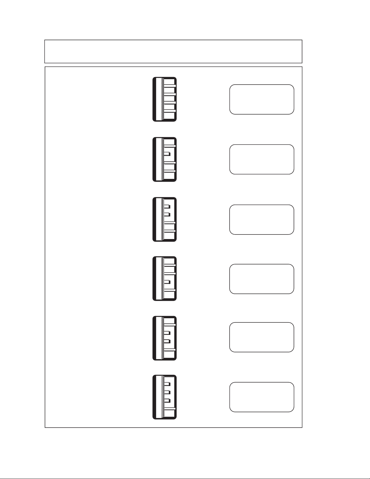
SETTING THE DELIVERY MODE
The infusion system allows a selection of six delivery modes: macro (single channel); macro
secondary (dual channel, single dose); macro multidose (dual channel, multidose); micro
(single channel); micro secondary (dual channel, single dose); and micro multidose (dual
channel, multidose). Delivery mode selection is determined by a dual in-line package (DIP)
switch located under the DIP switch cover on the back of the infusion system.
DIP Switch Settings for Each Delivery Mode, illustrates the settings. Table 1-1, LifeCare
5000 Infusion Mode Configurations, lists the infusion system flow parameters for each
delivery mode.
Figure 1-2,
To reset the infusion system delivery mode, refer to Figure 1-2 and Table 1-1, then proceed
as follows:
1. Open the cassette door and remove the cassette.
2. Using a small flat-blade screwdriver, remove the screw from the DIP switch cover.
Remove the cover to expose the DIP switches.
3. Set the DIP switch to the appropriate position for the desired infusion system
delivery mode.
4. Verify the new delivery mode by closing the cassette door with a primed cassette
properly installed in the door.
5. Replace the DIP switch cover and secure it to the infusion system.
Technical Service Manual 1 - 9 430-03714-005
Page 22
SECTION 1 INTRODUCTION
DELIVERY
MODE
MACRO
(Single Channel)
MACRO SECONDARY
(Dual Channel,
Single Dose)
MACRO MULTIDOSE
MACRO MULTIDOSE
(Dual Channel,
(Dual Channel,
Multidose)
Multidose)
DIP SWITCH
SETTING
DISPLAY LEGEND
CONFIRMATION
LIFECARE 5000
LIFECARE 5000
DUAL CHANNEL
LIFECARE 5000
MULTIDOSE
MICRO
(Single Channel)
MICRO SECONDARY
(Dual Channel,
Single Dose)
MICRO MULTIDOSE
(Dual Channel,
Multidose)
Figure 1-2. DIP Switch Settings for Each Delivery Mode
LIFECARE 5000
MICRO MODE
LIFECARE 5000
MICRO MODE
DUAL CHANNEL
LIFECARE 5000
MICRO MODE
MULTIDOSE
05L03002
430-03714-005 1 - 10 LifeCare
®
5000 Series
Page 23

Section 2
WARRANTY
Subject to the terms and conditions herein, Hospira, Inc. herein referred to as Hospira,
warrants that (a) the product shall conform to Hospira's standard specifications and be
free from defects in material and workmanship under normal use and service for a period
of one year after purchase, and (b) the replaceable battery shall be free from defects in
material and workmanship under normal use and service for a period of 90 days after
purchase. Hospira makes no other warranties, express or implied, and specifically
disclaims the implied warranties of merchantability and fitness for a particular purpose.
Purchaser's exclusive remedy shall be, at Hospira's option, the repair or replacement of
the product. In no event shall Hospira's liability arising out of any cause whatsoever
(whether such cause be based in contract, negligence, strict liability, other tort, or
otherwise) exceed the price of such product, and in no event shall Hospira be liable for
incidental, consequential, or special damages or losses or for lost business, revenues, or
profits. Warranty product returned to Hospira must be properly packaged and sent freight
prepaid.
The foregoing warranty shall be void in the event the product has been misused, damaged,
altered, or used other than in accordance with product manuals so as, in Hospira's
judgment, to affect its stability or reliability, or in the event the serial or lot number has
been altered, effaced, or removed.
The foregoing warranty shall also be void in the event any person, including the Purchaser,
performs or attempts to perform any major repair or other service on the product without
having been trained by an authorized representative of Hospira and using Hospira
documentation and approved spare parts. For purposes of the preceding sentence, "major
repair or other service" means any repair or service other than the replacement of accessory
items such as batteries, detachable AC power cords, and patient pendants.
In providing any parts for repair or service of the product, Hospira shall have no
responsibility or liability for the actions or inactions of the person performing such repair
or service, regardless of whether such person has been trained to perform such repair or
service. It is understood and acknowledged that any person other than a Hospira
representative performing repair or service is not an authorized agent of Hospira.
Technical Service Manual 2 - 1 430-03714-005
Page 24

SECTION 2 WARRANTY
This page intentionally left blank.
430-03714-005 2 - 2 LifeCare
®
5000 Series
Page 25

Section 3
SYSTEM OPERATING MANUAL
A copy of a LifeCare 5000 Infusion System System Operating Manual is included with every
infusion system. For convenient reference, insert a copy of the appropriate system
operating manual (or manuals).
If an operating manual is not available, contact Hospira (see Section 6.1, Technical
Assistance).
Technical Service Manual 3 - 1 430-03714-005
Page 26

SECTION 3 SYSTEM OPERATING MANUAL
This page intentionally left blank.
430-03714-005 3 - 2 LifeCare
®
5000 Series
Page 27

Section 4
THEORY OF OPERATION
This section describes the infusion system theory of operation. Related drawings are
provided in
infusion system and provides a brief overview of the electronics, infusion system alarms,
battery, firmware, and mechanics.
Topics covered, in order of presentation, are as follows:
❏ Sequence of operations
❏ Alarm conditions
❏ Battery operation
❏ System malfunction detection
❏ Data retention
❏ Monitors and detectors
❏ System interface description
❏ Printed wiring assembly (PWA) functional description
❏ Mechanical functional description
Section 9, Drawings. The theory of operation gives a general description of the
Note: The flow detector is optional for use with the 1.6 series infusion system. The
DataPort communication accessories, including the junction box, are optional for use
with DataPort equipped 1.6 series infusion systems. These features are discussed in
various subsections.
4.1
SEQUENCE OF OPERATIONS
This section describes OFF status and the sequence of operations associated with ON
status of the infusion system.
4.1.1
OFF STATUS
The infusion system is off when the cassette door is open, or when the door is closed with
no cassette in place. When the infusion system is off, the following occurs:
❏ Infusion system does not operate
❏ LCD and light emitting diode (LED) screen displays are deactivated
Technical Service Manual 4 - 1 430-03714-005
Page 28
SECTION 4 THEORY OF OPERATION
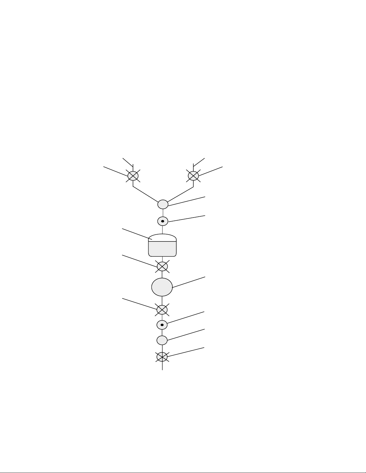
❏ Pumping mechanism valve and plunger motors are returned to home position. Home
position is described as follows. Refer to
Figure 4-1, Fluid Path in the Cassette.
- Plunger is fully retracted
- Inlet valve is open and outlet valve is closed
- Primary valve is open and the secondary valve is closed
❏ Nurse-call alarm circuit is disabled
Under normal conditions, critical data and setup data are retained in memory for four
hours after the infusion system is turned off. Alarm history is retained for an extended
time, and the distal occlusion pressure limit is retained for an extended time at user option,
unless the battery pack is completely discharged or is disconnected.
PRIMARY VALVE
AIR TRAP CHAMBER
INLET VALVE
OUTLET VALVE
PRIMARY
SECONDARY
SECONDARY VALVE
AIR-IN-LINE SENSOR
(PROXIMAL)
PROXIMAL PRESSURE SENSOR
PUMPING CHAMBER
DISTAL PRESSURE
SENSOR
AIR-IN-LINE
SENSOR (DISTAL)
GRAVITY FLOW REGULATOR
AND SHUT-OFF
Figure 4-1. Fluid Path in the Cassette
430-03714-005 4 - 2 LifeCare
06G01004
®
5000 Series
Page 29

4.1 SEQUENCE OF OPERATIONS
4.1.2
ON STATUS
The infusion system is on when a cassette is installed and the door latch is closed. When
the door is closed, the following occurs:
❏ +5 VDC power supply is turned on
❏ LCD and LED screen displays are activated
❏ Infusion system performs a self test, followed by a cassette leak test
❏ Upon successful completion of self test, the touchswitches are activated and the
system is ready for setup and operation
The following sections describe the self test, cassette leak tests, main program software
functions, and operational procedures that occur when the infusion system is turned on.
4.1.2.1
SELF TEST
The infusion system self test performs the following functions:
❏ Initializes all data except the following:
-Alarm history data
- User selected occlusion pressure limit setting (unless a data retention interval of
greater than four hours has elapsed, at which time the default pressure setting is
initialized)
❏ Tests random access memory (RAM) and read only memory (ROM)
❏ Checks failure monitor circuit status
❏ Tests LED and LCD screen displays
❏ Tests the audible alarm
❏ Checks critical data integrity
When the self test successfully completes, the LCD screen displays: SELF TEST: OK. The
cassette leak tests follow immediately. If the self test or the cassette leak tests fail, the
infusion system is in a system malfunction condition (
Detection).
4.1.2.2
see Section 4.4, System Malfunction
CASSETTE LEAK TESTS
Note: If the [START] touchswitch is pressed during the cassette leak tests, the LCD
screen displays: SELF TEST IN PROGRESS PLEASE WAIT.
In LifeCare 5000 infusion systems, cassette valve integrity is tested by the leak tests. Leak
tests immediately follow the infusion system self test. The cassette leak tests consist of
three stages, as follows:
Technical Service Manual 4 - 3 430-03714-005
Page 30

SECTION 4 THEORY OF OPERATION
1. The primary and secondary valves and the outlet valve close. The plunger moves
forward until proximal pressure increases by approximately 2.0 psig (13.8 kPa). If
proximal pressure does not reach 2.0 psig (13.8 kPa) within 40 steps, the test fails.
The plunger again moves forward 110 steps or until proximal pressure reaches
psig (55.1 kPa). If proximal pressure does not increase to the proper level, the
8.0
test fails.
Note: Failure of proximal pressure to reach 8.0 psig (55.1 kPa) may be caused
by excessive air in the air trap chamber.
After five seconds, the pressure drop is measured. If the pressure drops more
than 2.0 psig (13.8 kPa), the test fails. At this point, the primary and secondary
valves and the outlet valve have been tested.
2. All four valves close. The plunger is retracted, creating a vacuum in the pumping
chamber. Proximal pressure drop is checked, and then verified again in five seconds.
A drop in pressure during this time indicates a failed inlet valve.
3. The inlet valve opens and the plunger retracts to the home position, relieving
pressure within the cassette. The primary valve opens and the plunger advances
78 steps. The amount of air flowing past the proximal air detector is monitored, and
the value is used to compute the delivery compensation for concurrent fluid delivery.
The plunger again retracts to the home position. The motors are initialized, the
outlet valve closes, and the inlet and primary valves open.
If any of the leak tests fail, the LCD screen displays: STOPPED SYSTEM RETEST
REQUIRED PRESS RESET. After the [RESET] touchswitch is pressed, the LCD screen
displays: STOPPED OPEN DOOR AND REPRIME SET. The cassette should be reprimed
and the door closed, which starts a new self-test routine. If the leak test fails again, replace
the cassette. If the leak test fails with a new cassette, remove the infusion system from
service and
contact Hospira.
Note: An alarm code is stored in the alarm history for any leak test failure.
At the successful conclusion of cassette leak tests, the infusion system is ready for setup
and operation.
4.1.2.3
MAIN PROGRAM SOFTWARE FUNCTIONS
Upon successful completion of the infusion system self test and the cassette leak tests,
the touchswitches become active and the main program software performs the following
functions:
❏ Activates the 10 millisecond (ms) clock and other timers
❏ Activates the watchdog monitor
❏ Updates I/O flag information
❏ Activates the audio processor
❏ Monitors the cassette sensor
❏ Monitors dose delivery against dose limit
❏ Monitors the system for alarm conditions; generates audible alarm if condition exists
❏ Activates the three motors for pumping
❏ Activates the keyboard
430-03714-005 4 - 4 LifeCare
®
5000 Series
Page 31

4.1 SEQUENCE OF OPERATIONS
❏ Activates message and numeric displays
❏ Checks motor rate against selected rate
❏ Activates the nurse call relay
❏ Activates rolling data routine
❏ Checks microprocessor operation
❏ Performs RAM memory test
❏ Performs ROM checksum test
❏ Monitors accumulated volume data
❏ Monitors DataPort functions
4.1.2.4
SETUP
If a flow detector is attached, refer to Section 4.6.4, Flow Detector.
During the operational sequence, pressing the [RESET] touchswitch returns the infusion
system to setup.
When the touchswitches are active, the infusion system is ready for setup. During setup,
the following occurs:
❏ Pumping mechanism is inactive and the plunger retracts from the cassette to home
position
❏ LCD message panel prompts the user to enter therapy settings through a sequence
of menus (see the LifeCare 5000 System Operating Manual for more detailed
instructions). When infusion system setup is complete, the LCD screen displays:
SETTING COMPLETE PRESS START OR REVIEW/CHANGE.
❏ Audible alarm beeps once per minute if there is no touchswitch activity
❏ Cassette door can be opened without an audible alarm
❏ If setup activity exceeds five minutes, the infusion system sounds an alarm
❏ All alarms are prevented during setup, except the following:
- STOPPED, DEAD BATTERY
-CHECK SET
- Malfunction alarms
Upon infusion system setup completion, previous settings may be changed and current
settings and delivery mode can be reviewed.
4.1.2.5
OPERATION
The normal operating cycle can begin only after appropriate therapy settings have been
entered and the [START] touchswitch is pressed. Pressing the [START] touchswitch
initiates the following:
❏ Pumping mechanism drives the cassette at the user-set delivery rate
❏ User-set delivery rate and total volume are displayed continuously
Technical Service Manual 4 - 5 430-03714-005
Page 32

SECTION 4 THEORY OF OPERATION
❏ Front panel touchswitch controls are inhibited, except the following:
- [REVIEW/CHANGE]
- [RESET]
-[SILENCE]
- Titration function
Note: See the appropriate system operating manual for additional
information.
❏ Alarm circuits are active
Infusion system operation is interrupted whenever the system detects an alarm,
malfunction, or open door. Opening the door during setup, normal operation, or after
completion of operation initiates a wait period of 10 seconds (sleep mode). At the end of
the wait period, the +5 VDC power supply is turned off and the LCD displays are
deactivated.
4.2
ALARM CONDITIONS
When the infusion system detects an alarm condition, the following occurs:
❏ Pumping mechanism either drives the cassette at the keep vein open (KVO) rate or
it stops, depending on the alarm type (
Actions).
see Table 6-1, Alarm Codes and Corrective
Note: The KVO rate is the lesser of 1 milliliter per hour (ml/hr) or the user-set primary
delivery rate when operating in primary mode. When operating in secondary or
concurrent mode, the infusion system reverts to the KVO rate if primary dose end is
reached prior to secondary dose end. If secondary dose end is reached prior to primary
dose end, the infusion system reverts to primary rate and continues to primary dose
end, then reverts to KVO rate. If the callback feature is enabled, an alarm sounds
when delivery of the secondary dose ends. The alarm condition allows the user to
change the secondary container, if required (see LifeCare 5000 System Operating
Manual for detailed instructions).
❏ LCD screen displays the appropriate alarm message (see Table 6-1)
❏ If active, the nurse-call circuit signals that an alarm condition exists for all alarms
except the POWER FAILURE alarm
❏ Alarm sounds
❏ If the audible alarm can be silenced, the [SILENCE/NO] touchswitch is activated
An alarm condition can be exited by pressing the [RESET] touchswitch or opening the
cassette door. Refer to
information.
Section 6, Troubleshooting, for alarm and malfunction code
430-03714-005 4 - 6 LifeCare
®
5000 Series
Page 33

4.3 BATTERY OVERVIEW
4.3
BATTERY OVERVIEW
Proper battery use and maintenance are essential for optimum infusion system operation.
Should the battery pack require replacement, refer to
Replacement.
Factors that most commonly affect battery life are the depth and frequency of discharge
and the length of the recharge period. Storage time and room temperature may also affect
battery life. When the infusion system is neither connected to AC (mains) power, nor
operating, the battery pack retains 50 percent of a full charge for at least one month.
The sealed battery pack can be damaged by misuse. The primary cause of damage is
leaving the battery pack in a less than fully charged state. Battery damage can occur in
a matter of hours. Damage results in a permanent loss of battery capacity. The amount
of lost capacity depends on the degree of discharge, the storage temperature, and the
length of time the battery was stored in a discharged state.
4.3.1
DEPTH OF DISCHARGE
Section 7.2.2, Battery Pack
When the battery pack is discharged below 7.4 VDC while the infusion system is operating,
the alarm sounds and the LOW BATTERY message displays on the LCD screen. Although
continuing to operate the infusion system is not recommended, the battery pack provides
power until discharged to approximately 7 VDC. At approximately 7 VDC, the DEAD
BATTERY alarm activates and infusion system operation ceases.
CAUTION: When the LOW BATTERY alarm sounds, connect the infusion system to
AC (mains) power.
If the battery pack is frequently discharged to the DEAD BATTERY threshold, battery life
is compromised due to sulfation, a reduction in charge carrying ability, and the formation
of a lead precipitate.
4.3.2
BATTERY RECHARGE
Battery recharge occurs any time the infusion system is connected to AC (mains) power.
It is recommended that the infusion system be connected to AC (mains) power whenever
practicable to maximize available battery charge during patient transport or ambulation.
The power switch does not have to be on for the battery to recharge.
A discharged battery pack may be recharged to 80 percent of its previous capacity during
a 16 hour recharging period while the infusion system operates at a delivery rate of
125
ml/hr or lower.
Note: A permanently-damaged battery pack cannot be recharged to full capacity.
Technical Service Manual 4 - 7 430-03714-005
Page 34

SECTION 4 THEORY OF OPERATION
4.3.3
OPERATIONAL REQUIREMENTS
The infusion system is intended to operate on battery power on an exception basis only.
The battery pack provides emergency backup power during AC (mains) power failure, or
inadvertent disconnection of the AC (mains) power cord. The battery pack also allows
temporary portable operation during short periods while a patient is moved from one
location to another.
If the infusion system is used frequently on battery power, battery life may be significantly
reduced. As a general rule, the more often the battery pack is discharged and recharged,
the sooner it needs replacement.
The infusion system should be connected to AC (mains) power whenever possible to ensure
the battery pack is always in a charging condition. To prolong battery life, keep the infusion
system connected to AC (mains) power when available.
If the infusion system operates on battery power until the LOW BATTERY message appears,
the battery pack may be permanently damaged. If the LOW BATTERY message appears,
connect the infusion system to AC (mains) power immediately to minimize the risk of
battery damage.
Note: The battery pack quickly degrades if repeatedly cycled from a charged state to
a deeply discharged state.
4.3.3.1
BATTERY OPERATION
When the infusion system operates on battery power, the red LED battery symbol on the
front panel is illuminated. The microprocessor monitors battery voltage to prevent
excessive battery discharge. The infusion system alerts the user to any battery alarm
condition.
If the infusion system operates on continuous battery power, the following sequence of
alarm conditions can occur:
❏ Upon detecting a low battery threshold, the LCD screen displays: LOW BATTERY.
This message alternates with routine status messages. An intermittent alarm sounds.
The infusion system continues pumping.
Note: The low battery alarm stops if the infusion system is connected to AC
(mains) power. The battery pack is in a discharged state, but is being recharged.
❏ If the infusion system is not connected to AC (mains) power, approximately 30
minutes after the LOW BATTERY message appears (for a new, fully charged battery),
the LCD screen displays: STOPPED - DEAD BATTERY. The audible alarm sounds.
In addition, the following occurs:
- Infusion system stops pumping
- Plunger retracts to the home position
- Primary valve opens and secondary valve closes
430-03714-005 4 - 8 LifeCare
®
5000 Series
Page 35

4.4 SYSTEM MALFUNCTION DETECTION
- Outlet valve closes
- Inlet valve opens
- LCD backlight is deactivated
Note: If the infusion system is connected to AC (mains) power, the STOPPED
DEAD BATTERY alarm ceases. The battery pack is in a discharged state, but
is being recharged.
❏ If the infusion system is not connected to AC (mains) power, the LCD screen goes
blank approximately 10 minutes after displaying the message: STOPPED - DEAD
BATTERY. The audible alarm sounds.
Note: When the continuous audible alarm sounds, the infusion system is in
hardware shutdown. Critical data in infusion system memory is lost. If the
infusion system door is opened, the alarm stops immediately.
CAUTION: Minimize the time the infusion system operates on battery power.
Recharge the battery pack as soon as possible after battery operation.
4.3.3.2
BATTERY CHARGER OPERATION
This section describes the battery charging function of the battery charger PWA.
When the battery pack is discharged (terminal voltage falls below +8 VDC), charging occurs
at the 1 ampere (A) limit for as long as required. As the terminal voltage increases to +9.4
VDC, the current decreases until a current of 220 milliamperes (mA) is reached. The charge
current is maintained at a constant 220 mA level and the terminal voltage again continues
to increase toward +10 VDC. Upon reaching the +10 VDC level, a 60-minute timer is
activated. The 220 mA charging rate is maintained during the 60-minute period, and then
shuts off. The terminal voltage immediately moves towards the voltage of a fully charged
battery (approximately 8.6 V). Because less than 20 mA charging current is now required,
the float charger remains off. If AC (mains) power is disconnected during the 60-minute,
220 mA charge period, charging continues for the balance of this time after reconnecting
AC (mains) power.
When the battery pack is partially discharged (terminal voltage is greater than +8 VDC),
charging occurs at the constant voltage of +9.4 VDC. When the charging current reduces
to between 20 and 25 mA, the charger shuts off.
When battery charging is interrupted prior to full charge, the charger continues to charge
the battery pack upon reconnection to AC (mains) power.
4.4
SYSTEM MALFUNCTION DETECTION
Two failure states can occur when the system detects a malfunction: the core failure state,
and the peripheral failure state.
Technical Service Manual 4 - 9 430-03714-005
Page 36

SECTION 4 THEORY OF OPERATION
4.4.1
CORE FAILURE STATE
A core failure state occurs when the failure monitor detects a malfunction that causes a
system failure. During the core failure state, the following occurs:
❏ Pumping mechanism stops
❏ Continuous alarm sounds
❏ System-prompting function is inhibited
4.4.2
PERIPHERAL FAILURE STATE
A peripheral failure state occurs when any one of the following malfunctions are detected:
❏ Monitor circuit failure
❏ Mechanical malfunction
❏ Noncritical electronic circuitry malfunction
❏ Short duration, nonpermanent memory failure
❏ Control override by the failure monitor circuit
During the peripheral failure state, the following occurs:
❏ Pumping mechanism stops
❏ An alarm code is displayed and the LCD screen flashes: MALFUNCTION (see
Table 6-1, Alarm Codes and Corrective Actions)
❏ Alarm sounds
❏ Nurse-call circuit is activated
4.4.3
EXITING FROM FAILURE STATE
Exit from failure state is accomplished by opening the cassette door, or discharging the
battery pack.
Note: If the alarm is not silenced by opening the cassette door, remove and replace
the battery pack (
4.5
DATA RETENTION
see Section 7.2.2, Battery Pack Replacement).
The following sections describe critical data and alarm history data, and how they are
retained in memory.
®
430-03714-005 4 - 10 LifeCare
5000 Series
Page 37

4.5 DATA RETENTION
4.5.1
CRITICAL DATA RETENTION
Critical data is held in infusion system memory for four hours after the infusion system
enters the off status condition. Critical data includes the following:
❏ Status condition
❏ Activity state
❏ Dose functions
❏ Volume delivered
❏ Delivery rates
❏ Dose limits
❏ Doses delivered
Memory hold time is restored by returning the infusion system to the setup/operating
status condition (
Any of the following result in critical data loss:
see Section 4.1.2, On Status).
❏ Four hours elapse after the infusion system is shut off
❏ Battery pack is completely discharged or is disconnected
❏ System malfunction occurs
A user-selected occlusion pressure limit setting is retained in memory unless the battery
pack discharges or is disconnected.
Once critical data has been lost, the infusion system reverts to default values in the setup/
operating mode.
4.5.2
ALARM HISTORY ERROR CODES
Alarm history is a rolling history of alarms and malfunctions. To display alarm history,
press the [REVIEW/CHANGE] touchswitch twice during the first three-to-five seconds
after the LCD screen displays: SELF TEST : OK.
The alarm history screen displays up to 15 alarm and malfunction codes, with the most
recent appearing in the lower right corner of the screen. Alarm history is retained in
memory until any one of the following occurs:
❏ Infusion system is disconnected from AC (mains) power and the battery pack is
disconnected
❏ Infusion system is not connected to AC (mains) power and the battery pack reaches
the DEAD BATTERY alarm condition
❏ An AC (mains) power failure occurs, and the infusion system operates on battery
power until the DEAD BATTERY alarm condition is reached
Technical Service Manual 4 - 11 430-03714-005
Page 38

SECTION 4 THEORY OF OPERATION
4.6
MONITORS AND DETECTORS
The monitoring and detection system consists of fluid sensors in the mechanism assembly,
two bubble sensors in the cassette, microprocessor-controlled flow alarm algorithms, and
associated electronics. The ultrasonic bubble sensors detect air at the inlet and outlet of
the cassette pumping chamber.
4.6.1
PRESSURE SENSING SYSTEM
The pressure sensing system senses occlusions from the distal and the proximal pressure
sensors, as described in the following sections.
4.6.1.1
DISTAL OCCLUSION
Distal occlusion is defined as an occlusion in the administration set distal to the cassette.
Pressure within the cassette is measured by sensing the strain in a four element strain
gauge bridge that is bonded to a steel leaf spring. The microprocessor monitors absolute
pressure. If the absolute pressure limit is exceeded, a DISTAL OCCLUSION alarm occurs
and pumping ceases.
The distal occlusion alarm is triggered by any one of the following conditions:
❏ Measured pressure exceeds 10 psig (68.9 kPa) for approximately 1.2 seconds
❏ Measured pressure exceeds the user-selected pressure limit for approximately 12
seconds
❏ Instantaneous pressure exceeds 10 psig (68.9 kPa) and the plunger motor slips
❏ Measured pressure exceeds user selected pressure limit at the time the [START]
touchswitch is pressed
4.6.1.2
PROXIMAL OCCLUSION
Proximal occlusion is defined as an occluded primary or secondary administration set
proximal to the cassette. Proximal occlusion is sensed by measuring the output of the
proximal sensor. If the proximal line is occluded, a vacuum forms in the air trap chamber,
which is sensed by the proximal sensor. If the proximal occlusion is present after three
cycles, the proximal occlusion alarm sounds.
4.6.2
AIR-IN-LINE DETECTION
Air-in-line detection takes place both proximal and distal to the cassette, as described in
the following sections.
430-03714-005 4 - 12 LifeCare
®
5000 Series
Page 39

4.6 MONITORS AND DETECTORS
4.6.2.1
PROXIMAL AIR-IN-LINE DETECTION
A proximal air-in-line alarm is triggered if air is detected by the proximal air sensor for a
continuing bolus of air equivalent to approximately 600 microliters (µL), or if air is sensed
for intermittent cumulative boluses of air equivalent to approximately 1.2 ml.
When cumulative air boluses equivalent to approximately 600 µL are registered, and the
infusion system is programmed for secondary delivery, autobackpriming is triggered in
order to backprime excess accumulated air into the secondary container.
4.6.2.2
DISTAL AIR-IN-LINE DETECTION
A distal air-in-line alarm is triggered if air is detected by the distal air sensor for a
continuing bolus of air equivalent to approximately 100 µL, or if air is sensed for
intermittent cumulative boluses of air equivalent to approximately 240 µL out of 2 ml total
volume. When the cassette door is opened, the sensor is reset.
Before the distal air-in-line alarm is activated, the infusion system pushes the air bubble
approximately 20 motor steps forward to a position where it is visible in the tubing.
4.6.3
MALFUNCTION DETECTION
The infusion system diagnoses two types of hardware malfunctions: those detected during
self test, and those that occur during normal operation.
Refer to the tables in Section 6, Troubleshooting, for a list of alarm and malfunction codes.
Refer to Table 6-1, Alarm Codes and Corrective Actions, for LCD messages, possible causes,
and recommended corrective actions where applicable.
Malfunction codes can be reviewed by pressing the [REVIEW/CHANGE] touchswitch twice
during the first three-to-five seconds after closing the door. The LCD screen displays the
last 15 alarm or malfunction codes, with the most recent appearing in the lower right-hand
corner of the screen.
4.6.4
FLOW DETECTOR
Use of a flow detector is optional for LifeCare 5000 infusion systems.
The flow detector clips around the drip chamber and optically senses drops falling within
the chamber. The device consists of a set of three phototransistors and two infrared LEDs,
together with infrared and limited acceptance angle filters, all of which are contained in
a plastic housing.
Technical Service Manual 4 - 13 430-03714-005
Page 40

SECTION 4 THEORY OF OPERATION
4.6.4.1
FLOW DETECTOR CONNECTED DURING RESET
If a flow detector is connected to the infusion system during reset or setup, no dose limit
setting is required. If no dose limit is set, the infusion system runs until the primary
container empties. The flow detector then senses the absence of flow, generates an audible
alarm, and the LCD screen displays: EMPTY CONTAINER PRIMARY. The pumping rate is
decreased to KVO.
4.6.4.2
FLOW DETECTOR NOT USED
If a flow detector is not connected to the infusion system, a dose limit must be set for
primary delivery during reset; otherwise, the infusion system will not leave setup when
the [START] touchswitch is pressed.
4.6.4.3
FLOW DETECTOR DISCONNECTED
If the flow detector is disconnected while the infusion system is operating, a FLOW
DETECTOR DISCONNECTED alarm is generated and the infusion system stops pumping.
To silence the alarm, press the [RESET] touchswitch. Follow the screen prompts to set a
dose limit for primary delivery. Press [START] to continue delivery.
4.7
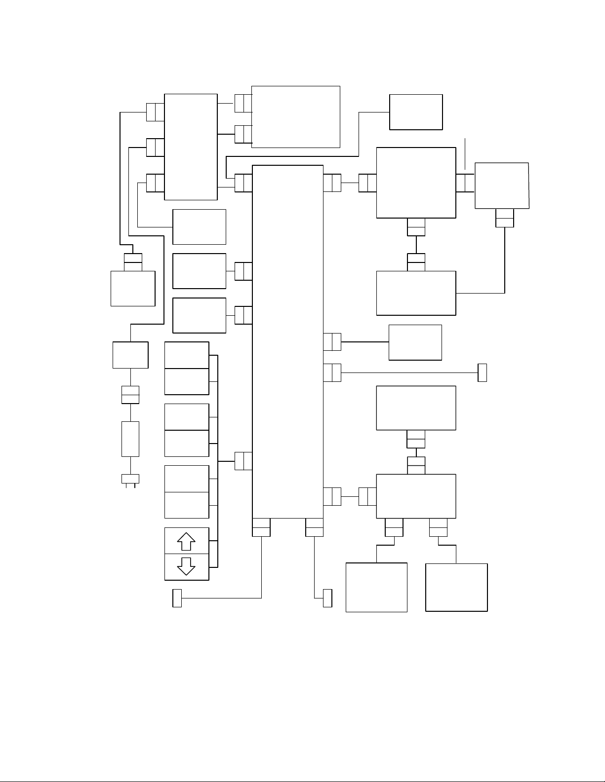
SYSTEM INTERFACE DESCRIPTION
The interfaces between the principal hardware subassemblies in the infusion system are
shown in
Section 9, Drawings, for the system interconnect schematic shown in Figure 9-7,
Interconnect Schematic. The interfaces are categorized as follows:
❏ Power interface
❏ User interface
❏ Motors and valve interface
❏ Sensor interface
❏ Display interface
❏ Main and I/O interface
A description of the interfaces and the signal flow between them follows.
Figure 4-2, LifeCare 5000 System Interface Block Diagram. See
430-03714-005 4 - 14 LifeCare
®
5000 Series
Page 41
4.7 SYSTEM INTERFACE DESCRIPTION
P/J26
+8 VDC
BATT
PAC K
XMFR
T1
P/J27
F1
F2
P/J18
P/J16
P/J17
POWER
SUPPLY
PWA
AUDIBLE
ALARM
I/O
VALV E
MOTOR
PIGGYBK
VALV E
MOTOR
START
RESET
CLEAR
REVIEW
CHANGE
P/J10
P/J1
P/J2
P/J4
P/J8
P/J9
BATTERY
CHARGER
PWA
I/OPWA
P/J3
P/J7
P/J23
P/J2
AUDIBLE
ALARM
SWITCH
MAIN
P/J11
P/J25
DISPLAY
ASSEMBLY
PLUNGER
MOTOR
BUBBLE
SENSOR
PWA
LCD
PWA
P/J1
LED
DISPLAY
PWA
P/J15
NURSE-
CALL
JACK
P/J21
P/J20
SENSOR
PWA
P/J25
PROXIMAL
PRESSURE
SENSOR
AC
INPUT
YES
ENTER
SILENCE
NO
P/J24
P/J5 P/J6
P/J19
P/J22
DISTAL
PRESSURE
SENSOR
(1.6ONLY)
FLOW DETECTOR
JACK
DATAPORT JACK
(1.6 SERIES DATAPORT-
EQUIPPED PUMPS ONLY)
06G01003
Figure 4-2. LifeCare 5000 System Interface Block Diagram
Technical Service Manual 4 - 15 430-03714-005
Page 42

SECTION 4 THEORY OF OPERATION
4.7.1
POWER INTERFACE
Both AC (mains) input power and +8 VDC battery power are inputs to the power supply
PWA (
4-2, LifeCare 5000 System Interface Block Diagram). The power supply PWA provides
audio signal power to the audible alarm and DC power levels, in addition to supplying
various control signals to the I/O PWA. These interfaces are described in the following
sections.
4.7.1.1
AC POWER INTERFACE
The infusion system is connected to AC (mains) power through the power cord, which
connects into the back of the infusion system. The AC (mains) input is routed to F1 and
F2 and then to a power transformer (T1) through connector P/J27. From the output of
T1, AC (mains) power is connected to the power supply PWA through connector P/J16.
4.7.1.2
DC POWER INTERFACE
The +8 VDC rechargeable battery pack is connected to the power supply PWA through the
connector P/J26, which routes battery power to P/J18 on the power supply PWA. When
the infusion system operates on AC (mains) power, output of the charging circuitry on the
power supply PWA recharges the battery pack. When the infusion system operates on
battery power, the battery pack supplies the infusion system with +8 VDC power through
the same interface.
4.7.1.3
POWER SUPPLY PWA INTERFACE
The power supply PWA provides an audio drive signal to the audible alarm assembly
through P/J17. The power supply PWA also provides power and signal interfaces with the
I/O PWA through P/J4.
4.7.1.4
BATTERY CHARGER PWA INTERFACE
The battery charger PWA connects to two cables, and is routed to the power supply PWA
through connectors P/J1 and P/J2. Connector P/J1 connects the power supply PWA to
the voltage detector and current limiter circuitry on the battery charger PWA. Connector
P/J2 connects the power supply PWA to the current sensing circuitry on the battery
charger PWA.
430-03714-005 4 - 16 LifeCare
®
5000 Series
Page 43

4.7 SYSTEM INTERFACE DESCRIPTION
4.7.2
USER INTERFACE
The user interface consists of the front panel touchswitches, the nurse-call jack interface
on the infusion system back panel, and the DataPort interface on the infusion system
back panel. These interfaces, illustrated in
Block Diagram, are described in the following sections.
4.7.2.1
FRONT PANEL INTERFACE
The front panel interface consists of inputs to the I/O PWA from the eight front panel
touchswitches through P/J10.
4.7.2.2
NURSE-CALL INTERFACE
The nurse-call jack on the infusion system back panel (labeled NURSE CALL) interfaces
with the I/O PWA through P/J23.
Figure 4-2, LifeCare 5000 System Interface
4.7.2.3
DATAPORT INTERFACE
The DataPort interface makes it possible to connect from 1 to 15 DataPort equipped
infusion systems to a host computer through a system of communication cables. A
separate junction box attaches to the back I/O port panel on the infusion system through
a DB-15 connector, P/J22. Two six-pin modular jacks (J1 and J2) on the junction box
connect to the communication bus and to another infusion system.
An infusion system may be removed from the communication bus without breaking the
bus connection by disconnecting the junction box from the infusion system.
DIP switches in the junction box create a hard identification (ID), or location, for each
infusion system. Hard ID values between 1 and 15 are supplied by the attached junction
box. The hard ID may be written on a label on the exterior of the junction box. The host
computer identifies the location of the infusion system using this hard ID.
Note: DIP switch setup instructions are described on the insert accompanying the
junction box.
4.7.3
MOTORS AND VALVES INTERFACE
The motors and valves in the infusion system are powered and controlled by the I/O PWA.
The plunger motor receives +6.5 VDC power and motor drive signals through P/J7. The
I/O valve motor receives +6.5 VDC power and motor drive signals through P/J8. The
primary/secondary valve motor receives +6.5 VDC power and motor drive signals through
P/J9.
Technical Service Manual 4 - 17 430-03714-005
Page 44

SECTION 4 THEORY OF OPERATION
4.7.4
SENSOR INTERFACE
The sensor interface includes the following interfaces:
❏ Distal pressure sensor interface with sensor PWA
❏ Proximal pressure sensor interface with sensor PWA
❏ Bubble sensor PWA interface with sensor PWA
❏ Flow detector interface with I/O PWA
❏ I/O PWA interface with sensor PWA
4.7.4.1
PRESSURE SENSOR INTERFACE
The distal, proximal, and bubble sensors connect to the sensor PWA which connects to
the I/O PWA. Bubble sensing is performed by the bubble sensor PWA which interfaces
with the sensor PWA through connectors P/J21 on the bubble sensor PWA and P/J20 on
the sensor PWA. Distal and proximal pressure sensor signals are routed directly to the
sensor PWA through P/J19 and P/J25, respectively, on the sensor PWA. The sensor PWA
interfaces with the I/O PWA through connector P/J6 on the sensor PWA and connector
P/J5 on the I/O PWA.
4.7.4.2
FLOW DETECTOR INTERFACE
Refer to Section 4.6.4, Flow Detector, for flow detector information. The flow detector
connector on the back of the infusion system interfaces with the I/O PWA connector P/
J24, as shown in
Figure 4-2, LifeCare 5000 System Interface Block Diagram.
4.7.5
DISPLAY INTERFACE
The display interface consists of the LED display and the LCD screen display on the
infusion system front panel. The display interface involves the main PWA which connects
directly to the LED PWA through P/J1 and to the LCD screen display through P/J11 on
the main PWA and P/J25 on the LCD screen display. The LED display PWA provides power
to the LCD screen display PWA through connector P/J15.
4.7.6
MAIN AND I/O INTERFACE
The main PWA receives power through the I/O PWA, through connector P/J3 on the I/O
PWA, directly into connector P/J2 on the main PWA.
430-03714-005 4 - 18 LifeCare
®
5000 Series
Page 45

4.8 PWA FUNCTIONAL DESCRIPTION
4.8
PWA FUNCTIONAL DESCRIPTION
This section provides a functional description and a functional block diagram of the
infusion system PWAs. For circuit details, refer to the schematics for each PWA in
Section 9, Drawings. International schematics are also located in Section 9 and should be
referred to accordingly.
4.8.1
MAIN PWA
As shown in Figure 4-3, Main PWA Functional Block Diagram, the main PWA provides
microprocessor control for the infusion system. For main PWA schematics, refer to Figure
9-15, 1.6 Series Main PWA Schematic. Basic circuitry on the main PWA is as follows:
❏ Microprocessor unit (MPU) and 8 megahertz (MHz) clock
❏ 455 kilohertz (kHz) second clock source
❏ 48K bytes of erasable/programmable read only memory (EPROM)
❏ 2K bytes of RAM
❏ Custom integrated circuit (IC) logic for selection of various memory functions
❏ Analog-to-digital (A/D) converter
❏ DC-to-DC converter
Technical Service Manual 4 - 19 430-03714-005
Page 46
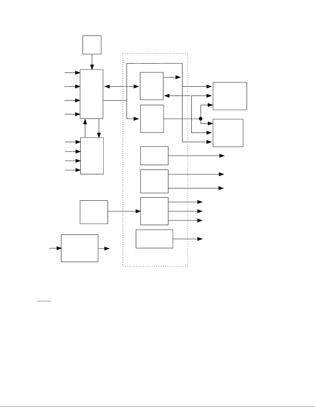
SECTION 4 THEORY OF OPERATION
XTAL
8MHZ
A4-A7
MUXAD
ADCBAT
VREF 2.5
PRESSURE
MPU
U8
ADC
U7
SECOND
CLOCK
455 KHZ
CIRCUIT
AD0-7
A8-A15
ADRS/
DATA
XCVR
ADRS
DECODE
LCD
LATCHES
LED
LATCHES
COUNTER
DIVIDER
CS
A0-A14
D0-D7
A0-A13
DSP01-07
SEGA-G,DP
CHAR1-5
IRQN
PP21 (WDPULS)
PP22 (BAUD RATE)
EPROM
U3,U4(1.5)
U3 (1.6)
RAM
U5
LCD
INTERFACE
LED SEG
CONTROL
LED CHAR
CONTROL
+5V
DC/DC
CONVERTER
U1
-5V
U9
WATCHDOG
LOGIC
GATE ARRAY
SRSTN
05L03005
Figure 4-3. Main PWA Functional Block Diagram
4.8.1.1
MPU AND CLOCK
The 40-pin Hitachi HD63B03R complementary metal-oxide-semiconductor (CMOS) MPU
on the main PWA is the central processing unit (CPU). The CPU contains 128 bytes of
RAM, the serial communication interface (SCI), the parallel input/output (I/O) ports, and
a multifunction timer. The CPU is address and data bus compatible with the Motorola
MC6800 family of microprocessors. In addition, RAM can be expanded to 64K bytes.
The MPU clock consists of the 8 MHz crystal Y2 and capacitors C10 and C11. Y2 is
internally divided by four to give a 2 MHz system cycle frequency.
®
430-03714-005 4 - 20 LifeCare
5000 Series
Page 47

4.8 PWA FUNCTIONAL DESCRIPTION
4.8.1.2
SECOND CLOCK SOURCE
The second clock source contains the 455 kHz resonator Y1, the inverter U2, and
capacitors C8 and C9. The second clock source performs the following functions:
❏ Watchdog pulse source
❏ LED refresh interrupt timer
❏ Baud rate generator
4.8.1.3
EPROM, RAM, AND MEMORY PROTECTION
Program memory resides in the 27C512 EPROM, U3. U3 has 64K byte capacity of which
56K is used. The remaining address space is used for RAM and I/O mapping.
2K bytes of system RAM are provided by the MK48T128 U5, which also provides real-time
clock (RTC) capability. The 48T128 contains an internal battery which provides power for
memory retention and clock functions when the system 5 V supply is off.
Memory block decoding is performed by the custom logic IC U9, and by NOR gate U4A.
RAM memory is decoded from 20(16) to 7FF(16). I/O space is decoded between 1000(16) and
1FFF
(16). EPROM space is decoded from 2000(16) to FFFF(16).
RAM memory is protected from spurious writes by NAND gate U6A during system power
down. The RAMSEL signal from U9 is AND gated with REGON. This allows writes to the
RAM only when +5 V is available. REGON, provided by the power supply, is brought low
immediately when the infusion system is turned off. RAMSEL is forced low by a system
reset and during power up.
4.8.1.4
CUSTOM LOGIC IC
The custom IC, U9, is a HCMOS 84-pin gate array that provides the following functions:
❏ Address decoding
❏ Bus interfacing
❏ Timing control
❏ LED/LCD interfacing
❏ Power up/system reset control
4.8.1.5
A/D CONVERSION
IC U7 is an 8 bit A/D converter with four multiplexed inputs. Channel 0 (pin 3) converts
the distal pressure amplifier output. Channel 1 (pin 4) converts the proximal pressure
amplifier output.
Technical Service Manual 4 - 21 430-03714-005
Page 48

SECTION 4 THEORY OF OPERATION
Channel 2 (pin 5) measures the ADCBAT and the 2.5 V reference (VREF2.5). Signal
switching is performed by U4 on the I/O PWA. The reference voltage is tested at power up
self test only.
Channel 3 converts the output voltage from the analog multiplexer on the display PWA.
The multiplexer switches between the LED test voltage or current, the OVPREF signal from
the power supply, and the output of the flow detector (DROPFB).
4.8.1.6
-5 VOLT GENERATION
Voltage converter U1 and associated components generate -5 VDC from the 5 V supply.
A negative voltage set by potentiometer R1 is used to adjust the LCD screen viewing angle.
4.8.2
I/O PWA
The I/O PWA provides interface between the MPU and infusion system hardware such as
the front panel, motors, alarms, sensors, and nurse-call relay (
DataPort Option Functional Block Diagram). The I/O PWA contains the following circuitry:
Figure 4-4, I/O PWA with
❏ Custom I/O IC
❏ Motor drivers
❏ Nurse-call relay and control circuits
❏ Communications port (on selected units)
❏ Configuration switches
430-03714-005 4 - 22 LifeCare
®
5000 Series
Page 49
4.8 PWA FUNCTIONAL DESCRIPTION
FLOW
DETECTOR
CIRCUITS
CONFIGURATION
SWITCHES
KEYBOARD
INPUTS
SENSOR
INPUTS
COMMUNICATIONS
PORT
NOTE: COMMUNICATIONS
PORT HARDWARE VARIES
WITH CONFIGURATION
8
6
3
3
CPU
ADDRESS
I/O
CUSTOM
IC
U3
8
CPU
DATA
CONTROL
4
4
4
MISC
OUTPUTS
MOTOR
DRIVERS:
PLUNGER
VALV E
PIGGYBACK
NURSE-
CALL
RELAY
AUDIBLE
ALARM
SWITCH
TO POWER
SUPPLY
05L03006
Figure 4-4. I/O PWA with DataPort Option Functional Block Diagram
4.8.2.1
CUSTOM I/O IC
U3 is a custom CMOS IC which provides I/O expansion for the MPU. Addresses from
1030
(16) through 1033(16) are decoded into output latches or input buffers in this IC. The
custom I/O IC contains the following circuitry:
❏ Bus interface
❏ Hardware watchdog
❏ Reset and power control logic
❏ Sensor interface
❏ Touchswitch interface
❏ Motor control latches
❏ Communication port interface
The hardware watchdog monitors the software integrity by posting a message to the CPU
and then waiting for the CPU to respond. If the CPU fails to respond intelligently, a system
reset occurs.
Technical Service Manual 4 - 23 430-03714-005
Page 50

SECTION 4 THEORY OF OPERATION
During run-time, the CPU monitors the watchdog clock input (6303, pin 9, P21) and
matches it with the watchdog bit (6303, pin 8, P29) when the watchdog clock changes its
state from high to low. The CPU generates the matching bit within 27 ms after transition
has occurred. The matching pattern consists of 8 bits, as 10110100
The watchdog circuit triggers the system reset within 81 ms after power up if the CPU fails
to match the watchdog pattern.
4.8.2.2
(2) after power up reset.
MOTOR DRIVERS
N-channel metal oxide semiconductor field-effect transistor (MOSFET) Q1 through
MO SF ET Q1 2, al on g w it h re si sto r n etw or k ( RN ) 2 through RN4, comprise the driver circuits
for the plunger motor, valve motor, and primary/secondary motor. When turned on, these
transistors sink current from the stepper motor windings. Gate drive for these transistors
is provided by the outputs M1D0 through M3D3, through the resistor networks.
Figure 9-10, Series I/O PWA Schematic shows two sets of motor driver transistors: Q1
through Q12 and Q1A through Q12A. Only one set of transistors is installed in any board;
the two sets of holes allow a choice of transistor packages.
4.8.2.3
NURSE-CALL RELAY CONTROL
Operation of nurse-call relay K1 is controlled by Q15 and Q16. Q15 is turned on under
processor control during any alarm condition. Q16 is turned off by the soft switch
(SOFTSW) line during the power-on self test to prevent unwanted relay activation.
JP3 is a jumper which selects NO or NC operation of the nurse-call circuit. JP3 is
configured at the factory for NO operation. J23 is the back panel connector for the
nurse-call system.
4.8.2.4
DELIVERY MODE SELECTION
Switch (SW)2 is a DIP switch used to set infusion system delivery modes. For DIP switch
configurations, refer to
Settings for Each Delivery Mode.
4.8.2.5
Section 1.10, Setting the Delivery Mode, and Figure 1-2, DIP Switch
DATAPORT OPTION
The DataPort is a computer interface port similar to an RS-232 port, with significant
changes: a hardware address is provided for each infusion system, and the receive (RX)
line is modified to allow multiple infusion systems on a single channel.
The DataPort circuitry on the I/O PWA performs three functions:
1. The DataPort power supply circuit generates 10 V from the +5 V supply. The IC,
U6, (MAX680) is a power supply converter, with capacitors C18, C19, C21 and C22
converting the +5 V to the 10 V. Capacitor C20 decouples the 5 V line.
®
430-03714-005 4 - 24 LifeCare
5000 Series
Page 51

4.8 PWA FUNCTIONAL DESCRIPTION
2. The driver/receiver circuit inverts signals from CMOS levels to EIA standard
RS-232-D levels, and from RS-232-D levels to CMOS levels, respectively. The driver
IC, U5, (LT1039) enables RX line when transmit enable (TXEN) is high, and permits
data transmission. When TXEN is low, the U5 driver is in a high impedance (HI-Z)
state. The receiver portion of IC U5 is turned on at all times. The receiver input
impedance is 30K
Ω, which is high enough to be driven by the host computer.)
3. The clear to send (CTS) circuit raises the line high when it is connected to the
communication bus and the infusion system is turned on. Diode CR7 creates an
OR signal with the rest of the infusion systems on the line. Transistors Q17, Q18,
and resistors R17 and R18 provide a current limit circuit.
4.8.2.6
Ω. (When 15 devices are on line, line impedance is lowered to 2K
FLOW DETECTOR
The flow detector circuit consists of a switchable LED driver (R5, R6, and Q13) and load/
sensing circuitry (R3, R4, C1, CR1, and CR2) for the phototransistors in the flow sensor.
DROPFB is an input to the A/D converter on the main PWA.
Refer to Section 4.8.8, Flow Detector, for a complete description of the flow detector.
4.8.2.7
MISCELLANEOUS I/O CIRCUITRY
Analog switches U4A and U4B select the scaled ADCBAT or the VREF 2.5 as inputs to the
A/D converter on the main PWA. VREF 2.5 is tested during power up. At all other times,
the A/C channel is used to measure the battery state of charge.
4.8.3
POWER SUPPLY PWA
For schematics of the power supply PWA, refer to Figure 9-13 Power Supply PWA Schematic.
The power supply PWA converts AC voltage to DC voltage and provides power control
circuitry for AC (mains) power or battery operation of the infusion system (
Supply PWA Functional Block Diagram). The power supply PWA circuitry includes the
following:
❏ Unregulated DC power supply
❏ AC (mains) line and battery power indication
❏ Power control
❏ +5 VDC supply
❏ VMEM supply
4-5, Power
Technical Service Manual 4 - 25 430-03714-005
Page 52

SECTION 4 THEORY OF OPERATION
❏ Motor power supply
❏ Overvoltage protection
❏ Audible alarm backup
❏ Audible alarm control
❏ Audible alarm self test
❏ Battery pack charging
❏ Battery voltage detection
4.8.3.1
UNREGULATED DC POWER SUPPLY
As shown in Figure 4-5, Power Supply PWA Functional Block Diagram, the unregulated DC
power supply is composed of the power transformer T1, in conjunction with the rectifier
and filter.
The AC (mains) power voltage is supplied to T1 through the power cord and fuses F1 and
F2, located on the back panel, (
T1 is center tapped for full wave rectifying by diodes CR7 and CR8. Under no-load
conditions, the T1 secondary delivers 22 VAC root-mean-square (RMS). Capacitor C11
filters ripple voltage that appears between +RDC and -RDC.
see Figure 9-7, Interconnect Schematic). The secondary of
4.8.3.2
AC (MAINS) LINE AND BATTERY POWER INDICATION
Operating the infusion system on battery power causes the green LED (AC power indicator
on the display PWA) to deactivate and the red LED (battery power indicator) to activate.
The line/battery indicator circuit consists of Q17, CR11, and resistors RN10 (1,2), R21,
and R23.
The BPLEDA signal at P4, pin 37, sources current to the battery power LED indicator
anode on the display PWA through the parallel combination of resistor network RN10 [1,2]
and resistor R21.
When operating on AC (mains) power, Q17 is turned on and shunts current around the
red LED through diode CR11 to turn off the battery power LED indicator. The +RDC supply
sources current through resistor R23 and LPLEDA at P4, pin 38, to the anode of the AC
(mains) power green LED; the cathode of this LED returns to -RDC through P4, pin 40.
430-03714-005 4 - 26 LifeCare
®
5000 Series
Page 53
RECTIFIER
AND
FILTER
4.8 PWA FUNCTIONAL DESCRIPTION
BATTERY
PAC K
INPUT
WAKEUP
SWRDC
OVP S T
WDTRAP
AUDALMN
AC
PWA
XFMR
T1
AUDIBLE
ALARM
CONTROL
BATTERY
CHARGER
PWA
LINE/BATT
POWER
INDICATOR
POWER
CONTROL
BATTERY
CHARGER
CIRCUITS
VMEM
REGULATOR
+5 VDC
REGULATOR
MOT OR
POWER
REGUL A T OR
VMEM
+ 5/ VAN
MOTPWR
6.5V
REGON
VREF
BATTERY
DETECTOR
BADBAT
INITBAT
ALARM
XDUCER
AUDIO
ALARM
SELF-TEST
ALMFLG
+ 5/ VAN
OVPT ST
OVERVOLTAGE
PROTECTOR
OVPREF
OVPVMOFF
+ RDC
06G01002
Figure 4-5. Power Supply PWA Functional Block Diagram
Technical Service Manual 4 - 27 430-03714-005
Page 54

SECTION 4 THEORY OF OPERATION
4.8.3.3
POWER CONTROL
When the infusion system is on, the cassette switch on the sensor PWA is actuated, causing
SWRDC at P4, pin 1, to go high. When SWRDC goes high, a positive pulse is placed on
the base of Q9, through C19 and resistor networks RN7 (1,2) and RN10 (4,5). The base of
Q18 is pulled low by Q9; the Q18 collector brings the REGON line (P4, pin 32) high.
The REGON line enables both the +5 VDC and motor regulators. REGON is also used as
a RAM enable signal (U6, pin 1) on the main PWA. After the processor is started, the
WAKEUP line is held high, which holds REGON high, for as long as the infusion system
is in operation.
If the battery is completely discharged, the BADBAT signal causes the custom IC on the
main PWA to bring WAKEUP low, which causes the infusion system to go into shutdown.
CR12 prevents the base of Q9 from being driven below ground.
4.8.3.4
+5 VDC SUPPLY CONTROL
For the +5 VDC power supply, reference diode U2 adjusts precisely to +2.5 VDC through
potentiometer R2, and connects to the noninverting input at U3-A, through R10 and RN7
(9,10). U2 also sets the +2.5 VDC reference for the +6.5 VDC motor power regular power
supply. U2 receives power from REGON.
The voltage divider, consisting of RN4 (6,7) and RN4 (5,6), feeds back one half of the +5/
VAN output to the inverting input of U3. This input is amplified to drive the base of Q10.
If the +5/VAN output is too low, U3A output (pin 1) goes higher, providing more base drive
to Q10. Q10 then draws more base current from series pass transistor Q13, raising the
output voltage.
U3-B operates as a voltage comparator to limit current. The dividers, consisting of RN4
(8,9) RN4 (9,10), and RN4 (9,11), provide a +135 mV reference to the inverting input of
U3-B. Should the load return current through R6 exceed 1.35 A, the output of U3-B will
go high to turn on Q7 through R11. The collector of Q7 clamps the noninverting input of
U3-B to ground, removes the +2.5 VDC reference, and disables the +5/VAN supply.
4.8.3.5
VMEM SUPPLY CONTROL
The VMEM supply (P4, pin 19) is the +2.3 VDC memory backup supply for RAM U5 on
the main PWA. When the infusion system is on, REGON is high and turns on Q14 through
RN8 (1,8). Q14 supplies the VMEM line with +5 VDC. Schottky diode CR17 blocks this +5
VDC from the +2.5 VDC reference produced by the voltage comparator U6.
When the infusion system is off, the REGON line goes low to turn off Q14. +RDC is
regulated to 2.5 V by U6 and RN9 (5,6) which flows through CR17 to become VMEM.
®
430-03714-005 4 - 28 LifeCare
5000 Series
Page 55

4.8 PWA FUNCTIONAL DESCRIPTION
4.8.3.6
MOTOR POWER SUPPLY CONTROL
The +6.5 VDC motor supply is regulated similarly to the +5 VDC supply. U2 supplies +2.5
VDC to the noninverting input of U3C. The dividers, consisting of RN3 (3,4), RN3 (4,5),
and R9, apply a fraction of the MOTPWR voltage to the inverting input of U3-C. When the
MOTPWR line is +6.5 VDC, U3-C provides the necessary reference voltage as shown in the
following equation: (0.385) X (6.5) = 2.5.
Any variance from the +2.5 VDC reference is continuously corrected as U3-C varies the
current through transistor Q6 through Q4.
U3-D operates as a voltage comparator to limit current. The dividers, consisting of RN3
(8,9), RN3 (9,10), and RN3 (9,11) source a 293 mV reference to the inverting input of U3D.
Should the motor return current through R4 exceed 2.93 A, U3-D output will go high to
turn on transistor Q12. The collector of Q12 clamps the noninverting input of U3-D to
ground, removes the +2.5 VDC reference, and disables the +6.5 VDC motor supply.
The VMOFF line at P4, pin 4, is a control signal from the I/O PWA. Operating under
software control, a logic high at P4, pin 4, turns on transistor Q12 and disables the +6.5
VDC motor supply, the same as the current limit.
Note: The motor supply can also be disabled by the OVPVMOFF signal from the
overvoltage protector through transistor Q12.
4.8.3.7
OVERVOLTAGE PROTECTION
A faulty +5 VDC power supply can damage the MPU on the main PWA. When a +5 VDC
supply malfunction occurs, the pumping mechanism motors cease operation.
Pumping ceases as follows: operational amplifier U5-B senses the +5/VAN supply line
through the divider, consisting of RN9 (8,9) and RN9 (7,9). These resistors divide the +5/
VAN level by a factor of 0.452 for comparison with the +2.5 VDC reference from U6. Should
the +5/VAN level exceed +5.5 VDC, (e.g., +2.5 VDC divided by 0.452), the output of U5-B
will go high to activate the OVPVMOFF line through CR16 and RN9 (3,4), shutting off the
+6.5 VDC motor supply. The OVPALM signal from U5-B output also triggers the audible
alarm, indicating an overvoltage situation.
Signals OVPREF (P4, pin 16) and OVPTST (P4, pin 13) are available for monitoring and
testing by the I/O PWA.
4.8.3.8
AUDIBLE ALARM BACKUP
Capacitor C3 serves as a temporary audible alarm backup power source. Should the supply
voltage drop to zero due to a complete battery discharge, or should a catastrophic failure
of logic circuitry occur during on status, the capacitor C3 automatically provides backup
power for several minutes to enable the audible alarm.
Capacitor C3 is charged from the +5 VDC supply through diode CR5. Diodes CR3 and CR4
isolate the charged capacitor unless the cassette switch SW1 is activated.
Technical Service Manual 4 - 29 430-03714-005
Page 56

SECTION 4 THEORY OF OPERATION
4.8.3.9
AUDIBLE ALARM CONTROL
The audible alarm is a self contained piezoelectric crystal and oscillator circuit which emits
sound when a DC voltage is applied. The alarm can be triggered by the following signals:
❏ AUDALM line from the I/O PWA custom IC (under processor control)
❏ OVPALM signal from the over-voltage protect circuit
❏ WDTRAP signal from the I/O PWA custom IC
❏ Absence of -5 V supply from the main PWA
Positive voltage for the beeper is supplied by SWRDC, through RN10 (6,7). The level of
drive current is set by the volume switch (S1 on the I/O PWA), which switches additional
resistance, as necessary. In the high position, the total resistance is 200
In the medium position, S1 is open and the resistance is 2500
+ R30). In the low position, the beeper is shunted by 480
Ω (RN10 (6,7) + RN10 (7,8)
Ω (R31 + RN 10 (9,10)).
AUDALMN is the normal means for the processor to sound an alarm. AUDALMN goes low,
turning off Q3, which allows Q2 to be turned on. Q2 provides a current path to ground
from the beeper.
Ω (RN10 (6,7)).
OVPALM goes high if the over-voltage protection circuit trips; this turns Q1 on, providing
a current path.
WDTRAP is wire-ORed with the OVPALM signal.
If the 5 V supply goes to zero due to a flat-battery shutdown or circuit failure, the -5 V
supply also goes to zero. This allows enhancement-mode field-effect transistor (FET) Q19
to turn on, providing a path from SWRDC through RN10 (6,7) to the beeper.
4.8.3.10
AUDIBLE ALARM SELF TEST
Audible alarm operation is tested by comparator U5, transistor Q11, and associated
passive components. A low on alarm flag (ALMFLG)* (P4, pin 7) informs the MPU of proper
alarm operation.
The audible alarm self test is performed by bringing OVPTST (P4, pin 13) high, and turning
on transistor Q21, which turns off transistor Q5. This controlling action removes the shunt
across the piezoelectric alarm during a low volume setting of SW1.
With sufficient piezoelectric alarm output, the AC voltage produced by the piezoelectric
alarm transducer is verified. The AC frequencies above 1.5 kHz are extracted by the
high-pass filter consisting of capacitors C1, C2, resistor R7, and resistor network RN1
(9,10). Such signals are applied to the noninverting input of U5-C with diode CR1 clamping
the negative excursion to -0.7 VDC. A reference of +0.1 VDC is provided by resistor
networks RN5 (5,6) and RN5 (6,7) at the inverting input of U5-C. If the output is greater
than the reference, the output of U5-C goes high to turn on Q11. The ALMFLG line (P4,
pin 7) is clamped low by Q11 to indicate normal piezoelectric alarm operation.
430-03714-005 4 - 30 LifeCare
®
5000 Series
Page 57

4.8 PWA FUNCTIONAL DESCRIPTION
4.8.3.11
BATTERY PACK CHARGING
A battery charger PWA is installed and connected to the power supply PWA. The interface
consists of nine wires that connect the battery charger PWA through P/J1 and P/J2 to
the power supply PWA (
Interconnect Schematic). The nine wires connect to the battery charger circuitry on the
power supply PWA (Figure 9-13 Power Supply PWA Schematic).
The battery charger circuit consists of the following components:
❏ Transistors Q8, Q15, Q16, and Q20
❏ Diodes CR6, CR9, CR26, and CR27
❏ Reference U1
❏ Operational amplifiers U4-A and U4-B
❏ Associated passive components
Since battery terminal voltage is a function of both state of charge and temperature, the
end-of-charge reference voltage is temperature compensated. A trickle charge current is
also supplied to maintain the battery between normal charge and discharge cycles.
4-2, LifeCare 5000 System Interface Block Diagram, and Figure 9-7,
The positive battery terminal J18, pin 1, is the common line (+RDC) for the charger, the
battery, and the raw DC supply. The inverting input of comparator U4-A is supplied with
-2.32 VDC reference relative to +RDC; this reference derives from U1 through resistors
R26 and R29, and potentiometer R28, with diodes CR26 and CR27, to lower the charging
voltage -4 mVDC per degree centigrade.
The battery terminal voltage is sensed through diode CR6 and the divider network,
consisting of resistors RN2 (1,2) and RN2 (2,3). The noninverting input of U4-A recognizes
[-VBATT - 0.5(CR6 Vf)]/4.2 = 2.3 V relative to +RDC when the battery is fully charged. CR6
disables the charger during battery operation. Current sources Q15, Q16, and RN6 (1,2)
keep the forward drop of CR6 constant. The U4-A output is high when VBATT is less than
+9.2 VDC (+2.3 VDC per cell), turning on FET transistor Q20 through resistor network
RN2 (8,9). Charging current flows through the diode CR10 and the 0.1 ohm sensing resistor
R18 to -RDC.
The current loop uses IC U4-B to compare the voltage drop across sensing resistor R18
to approximately 0.1 V from the divider network, which consists of resistor networks RN5
(1,2), RN6 (2,3), RN6 (3,4), and resistor R8. Should the load current exceed (0.1 V/0.1
ohm) = 1.0 A, U4-7 goes high, turning on transistor Q8 through RN6 (6,7). Q8 clamps the
non-inverting input of U4-A to -RDC to send U4-1 low, turning off transistor Q20. The
charger is protected against excessive load current.
When the battery pack is supplying power, the battery return current path of transistor
Q20 is through the source to the drain. Resistor networks RN2 (7,8) and RN2 (8,9) forward
bias the gate of transistor Q20 with respect to its drain, causing the FET to operate in the
inverted mode.
Technical Service Manual 4 - 31 430-03714-005
Page 58

SECTION 4 THEORY OF OPERATION
4.8.3.12
BATTERY VOLTAGE DETECTION
The sealed battery may be damaged if it is drained to less than approximately +1.6 VDC
per cell (a four cell battery pack equals +6.5 VDC). The battery detector circuit detects this
state of discharge, terminates battery operation, and sounds an alarm. The battery
detector consists of U5-A, diodes CR13 through 15, and associated passive components.
The REGON line equals the battery voltage minus the approximate +0.6 VDC drop across
the source to drain of transistor Q20 and the collector to emitter drop of Q18. This voltage
is divided by the resistor networks RN8 (1,2), RN8 (2,3), RN8 (3,4) and RN8 (4,5), to yield
(0.388)(REGON) = (0.388)(6.50-0.6) = +2.5 VDC, at the inverting input of U5-A, when the
battery is discharged. U5-A compares this to the +2.5 VDC reference at its noninverting
input, so that its output goes high, signaling a discharged battery; this activates BADBAT
(P4, pin 17), setting a latch on the custom I/O chip, which returns a low WAKEUP signal
to the power control circuit, disabling both the +5 VDC (logic) and +6.5 VDC (motor)
supplies.
CR13 clamps the inverting input of U5-A to +5.5 VDC with a fully charged battery. CR15
clamps the BADBAT line to +5.5 VDC, to be compatible with logic levels on the I/O PWA.
R22 supplies a positive input bias for the inverting input of U3-A.
When the infusion system is turned on, INITBAT (P4, pin 30) is set high for approximately
50 ms by the resistor R14, capacitor C14, and the custom I/O chip on the I/O PWA. The
signal charges C20 through CR14 to avoid a false bad battery indication before REGON
is able to charge capacitor C20 through resistor network RN8 (1,2). INITBAT goes low and
remains low during infusion system operation.
4.8.4
BATTERY CHARGER PWA
The battery charger PWA contains the following circuitry (4-6, Battery Charger PWA
Functional Block Diagram):
❏ Differential amplifier (U3) and 20 mA shut-off circuitry
❏ (Q8)
❏ Window comparator with hysteresis (U1)
❏ 60 minute battery charger timer (U2)
❏ 200 mA constant current source (transistors Q6 and Q7) and associated logic
(transistors Q3, Q4, Q5, Q9)
❏ AC (mains) detector (transistor Q1)
For a schematic of the battery charger PWA, refer to Section 9, Drawings, Figure 9-9,1.6
Series Battery Charger PWA Schematic. The battery charger PWA functions during infusion
system AC (mains) power and battery power operation, as described in the following
sections.
430-03714-005 4 - 32 LifeCare
®
5000 Series
Page 59
4.8 PWA FUNCTIONAL DESCRIPTION
+RDC
--RDC
--BAT
ISENS
VREF
VOLTAGE
DETECTOR
AC/DC
DETECTOR
X51
U3B
U1
Q1
COMPARE
U3A
TIMER
LOGIC
CONTROL
Q4, Q5, Q9
200 MA
CURRENT
LIMITER
Q6, Q7
U2
Q8
TCHARGE
PSCOM
FLT0
FLT1
05L03008
Figure 4-6. Battery Charger PWA Functional Block Diagram
4.8.4.1
AC (MAINS) OPERATION
Voltage detector U1, with associated capacitors and resistors, functions as a window
comparator with hysteresis. When the battery is initially connected, the output of U1 is
at logic high. After the battery voltage reaches 10 VDC, this output goes low, disabling
transistors Q3 and Q4 and triggering the timer, U2.
The clock frequency of timer U2 is determined by C5 and R9; time-out is pending the
biasing of the U2 program inputs A, B, C, and D. Upon time-out, the DECODE signal on
output pin 13 of U2 goes high; this disables Q5, since Q4 is already disabled, removing
the supply to Q9 and causing battery charging to stop. The DECODE signal also locks in
the timer, U2, preventing operation by placing a logic high on the SET input, pin 1, of U2.
The AC/DC detector consists of transistor Q1 and associated resistors. When the infusion
system operates on AC (mains) power, the collector of Q1 is at logic low, enabling the timer
U2 and transistors Q2 and Q9. During DC operation, the -RDC signal goes positive, and
the collector of Q1 goes logic high.
Current is limited to 200 mA by the quotient of the VBE of transistor Q6 divided by R14.
Transistor Q7 acts as a power switch that is enabled and disabled by transistor Q9. Q7
functions in parallel with Q20 in the battery charging circuitry of the power supply PWA.
Technical Service Manual 4 - 33 430-03714-005
Page 60

SECTION 4 THEORY OF OPERATION
IC U3-B acts as a noninverting amplifier with a gain of 51. Current is sensed across resistor
R18 in the battery charging circuitry of the power supply PWA. When current drops below
approximately 20 mA, the output of U3-B, pin 7 (which is also the input to comparator
U3-A, pin 2) is at 100 mV or below. Pin 3 of U3-A is referenced at 100 mV from the battery
charger circuitry on the power supply PWA. At this point, U3-A switches to a logic high
and turns on transistor Q8. Q8 shorts the gain network to the voltage regulator on the
battery charger circuitry in the power supply PWA. Resistor R19 and capacitor C6 act as
a noise filter to Q8.
4.8.4.2
DC OPERATION
When the infusion system operates on battery power and the battery pack drains to
approximately 8 VDC, pin 4 of the voltage detector U1 switches to logic high; this resets
the timer U2, enabling transistors Q3, Q4, and Q5. Transistor Q9 remains disabled
because Q1 is disabled. Transistor Q2 discharges capacitor C6 through diode CR2 and
resistor R22 into PSCOM, which becomes circuit ground.
4.8.5
SENSOR PWA
For schematics of the sensor PWA, refer to Figure , Figure 9-15 Sensor PWA Schematic. For
a functional block diagram of the sensor PWA, refer to Figure 4-7, Sensor PWA Functional
Block Diagram.
The sensor PWA supplies the following functions:
❏ Cassette installation recognition
❏ Air-in-line detection in the cassette sensing areas
❏ Pressure amplification for proximal and distal strain gauges
❏ Optical interrupters to sense the state of the pumping mechanism
430-03714-005 4 - 34 LifeCare
®
5000 Series
Page 61
OPTICAL
INTERRUPTERS
4.8 PWA FUNCTIONAL DESCRIPTION
NO 2
PIGGYBACK
VALV E
NO 1
PIGGYBACK
VALV E
PLUNGER
I/O VALVE
FLAG ON
XMIT
Q3
Q7
Q8
Q9
TRANSDUCER DRIVER
VCO
DRVR
PIGBK2
PIGBK1
PLUNGER
VALV E
XBUBBLE
XEMPTY
PRESSCK
PRESSCK
SOFTSW
RAW DC
DISTAL
STRAIN
GAUGE
STROUT+
PRESSURE
AMPLIFIER
STROUT-
PROXIMAL
PRESSURE
STRAIN
GAUGE
STROUT+
AMPLIFIER
(1.6ONLY)
STROUT-
CASSETTE
SWITCH
S1
Figure 4-7. Sensor PWA Functional Block Diagram
DISTAL
PRESSURE
PROXIMAL
PRESSURE
SWRDC
06G01001
Technical Service Manual 4 - 35 430-03714-005
Page 62

SECTION 4 THEORY OF OPERATION
4.8.5.1
CASSETTE INSTALLATION RECOGNITION
S1 is activated when the infusion system door is closed with a cassette installed; this raises
the voltage on SWRDC (J6, pin 18) line to the level of RAWDC (J6, pin 20). RAWDC varies
from minimum of +6.4 VDC (when operating from a low battery) to approximately +15 VDC
(when operating from AC (mains) line voltage). SWRDC enables the main power regulator
to start the infusion system from the off status. SWRDC is an input to the custom IC on
the main PWA, signaling the processor that a cassette is installed in the receptacle of the
door.
Transistors Q5 and Q6, with associated passive components, allow the processor to bypass
switch S1. Bypass condition occurs when the door is opened without first pressing the
[RESET] touchswitch (S1 is shunted to allow the audible alarm to sound). Bypass also
occurs when the processor is performing power up self testing (S1 is shunted to prevent
loss of +5 VDC power during the watchdog test).
4.8.5.2
AIR-IN-LINE DETECTION IN CASSETTE
Air may be detected in the cassette where fluid enters the cassette (proximal) and where
fluid exits the cassette (distal).
The air-detection mechanism is similar in both locations. The presence of air in the sensing
area of the cassette interrupts the signal paths of the ultrasonic piezoelectric transducer
pairs (driven by circuitry on the sensor PWA).
The voltage-controlled oscillator (VCO) section of the 74HCT4046 (U1) phase-locked loop
integrated circuit, and a single FET (Q1), drive both transmitting transducers through the
XEMPTY (J20, pin 5) line. A 5 kHz triangle wave oscillator, formed by operational amplifier
U3-B and an exclusive OR (XOR) gate inside U1, sweeps the VCO output at U1-4 between
4.5 Mhz and 6.5 Mhz to assure that this output passes through the resonant frequency
of the transducers.
Sweeping the VCO output is accomplished as follows: the XOR U1-B works as an inverting
buffer, charging C14 through R16 until the negative input of U3-B reaches the positive
level established by the divider resistors R17 and R18. R2, along with this divider, provides
+0.9 VDC of switching hysteresis for U3-B. When its negative input reaches the positive
level, U3-7 and U1-2 (the XOR buffer output) go low to discharge C14 through R16 and
start another charging cycle. The resulting input to VCO (U1-9) is a triangular waveform
of amplitude +0.9 VDC centered at +2.5 VDC.
When the MPU enables the bubble detection system, the VCO center frequency is set by
a circuitry network consisting of C7 and R1. U1-5 is then pulled low by the XMIT (J6-13)
line from the I/O PWA. A high on this line shuts off the VCO and holds U1-4 high. The
output is coupled through capacitor C5 and resistor R5 to the gate of driver FET Q1. R4
and CR1 prevent false turn-on of Q1 by discharging C6, when U1, pin 4 is held high or
when the tank circuit (consisting of L1 and C4) rings. Ringing of the L1 and C4 tank circuit
allows peak voltages of more than twice the +5 VDC supply developed at the XEMPTY (J20,
pin 1) output.
430-03714-005 4 - 36 LifeCare
®
5000 Series
Page 63

4.8 PWA FUNCTIONAL DESCRIPTION
4.8.5.3
PRESSURE AMPLIFICATION
Pressure sensing is accomplished with a four element strain gauge bridge, that is bonded
to a steel leaf spring. Element resistance is 350
supply. When pressure within the cassette causes the spring to be deflected by force, the
voltage across the bridge output arms varies by a nominal 735 microvolts (µV) per psi (107
µV per kPa).
The bridge output is linked to the chopper-stabilized amplifier U4, which has a low and
temperature-independent offset voltage. Resistor R19 sets the gain on U4-10 at 350. In
combination with C10, R19 rolls off this gain at frequencies above 10 Hz for noise
suppression; this yields a sensitivity of 260 mV/psi (38 mV/kPa) at U4-10, which is
attenuated by a nominal factor of 0.6 through resistor R14 and resistor network RN3 (7,8).
Amplifier U3-A further amplifies and filters this output with a DC gain of 1.5, set by resistor
networks RN1 (7,8) and RN3 (8,9). The resulting sensitivity at test point (TP) 1 is 195
millivolts (mV)/psi (28 mV/kPa).
The system gain adjustment by R14 allows correction for gauge-to-gauge sensitivity
variation. Resistor R15 is adjusted to balance the bridge offset, with R13 setting the range
of adjustment. The bridge is balanced for an output of 1.400 V at TP1 using a cassette
with zero pressure. The A/D converter on the main PWA reads the pressure (J6, pin 4)
output signal.
Ω and the bridge is excited by the +5 VDC
Proximal pressure sensing is performed by a system similar to that described above. The
proximal strain gauge is extended by increasing proximal pressure so that the sense of
the gauge outputs must be reversed. The mechanical sensitivity of the proximal pressure
system is approximately half that of the distal sensor, so that the resulting pressure signal
(at TP4) is about 110 mV/psi (16 mV/kPa).
The offset is different for the proximal sensor; at 0 psi (kPa), the voltage at TP4 is
approximately 2 V.
4.8.5.4
OPTICAL INTERRUPTERS
Transistors Q3, Q7, Q8, and Q9 act as optical interrupters, sensing the position of the
three stepper motors that actuate the valves and the plunger. Attached to each motor shaft
is an opaque flag. The flag breaks the light path of the interrupter at specific motor
positions. Transistor Q4 sinks the load current of the interrupters when the FLAGON (J6,
pin 2) enabling signal is applied to its gate through the I/O PWA.
Technical Service Manual 4 - 37 430-03714-005
Page 64

SECTION 4 THEORY OF OPERATION
4.8.6
BUBBLE SENSOR PWA
The bubble sensor PWA contains circuitry for the preamplifier (transducer preamplifier
and piezoelectric transducer transmit/receive channels) as well as circuitry for the
amplitude modulator (AM) and threshold detectors. Refer to
Functional Block Diagram and Figure 9-18, Bubble Sensor PWA Schematic.
The two sensor bulbs in the cassette fluid path are shown in Figure 4-9, Major Elements
of the Dual-Channel Cassette and Figure 4-1, Fluid Path in the Cassette. With a cassette
installed and the door closed, these sensors are straddled by the transducer pairs. The
presence of fluid permits passage of an ultrasonic sound wave (approximately 5 Mhz) from
the transmit crystal to the receive crystal (X1 for empty and X2 for bubble). This ultrasonic
coupling is prevented by the presence of air in the path. Either the absence of a cassette
or the presence of air in the cassette is detected through the loss of a signal at the receive
crystal.
With the exception of the threshold-detection reference level, bubble sensing is identical
for proximal and distal lines. The following sections describe only the X1 channel.
Figure 4-8, Bubble Sensor PWA
430-03714-005 4 - 38 LifeCare
®
5000 Series
Page 65
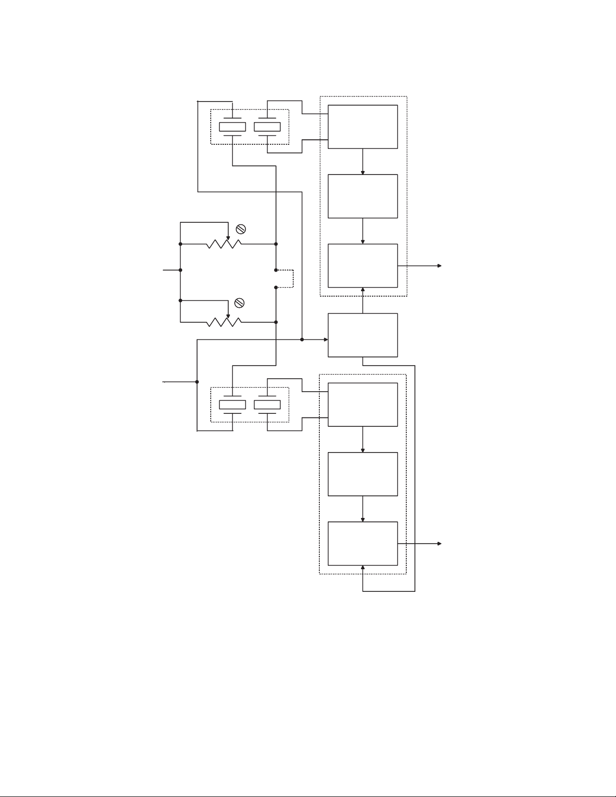
X1
(EMPTY)
4.8 PWA FUNCTIONAL DESCRIPTION
XEMPTY
+ 5 VDC
R2 4
R2 5
XMI TR
XMI TR
RECV R
J MP R 1
RECV R
PREAMP
AM
DET ECTOR
THRESHOLD
DET ECTOR
+ 0 . 5 VDC
REF ERENCE
NET WORK
PREAMP
EMPTY
X2
(BUBBLE)
AM
DET ECTOR
THRESHOLD
DET ECTOR
BUBBLE
+ 0 . 3 VDC
05L03010
Figure 4-8. Bubble Sensor PWA Functional Block Diagram
Technical Service Manual 4 - 39 430-03714-005
Page 66
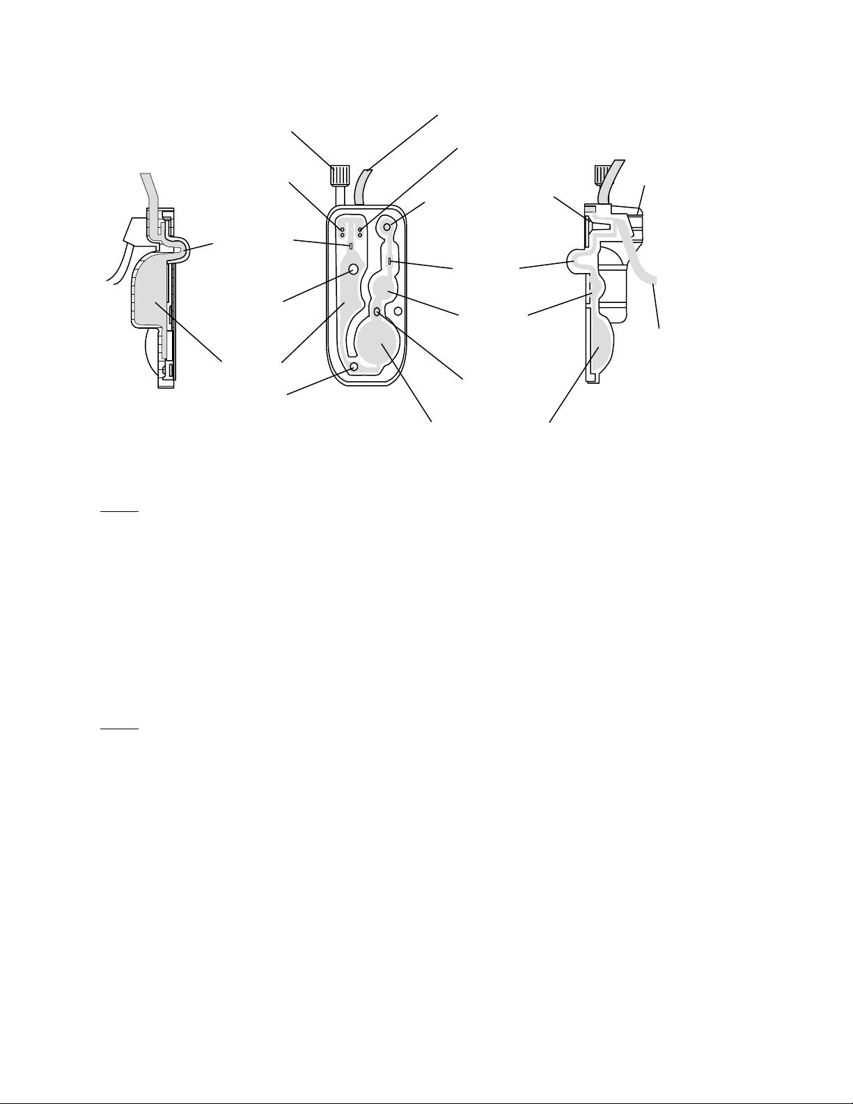
SECTION 4 THEORY OF OPERATION
SECONDARY
(Y-RESEAL OR
LOCKING CAP)
SECONDARY
VALVE
PROXIMAL
AIR-IN-LINE
SENSOR
PROXIMAL
PRESSURE
SENSOR
AIR TRAP
INLET VALVE
REAR VIEW
FROM PRIMARY CONTAINER
PRIMARY VALVE
PRECISION
FLOW REGULATOR
(CONTROL NOT
SHOWN)
DISTAL
AIR-IN-LINE
SENSOR
DISTAL
PRESSURE
SENSOR
OUTLET
VALVE
PUMPING CHAMBER
Figure 4-9. Major Elements of the Dual-Channel Cassette
FINGER
GRIP
OUTLET
TO PATIENT
06G01008
4.8.6.1
PREAMPLIFIER
Potentiometer R24 sets the power level driving the empty X1 crystal, allowing correction
for variations in transducer pair sensitivity. A swept radio frequency (RF) signal (J21, pin
1) from the sensor PWA excites the crystal at its resonant frequency for maximum
ultrasonic output.
The receive crystal is coupled to the common emitter amplifier Q4. Resistors R18, R22,
and R23 bias the collector of Q4 at approximately +2.6 VDC, for maximum linear swing.
Resistors R14, R19, and the emitter resistance of Q4 set the gain to approximately -22.
4.8.6.2
AM AND THRESHOLD DETECTORS
The RF output of the preamplifier is amplitude modulated by the fluid or air in the
ultrasonic path. This signal must be converted to a DC level to permit threshold detection.
Resistors R13 and R15 bias transistor Q2 on the edge of conduction, rectifying the output
of Q4 with only a s mall voltage drop. The 4.7 ms time con stant of resistor R9 and capacitor
C4 hold the peak DC level between RF sweeps for the threshold detector input. Resistors
R24 and R25 are adjusted to give +1.5 VDC in both the proximal and distal channels using
an installed water-filled cassette.
The comparator U1-A compares the DC level from transistor Q2 to a +0.5 VDC reference,
to signal the presence of air by sending the EMPTY (J21, pin 5) line high. If fluid is present,
the input of U1-A is higher than the reference, and the output is low. Resistors R1 and
R2 provide about 20 mV of switching hysteresis for noise immunity. The EMPTY (J21, pin
5) and BUBBLE (J21, pin 6) lines are routed through the sensor PWA to the I/O PWA.
®
430-03714-005 4 - 40 LifeCare
5000 Series
Page 67
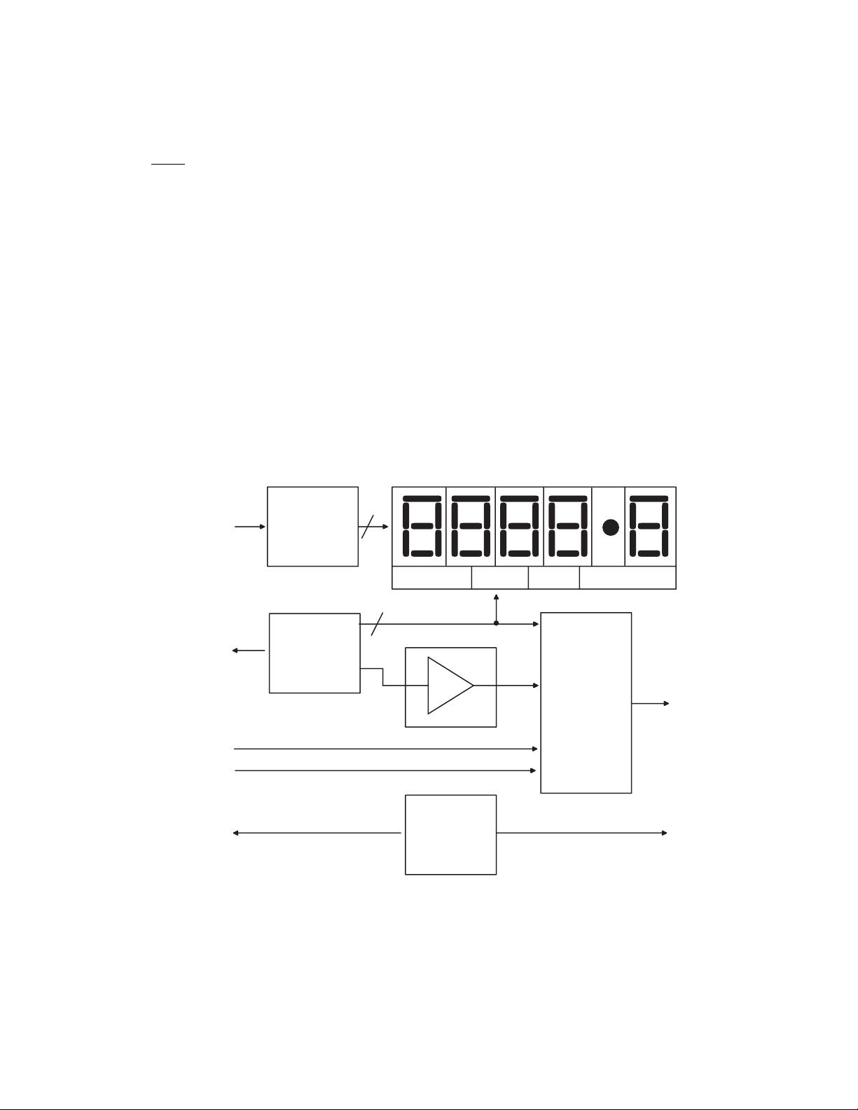
4.8 PWA FUNCTIONAL DESCRIPTION
Resistors R3, R6, and R7 provide the threshold reference network for both the proximal
and the distal channels. The empty reference is +0.5 VDC and the bubble level reference
is +0.3 VDC.
4.8.7
LED DISPLAY PWA
The LED display PWA consists of the following circuitry (Figure 4-10, LED Display PWA
Functional Block Diagram):
❏ Character LEDs and drivers
- Segment and character control
- Display drivers
- Five seven-segment common cathode LEDs
- Three LEDs (AC, battery, and decimal point)
❏ Current sensing amplifier
❏ Analog multiplexer
For a schematic of the LED display PWA, refer to Figure 9-9, LED Display PWA Schematic.
SEGA
THRU
SEGG
CHAR1
THRU
CHAR5
OV P R E F
DROPFB
ELON
SEGMENT
CONTROL
CHARACT ER
CONTROL
8
5
4
23
CHAR1
5
MUXAD
BACKLIGHT
PWR
05L03012
AMP
LCD
BACKLIGHT
CONTROL
MUX
Figure 4-10. LED Display PWA Functional Block Diagram
Technical Service Manual 4 - 41 430-03714-005
Page 68

SECTION 4 THEORY OF OPERATION
4.8.7.1
CHARACTER LEDS AND DRIVERS
The LED characters U1 through U5 are driven by transistor arrays U7, U8, and U9. Digit
drivers are multiplexed through U9, with the MPU refreshing a new digit every three ms.
A custom IC on the main PWA provides the segment drive signals (SEGDA through SEGDP,
P1, pins 1 through 8) and character drive signals (CHAR1 through CHAR5, P1, pins 12
through 16).
When SEGDA through SEGDP goes low, U7 and U8 source current through the resistor
networks RN1 and RN2 to energize the segments of the active character LED. The active
character is selected by the CHAR1 through CHAR5 line that is low, sinking the segment
currents through one of the transistors in U9.
LED 1 and LED 2 are driven by the power supply PWA through LPLEDA (P1, pin 23) and
BPLEDA (P1, pin 24) to indicate AC (mains) line or battery power.
4.8.7.2
CURRENT SENSING AMPLIFIER
Total display current flows to ground through the 1 ohm, current-sensing resistor R3. The
operational amplifier U6-A is configured as an amplifier with a noninverting gain of 11,
through resistor networks RN3 (7,8) and RN3 (8,9) with input dividers RN3 (4,5) and RN3
(5,6) giving 10 times the voltage drop across R3. The output of U6-A is a 10 mV/mA
representation of the current flowing through the active LED character.
4.8.7.3
ANALOG MULTIPLEXER
The collector voltages of U9 and the current sense amplifier output comprise six out of
the eight inputs to multiplexer U10. The remaining inputs are the flow monitor circuit,
and the OVPREF (P1, pin 22) line from the power supply PWA.
The multiplex signals MUX0 through MUX2 (P1, pins 9 through 11), are outputs from the
custom IC on the main PWA. Output MUXAD (P1, pin 20) is delivered to the A/D converter
on the main PWA, allowing the display devices to be tested when the infusion system is
turned on.
Module T1 is a 90 V power supply which generates drive voltage for the LCD screen module
backlight. T1 is energized when the ELON line from the main PWA is high.
4.8.8
FLOW DETECTOR PWA
The flow detector contains two PWAs: a photo emitter PWA, and a photo sensor PWA. As
shown in
DS1 and DS2 on the photo emitter PWA emit narrow beams of infrared light toward the
phototransistors on the photo sensor PWA. The resulting currents are summed at the
sensor output and represent the total infrared energy incident on the transistors Q1, Q2,
and Q3. When a drop falls through the infrared beam, the amount of light incident on the
transistors is reduced, resulting in a corresponding reduction in output current, which
forms the drop signal.
430-03714-005 4 - 42 LifeCare
Figure 4-11, Flow Detector PWAs Schematic Diagram, the flow detector diodes
®
5000 Series
Page 69
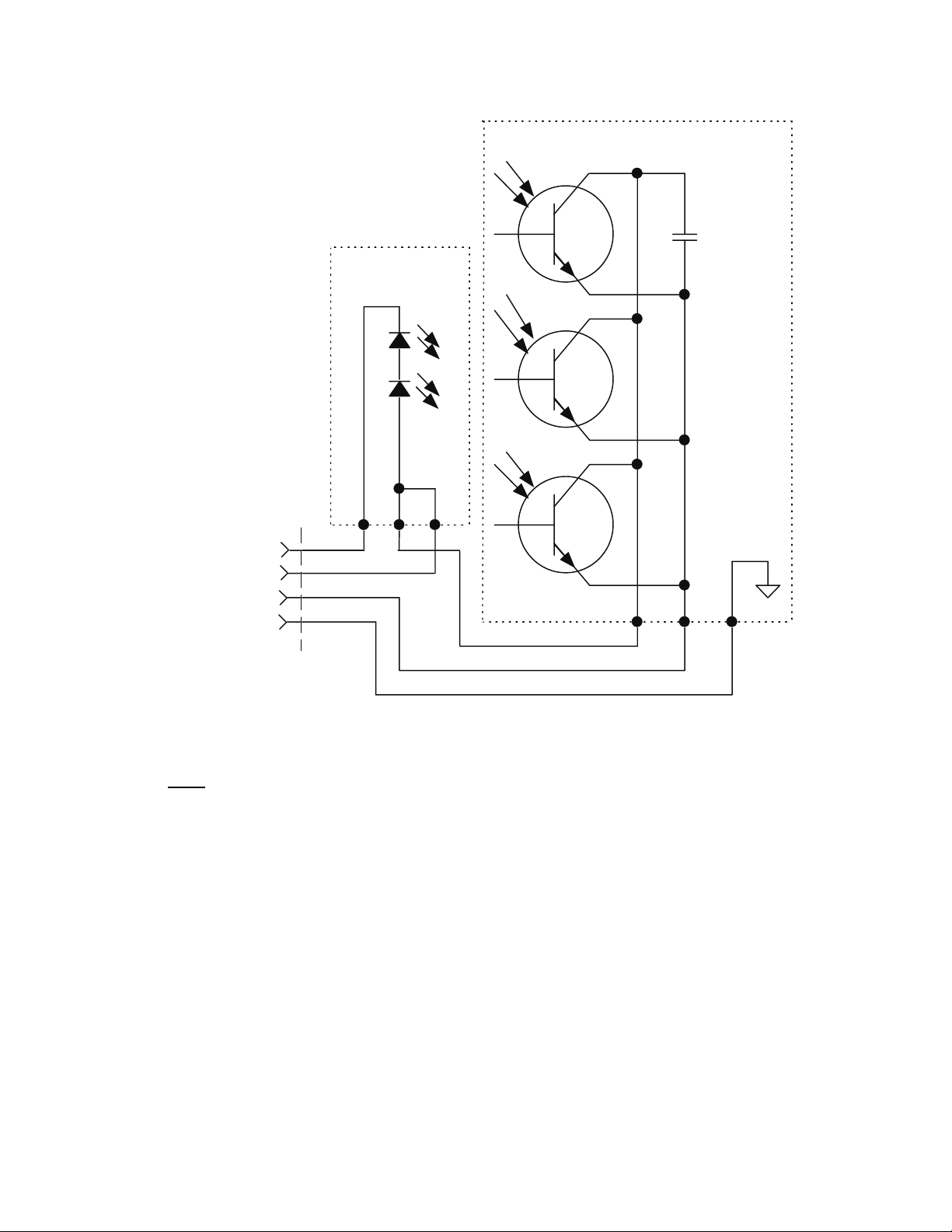
PHOTO EMITTER
PWA
4.8 PWA FUNCTIONAL DESCRIPTION
PHOTO SENSOR PWA
Q1
Q2
DS2
DS1
Q3
ELECTRO-
STATIC
SHIELD GND
1
2
05L03013
LED CATH
+5 VDC
SNSR OUT
GND
4
5
6
WHT
6
1
3
2
RED
3
YEL
GRN
BLK
Figure 4-11. Flow Detector PWAs Schematic Diagram
4.8.9
LCD ASSEMBLY
The LCD assembly is mounted directly behind the LCD window on the infusion system
front panel. The LCD assembly provides a 4-line-by-16-character display for alarm and
status messages. Since the LCD display PWA is an integrated module, no functional block
diagram or schematic is furnished.
The LCD assembly module consists of the 4-line-by-16-character dot matrix display, an
electroluminescent backlight panel, and a PWA containing SMD-integrated circuitry that
performs display interfacing and drive functions. Support circuits on the main PWA and
the display PWA provide contrast control and backlight power, respectively.
Characters are written to and read back from the LCD through line display data (DSPD)0
through DSPD7. LCDRS and LCDWR provide read and write control, respectively. The
read capability allows the system to confirm that data latches in the LCD module are
functioning correctly.
Technical Service Manual 4 - 43 430-03714-005
Page 70
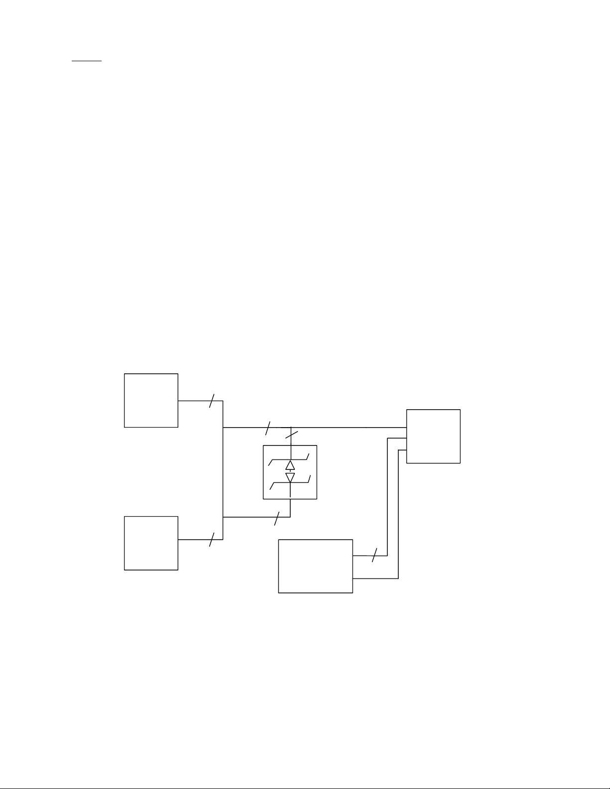
SECTION 4 THEORY OF OPERATION
4.8.10
JUNCTION BOX ASSEMBLY (DATAPORT OPTION)
The junction box assembly permits interconnection and communication between a host
computer and up to 15 DataPort-equipped infusion systems on one channel. Refer to
Section 4.7.2.3, Dataport Interface. The junction box PWA consists of the following circuitry
(4-12, Junction Box PWA Functional Block Diagram, and Figure 9-21, 1.6 Series Junction
Box PWA Schematic):
❏ The main communication lines entering the junction box are TX, communication
(COMM), RX, and CTS. Signals are routed through six-pin modular jacks J1 and J2
and the DB-15 connector P22 in the junction box.
❏ Connectors J1 and J2 are identical and interchangeable. Connector P22 interfaces
with J22 on the I/0 PWA on the back of the infusion system.
❏ Diodes CR1 through CR6 are low-capacity, unidirectional transient voltage
suppressors, two of which perform a bidirectional protection function. The diodes
protect the TX, RX, and CTS signal lines, relative to the COMM signal, from static
discharge. A maximum voltage of 23.6 V is allowed on the transient suppressors
before they conduct. The driver/receiver IC, U5, located on the I/O PWA, tolerates
30 V without sustaining damage.
❏ When properly configured, the DIP switch SW1 assigns a hard ID to each infusion
system. Poles 1 through 4 assign the binary code, and pole 5 is the parity function.
The hard ID circuit is isolated from the COMM lines through digital ground (DGND).
J1
MODULAR
JACK
J2
MODULAR
JACK
4
4
3
CR1 - CR6
TRANSIENT
SUPPRESSOR
1
COMM
4
SW1
5-POLE
DIP SWITCH
5
DGND
Figure 4-12. Junction Box PWA Functional Block Diagram
P22
DB-15
MALE
05L03014
430-03714-005 4 - 44 LifeCare
®
5000 Series
Page 71

4.9 MECHANICAL FUNCTIONAL DESCRIPTION
4.9
MECHANICAL FUNCTIONAL DESCRIPTION
Principal mechanical elements of the infusion system include the following:
❏ Cassette
❏ Three-motor pumping mechanism
❏ Cassette sensor switch
❏ Fluid sensors
❏ Regulator
❏ Interconnect/interface electronics
The following sections detail the cassette and the pumping mechanism. When a cassette
is properly installed, the infusion system performs a 15 second self test to verify the
integrity of internal systems. The properly-installed cassette and closed door activate the
cassette sensor switch, which applies power to the infusion system.
4.9.1
CASSETTE
The infusion system cassette operates on a fluid displacement principle to deliver fluid
volumetrically (
Path in the Cassette). Refer to the system operating manual for a description of the major
cassette functions.
The pumping cycle begins when the outlet valve is opened and the diaphragm is deflected
by the plunger expelling the fluid. At the end of the pumping stroke, the outlet valve is
closed, the inlet opens, and the plunger retracts, allowing fluid to refill the pumping
chamber. After the pumping chamber is filled, the inlet and outlet valves are reversed and
the cycle repeats.
Air detection operates as follows: The cassette contains two chambers separated by an
inlet valve. The upper chamber is an air trap, which receives fluid from the IV container
through either the primary or secondary valve. The upper chamber collects air bubbles
from the IV line and container, and prevents them from entering the pumping chamber.
The air-trap chamber can collect a substantial amount of air before the cassette needs to
be reprimed. The MPU tracks the amount of air collected in the air-trap chamber; if the
limit is reached, it calls for a backprime.
A proximal air-in-line sensor (bubble detector), located between the primary valves and
the air trap, detects air entering the air trap. A proximal air-in-line alarm sounds when a
predetermined amount of air is detected. Similarly, a second air-in-line sensor (bubble
detector), located distal to the pumping chamber, initiates an alarm if a predetermined
amount of air is detected. The distal air-in-line sensor prevents air from reaching the
patient.
4-9, Major Elements of the Dual-Channel Cassette, and Figure 4-1, Fluid
A pressure sensor located distal to the pumping chamber monitors pressure on the distal
side of the cassette. A proximal pressure sensor located above the air trap also monitors
proximal pressure.
Technical Service Manual 4 - 45 430-03714-005
Page 72

SECTION 4 THEORY OF OPERATION
A flow regulator is incorporated in the cassette distal end. This flow regulator can be used
to control flow manually when the cassette is not inserted in the pump.
When the cassette is properly inserted and the door is closed, a mechanism opens the
regulator to allow flow to be controlled by the pump. When the door is opened, the same
mechanism closes the regulator, assuring there is no flow to the patient.
The pumping chamber receives fluid from the air-trap chamber through the inlet valve.
When the diaphragm covering the pumping chamber is deflected by the plunger, the
pumping chamber expels fluid through the outlet valve.
4.9.2
MECHANISM ASSEMBLY
Refer to Figure 4-13, Elements on the Mechanism Assembly. When a cassette is properly
installed and the door is closed, the mechanism assembly turns the cassette [ON/OFF]
switch ON, which activates the plunger. The motors are phased and matched for proper
operation.
During the pumping cycle, the plunger motor drives a nut coupled to a lead screw. The
motor action and screw move the plunger forward, delivering 0.33 ml of fluid per cycle
(0.17 ml for concurrent). The plunger motion synchronizes with the valve motor action to
provide controlled fluid delivery.
The mechanism assembly is a self-contained assembly that consists of the following
components:
❏ Motors and valves (Section 4.9.2.1)
- Primary/secondary valve subassembly
- Inlet/outlet valve subassembly
- Plunger drive subassembly
❏ Cassette door subassembly (Section 4.9.2.2)
❏ Bubble sensor PWA (Section 4.8.6)
❏ Sensor PWA (Section 4.8.5)
4.9.2.1
MOTORS AND VALVES
Pumping action of the mechanism is controlled by three stepper motors. One motor and
associated valve assembly activates either the primary or the secondary valves of the
cassette, depending on command input. The second motor opens or closes the inlet or
outlet valves to control fluid delivery into the cassette chamber. A third motor moves the
plunger, which causes a pumping action that increases pressure to the cassette fluid
pumping chamber.
430-03714-005 4 - 46 LifeCare
®
5000 Series
Page 73
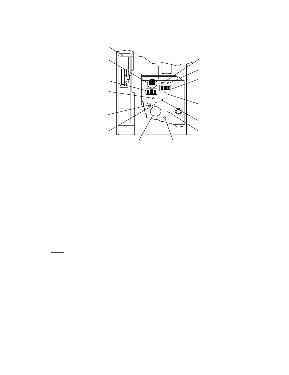
DOOR LATCH
(OPEN POSITION)
4.9 MECHANICAL FUNCTIONAL DESCRIPTION
REGULATOR ACTUATOR
AIR-IN-LINE
DETECTOR (DISTAL)
PRESSURE SENSOR
(DISTAL)
CASSETTE LOCATOR
OUTLET VALVE
PLUNGER
Figure 4-13. Elements on the Mechanism Assembly
4.9.2.2
CASSETTE DOOR SUBASSEMBLY
PRIMARY VALVE
SECONDARY VALVE
(PIGGYBACK)
AIR-IN-LINE
DETECTOR (PROXIMAL)
PROXIMAL PRESSURE
SENSOR
CASSETTE SENSOR
CASSETTE SPRING
LOADER
INLET VALVE
06G01007
The cassette door subassembly consists of the door handle subassembly and the cassette
door holder subassembly. The cassette door holder subassembly is activated by lifting the
door handle, which opens the cassette door holder. The open cassette door holder permits
the installation of a cassette. A mechanism in the mechanism assembly opens the regulator
to allow controlled flow through the cassette. When the door is opened, the regulator closes
to prevent flow to the patient.
4.9.2.3
PRIMARY/SECONDARY VALVE ASSEMBLY
Note: The inlet/outlet valve assembly is similar in design, but opposite in function
to the primary/secondary valve assembly. Because the assemblies are similar, only
the primary/secondary valve assembly description follows.
The primary/secondary valve assembly consists of a stepper motor with attached ball
bearing, flag, two levers, and associated valve pins. The motor is designed to rotate an
eccentrically mounted ball bearing. When positioned at top dead center (home position),
this bearing can rotate 12 steps (90 degrees) left or right. Rotation causes one valve to
open and the other to close. Rotation clockwise from the home position opens the primary
valve and closes the secondary valve.
The flag passes through an interrupter module as it rotates with the shaft of the motor.
Technical Service Manual 4 - 47 430-03714-005
Page 74

SECTION 4 THEORY OF OPERATION
The lever is the connecting link between the eccentrically mounted ball bearing and the
valve pin. The lever also serves as an actuator device in the event of a broken main valve
loading spring. If the spring should break, a small-diameter spring mounted to the bottom
of each lever acts as a safety spring. The safety spring positions the primary lever in the
interrupter module, causing infusion system shutdown and activating alarm code 79 (
see
Table 6-1, Alarm Codes and Corrective Actions).
To determine home position when the infusion system turns on, a pin on the motor
eccentric (combination of shaft, bearing, and cam), comes in contact with a finger attached
to the motor plate.
4.9.2.4
PLUNGER DRIVE ASSEMBLY
The plunger drive assembly consists of the following components:
❏ Stepper motor
❏ Thrust ball bearing
❏ Coupling assembly
❏ Lead screw
❏ Plunger and plunger guide leaf spring
The stepper motor is designed to rotate one and two-thirds revolutions per cycle. Each
rotation of the motor displaces 0.333 ml of fluid. The motor reverses, the plunger returns
to home position, and the cycle repeats for the duration of fluid administration.
The thrust ball bearing rests against the motor mounting base. As the cassette displaces
fluid, the resulting load is absorbed axially by the bearing.
The coupling assembly provides the mechanical linkage for a fixed dead-center location
of the plunger by holding the plunger in true position. A plastic nut is retained within the
coupling assembly, and moves freely on its axis regardless of any misalignment between
the motor and plunger. A wave washer applies a constant spring load against the nut,
confirming the plunger’s fixed location, and allows the nut to move freely in any angular
direction. The coupling assembly also contains a flag, which passes through an interrupter
module, determining the plunger home position. The flag, passing through the interrupter
module, also determines the number of pumping steps.
Each time the infusion system turns on, the motor automatically reverses until home
position is determined. From home position, the pumping cycle starts. As the motor
rotates, the flag passes twice through the interrupter module, the motor stops
momentarily, returns to the home position, and repeats the pumping cycle.
The lead screw converts motor rotation into linear pumping motion. The lead screw is
contained on one end by a nut, and on the other end by a plunger guide leaf spring. The
plunger guide leaf spring and the plunger act as a single unit that cannot be separated.
The plunger guide leaf spring operates in conjunction with the coupling assembly, so the
plunger moves freely in a linear direction.
430-03714-005 4 - 48 LifeCare
®
5000 Series
Page 75

Section 5
MAINTENANCE AND SERVICE TESTS
A complete maintenance program promotes infusion system longevity and trouble-free
instrument operation. Such a program should include routine maintenance, periodic
maintenance inspection, and following any repair procedure, performance verification
testing.
5.1
ROUTINE MAINTENANCE
Routine maintenance consists of basic inspection and cleaning procedures. As a minimum
requirement, inspect and clean the infusion system after each use. In addition, establish
a regular cleaning schedule for the infusion system.
5.1.1
INSPECTING THE INFUSION SYSTEM
Inspect the infusion system periodically for signs of defects such as worn accessories,
broken instrument connections, or damaged cables. In addition, inspect the infusion
system after repair or during cleaning. Replace any damaged or defective external parts.
See
Section 5.2.2, Inspection, for a detailed listing of areas to be inspected.
5.1.2
CLEANING THE INFUSION SYSTEM
The following procedures are designed to maintain the infusion system, sustain system
longevity, and promote trouble-free instrument operation.
Follow hospital protocol for establishing the infusion system cleaning schedule.
WARNING: DISCONNECT THE INFUSION SYSTEM FROM AC POWER
PRIOR TO CLEANING THE INSTRUMENT. FAILURE TO
COMPLY WITH THIS WARNING COULD RESULT IN
ELECTRICAL SHOCK.
CAUTION: Do not immerse the infusion system in liquids. Immersion could damage
the instrument. Do not allow liquids to enter the infusion system electronics
compartment. Do not spray cleaning solutions toward any openings in the infuser.
Technical Service Manual 5 - 1 430-03714-005
Page 76

SECTION 5 MAINTENANCE AND SERVICE TESTS
CAUTION: Certain cleaning and sanitizing compounds may slowly degrade
components made from some plastic materials. Using abrasive cleaners or cleaning
solutions not recommended by Hospira may result in product damage and,
potentially, void the product warranty. Do not use compounds containing
combinations of isopropyl alcohol and dimethyl benzyl ammonium chloride.
CAUTION: Do not use solvents that are harmful to plastic, such as isopropyl alcohol
or acetone. Do not use abrasive cleaners.
CAUTION: To avoid infusion system damage, cleaning solutions should be used only
as directed in
Table 5-1. The disinfecting properties of cleaning solutions vary;
consult the manufacturer for specific information.
1. Clean the cassette door with a soft, lint-free cloth dampened with one of the cleaning
solutions listed in
Table 5-1, Cleaning Solutions, or a mild solution of soapy water.
2. Use a small non-abrasive brush to aid in cleaning the infusion system housing and
subsystem chassis components.
3. To thoroughly clean the cassette receptacle, disengage the cassette door from the
door latch by pressing the door release tab (
see Figure 5-1, Mechanical Elements
Behind Cassette Door).
4. Clean the flow detector with a soft cloth dampened with with an approved cleaning
solution or soapy water.
5. Carefully clean the sensor windows with a cotton swab dipped in cleaning solution
or soapy water. After cleaning, thoroughly dry the windows.
6. Use cotton swabs dampened with an approved cleaning solution to clean the pins.
7. Remove all soap residue with clear water.
Table 5-1. Cleaning Solutions
Cleaning Solution Manufacturer Preparation
Coverage™ HB Steris Corporation Per manufacturer’s recommendation
Dispatch
™
Caltech Industries Per manufacturer’s recommendation
Formula C™ JohnsonDiversey Per manufacturer’s recommendation
Manu-Klenz
Precise
Sporicidin
®
Steris Corporation Per manufacturer’s recommendation
™
®
Caltech Industries Per manufacturer’s recommendation
Sporicidin International Per manufacturer’s recommendation
Super Edisonite S. M. Edison Chemical Co. Per manufacturer’s recommendation
Household bleach Various Per hospital procedures; do not exceed
one part bleach in ten parts water
430-03714-005 5 - 2 LifeCare
®
5000 Series
Page 77
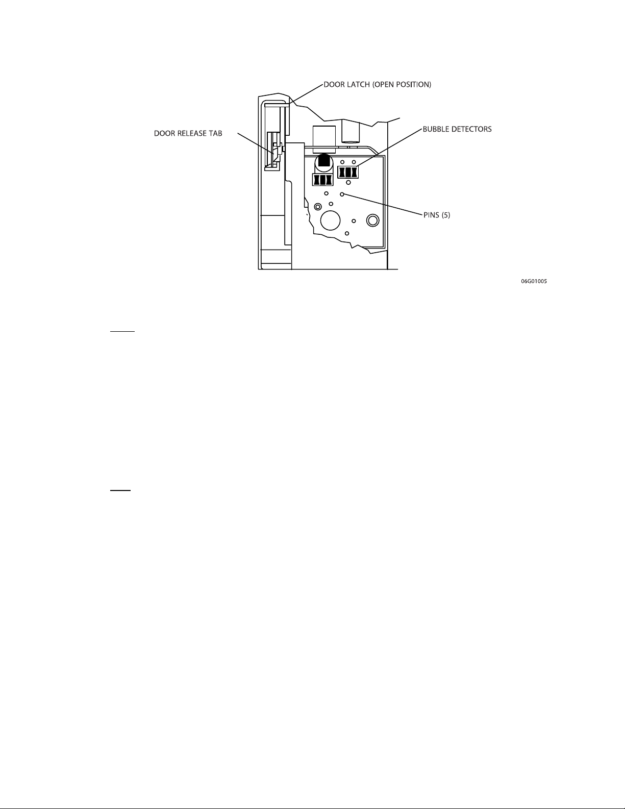
5.2 PERFORMANCE VERIFICATION TEST
Figure 5-1. Mechanical Elements Behind Cassette Door
5.1.3
SANITIZING THE INFUSION SYSTEM
Sanitize the external surfaces of the infusion system using a cleaning solution listed in
Table 5-1, Cleaning Solutions.
Note: Not all cleaning solutions are sanitizers. Check product labeling.
CAUTION: Do not sterilize the infusion system using heat, steam, ethylene oxide
(ETO), or radiation. These methods may cause the instrument to malfunction.
5.2
PERFORMANCE VERIFICATION TEST
The performance verification test (PVT) consists of the tests described in the following
sections. The PVT can be used for diagnostic purposes during the troubleshooting of a
malfunctioning infusion system. The PVT should be used for performance verification
before an infusion system is placed back in service after repair. If any malfunction is
detected as a result of the PVT, refer to
Table 6-3, Troubleshooting with the PVT.
Note: The PVT must be performed exactly as described in this manual to assure
effective and reliable product evaluation information.
Technical Service Manual 5 - 3 430-03714-005
Page 78

SECTION 5 MAINTENANCE AND SERVICE TESTS
5.2.1
EQUIPMENT AND MATERIALS REQUIRED
The equipment and materials or equivalents required to perform the PVT are as follows:
❏ Safety analyzer (Fluke Biomedical 232D)
❏ Digital Pressure Meter (DPM), Fluke® Biomedical DPM3
❏ Blunt Cannula, List No. 11302 or 21-gauge needle, List No. 4492 (optional)
❏ Nurse-call test cable or equivalent 1/4 inch phone jack to banana plug, P/N
561-88416-001
❏ Three-way stopcock, latex-free (List No. 3233-01, or equivalent)
❏ Reflux valve P/N 711-38272-001 (optional)
❏ 470 ohm/100 microfarad, resistor/capacitor parallel network, P/N 561-88419-001
❏ Digital multimeter (DMM), Fluke Biomedical 8012A
❏ Two containers of sterile water, List No. 7973-08, or tap water
❏ IV sets, List Nos. 6426-02 and 3047-01 (optional)
❏ Primary macro set plus matching secondary macro set
❏ 25 ml graduated cylinder (0.2 graduations)
❏ No. 2 Phillips screwdriver
❏ Hex nutdriver set
❏ Stopwatch
❏ Recirculating set, List No. 6426-02, with proximal sensor bulb tips removed from
cassette, and marked EMPTY on the cassette
❏ Recirculating set, List No. 6426-02, with distal sensor bulb tips removed from
cassette, and marked AIR on the cassette
❏ PCXT or compatible computer (to perform PVT on infusion systems with DataPort)
❏ Infusion system DataPort to PC cable (to perform PVT on infusion systems with
DataPort)
❏ Bubble sensor location fixture, P/N 561-81402-001
❏ Bubble sensor location calibration block (calibration block), P/N 561-81402-006
Note: The bubble sensor location fixture and calibration block are required
only when performing the bubble sensor location test.
5.2.2
INSPECTION
Inspect the infusion system periodically for signs of defects such as worn accessories or
damaged cables. Also, inspect the infusion system after repair or during cleaning. Replace
any damaged or defective external parts.
Inspect the following for missing or damaged parts and for cosmetic defects:
❏ All cords
❏ Case
❏ Pole clamp and pad
❏ All switches
®
430-03714-005 5 - 4 LifeCare
5000 Series
Page 79

5.2 PERFORMANCE VERIFICATION TEST
❏ Accessory jacks
❏ Faceplate
❏ Pressure pads (feet)
❏ Velcro® strap
❏ Minipole and clutch
❏ Door assembly (open and unlatch door; check valve pins and air sensor behind door.
❏ Valve pins should move freely in the guide holes. Clean as necessary
❏ Flow detector (as applicable)
❏ Junction box (as applicable)
5.2.3
START-UP TEST
WARNING: DO NOT CONNECT A PATIENT TO THE INFUSION SYSTEM
DURING DEVICE TESTING.
The following tests are conducted with the infusion system in the MACRO SECONDARY
MODE (dual channel, single dose). When the infusion system is in this mode, the LCD
screen displays: LIFECARE 5000 DUAL CHANNEL. Before starting the PVT, note the
configuration of the DIP switches and place the infusion system in the MACRO
SECONDARY MODE as necessary. Refer to
information on DIP switch settings for the desired mode. See also Figure 1-2, DIP Switch
Settings for Each Delivery Mode. At the conclusion of the PVT, reset DIP switches to the
previous settings.
Section 1.10, Setting the Delivery Mode, for
Note: If testing in MICRO SECONDARY MODE, the maximum delivery rate is 99.9
ml/hr.
Note: For all testing, the vertical distance from the top of the fluid in the flexible
container to midline of the cassette must be 18 ± 6 inches (46 ±
Figure 5-3, Recirculating Set Test Setup.
To perform the start-up test, proceed as follows:
1. Insert the primed IV set with 21-gauge needle attached to the distal line end, into
the door. Close the door and verify the red battery power symbol illuminates.
2. Connect infusion system to an AC (mains) outlet and verify the green AC (mains)
power symbol illuminates.
15 cm) as shown in
Note: Complete the remainder of the PVT with the infusion system connected
to AC (mains) power, except as specified.
Technical Service Manual 5 - 5 430-03714-005
Page 80

SECTION 5 MAINTENANCE AND SERVICE TESTS
3. To verify that all touchswitches emit one short tone or flutter, press each
touchswitch in sequence as follows:
[START]
[RESET]
[REVIEW/CHANGE]
[SILENCE/NO]
[T]
[S]
[YES/ENTER]
[CLEAR]
4. Press all touchswitches again except [START] and [CLEAR] in same sequence as
described in Step 3; verify that no tones sound. Press [CLEAR] and listen for flutter.
5. Press all touchswitches again as described in Step 3; listen for tone or flutter.
6. Optional: Open and reclose door; observe that all LEDs and the LED decimal point
illuminate immediately. When SELF TEST:OK prompt appears, press [REVIEW] to
view software revision. Press [REVIEW] again to view alarm history.)
5.2.4
BUBBLE SENSOR LOCATION TEST
To perform the bubble sensor location test, refer to Figure 5-2, Gauge Dial Indicator.
Standardize the gauge of the bubble sensor location fixture, as follows:
1. Place calibration block (boss end) of bubble sensor location fixture over each contact
pin, holding the block flush to the base of fixture.
2. Check gauge dial indicators for 0 reading on outer scale and 1 inner revolution
indicator. Adjust bezel to 0 as necessary by loosening bezel clamp. Retighten after
adjustment is made.
After standardizing the fixture, perform the bubble sensor location test as follows:
1. Insert bubble sensor location fixture in cassette door and close door.
2. Verify that both dial indicators read 1 revolution ± 0.010.
3. Open cassette door and remove fixture.
430-03714-005 5 - 6 LifeCare
®
5000 Series
Page 81

5.2 PERFORMANCE VERIFICATION TEST
Figure 5-2. Gauge Dial Indicator
5.2.5
NURSE-CALL TEST
Note: The following test may be bypassed if the nurse-call function is not used.
To perform the nurse-call test, attach the nurse-call cable, then proceed as follows:
1. Set primary delivery rate to 400 ml/hr and primary dose limit to 1 ml.
2. Connect DMM to nurse-call cable.
3. Press [START] and verify pumping action.
4. After DOSE END and KVO appear on the LCD screen, observe a short circuit on
DMM (approximately 1 ohm on 0 to 100
5.2.6
EMPTY CONTAINER TEST
To perform the empty container test proceed as follows:
1. Insert the special cassette marked EMPTY, with the proximal bubble sensor bulb
tips removed and close the door (
Figure 5-4, Infusion System Cassettes with Bubble Sensor Tips Removed).
2. Set RATE to 400 ml/hr and press [ENTER].
3. Set DOSE LIMIT to 10 ml and press [ENTER].
4. Press [NO] in response to SET SECONDARY.
5. Press [START] and confirm that pumping occurs. Confirm that an alarm sounds.
Within 30 seconds, confirm the following message appears on the LCD screen:
STOPPED AIR IN PROXIMAL LINE PRESS RESET.
6. Open door and remove cassette.
see Figure 5-3, Recirculating Set Test Setup, and
Ω scale).
Technical Service Manual 5 - 7 430-03714-005
Page 82
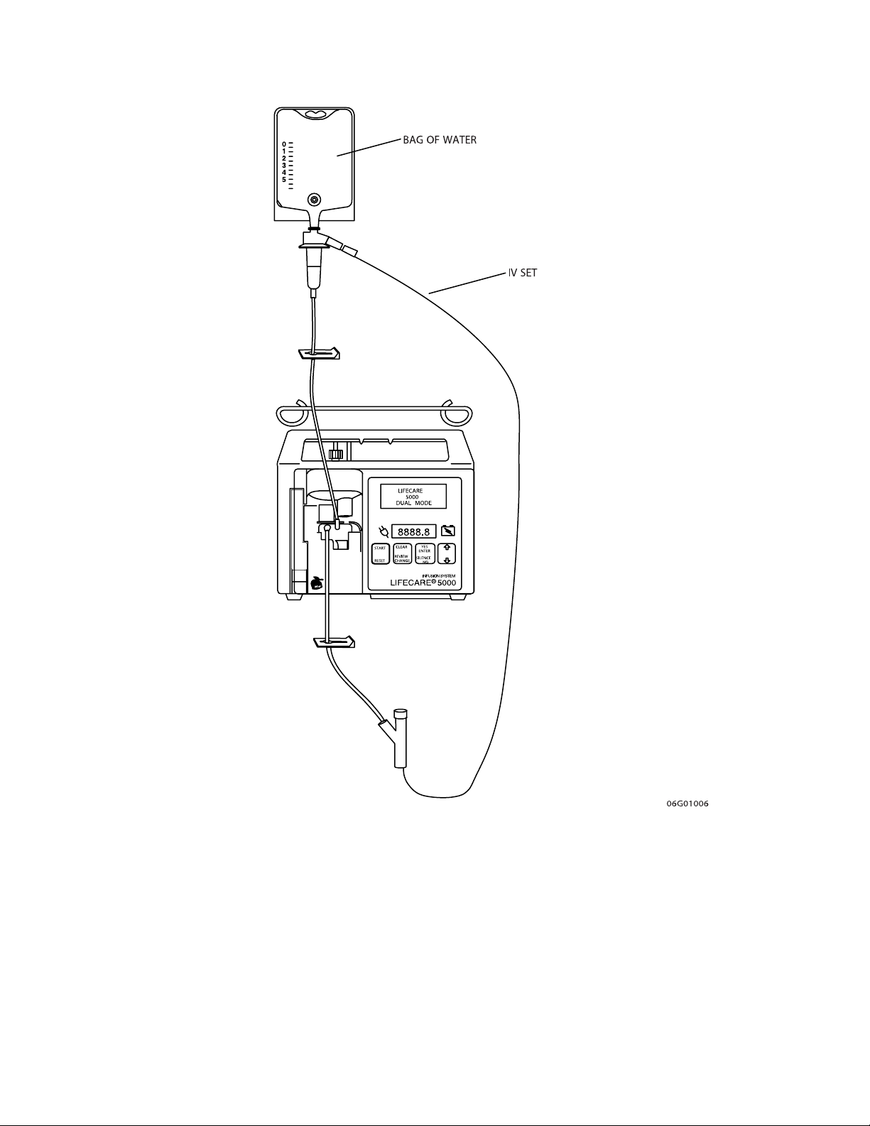
SECTION 5 MAINTENANCE AND SERVICE TESTS
Figure 5-3. Recirculating Set Test Setup
430-03714-005 5 - 8 LifeCare
®
5000 Series
Page 83
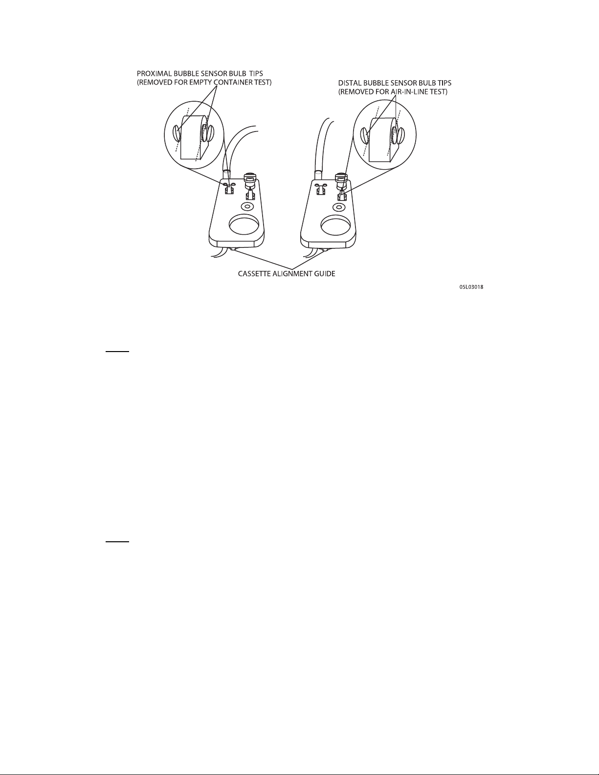
5.2 PERFORMANCE VERIFICATION TEST
Figure 5-4. Infusion System Cassettes with Bubble Sensor Tips Removed
5.2.7
AIR-IN-LINE TEST
To perform the air-in-line test, proceed as follows:
1. Insert the recirculating set with cassette marked AIR, and with distal bubble sensor
bulb tips removed (
2. Close the cassette door and press [YES] in response to SAVE SETTINGS.
3. Press [YES] in response to FINISH PRIMARY DOSE; press [START].
4. Verify that an alarm sounds. Within 30 seconds, verify the following message
appears on the LCD screen: STOPPED AIR IN DISTAL LINE PRESS RESET.
5. Press [RESET]; open and close door. Press [NO] in response to SAVE SETTINGS.
Press [NO] in response to RETAIN VOLUME.
see Figure 5-3, and Figure 5-4).
5.2.8
CONCURRENT DELIVERY TEST
To perform the concurrent delivery test, proceed as follows:
1. Set operating parameters as follows:
- Primary delivery rate: 400 ml/hr
- Primary dose limit: 100 ml
- Press [YES] in response to SET SECONDARY
- Press [YES] in response to SET CONCURRENT DELIVERY
- Secondary delivery rate: 200 ml/hr
- Secondary dose limit: 50 ml
Technical Service Manual 5 - 9 430-03714-005
Page 84

SECTION 5 MAINTENANCE AND SERVICE TESTS
2. Press [START] and verify the LCD screen displays: PUMPING-CONCURRENT.
3. Verify that pumping occurs alarm-free for one minute.
5.2.9
DELIVERY ACCURACY TESTING
Note: Accuracy testing is for informational purposes only, and is not to be used as
a re-release test. If there is any concern as to infusion system accuracy, return the
infusion system to Hospira.
5.2.9.1
DELIVERY ACCURACY TEST (MACRO)
To perform the delivery accuracy test in macro secondary mode, proceed as follows:
1. Insert needle or adapter of primed secondary set into cassette secondary inlet.
2. Confirm the infusion system DIP switches are set for MACRO SECONDARY MODE
(dual channel, single dose), as described in
operating parameters as follows:
- Primary delivery rate: 400 ml/hr Primary dose limit: 10 ml. Press [YES] in response
to SET SECONDARY.
- Press [NO] in response to CONCURRENT DELIVERY
- Secondary delivery rate: 400 ml/hr
- Secondary dose limit: 10 ml
3. Press [YES] in response to CALL BACK AT SECONDARY DOSE END. Press [NO] in
response to CONTINUE SECONDARY AT DOSE END. Press [NO] in response to
DELIVER SECONDARY OVERFILL.
4. Place distal Cannula or needle into graduated cylinder and press [START].
5. If flow detector is used, attach to primary drip chamber and connect cable to port
on back of infusion system.
6. Verify pumping action.
7. At end of secondary, verify the following message appears on the LCD screen: SEC
DOSE END PUMPING PRIMARY PRESS SILENCE
8. Press [SILENCE]. In response to REPEAT SECONDARY, press [NO].
9. If testing flow detector, verify that infusion system operation is alarm free during
primary delivery.
10. After DOSE END and KVO appear on the LCD screen, a flashing 1 appears on the
LED display, and an alarm sounds, press [RESET].
11. To observe total volume, press [YES] in response to REPEAT PRIMARY. Press
[CLEAR]; observe total volume of 20 ml. Press [YES] to clear. The volume in the
graduated cylinder should be 20 ml ± 1 ml.
Section 5.2.3, Start-Up Test. Set
Note: If the infusion system fails to deliver properly, reprime cassette and repeat test.
If the infusion system again fails to deliver properly,
430-03714-005 5 - 10 LifeCare
contact Hospira.
®
5000 Series
Page 85

5.2 PERFORMANCE VERIFICATION TEST
5.2.9.2
DELIVERY ACCURACY TEST (MICRO)
Note: This test need only be performed if the DIP switches were set to MICRO
SECONDARY MODE on the device when it was received.
To perform the delivery accuracy test in micro secondary mode, proceed as follows:
1. Insert needle or adapter of primed secondary set into cassette secondary inlet.
2. Set the infusion system DIP switches to MICRO SECONDARY MODE (dual channel,
single dose), as described in
as follows:
- Primary delivery rate: 99.9 ml/hr Primary dose limit: 10 ml. Press [YES] in response
to SET SECONDARY.
- Press [NO] in response to CONCURRENT DELIVERY
- Secondary delivery rate: 99.9 ml/hr
- Secondary dose limit: 10 ml
3. Press [NO] in response to SECONDARY OVERFILL.
4. Place distal Cannula or needle into cylinder graduate and press [START].
5. Verify pumping action.
6. After DOSE END and KVO appear on the LCD screen display, a flashing 1 appears
on the LED display and an alarm sounds. Press [RESET].
7. To observe total volume, press [YES] in response to REPEAT PRIMARY, then press
[CLEAR] and observe total volume of 20 ml. Press [YES] to clear. The volume in the
graduated cylinder should be between 19 and 21 ml.
8. Disconnect infusion system from AC (mains) power.
9. Open door and start stopwatch; if battery symbol remains illuminated for more than
10 seconds, memory reserve is functional.
10. Reconnect infusion system to AC (mains) power.
11. Close door. At end of self test, clear all operating parameters by pressing [SILENCE/
NO] and [YES/ENTER].
12. Set the infusion system DIP switches to MACRO SECONDARY MODE (dual channel
single dose), as described in
Section 5.2.3. Set the remaining operating parameters
Section 5.2.3.
Note: If the infusion system fails to deliver properly, reprime cassette and repeat test.
If the infusion system again fails to deliver properly,
Section 6.1, Technical Assistance).
5.2.10
PRESSURE SENSOR TEST
To perform the pressure sensor test, proceed as follows:
1. Set operating parameters as follows:
- Primary delivery rate: 40 ml/hr
- Primary dose limit: 100 ml. Press [NO] in response to SET SECONDARY
- Occlusion pressure: 4 psig (27.6 kPa) (accessed by pressing the [REVIEW/
CHANGE] touchswitch)
Technical Service Manual 5 - 11 430-03714-005
contact Hospira (see
Page 86

SECTION 5 MAINTENANCE AND SERVICE TESTS
2. Connect distal tubing to DPM through a three-way stopcock, as shown in Figure 5-5,
Pressure Sensor Test Setup. A reflux valve between the stopcock and the meter may
be used to prevent moisture from entering the meter.
Note: Height of DPM must be 0 ± 6 inches (0 ± 15 cm) from the midline of the
cassette.
3. Open stopcock to air.
4. Press [START] and allow infusion system to stabilize for at least one minute.
5. Set the stopcock to measure pressure.
6. Press [REVIEW/CHANGE] until the LCD screen displays the pressure according to
the infusion system under test.
7. Verify STOPPED DISTAL LINE OCCLUSION alarm status on LCD screen.
8. DPM should display 4.0 ± 1.0 psig (27.6 ± 6.9 kPa).
9. While the infusion system is in occlusion, turn the audible alarm switch to all three
positions and make certain that audible levels operate correctly.
10. Press [RESET].
11. Set infusion system pressure to 8 psig (55 kPa) and repeat Step 4 through Step 10
(omitting Step 11). At occlusion, the DPM should display 8 ± 1.5 psig (55.1 ± 10.3
kPa).
12. Remove the distal tubing from the stopcock. Place distal tubing in waste receptacle
or recirculate.
13. Open and close door; press [NO] to save settings.
14. Set operating parameters as follows:
- Primary delivery rate: 200 ml/hr
Primary dose limit: 10 ml. Press [YES] in response to SET SECONDARY.
- Press [YES] in response to CONCURRENT.
- Secondary delivery rate: 200 ml/hr
- Secondary dose limit: 10 ml.
- Press [NO] in response to CALLBACK AT SECONDARY DOSE END.
- Press [NO] in response to DELIVER SECONDARY OVERFILL
15. Press [START] and allow system to stabilize for at least one minute.
16. After a minimum of two cycles, clamp proximal primary tubing just below drip
chamber. Verify the LCD screen displays: STOPPED PROX. OCCLUSION PRIMARY,
and an alarm sounds within three pumping cycles.
17. Press [RESET] and unclamp the tubing; open the door.
430-03714-005 5 - 12 LifeCare
®
5000 Series
Page 87
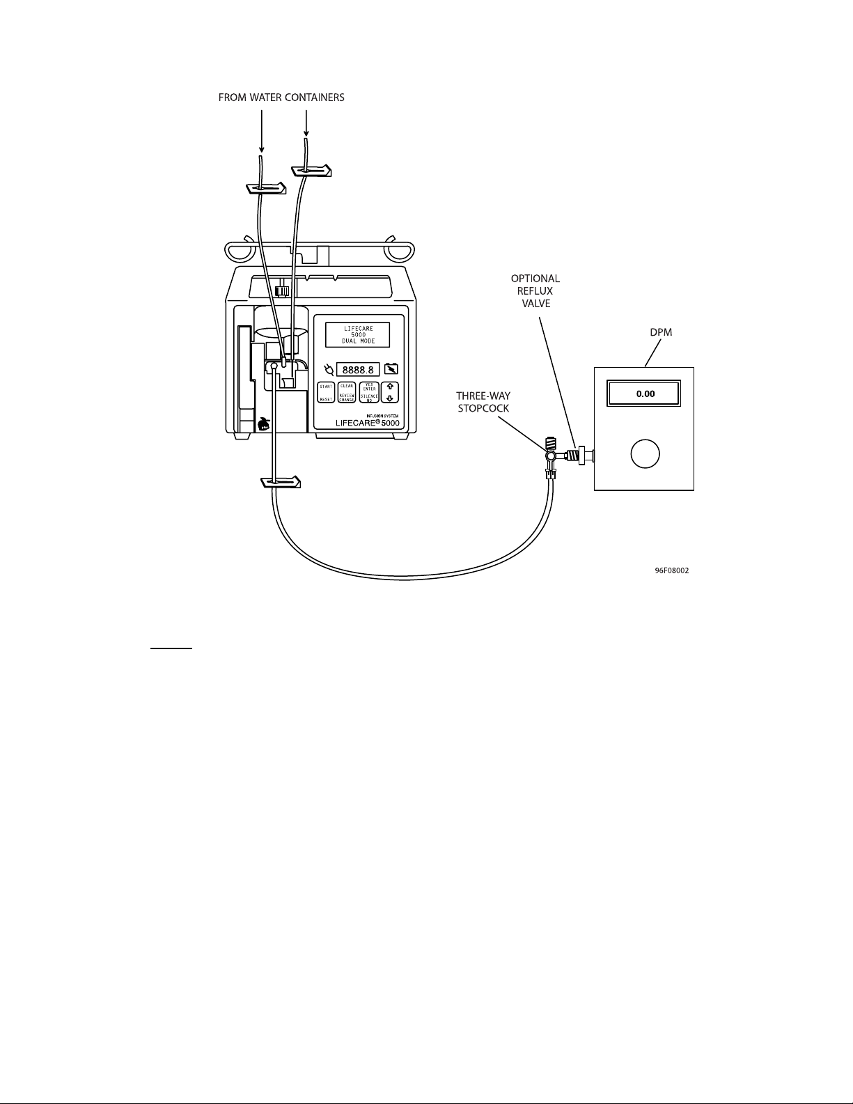
5.2 PERFORMANCE VERIFICATION TEST
Figure 5-5. Pressure Sensor Test Setup
5.2.11
ELECTRICAL SAFETY TEST
Note: The electrical safety test must be performed in accordance with the instructions
contained in the safety analyzer user’s guide.
To perform the electrical safety test, proceed as follows:
1. Connect the AC power cord to the safety analyzer.
2. Connect the safety analyzer ground lead to the device equipotential post.
3. Test the enclosure and earth leakage currents under normal and single fault
conditions. See Table 5-3 for electrical safety measurements.
4. Measure the resistance between the AC connector ground lug and exposed metal
parts (see Table 5-3).
Technical Service Manual 5 - 13 430-03714-005
Page 88

SECTION 5 MAINTENANCE AND SERVICE TESTS
Note: The door hinge is not grounded.
Table 5-2. Electrical Safety Measurements
Measurement Not to Exceed
Enclosure leakage current normal condition (ground intact) 0.1 mA
Enclosure leakage current (open ground) 0.5 mA
Earth leakage current (ground intact) 0.5 mA
Earth leakage current (open ground) 1 mA
Chassis ground resistance 0.2 Ω
5.2.12
DATAPORT COMMUNICATION TEST
Note: The following procedure may be bypassed if the DataPort communications
feature is not used.
The following program, written in BASIC, tests the DataPort communications hardware of
the infusion system.
To perform the DataPort communication test, connect the DataPort host computer directly
to the infusion system DataPort connector and run the following program. See
DataPort Accessory Cable Schematics, and Table 7-1, Accessories for LifeCare 5000 Infusion
Systems, for proper hardware connections.
10 REM ***************************************************************
20 REM ***
30 REM * Program: LCTEST.BAS REV:1.01
40 REM * Description:
50 REM This program will test the hardware of the LC5000
60 REM DATAPORT system. A single packet will be sent to the
70 REM pump and one will be expected in reply. The CRC is
80 REM pre-calculated. This program will communicate with only
Figure 7-12,
90 REM one pump--communication with multiple pumps on a single
100 REM bus line will not function with this program.
110 REM * Interpreter : IBM BASIC Version 2.0
120 REM ***
130 REM ***************************************************************
430-03714-005 5 - 14 LifeCare
®
5000 Series
Page 89

140 REM *** Beginning of program.
150 REM *** Clear computer screen.
160 CLS
170 REM *** Indicate “no packets received”.
180 LCSTR$ = ““
190 LCLEN = 0
200 REM *** If error then report failure of computer port.
210 ON ERROR GOTO 450
220 REM *** Activate communication port on the computer:
230 REM *** port = 1, baud rate = 1200, parity = none,
240 REM *** data bits = 8, stop bits =1.
250 COM(1) ON
260 ON COM(1) GOSUB 530
5.2 PERFORMANCE VERIFICATION TEST
270 OPEN “COM1:1200,N,8,1” AS #1
280 REM *** Send packet to pump:
290 REM *** Flush and ask for status from Hard-ID 0.
300 PRINT #1,CHR$(3);
310 PRINT #1,”T@0;ISTA;2FAD”
320 REM *** Wait for a reply packet from pump.
321 REM *** To reduce the waiting period for the reply packet
322 REM *** to be sent from the pump to the PC, the loop
323 REM *** counter (25000) in line 330 may be reduced as
324 REM *** required to a minimum of 1500.
330 FOR I=I TO 25000
340 NEXT
350 REM *** Test for a received packet. If received packet is empty
360 REM *** then test FAILS. Otherwise, test PASSes and the received
370 REM *** packet is printed.
380 REM ***
390 IF LCLEN = 1 THEN GOTO 400 ELSE GOTO 420
400 PRINT “** TEST PASSED, received packet:”;LCSTR$
410 GOTO 500
420 PRINT “** TEST FAILED, no communication from pump.”
Technical Service Manual 5 - 15 430-03714-005
Page 90

SECTION 5 MAINTENANCE AND SERVICE TESTS
430 GOTO 500
440 REM *** Communication port error.
450 PRINT CHR$(13);CHR$(13);CHR$(13)
460 PRINT “Communication ERROR on COM1 port--check cable connections.”
470 GOTO 510
480 REM *** Close communication port.
490 COM(1) OFF
500 CLOSE
510 END
520 REM *** Receive the packet.
530 INPUT #1,LCSTR$
540 COM(1) OFF
550 LCLEN = 1
560 RETURN
570 REM *** End of program.
If TEST PASSED is displayed at the end of the program, the infusion system
communication hardware and software are functioning properly. If TEST FAILED is
displayed at the end of the program, re-enter program. If TEST FAILED is still displayed,
refer to the DataPort malfunctions in
DataPort Only), or contact Hospira.
Table 6-2, Troubleshooting DataPort Systems (1.6
5.2.13
END OF PERFORMANCE VERIFICATION TEST
At the completion of the PVT, proceed as follows:
1. Clear dose history. Open and close door. When SAVE SETTINGS appears on the
LCD screen, press the [NO] touchswitch.
2. If all tests are successful, return infusion system to service. If any of the tests fail,
refer to
3. Reset DIP switches to previous configuration.
Section 6, Troubleshooting, or contact Hospira.
5.3
PERIODIC MAINTENANCE INSPECTION
Periodic maintenance inspections should be performed per hospital procedures for
compliance to accreditation requirements. It is recommended that JCAHO and/or hospital
protocol be followed for establishing an infusion system periodic maintenance inspection
schedule. To perform the periodic maintenance inspection, complete the performance
verification test in
430-03714-005 5 - 16 LifeCare
Section 5.2.
®
5000 Series
Page 91

5.4 BATTERY OPERATION OVERVIEW
5.4
BATTERY OPERATION OVERVIEW
The infusion system is intended to operate on battery power on an exception basis only,
such as emergency backup or temporary portable operation. Examples of emergency
backup include AC (mains) power failure or inadvertent disconnection of the AC (mains)
power cord. An instance of temporary portable operation includes patient transfer from
one location to another.
The infusion system should be connected to AC (mains) power whenever possible to allow
the battery to remain fully charged. The infusion system line power indicator disappears
and the BATTERY legend appears when the infusion system is operating on battery power.
Factors that most commonly affect battery life are the depth and frequency of discharge
and the length of the recharge period. As a general rule, the more often the battery is
discharged and recharged the sooner it will need replacement. The primary cause of
damage is leaving the battery in a less than fully charged state for any period of time.
Battery damage can occur in a matter of hours and cause a permanent loss of battery
capacity. The amount of lost capacity depends on the degree of discharge, the storage
temperature, and the length of time the battery was stored in a discharged state.
Note: A permanently damaged battery cannot be recharged to full capacity.
When the battery discharges below the acceptable level while the infusion system is
operating, the alarm sounds and the LOW BATTERY message displays. Although it is not
recommended to continue operating the infusion system on battery power at this point,
the battery will continue providing power until discharged. At this point, the infusion
system enters the battery discharged mode and operation ceases.
CAUTION: As soon as the LOW BATTERY alarm occurs, connect the infusion system
to AC (mains) power.
Recharging occurs any time the infusion system is connected to AC (mains) power. It is
recommended that the infusion system be connected to AC (mains) power whenever
practical to maximize available battery charge during transport or ambulation. The power
switch does not have to be on for the battery to recharge. Recharging while the infusion
system is operating is rate dependent.
The infusion system should be operated on battery power for six continuous hours at least
once every six months for optimum battery performance and life.
5.4.1
BATTERY CHARGER CURRENT TEST
To perform the battery charger test, proceed as follows:
1. Clear all rates and volumes then disconnect the infusion system from AC (mains)
power.
2. Open the door and confirm that in approximately 30 seconds, the LCD screen dims
completely and the battery symbol deactivates.
3. Remove cassette and close door.
Technical Service Manual 5 - 17 430-03714-005
Page 92

SECTION 5 MAINTENANCE AND SERVICE TESTS
4. Remove battery pack cover and disconnect battery pack from charger by
disconnecting battery cable (
Section 7.2.2).
5. Connect resistor-capacitor network to charger connector at one end and to DMM
at other end.
6. Connect infusion system to AC (mains) power and measure voltage across network
with DMM set to 0 to 100 voltage scale. DMM should display 13
2 VDC.
7. Disconnect resistor-capacitor network and AC (mains) power.
8. Reconnect battery pack and replace battery pack cover.
430-03714-005 5 - 18 LifeCare
®
5000 Series
Page 93

Section 6
TROUBLESHOOTING
This section contains information on obtaining technical assistance, and alarm messages
and error codes for the LifeCare 5000 infusion system. All alarm and malfunction codes
detailed in this section can be monitored by a host computer connected to infusion systems
with the DataPort communications feature.
6.1
TECHNICAL ASSISTANCE
For technical assistance, product return authorization, and to order parts, accessories,
or manuals within the United States,
Send all authorized, prepaid returns within the United States to the following address:
Technical Support Operations
contact Hospira Technical Support Operations.
1-800-241-4002
Hospira, Inc.
755 Jarvis Drive
Morgan Hill, CA 95037
For technical assistance, product return authorization, and to order parts, accessories or
manuals from outside the United States, contact the nearest Hospira sales office.
6.2
AUDIBLE ALARMS
The infusion system alerts the user to an abnormal condition with an audible alarm. An
audible alarm sounds either a continuous alarm tone, indicating a power failure, or a tone
sequence of short-long-short-long. These short-long-short-long tones indicate the infusion
system is in the alarm state (
automatically enters an alarm state whenever it detects an alarm condition. Infusion is
prohibited during all audible alarm conditions unless otherwise indicated.
The following sections briefly describe alarm messages, alarm conditions, and obtaining
an alarm history for the LifeCare 5000 infusion system.
see Section 4.2, Alarm Conditions). The infusion system
Technical Service Manual 6 - 1 430-03714-005
Page 94

SECTION 6 TROUBLESHOOTING
6.2.1
ALARM MESSAGES
Under certain alarm conditions, the infusion system stops operating, generates an audible
alarm, displays an alarm code, and an alarm message on the LCD screen. Alarm codes
06, 07, 08, 09, 0A, 12, 13, 14, and 15 display an initial alarm message on the LCD screen,
followed by a secondary alarm message. There are two categories of alarm codes: codes
that can be cleared by the operator and codes that require the assistance of qualified
service personnel.
Table 6-1, Alarm Codes and Corrective Actions, lists alarm codes, LCD screen messages,
possible causes, corrective actions, and DataPort codes. Alarm codes listed in Table 6-1
are hexadecimal in value from 00(16) to FF(16). The LCD screen message column
differentiates alarm codes as operator-cleared messages or malfunction codes requiring
the assistance of qualified service personnel. Operator alarm messages are corrected using
corrective actions described in the system operating manual. DataPort codes apply only
to 1.6 series infusion systems with DataPort.
CAUTION: If excessive alarms occur, contact Hospira.
Note: (*) indicates international devices only
Table 6-1. Alarm Codes and Corrective Actions
Alarm
Code
00 (No message, no
01 STOPPED
LCD Screen
Message
alarm. Alarm code
history displays all
zeros)
DISTAL LINE
OCCLUSION
PRESS RESET
Possible Cause Corrective Action
New infusion system,
no alarms recorded
System disconnected
from AC (mains) power
and battery pack
removed
Distal line occlusion:
Excessive line
pressure
Distal line kinked;
distal clamp closed;
clotted IV site
Infusion system
positioned incorrectly
Dataport
Code
None
Replace battery pack
see Section 7.2.2)
(
Check clamps OD1
Examine distal line for
kinks in tubing or
internal obstructions
Reposition infusion
system at or above
patient mid-axillary line
OK
Pressure limit set too
low
Pressure sensor out of
calibration
02 (Code not used; no
alarm)
430-03714-005 6 - 2 LifeCare
Raise pressure limit if
therapy permits
Replace mechanism
assembly (
Section 7.2.18.2)
see
®
5000 Series
Page 95

Table 6-1. Alarm Codes and Corrective Actions
6.2 AUDIBLE ALARMS
Alarm
Code
LCD Screen
Message
03 STOPPED
PROX. OCCLUSION
PRIMARY
PRESS RESET
04 STOPPED
PROX. OCCLUSION
SECONDARY
PRESS RESET
05 STOPPED
PRESSURE
OUT OF RANGE
PRESS RESET
Dataport
Possible Cause Corrective Action
Primary proximal line
occlusion
Check clamps and
filters. Check for kinks
Code
OP1
in tubing, or internal
obstructions. Verify
19-gauge or larger
needle is used
Defective
Replace set
administration set
Secondary proximal
line occlusion
Check clamps and
filters. Check for kinks
in tubing and internal
OP2
obstructions. Verify
19-gauge or larger
needle is used
Single channel
administration set
used for dual delivery
Distal line pressure
outside of range
Replace with
dual-channel
administration set
Position infusion
system at patient
PR1
mid-axillary line
Distal line pressure too
Reprime set
low
Defective
administration set
Pressure sensor out of
calibration
Replace set. If problem
recurs, discontinue
infusion system use
Replace mechanism
assembly (
see
Section 7.2.18.2)
Technical Service Manual 6 - 3 430-03714-005
Page 96

SECTION 6 TROUBLESHOOTING
Table 6-1. Alarm Codes and Corrective Actions
Alarm
Code
LCD Screen
Message
06 STOPPED
AIR IN
PROXIMAL LINE
PRESS RESET
Secondary alarm
message:
BACKPRIME TO
CLEAR AIR INTO
SECONDARY
YES OR NO?
Possible Cause Corrective Action
Air-in-line, proximal
sensor
Single channel
administration set:
reprime using standard
techniques. If alarm
repeats, replace set
Empty container Replace container and
reprime set using
standard techniques
Cumulative air-in-line
volume exceeded due
to outgassing or
successive air
segments introduced
Dual channel
administration set: use
backpriming
techniques or standard
repriming techniques
by underfilled
secondaries
Defective
administration set or
Replace set if defective
and reprime
adapter
Defective bubble
sensor(s)
Replace mechanism
assembly (
see
Section 7.2.18.2)
Dataport
Code
AP1
07 STOPPED
AIR IN
DISTAL LINE
PRESS RESET
Secondary alarm
message:
IN RESET
OPEN DOOR
CHECK SET
AND RETEST
09 EMPTY CONTAINER
PRIMARY
KVO #### ML/HR
PRESS RESET
Secondary alarm
message:
REFILL/REPLACE
PRI CONTAINER
PRESS START
OR REVIEW/
CHANGE
Air-in-line, distal
sensor: excessive air
in air trap; incomplete
priming; outgassing
Defective
administration set or
adapter
Defective bubble
sensor(s)
No flow detected:
Empty container on
primary line
Occluded primary
proximal
Flow detector
connected but not
attached to the primary
drip chamber
Overfilled drip
chamber
Reprime administration
set using standard
techniques. If alarm
repeats, replace set
Replace set if defective
and reprime
Replace mechanism
assembly (
see
Section 7.2.18.2)
Replace with new
container on primary
line
Clear alarm
Attach flow detector to
the primary drip
chamber
Adjust fluid level in drip
chamber
AD1
FLF
430-03714-005 6 - 4 LifeCare
®
5000 Series
Page 97

Table 6-1. Alarm Codes and Corrective Actions
6.2 AUDIBLE ALARMS
Alarm
Code
LCD Screen
Message
09 * EMPTY CONTAINER
PRIMARY
KVO #### ML/HR
PRESS RESET
Secondary alarm
message:
REFILL/REPLACE
PRI CONTAINER
PRESS START OR
REVIEW
0A CONNECT
FLOW DETECTOR
OR PRESS RESET
TO
SET DOSE LIMIT
Secondary alarm
message:
DOSE LIM #### ML
PRESS
AND ENTER
Possible Cause Corrective Action
No flow detected:
Empty container on
primary line
Occluded primary
Replace with new
container on primary
line
Clear alarm
proximal line
Flow detector
connected but not
attached to the primary
Attach flow detector to
the primary drip
chamber
drip chamber
Overfilled drip
chamber
Flow detector
disconnected while
infusion system is
pumping
Adjust fluid level in drip
chamber
Press [RESET]
Reconnect flow
detector and press
[START] or press
[RESET]
Enter a dose limit
Press [START]
Dataport
Code
FLF
FDF
0B FLOW DETECTOR
CONNECTED
PRESS RESET
0C
MALFUNCTION
CODE 0C
0D to 10 (Code not used; no
alarm)
Flow detector
connected while
infusion system is
pumping
Press [RESET]
Reconnect flow
detector and press
[START] or press
[RESET]
Enter a dose limit
Press [START]
Defective flow detector Press [RESET]
Replace flow detector
Defective I/O PWA If problem repeats with
new flow detector,
replace I/O PWA (
see
Section 7.2.17.2)
FDT
MAL
Technical Service Manual 6 - 5 430-03714-005
Page 98

SECTION 6 TROUBLESHOOTING
Table 6-1. Alarm Codes and Corrective Actions
Alarm
Code
LCD Screen
Message
11 STOPPED
FOR 5 MINUTES
PRESS RESET OR
REMOVE CASSETTE
12 DOSE END
KVO
RATE #### ML/HR
PRESS RESET
Secondary alarm
message:
REPEAT PRIMARY
RATE #### ML/HR
DOSE LIM #### ML
YES OR NO?
13 STOPPED
SYSTEM RETEST
REQUIRED
PRESS RESET
Secondary alarm
message:
IN RESET
OPEN DOOR
CHECK SET
AND RETEST
Dataport
Possible Cause Corrective Action
Door has been closed
for five minutes without
further programming
Infusion system in
Press [RESET].
Complete setup and
press [START], or open
door and remove set
Code
RL
RESET longer than
five minutes
Dose end Discontinue delivery or
DE1
set another primary
dose
Cassette check failed:
Occlusion or air in
administration set
detected at start up
Open all clamps. Prime
out excess air.
If alarm repeats,
replace set. Close door
CS1
to retest. If alarm
repeats, discontinue
use
Defective
administration set
Replace set. Close
door to retest
Valve pins binding Clean mechanism front
Pressure sensor out of
calibration
Replace mechanism
assembly (
see
Section 7.2.18.2)
14 STOPPED
SYSTEM RETEST
REQUIRED
PRESS RESET
Secondary alarm
message:
IN RESET
OPEN DOOR
CHECK SET
AND RETEST
Cassette check failed:
Occlusion or air in
administration set
detected at start up
Open all clamps. Prime
out excess air. If alarm
repeats, replace set.
Close door to retest
If alarm repeats,
discontinue use
Defective
administration set
Replace set. Close
door to retest
Defective mechanism Replace mechanism
assembly (
see
Section 7.2.18.2)
430-03714-005 6 - 6 LifeCare
CS1
®
5000 Series
Page 99

Table 6-1. Alarm Codes and Corrective Actions
6.2 AUDIBLE ALARMS
Alarm
Code
LCD Screen
Message
15 STOPPED
SYSTEM RETEST
REQUIRED
PRESS RESET
Secondary alarm
message:
IN RESET
OPEN DOOR
CHECK SET
AND RETEST
16
STOPPED
CHECK CASSETTE
REPRIME SET
Possible Cause Corrective Action
Cassette check failed:
Occlusion or air in
administration set
detected at start up
Open all clamps. Prime
out excess air. If alarm
repeats, replace set.
Close door to retest. If
alarm repeats,
discontinue use
Defective
administration set
Empty primary
Replace set. Close
door to retest
Replace container
container
Defective mechanism;
administration set fails
backprime check
Cassette check failed:
Occlusion or air in
administration set
detected at start up
Replace mechanism
assembly (
see
Section 7.2.18.2)
Open all clamps. Prime
out excess air. If alarm
repeats, replace set.
Close door to retest. If
alarm repeats,
discontinue use
Dataport
Code
CS1
17 LOW BATTERY
PLUG PUMP INTO
AC CIRCUIT
IMMEDIATELY
17 * LOW BATTERY
PLUG PUMP INTO
MAINS CIRCUIT
IMMEDIATELY
18 STOPPED
DEAD BATTERY
19 STOPPED
DOOR OPENED
WHILE PUMPING
PRESS RESET
Defective
administration set
Low battery
Note: LCD
message
alternates with
current operating
message
Low battery
Note: LCD
message
alternates with
current operating
message
Battery is fully
discharged
Door opened while
infusion system is
pumping
Replace set. Close
door to retest
Connect infusion
system to AC (mains)
power
Connect infusion
system to AC (mains)
power
Connect infusion
system to AC (mains)
power
Replace battery pack
see Section 7.2.2)
(
Close door. Press
[RESET] and [START]
to resume
BLO
BLO
BLS
DCO1
Technical Service Manual 6 - 7 430-03714-005
Page 100

SECTION 6 TROUBLESHOOTING
Table 6-1. Alarm Codes and Corrective Actions
Alarm
Code
LCD Screen
Message
1A to 1F (Code not used; no
alarm)
20 MALFUNCTION
CODE 20
21 MALFUNCTION
CODE 21
22 MALFUNCTION
CODE 22
23 MALFUNCTION
CODE 23
24 MALFUNCTION
CODE 24
Possible Cause Corrective Action
Stack runaway error:
Defective ROM, RAM,
Replace main PWA
see Section 7.2.17.1)
(
processor, or custom
logic
Critical data corrupted:
Defective RAM
Defective VMEM
circuit
Watchdog frequency
too low
Watchdog frequency
too high
Replace main PWA
(
see Section 7.2.17.1)
Replace power supply
PWA
(see Section 7.2.18.1)
Replace main PWA
(see Section 7.2.17.1)
Replace main PWA
(see Section 7.2.17.1)
Defective CPU or
custom logic IC
Watchdog detected
processor failure
Replace battery pack
see Section 7.2.2)
(
Dataport
Code
MAL20
MAL21
MAL22
MAL23
MAL24
25 MALFUNCTION
CODE 25
26 MALFUNCTION
CODE 26
27 MALFUNCTION
CODE 27
28 MALFUNCTION
CODE 28
29 MALFUNCTION
CODE 29
2A to 2F (Code not used; no
alarm)
30 MALFUNCTION
CODE 30
Watchdog does not
reset processor
Defective CPU or
custom logic IC
Processor internal
malfunction:
Defective CPU
Illegal instruction trap:
Defective CPU
RAM check error:
Defective RAM
Low ROM checksum
error:
Defective EPROM
High ROM checksum
error:
Defective EPROM
Replace battery pack
see Section 7.2.2) or
(
replace main PWA (see
Section 7.2.17.1)
Replace main PWA
(
see Section 7.2.17.1)
Replace main PWA
see Section 7.2.17.1)
(
Replace main PWA
see Section 7.2.17.1)
(
Replace main PWA
see Section 7.2.17.1)
(
Replace main PWA
see Section 7.2.17.1)
(
MAL25
MAL26
MAL27
MAL28
MAL29
MAL30
430-03714-005 6 - 8 LifeCare
®
5000 Series
 Loading...