

Page 1
Parts List
Modular Crescent Cuber
Models
KM-1100MAH, MWH, MRH
hoshizakiamerica.com
Number: 71360
Issued: 2-10-2015
Revised: 10-25-2017
Page 2

CONTENTS
Auxiliary Codes ...................................................................................................................... 3
Note About Ordering Parts .................................................................................................... 3
A. Main Assembly & Refrigeration Circuit .............................................................................. 4
KM-1100MAH .................................................................................................................... 4
KM-1100MWH ................................................................................................................... 6
KM-1100MRH .................................................................................................................... 8
B. Water Circuit .................................................................................................................... 10
C. Control Box Assembly ..................................................................................................... 13
D. Accessories & Labels ...................................................................................................... 14
2
Page 3

Auxiliary Codes
KM-1100MAH
E-0 February 2015
F-0 March 2016
G-0 January 2017
KM-1100MWH
E-0 October 2015
F-0 March 2016
G-0 March 2017
KM-1100MRH
E-0 October 2015
F-0 March 2016
G-0 January 2017
Auxiliary Code Breakdown
The auxiliary code is the rst two characters in the serial number. The rst character
indicates the year. Years progress or regress in alphabetical order. The series runs from
"A" through "V" and the letters "I" and "O" are skipped. The second character indicates
signicant part changes within a year. Base is "0" and this number advances for each
change. In cases where there is a letter in parentheses, this designates the month. This is
the last character in the serial number. The series runs from "(A)" through "(M)" and the
letter "(I)" is skipped. This designation is only included when identifying a parts change
within an auxiliary code.
Note About Ordering Parts
Most assemblies cannot be ordered as complete units; parts in the assemblies generally
must be ordered separately.
3
Page 4
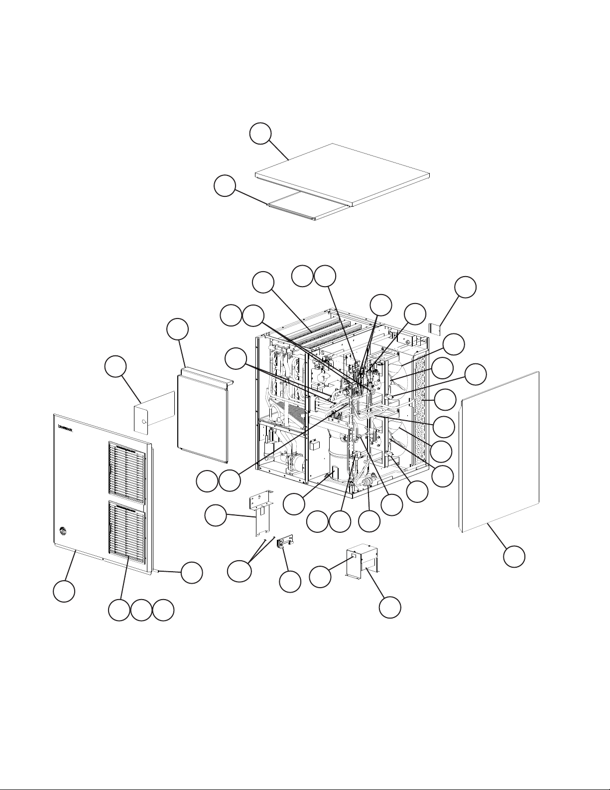
A. Main Assembly & Refrigeration Circuit
KM-1100MAH
E-0 to G-0
3
6
17
18
19
5
27
20
28
12
12a
7
2
1
9 9a 10
21 23
15
11
22 23
14
32
24
26
13
25
30
29
16
33
31
29
8
31
30
4
4
Page 5
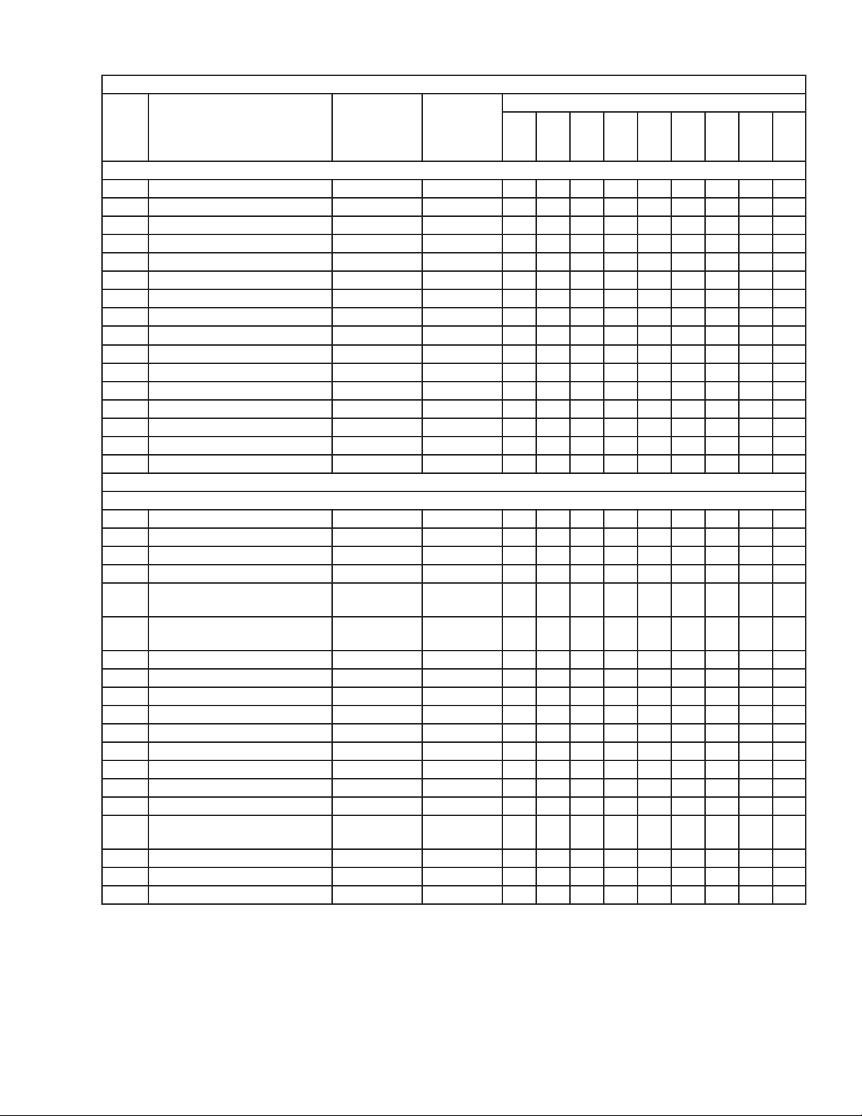
Title: A. Main Assembly & Refrigeration Circuit Model: KM-1100MAH
E-0
Index
No. Description
1 Front Panel 1A3621-01 1
2 Gasket L=762 mm 4A0808L02 1
3 Top Panel 3A1941A01 1
4 Right Side Panel 1A3617G01 1
5 Front Insulation 3A8392G01 1
6 Top Insulation 322714G01 1
7 Control Box Cover 3A2371-01 1
8 Junction Box Cover 433410-01 1
9 Louver 1A0547-01 2
9a Push Retainer 4A2414-01 6
10 Air Filter 2A2062G01 2
11 Bulb Holder 3A3903-01 1
12 Bulb Holder Bracket 322815G02 1
12a Thumbscrew 415949G10 2
13 Main Transformer 4A5695-01 1
14 Voltage Tap Switch 4A1477-01 1
Material or
Model Number Part Number
Main Assembly
to
G-0
Required Number
Refrigeration Circuit
15 Compressor 4A4134-03 1
16 Condenser 1A3559-01 1
17 Evaporator 1A3820G01 1
18 Thermostatic Expansion Valve 4A4008-01 2
19 Thermostatic Expansion Valve
Cover
20 Thermostatic Expansion Valve
Bulb Holder
21 Hot Gas Valve Body 4A3978-01 1
22 Liquid Line Valve Body 4A3276-01 1
23 Valve Coil 4A3277-01 2
24 Check Valve 4A1373-01 2
25 Strainer 441569-02 1
26 High-Pressure Switch 463180-04 1
27 Thermistor 429006-03
28 Thermistor Holder 427430-01 1
29 Fan Motor 4A3158-01 2
30 Fan Motor Capacitor 5MFD,
250VAC
31 Fan Blade 4A3959-01 2
32 Drier 4A2666-01 1
33 Heat Exchanger 1A3601G01 1
3A0944-01 2
3A0107-01 2
443192-02 2
1
5
Page 6

A. Main Assembly & Refrigeration Circuit
KM-1100MWH
E-0 to G-0
3
6
17
21 23
24
8
25
5
7
1
2
20
10
18 19
10a
13
9
12
29
22 23
11
27 28
15 16
30
14
26
4
6
Page 7

Title: A. Main Assembly & Refrigeration Circuit Model: KM-1100MWH
E-0
Index
No. Description
1 Front Panel 1A3621-02 1
2 Gasket L=762 mm 4A0808L02 1
3 Top Panel 3A1941A01 1
4 Right Side Panel 1A3617G01 1
5 Front Insulation 3A8392G01 1
6 Top Insulation 322714G01 1
7 Control Box Cover 3A2371-01 1
8 Junction Box Cover 433410-01 1
9 Bulb Holder 3A3903-01 1
10 Bulb Holder Bracket 322815G02 1
10a Thumbscrew 415949G10 2
11 Main Transformer 4A5695-01 1
12 Voltage Tap Switch 4A1477-01 1
13 Compressor 4A1539-03 1
14 Condenser 3A7323-01 1
15 Water Regulating Valve 4A0911-07 1
16 Male Connector 4A1087-01 1
17 Evaporator 1A3820G01 1
18 Thermostatic Expansion Valve 4A4008-01 2
19 Thermostatic Expansion Valve
Cover
20 Thermostatic Expansion Valve
Bulb Holder
21 Hot Gas Valve Body 4A3978-01 1
22 Liquid Line Valve Body 4A3276-01 1
23 Valve Coil 4A3277-01 2
24 Check Valve 4A1373-01 2
25 Strainer 441569-02 1
26 High-Pressure Switch 463180-05 1
27 Thermistor 429006-03 1
28 Thermistor Holder 427430-01
29 Drier 4A2666-01 1
30 Heat Exchanger 1A3601G01 1
Material or
Model Number Part Number
Main Assembly
Refrigeration Circuit
3A0944-01 2
3A0107-01 2
to
G-0
1
Required Number
7
Page 8

A. Main Assembly & Refrigeration Circuit
KM-1100MRH
E-0 to G-0
3
6
16
1817
19
2220
24
23
8
5
7
2726
10
10a
1
2
9
13
15
12
28
2221
11
30
29
31
14
25
4
8
Page 9

Title: A. Main Assembly & Refrigeration Circuit Model: KM-1100MRH
E-0
Index
No. Description
1 Front Panel 1A3621-02 1
2 Gasket L=762 mm 4A0808L02 1
3 Top Panel 3A1941A01 1
4 Right Side Panel 1A3617G01 1
5 Front Insulation 3A8392G01 1
6 Top Insulation 322714G01 1
7 Control Box Cover 3A2371-01 1
8 Junction Box Cover 433410-01 2
9 Bulb Holder 3A3903-01 1
10 Bulb Holder Bracket 322815G02 1
10a Thumbscrew 415949G10 2
11 Main Transformer 4A5695-01 1
12 Voltage Tap Switch 4A1477-01 1
13 Compressor 4A1539-03 1
14 Receiver 437652-01 1
15 Crankcase Heater 4A5397-02 1
16 Evaporator 1A3820G01 1
17 Thermostatic Expansion Valve 4A4008-01 2
18 Thermostatic Expansion Valve
Cover
19 Thermostatic Expansion Valve
Bulb Holder
20 Hot Gas Valve Body 4A3978-01 1
21 Liquid Line Valve Body 4A3276-01 1
22 Valve Coil 4A3277-01 2
23 Check Valve 4A1373-01 2
24 Strainer 441569-02 1
25 High-Pressure Switch 463180-04 1
26 Thermistor 429006-03 1
27 Thermistor Holder 427430-01 1
28 Drier 4A2666-01
29 Discharge Line Coupling 434136G01 1
30 Liquid Line Coupling 4A3887G01 1
31 Heat Exchanger 1A3601G01 1
Material or
Model Number Part Number
Main Assembly
Refrigeration Circuit
3A0944-01 2
3A0107-01 2
to
G-0
1
Required Number
9
Page 10

B. Water Circuit
KM-1100M_H
E-0 to G-0
46
31
32
45
34
31
32
36
13
38
37
44
39
33
42
30
18
21
43
12
29
14
15
10
48
11
28
27
26
25
16
40
41a
35
17
41
47
20
19
22
1
10
23
24
Pump Motor Assembly
2
8a
9
7
3
4
5
6
8
Page 11

Title: B. Water Circuit Model: KM-1100M_H
Index
No. Description
1 Pump Motor Assembly
(includes items 2 through 8a)
2 Pump Motor 3A7682-01 1
3 Mechanical Seal 4A3820-01 1
4 Pump Flange 215662-01 1
5 Packing 428547-01 1
6 Impeller 428548-01 1
7 Pin 4A0648-01 1
8 Pump Housing 212636-01 1
8a Hexagon Bolt 4×30 7B02-0430 4
9 Pump Motor Bracket 435057-01 1
10 Water Supply Pipe 4A5216G04 1
11 Rubber Gasket 413854-03 1
12 Inlet Water Valve 4A5251-08 1
13 Left Spray Tube 1A0260-02 1
14 Right Spray Tube 1A0260-01 1
15 Spray Guide 2A4282-02 4
16 Float Switch 4A3624-02 1
17 Float Switch Connector 426799-01 1
18 Drain Valve Housing 3A1170-01 1
19 Valve Seat 433705-01 1
20 Spring 322685-01 1
21 O-Ring 7611-G035 1
22 Overow Cap 322816-01 1
23 Overow Pipe 322691-02 1
24 O-Ring 4A1234-01 1
25 Hose (C) 326655-01 1
26 Cleaning Valve Handle 215383-01 1
27 Cleaning Valve Microswitch 4A2546-01 1
28 Cleaning Valve Ball Valve
29 Cleaning Valve Male Adaptor 325826-01 2
30 Distributor A (Tee) 4A0177-01 1
31 Distributor B (Tee) 432426-01 2
32 Silicone Hose L=135 mm 7730I3812 3
33 Right Water Supply Tube 2A0079-02 1
34 Left Water Supply Tube 2A0079-01 1
35 Drain Hose 435092-01 1
36 Vinyl Hose L=470 mm 7716-2025 1
37 Vinyl Hose L=170 mm 7716-2025 1
38 Vinyl Hose L=63 mm 7716-2025 2
39 Vinyl Hose L=47 mm 7716-1519 1
Material or
Model Number Part Number
S-0731 215693A01 1
439293-01 1
Required Number
E-0
to
G-0
11
Page 12

Title: B. Water Circuit Model: KM-1100M_H
Index
No. Description
40 Cube Guide A 214905-01 1
41 Cube Guide B 322644-02 1
41a Thumbscrew 415949G12 1
42 Bypass Hose 439265-01 1
43 Rubber Ring 439236-01 1
44 Spring 435825-01 1
45 Connector 432763-01 1
46 Plug 4A0176-01 4
47 Inlet Hose A 435091-01 1
48 Flange 439267-01 1
Hose Clamp 25 mm 427443-03 11
Material or
Model Number Part Number
Hose Clamps
18 mm 427443-05 3
27 mm 427443-08 2
Required Number
E-0
to
G-0
12
Page 13

C. Control Box Assembly
KM-1100M_H
E-0 to G-0
13
6
3
10
11
X10 X11 X12
KM-1100MRH
4
5
1
2
7a
7
8
12
9
Title: C. Control Box Assembly Model: KM-1100M_H
Index
No. Description
1 Start Capacitor 145-174MFD,
2 Run Capacitor 30MFD,
3 Start Relay 4A1107-13 1
4 Compressor Relay 4A3140-01 1
5 Pump Motor Capacitor 10MFD,
6 Control Transformer 3A0172-01 1
7 Control Board 2A3792-01 1
7a Control Board Support 4A0336-03 4
8 K4 Jumper 4A4883G01 1
9 Control Switch 443119-01 1
10 Fuse Holder 4A5443-01 1
11 Fuse GMD-10A,
12 Bin Control Thermostat 4A2879-02 1
13 Relay (X10 and X11) 406132-07 2
Relay (X12) KM-1100MRH 1
Material or
Model Number Part Number
3A0076-11 1
220VAC
3A2005-03 1
370VAC
443192-01 1
250VAC
4A0893-07 1
250VAC
Required Number
E-0
to
G-0
13
Page 14

D. Accessories & Labels
KM-1100M_H
E-0 to G-0
1
2
Title: D. Accessories & Labels Model: KM-1100M_H
Index
No. Description
1 Hoshizaki Emblem Label 4A0560-01 1
2 Penguin Label 475552L02 1
3 Universal Brace 4A0363-01 2
3a Hex Head Bolt 7B02-0512 2
Material or
Model Number Part Number
Required Number
E-0
to
G-0
14
 Loading...