

Hoshizaki FM-120EE-50 Service Manual

NO. E2EB-679
ISSUED: JUN. 3, 2005
REVISED: JAN. 20, 20 06
HOSHIZAKI
SELF-CONTAINED ICE MAKER
MODEL
CUBELET
FLAKE
CM-110EE
FM-80EE
FM-120EE(-N)
FM-120EE-50(-N)
SERVICE MANUAL

CONTENTS
I. SPECIFICA TIONS ---------------------------------------------------------------------------------------1
1. DI MENSIONS /CONNEC TIONS ------------------------------------------------------------------1
[a] CM-110EE, FM-120EE, FM-120EE-N, FM-80EE --------------------------------------1
[b] FM-120EE-50, FM-120EE-50-N ------------------------------------------------------------2
2. SPECIF ICA TIONS-----------------------------------------------------------------------------------3
[a] CM-110EE ----------------------------------------------------------------------------------------3
[b] FM-120EE ----------------------------------------------------------------------------------------4
[c] FM-120EE-N -------------------------------------------------------------------------------------5
[d] FM-120EE-50 ------------------------------------------------------------------------------------6
[e] FM-120EE-50-N---------------------------------------------------------------------------------7
[f] FM-80EE ------------------------------------------------------------------------------------------8
II. G ENERAL INFO RMA TION----------------------------------------------------------------------------9
1. CO NSTRUCT ION------------------------------------------------------------------------------------9
2. OPERA TION - How i t works---------------------------------------------------------------------12
3. TIMER BOARD-------------------------------------------------------------------------------------13
[a] SOLID- ST A TE CONTROL------------------------------------------------------------------- 13
[b] TIMER BOARD --------------------------------------------------------------------------------13
[c] SEQUENCE ------------------------------------------------------------------------------------14
PAGE
III. INSTALLATION INSTRUCTIONS ----------------------------------------------------------------- 17
1. UNP ACKING----------------------------------------------------------------------------------------17
2. LOCA TI ON ------------------------------------------------------------------------------------------18
3. IN STA LLA TION ------------------------------------------------------------------------------------- 19
4. ELECTRICAL CONNECTION S ---------------------------------------------------------------- 19
5. WA TER SUPPLY AN D DRAIN CONNEC TIONS ------------------------------------------- 20
IV . OP ERA TING I NSTRUC TIONS-------------------------------------------------------------------- 22
1. ST ART UP------------------------------------------------------------------------------------------- 22
2. PREP ARING THE ICEMAKER FOR LONG STORAGE --------------------------------- 23
V . MAIN TENANCE --------------------------------------------------------------------------------------24
1. PERIOD ICAL CLEAN ING -----------------------------------------------------------------------24
2. CLEANI NG OF WA TER SYSTEM -------------------------------------------------------------26
VI. TECHNICAL INFORMA TION---------------------------------------------------------------------- 30
1. WA TER CIRCUI T AND REF RIGERAN T CIR CUIT ----------------------------------------- 30
2. WIRI NG DIA GRAM -------------------------------------------------------------------------------- 31
[a] CM-1 10EE, FM-120EE(-N), FM-120EE-50(-N)----------------------------------------31
[b] FM-80EE ----------------------------------------------------------------------------------------32
3. TI MING C HART ------------------------------------------------------------------------------------33
[a] PRINCIPL E OF OPERATION--------------------------------------------------------------- 33
[b] PROTECTO RS --------------------------------------------------------------------------------33
4. PERFORMANCE DA TA ------------------------------------------------------------------------- 35
[a] CM-110EE --------------------------------------------------------------------------------------35
i

[b] FM-120EE, FM-120EE-50 ------------------------------------------------------------------ 36
[c] FM-120EE-N, FM-120EE-50-N ------------------------------------------------------------37
[d] FM-80EE ----------------------------------------------------------------------------------------38
VII. S ERVICE D IAGNOSI S ---------------------------------------------------------------------------- 39
1. NO IC E PRODU CTION---------------------------------------------------------------------------39
2. LOW ICE PROD UCTION ------------------------------------------------------------------------ 41
3. OTHERS--------------------------------------------------------------------------------------------- 41
VIII. REMOV AL AND REPLACEMENT OF COMPONENTS ----------------------------------43
1. SERVICE FOR REFRIGERAN T LINES------------------------------------------------------43
[a] SER VICE INF ORMA TION------------------------------------------------------------------- 43
[b] REFRIGER ANT RECOVERY -------------------------------------------------------------- 44
[c] EV ACUATION AND REC HARGE ---------------------------------------------------------44
2. BR AZING -------------------------------------------------------------------------------------------- 45
3. COMPRESSOR -----------------------------------------------------------------------------------45
4. DRIER ------------------------------------------------------------------------------------------------47
5. EXP ANSION VALVE------------------------------------------------------------------------------48
6. EV APORATOR ASSEMBL Y -------------------------------------------------------------------- 49
7. F AN MO TOR----------------------------------------------------------------------------------------53
8. FLOAT SWITCH -----------------------------------------------------------------------------------53
9. CONTROL WA TER VAL VE --------------------------------------------------------------------- 54
ii
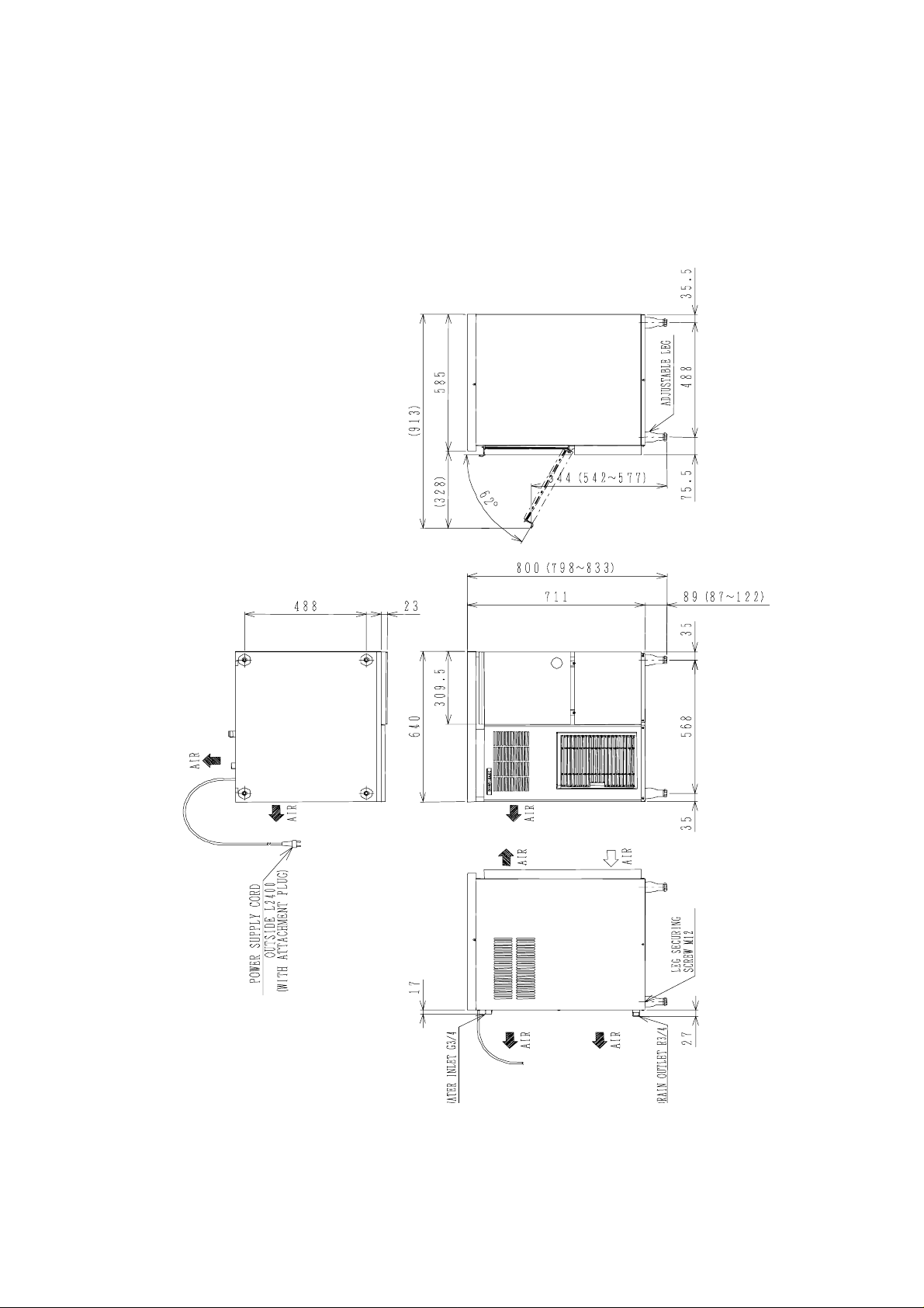
I. SPECIFICATIONS
1. DIMENSI ONS/CONNE CTIONS
[a] CM-110EE, FM-120EE, FM-120EE-N , FM - 8 0EE
1
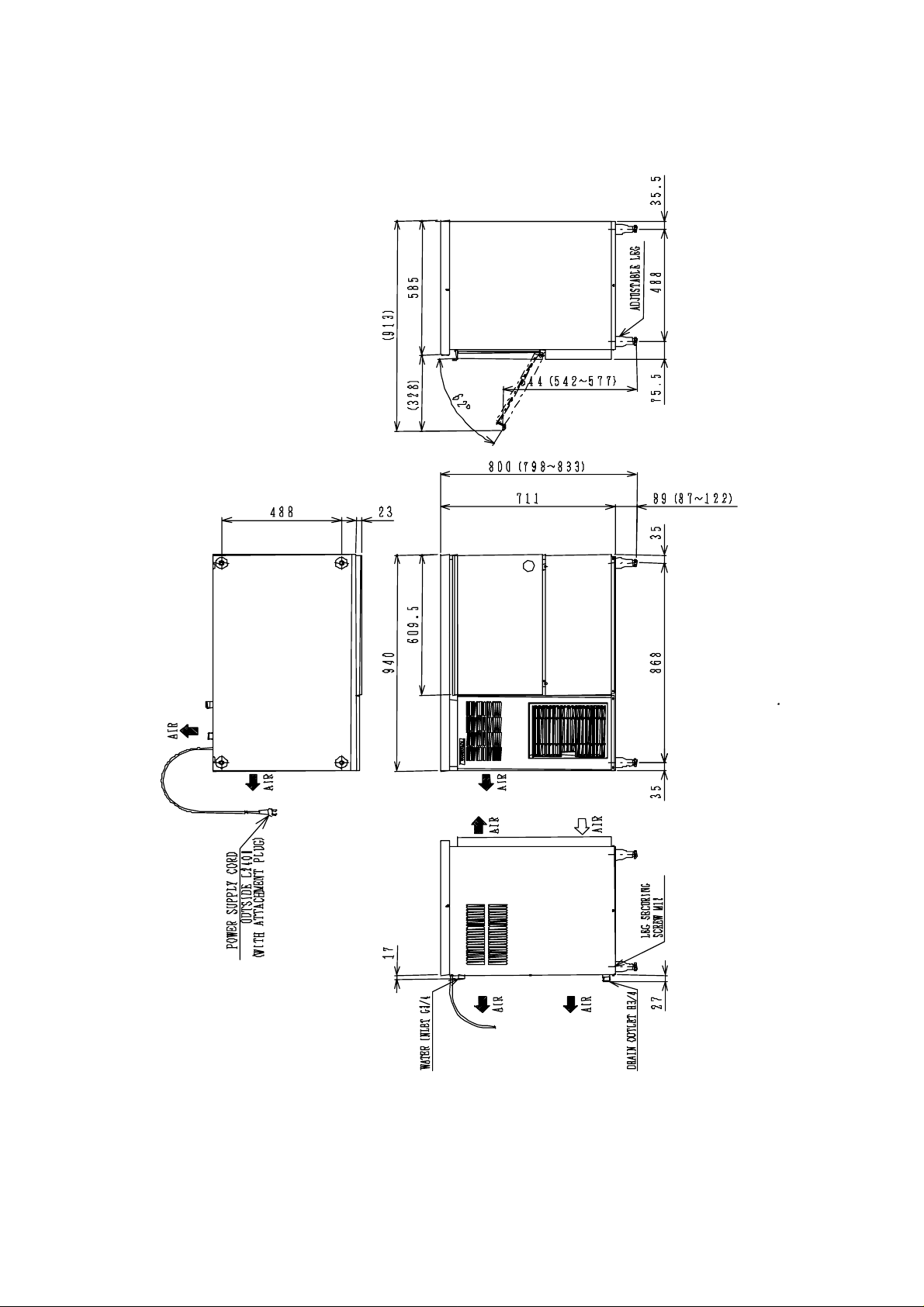
[b] FM-120EE-50, FM-120EE-50-N
2
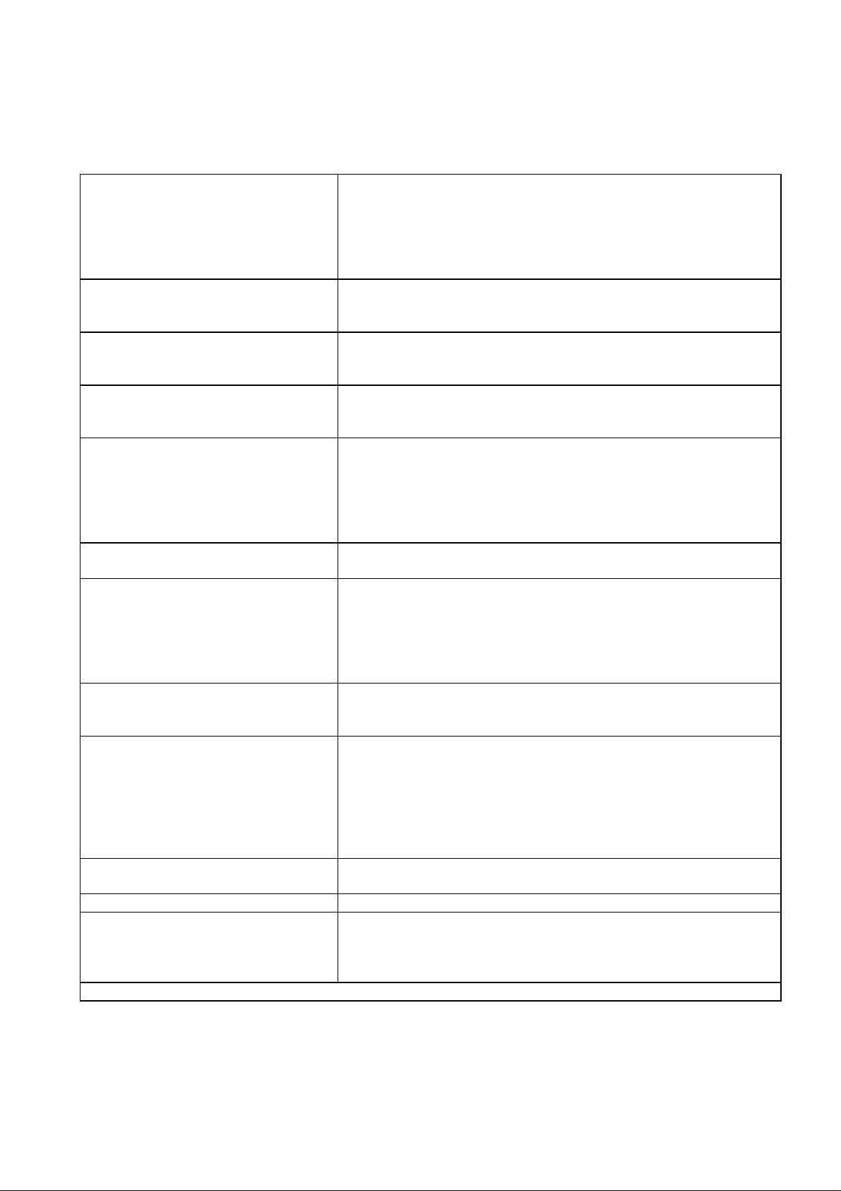
2. SPECIFICATIONS
[a] CM-110EE
AC SUPPLY VOLTAGE
AMPERAGE
STARTING AMPERAGE
ELECTRIC CONSUMPTION
POWER FACTOR
POWER SUPPLY CAPACITY
ICE PRODUCTION PER 24h
WATER CONSUMPTION PER 24h Approx. 0.110 m3 (Ambient temp. 10°C, Water temp. 10°C)
SHAPE OF ICE
MAX STORAGE CAPACITY
DIMENSIONS (DRAWING No.)
EXTERIOR
INSULATION
CONNECTION - ELECTRIC
- WATER SUPPLY
- DRAIN
ICE MAKING SYSTEM
HARVESTING SYSTEM
COMPRESSOR
CONDENSER
HEAT REJECTION
EVAPORATOR
REFRIGERANT CONTROL
REFRIGERANT CHARGE
BIN CONTROL SYSTEM
ICE MAKING WATER CONTROL
ELECTRICAL PROTECTION
COMPRESSOR PROTECTION
GEAR MOTOR PROTECTIO N
LOW WATER PROTECTION
WEIGHT
PACKAGE
ACCESSORIES Scoop, Installation Kit
OPERATION CONDITIONS
AMBIENT TEMP.
WATER SUPPLY TEMP
WATER SUPPLY PRESSURE
We reserve the right to make changes in specifications and design without prior notice.
1 phase 220-240V 50Hz
3.5A (Ambient temp. 32°C, Water temp. 21°C)
13A
525W (Ambient temp. 32°C, Water temp. 21°C)
65%
Min 1.08kVA (4.5A)
Approx. 110 kg (Ambient temp. 10°C, Water temp. 10°C)
Approx. 98 kg (Ambient temp. 21°C, Water temp. 15°C)
Approx. 75 kg (Ambient temp. 32°C, Water temp. 21°C)
Approx. 0.098 m
Approx. 0.075 m
Cubelet
Approx. 32kg - Leveled
(Bin Control Setting Approx. 27kg)
640(W) x 600(D) x 800(H) (mm) (359551)
Stainless Steel, Galvanized Steel (Rear)
Polyurethane Foam
Y-type Con. (with EU Plug)
Inlet G 3/4” (Connected at rear side)
Outlet R 3/4” (Connected at rear side)
Auger type
Direct driven Auger (80W Gear Motor)
Hermetic Compressor 315W Model SC12G
Fin and Tube type forced air cooling
1030W
Copper Tube on Cylinder
Capillary Tube
R134a 150g
Mechanical Bin Control (or Actuator and Reed Switch)
(Time Delay Controlled)
Float Switch and Water Valve
Class I Appliance
6A Circuit Breaker
Auto-reset Overload Protector
Auto-reset Pressure Switch
Manual-reset Circuit Breaker
Auto-reset Thermal Protector
Float Switch and Timer
Net weight 71kg / Gross weight 82 kg
Carton 746mm(W) x 706mm(D) x 922mm(H)
5 - 40°C
5 - 35°C
0.5 - 8 bar (0.05 - 0.8MPa)
3
(Ambient temp. 21°C, Water temp. 15°C)
3
(Ambient temp. 32°C, Water temp. 21°C)
3

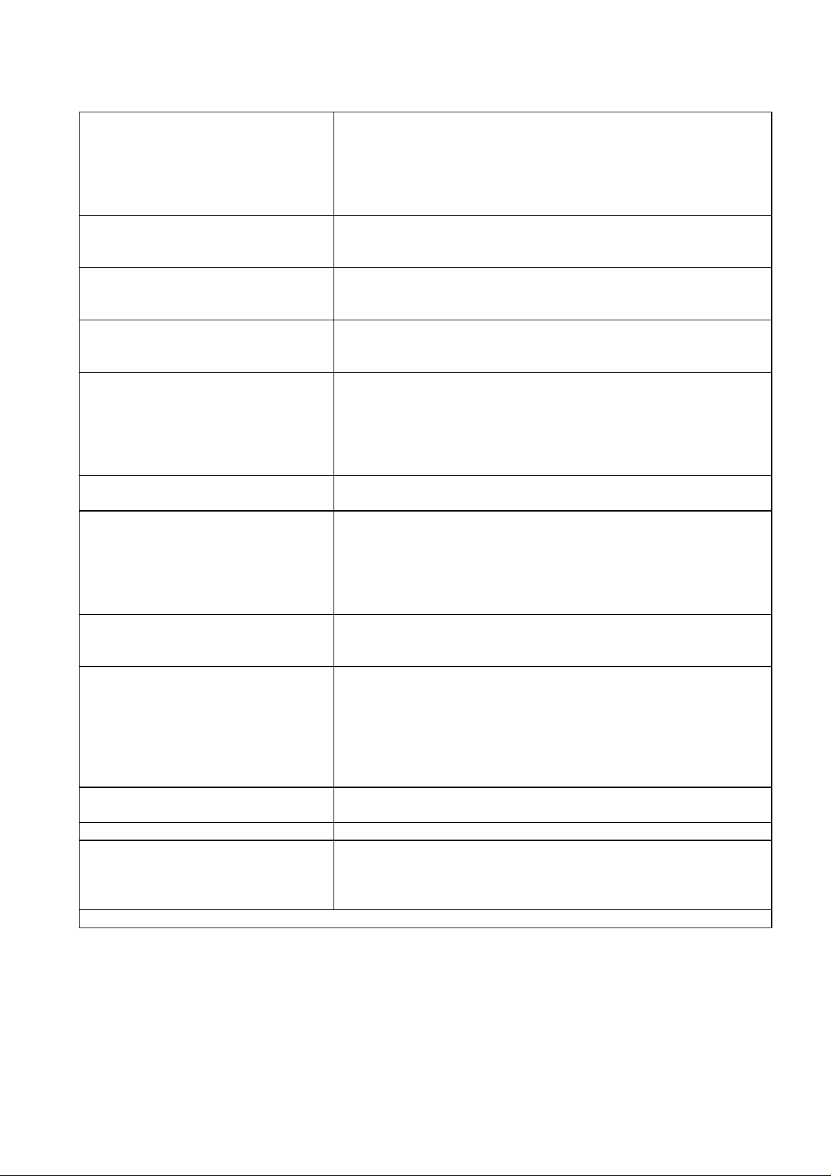
[b] FM-120EE
AC SUPPLY VOLTAGE
AMPERAGE
STARTING AMPERAGE
ELECTRIC CONSUMPTION
POWER FACTOR
POWER SUPPLY CAPACITY
ICE PRODUCTION PER 24h
WATER CONSUMPTION PER 24h Approx. 0.125 m3 (Ambient temp. 10°C, Water temp. 10°C)
SHAPE OF ICE
MAX STORAGE CAPACITY
DIMENSIONS (DRAWING No.)
EXTERIOR
INSULATION
CONNECTION - ELECTRIC
- WATER SUPPLY
- DRAIN
ICE MAKING SYSTEM
HARVESTING SYSTEM
COMPRESSOR
CONDENSER
HEAT REJECTION
EVAPORATOR
REFRIGERANT CONTROL
REFRIGERANT CHARGE
BIN CONTROL SYSTEM
ICE MAKING WATER CONTROL
ELECTRICAL PROTECTION
COMPRESSOR PROTECTION
GEAR MOTOR PROTECTIO N
LOW WATER PROTECTION
WEIGHT
PACKAGE
ACCESSORIES Scoop, Installation Kit
OPERATION CONDITIONS
AMBIENT TEMP.
WATER SUPPLY TEMP
WATER SUPPLY PRESSURE
We reserve the right to make changes in specifications and design without prior notice.
1 phase 220-240V 50Hz
3.5A (Ambient temp. 32°C, Water temp. 21°C)
13A
520W (Ambient temp. 32°C, Water temp. 21°C)
65%
Min 1.08kVA (4.5A)
Approx. 125 kg (Ambient temp. 10°C, Water temp. 10°C)
Approx. 115 kg (Ambient temp. 21°C, Water temp. 15°C)
Approx. 85 kg (Ambient temp. 32°C, Water temp. 21°C)
Approx. 0.115 m
Approx. 0.085 m
3
(Ambient temp. 21°C, Water temp. 15°C)
3
(Ambient temp. 32°C, Water temp. 21°C)
Flake
Approx. 26kg - Leveled
(Bin Control Setting Approx. 21kg)
640(W) x 600(D) x 800(H) (mm) (359549)
Stainless Steel, Galvanized Steel (Rear)
Polyurethane Foam
Y-type Con. (with EU Plug)
Inlet G 3/4” (Connected at rear side)
Outlet R 3/4” (Connected at rear side)
Auger type
Direct driven Auger (80W Gear Motor)
Hermetic Compressor 315W Model SC12G
Fin and Tube type forced air cooling
1030W
Copper Tube on Cylinder
Capillary Tube
R134a 150g
Mechanical Bin Control (or Actuator and Reed Switch)
(Time Delay Controlled)
Float Switch and Water Valve
Class I Appliance
6A Circuit Breaker
Auto-reset Overload Protector
Auto-reset Pressure Switch
Manual-reset Circuit Breaker
Auto-reset Thermal Protector
Float Switch and Timer
Net weight 71kg / Gross weight 82 kg
Carton 746mm(W) x 706mm(D) x 922mm(H)
5 - 40°C
5 - 35°C
0.5 - 8 bar (0.05 - 0.8MPa)
4

[c] FM-120EE-N
AC SUPPLY VOLTAGE
AMPERAGE
STARTING AMPERAGE
ELECTRIC CONSUMPTION
POWER FACTOR
POWER SUPPLY CAPACITY
ICE PRODUCTION PER 24h
WATER CONSUMPTION PER 24h Approx. 0.110 m3 (Ambient temp. 10°C, Water temp. 10°C)
SHAPE OF ICE
MAX STORAGE CAPACITY
DIMENSIONS (DRAWING No.)
EXTERIOR
INSULATION
CONNECTION - ELECTRIC
- WATER SUPPLY
- DRAIN
ICE MAKING SYSTEM
HARVESTING SYSTEM
COMPRESSOR
CONDENSER
HEAT REJECTION
EVAPORATOR
REFRIGERANT CONTROL
REFRIGERANT CHARGE
BIN CONTROL SYSTEM
ICE MAKING WATER CONTROL
ELECTRICAL PROTECTION
COMPRESSOR PROTECTION
GEAR MOTOR PROTECTIO N
LOW WATER PROTECTION
WEIGHT
PACKAGE
ACCESSORIES Scoop, Installation Kit
OPERATION CONDITIONS
AMBIENT TEMP.
WATER SUPPLY TEMP
WATER SUPPLY PRESSURE
We reserve the right to make changes in specifications and design without prior notice.
1 phase 220-240V 50Hz
3.5A (Ambient temp. 32°C, Water temp. 21°C)
13A
525W (Ambient temp. 32°C, Water temp. 21°C)
65%
Min 1.08kVA (4.5A)
Approx. 110 kg (Ambient temp. 10°C, Water temp. 10°C)
Approx. 98 kg (Ambient temp. 21°C, Water temp. 15°C)
Approx. 75 kg (Ambient temp. 32°C, Water temp. 21°C)
Approx. 0.098 m
Approx. 0.075 m
3
(Ambient temp. 21°C, Water temp. 15°C)
3
(Ambient temp. 32°C, Water temp. 21°C)
Nugget
Approx. 32kg - Leveled
(Bin Control Setting Approx. 27kg)
640(W) x 600(D) x 800(H) (mm) (359550)
Stainless Steel, Galvanized Steel (Rear)
Polyurethane Foam
Y-type Con. (with EU Plug)
Inlet G 3/4” (Connected at rear side)
Outlet R 3/4” (Connected at rear side)
Auger type
Direct driven Auger (80W Gear Motor)
Hermetic Compressor 315W Model SC12G
Fin and Tube type forced air cooling
1030W
Copper Tube on Cylinder
Capillary Tube
R134a 150g
Mechanical Bin Control (or Actuator and Reed Switch)
(Time Delay Controlled)
Float Switch and Water Valve
Class I Appliance
6A Circuit Breaker
Auto-reset Overload Protector
Auto-reset Pressure Switch
Manual-reset Circuit Breaker
Auto-reset Thermal Protector
Float Switch and Timer
Net weight 71kg / Gross weight 82 kg
Carton 746mm(W) x 706mm(D) x 922mm(H)
5 - 40°C
5 - 35°C
0.5 - 8 bar (0.05 - 0.8MPa)
5
[d] FM-120EE-50
AC SUPPLY VOLTAGE
AMPERAGE
STARTING AMPERAGE
ELECTRIC CONSUMPTION
POWER FACTOR
POWER SUPPLY CAPACITY
ICE PRODUCTION PER 24h
WATER CONSUMPTION PER 24h Approx. 0.125 m3 (Ambient temp. 10°C, Water temp. 10°C)
SHAPE OF ICE
MAX STORAGE CAPACITY
DIMENSIONS (DRAWING No.)
EXTERIOR
INSULATION
CONNECTION - ELECTRIC
- WATER SUPPLY
- DRAIN
ICE MAKING SYSTEM
HARVESTING SYSTEM
COMPRESSOR
CONDENSER
HEAT REJECTION
EVAPORATOR
REFRIGERANT CONTROL
REFRIGERANT CHARGE
BIN CONTROL SYSTEM
ICE MAKING WATER CONTROL
ELECTRICAL PROTECTION
COMPRESSOR PROTECTION
GEAR MOTOR PROTECTIO N
LOW WATER PROTECTION
WEIGHT
PACKAGE
ACCESSORIES Scoop, Installation Kit
OPERATION CONDITIONS
AMBIENT TEMP.
WATER SUPPLY TEMP
WATER SUPPLY PRESSURE
We reserve the right to make changes in specifications and design without prior notice.
1 phase 220-240V 50Hz
3.5A (Ambient temp. 32°C, Water temp. 21°C)
13A
520W (Ambient temp. 32°C, Water temp. 21°C)
65%
Min 1.08kVA (4.5A)
Approx. 125 kg (Ambient temp. 10°C, Water temp. 10°C)
Approx. 115 kg (Ambient temp. 21°C, Water temp. 15°C)
Approx. 85 kg (Ambient temp. 32°C, Water temp. 21°C)
Approx. 0.115 m
Approx. 0.085 m
3
(Ambient temp. 21°C, Water temp. 15°C)
3
(Ambient temp. 32°C, Water temp. 21°C)
Flake
Approx. 57kg - Leveled
(Bin Control Setting Approx. 41kg)
940(W) x 600(D) x 800(H) (mm) (359552)
Stainless Steel, Galvanized Steel (Rear)
Polyurethane Foam
Y-type Con. (with EU Plug)
Inlet G 3/4” (Connected at rear side)
Outlet R 3/4” (Connected at rear side)
Auger type
Direct driven Auger (80W Gear Motor)
Hermetic Compressor 315W Model SC12G
Fin and Tube type forced air cooling
1030W
Copper Tube on Cylinder
Capillary Tube
R134a 150g
Mechanical Bin Control (or Actuator and Reed Switch)
(Time Delay Controlled)
Float Switch and Water Valve
Class I Appliance
6A Circuit Breaker
Auto-reset Overload Protector
Auto-reset Pressure Switch
Manual-reset Circuit Breaker
Auto-reset Thermal Protector
Float Switch and Timer
Net weight 81kg / Gross weight 94 kg
Carton 1046mm(W) x 706mm(D) x 922mm(H)
5 - 40°C
5 - 35°C
0.5 - 8 bar (0.05 - 0.8MPa)
6

[e] FM-120EE-50-N
AC SUPPLY VOLTAGE
AMPERAGE
STARTING AMPERAGE
ELECTRIC CONSUMPTION
POWER FACTOR
POWER SUPPLY CAPACITY
ICE PRODUCTION PER 24h
WATER CONSUMPTION PER 24h Approx. 0.110 m3 (Ambient temp. 10°C, Water temp. 10°C)
SHAPE OF ICE
MAX STORAGE CAPACITY
DIMENSIONS (DRAWING No.)
EXTERIOR
INSULATION
CONNECTION - ELECTRIC
- WATER SUPPLY
- DRAIN
ICE MAKING SYSTEM
HARVESTING SYSTEM
COMPRESSOR
CONDENSER
HEAT REJECTION
EVAPORATOR
REFRIGERANT CONTROL
REFRIGERANT CHARGE
BIN CONTROL SYSTEM
ICE MAKING WATER CONTROL
ELECTRICAL PROTECTION
COMPRESSOR PROTECTION
GEAR MOTOR PROTECTIO N
LOW WATER PROTECTION
WEIGHT
PACKAGE
ACCESSORIES Scoop, Installation Kit
OPERATION CONDITIONS
AMBIENT TEMP.
WATER SUPPLY TEMP
WATER SUPPLY PRESSURE
We reserve the right to make changes in specifications and design without prior notice.
1 phase 220-240V 50Hz
3.5A (Ambient temp. 32°C, Water temp. 21°C)
13A
525W (Ambient temp. 32°C, Water temp. 21°C)
65%
Min 1.08kVA (4.5A)
Approx. 110 kg (Ambient temp. 10°C, Water temp. 10°C)
Approx. 98 kg (Ambient temp. 21°C, Water temp. 15°C)
Approx. 75 kg (Ambient temp. 32°C, Water temp. 21°C)
Approx. 0.098 m
Approx. 0.075 m
3
(Ambient temp. 21°C, Water temp. 15°C)
3
(Ambient temp. 32°C, Water temp. 21°C)
Nugget
Approx. 65kg - Leveled
(Bin Control Setting Approx. 47kg)
940(W) x 600(D) x 800(H) (mm) (359554)
Stainless Steel, Galvanized Steel (Rear)
Polyurethane Foam
Y-type Con. (with EU Plug)
Inlet G 3/4” (Connected at rear side)
Outlet R 3/4” (Connected at rear side)
Auger type
Direct driven Auger (80W Gear Motor)
Hermetic Compressor 315W Model SC12G
Fin and Tube type forced air cooling
1030W
Copper Tube on Cylinder
Capillary Tube
R134a 150g
Mechanical Bin Control (or Actuator and Reed Switch)
(Time Delay Controlled)
Float Switch and Water Valve
Class I Appliance
6A Circuit Breaker
Auto-reset Overload Protector
Auto-reset Pressure Switch
Manual-reset Circuit Breaker
Auto-reset Thermal Protector
Float Switch and Timer
Net weight 81kg / Gross weight 94 kg
Carton 1046mm(W) x 706mm(D) x 922mm(H)
5 - 40°C
5 - 35°C
0.5 - 8 bar (0.05 - 0.8MPa)
7
[f] FM-80EE
AC SUPPLY VOLTAGE
AMPERAGE
STARTING AMPERAGE
ELECTRIC CONSUMPTION
POWER FACTOR
POWER SUPPLY CAPACITY
ICE PRODUCTION PER 24h
WATER CONSUMPTION PER 24h Approx. 0.850 m3 (Ambient temp. 10°C, Water temp. 10°C)
SHAPE OF ICE
MAX STORAGE CAPACITY
DIMENSIONS (DRAWING No.)
EXTERIOR
INSULATION
CONNECTION - ELECTRIC
- WATER SUPPLY
- DRAIN
ICE MAKING SYSTEM
HARVESTING SYSTEM
COMPRESSOR
CONDENSER
HEAT REJECTION
EVAPORATOR
REFRIGERANT CONTROL
REFRIGERANT CHARGE
BIN CONTROL SYSTEM
ICE MAKING WATER CONTROL
ELECTRICAL PROTECTION
COMPRESSOR PROTECTION
GEAR MOTOR PROTECTIO N
LOW WATER PROTECTION
WEIGHT
PACKAGE
ACCESSORIES Scoop, Installation Kit
OPERATION CONDITIONS
AMBIENT TEMP.
WATER SUPPLY TEMP
WATER SUPPLY PRESSURE
We reserve the right to make changes in specifications and design without prior notice.
1 phase 230V 50Hz
1.78A (Ambient temp. 32°C, Water temp. 21°C)
5.41A
0.3kW (Ambient temp. 32°C, Water temp. 21°C)
67%
Min 0.52kVA (2.0A)
Approx. 85 kg (Ambient temp. 10°C, Water temp. 10°C)
Approx. 75 kg (Ambient temp. 21°C, Water temp. 15°C)
Approx. 60 kg (Ambient temp. 32°C, Water temp. 21°C)
Approx. 0.750 m
Approx. 0.600 m
3
(Ambient temp. 21°C, Water temp. 15°C)
3
(Ambient temp. 32°C, Water temp. 21°C)
Flake
26kg - Leveled
640(W) x 600(D) x 800(H) (mm)
Stainless Steel, Galvanized Steel (Rear)
Polyurethane Foam
Y-type Con. (with EU Plug)
Inlet G 3/4” (Connected at rear side)
Outlet R 3/4” (Connected at rear side)
Auger type
Direct driven Auger (40W Gear Motor)
Hermetic Compressor Model TLS6F
Fin and Tube type forced air cooling
470W (Ambient temp. 32°C, Water temp. 21°C)
Copper Tube on Cylinder
Capillary Tube
R134a 140g
Mechanical Bin Control (or Actuator and Reed Switch)
(Time Delay Controlled)
Float Switch and Water Valve
5A Circuit Breaker, Earthing Wire
6A Circuit Breaker
Auto-reset Overload Protector
Auto-reset Pressure Switch
Manual-reset Circuit Breaker
Auto-reset Thermal Protector
Float Switch and Timer
Net weight 65kg / Gross weight 75 kg
Carton 746mm(W) x 706mm(D) x 922mm(H)
5 - 40°C
5 - 35°C
0.5 - 8 bar (0.05 - 0.8MPa)
8

II. GENERAL INFORMATION
1. CONSTRUCTION
Self-containe d cub el et icemaker model C M - 110EE and self-contai ned flaker models FM120EE, FM-120EE- N, FM- 120EE-50 , FM-120E E-50- N and FM-80 EE include Wat er Supply , Ev aporator , Condensing and Control Assemblies.
Top Panel
Door
Front Panel (Left)
Power Supply Cord
Air Filter
Spout
Evaporator
Reservoir
Compressor
Front Cover
Louver
Bin Control Switch
Drainboard
Circuit Breaker
Control Box
Gear Motor
Fan Motor
Condenser
9
ICE MAK IN G U N IT [CM-110EE, FM-120EE-N, FM-120EE-50-N]
10
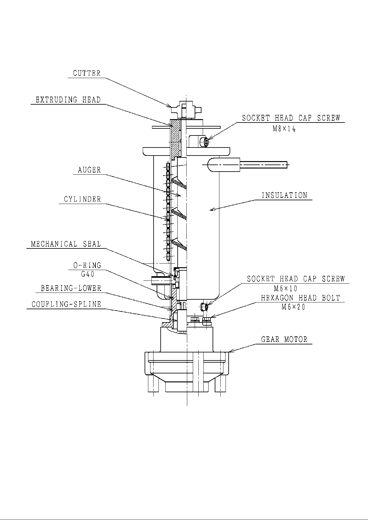
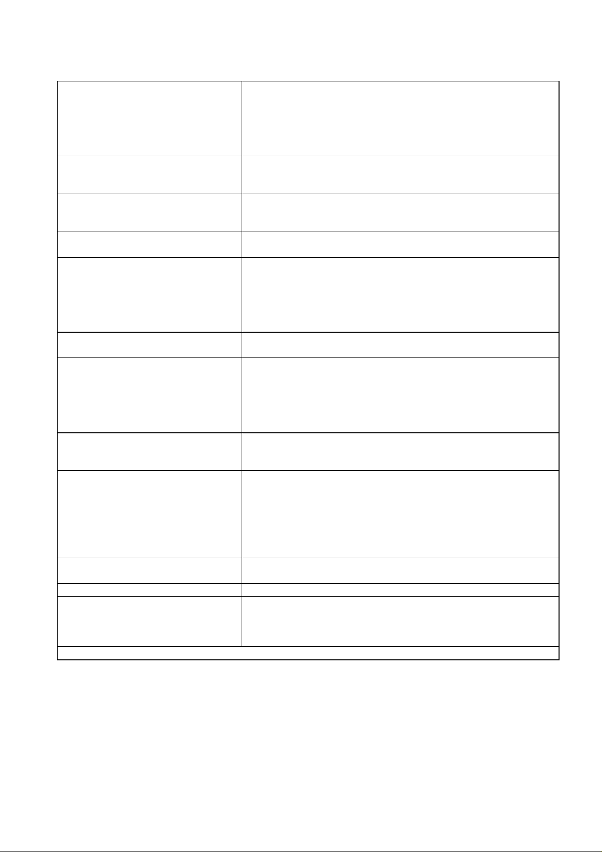
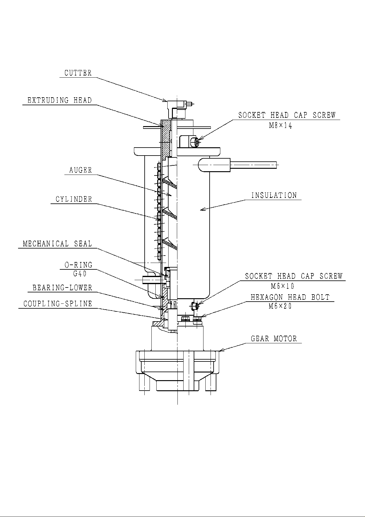
ICE MAK I NG UNIT [FM-120EE, FM-120EE-50, FM-80EE]
11

2. OPERATION - How it works
Potable water flows from the ex ternal supply tap and enters the water inlet on the machine,
passes through an electr ically operated Water Valve before flowing i nto the Reservoir Tank.
From the Tank, water flows by gravity into the bottom of the Evaporato r to completely surround
the Auger and fil l the Evapor ator wit h water to the same level as in the Reservoi r Tank.
Water leak age at the bo ttom of the Evapo rator is pr evente d by the us e of a mechanical seal.
The Evaporator serves to change the water i nto ice by using a heat exchange process in
conjunction wi th the Compr essor/Condenser assembly.
As water is used and turned into ice, the level in the Ev aporator and the Reservoir Tank will
fall. At a pre-determined level , a dual action Float Switch fitt ed to the Reservoir T ank electrically
commands the Water Valve to open and refill the Tank. This system functions therefore to
maintain a constant w ater level i nside the Evaporator ass embly.
The Auger, which is located inside the Evaporator is driven by an external Gear Motor
assembly . The rotating Auger carries the ice upwards wh ere it is pressed ag ainst the Extruding
Head at the top o f the Evapor ator to remove excess w ater, before finally being e xtrude d and
broken into irregular shapes and siz es of ice by the Flake/Nugg et Cutter or into cubelet ic e.
The continuous flow of ice is then pushed into the Ice S pout and falls by gravity into the S torage
Bin below .
Moving the Operation Switch, located on t he Control Box, to the “ON” po sition starts an
automatic and continuous icemaki ng process. When the S torage Bin has fill ed with ice, the
Bin Control Switch, located at the top of the Storage Bin, stops the icemaking process. When
ice is removed from the Storage Bin, the Bin Control Switch will automatically reset and
restar t the i cema king pro cess .
12

3. TIME R BOARD
[a] SOLID-STATE CONTROL
1) An exclusive H OSHIZAKI solid-state control is employed in C M-110EE, FM-120EE, FM120EE-N, FM-120EE-50, FM-120EE-50-N and FM-80EE self-contained icemakers.
2) A Pr inted Circ uit Board (her eafter cal led “T imer Board” ) incl udes a stable and high- quality
control sy stem.
3) No adjustment is requir ed.
[b] TIMER BOARD
CAUTION
1. Fragi le, hand le ver y care fully .
2. A ti mer board contains CMOS (Complementary Metal-Oxide Semiconductor)
integrated circuits, which are susceptible to failure due to static discharge. It
is especially important to either wear an anti-static wrist strap or touch a
metal part of the machine before servicin g to be static free.
3. Do not touch the electronic devices on either side of the board to prevent
damage.
4. Do not change wiring and connections. Especially, never misconnect
terminals.
5. Do not repair the electronic devices or parts on the board in the field. Always
replace the whole board assembly w hen it fails.
The icemaker is controlled by the T imer Board for the follow ing purposes:
1) To prevent the Gear Motor and the Compr essor from st arting or s topping simul taneously.
2) To reduce ice remaining in the Evaporator.
3) To protect the unit in case of low w ater and l ow water pr essure.
4) To protect the unit from short cyclin g if the Bin Contro l resets q uickly.
13

[c] SEQUENCE
Fig. 1
Fig. 2
14

CONTROL (CTL)
PROTECT (PRT)
X1 RELAY
(GEAR MOTOR)
X2 RELAY
(COMPRESSOR)
PART CODE 437305-02
MODEL H2AA144C02
RATI NG 24 V AC 50/60Hz
T
1
T
2
T
3
T
4
T
5
T
6
60±15 sec.
90±22 sec.
150±45 sec.
Max. 1 sec.
Max. 0.25 sec.
Max. 1 sec.
Fig. 3
Note: “T” (ti me) functions of the T imer Boar d are non-adjust able.
15
 Loading...