

Page 1
Hoshizaki
Hoshizaki America, Inc.
Modular Flaker
Models
F-450MAH(-C)
“A Superior Degree
of Reliability”
www.hoshizaki.com
PARTS LIST
Number: 71194
Issued: 10-09-2001
Revised: 4-1-2011
Page 2

CONTENTS
Auxiliary Codes ...................................................................................................................... 3
Note About Ordering Parts .................................................................................................... 3
Material Abbreviations ........................................................................................................... 4
A. Ice Flaker Assembly .......................................................................................................... 5
B. Ice Making Unit ................................................................................................................. 8
C. Refrigeration Circuit ......................................................................................................... 10
D. Water Circuit .................................................................................................................... 12
E. Control Box Assembly...................................................................................................... 14
F. Chute Assembly ............................................................................................................... 16
G. Label Location ................................................................................................................. 18
H. Accessories & Packaging ................................................................................................ 20
2
Page 3

Auxiliary Codes
F-450MAH
L-0 April 2001
M-0 December 2001
N-0 December 2002
P-0 December 2003
P-1 June 2004
Q-0 December 2004
R-0 December 2005
S-0 January 2007
S-1 November 2007
T-0 January 2008
U-0 January 2009
V-0 January 2010
V-1 April 2010
V-2 May 2010
V-3 September 2010
A-0 January 2011
A-1 June 2011
F-450MAH-C
L-0 April 2001
M-0 February 2002
N-1 December 2002
P-0 December 2003
P-1 July 2004
Q-0 December 2004
R-0 December 2005
S-0 January 2007
S-1 November 2007
T-0 February 2008
U-0 January 2009
V-0 January 2010
V-1 April 2010
V-2 May 2010
V-3 December 2010
A-0 January 2011
A-1 June 2011
Auxiliary Code Breakdown
The auxiliary code is the rst two characters in the serial number. The rst character
indicates the year. Years progress or regress in alphabetical order. The series runs from
"A" through "V" and the letters "I" and "O" are skipped. The second character indicates
signicant part changes within a year. Base is "0" and this number advances for each
change. In cases where there is a letter in parentheses, this designates the month. This
is the last character in the serial number. The series runs from "(A)" through "(M)" and the
letter "(I)" is skipped. This designation is only included when identifying a parts change
within an auxiliary code.
Note About Ordering Parts
Most assemblies cannot be ordered as complete units; parts in the assemblies generally
must be ordered separately.
3
Page 4

Material Abbreviations
ALUMINUM
AL = Aluminum
COPPER
CU = Copper
PLASTIC
ABS = Acrylonitrile -butadiene -styrene
AC = Polyacetal
EVA = Ethylene vinyl acetate
PA = Polyamide = Nylon
PC = Polycarbonate
PE = Polyethylene
PES = Polyester
PETP = Polyethylene terephthalate = Tetlon
PP = Polypropylene
PS = Polystyrene
PTFE = Polytetrauoroethylene = Teon
PUR = Polyurethane
PVC = Polyvinyl chloride
RUBBER
VN = Vinyl Nitrile
EPDM = EP rubber
NBR = Nitrile butadiene rubber
NR = Natural rubber
NP = Neoprene
SI.R = Silicone rubber
SY.R = Synthetic rubber
EPH = Epichlorohydrin
STEEL
GS = Galvanized steel
SS = Stainless steel
PS = Plated steel
PAS = Primed steel
4
Page 5
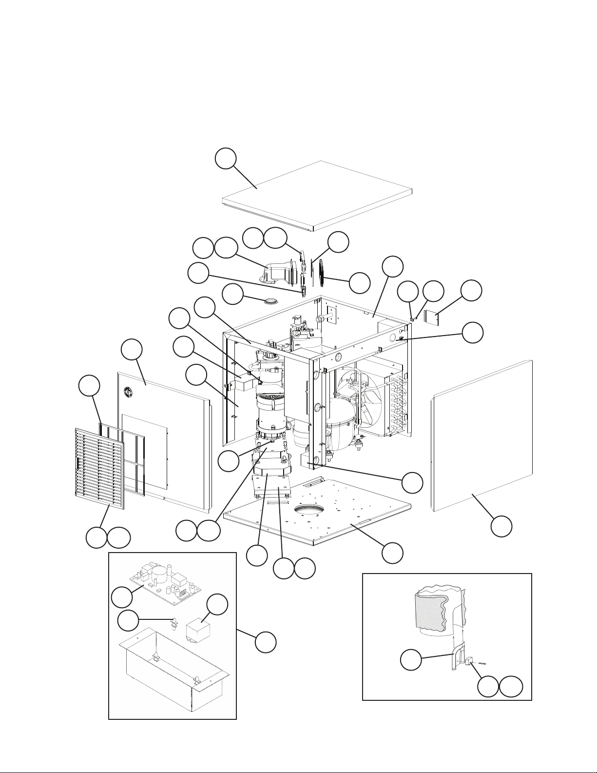
A. Ice Flaker Assembly
F-450MAH(-C)
L-0 to A-1
17
23
17a
19
19a
20
26
25
25a
24
11
7
10
18
22
6
10a
15
1
3
16
14
13
4
5
12
21
9
8a
8
2
30
31
F-450MAH-C
L-0, M-0
32
29
27
F-450MAH-C
L-0, M-0
28
28a
5
Page 6
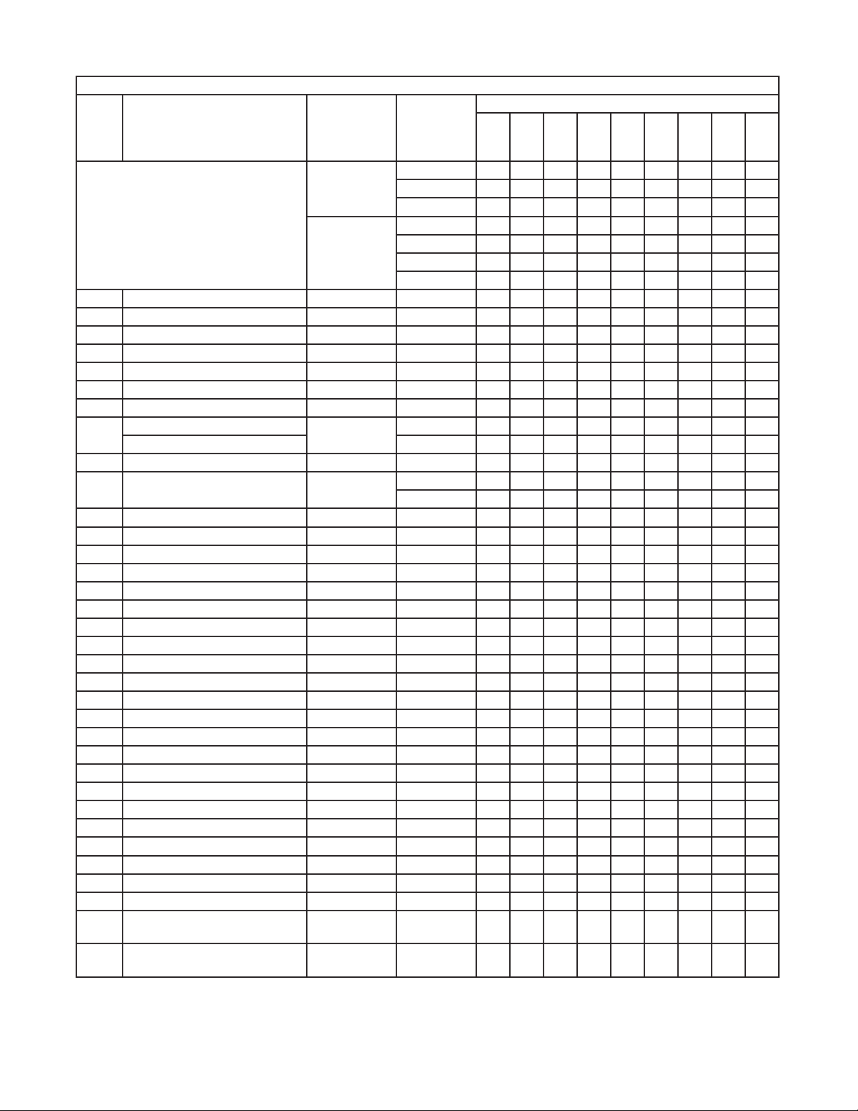
Title: A. Ice Flaker Assembly Model: F-450MAH(-C)
L-0
N-1
S-1
Index
No. Description
Ice Flaker Assembly
Order Assembly Parts Individually
1 Hex Bolt 7B02-0812 3 3 3 3
2 Chassis 2A1178G01 1 1 1 1
3 Rear Panel 2A0916G01 1 1 1 1
4 Junction Box Cover 433410-01 1 1 1 1
5 Side Frame (R) 2A0917G01 1 1 1 1
6 Front Frame 2A0918G01 1 1 1 1
7 Reservoir Bracket 2A0919G01 1 1 1 1
8 Gear Motor Bracket 3A0396G01 1 1 -
Drain Pan Bracket 4A4314G01 1 1
8a Hex Bolt 8×12, SS 7B02-0812 2 2 2 2
9 Drain Pan 323765G02 1 1 -
10 Gear Motor Bracket 4A4308-01 1 1
10a Socket Head Cap Screw 8×20, SS 7S12-0820 4 4
11 Evaporator Strap 4A1262-01 1 1 1 1
12 Barrier 4A0688-01 1 1 1 1
13 Ground Screw 433304-02 1 1 1 1
14 Square Washer 433537-02 1 1 1 1
15 Evaporator Packing 427151-01 1 1 1 1
16 Spout Packing 321037-01 1 1 1 1
17 Spout 2A0915-01 1 1 1 1
17a Thumbscrew 415949G08 3 3 3 3
18 Lower Spout Strap 321038G02 1 1 1 1
19 Upper Spout Strap 328703-02 1 1 1 1
19a Wing Nut 7E12-0600 2 2 2 2
20 Chute Bracket 4A1712-01 1 1 1 1
21 Side Panel (R) 2A2067G01 1 1 1 1
22 Side Panel (L) 2A2066G01 1 1 1 1
23 Top Panel 2A2064-01 1 1 1 1
24 Front Panel 2A2065-01 1 1 1 1
25 Louver 1A0547-01 1 1 1 1
25a Push Retainer 4A2414-01 3 3 3 3
26 Air Filter 2A2062G01 1 1 1 1
27 Sensor Housing F-450MAH-C 2A0996-01 1 28 Photoelectric Sensor
(Bin Control)
28a Cross Recessed Pan Head
Tapping Screw
Material or
Model Number Part Number
F-450MAH 1A0549A01 1 1 -
1A0549A04 1 1A1996A01 1
F-450MAH-C 1A0549A02 1 -
1A0549A03 1 1A0549A05 1 1A1996A02 1
4A4354G01 1 1
F-450MAH-C 4A1173-01 1 -
F-450MAH-C 7C11I1434 2 -
to
N-0
to
S-0
V-0
to
Required Number
V-1
to
A-1
6
Page 7

Title: A. Ice Flaker Assembly Model: F-450MAH(-C)
L-0
Index
No. Description
29 Power Supply Assembly
(includes items 29 through 31)
30 Photoelectric Sensor
(Bin Control) Power Supply
31 Board Support F-450MAH-C 4A0336-03 4 32 Photoelectric Sensor
(Bin Control) Relay
Material or
Model Number Part Number
F-450MAH-C 4A1315A01 1 -
F-450MAH-C 4A1355-01 1 -
F-450MAH-C 4A1382-01 1 -
to
N-0
N-1
to
S-0
Required Number
S-1
V-1
to
to
V-0
A-1
7
Page 8

B. Icemaking Unit
F-450MAH(-C)
L-0 to A-1
12
11
F-450MAH
9
12
11
F-450MAH-C
11a 11b
10
3
8
10a 10b
7
6
3a
2
5
2b
2a
4
1
8
Page 9

Title: B. Icemaking Unit Model: F-450MAH(-C)
L-0
Q-0
S-1
Index
No. Description
Icemaking Unit
Order Assembly Parts Individually
(for mounting hardware, see section
"A" item 1)
1 Gear Motor 4A2193-01 1 1 -
2 Gear Motor Barrier 3A1037-01 1 1 -
Gear Motor Cover 3A4584-01 1 1
2a FT Screw 4×8, SS 7F32-0408 2 2 -
Truss Head Screw 5×8, SS 7C32-0508 2 2
2b Rubber Washer 4A5268-02 2 2
3 Evaporator Assembly
(includes items 4 through 12)
Order Assembly Parts
Individually
3a Bolt 6×20 4A1989-01 4 4 4 4
4 Spline Coupling 418316-01 1 1 1 1
5 Housing 206013G03 1 1 1 1
6 "O" Ring 7616-G040 1 1 1 -
7 Mechanical Seal 432491-01 1 1 1 1
8 Ring 432494-01 1 1 1 1
9 Auger 341448G01 1 1 1 1
10 Evaporator 2A1699G01 1 -
10a Socket Head Cap Screw 6×10, SS 7S12-0610 4 4 4 4
10b Split Lock Washer 6, SS 7L22-0600 4 4 4 4
11 Extruding Head F-450MAH 340077G01 1 1 1 1
11a Seal Bolt M8 P01768-01 3 3 3 3
11b Washer 453791-01 3 3 3 3
12 Cutter F-450MAH 453790-01 1 1 1 1
Material or
Model Number Part Number
F-450MAH 3A0841A01 1 1 -
3A0841A03 1 1
F-450MAH-C 3A0841A02 1 1 -
3A0841A04 1 1
4A4321-01 1 1
F-450MAH
HS-2001
F-450MAH-C
HS-2002
F-450MAH-C 327141G01 1 1 1 1
F-450MAH-C 440905-01 1 1 1 1
339866A01 1 339866A03 1 1 1
339866A02 1 339866A04 1 1 1
4A4755-01 1
2A3310G01 1 1 1
to
P-1
to
S-0
to
U-0
Required Number
V-0
to
A-1
9
Page 10

C. Refrigeration Circuit
F-450MAH(-C)
L-0 to A-1
10
7
14
9a
9
8a
8
14
15 16
L-0 to V-0
12
6
13
11
1a
1
1b
1c
2
4
3
5
10
Page 11

Title: C. Refrigeration Circuit Model: F-450MAH(-C)
Required Number
L-0
P-1
S-1
V-1
Index
No. Description
Refrigeration Circuit
Order Assembly Parts Individually
1 Compressor
1a Grommet 434403-01 4 4 4 -
1b Spacer 434404-01 4 4 4 -
1c Bolt 8×45 437889-01 4 4 4 4 4
2 Protector 4A1805-01 1 1 1 -
3 Protector Holder 437339-01 1 1 1 4 Terminal Cover 4A4479F01 1 1
5 Spring Clip 4A4479F02 1 1
6 Condenser 2A0923-01 1 1 1 1 1
7 Shroud 2A0908-01 1 1 1 1 1
8 Fan Motor Bracket 3A0828-01 1 1 1 1 1
8a Hex Head Bolt w/Washer 5×12, SS 7B0230512 4 4 4 4 4
9 Fan Motor 440911-01 1 -
9a Self-Locking Nut 7N21I0832 4 4 4 4 4
10 Fan Blade 444898-01 1 1 1 1 1
11 Drier 4A1113-01 1 1 1 1 1
12 Expansion Valve 4A4493-01 1 1 1 1 1
13 Expansion Valve Cover 4A1168-01 1 1 1 1 1
14 High-Pressure Switch 433441-05 1 1 1 -
15 Expansion Valve Bulb Holder 3A0112-01 1 1 1 -
16 Clamp 443461-01 1 1 1 1 1
Material or
Model Number Part Number
2A0926A01 1 1 1 2A5930A01 1 2A5930A02 1
RS43C2E-CAA-219
RST45C1ECAA-202
4A2300-01 1 1 1 4A4479-01 1 1
4A2593-01 4 4
4A2595-01 4 4
4A4481-01 1 1
4A3158-01 1 1 1 1
463180-05 1 1
3A0107-01 1 1
to
P-0
to
S-0
to
V-0
to
V-3
A-0
A-1
11
Page 12

D. Water Circuit
F-450MAH(-C)
L-0 to A-1
1
4
8
9
3
11
5
10
12
7
13
6
18
14
2
15
16
19
17
12
20
Page 13

Title: D. Water Circuit Model: F-450MAH(-C)
Index
No. Description
Water Circuit
Order Assembly Parts Individually
1 Water Valve Bracket 3A0553-01 1 1
2 Water Supply Pipe 4A0891G01 1 1
3 Washer 4A0867-01 1 1
4 Inlet Water Valve 4A0865-01 1 1
5 Drain Valve Bracket 4A1264-01 1 1
6 Drain Valve 4A2077-01 1 -
7 Reservoir 2A0753-01 1 1
8 Float Switch 435490-01 1 1
9 Reservoir Cover 214810-01 1 1
10 Reservoir Inlet 4A0869-01 1 1
11 Drain Fitting 4A0776G01 1 1
12 Reservoir Separator 4A1255-01 1 1
13 Reservoir Hose 4A1165-05 1 1
14 Silicone Hose L=230 7730I3896 1 1
15 Vinyl Hose L=65 7716-0913 1 1
16 Vinyl Hose L=270 7716-2025 1 1
17 Vinyl Hose L=80 7716-2025 1 1
18 Vinyl Hose L=355 7725-1923 1 1
19 Te e 4A1331-01 1 1
20 Silicone Hose L=340 7730-1822 1 1
Hose Clamp 4A2017-01 5 5
Hose Clamp 4A2017-02 1 1
Hose Clamp 4A2017-08 5 5
Hose Clamp 4A2017-05 1 1
Hose Clamp 4A2017-06 1 1
Material or
Model Number Part Number
2A0942A01 1 1
4A2772-01 1
Clamps
L-0
M-0
Required Number
N-0
to
A-1
13
Page 14

E. Control Box Assembly
F-450MAH(-C)
L-0 to A-1
18
4
5
8
2
6
3
19
11
12
13
1
9
10
14
14
7
20
16
15
21
17
Page 15

Title: E. Control Box Assembly Model: F-450MAH(-C)
Required Number
M-0
S-1
V-1
Index
No. Description
Control Box Assembly
Order Assembly Parts Individually
1 Control Box Cover 3A0411-01 1 1 1 1 1
2 Water Control Relay 24VAC 406132-03 1 1 1 1 1
3 Gear Motor Relay 24VAC 406133-04 1 1 1 1 1
4 Circuit Protect Relay 240VAC 418271-05 1 1 1 1 1
5 Gear Motor Protect Relay 120VAC 418271-03 1 1 1 1 1
6 Transformer 4A0557-01 1 1 1 1 1
7 Start Relay(Starter) 4A1107-11 1 1 1 1 1
8 Start Capacitor 243-292MFD,
9 Run Capacitor 15MFD,
10 Strap 434580-10 1 -
11 Gear Motor Capacitor 12MFD,
12 Rocker Switch 4A0558-01 1 1 1 1 1
13 Toggle Switch 4A2332-01 1 1 1 1 1
14 Fuse Holder 4A0892-01 1 1 1 1 -
15 Fuse AGC-1, 1A,
16 Control (Timer) Board 437305-01 1 1 1 1 1
17 Board Support 4A0336-03 4 4 4 4 4
18 Drain Timer 4A0889-01 1 1 1 1 1
19 Fan Motor Capacitor 5MFD,
20 Fuse Holder 4A0892-02 1 1 1 1 -
21 Fuse 1.5A 4A0893-04 1 1 -
Material or
Model Number Part Number
2A0953A01 1 1 2A0953A02 1 2A0953A03 1 1
3A0076-10 1 1 1 -
115VAC
243-292MFD,
165VAC
370VAC
15MFD,
370VAC
35MFD,
440VAC
330VAC
20MFD,
350VAC
250V
250VAC
2.0A 4A0893-05 1 1 1
3A0076-20 1 1
439943-04 1 -
3A2005-08 1 1 -
3A2005-12 1 1
4A2262-02 1 1 1 1
4A0894-01 1 1 -
4A4319-01 1 1 1
4A3449-01 1
4A0893-01 1 1 1 1 1
443192-02 1 1 1 1 1
4A3449-02 1
L-0
to
S-0
to
V-0
to
V-3
A-0
A-1
15
Page 16

F. Chute Assembly
F-450MAH(-C)
L-0 to A-1
11
11a
11b
10
10a
6
12
5a
9
1
8
4a
4
7
5
3
F-450MAH-C L-0, M-0
For Photoelectric Sensor, see
"A. Ice Flaker Assembly".
1
2
2
3
16
Page 17

Title: F. Chute Assembly Model: F-450MAH (All), F-450MAH-C (N-1 and Later)
L-0
T-0
to
(F)
Index
No. Description
Chute Assembly
Order Assembly Parts Individually
1 Chute 2A1308-01 1 1
2 Chute Insulation 2A0989-01 1 1
3 Tie 436531G01 3 3
4 Chute Baffle (A) 3A0400G01 1 1
4a Wing Nut 7E12-0400 3 3
5 Chute Baffle (B) 3A0399G01 1 1
5a Wing Nut 7E12-0400 3 3
6 Bin Control 3A1744G01 1 1
7 Actuator 436848G01 1 1
8 Shaft 436851-01 1 1
9 Snap Pin 715S-0005 2 2
10 Plate SS 4A2039-01 1 -
10a Thumbscrew 415949G10 2 2
11 Proximity Switch 4A2033-01 1 1
11a Thumbscrew 415949G08 2 2
11b Truss Head Screw (Ground) 7C32-0408 1 1
12 Packing 441217-01 1 -
Material or
Model Number Part Number
HS-2007 2A1705A03 1 1
ABS 1
T-0
(E)
A-1
to
Required Number
Title: F. Chute Assembly Model: F-450MAH-C (L-0, M-0)
Index
No. Description
Chute Assembly
Order Assembly Parts Individually
1 Chute 2A0925-01 1
2 Chute Insulation 2A0989-01 1
3 Tie 436531G01 3
Material or
Model Number Part Number
F-450MAH-C 3A0874A01 1
L-0
M-0
Required Number
See Chute Assembly Above
for N-1 and Later
17
Page 18

G. Label Location
F-450MAH(-C)
L-0 to A-1
1
6
16
12
13
10
S-1 and Later
9
L-0 to S-0
11
15
14
8
4
2
3
7
Title: G. Label Location Model: F-450MAH(-C)
Index
No. Description
Label Location
Order Assembly Parts
Individually
Material or
Model Number Part Number
F-450MAH 2A2080A01 1 -
F-450MAH-C 2A2080A02 1 -
5
Required Number
L-0
N-0
to
(J)
N-0
to
(H)
P-0 P-1
2A2080A05 1 1 1 2A2080A09 1 2A2080A11 1 1
2A2080A06 1 1 1 2A2080A10 1 2A2080A12 1 1
Q-0
to
S-0
S-1
to
V-0
V-1
to
A-0 A-1
18
Page 19

Title: G. Label Location Model: F-450MAH(-C)
Required Number
L-0
N-0
to
(J)
Index
No. Description
1 Instruction Sheet 2A1054-01 1 1 1 1 2 Emblem 4A0560-01 1 1 1 1 1 1 1
3 Model Number Label F-450MAH 4A2233-10 1 -
4 Penguin-Ha-L Label 456246-01 1 1 1 1 1 1 1
5 Air Filter Label 426177-01 1 1 1 1 1 1 1
6 Instruction Label 326371-01 1 1 1 1 1 1 7 Maintenance Label 2A3445-01 1 1 1 1 1 1 -
8 Nameplate F-450MAH 3A1833-01 1 -
9 Tag-Warning: Electrical
Connection
10 Control Label 4A1613-01 1 1 1 1 -
11 Caution Label (E) 439145-01 1 1 1 1 1 1 -
Warning Label (E) 4A4923-01 1
12 Wiring Label F-450MAH 2A1830-01 1 1 1 1 -
13 Caution Label (H) 439148-01 1 1 1 1 1 1 -
Warning Label (H) 4A4795-01 1
14 Rating Label F-450MAH 3A1834-01 1 1 -
15 Fuse Label (GM) 4A4278-01 1 1 1 1 1 1 1
16 R404A Label 4A0960-01 1 1 1 1 1 -
Material or
Model Number Part Number
F-450MAH-C 4A2233-11 1 -
2A6531-01 1
3A2542-01 1 1 1 3A4620-01 1 3A5964-01 1 1
F-450MAH-C 3A1833-02 1 -
3A2542-02 1 1 1 3A4620-02 1 3A5964-02 1 1
435005-01 1 1 1 1 1 1 4A4766-01 1
4A4392-01 1 1 4A5360-01 1
3A4622-01 1 3A5966-01 1 1
F-450MAH-C 2A1396-01 1 -
2A1830-01 1 1 1 3A4622-01 1 3A5966-01 1 1
3A2543-01 1 1 3A4621-01 1 3A5965-01 1 1
F-450MAH-C 3A1834-02 1 -
3A2543-02 1 1 1 3A4621-02 1 3A5965-02 1 1
N-0
(H)
P-0 P-1
to
Q-0
to
S-0
S-1
to
V-0
V-1
to
A-0 A-1
19
Page 20

H. Accessories & Packaging
F-450MAH(-C)
L-0 to A-1
Title: H. Accessories & Packaging Model: F-450MAH(-C)
Index
No. Description
1 Instruction Manual 91A2BE10E 1
2 Universal Brace 4A0363-01 2
2a Hex Head Bolt 5×12, SS 7B02-0512 2
Packaging 1A0531A08
Material or
Model Number Part Number
Packaging
Required Number
L-0
to
A-1
20
 Loading...