

Page 1
Hoshizaki
“A Superior Degree
of Reliability”
www.hoshizaki.com
Model
F-300BAF
Self-Contained Flaker
Hoshizaki America, Inc.
Number: 73072
Issued: 3-2-1999
Revised: 01-25-2007
SERVICE MANUAL
Page 2

IMPORTANT
Only qualified service technicians should attempt to service or maintain this
unit. No such service or maintenance should be undertaken until the technician
has thoroughly read this Service Manual.
HOSHIZAKI provides this manual primarily to assist qualified service technicians in the
service and maintenance of the unit.
Should the reader have any questions or concerns which have not been satisfactorily
addressed, please call, write or send an e-mail message to the HOSHIZAKI Technical
Support Department for assistance.
HOSHIZAKI AMERICA, INC.
618 Highway 74 South
Peachtree City, GA 30269
Attn: HOSHIZAKI Technical Support Department
Phone: 1-800-233-1940 Technical Service
(770) 487-2331
Fax: 1-800-843-1056
(770) 487-3360
E-mail: techsupport@hoshizaki.com
Web Site: www.hoshizaki.com
NOTE: To expedite assistance, all correspondence/communication MUST include the
following information:
• Model Number
• Serial Number
• Complete and detailed explanation of the problem
2
Page 3

Please review this manual. It should be read carefully before the unit is serviced or
maintenance operations are performed. Only qualified service technicians should service
and maintain the unit. This manual should be made available to the technician prior to
service or maintenance.
CONTENTS
I. Specifications ...................................................................................................................... 5
A. Icemaker ....................................................................................................................... 5
II. General Information ........................................................................................................... 6
A. Construction .................................................................................................................. 6
B. Ice Making Unit ............................................................................................................. 7
C. Control Box Layout ........................................................................................................ 8
a) Auxiliary Code K-1 and Earlier ............................................................................. 8
b) Auxiliary Code K-2 and L-0 .................................................................................. 8
c) Auxiliary Code L-1 and M-0 .................................................................................. 9
d) Auxiliary Code M-1 and Later ............................................................................... 9
D. Timer Board ................................................................................................................. 10
1. Solid-State Timer Board Control ............................................................................ 10
E. Sequence of Operation ............................................................................................... 11
1. Startup ................................................................................................................... 11
2. Fill Cycle ................................................................................................................ 11
3. Ice Purge Cycle (60 seconds) ............................................................................... 11
4. Freeze Cycle (Ice Making Process) ....................................................................... 11
5. Shutdown: ............................................................................................................. 11
F. Ice Production Check ................................................................................................... 11
III. Technical Information ...................................................................................................... 13
A. Water Circuit and Refrigeration Circuit ........................................................................ 13
B. Wiring Diagram ............................................................................................................ 14
1. Auxiliary Code K-1 and Earlier .............................................................................. 14
2. Auxiliary Code K-2 and L-0 ....................................................................................
3. Auxiliary Code L-1 and M-0 ................................................................................... 16
4. Auxiliary Code M-1 and Later ................................................................................ 17
C. Sequence of Electrical Circuit ..................................................................................... 18
1. Fill Cycle ............................................................................................................... 18
2. Ice Purge Cycle ....................................................................................................
3. Freeze Cycle ......................................................................................................... 20
4. Shutdown .............................................................................................................. 21
5. Cleaning - Flush Switch ........................................................................................ 22
6. Low Water Safety ................................................................................................... 23
7. Spout Safety Switch .............................................................................................. 24
8. High Pressure Switch ............................................................................................ 25
D. Performance Data ....................................................................................................... 26
IV. Service Diagnosis ........................................................................................................... 27
A. Diagnostic Procedure .................................................................................................. 27
B. Diagnostic Charts ........................................................................................................ 29
1. No Ice Production .................................................................................................. 29
2. Low Ice Production ................................................................................................
3. Other ...................................................................................................................... 32
15
19
31
3
Page 4

V. Removal and Replacement of Components .................................................................... 33
A. Service for Refrigerant Lines ...................................................................................... 33
1. Refrigerant Recovery ............................................................................................ 33
2. Evacuation and Recharge [R-404A] ...................................................................... 33
B. Brazing ........................................................................................................................ 34
C. Removal and Replacement of Compressor ................................................................ 35
D. Removal and Replacement of Drier ............................................................................ 36
E. Removal and Replacement of Expansion Valve .......................................................... 36
F. Removal and Replacement of Evaporator Assembly Components ............................. 38
1. Upper Bearing Wear Check ..................................................................... 39
2. Removal and Replacement of Cutter..................................................................... 39
3. Removal and Replacement of Extruding Head ..................................................... 40
4. Removal and Replacement of Auger ..................................................................... 40
5. Removal and Replacement of Evaporator ............................................................. 40
6. Removal and Replacement of Mechanical Seal and Lower Housing ................... 41
7. Removal and Replacement of Gear Motor ............................................................ 42
G. Removal and Replacement of Fan Motor ................................................................... 43
H. Removal and Replacement of Inlet Water Valve ......................................................... 43
I. Removal and Replacement of Flush Water Valve ......................................................... 43
VI. Cleaning and Maintenance ............................................................................................. 45
A. Cleaning and Sanitizing Instructions ........................................................................... 45
1. Cleaning Solution .................................................................................................. 45
2. Cleaning Procedure ............................................................................................... 45
3. Sanitizing Solution ................................................................................................. 46
4. Sanitizing Procedure - Initial .................................................................................. 47
5. Sanitizing Procedure - Final .................................................................................. 47
B. Maintenance ................................................................................................................ 49
C. Preparing the Icemaker for Long Storage ................................................................... 50
4
Page 5
I. Specifications
AC SUPPLY VOLTAGE 115/60/1
AMPERAGE 9.0 A ( AT 104°F/ WT 80°F )
MINIMUM CIRCUIT AMPACITY N/A
MAXIMUM FUSE SIZE N/A
APPROXIMATE ICE PRODUCTION Ambient WATER TEMP. (°F)
PER 24 HR. Temp.(°F) 50 70 90
lbs./day ( kg/day ) 70 * 303 (137) 290 (131) 278 (126)
Reference without *marks 80 267 (121) 256 (116) 246 (112)
90 236 (107) * 232 (105) 218 (99)
100 209 (95) 201 (91) * 188 (85)
SHAPE OF ICE Flake
ICE QUALITY Approx. 70%, Ice (90/70°F, Conductivity 200 µs/cm)
APPROXIMATE STORAGE CAPACITY 110 lbs.
ELECTRIC & WATER CONSUMPTION 90/70°F 70/50°F
ELECTRIC W (kWH/100 lbs.) 674 (7.0) 667 (5.3)
POTABLE WATER 28 (12) 36 (12)
gal./24HR (gal./100 lbs.)
EXTERIOR DIMENSIONS (WxDxH) 36" x 24" x 33" (914 x 610 x 838 mm)
EXTERIOR FINISH PVC Coated Galvanized Steel; Galvanized Steel (Rear);
Stainless Steel (Top)
WEIGHT Net 182 lbs. ( 83 kg ), Shipping 221 lbs. ( 100 kg )
CONNECTIONS - ELECTRIC Cord Connection
- WATER SUPPLY Inlet 1/2" FPT
- DRAIN Drain Pan 3/4" FPT
Bin Drain 3/4" FPT
ICE MAKING SYSTEM Auger type
HARVESTING SYSTEM Direct Driven Auger ( 1/6 HP Gear Motor )
ICE MAKING WATER CONTROL Float Switch
COOLING WATER CONTROL N/A
BIN CONTROL SYSTEM Mechanical Bin Control ( Proximity Sw. )
COMPRESSOR Hermetic, Model JS25C1E-IAA-252
CONDENSER Air-cooled, Fin and tube type
EVAPORATOR Copper Tube on Cylinder
REFRIGERANT CONTROL Thermostatic Expansion Valve
REFRIGERANT CHARGE R-404A, 10.5 oz. (300 g)
DESIGN PRESSURE High 460 PSIG, Low 290 PSIG
P.C. BOARD CIRCUIT PROTECTION High Voltage Cut-off Relay
COMPRESSOR PROTECTION Auto-reset Overload Protector
GEAR MOTOR PROTECTION Manual reset Circuit Breaker
REFRIGERANT CIRCUIT PROTECTION Auto-reset High Pressure Control Switch
LOW WATER PROTECTION Float Switch and Timer
ACCESSORIES - SUPPLIED Ice Scoop, Spare Fuse
- REQUIRED Legs
OPERATING CONDITIONS VOLTAGE RANGE 104 - 127 V
AMBIENT TEMP. 45 - 100° F
WATER SUPPLY TEMP. 45 - 90° F
WATER SUPPLY PRESSURE 10 - 113 PSIG
A. Icemaker
1. F-300BAF
Note: We reserve the right to make changes in specifications and design without prior
notice.
5
Page 6
II. General Information
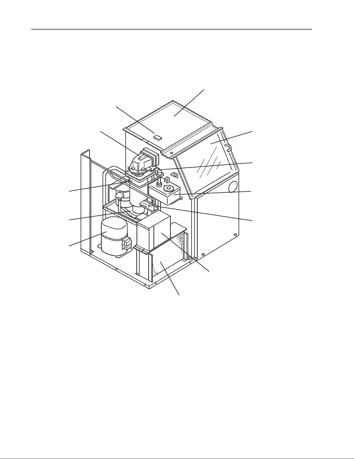
A. Construction
1. F-300BAF
Bin Control *
Ice Storage Bin
Evaporator
Gear Motor
Compressor
Spout
Sliding Door
Control Water Valve
Reservoir
Expansion Valve
Control Box
Air-cooled Condenser
*The switch actuator is located in the ice storage bin.
6
Page 7
B. Ice Making Unit
7
Page 8
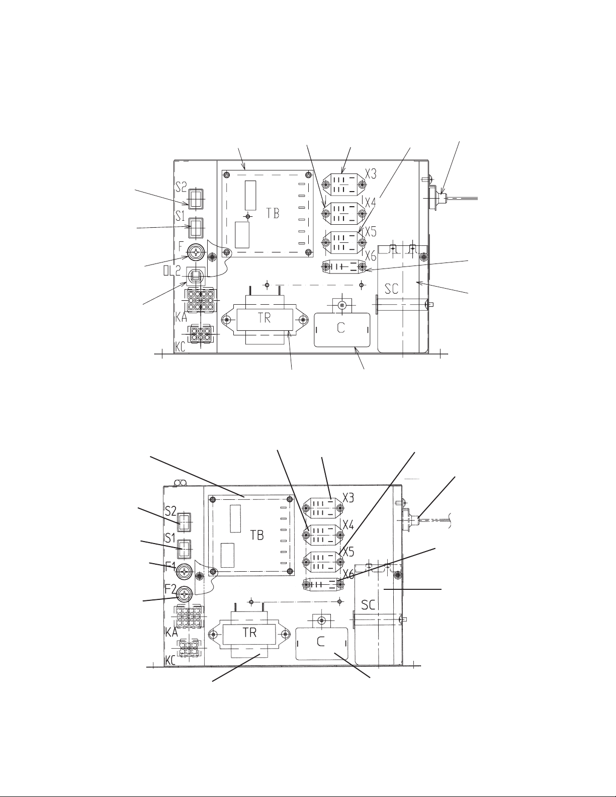
C. Control Box Layout
TRANSFORMER
CAPACITOR
GEAR MOTOR
START
CAPACITOR
FLUSH
RELAY
PRESSURE
SWITCH
CIRCUIT
PROTECT
RELAY
WATER
CONTROL
RELAY
GEAR MOTOR
PROTECT
RELAY
CONTROL
TIMER
FLUSH
SWITCH
POWER
SWITCH
CONTROL BOARD
FUSE (1A)
CIRCUIT
BREAKER
GEAR MOTOR
1. F-300BAF
a) Auxiliary Code K-1 and Earlier
b) Auxiliary Code K-2 and L-0
CONTROL TIMER
FLUSH SWITCH
POWER SWITCH
CONTROL BOARD
FUSE (1A)
GEAR MOTOR
FUSE (1.5A)
Note: The above component names are identical with the wiring label, but not with
TRANSFORMER
the parts list.
GEAR MOTOR
PROTECT RELAY
WATER CONTROL
RELAY
CAPACITOR - GEAR
MOTOR
CIRCUIT PROTECT
RELAY
PRESSURE SWITCH
FLUSH RELAY
START CAPACITOR
8
Page 9
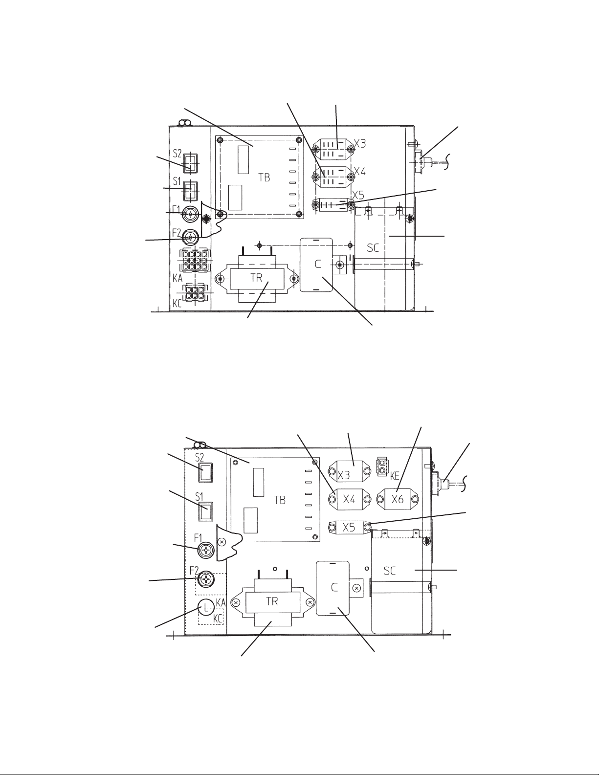
c) Auxiliary Code L-1 and M-0
CONTROL TIMER
FLUSH SWITCH
POWER SWITCH
CONTROL BOARD
FUSE (1A)
GEAR MOTOR
FUSE (1.5A)
GEAR MOTOR
PROTECT RELAY
TRANSFORMER
WATER CONTROL
RELAY
PRESSURE SWITCH
FLUSH RELAY
START CAPACITOR
CAPACITOR - GEAR
MOTOR
d) Auxiliary Code M-1 and Later
GEAR MOTOR
CONTROL TIMER
FLUSH SWITCH
POWER SWITCH
CONTROL BOARD
FUSE (1A)
GEAR MOTOR
FUSE (1.5A)
BIN CONTROL
SAFETY SWITCH
LAMP
TRANSFORMER
PROTECT RELAY
WATER CONTROL
RELAY
CAPACITOR - GEAR
MOTOR
SAFETY RELAY
PRESSURE SWITCH
FLUSH RELAY
START CAPACITOR
Note: The above component names are identical with the wiring label, but not with
the parts list.
9
Page 10

D. Timer Board
1. Solid-State Timer Board Control
• A HOSHIZAKI exclusive solid-state sequence timer board is employed in Hoshizaki selfcontained flaker icemakers.
• All models are pre-tested and factory-adjusted.
CAUTION
1. Fragile, handle very carefully.
2. The timer board contains CMOS (Complementary Metal-Oxide
Semiconductor) integrated circuits, which are susceptible to failure due to
static discharge. It is especially important to use an anti-static wrist strap
when handling or replacing the board.
3. Do not touch the electronic devices on the board or the back of the board to
prevent damage to the board.
4. Do not change wiring and connections. Especially, never misconnect
terminals.
5. Do not fix the electronic devices or parts on the board in the field. Always
replace the whole board assembly if it goes bad.
The timer board provides the following safeguards:
• Provides component protection during low water supply.
• Purges remaining ice in the evaporator.
• Provides short cycle protection for the compressor.
10
Page 11

E. Sequence of Operation
Hoshizaki utilizes a solid state timer board to switch the components on and off as
needed. The sequence is as follows:
1. Startup
Flush switch in "ICE" position, power switch in "ON" position. FR energizes.
2. Fill Cycle
WV opens and the reservoir fills with water until UF/S closes. Note: GM will not start
unless UF/S is closed. For details, see "IV. Service Diagnosis".
3. Ice Purge Cycle (60 seconds)
WCR energizes, closing the low water safety circuit and de-energizing WV. GMR
energizes (clear relay located on TB). GM starts and GMPR energizes. GM runs for 60
seconds to clear any ice from the evaporator.
Note: Low water safety circuit is terminals 3 and 4 on TB.
4. Freeze Cycle (Ice Making Process)
CR energizes (black relay located on TB). Comp and FMS energize. As the water in the
evaporator cools, ice starts forming within 4 to 6 minutes. This time frame depends on
the inlet water and ambient temperature conditions.
UF/S and LF/S operate WV as needed to continue the ice making process. This
continues until BC shuts the ice maker down or power is turned off to the unit.
5. Shutdown:
BC activates (opens). FR de-energizes, FWV energizes. Approximately 90 seconds after
BC activates, Comp and FMS de-energize, one minute later GMPR de-energizes and
GM stops.
Legend: BC–bin control; Comp–compressor; CR–compressor relay; FMS–self-
contained fan motor; FR–flush relay; FWV–flush water valve; GM–gear motor;
GMPR–gear motor protect relay; GMR–gear motor relay; LF/S–lower float
switch; TB–timer board; UF/S–upper float switch; WCR–water control relay;
WV–inlet water valve.
F. Ice Production Check
To check production, prepare a bucket or pan to catch the ice and a set of scales to
weigh the ice. After the unit has operated for 10 to 20 minutes, catch the ice production
for 10 minutes. Weigh the ice to establish the batch weight. Multiply the batch weight by
144 for the total production in 24 hours.
11
Page 12
If refill achieved, icemaking
cycle starts and timers
are reset.
4. Low Water Safety
Refill Cycle
UF/S closes terminating
90 sec TC.
60 sec. timer
90 sec. timer
If refill > 90 sec. TC
GM de-energized
GMPR de-energized
UF/S open
90 sec. TC exceeded
LF/S closed
UF/S closed
90 sec. TC ended
Comp de-energized
WCR de-energized
WV continues
FMS de-energized
WCR energized
FR continues
WV continues
WV continues
WV de-energized
Comp continues
GM continues
GM continues
Comp continues
GMPR continues
FMS continues
GM continues
FR continues
FMS continues
GMPR continues
FR continues
GMPR continues
FR continues
5. Compressor and fan
motor energize. Ice
production begins in 4
to 6 minutes.
60 seconds
4. Bin control proximity switch
closes. Reservoir fills. LF/S
and UF/S close. Gear motor
starts 6.7 seconds later.
6.7 sec.
Comp energized
FMS energized
LF/S and UF/S close
WCR energized
BC closed
FR energized
GM continues
WV de-energized
WV energized
GMPR continues
GM energized
FWV de-energized
WCR continues
GMPR energized
FR continues
FR continues
UF/S open
LF/S open
90 sec. TC started
WCR de-energized
WV energized
Comp continues
LF/S opens
initiating refill
60 sec. timer
and 90 sec. TC
Comp energized
FMS energized
WCR continues
GM continues
GMPR continues
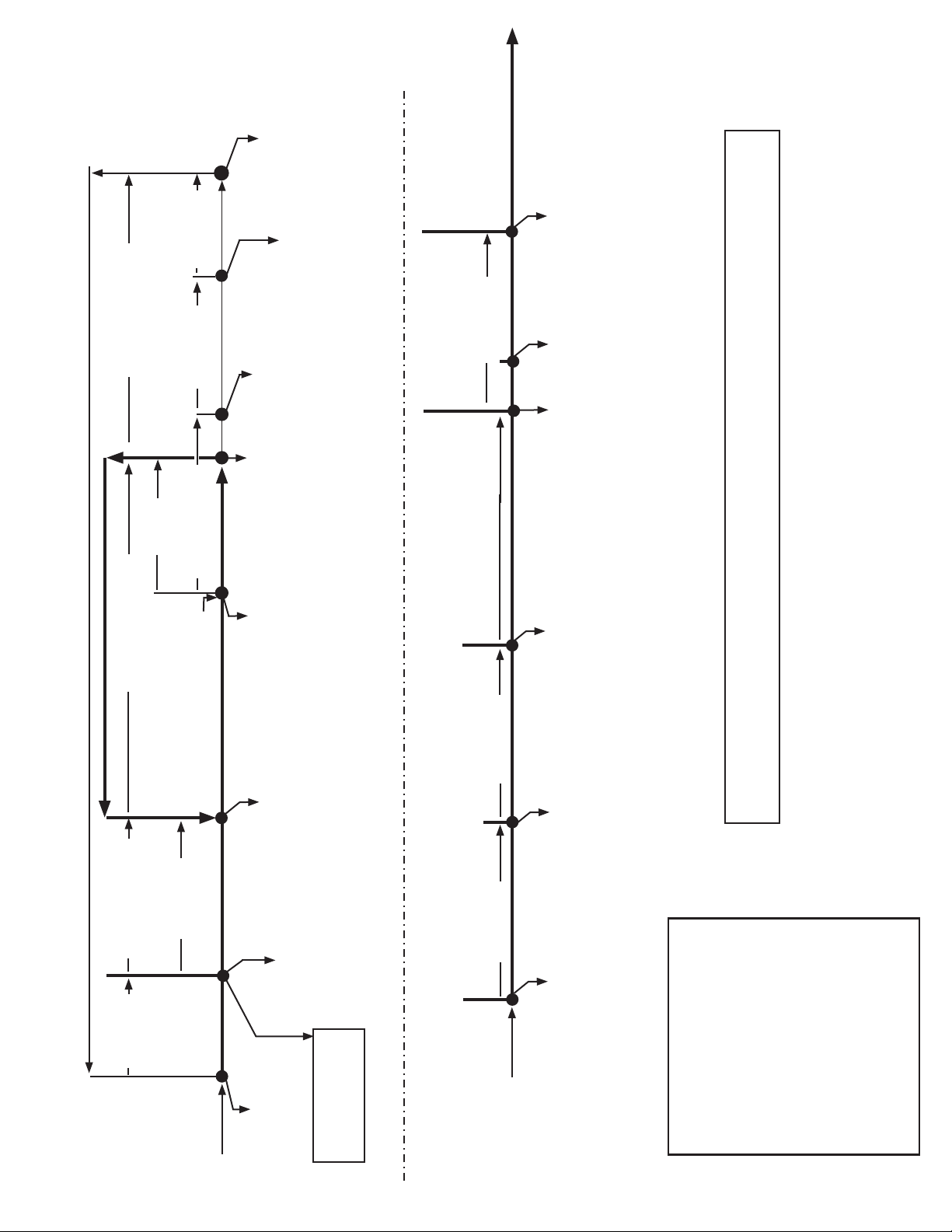
3. Icemaking Cycle
2. Ice Purge Cycle
F-300BAF, F-500BAF Sequence Flow Chart and Component Operation
LF/S closed
UF/S closed
WCR energized
WV de-energized
GM continues
FR continues
GM energized
FMS continues
GMPR energized
GMPR continues
FR continues
FR continues
3. Gear motor de-energizes
and unit is "OFF"
GM de-energized
GMPR de-energized
FWV continues
60 seconds
2. Compressor and fan motor
de-energize, gear motor
continues running.
Comp de-energized
FMS de-energized
GM continues
90 seconds
BC open
FR de-energized
1. Bin control proximity switch
opens to stop ice production.
WCR de-energized
GMPR continues
FWV energized
FWV continues
Comp continues
FMS continues
GM continues
GMPR continues
Components Energized when the Flush Switch is in the FLUSH Position
The FLUSH position is used when cleaning and sanitizing the machine. When in the FLUSH position, power is
supplied to the flush valve. This allows cleaner and sanitizer to drain from the evaporator assembly.
1. Startup
1. Fill Cycle
Flush switch in "ICE"
Power switch "ON"
FR energized
WCR de-energized
WV energized
Low water safety ciruit
closed. (Terminals 3
and 4 on timer board)
Bin control operation
12
2. Shutdown & Restart
Legend:
BC - bin control
Comp - compressor
FMS - self-contained fan motor
FR - flush relay
FWV - flush water valve
GM - gear motor
GMPR - gear motor protect relay
LF/S - lower float switch
TC - timer control
UF/S - upper float switch
WCR - water control relay
WV - inlet water valve
Page 13
III. Technical Information
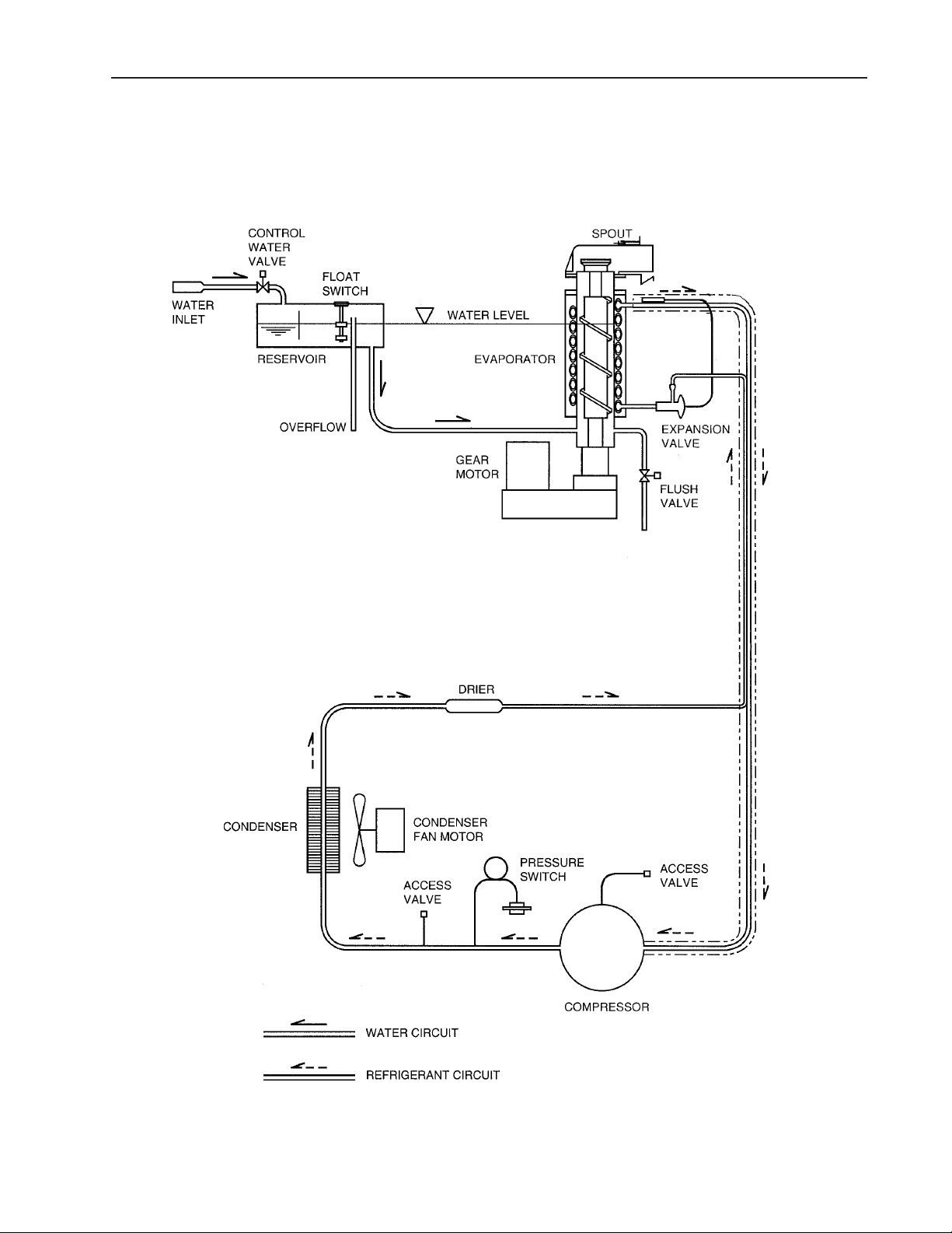
A. Water Circuit and Refrigeration Circuit
F-300BAF
13
Page 14
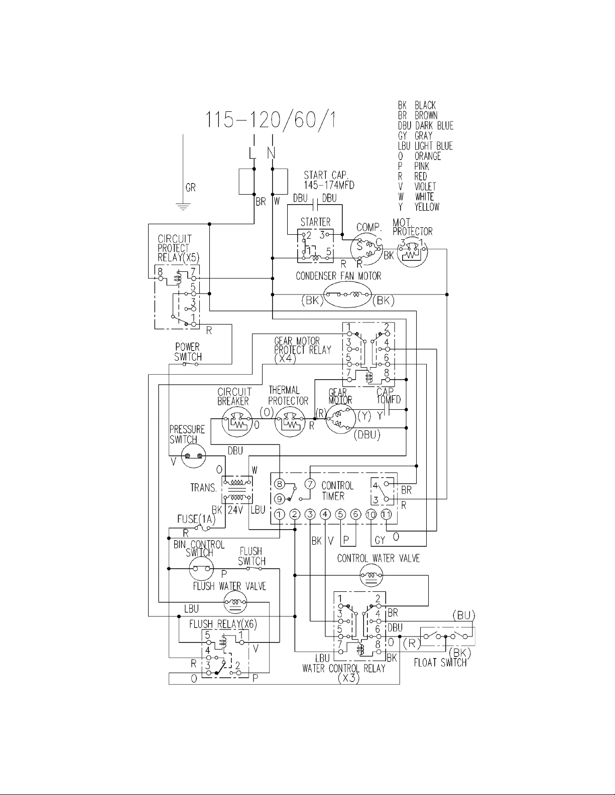
B. Wiring Diagram
1. Auxiliary Code K-1 and Earlier
14
F-300BAF
Page 15
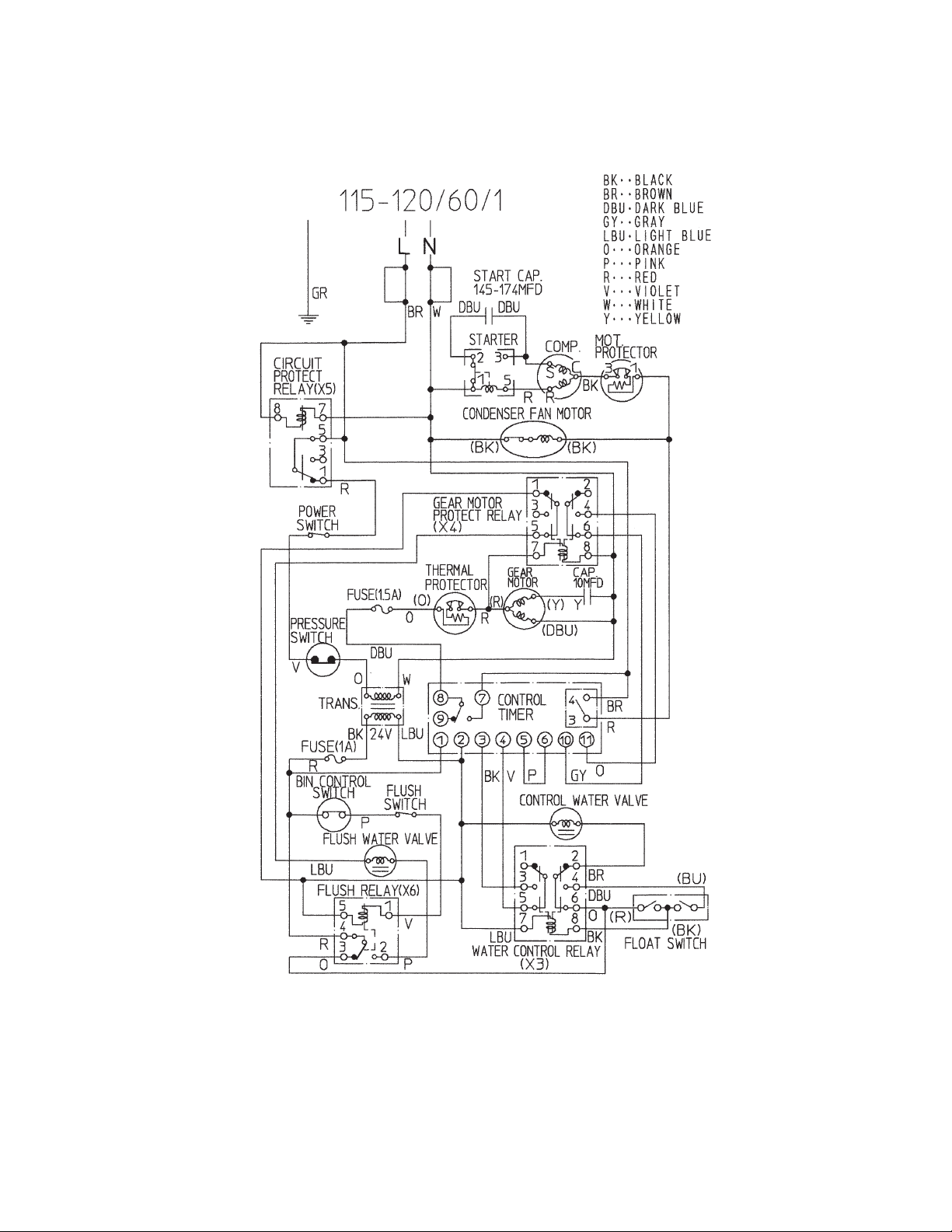
2. Auxiliary Code K-2 and L-0
15
F-300BAF
Page 16

3. Auxiliary Code L-1 and M-0
16
F-300BAF
Page 17

4. Auxiliary Code M-1 and Later
17
F-300BAF
Page 18

C. Sequence of Electrical Circuit
1. Fill Cycle
When power switch is moved to "ON" position, water is supplied to reservoir.
18
F-300BAF
Page 19

2. Ice Purge Cycle
When reservoir has filled, gear motor starts.
19
F-300BAF
Page 20

3. Freeze Cycle
Compressor and condenser fan motor start about 60 sec. after gear motor starts.
20
F-300BAF
Page 21

4. Shutdown
Compressor and condenser fan motor stop about 90 sec. after bin control operates, gear
motor stops about 60 sec. later. Flush water valve then operates.
21
F-300BAF
Page 22

5. Cleaning - Flush Switch
Compressor and condenser fan motor stop about 90 sec. after manually moving flush
switch to FLUSH position. Gear motor stops about 60 sec. later. Flush water valve then
operates.
22
F-300BAF
Page 23

6. Low Water Safety
If upper float switch fails to close, water valve remains open until upper float switch
closes and water control relay energizes.
23
F-300BAF
Page 24

7. Spout Safety Switch
When saftey switch is activated, the safety switch relay operates, and the icemaker does
not run.
24
F-300BAF
Page 25

8. High Pressure Switch
In case of high pressure, pressure switch shuts down unit.
25
F-300BAF
Page 26

D. Performance Data
APPROXIMATE Ambient Water Temp. (°F)
ICE PRODUCTION Temp. (°F)
PER 24 HR. 70 *303 *(137) 290 (131) 278 (126)
80 267 (121) 256 (116) 246 (112)
90 236 (107) *232 *(105) 218 (99)
lbs./day (kg/day) 100 209 (95) 201 (91) *188 *(85)
APPROXIMATE ELECTRIC 70 *667 -- 668 -- 669 -CONSUMPTION 80 670 -- 671 -- 672 --
90 673 -- *674 -- 681 -watts 100 688 -- 695 -- *702 -APPROXIMATE WATER 70 *36 *(137) 35 (131) 33 (126)
CONSUMPTION PER 24 HR. 80 32 (121) 31 (116) 30 (112)
90 28 (107) *28 *(105) 26 (99)
gal./day (l/day)
100 25 (95) 24 (91) *23 *(85)
EVAPORATOR OUTLET TEMP. 70 *19 *(-7) 19 (-7) 19 (-7)
80 19 (-7) 22 (-6) 22 (-6)
90 22 (-6) *22 *(-6) 26 (-4)
°F (°C) 100 26 (-4) 26 (-4) *26 *(-4)
HEAD PRESSURE 70 *250 *(17.5) 250 (17.5) 250 (17.5)
80 280 (19.7) 280 (19.7) 280 (19.7)
90 311 (21.9) *311 *(21.9) 311 (21.9)
PSIG (kg/cm²G)
100 351 (24.7) 351 (24.7) *351 *(24.7)
SUCTION PRESSURE 70 *35 *(2.5) 35 (2.5) 35 (2.5)
80 37 (2.6) 37 (2.6) 37 (2.6)
90 39 (2.7) *39 *(2.7) 39 (2.7)
PSIG ( kg/cm²G )
100 43 (3.0) 43 (3.0) *43 *(3.0)
TOTAL HEAT OF REJECTION 3178 BTU/h (AT 90°F /WT 70°F)
Note: The data without *marks should be used for reference.
507090
1. F-300BAF
We reserve the right to make changes to specifications and design without prior notice.
26
Page 27

IV. Service Diagnosis
A. Diagnostic Procedure
This diagnostic procedure is a sequence check that allows you to diagnose the electrical
system and components under normal operating conditions of 70°F or warmer air and
50°F or warmer water temperatures. Before proceeding, check for correct installation,
proper voltage per unit nameplate and adequate water supply.
1) Unplug the unit from the electrical outlet and access the control panel.
2) Plug the unit back in. Make sure the flush switch is in the ICE position, then place the
power switch in the ON position.
3) Fill Cycle – The water valve energizes. The reservoir begins to fill and the lower float
switch closes. Nothing occurs at this time. The reservoir continues to fill and the upper
float switch closes, energizng the water control relay. When the water control relay
energizes, the inlet water valve de-energizes and the low water safety circuit closes to
the timer board. Diagnosis: Check that the water valve fills the reservoir. If not, check
for clogged water filters, clogged water valve screen, power supply to the unit, power
circuit to the water valve (power switch, high pressure switch, transformer, safety switch,
safety relay contacts, fuse, bin control, flush switch, flush relay, flush relay contacts,
float switch, water control relay contacts), and the coil on the water valve.
3) Ice Purge Cycle – (short cycle protection) The gear motor and the gear motor protect
relay energize, and the 60 second compressor short cycle protection timer starts.
Diagnosis: Check that the gear motor starts. If not, check the low water safety circuit
on terminals 3 and 4 on the timer board, check for 120 volts on the gear motor relay
terminal 8 on the timer board, check the gear motor fuse, thermal protector, and gear
motor windings. If the gear motor starts but the auger does not turn: check the gear
motor coupling between the auger and the gear motor. If the compressor starts the
same time the gear motor starts: Check the compressor relay on the timer board (the
black relay on the timer board is the compressor relay).
4) Freeze Cycle – The compressor and fan motor energize, the gear motor, gear motor
protect relay, flush switch relay, and the water control relay remain energized. Ice
production begins 4 to 6 minutes after the compressor and fan motor start depending
on ambient and water conditions. Diagnosis: Check that the compressor and fan
motor are running. If not, check for 120 volts on the compressor relay terminal 4 on the
timer board (the black relay on the timer board is the compressor relay), check for 120
volts on the gear motor protect relay, check gear motor relay contacts 4 and 6, check
voltage on the compressor terminals, check the internal overload (motor protector), the
compressor capacitors, and voltage to the fan motor and fan capacitor.
27
Page 28

5) Refill/Low Water Safety Cycle – As ice is produced, the water level in the reservoir
drops. As it drops, the upper float switch and lower float switch open. The upper float
switch opens first. Nothing occurs at this time. When the lower float switch opens, the
refill begins. The water control relay de-energizes, the low water safety circuit opens
(terminals 4 and 6 on the water control relay, 3 and 4 on the timer board), a 90 second
countdown timer begins on the timer board, and the inlet water valve energizes. The
compressor, fan motor and gear motor continue to run. The upper float switch now
has 90 seconds to close before the low water safety timer terminates and shuts down
the unit. Once the upper float switch closes, the water control relay energizes, the
inlet water valve de-energizes and the low water safety 90 second countdown timer
terminates. Diagnosis – Check that the water fill begins. If not, check the lower float
switch, voltage to the inlet water valve, the water control relay, water supply, filters, and
inlet water valve screen.
7) Shutdown – The bin fills and activates the bin control proximity switch. 90 seconds
later the compressor and fan motor de-energize, then 60 seconds later the gear motor
de-energizes. Diagnosis: Check that the bin control paddle is activated and that
the proximity switch opens. If the compressor and gear motor fail to stop, check the
proximity switch and timer board relays.
28
Page 29

B. Diagnostic Charts
1. No Ice Production
Problem Possible Cause Remedy
[1] The icemaker will not
start. (fill cycle, water
valve)
a) Power Supply 1. Off. 1. Turn on.
Power cord
2.
unplugged.
3. Loose connection. 3. Tighten.
4. Bad contacts. 4. Check for contintinuity and
5. Blown fuse. 5. Replace.
b) Power Switch
(Control Box)
c) High Pressure Switch 1. Dirty air filter or
d) Transformer 1. Coil winding opened. 1. Replace.
e) Spout Safety Switch
and Relay
f) Fuse (Control Box) 1. Blown. 1. Check for short circuit and
g) Bin Control 1. Actuator sticking. 1. Adjust or replace.
h) Flush Switch 1. FLUSH position. 1.Move to ICE position.
i) Flush Switch Relay 1. Coil open. 1. Replace.
1. OFF position. 1. Move to ON position.
Bad contacts. 2. Check for continuity and
2.
condenser.
Ambient or condenser
2.
water temperature too
warm.
3. Condenser water
pressure too low or off.
(water-cooled model
only)
4. Water regulating valve
set too high. (watercooled model only)
5. Fan not rotating. 5.See "3. [1] a) Fan Motor.”
6. Refrigerant
overcharged.
7. Refrigerant line or
components plugged.
8. Bad contacts. 8. Check for continuity and
9. Loose connections. 9. Tighten.
1. Bin control not
activating.
2. Proximity switch open. 2. Replace.
2. Bad contacts. 2. Check for continuity and
2. Plug into receptacle.
replace.
replace.
1. Clean.
2. Reduce temperature.
3. Check and get
recommended pressure.
4. Adjust it lower.
6. Recharge.
7. Clean and replace drier.
replace.
1. Check bin control actuator
and proximity switch.
replace.
replace.
29
Page 30

Problem Possible Cause Remedy
j) Water Control Relay 1. Bad contacts. 1. Replace.
Open coil. 2. Replace.
2.
k) Water Valve 1. Coil winding opened. 1. Replace.
l) Shut-off Valve 1. Closed. 1. Open.
Water failure. 2. Wait until water is
2.
supplied.
Water does not stop,
[2]
and the gear motor
will not start.
Water has been
[3]
supplied, but the gear
motor will not start.
Gear motor starts,
[4]
but compressor will
not start or operates
intermittently.
m)Plug and Receptacle
(Control Box)
a) Float Switch 1. Bad contacts. 1. Check for continuity and
b) Water Control Relay 1. Contact fused. 1. Replace.
c) Flush Water Valve 1. Valve seat clogged
d) Hoses 1. Disconnected. 1. Connect.
a) Bin Control 1. Open 1.Bin full, check for
b) Water Control Relay 1. Low water safety
c) Control Timer
(Printed Circuit Board)
d) Gear Motor Fuse 1. Blown. 1. Check gear motor
e) Gear Motor Thermal
Protector
f) Gear Motor 1. Open windings. 1. Replace gear motor.
a) Gear Motor Protect
Relay
b) Timer Board Relay 1. Bad contacts. 1. Check for continuity and
c) Starter 1. Bad contacts. 1. Check for continuity and
d) Start Capacitor or Run
Capacitor
1. Disconnected. 1.Connect.
Loose terminal. 2. Repair terminal
2.
connection.
replace.
2. Float does not move
freely.
2. Coil winding opened. 2. Replace.
and water leaking.
circuit open
(bad conacts ).
1. Fails to operate gear
motor relay.
1. Open. 1. Check gear motor
Locked bearings 1. Replace gear motor.
2.
1. Open coil. 1. Replace.
Open contacts. 2. Replace.
2.
2. Coil winding opened. 2. Replace timer.
Coil winding opened. 2. Replace.
2.
3. Loose connections. 3. Tighten.
1. Defective. 1. Replace.
2. Clean or replace.
1. Clean or replace.
continuity on proximity
switch.
1. Replace relay.
1. Check water control relay
circuit.
amperage, bearing
wear (see "V. F. 1. Upper
Bearing Wear Check"),
supply voltage.
bearings, voltage supply.
replace.
replace.
30
Page 31

Problem Possible Cause Remedy
e) Compressor 1. Loose connections. 1. Tighten.
[5] Gear motor and
compressor start, but
no ice is produced.
Motor winding opened
2.
or grounded.
3. Compressor locked
and motor protector
tripped.
f) Power Supply 1. Circuit ampacity too
low.
a) Refrigerant Line 1. Gas leaks. 1. Check for leaks with a
2. Refrigerant line
clogged.
2. Replace.
3. Replace compressor.
1. Install a larger-sized
circuit.
leak detector. Replace
drier and charge with
refrigerant. Refrigerant
charge is marked on
nameplate or rating label.
2. Replace the clogged
component.
2. Low Ice Production
Problem Possible Cause Remedy
[1] Low ice production. a)Refrigerant Line 1. Gas leaks. 1.See "2. [5] a) Refrigerant
Line."
b)High-Side Pressure Too
High
c) Expansion Valve (not
adjustable)
2. Refrigerant line
clogged.
3. Overcharged. 3. Recharge.
1. Dirty air filter or
condenser.
Ambient or condenser
2.
water temperature too
warm.
3. Condenser water
pressure too low or off.
[water-cooled model
only]
4. Fan, slow rpm. 4.See "3. [1] a) Fan Motor".
5. Water regulating valve
clogged. [water-cooled
model only]
1. Low-side pressure too
low.
2. Low-side pressure too
high.
2. Replace the clogged
component.
1. Clean.
2. Reduce temperature.
3. Check and get recommended pressure.
5. Clean.
1. Replace.
2. See if expansion valve
bulb is mounted properly,
and replace the valve if
necessary.
31
Page 32

3. Other
Problem Possible Cause Remedy
[1] Abnormal noise a)Fan Motor 1. Bearing worn out. 1. Replace.
Fan blade deformed. 2. Replace fan blade.
2.
Overflow from
[2]
reservoir (water does
not stop).
[3] Gear motor protector
operates frequently or
fuse blows frequently.
3. Fan blade does not
move freely.
b)Compressor 1. Bearings worn out, or
cylinder valve broken.
2. Mounting pad out of
position.
c) Refrigerant Lines 1. Rub or touch lines or
other surfaces.
d)Gear Motor 1. Bearing or gear worn
out / damaged.
e)Evaporator 1. Low refrigerant
pressures.
Expansion valve bad. 2.Replace.
2.
3. Evaporator bad. 3.Replace.
4. Scale on inside wall of
freezing cylinder.
a)Water Supply 1. Water pressure too
high.
b)Water Valve 1. Diaphragm does not
close.
c) Float Switch 1.Bad contacts. 1. Check for continuity and
d)Water Control Relay 1. Bad contacts. 1. Replace
a)Power Supply Voltage 1. Too high or too low. 1. Connect the unit to a
b)Evaporator Assembly 1. Bearings or auger
worn out.
c) Bin Control 1. Bad contacts. 1. Check for continuity and
Actuator does not
2.
move freely.
3. Replace.
1. Replace.
2. Reinstall.
1. Replace or separate.
1. Replace.
1. Check charge, check for
possible leak, repair,
re-charge.
4. Use "SCALE AWAY" or
"LIME-A-WAY" solution to
clean periodically. If the
water is found hard by
testing, install a softener.
1. Install a pressure reducing
valve.
1. Clean or replace.
replace.
power supply of proper
voltage.
1. Replace bearings or
auger.
replace.
2. Clean shaft and its
corresponding holes or
replace bin control.
32
Page 33

V. Removal and Replacement of Components
IMPORTANT
Ensure all components, fasteners and thumbscrews are securely in place after
the equipment is serviced.
IMPORTANT
1. The Polyol Ester (POE) oils used in R-404A units can absorb moisture
quickly. Therefore it is important to prevent moisture from entering the system
when replacing or servicing parts.
2. Always install a new drier every time the sealed refrigeration system is
opened.
3. Do not leave the system open for longer than 15 minutes when replacing or
servicing parts.
A. Service for Refrigerant Lines
1. Refrigerant Recovery
The icemaker unit is provided with refrigerant access valves. Using proper refrigerant
practices recover the refrigerant from the access valves and store it in an approved
container. Do not discharge the refrigerant into the atmosphere.
2. Evacuation and Recharge [R-404A]
1) Attach service manifold hoses and a vacuum pump to the system. Be sure to connect
charging hoses to both high-side and low-side access valves.
IMPORTANT
The vacuum level and vacuum pump may be the same as those for current
refrigerants. However, the rubber hose and gauge manifold to be used for
evacuation and refrigerant charge should be exclusively for POE oils.
2) Turn on the vacuum pump. Never allow the oil in the vacuum pump to flow backward.
3) Allow the vacuum pump to pull down to a 29.9" Hg vacuum. Evacuating period
depends on pump capacity.
4) Close the low-side valve and high-side valve on the service manifold.
5) Disconnect the vacuum pump, and attach a refrigerant service cylinder to the highside line. Remember to loosen the connection, and purge the air from the hose. See
the nameplate for the required refrigerant charge. Hoshizaki recommends only virgin
refrigerant or reclaimed refrigerant which meets ARI Standard No. 700-88 be used.
6) A liquid charge is recommended for charging an R-404A system. Invert the service
cylinder and place it on scales. Open the high-side, service manifold valve.
7) Allow the system to charge with liquid until the proper charge weight is met.
33
Page 34

8) If necessary, add any remaining charge to the system through the low-side. Use a
throttling valve or liquid dispensing device to add the remaining liquid charge through
the low-side access port with the unit running.
9) Close the two refrigerant access valves, and disconnect the service manifold hoses.
10) Cap the access valves to prevent a possible leak.
B. Brazing
WARNING
1. Refrigerant R-404A itself is not flammable at atmospheric pressure and
temperatures up to 176°F.
2. Refrigerant R-404A itself is not explosive or poisonous. However, when
exposed to high temperatures (open flames) R-404A can be decomposed to
form hydrofluoric acid and carbonyl fluoride both of which are hazardous.
3. Always recover the refrigerant and store it in an approved container. Do not
discharge the refrigerant into the atmosphere.
4. Do not use silver alloy or copper alloy containing arsenic.
5. Do not use R-404A as a mixture with pressurized air for leak testing.
Refrigerant leaks can be detected by charging the unit with a little refrigerant,
raising the pressure with nitrogen and using an electronic leak detector.
Note: All brazing connections are clear-paint coated. Use sandpaper to remove the
coating from the brazing connections before unbrazing the components.
34
Page 35

C. Removal and Replacement of Compressor
IMPORTANT
Always install a new drier every time the sealed refrigeration system is opened.
Do not replace the drier until after all other repair or replacement has been
made.
Note: When replacing a compressor with a defective winding, be sure to install the
new start capacitor and start relay supplied with the replacement compressor.
Due to the ability of the POE oil in the compressor to absorb moisture quickly,
the compressor must not be opened more than 15 minutes for replacement or
service. Do not mix lubricants of different compressors even if both are charged
with R-404A, except when they use the same lubricant.
1) Unplug the unit from the electrical outlet.
2) Remove the panels.
3) Recover the refrigerant and store it in an approved container.
4) Remove the terminal cover on the compressor and disconnect the compressor wiring.
5) Remove the hold-down bolts, washers and rubber grommets .
6) Remove the discharge and suction pipes
7) Remove the compressor. Unpack the new compressor package.
8) Attach the rubber grommets of the prior compressor.
9) Place the compressor in position and secure it using the bolts and washers.
10) Remove the drier, then place the new drier in position.
11) Remove plugs from the suction, discharge and process pipes.
12) Braze all fittings while purging with nitrogen gas flowing at a pressure of 3 to 4 PSIG.
13) Check for leaks using nitrogen gas (140 PSIG) and soap bubbles.
14) Evacuate the system, and charge it with refrigerant. See the nameplate for the required
refrigerant charge.
15) Connect the terminals and replace the terminal cover in its correct position.
16) Replace the panels in their correct positions.
17) Plug the unit back in.
35
Page 36

D. Removal and Replacement of Drier
IMPORTANT
Always install a new drier every time the sealed refrigeration system is opened.
Do not replace the drier until after all other repair or replacement has been
made.
1) Unplug the unit from the electrical outlet.
2) Remove the panels.
3) Recover the refrigerant and store it in an approved container.
4) Remove the drier, then place the new drier in position. Install the new drier with the
arrow on the drier in the direction of the refrigerant flow.
5) Braze all fittings while purging with nitrogen gas flowing at a pressure of 3 to 4 PSIG.
6) Check for leaks using nitrogen gas (140 PSIG) and soap bubbles.
7) Evacuate the system, and charge it with refrigerant. See the nameplate for the required
refrigerant charge.
8) Replace the panels in their correct positions.
9) Plug the unit back in.
E. Removal and Replacement of Expansion Valve
IMPORTANT
Sometimes moisture in the refrigeration circuit exceeds the drier capacity and
freezes up at the expansion valve. Always install a new drier every time the
sealed refrigeration system is opened. Do not replace the drier until after all
other repair or replacement has been made.
1) Unplug the unit from the electrical outlet.
2) Remove the panels.
3) Recover the refrigerant and store it in an approved container.
4) Remove the insulation and the expansion valve bulb on the suction line.
5) Remove the expansion valve cover and disconnect the expansion valve. Place the new
expansion valve in position.
6) Remove the drier, then place the new drier in position.
7) Braze all fittings while purging with nitrogen gas flowing at a pressure of 3 to 4 PSIG.
WARNING
Always protect the valve body by using a damp cloth to prevent the valve from
overheating. Do not braze with the valve body exceeding 250°F (121°C).
36
Page 37

8) Check for leaks using nitrogen gas (140 PSIG) and soap bubbles.
9) Evacuate the system, and charge it with refrigerant. See the nameplate for the required
refrigerant charge.
10) Attach the expansion valve bulb to the suction line in the same location as the previous
bulb. The bulb should be at the 12 o'clock position on the tube. Be sure to secure the
bulb with the clamp and holder and to insulate it.
11) Place the expansion valve cover in position.
12) Replace the panels in their correct positions.
13) Plug the unit back in.
37
Page 38

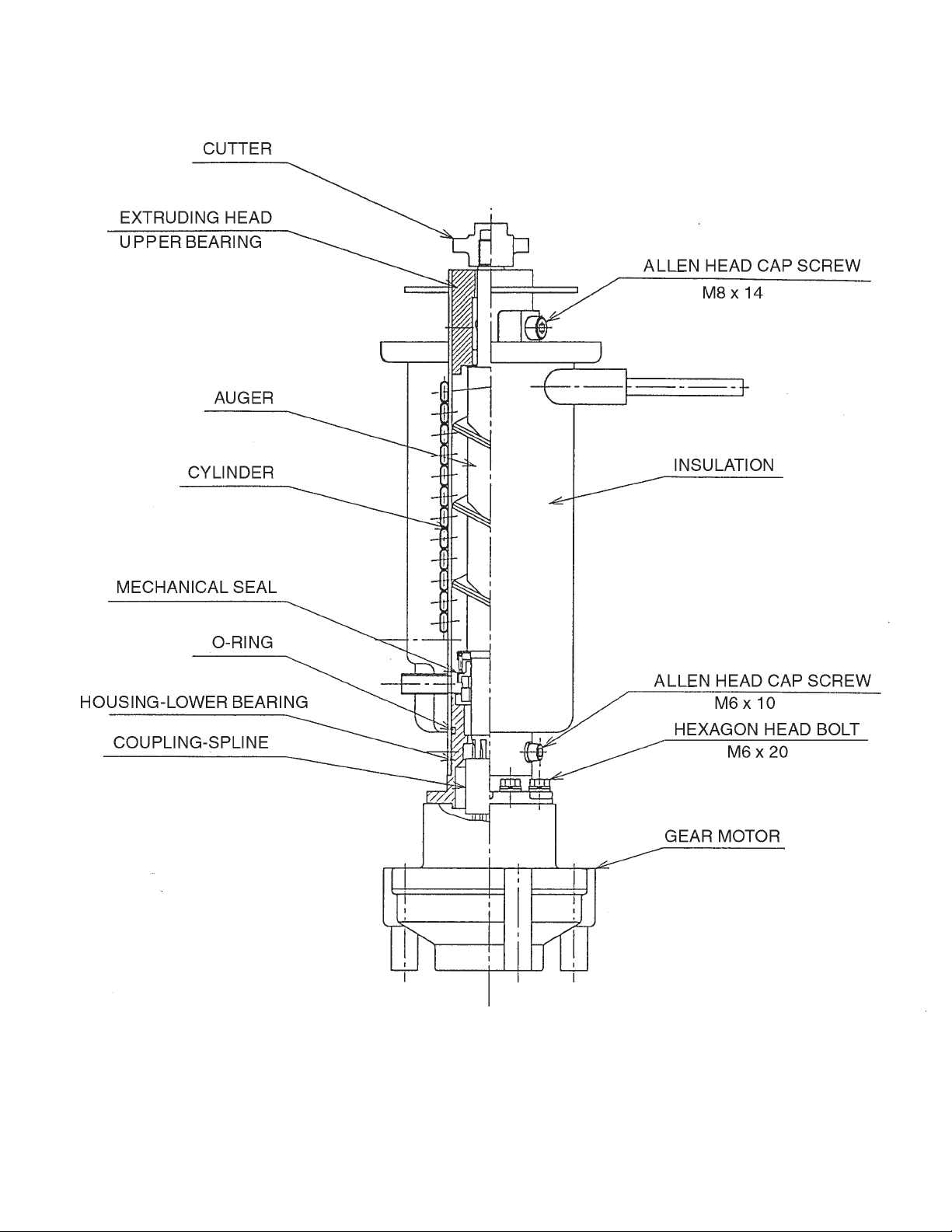
F. Removal and Replacement of Evaporator Assembly Components
CAUTION
Make sure that the saftey switch and spout are properly installed after making
repairs in the evaporator assembly. Failure to install the safety switch and spout
correctly could result in serious damage to the unit.
Safety Bracket A
Safety Switch
Drip Bracket
Channel
Drip Bracket
Safety Bracket B
Channel
Auger
Safety Switch Assembly
Safety Bracket A
Spout
Safety Bracket B
Spout
Drip Bracket
Cutter
Extruding Head
Upper Bearing
Spring Retainer
Mechanical Seal
O-Ring
Barrier
Gear Motor
Evaporator
Allen Head Cap Screw
Allen Head Cap Screw
with Washer
Housing-Lower Bearing
Coupling-Spline
Fig. 1
38
Page 39

1. Upper Bearing Wear Check
To ensure that the bearing inside the extruding head does not exceed the wear tolerance
of .02", follow the instructions below.
1) Unplug the unit from the electrical outlet.
2) Remove the panels.
3) Remove the thumbscrews and take off the
spout from the evaporator.
.02" Round Stock
or Pin Gauge
4) Loosen the cutter with a wrench and
remove it.
5) Grasp the top of the auger and move the
auger towards you and then try to insert a
.02" round stock or pin gauge in between
the back side of the auger shaft and the
bearing surface. Check several locations
around the auger shaft. If the gauge goes
between the shaft and the bearing at
any point or if the bearing is scratched
or cracked, both the top bearing in the
extruding head and the lower bearing in the
housing should be replaced. Instructions
for removing the extruding head and
housing are located later in this procedure.
Note: Replacing the bearing requires a bearing press adaptor. If one is not available,
replace the whole extruding head and housing.
6) Replace the cutter.
7) Replace the spout. Make sure that the drip bracket is in the channel and that safety
bracket B is behind safety bracket A. See Fig. 1.
Fig. 2
Auger
Extruding
Head
8) Replace the panels in their correct positions.
9) Plug the unit back in.
2. Removal and Replacement of Cutter
1) Unplug the unit from the electrical outlet.
2) Remove the panels.
3) Remove the thumbscrews and take off the spout from the evaporator.
4) Loosen the cutter with a wrench and remove it.
5) Install the new cutter.
6) Replace the spout. Make sure that the drip bracket is in the channel and that safety
bracket B is behind safety bracket A. See Fig.1.
7) Replace the panels in their correct positions.
8) Plug the unit back in.
39
Page 40

3. Removal and Replacement of Extruding Head
1) Unplug the unit from the electrical outlet.
2) Remove the panels.
3) Remove the thumbscrews and take off the spout from the evaporator.
4) Loosen the cutter with a wrench and remove it.
5) Remove the allen head cap screws and lift off the extruding head.
6) Place new extruding head in place and tighten down allen head cap screws. If the seals
on the allen head cap screws are RED, they must be replaced. If the seals are BLUE,
they may be re-used.
7) Replace the cutter and spout. Make sure that the drip bracket is in the channel and that
safety bracket B is behind safety bracket A. See Fig. 1.
8) Replace the panels in their correct positions.
9) Plug the unit back in.
4. Removal and Replacement of Auger
1) Drain water from the evaporator by using the flush switch.
2) Unplug the unit from the electrical outlet.
3) Remove the panels.
4) Remove the thumbscrews and take off the spout from the evaporator.
5) Loosen the cutter with a wrench.
6) Remove the allen head cap screws securing the extruding head. Using the cutter, lift out
the auger assembly.
7) Remove the cutter and extruding head from the auger and place on the new auger.
8) Install the new auger.
9) Replace the removed parts in the reverse order of which they were removed. When
replacing the spout, make sure that the drip bracket is in the channel and that safety
bracket B is behind safety bracket A. See Fig. 1.
10) Replace the panels in their correct positions.
11) Plug the unit back in.
5. Removal and Replacement of Evaporator
IMPORTANT
Always install a new drier every time the sealed refrigeration system is opened.
Do not replace the drier until after all other repair or replacement has been
made.
1) Remove the panels.
2) Drain water from the evaporator by using the flush switch.
3) Unplug the unit from the electrical outlet.
40
Page 41

4) Recover the refrigerant and store it in an approved container.
5) Remove the thumbscrews and take off the spout from the evaporator.
6) Disconnect the water hoses.
7) Remove the allen head cap screws securing the extruding head. Using the cutter, lift
out the auger assembly.
8) Remove the insulation and the expansion valve bulb on the suction line.
9) Disconnect the inlet and outlet tubing.
10) Remove the allen head cap screws securing the evaporator to the lower housing.
11) Lift off the evaporator.
12) Inspect the mechanical seal and O-ring prior to installing the new evaporator. The
mechanical seal consists of two parts. One moves along with the auger, and the other
is fixed on the lower housing. If the contact surfaces of these two parts are worn,
cracked or scratched, the mechanical seal may cause water leaks and should be
replaced. Instructions for removing the mechanical seal and lower housing are located
later in this procedure.
13) Make sure the lower mechanical seal is in place, then place the evaporator in position.
Secure the evaporator to the lower housing using the allen head cap screws.
14) Remove the drier, then place the new drier in position.
15) Braze all fittings while purging with nitrogen gas flowing at a pressure of 3 to 4 PSIG.
16) Check for leaks using nitrogen gas (140 PSIG) and soap bubbles.
17) Evacuate the system, and charge it with refrigerant. See the nameplate for the required
refrigerant charge.
18) Replace the removed parts in the reverse order of which they were removed. When
replacing the spout, make sure that the drip bracket is in the channel and that safety
bracket B is behind safety bracket A. See Fig. 1.
19) Replace the panels in their correct positions.
20) Plug the unit back in.
6. Removal and Replacement of Mechanical Seal and Lower Housing
6a. Mechanical Seal
1) Drain water from the evaporator by using the flush switch.
2) Unplug the unit from the electrical outlet.
3) Remove the panels.
4) Remove the thumbscrews and take off the spout from the evaporator.
5) Remove the allen head cap screws securing the extruding head. Using the cutter, lift
out the auger assembly.
6) The mechanical seal consists of two parts. One moves along with the auger, and the
other is fixed on the lower housing. If the contact surfaces of these two parts are worn,
cracked or scratched, the mechanical seal may cause water leaks and should be
replaced.
41
Page 42

7) Remove the allen head cap screws securing the evaporator to the lower bearing
housing.
8) Raise the evaporator up to access the lower housing.
9) Remove the O-ring and mechanical seal from the housing. If only replacing mechanical
seal, proceed to step 12).
WARNING
To help prevent water leaks, be careful not to damage the surfaces of the
O-ring or mechanical seal.
6b. Lower Housing
10) Remove the bolts securing the housing to the gear motor and remove the housing from
the gear motor. If inspection of the upper bearing inside the extruding head (see "F. 1.
Upper Bearing Wear Check") indicates that it is out of tolerance, replace both it and the
bearing inside the lower housing.
Note: Replacing the bearing requires a bearing press adaptor. If one is not available,
replace the whole extruding head and housing.
11) Mount the lower housing on the gear motor.
12) Install the O-ring and lower part of mechanical seal on the lower housing.
13 ) Lower the evaporator down and secure it to the lower housing.
14) Install the auger assembly with the upper part of the mechanical seal attached.
15) Replace the removed parts in the reverse order of which they were removed. When
replacing the spout, make sure that the drip bracket is in the channel and that safety
bracket B is behind safety bracket A. See Fig. 1.
16) Replace the panels in their correct positions.
17) Plug the unit back in.
7. Removal and Replacement of Gear Motor
1) Drain the water from the evaporator by using the flush switch.
2) Unplug the unit from the electrical outlet.
3) Remove the panels.
4) Remove the thumbscrews and take off the spout assembly from the evaporator.
5) Remove the bolts securing the lower housing to the gear motor. Lift the evaporator up
slightly.
6) Remove the bolts securing the gear motor.
7) Remove the wiring from the gear motor, then remove the gear motor.
8) Remove the barrier, gear motor bracket and coupling-spline from the old gear motor
and place on the new gear motor. Apply silicone over barrier screws.
9) Replace the removed parts in the reverse order of which they were removed. When
replacing the spout, make sure that the drip bracket is in the channel and that safety
bracket B is behind safety bracket A. See Fig. 1.
42
Page 43

10) Replace the panels in their correct positions.
11) Plug the unit back in.
G. Removal and Replacement of Fan Motor
1) Unplug the unit from the electrical outlet.
2) Remove the panels.
3) Remove the wire connectors from the fan motor leads.
4) Remove the fan motor bracket and fan motor.
5) Install the new fan motor.
6) Replace the fan motor bracket and the wire connectors.
7) Replace the panels in their correct positions.
8) Plug the unit back in.
H. Removal and Replacement of Inlet Water Valve
1) Unplug the unit from the electrical outlet.
2) Remove the panels.
3) Close the water supply line shut-off valve.
4) Disconnect the terminals from the water valve.
5) Loosen the fitting nut on the water valve inlet, and remove the water valve. Do not lose
the packings inside the fitting nut.
6) Remove the water supply hose from the water valve.
7) Install the new water valve.
8) Assemble the removed parts in the reverse order of the above procedure.
9) Open the water supply line shut-off valve.
10) Check for water leaks.
11) Replace the panels in their correct positions.
12) Plug the unit back in.
I. Removal and Replacement of Flush Water Valve
1) Unplug the unit from the electrical outlet.
2) Remove the panels and close the water supply line shut-off valve.
3) Remove the clamp and disconnect the water valve.
Note: Water may still remain inside the evaporator. Be sure to drain the water into the
drain pan.
4) Disconnect the terminals from the water valve.
5) Remove the water valve from the bracket.
6) Remove the drain pipe from the water valve.
7) Connect the drain pipe to the new water valve, and place the valve in position.
43
Page 44

8) Connect the hose to the water valve and secure it with the clamp.
9) Pour water into the reservoir, and check for water leaks.
10) Open the water supply line shut-off valve.
11) Plug the unit back in.
12) Move the flush switch to the "ICE" position.
13) Check for water leaks.
14) Move the flush switch to the "FLUSH" position, and make sure water is flushing.
15) Move the flush switch to the "ICE" position.
16) Replace the panels in their correct positions.
17) Plug the unit back in.
44
Page 45

VI. Cleaning and Maintenance
IMPORTANT
Ensure all components, fasteners and thumbscrews are securely in place after
any maintenance or cleaning is done to the equipment.
A. Cleaning and Sanitizing Instructions
WARNING
1. HOSHIZAKI recommends cleaning this unit at least once a year. More
frequent cleaning, however, may be required in some existing water
conditions.
2. To prevent injury to individuals and damage to the icemaker, do not use
ammonia type cleaners.
3. Always wear liquid-proof gloves to prevent the cleaning and sanitizing
solutions from coming into contact with skin.
1. Cleaning Solution
Dilute 4.8 fl. oz. (142 ml) of recommended cleaner Hoshizaki "Scale Away" or
"LIME-A-WAY" (Economics Laboratory, Inc.) with 0.8 gallons (3 l) of warm water. This is
a minimum amount. Make more solution if necessary.
IMPORTANT
For safety and maximum effectiveness, use the solution immediately after
dilution.
2. Cleaning Procedure
1) Unplug the unit from the electrical outlet then remove the front panel and the top panel.
2) Close the water supply line shut-off valve.
3) Remove all ice from the storage bin.
4) Move the flush switch to the "FLUSH" position.
5) Plug the unit back in and turn on the power
supply and drain out all water from the
water line.
6) Turn off the power supply.
Note: This unit is designed to start operating when the
reservoir is filled with water.
7) In the storage bin, remove the thumbscrews attaching spout (B), then remove spout (B)
and spout packing (B). See Fig. 3.
Thumbscrews
Spout Packing (B)
Fig. 3
Spout (B)
45
Page 46

8) Remove the thumbscrews attaching spout
(A) to the evaporator assembly and lift off
spout (A) and spout packing (A). See Fig 4.
Thumbscrews
Spout (A)
9) Pour the cleaning solution over the
extruding head until the evaporator
Evaporator Assembly
Spout (A) Packing
assembly and the reservoir are filled and
the solution starts to overflow into the drain
pan.
Fig. 4
Note: If there is excess scale on the extruding head, fill the evaporator assembly and
reservoir as described above, then use a clamp on the reservoir hose between
the reservoir and evaporator assembly to block flow. Pour additional cleaning fluid
over the extruding head until the evaporator assembly is completely full.
10) Using the thumbscrews, replace spouts (A) and (B) and spout packings (A) and (B) in
their correct positions.
11) Allow the icemaker to sit for about 10 minutes before operation. If you placed a clamp
on the reservoir hose in step 9, remove it before operation.
12) Move the flush switch to the "ICE" position, then turn on the power supply. Replace the
top panel and the front panel in their correct positions. Make ice using the solution until
the icemaker stops making ice.
13) Remove the front panel.
14) Move the flush switch to the "FLUSH" position to drain the remainder of the solution.
15) After the solution is drained, move the flush switch to the "ICE" position.
16) Replace the front panel in its correct position.
17) Open the water supply line shut-off valve, and supply water to the reservoir.
18) When the gear motor starts, remove the top panel and front panel. Turn off the power
supply.
19) Drain out all water from the water line. See 4) through 6).
3. Sanitizing Solution
Dilute 2.5 fl. oz. (74 ml or 5 tbs) of a 5.25% sodium hypochlorite solution (chlorine
bleach) with 5 gallons (19 l) of warm water.
IMPORTANT
For safety and maximum effectiveness, use the solution immediately after
dilution.
46
Page 47

4. Sanitizing Procedure - Initial
1) Close the water supply line shut-off valve.
2) In the storage bin, remove the thumbscrews attaching spout (B), then remove spout (B)
and spout packing (B).
3) Remove the thumbscrews attaching spout (A) to the evaporator assembly and
lift off spout (A) and spout packing (A), and the cylinder packing.
4) Pour the sanitizing solution over the extruding head until the evaporator assembly and
the reservoir are filled and the solution starts to overflow into the drain pan.
5) Remove the thumbscrews attaching the bin
control assembly to the inside of the bin
Bracket
Thumbscrews
top panel. See Fig. 5.
6) Remove the snap pin, shaft and actuator.
7) Remove the sliding door.
Snap Pin
8) Soak the removed parts in .25 gallons (1 l)
Shaft
Actuator
of sanitizing solution for 10 minutes then
wipe them down.
Fig. 5
9) Rinse the parts thoroughly.
IMPORTANT
If the solution is left on these parts, they will rust.
10) Replace all parts in their correct positions.
11) Move the flush switch to the "ICE" position, then turn on the power supply. Replace the
top panel and the front panel in their correct positions. Make ice using the solution until
the icemaker stops making ice.
5. Sanitizing Procedure - Final
1) Remove the front panel and the top panel, then turn off the power supply.
2) Move the flush switch to the "FLUSH" position.
3) Turn on the power supply and drain out all water from the water line.
4) Turn off the power supply.
Note: This unit is designed to start operating when the reservoir is filled with water.
5) In the storage bin, remove the thumbscrews attaching spout (B), then remove spout (B)
and spout packing (B).
6) Remove the thumbscrews attaching spout (A) to the evaporator assembly and lift off
spout (A) and spout packing (A).
7) Pour the sanitizing solution over the extruding head until the evaporator assembly and
the reservoir are filled and the solution starts to overflow into the drain pan.
47
Page 48

8) Using the thumbscrews, replace spouts (A) and (B) and spout packings (A) and (B) in
their correct positions.
9) Allow the icemaker to sit for about 10 minutes before operation.
10) Move the flush switch to the "ICE" position, then turn on the power supply. Replace the
top panel and the front panel in their correct positions. Make ice using the solution until
the icemaker stops making ice.
11) Remove the front panel.
12) Move the flush switch to the"FLUSH" position to drain the remainder of the solution.
13) After the solution is drained, move the flush switch to the "ICE" position.
14) Replace the front panel in its correct position.
15) Open the water supply line shut-off valve and supply water to the reservoir.
16) When the gear motor starts, remove the front panel and turn off the power supply.
17) Drain out all water from the water line. See 2) and 3).
18) Move the flush switch to the "ICE" position and run the icemaker.
19) Turn off the power supply after 30 minutes.
20) Pour warm water into the storage bin to melt all ice, then clean the bin liner with the
solution.
21) Flush out any solution from the storage bin.
22) Turn on the power supply and start the automatic icemaking process.
IMPORTANT
1. After cleaning, do not use ice made from the sanitizing solution. Be careful
not to leave any solution in the storage bin.
2. Follow carefully any instructions provided with the bottles of cleaning or
sanitizing solution.
3. Never run the icemaker when the reservoir is empty.
48
Page 49

B. Maintenance
1. This icemaker must be maintained individually, referring to the instruction
manual and labels provided with the icemaker.
2. To have the optimum unit performance, the following parts need periodic
inspection and maintenance:
These parts should be inspected at least once a year or every 10,000 hours
of operation. Their service life, however, depends on water quality and
environment. More frequent inspection and maintenance are recommended in
bad or severe water conditions.
Replacement of the following consumable parts is recommended if wear
exceeds factory recommendations:
Upper Bearing
Lower Bearing
Mechanical Seal
Consult with your local distributor about inspection and maintenance service.
To obtain the name and phone number of your local distributor, call Hoshizaki
Technical Support at 1-800-233-1940.
IMPORTANT
Extruding Head and Upper Bearing
Housing and Lower Bearing
Mechanical Seal
Auger
Evaporator Cylinder
Gear Motor
1) Stainless Steel Exterior
To prevent corrosion, wipe the exterior occasionally with a clean and soft cloth. Use a
damp cloth containing a neutral cleaner to wipe off oil or dirt build up.
2) Storage Bin and Scoop
• Wash your hands before removing ice. Use the plastic scoop provided (bin accessory).
• The storage bin is for ice use only. Do not store anything else in the bin.
• Keep the scoop clean. Clean using a neutral cleaner and rinse thoroughly.
• Clean the bin liner using a neutral cleaner. Rinse thoroughly after cleaning.
3) Air Filter
A plastic mesh air filter removes dirt or dust from the air, and keeps the condenser from
getting clogged. As the filter gets clogged, the icemaker’s performance will be reduced.
Check the filter at least twice a month. When clogged, use warm water and a neutral
cleaner to wash the filter.
4) Condenser
Check the condenser once a year, and clean if required by using a brush or vacuum
cleaner. More frequent cleaning may be required depending on the location of the
icemaker.
49
Page 50

C. Preparing the Icemaker for Long Storage
WARNING
When shutting off the icemaker for an extended time, drain out all water from
the water line and remove the ice from the storage bin. The storage bin should
be cleaned and dried. Drain the icemaker to prevent damage to the water
supply line at sub-freezing temperatures, using air or carbon dioxide. Shut off
the icemaker until the proper ambient temperature is resumed.
1) Run the icemaker with the water supply line shut-off valve closed.
2) Open the drain valve and blow out the water inlet line by using air pressure.
3) Unplug the unit from the electrical outlet.
4) Remove the front panel.
5) Move the flush switch on the control box to the “FLUSH” position.
6) Plug the unit back in, drain all water from the water line.
7) Unplug the unit from the electrical outlet.
8) Turn off the power switch on the control box.
9) Replace the front panel in its correct position.
10) Close the drain valve.
11) Remove all ice from the storage bin, and
clean the bin.
Fig. 6
50
 Loading...