

Page 1
Parts List
Self-Contained Flaker
Models
F-300BAF
hoshizakiamerica.com
Number: 71126
Issued: 10-20-2016
Page 2

CONTENTS
Auxiliary Codes ...................................................................................................................... 3
Note About Ordering Parts .................................................................................................... 3
A. Main Assembly .................................................................................................................. 4
B. Icemaking Unit ................................................................................................................. 7
C. Water Circuit ...................................................................................................................... 9
D. Control Box Assembly .......................................................................................................11
E. Accessories & Labels ...................................................................................................... 13
2
Page 3

Auxiliary Codes
F-300BAF
H-0 August 1998
J-0 January 1999
J-1 June 1999
K-0 December 1999
K-1 April 2000
K-2 May 2000
L-0 December 2000
L-1 May 2001
M-0 December 2002
M-1 October 2002
N-0 December 2002
P-0 December 2003
P-1 November 2004
Q-0 December 2004
Q-1 October 2005
R-0 December 2005
S-0 January 2007
S-1 June 2007
T-0 January 2008
U-0 January 2009
U-1 February 2009
V-0 January 2010
V-1 May 2010
V-2 June 1010
A-0 February 2011
A-1 April 2011
B-0 January 2012
B-1 March 2012
C-0 January 213
C-1 March 2013
C-2 September 2013
D-0 January 2014
E-0 January 2015
F-0 January 2016
Auxiliary Code Breakdown
The auxiliary code is the rst two characters in the serial number. The rst character
indicates the year. Years progress or regress in alphabetical order. The series runs from
"A" through "V" and the letters "I" and "O" are skipped. The second character indicates
signicant part changes within a year. Base is "0" and this number advances for each
change. In cases where there is a letter in parentheses, this designates the month. This
is the last character in the serial number. The series runs from "(A)" through "(M)" and the
letter "(I)" is skipped. This designation is only included when identifying a parts change
within an auxiliary code.
Note About Ordering Parts
Most assemblies cannot be ordered as complete units; parts in the assemblies generally
must be ordered separately.
3
Page 4
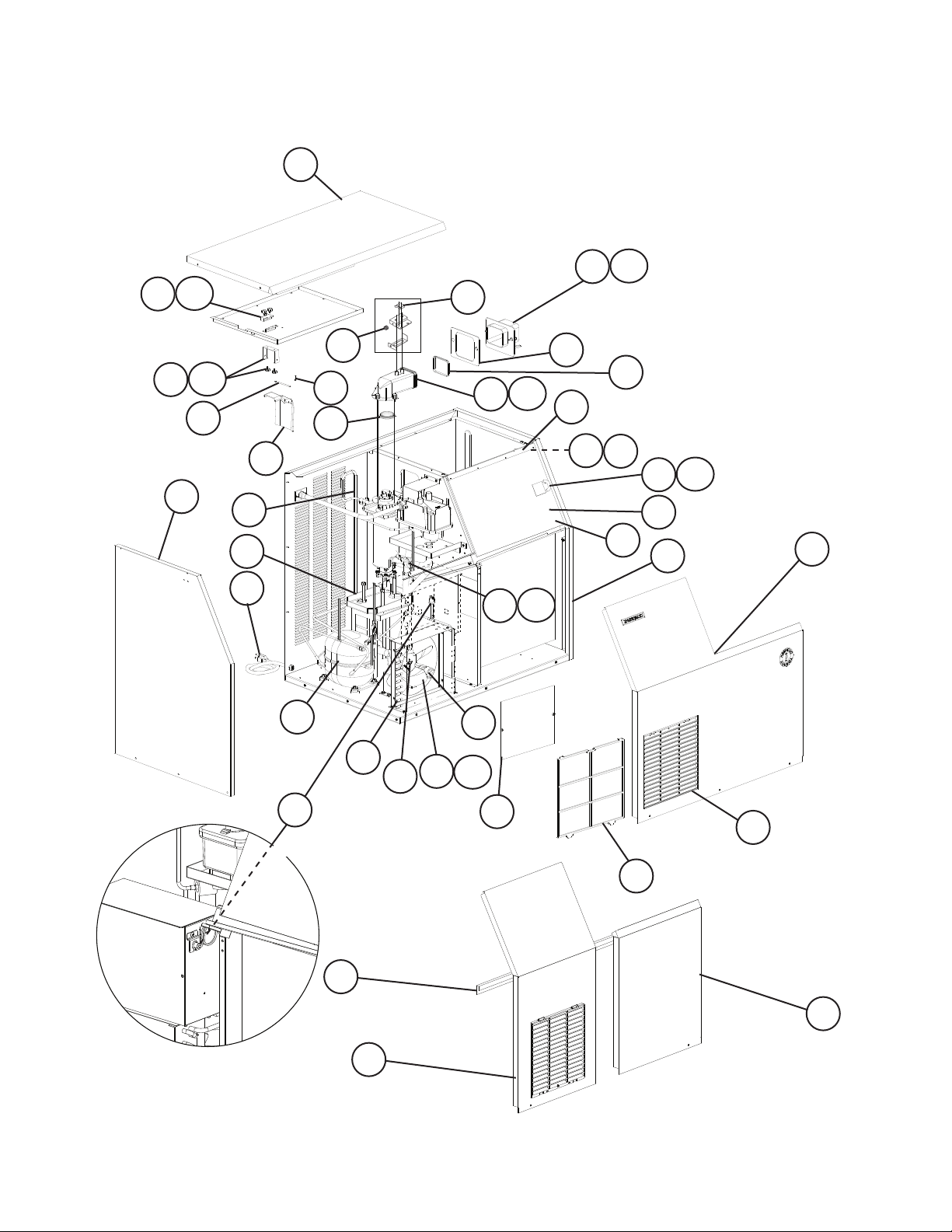
A. Main Assembly
F-300BAF
H-0 to F-0
18a
18
1
12a
12
M-1 to A-0
19
15
2
15a
16
35
21
38
14
29
A-1 and Later
17
9
20
30
31
32
37
32a
10
33
10a
34
13
22
26
11
27
24
28
25
6
28a
3
V-2 and Later
36
A-0 and Earlier
S-0 and Earlier
4
5
23
7
8
V-1 and Earlier
3
V-1 and Earlier
4
Page 5

Title: A. Main Assembly Model: F-300BAF
Required Number
J-0
K-2
M-1
Index
No. Description
1 Top Panel 341383G01 1 1 1 1 -
2 Left Side Panel 341385A01 1 1 -
3 Right Front Panel 341371G01 1 1 -
Front Panel 2A3875-01 1 1
4 Front Panel Bracket 341372-011 1 1 1 1 5 Left Front Panel 341384G01 1 1 -
6 Right Side Panel 341386A02 1 1 1 1 -
7 Louver 103121-03 1 1 1 1 1 1 1 1
8 Air Filter 208283G03 1 1 1 1 1 1 1 1
9 Packing 427151-01 1 1 1 1 1 1 1 1
10 Spout 227129-01 1 1 1 -
10a Thumbscrew 415949G11 3 3 3 3 3 3 3 3
11 Spout Packing A 453663-01 1 1 1 1 1 1 1 1
12 Spout B 227130-01 1 1 1 -
12a Thumbscrew 415949G11 4 4 4 2 2 2 2 2
13 Spout Packing B 4A2769-01 1 1 1 1 1 1 1 1
14 Actuator 208795G01 1 1 1 1 1 1 1 1
15 Actuator Hinge 317058-01 1 -
15a Thumbscrew 415949G08 2 2 2 2 2 2 2 2
16 Shaft 412337-03 1 1 1 1 1 1 1 1
17 Snap Pin 715S-0004 1 1 1 1 1 1 1 1
18 Proximity Switch (Bin Control) 4A2033-01 1 1 1 1 1 1 1 1
18a Thumbscrew 415949G08 2 2 2 2 2 2 2 2
19 Microswitch
(Safety Switch)
20 Spring 459287-01 1 1 1 1 21 Drain Pan 323765G01 1 1 1 1 1 1 1 1
22 Edging 425931-04 1 1 1 1 1 1 1 1
23 Control Box Cover 454838-01 1 1 1 1 1 1 1 1
24 Sliding Door Assembly
(includes items 25 through 28a)
25 Sliding Door 454860-01 1 1 1 1 1 1 1 1
26 Sliding Plate 454861-01 1 1 1 1 1 1 1 1
27 Sliding Collar 454862-01 1 1 1 1 1 1 1 1
28 Knob 444301-02 1 1 1 1 1 1
28a Hex Head Bolt 4×12, SS 7B02-0412 2 2 2 2 2 2 2 2
Material or
Model Number Part Number
Main Assembly
3A4053G01 1 1 1 1
341385A01 1 1 2A3874-01 1 1 1 1
3A1441A01 1 1 1 1 -
3a1442G01 1 1 1 1 -
2A3867-01 1 1 1 1
232636G01 1 1 1 1 1
232654-01 1 232654-03 1 1 1 1
3A0762-01 1 1 1 1 1 1 1
4A2832-01 1 1 1 1 -
341381A01 1 1 1 1 1 1 1 1
H-0
to
K-1
to
M-0
to
S-0
S-1
T- 0
T-1
to
V-1
V-2
A-0
1 1
A-1
to
F-0
5
Page 6

Title: A. Main Assembly Model: F-300BAF
Required Number
J-0
K-2
M-1
Index
No. Description
29 Compressor 4A1177-01 1 -
30 Condenser 228236-01 1 1 1 1 1 1 1 1
31 Fan Motor 4A0815-01 1 1 1 1 1 1 1 1
32 Fan Blade 3A0608-01 1 1 1 1 1 1 1 1
32a Hex Nut 4A1345-01 1 1 1 1 1 1 1 1
33 Thermostatic Expansion Valve 4A1117-01 1 1 1 1 1 1 1 1
34 Thermostatic Expansion Valve
Cover
35 Heat Exchanger 228835G01 1 -
36 High-Pressure Switch 433441-05 1 1 1 1 1 1 1 -
37 Drier 4A1113-01 1 1 1 1 1 1 1 1
38 Power Suppy Cord 4A1773-01 1 1 1 1 1 1 1 1
Material or
Model Number Part Number
Refrigeration Circuit
4A2272-01 1 1 4A4614-01 1 1 1 1 1
4A1168-01 1 1 1 1 1 1 1 1
2A1936G01 1 1 2A4961G01 1 1 1 1 1
463180-05 1
H-0
to
K-1
to
M-0
to
S-0
S-1
T- 0
T-1
to
V-1
V-2
A-0
A-1
to
F-0
6
Page 7

B. Icemaking Unit
F-300BAF
H-0 to F-0
9a
10
9
8
9b
1 1a
7
7b
7a
6
5
4
3
2
2a
7
Page 8

Title: B. Icemaking Unit Model: F-300BAF
Required Number
U-1
H-0
L-0
Q-0
S-1
Index
No. Description
1 Gear Motor SA0103 1 1 1 - For auxiliary codes
1a Hex Head Bolt 8x30, SS 7B02-0830 3 3 3 3 -
Socket Head Cap Screw 8x95, SS 7S12-0895 3 3 3 3
2 Housing 206013G03 1 1 1 1 1 1 1 1
2a Hex Bolt 6×20, SS 7B02-0620 4 -
3 Spline Coupling 418316-01 1 1 1 1 1 1 1 1
4 O-Ring 7616-G040 1 1 1 1 1 -
5 Mechanical Seal 432491-01 1 1 1 1 1 1 1 1
6 Ring 432494-01 1 1 1 1 1 1 1 1
7 Evaporator 341456G01 1
7a Socket Head Cap Screw 6×10, SS 7S12-0610 4 4 4 4 4 4 4 4
7b Split Lock Washer M6, SS 7L22-0600 4 4 4 4 4 4 4 4
8 Auger 341446G01 1 -
9 Extruding Head 340077G01 1 1 1 1 1 1 1 1
9a Seal Bolt P01768-01 3 3 3 3 3 3 3 3
9b Washer 453791-01 3 3 3 3 3 3 3 3
10 Cutter 453790-01 1 1 1 1 1 1 1 1
Material or
Model Number Part Number
2U0147-01 1 1 1 1 4A5439-01 1
458660-01 4 4 4 4A1989-01 4 4 4 4
4A4755-01 1 1 1
2A1722G01 1 2A3308G01 1 1 1 1 1 1
361013G01 1 1 1 1 1 1 1
to
K-2
to
P-1
to
S-0
to
U-0
(J)
V-2
U-1
to
to
(B-H)
V-1
C-0
K-1 and earlier, you
must also order Fuse
Holder 4A0892-02,
Fuse 4A0893-04, and
Fuse Holder Adapter
4A1880-01. For details,
see Hoshizaki Service
Bulletin SB08-0006.
C-1
to
F-0
8
Page 9

C. Water Circuit
F-300BAF
H-0 to F-0
6
2
1
10
5
3
8
4
12
9
7
20
13
11
14
V-1 and Earlier
19
21
11
25
9
V-2 and Later
16
17
18
15
20
13
Page 10

Title: C. Water Circuit Model: F-300BAF
Required Number
M-0
S-1
K-0
to
(J)
V-2
B-1
Index
No. Description
1 Inlet Water Valve 4A0865-01 1 1 1 1 1 1 -
2 Water Supply Pipe 341367G01 1 1 1 1 1 1 -
3 Washer 4A0867-01 1 1 1 1 1 1 1 1
4 Reservoir 2A0753-01 1 1 1 1 1 1 1 1
5 Reservoir Cover 214810-01 1 1 1 1 1 1 1 1
6 Float Switch 435490-01 1 1 1 1 1 1 1 1
7 Drain Valve 4A0866-01 1 1 -
8 Reservoir Separator 4A1255-01 1 1 1 1 1 1 1 1
9 Reservoir Hose 4A1165-05 1 1 1 1 -
10 Reservoir Inlet 4A0869-01 1 1 1 1 1 1 1 1
11 Vinyl Hose L=165 mm 7725-1923 1 1 1 -
12 Vinyl Hose L=360 mm 7725-1923 1 1 1 1 1 -
13 Vinyl Hose L=100 mm 7716-2025 1 1 1 1 1
14 Vinyl Hose L=300 mm 7725-1923 1 1 1 1 1 -
15 Vinyl Hose L=45 mm 7725-1923 1 1 1 -
16 Sillicone Hose L=150 mm 7730I3896 1 1 1 1 1 1 1 1
17 Vinyl Hose L=360 mm 7725-0912 1 1 -
Silicone Hose 7730I3896 1 1 1 -
18 Drain Fitting 4A0776G01 2 2 2 2 2 2 2 -
19 Drain Pan 341376G01 1 1 1 1 1 -
20 Elbow 4A1017-01 2 2 2 2 2 1 1 1
21 Vinyl Hose L=70 mm 7725-1923 1 1 1 1 1 -
Hose Clamp 16 mm 435934-06 1 Clamp 12-13.5 mm 421642-04 2 Clamp 22-25 mm 421642-09 4 Hose Clamp 17 mm 435934-05 1 Hose Clamp 26.2 mm 4A2017-01 6 6 7 7 6 6 6
Hose Clamp 30.2 mm 4A2017-02 4 4 3 3 2 2 2
Hose Clamp 13.5 mm 4A2017-04 3 Hose Clamp 15.1 mm 4A2017-08 3 3 3 4 4 4
Hose Clamp 20.6 mm 4A2017-05 1 1 1 1 1 1 1
Hose Clamp 22.2 mm 4A2017-06 1 1 1 1 1 1 1
Material or
Model Number Part Number
4A5309-01 1 1
341367G02 1 1
4A5309-01 1 - 4A2772-01 1 1 1 1 1
4A1165-09 1 1 1 1
7716-2025 1 1 -
L=385 mm 1 1 1
L=345 mm 1 1 1
L=285 mm 1 1 1
L=50 mm 7716-1025 1 1 1 1 1
L=300 mm 1 1 1
4A5527-01 2
323765G01 1 1 1
Hose Clamps
H-0
J-0 J-1
to
L-1
S-0
(H)
to
V-1
to
B-0
to
C-0
C-1
to
F-0
10
Page 11

D. Control Box Assembly
F-300BAF
1/2
H-0 to L-0
5
11 12
2a
2
6
7
9
13 14
K-2 to L-0
H-0 to K-1
4
D. Control Box Assembly
F-300BAF
2/2
L-1 to F-0
5
10
8
1
3
2a
2
9
6
9
M-1 to A-0
8
13 14
4
12
11
L-1 to S-0
S-1 and Later
10
1
3
11
Page 12

Title: D. Control Box Assembly Model: F-300BAF
Required Number
Index
No. Description
Material or
Model Number Part Number
H-0
to
K-1
K-2
L-0
L-1
M-0
M-1
to
S-0
S-1
to
A-0
A-1
to
C-0 C-1
1 Start Capacitor 3A0076-01
2 Control Board (timer board) 437305-01 1 1 1 1 1 1 1 -
4A5591-01 1
2a Control Board Support 4A0336-03
3 Gear Motor Capacitor 12MFD,
4A0894-01 1 1 1 1 -
330VAC
10MFD,
416921-05 1 1 -
280VAC
10MFD,
443192-01 1 1
250VAC
4 Gear Motor External Protector 440972-02 1 -
427253-01 1 1 1 1
5 Rocker Switch (Control and
4A0558-01 2 2 2 2 2 2 2 2
Power Switch)
6 Gear Motor Protect Relay 406132-07 1 1 1 1 1 1 1 1
7 Circuit Protect Relay 418271-05 1 1 8 Drain Relay (Flush Relay) 430173-03 1 1 1 1 1 1 1 1
9 Water Control Relay and Safety
406132-06 1 1 1 2 2 1 1 1
Relay
10 Control Transformer 4A0557-01 1 1 1 1 1 1 1 1
11 Fuse Holder 4A0892-01 1 1 1 1 1 -
4A3449-01 1 4A5443-01 1 1
12 Control Board Fuse
AGC-1A,
250VAC
4A0893-01 1 1 1 1 1 1 1 1
13 Fuse Holder 4A0892-02 1 1 1 14 Gear Motor Fuse
GMD1.5A,
250VAC
4A0893-04 1 1 1 -
C-2
to
F-0
12
Page 13

E. Accessories & Labels
F-300BAF
H-0 to F-0
2
1
4
Title: E. Accessories & Labels Model: F-300BAF
H-0
K-0
Index
No. Description
1 Penguin Label 4A0526-01 1 1 1
2 Hoshizaki Emblem 4A0560-01 1 1 1
3 Scoop 437625-01 1 -
4 Adjustable Leg 434043-01 4 4 -
Material or
Model Number Part Number
4A2246-01 1 1
4A2525-01 4
to
J-1
to
Q-0
13
Required Number
Q-1
to
F-0
 Loading...