

Instruction Manual
Modular Flaker
Models
F-450MAJ(-C)
F-801MAJ(-C), MWJ(-C)
F-1002MAJ(-C), MWJ(-C), MRJ(-C), MLJ
F-1501MAJ(-C), MWJ(-C), MRJ(-C)
F-2001MWJ, MRJ/3(-C), MLJ
FD-650MAJ-C, MWJ-C, MRJ-C
FD-1002MAJ-C, MRJ-C
hoshizakiamerica.com
Issued: 7-27-2017
Revised: 5-30-2018

WARNING
Only qualied service technicians should install and service the appliance. To
obtain the name and phone number of your local Hoshizaki Certied Service
Representative, visit www.hoshizaki.com. No installation or service should be
undertaken until the technician has thoroughly read this Instruction Manual.
Likewise, the owner/manager should not proceed to operate the appliance until the
installer has instructed them on its proper operation. Failure to install, operate, and
maintain the appliance in accordance with this manual will adversely affect safety,
performance, component life, and warranty coverage and may result in costly water
damage. Proper installation is the responsibility of the installer. Product failure or
property damage due to improper installation is not covered under warranty.
Hoshizaki provides this manual primarily to assist qualied service technicians in the
installation, maintenance, and service of the appliance.
Should the reader have any questions or concerns which have not been satisfactorily
addressed, please call, send an e-mail message, or write to the Hoshizaki Technical
Support Department for assistance.
Phone: 1-800-233-1940; (770) 487-2331
Fax: 1-800-843-1056; (770) 487-3360
E-mail: techsupport@hoshizaki.com
618 Highway 74 South
Peachtree City, GA 30269
Attn: Hoshizaki Technical Support Department
NOTE: To expedite assistance, all correspondence/communication MUST include the
following information:
• Model Number
• Serial Number
• Complete and detailed explanation of the problem.
2

IMPORTANT
This manual should be read carefully before the appliance is installed and operated.
Read the warnings and guidelines contained in this manual carefully as they
provide essential information for the continued safe use and maintenance of the
appliance. Retain this manual for any further reference that may be necessary.
CONTENTS
Important Safety Information ................................................................................................. 5
I. Specications ...................................................................................................................... 7
A. Electrical and Refrigerant Data ..................................................................................... 7
1. F-450MAJ(-C) .......................................................................................................... 7
2. F-801M_J(-C) ........................................................................................................... 7
3. F-1002M_J(-C)......................................................................................................... 8
4. F-1501M_J(-C) ......................................................................................................... 8
5. F-2001M_J(-C) ......................................................................................................... 9
6. F-2001MRJ3 ............................................................................................................ 9
7. FD-650M_J-C ......................................................................................................... 10
8. FD-1002M_J(-C) .................................................................................................... 10
B. Dimensions/Connections .............................................................................................11
1. Air-Cooled Models (MAJ(-C)) ..................................................................................11
2. Water-Cooled Models (MWJ(-C)) ........................................................................... 12
3. Remote Models (MRJ/3(-C)) .................................................................................. 13
4. Low Side, Parallel Rack System Models (MLJ) ..................................................... 14
5. Remote Condenser Unit URC-5F
(use with F-1002MRJ(-C), FD-650MRJ-C, FD-1002MRJ-C) .................................. 15
6. Remote Condenser Unit URC-14F
(use with F-1501MRJ(-C)) ...................................................................................... 15
7. Remote Condenser Unit URC-22F
(use with F-2001MRJ/3(-C)) .................................................................................. 16
II. Installation and Operating Instructions ............................................................................ 17
A. Location ...................................................................................................................... 17
B. Checks Before Installation ........................................................................................... 17
C. How to Remove Panels ............................................................................................... 18
D. Dispenser Unit/Ice Storage Bin and Icemaker Setup .................................................. 19
E. Electrical Connection .................................................................................................. 20
F. Water Supply and Drain Connections .......................................................................... 22
1. Icemaker ................................................................................................................ 23
2. Water-Cooled Condenser....................................................................................... 24
G. Remote Condenser Unit Installation ........................................................................... 26
1. Location ................................................................................................................. 26
2. Checks Before Installation ..................................................................................... 27
3. Setup ..................................................................................................................... 27
4. Line Set Size and Refrigerant Charge ................................................................... 28
5. Line Set Installation ............................................................................................... 29
6. Electrical Connection ............................................................................................. 32
7. Stacking Remote Condenser Unit .......................................................................... 33
3

H. Parallel Rack System Connection ............................................................................... 34
1. Line Set Size and Rack System Requirements ...................................................... 34
2. Line Set Installation ............................................................................................... 34
I. Final Checklist .............................................................................................................. 37
J. Startup ......................................................................................................................... 38
K. Bin Control Check ....................................................................................................... 39
1. Infrared Sensor Check ........................................................................................... 39
2. Infrared Sensor Shutdown Delay ........................................................................... 41
L. Alarm Safeties ............................................................................................................. 42
III. Maintenance ................................................................................................................... 43
A. Maintenance Schedule ................................................................................................ 44
B. Cleaning and Sanitizing Instructions ........................................................................... 45
IV. Preparing the Appliance for Periods of Non-Use ............................................................ 49
V. Disposal ........................................................................................................................... 51
4
Important Safety Information
Throughout this manual, notices appear to bring your attention to situations which could
result in death, serious injury, damage to the appliance, or damage to property.
WARNING Indicates a hazardous situation which could result in death or
serious injury.
NOTICE Indicates a situation which could result in damage to the
appliance or property.
IMPORTANT Indicates important information about the installation, use, and
care of the appliance.
WARNING
The appliance should be destined only to the use for which it has been expressly
conceived. Any other use should be considered improper and therefore dangerous.
The manufacturer cannot be held responsible for injury or damage resulting
from improper, incorrect, and unreasonable use. Failure to install, operate, and
maintain the appliance in accordance with this manual will adversely affect safety,
performance, component life, and warranty coverage and may result in costly water
damage.
To reduce the risk of death, electric shock, serious injury, or re, follow basic
precautions including the following:
• Only qualied service technicians should install and service the appliance.
• The appliance must be installed in accordance with applicable national, state, and
local codes and regulations.
• Electrical connection must be hard-wired and must meet national, state, and local
electrical code requirements. Failure to meet these code requirements could result
in death, electric shock, serious injury, re, or damage.
• The icemaker requires an independent power supply of proper capacity. See the
nameplate for electrical specications. Failure to use an independent power supply
of proper capacity can result in a tripped breaker, blown fuse, damage to existing
wiring, or component failure. This could lead to heat generation or re.
• THE ICEMAKER MUST BE GROUNDED. Failure to properly ground the icemaker
could result in death or serious injury.
• To reduce the risk of electric shock, do not touch the power switch or control switch
with damp hands.
• Move the power switch to the "OFF" position and turn off the power supply before
servicing. Lockout/Tagout to prevent the power supply from being turned back on
inadvertently.
• Do not place ngers or any other objects into the ice discharge opening.
• Do not make any alterations to the appliance. Alterations could result in electric
shock, injury, re, or damage.
5

WARNING, continued
• The appliance is not intended for use by persons (including children) with reduced
physical, sensory, or mental capabilities, or lack of experience and knowledge,
unless they have been given supervision or instruction concerning use of the
appliance by a person responsible for their safety.
• Children should be properly supervised around the appliance.
• Do not climb, stand, or hang on the appliance or allow children or animals to do so.
Serious injury could occur or the appliance could be damaged.
• Do not use combustible spray or place volatile or ammable substances near the
appliance. They might catch re.
• Keep the area around the appliance clean. Dirt, dust, or insects in the appliance
could cause harm to individuals or damage to the appliance.
Additional Warning for Remote Models
• THE REMOTE CONDENSER UNIT MUST BE GROUNDED. The power supply and
ground connection to the remote condenser unit are supplied from the icemaker.
Failure to properly ground the remote condenser unit could result in death or
serious injury.
• Wire routing (conduit) and disconnect (if required) must meet national, state, and
local electrical code requirements. Failure to meet these code requirements could
result in death, electric shock, serious injury, re, or damage.
NOTICE
• Follow the water supply, drain connection, and maintenance instructions carefully to
reduce the risk of costly water damage.
• In areas where water damage is a concern, install in a contained area with a oor
drain.
• Install the icemaker in a location that stays above freezing. Normal operating
ambient temperature must be within 45°F to 100°F (7°C to 38°C).
• Do not leave the icemaker on during extended periods of non-use, extended
absences, or in sub-freezing temperatures. To properly prepare the icemaker for
these occasions, follow the instructions in "IV. Preparing the Icemaker for Periods of
Non-Use."
• Do not place objects on top of the appliance.
• The dispenser unit/ice storage bin is for ice use only. Do not store anything else in
the dispenser unit/ice storage bin.
6

I. Specications
A. Electrical and Refrigerant Data
The rating label and nameplate provide electrical and refrigerant data. The rating label
can be seen by removing the front panel. The nameplate is located on the rear panel. For
certication marks, see the nameplate.
We reserve the right to make changes in specications and design without prior notice.
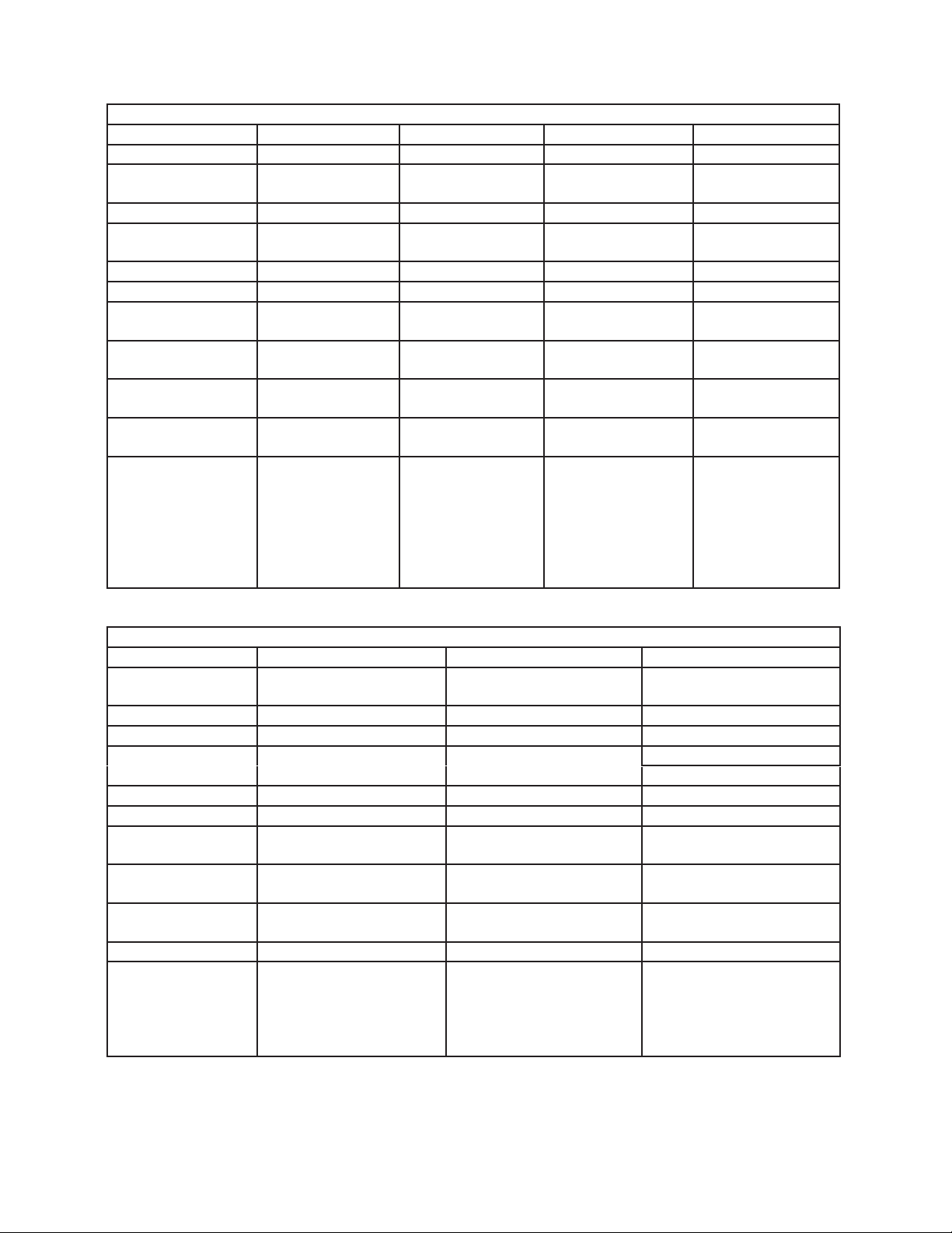
1. F-450MAJ(-C)
Single Phase
Model Number F-450MAJ(-C)
AC Supply Voltage 115/60/1
Compressor 115V 8.4RLA 50LRA
Gear Motor 115V 2.4FLA 1/4HP
Fan Motor 115V 1FLA 50W
Other 115V 0.03A
Maximum Fuse Size 15 AMPS
Max. HACR Breaker
(USA Only)
Max. Circuit Breaker
(Canada Only)
Minimum Circuit
Ampacity
Design Pressure HI-427PSI LO-230PSI
Refrigerant 404A 15.2 OZ.
15 AMPS
15 AMPS
15 AMPS
2. F-801M_J(-C)
Single Phase
Model Number F-801MAJ(-C) F-801MWJ(-C)
AC Supply Voltage 115/60/1 115/60/1
Compressor 115V 7.5RLA 54.5LRA 115V 7.5RLA 54.5LRA
Gear Motor 115V 3.0FLA 200W 115V 3.0FLA 200W
Fan Motor 115V 1.0FLA 1/15HP – – –
Other 115V 0.03A 115V 0.03A
Maximum Fuse Size 15 AMPS 15 AMPS
Max. HACR Breaker
(USA Only)
Max. Circuit Breaker
(Canada Only)
Minimum Circuit
Ampacity
Design Pressure HI - 467PSI LO - 250PSI HI - 467PSI LO - 250PSI
Refrigerant 404A 1 LB. 12 OZ. 404A 10.7 OZ.
15 AMPS 15 AMPS
15 AMPS 15 AMPS
15 AMPS 15 AMPS
7
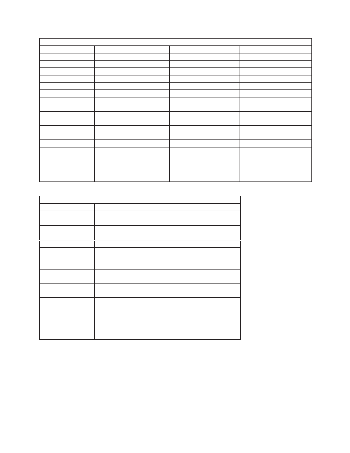
3. F-1002M_J(-C)
Single Phase
Model Number F-1002MAJ(-C) F-1002MWJ(-C) F-1002MRJ(-C) F-1002MLJ(-C)
AC Supply Voltage 115/60/1 115/60/1 115/60/1 115/60/1
Compressor 115V 11.2RLA
93LRA
Gear Motor 115V 3.0FLA 200W 115V 3.0FLA 200W 115V 3.0FLA 200W 115V 3.0FLA 200W
Fan Motor 115V 1.0FLA
1/15HP
Other 115V 0.03A 115V 0.03A 115V 0.53A 115V 0.53A
Maximum Fuse Size 20 AMPS 20 AMPS 20 AMPS 15 AMPS
Max. HACR Breaker
(USA Only)
Max. Circuit Breaker
(Canada Only)
Minimum Circuit
Ampacity
Design Pressure HI-467PSI
Refrigerant 404A 2 LB. 4 OZ. 404A 12.3 OZ. 404A
20 AMPS 20 AMPS 20 AMPS 15 AMPS
20 AMPS 20 AMPS 20 AMPS 15 AMPS
20 AMPS 20 AMPS 20 AMPS 15 AMPS
LO-250PSI
115V 10.7RLA
93LRA
– – – 115V 3A MAX
HI-427PSI
LO-250PSI
115V 11.2RLA
93LRA
(Fan in URC)
HI-467PSI
LO-250PSI
Total Refrigerant
Charge with
Hoshizaki Remote
Condenser Unit
URC-5F: 4LB. 1.2
OZ.
– – –
– – –
HI-467PSI
LO-250PSI
Use only with 404A,
407A, or 407F
4. F-1501M_J(-C)
Single Phase
Model Number F-1501MAJ(-C) F-1501MWJ(-C) F-1501MRJ(-C)
AC Supply Voltage 208-230/60/1 (3 wire with
neutral)
Compressor 208-230V 9.3RLA 56LRA 208-230V 9.3RLA 56LRA 208-230V 9.3RLA 56LRA
Gear Motor 115V 5.6FLA 400W 115V 5.6FLA 400W 115V 5.6FLA 400W
Fan Motor 115V 1.0FLA 1/15HP Cabinet: 115V 0.51FLA 8W Cabinet: 115V 0.51FLA 8W
Other 115V 0.03A 115V 0.03A 115V 0.03A
Maximum Fuse Size 20 AMPS 20 AMPS 20 AMPS
Max. HACR Breaker
(USA Only)
Max. Circuit Breaker
(Canada Only)
Minimum Circuit
Ampacity
Design Pressure HI-467PSI LO-250PSI HI-427PSI LO-250PSI HI-467PSI LO-250PSI
Refrigerant 404A 2 LB. 5 OZ. 404A 1 LB 4.5 OZ. 404A
20 AMPS 20 AMPS 20 AMPS
20 AMPS 20 AMPS 20 AMPS
20 AMPS 20 AMPS 20 AMPS
208-230/60/1 (3 wire with
neutral)
208-230/60/1 (3 wire with
neutral)
Remote: 115V 3A MAX
Total Refrigerant Charge
with Hoshizaki Remote
Condenser Unit URC-14F:
9LB. 9 OZ.
8

5. F-2001M_J(-C)
Single Phase
Model Number F-2001MWJ(-C) F-2001MRJ(-C) F-2001MLJ
AC Supply Voltage 208-230/60/1 208-230/60/1 115/60/1
Compressor 240V 10.8RLA 96LRA 240V 10.8RLA 96LRA – – –
Gear Motor 120V 5.6 FLA 400W 120V 5.6 FLA 400W 120V 5.6 FLA 400W
Cabinet Fan Motor 115V 0.51 FLA 8W 115V 0.51 FLA 8W 115 0.51 FLA 8W
Remote Fan Motor – – – 120V 3A MAX
Other 120V 0.03A 120V 0.03A 120V 0.3A
Maximum Fuse Size 30 AMPS 30 AMPS 15 AMPS
Max. HACR Breaker
(USA Only)
Max. Circuit Breaker
(Canada Only)
Minimum Circuit
Ampacity
Design Pressure HI-467PSI
Refrigerant 404A 2 LB. 404A
30 AMPS 30 AMPS 15 AMPS
30 AMPS 30 AMPS 15 AMPS
30 AMPS 30 AMPS 15 AMPS
LO-290PSI
HI-467PSI
LO-290PSI
Total Refrigerant Charge
with Hoshizaki Remote
Condenser Unit
URC-22F: 15LB. 14 OZ.
HI-467PSI
LO-290PSI
Use only with 404A,
407A, or 407F
6. F-2001MRJ3
Three Phase
Model Number F-2001MRJ3
AC Supply Voltage 208-230/60/3
Compressor 240V 9.0RLA 75LRA
Gear Motor 120V 5.6 FLA 400W
Cabinet Fan Motor 115V 0.51 FLA 8W
Remote Fan Motor 120V 3A MAX
Other 120V 0.03A
Maximum Fuse Size 20 AMPS
Max. HACR Breaker
(USA Only)
Max. Circuit Breaker
(Canada Only)
Minimum Circuit
Ampacity
Design Pressure HI-467PSI
Refrigerant 404A
20 AMPS
20 AMPS
20 AMPS
LO-290PSI
Total Refrigerant Charge
with Hoshizaki Remote
Condenser Unit
URC-22F: 15LB. 14 OZ.
9
7. FD-650M_J-C
Single Phase
Model Number FD-650MAJ-C FD-650MWJ-C FD-650MRJ-C
AC Supply Voltage 115/60/1 115/60/1 115/60/1
Compressor 115V 7.9RLA 54.5LRA 115V 5.5RLA 50LRA 115V 5.5RLA 50LRA
Gear Motor 120V 2.3FLA 1/4HP 120V 2.3FLA 1/4HP 120V 2.3FLA 1/4HP
Fan Motor 115V 1.0FLA 1/15HP (each) - 120V 3A MAX (Fan in URC)
Other 115-120V 0.3A 115-120V 0.3A 115-120V 0.3A
Maximum Fuse Size 20 AMPS 20 AMPS 20 AMPS
Max. HACR Breaker
(USA Only)
Max. Circuit Breaker
(Canada Only)
Minimum Circuit
Ampacity
Design Pressure HI-427PSI LO-230PSI HI-427PSI LO-230PSI HI-427PSI LO-230PSI
Refrigerant 404A 12.4 OZ. 404A 15.0 OZ. 404A
20 AMPS 20 AMPS 20 AMPS
20 AMPS 20 AMPS 20 AMPS
20 AMPS 20 AMPS 20 AMPS
Total Refrigerant Charge
with Hoshizaki Remote
Condenser Unit URC-5F:
4LB. 1.2 OZ.
8. FD-1002M_J(-C)
Single Phase
Model Number FD-1002MAJ-C FD-1002MRJ-C
AC Supply Voltage 115/60/1 115/60/1
Compressor 115V 11.2RLA 93LRA 115V 11.2RLA 93LRA
Gear Motor 115V 3.0FLA 200W 115V 3.0FLA 200W
Fan Motor 115V 1.0FLA 1/15HP 115V 3A MAX (Fan in URC)
Other 115V 0.03A 115V 0.53A
Maximum Fuse Size 20 AMPS 20 AMPS
Max. HACR Breaker
(USA Only)
Max. Circuit Breaker
(Canada Only)
Minimum Circuit
Ampacity
Design Pressure HI - 467PSI LO - 250PSI HI - 467PSI LO - 250PSI
Refrigerant 404A 2 LB. 4.1 OZ. 404A
20 AMPS 20 AMPS
20 AMPS 20 AMPS
20 AMPS 20 AMPS
Total Refrigerant Charge
with Hoshizaki Remote
Condenser Unit URC-5F:
4LB. 1.2 OZ.
10

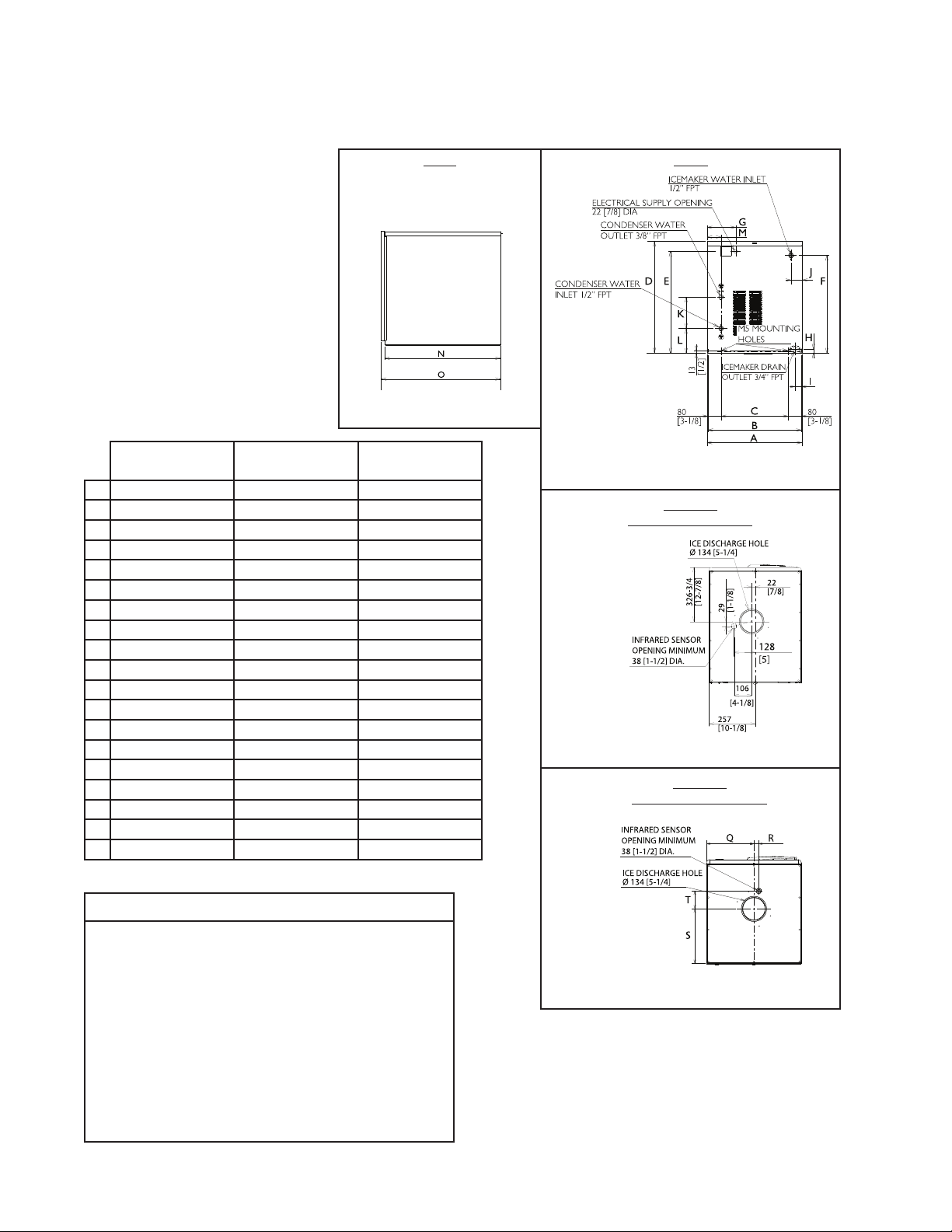
B. Dimensions/Connections
G
1. Air-Cooled Models (MAJ(-C))
Side
Model Shown: F-801MAJ
F-450MAJ(-C) F-801MAJ(-C)
F-1002MAJ(-C)
A 560 [22] 560 [22] 768 [30-1/4] 560 [22]
B 556 [21-7/8] 556 [21-7/8] 756 [29-3/4] 556 [21-7/8]
C 395 [15-9/16] 395 [15-9/16] 602 [23-3/4] 395 [15-9/16]
D 558 [21-15/16] 659 [25-15/16] 874 [34-3/8] 659 [25-15/16]
E 499 [19-11/16] 599 [23-9/16] 817 [32-1/8] 599 [23-9/16]
F 476 [18-11/16] 575 [22-5/8] 731 [28-13/16] 575 [22-5/8]
G 169 [6-11/16] 169 [6-5/8] 165 [6-1/2] 169 [6-5/8]
H 22 [7/8] 24 [15/16] 25 [1] 24 [15/16]
I 42 [1-5/8] 35 [1-3/8] 44 [1-3/4] 37 [1-1/2]
J 64 [2-1/2] 67 [2-5/8] 87 [3-7/16] 64 [2-1/2]
K 672 [26-7/16] 675 [26-9/16] 676 [26-5/8] 587 [23-182]
L 695 [27-3/8] 692 [27-1/4] 699 [27-1/2] 607 [24]
M 260 [10-3/16] ------- 323 [12-11/16] 280 [11]
N 28 [1-1/8] ------- 30 [1-3/16] 28 [1-1/8]
O 370 [14-1/2] ------- 330 [13] 324 [12-11/16]
P 104 [4-1/8] ------- 113 [4-1/2] 106 [4-3/16]
F-1501MAJ(-C)
F-2001MAJ(-C)
FD-650MAJ-C
FD-1002MAJ-C
Units: mm [in.]
Rear
Model Shown: F-801MAJ
Bottom
F-801 and F-1002
Model Shown: F-801MAJ
Bottom
F-450, F-1501,
FD-650, and FD-1002
NOTICE
• Allow 6" (15 cm) clearance at rear
and sides for proper air circulation
and ease of maintenance and/or
service should they be required. Allow
24"(61cm) clearance at top to allow
for removal of the auger.
• The dispenser unit/ice storage bin
opening must accommodate the
bottom opening as in the illustration.
Model Shown: FD-650MAJ-C
11
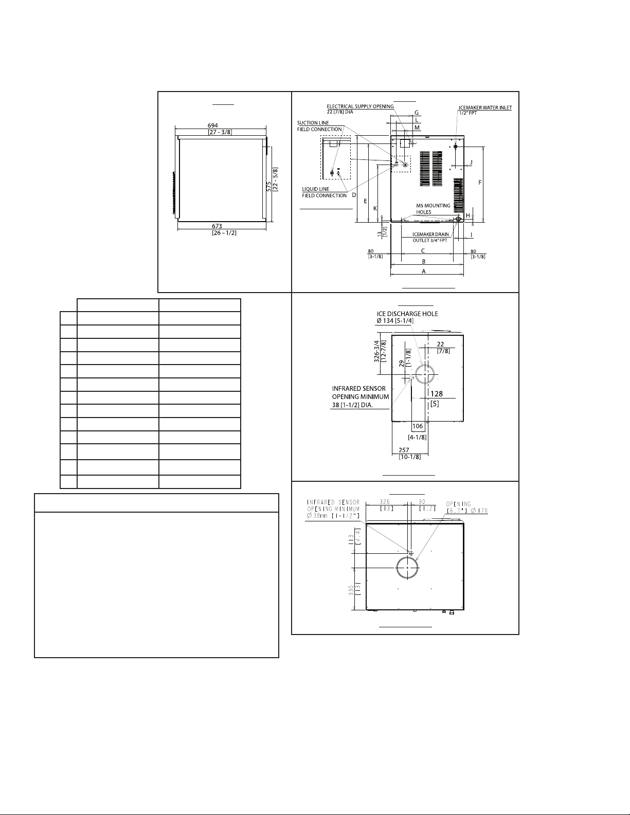
2. Water-Cooled Models (MWJ(-C))
G
Units: mm [in.]
Side
Model Shown: F-801MWJ
F-801MWJ(-C)
F-1002MWJ(-C)
A 560 [22] 768 [30-1/4] 560 [22]
B 550 [21-5/8] 756 [29-3/4] 550 [21-5/8]
C 395 [15-9/16] 602 [23-3/4] 395 [15-9/16]
D 659 [25-15/16] 874 [34-3/8] 659 [25-15/16]
E 599 [23-9/16] 817 [32-1/8] 599 [23-5/8]
F 575 [22-5/8] 731 [28-13/16] 575 [22-5/8]
G 169 [6-5/8] 165 [6-1/2] 169 [6-5/8]
H 24 [15/16] 25 [1] 23 [7/8]
I 41 [1-5/8] 44 [1-3/4] 43 [1-3/4]
J 67 [2-5/8] 87 [3-7/16] 62 [2-1/2]
K 185 [7-5/16] 371 [14-5/8] 235 [9-1/4]
L 145 [5-11/16] 139 [5-1/2] 95 [3-3/4]
M 80 [3-1/8] 127 [5] 83 [3-1/4]
N 675 [26-9/16] 676 [26-5/8] 587 [23-1/8]
O 695 [27-3/8] 699 [27-1/2] 607 [24]
Q ------- 323 [12-11/16] 280 [11]
R ------- 30 [1-3/16] 28 [1-1/8]
S ------- 330 [13] 324 [12-11/16]
T ------- 113 [4-1/2] 106 [4-3/16]
F-1501MWJ(-C)
F-2001MWJ(-C)
FD-650MWJ-C
Rear
Model Shown: F-801MWJ
Bottom
F-801 and F-1002
Model Shown: F-801MWJ
Bottom
F-1501 and FD-650
NOTICE
• Allow 6" (15 cm) clearance at rear
and sides for proper air circulation
and ease of maintenance and/or
service should they be required. Allow
24"(61cm) clearance at top to allow
for removal of the auger.
• The dispenser unit/ice storage bin
opening must accommodate the
bottom opening as in the illustration.
Model Shown: FD-650MWJ-C
12

3. Remote Models (MRJ/3(-C))
G
Units: mm [in.]
Side
Model Shown: FD-650MRJ-C
F-1002MRJ(-C) F-1501MRJ(-C) FD-650MRJ-C
FD-1002MRJ-C
F-2001MRJ/3(-C)
A 560 [22] 768 [30-1/4] 560 [22]
B 556 [21-7/8] 756 [29-3/4] 556 [21-7/8]
C 395 [15-9/16] 602 [23-3/4] 395 [15-1/2]
D 659 [25-15/16] 874 [34-3/8] 659 [26]
E 599 [23-9/16] 817 [32-1/8] 599 [23-5/8]
F 575 [22-5/8] 731 [28-13/16] 575 [22-5/8]
G 169 [6-5/8] 165 [6-1/2] 169 [6-5/8]
H 24 [15/16] 25 [1] 23 [7/8]
I 35 [1-3/8] 44 [1-3/4] 43 [1-3/4]
J 65 [2-1/2] 87 [3-7/16] 62 [2-1/2]
K 434 [17-1/16] 524 [20-5/8] 434 [17-1/8]
L 40 [1-9/16] 92 [3-5/8] 70 [2-3/4]
M 100 [3-15/16] 154 [6] 60 [2-3/8]
N 70 [2-3/4] 70 [2-3/4] 70 [2-3/4]
O 673 [26-1/2] 676 [26-5/8] 587 [23-1/8]
P 708 [27-3/4] 699 [27-1/2] 607 [23-13/16]
Q ------- 323 [12-11/16] 280 [11]
R ------- 30 [1-3/16] 28 [1-1/8]
S ------- 330 [13] 324 [12-11/16]
T ------- 113 [4-1/2] 106 [4-3/16]
Rear
Model Shown: FD-650MRJ-C
Bottom
F-1002
Model Shown: FD-650MRJ-C
Bottom
F-1501,
FD-650, and FD-1002
NOTICE
• Allow 6" (15 cm) clearance at rear
and sides for proper air circulation
and ease of maintenance and/or
service should they be required. Allow
24"(61cm) clearance at top to allow
for removal of the auger.
• The dispenser unit/ice storage bin
opening must accommodate the
bottom opening as in the illustration.
Model Shown: FD-650MRJ-C
13
4. Low Side, Parallel Rack System Models (MLJ)
32
[1-1/4]
G
Side
F-2001MLJ
Units: mm [in.]
Rear
F-1002MLJ
F-1002MLJ F-2001MLJ
A 560 [22] 768 [30-1/4]
B 555 [21-7/8] 762 [30]
C 395 [15-9/16] 602 [23-11/16]
D 658 [25-7/8] 874 [34-7/16]
E 598 [23-1/2] 817 [32-3/16]
F 575 [22-5/8] 705 [27-3/4]
G 169 [6-5/8] 165 [6-1/2]
H 24 [15/16] 24 [15/16]
I 35 [1-3/8] 43 [1-11/16]
J 64 [2-1/2] 75 [2-15/16]
K
434 [17-1/16] 524 [20-5/8]
L
40 [1-9/16] 92 [3-5/8]
M 60 [2-3/8] 62 [2-7/16]
NOTICE
• Allow 6" (15 cm) clearance at rear
and sides for proper air circulation
and ease of maintenance and/or
service should they be required. Allow
24"(61cm) clearance at top to allow
for removal of the auger.
Bottom
F-1002MLJ
Bottom
• The dispenser unit/ice storage bin
opening must accommodate the
bottom opening as in the illustration.
F-2001MLJ
14

5. Remote Condenser Unit URC-5F
(use with F-1002MRJ(-C), FD-650MRJ-C, FD-1002MRJ-C)
NOTICE
Allow 24" (61cm) clearance
at front and rear for proper
air circulation and ease of
maintenance and/or service
should they be required.
URC-5F Heat of Rejection
Icemaker
Model
F-1002MRJ 7,660 BTU/hr
F-1002MRJ-C 7,840 BTU/hr
FD-650MRJ-C 4,900 BTU/hr
FD-1002MRJ-C 8,900 BTU/hr
AT 90°F (32°C)
WT 70°F (21°C)
Top
Rear
Units: mm [in.]
6. Remote Condenser Unit URC-14F
(use with F-1501MRJ(-C))
NOTICE
Allow 24" (61cm) clearance
at front and rear for proper
air circulation and ease of
maintenance and/or service
should they be required.
URC-14F Heat of Rejection
Icemaker
Model
F-1501MRJ
F-1501MRJ-C
AT 90°F (32°C)
WT 70°F (21°C)
13,194 BTU/hr
Units: mm [in.]
Top
Rear
15

7. Remote Condenser Unit URC-22F
(use with F-2001MRJ/3(-C))
NOTICE
Allow 24" (61cm) clearance
at front and rear for proper
air circulation and ease of
maintenance and/or service
should they be required.
Units: mm [in.]
Top
Rear
URC-22F Heat of Rejection
AT 90°F (32°C)
Icemaker Model
F-2001MRJ 16,475 BTU/hr
F-2001MRJ-C 17,690 BTU/hr
F-2001MRJ3 16,890 BTU/hr
WT 70°F (21°C)
16
 Loading...