

Page 1
EXTRA
BELT
EXTRA
PAPER
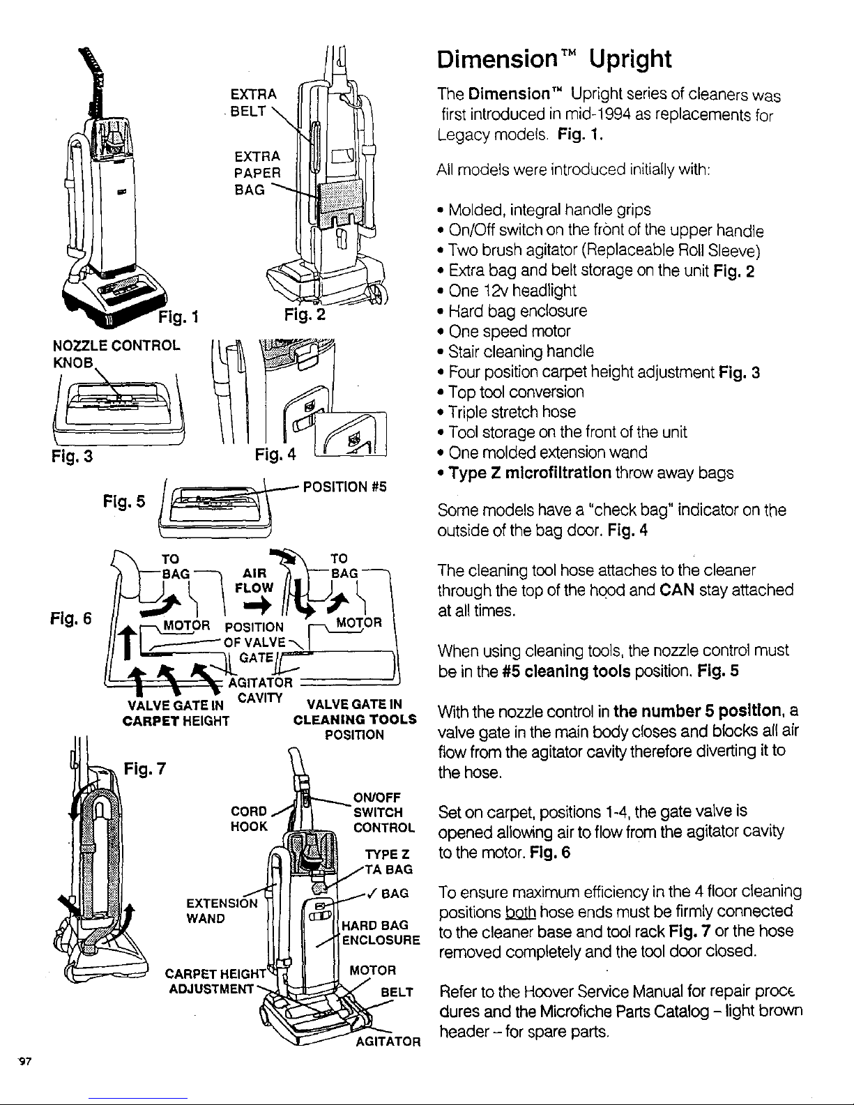
Dimension TM Upright
The Dimension" Upright series of cleaners was
first introduced in mid-1994 as replacements for
Legacy models. Fig. 1.
All models were introduced initially with:
97
1 Fig. 2
Fig, 3
Fig. 6
Fig. 5 l_ POSITION#5
Oo_ ,,.%_;0°_
l ,_ ZOR POSITION R
I _ OFVALVE-_ !
=='_'-_ I GATE/F "--_
•. ,- - AGITATOR
II •
VALVE GATE IN CAVITY VALVE GATEIN
CARPET HEIGHT CLEANING TOOLS
POSITION
Fig. 7
ON/OFF
CORO SW,TCN
_) HOOK CONTROL
TYPE Z
SAG
Libel. 1 ,AG
EXTENSION
WAND
;_ CARPE'f MOTOR
ADJU BELT
AGITATOR
,, Molded, integral handle grips
• On/Off switch on the front of the upper handle
• Two brush agitator (Replaceable Roll Sleeve)
• Extra bag and belt storage on the unit Fig. 2
• One 12v headlight
• Hard bag enclosure
• One speed motor
• Stair cleaning handle
• Four position carpet height adjustment Fig. 3
• Top tool conversion
• Triple stretch hose
• Tool storage on the front of the unit
• One molded extension wand
• Type Z mlcrofiltratlen throw away bags
Some models have a "check bag" indicator on the
outside of the bag door. Fig, 4
The cleaning tool hose attaches to the cleaner
through the top of the hood and CAN stay attached
at all times.
When using cleaning tools, the nozzle control must
be in the #5 cleaning tools position. Fig, 5
Withthe nozzle control inthe number 5 position, a
valve gate in the main body closes and blocks all air
flow from the agitator cavity therefore diverting it to
the hose.
Set on carpet, positions 1-4, the gate valve is
opened allowing air to flow from the agitator cavity
to the motor. Fig, 6
To ensure maximum efficiency in the 4 floor cleaning
positions .b_o_Lb_hose ends must be firmly connected
to the cleaner base and tool rack Fig, 7 or the hose
removed completely and the tool door closed.
Refer to the Hoover Service Manual for repair proce
dures and the Microfiche Parts Catalog - light brown
header - for spare parts.
Page 2
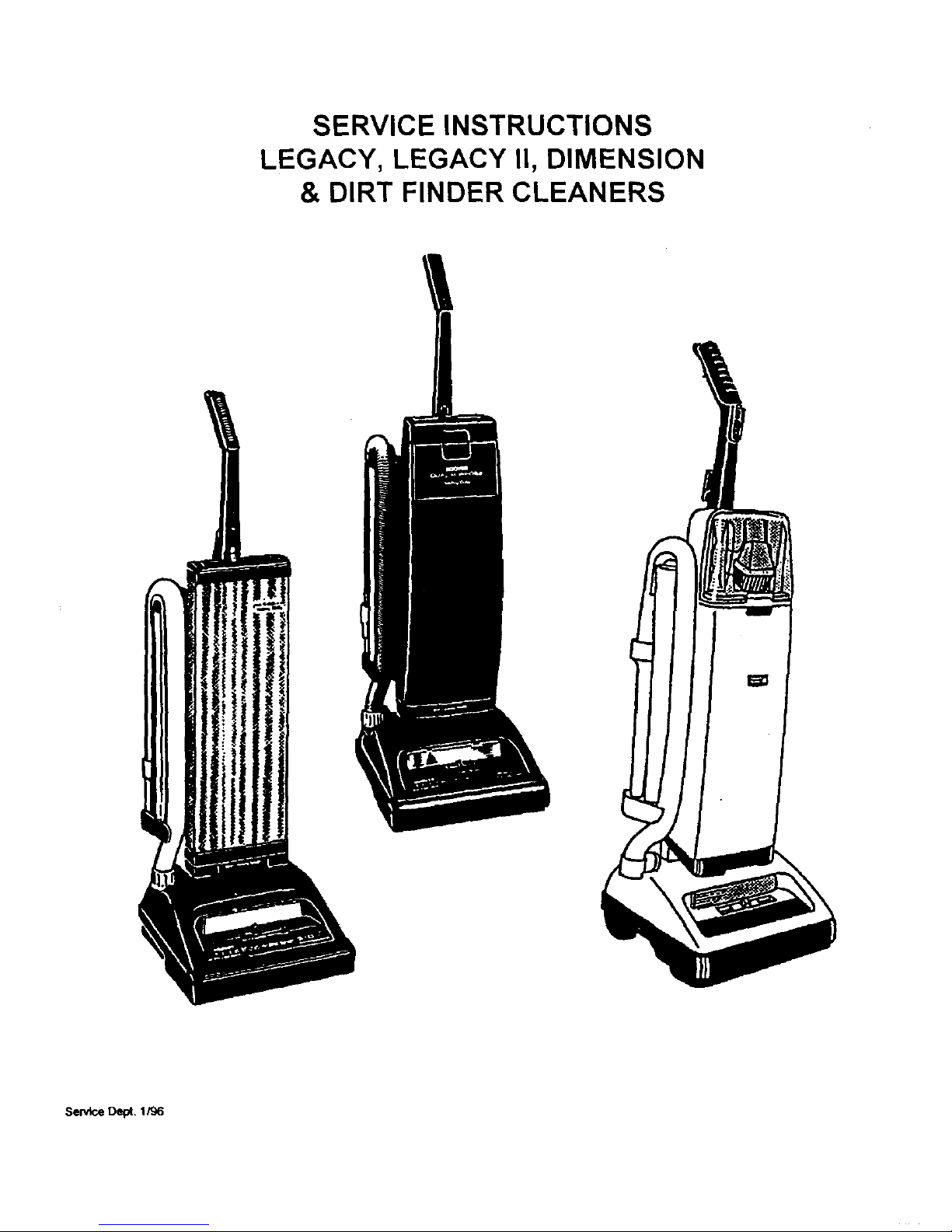
SERVICE INSTRUCTIONS
LEGACY, LEGACY II, DIMENSION
& DIRT FINDER CLEANERS
Selv_ceDept. 1/96
Page 3
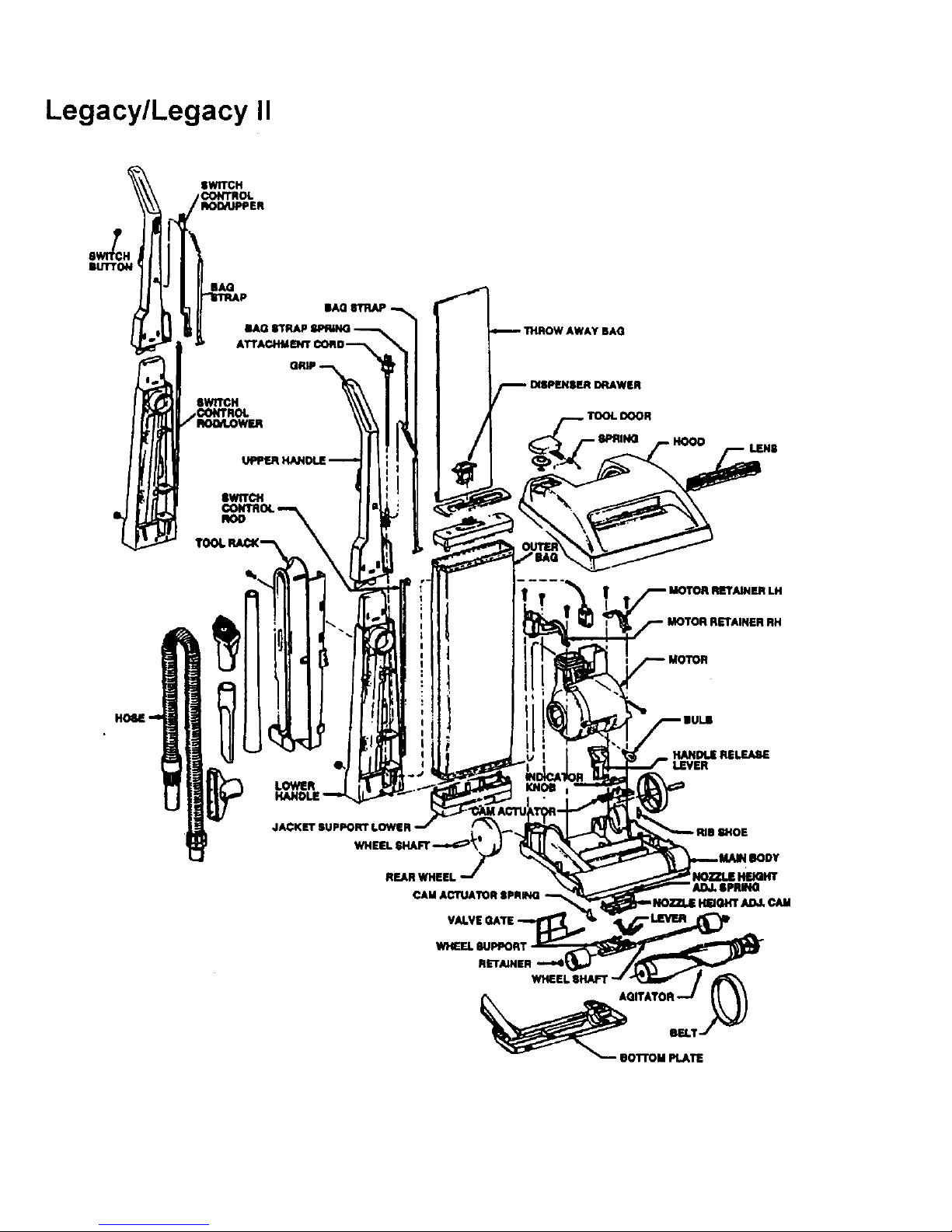
Legacy/Legacy II
SWITCH
CONTROL
BUTTON
LOWER
JACKETSUPPORTLOWER
REAR WHEEL
CAM ACTUATOR IPRING
Page 4
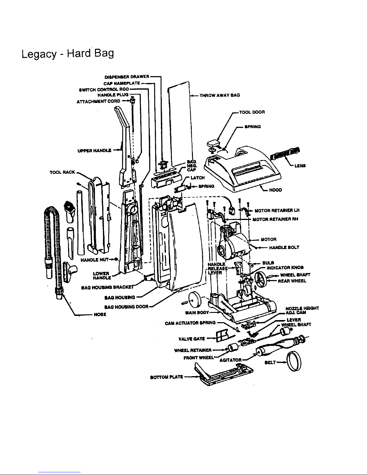
Legacy - Hard Bag
UPPl_
TOOL RACK
fBAO
TOOL DOOR
BPRING
!
MOTOR RETAINERLH
• MOTOR RETAINER RH
I
HANDLE BIJI.B
I KNOll
, WHEEL 8HAFT
NOZZLE HEIGHT
WHEEL
FRONTWHEEL* AGITATOR.
ROITOM PLATIi
Page 5
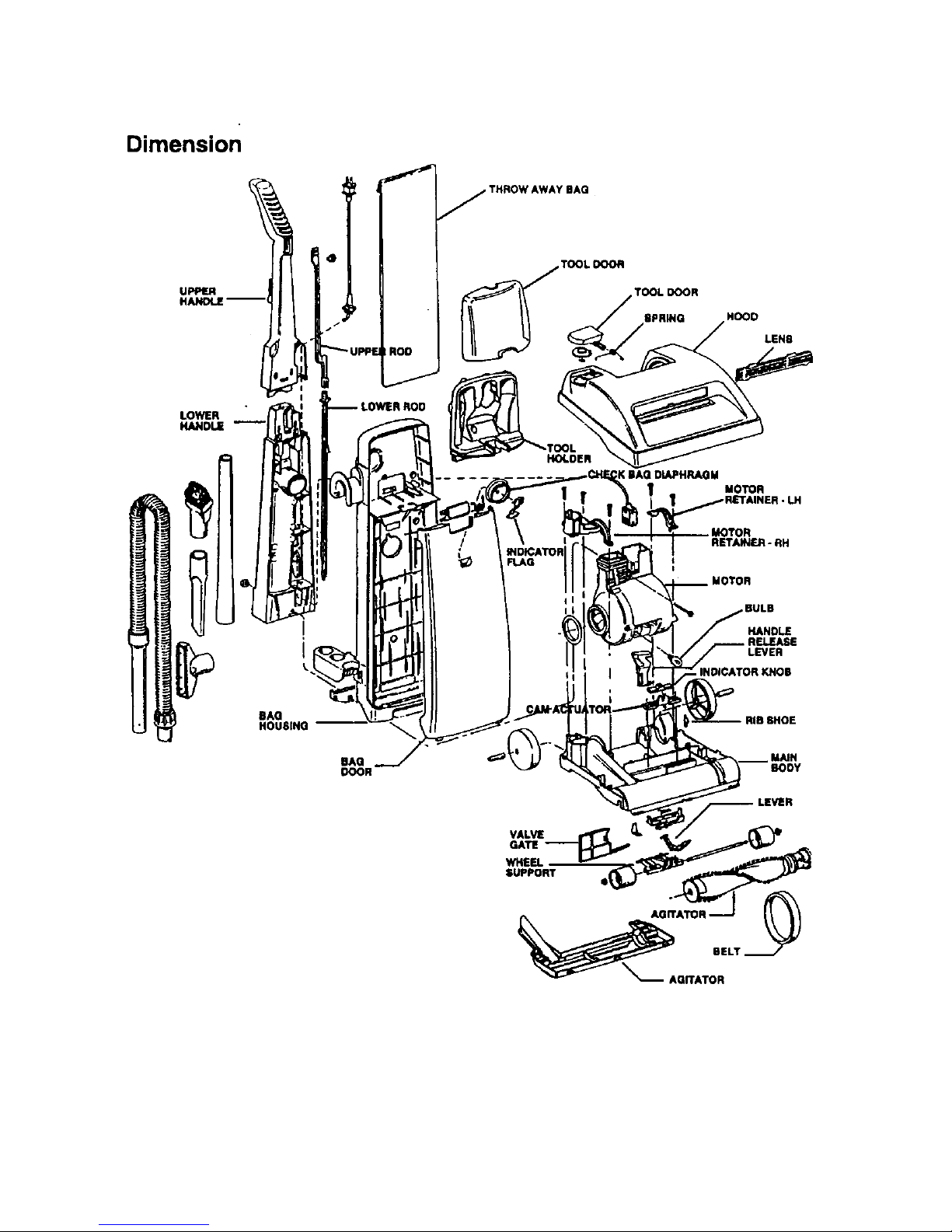
Dimension
UPPER i
LOWER
HANDLE
f
j THROW AWAY BAG
TOOL DOOR
TOOL DOOR
RPBING HOOD
LENB
.TOOL
IPPF..JROD
MOTOR
RETA)NER-RH
t
MOTOR
BULB
HANDLE
LEVER
BAG
HOUBINO --
MAIN
BODY
VALVE
GATE
WHEEl.
SUPPORT
_ AQ.ATOR
Page 6
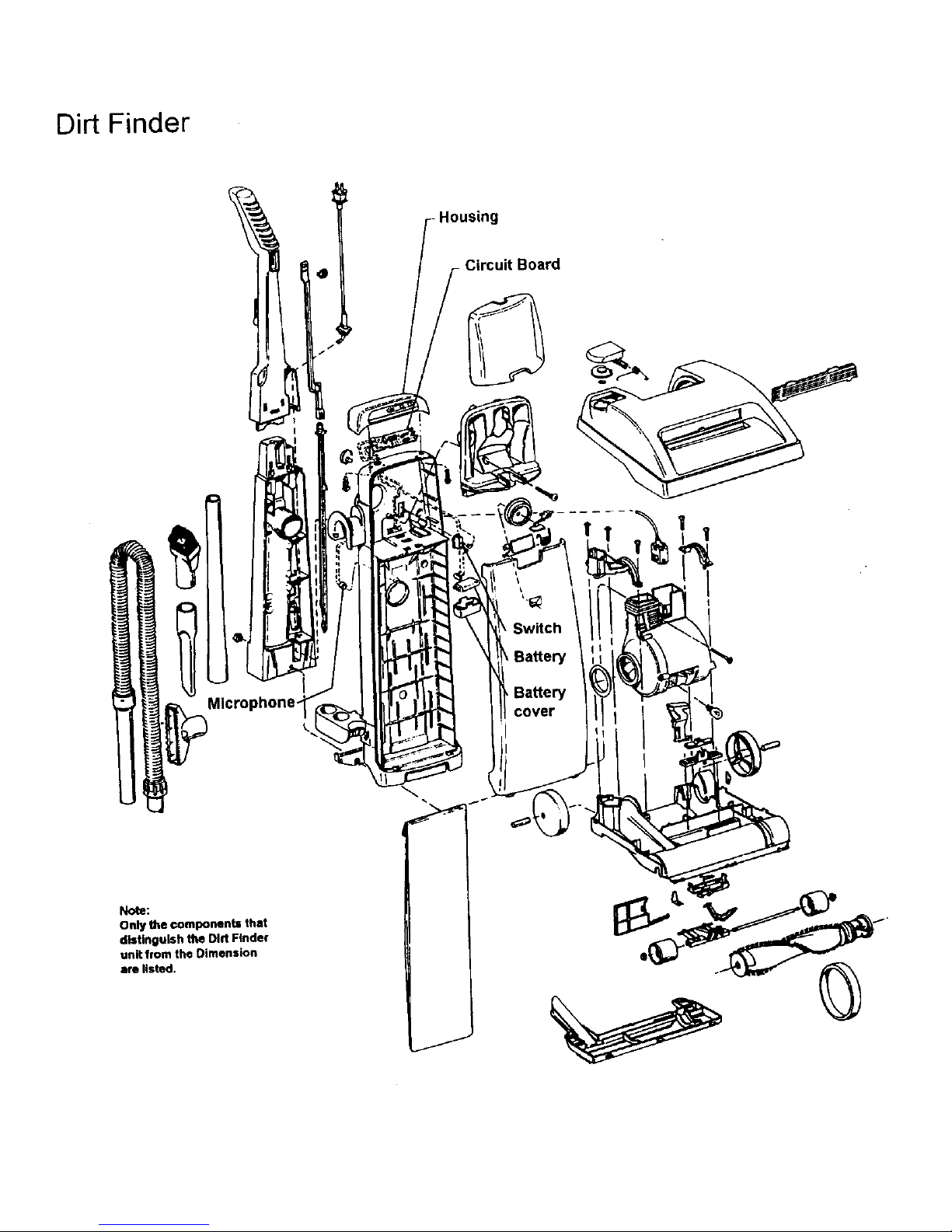
Dirt Finder
l
g
- Circuit Board
1
Microphone-
Switch
Battery
Battery
cover
I
Note;
Only the components that
distinguish the Dirt Finder
unit from the Dimension
are listed.
Page 7
I. General
These uprights are lightweight upright vacuums
that feature high performance computer design
motors, double edge cleaning, quick release cord
wraps and top conversion cleaning tools
All models have automatic height adjustment in
that the nozzle is free to float up and down on the
carpet. These models additionally have front
wheel height control to limit the minimum nozzle
height which allows the user to "select the proper
setting for optimum operation on various types of
carpets.
The Legacy and Legacy II models use Type "A"
top-fill disposable bags.
The Dimension/Dirt Finder uses Type "Z" top-fill
disposable bags.
Microfiltration bags are available for both models.
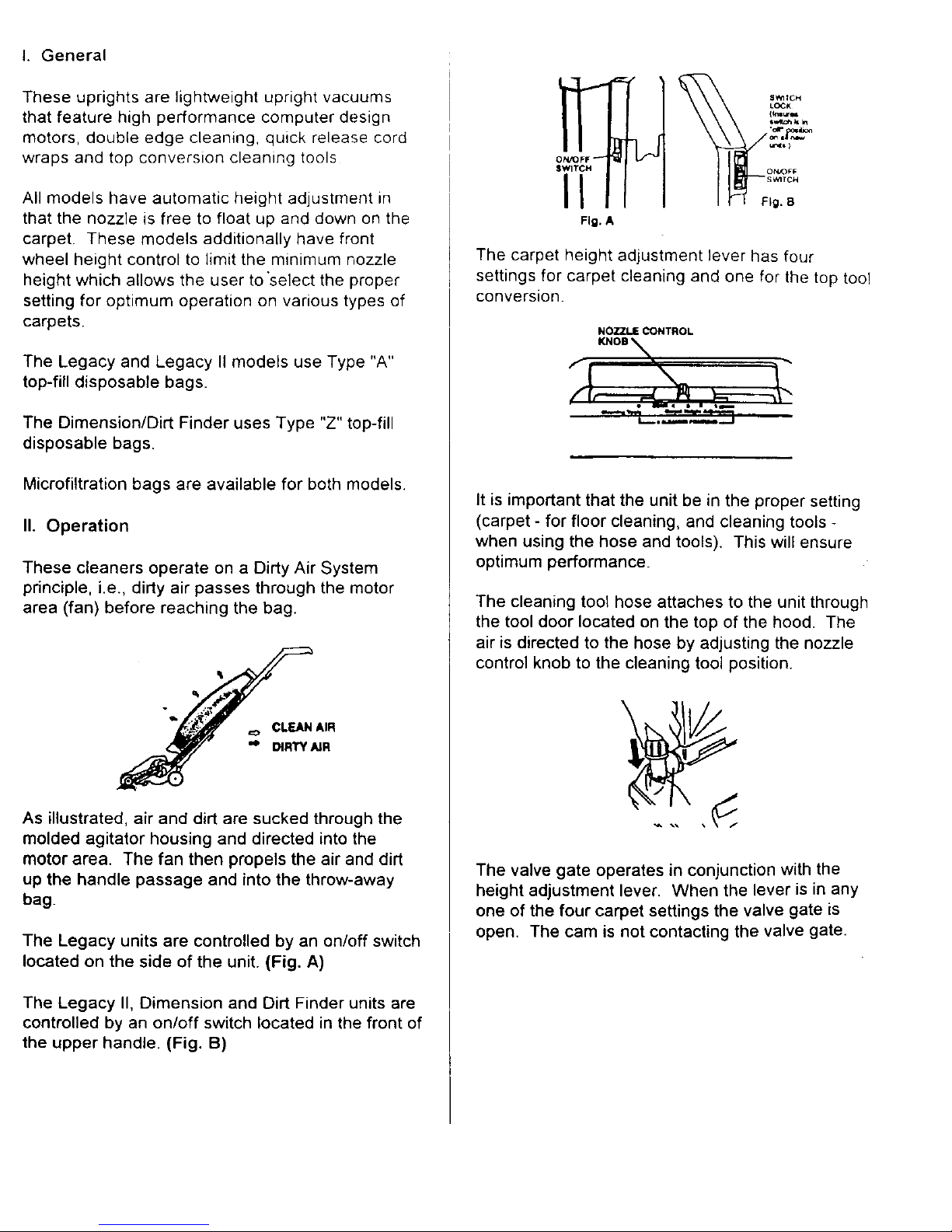
II. Operation
These cleaners operate on a Dirty Air System
principle, i.e., dirty air passes through the motor
area (fan) before reaching the bag.
=o CLEAN AIR
,o DIRTY AIR
As illustrated, air and dirt are sucked through the
molded agitator housing and directed into the
motor area. The fan then propels the air and dirt
up the handle passage and into the throw-away
bag.
The Legacy units are controlled by an on/off switch
located on the side of the unit. (Fig. A)
The Legacy II, Dimension and Dirt Finder units are
controlled by an on/off switch located in the front of
the upper handle. (Fig. B)
ON/OFF _
SWITCH
II
Fig. A
The carpet height adjustment lever has four
settings for carpet cleaning and one for the top too!
conversion.
NOZZLE CONTROL
KNOB _,_
It is important that the unit be in the proper setting
(carpet - for floor cleaning, and cleaning tools -
when using the hose and tools). This will ensure
optimum performance.
The cleaning tool hose attaches to the unit through
the tool door located on the top of the hood. The
air is directed to the hose by adjusting the nozzle
control knob to the cleaning tool position.
The valve gate operates in conjunction with the
height adjustment lever. When the lever is in any
one of the four carpet settings the valve gate is
open. The cam is not contacting the valve gate.
Page 8

Astheleveris movedto thecleaningtoolsposition
thecamlockson tothe gateandslidesitto shut
off suctiontothe agitatorcavity.
Note: These illustrations are shown without the
bottom plate or wheel assembly in place.
Dirt Finder feature:
The embedded Dirt Finder system is powered by a
regular 9V alkaline battery. The battery is located
in a holder inside the bag compartment.
The circuitryis energized when the cleaner on/off
switch is tumed to the on position. A separate
switch mounted in the bag housing is actuated by
a raised rib on the upper switch rod.
A microphone, located near dirt duct, senses
debris that strikes the tube and signals the circuit
board which controls the lights.
The green light signifies clean and the red dirty.
It is important to note that when you turn on the
unit the red light will come on. After a few seconds
the rod light will go off and the green light will come
on. This function lets you know the Dirt Finder
feature is ready. If this lighting pattern does not
occur check the troubleshooting portion of this
:instruction.
III. Disassembly
Models with a bag door skip to section B.
A. Outer bag (Legacy and Legacy II Models)
1. Release jacket support upper from bag strap
(Fig. 1).
Fig. I
2. Release outer bag retention clips (Legacy - 2
upper, 2 lower; Legacy II - 2 upper, the 2 lower
tabs are there but are not fastened) ... grasp bag
attachment collar support area and pull out. (Fig.
2)
Fig. 2
3. Remove handle bolt and nut (Fig. 3 & 4).
Page 9

Fig. 3
Fig. 4 t/
/
f
4. Remove outer bag.
Note: Re-assemble in reverse order.
The retention/guide ribs on the jacket support
lower must mate with the retention/guide ribs on
the lower handle. (Fig. 5A).
Fig. $A
Note: Units without bag door skip to Section D.
B. Bag housing (Legacy II and Dimension)
Bag housinglDirt Finder circuitry (Dirt Finder)
t. Remove bag door.
a. Pull bag door latch forward and remove door
from cleaner (Fig. 5B).
UEO_CY II
DiMENS,_N
Fig. 5B
2. Remove throw-away bag,
3, Remove bag housing.
a. Release two tabs on inside of bag housing
located above dirt tube (Fig. 5C)
/
J
Fig. 6C
Note: On Dimension/Dirt Finder models, the tool
door and holder must be removed to access the
tabs.
To remove tool door/tool holder.
1. Unsnap hinges at base of door (where
applicable to remove (Fig. 5D).
Fig. 5D
2. Remove tool holder mounting screw (located in
screw cavity under the dusting brush).
3. Pry outward on both sides of the tool holder to
release tabs and pivot holder out of position (Fig.
5E).
Page 10

Fig. 5E
b. Lift bag housing out of bag housing bracket
located on lower handle. (Fig. 5F)
Fig. 5F
C. Dirt Finder circuitry
At this point you can access the dirt finder circuitry.
This circuitry is housed in the bag housing. Fig. 5G
is a cutaway view that illustrates positioning of the
components and switch from the back of the bag
housing.
M_
Fig SH
D. Switch
1. Disconnect leads and snap switch out of bag
housing.
E. Circuit Board
1. Remove housing screws.
2. Snap circuit board out of housing and
disconnect leads.
Note: The discharge of static electricity to a circuit
board can damage the component. When
removing the circuit board from the special
anti-static bag, the following precautions should be
taken.
a. Avoid being statically charged when handling
board. Serviceman should ground himself if
possible.
b. Circuit board should be handled by outside
edge or metal heat sink only.
c. DON'T touch the metal traces (circuits) on
bottom of circuit board•
F. Microphone
The microphone is housed in the bag housing
above the opening for the dirt duct (Fig SH).
To remove:
1. Grasp microphone leads near the base of the
microphone and slowly pull the mic out of the seat.
Page 11

2. Disconnect leads at board (Fig 51)
F_.61
Note: It is important upon reassembly of the
microphone to firmly push the microphone into the
seat in bag housing. Also, replace the electrical
tape and position as iltustrated in Fig. 5H. This will
insure optimum performance of the microphone.
G. Bag housing bracket
a. Remove handle bolt and nut.
b. Remove bracket by sliding it off of the tapered
rails located on the lower handle. (Fig. 5J).
Fig. 6J
ItIULII
Ho Jacket support cap (Legacy, Legacy II
models with air freshener dispenser)
1. Remove air freshener dispenser.
2. Locate and release the two retention tabs for the
cap on the inside of the jacket. (Fig. 6).
3. Remove cap.
Fig. 6
I. Jacket support - upper (Legacy, Legacy II
models without air freshener dispenser).
1. Release 6 retention tabs on inside of jacket
support upper and separate outer bag cellar from
jacket support. (Fig. 7).
Fig. 7 _"
J. Jacket Support - Lower
1. Release 6 retention tabs on inside of jacket
support lower and separate outer bag collar from
jacket support, (Fig, 8)
FIg"II
K. Tool rack (Legacy, Legacy II models)
1. Remove tools+
2. Remove hose.
a. Rotate hose in opposite direction of indicator
arrow and remove hose. (Fig. 9)
Page 12

Flg. 9
!
3. Remove bag housing (where applicable)
4. Remove retaining screw located on the back of
the handle and remove rack. (Fig. 10).
BACK OF
HANDLE
\
Fig. 10
For proper alignment of the tool rack during
re-assembly, hook Notch A of rack on rib A of the
handle. (Fig. 11).
NOTCH A
_A
Fig, 11
L. Attachment cord - handle upperllower -
switch control rod
With jacket or bag housing, tool rack and handle
nut and bolt removed, the handle can be
disassembled by grasping and pulling upward off
of motor assembly.
IMPORTANT: Be careful not to set handle
assembly down on exposed switch rod at handle
base. This could damage rod.
1, Remove attachment cord.
a. Slide cord protector and connector out of handle
upon re-assembly, be sure to align the arrow on
the cord protector and press groove in cord
protector into slot in handle.
Press the cord into place on the three notches
indicated below.
Position the connector in the handle with the "UP"
side visible.
2. Separate handle.
a. Separate by grasping both halves and pulling
apart. (Fig. 12)
3. Remove switch control rod from the lower
handle.
Page 13

Thelowerribof theswitchcontrolrodis taperedas
shownin Fig. 13. Thisprotrusionmustberaised
to clearthesupportribin thelower handle(Fig.13)
inorderto facilitateremoval.
NOTE:EarlymodelLegacyII lowerhandle
assemblyincludesanintegralmufflersystem.This
systemconsistsof a mufflerlouver,mufflerfoam
andamufflercover.Allof theseitemsare
permanently attached to the lower handle so if a
problem related to the system occurs the complete
lower handle assembly must be replaced. This
handle with muffler is no longer available in
service.
4. Upper Handle Assembly -
The upper handle's are stocked as assemblies
only.
The serviceable components are the bag strap and
spring on models without the hard bags.
To service bag strap.
a. Remove the handle grip from the upper handle
by releasing the handle cap retention tab. (Fig. 14)
F.=
Fig. 14
The bag strap spdng is retained to the upper
handle and can now be removed in conjunction
with the bag strap (Fig. 15)
Fig. 15
J
M. Hood
1. Remove height adjustment indicator knob
(friction fit). (Fig. 16)
RO. 16
2. Turn cleaner over and remove the 4 hood
retention tabs. (Fig. 17).
Fig. 17
3. Remove hood.
Note: The furniture guard is molded onto the hood
and is not replaceable.
Air intake door assembly.
Remove door assembly by unsnapping it from the
Iocator bosses on the inside of the hood.
All the components of the door assembly listed are
replaceable.
Page 14

Headlightlens/panel
The headlight lens and/or panels are removable by
eleasing the retention tabs as illustrated (Fig. 18)
Fig. 18
N. Headlight
1. Remove hood.
2. Remove bulb by pulling straight out of socket;
push new bulb into socket until it locks in place.
O. Bottom plate
1. Place screwdriver in RH slot and remove bottom
plate.
P. Agitator - belt
1. Remove bottom plate.
2. Remove hood.
3. Remove belt from motor shaft.
4. Slide agitator and belt out of housing.
Note: When re-assembling belt, follow the diagram
on the main body for proper orientation.
For instructions concerning the agitator see
agitator section
Q. Front wheel supportJwheels/lever
1. Remove bottom plate
2. Release the cam actuator spring from the front
wheel support retaining boss and remove by
pulling it out of the main body retention pocket
(Fig. 20)
F,_.=o
3. Pivot assembly upward and remove from unit.
On Legacy units, you will encounter one of the two
wheel arrangements illustrated below. (Fig. 21,22)
Early Design
Models produced prior to 4/8/91 lever positioned
on outer edge of the support.
LEVER - EARLY DESIGN
NOT AVAILABLE
WHEEL SUPPORT -
NOT AVAILABLE
Fig. 21
Latest Design
Models produced after 4/8/91 lever positioned in
the center of the support.
The latest lever will be available in service for use
on both style supports and is a drop-in
replacement..
Page 15

E'LRLY _ _T_ST
The early design wheel supports are no longer
available in service. Updating the unit from the
early style support to the latest will require
replacement of the main body.
Wheels
Remove wheels from support by prying wheel
retainer from shaft and sliding shaft out of support.
Note: Replace the wheel retainers once they are
removed from the shaft.
Lever Remove lever by unsnapping it out of the
support.
LEVER
FRONT
WHEEL
SHAFT
WHEEL
RETAINER SUPPORT
R. Valve gate
1. Remove bottom plate.
2. Slide valve gate out of housing (Fig. 23).
Fig._i _
, Note: On the late model units, the main body has
been revised so the valve gate "snaps" into
position and is retained in the main body.
S. Nozzle height adjustment camlcam actuator
1. Remove bottom plate.
2. Remove valve gate.
3. Remove front wheel support.
4. Remove hood
5. Release the 2 nozzle height adjustment cam
retention tabs (Fig. 24)
Fig. 2_
6. Separate nozzle height adjustment cam and
cam actuator.
The spring on the cam is replaceable.
T. Rear wheels
1. Release the rear wheel shaft from the main
body retention slots. {Fig. 25)
Rg, 25
Note: The main body must be flexed on one side
or the other of the rear wheels while pulling upward
on the rear wheel shaft and then on the other side
of the rear wheel to facilitate removal,
U. Handle release lever.
1, Remove hood.
2. Lower handle to its lowest position.
3. Release the handle lever shaft protrusion from
the main body retention slots. (Fig. 26).
Page 16

V. Motor assembly
1. Remove handle.
2. Remove hood.
3. Release belt from the motor shaft.
4. Remover motor retainer right half and left half.
(Fig. 27)
Fig. 2"t
5. Lift motor off the main body. Check for the seal
at the inlet to the fan chamber. This seal is friction
fit and slides out of the housing.
Motor (See pg. 106 for exploded view)
Motor service
Serviceable components are listed on the above
schematic, Failure of any component not listed
requires replacement of the entire motor.
Fan
1. Remove light bulb by pulling straight out of the
socket,
2, Remove four screws which retain the fan
chamber to the motor end cap assembly.
3, Remove motor end cap assembly by sliding it
off the fan chamber and motor housing assembly.
4. Remove the molded duct seal by sliding it off
the housings
5. Lift off fan chamber and remove fan (LH thread)
At this point, you have broken a latex paint seal
between the motor housing and fan chamber
cover. It is important that aluminum tape be
installed in its place as shown below.
84U1001
ALUMINUM
TAPE $F.AL
FAN
CHAMBER
COVER
Motor brush holder assembly
(Replaced as an assembly which includes motor
brush and holder)
1. Remove four screws which retain fan chamber
to motor end cap assembly.
2. Slide fan chamber and motor housing assembly
out of motor end cap assembly.
3. Grasp motor brush holder assemblies with pliers
and slide then outward to release the terminal
connection.
Upon reassembly of new motor brush holder
assemblies, position holders and slide them into
place insuring the field terminal connection and
continue to insert until they stop
Do not grasp outside of brush holder with pliers as
it could damage the holder and cause the carbon
brush to stick,
Page 17

MOLDED DUCT
FAN CHAMBER
FAN
SWITCH
1
\
\
\
MOTOR
END CAP
ASSEMBLY
•" A
MOTORBRUSH 7
HOLDER J'
ASSEMBLY
Onloff switch
1. Remove fan.
2. Remove brush holders.
3. Remove armature,
4. Remove field assembly
5. Remove switch/attachment cord terminal blade.
6. Remove field winding lead from switch terminal
by uncrimping connection.
7. Remove switch by releasing switch pressure
tabs and snapping switch out of holder.
Note: When installing a new switch, the field
winding lead must be securely crimped to the
proper switch terminal.
Page 18

iV. Troubleshooting check list - Legacy/Legacy II/Dimension/Dirt Finder
-he following is a guide to aid in determining the origin of a problem for which these models could conceivably be
.Jrought in for service.
PROBLEM
POSSIBLE CAUSE POSSIBLE SOLUTION
A. Motor won't
run
1. Not firmly plugged in.
2. No voltage in customer's wall plug.
3, Onloff switch bad.
4. Open in attachment cord.
5, Open circuit in motor.
6, Fan jammed by foreign object.
7, Broken switch control rod.
1. Check power cord for proper connections.
2. Plug into known good voltage source.
3. Replace switch
4. Replace cord.
5. Check motor wiring (armature & field).
6. Remove obstruction.
7. Replace switch control rod,
B. Motor runs
cleaner won't
pickup.
1. Agitator belt broken or worn.
2. Bag full.
3. Worn agitator brushes.
4. Warped or damaged bottom plate.
5. Blocked air flow system,
6. Nozzle control knob in "cleaning
tools" position,
1. Replace belt.
2. Replace throw-away bag.
3. Replace agitator.
4, Replace bottom plate.
5. Clear blockage,
6. Adjust to one of the four carpet cleaning
positions.
C, Motor
intermittent
D. Motor runs
hot
1. Loose wire connection.
2. Defective onloff switch.
3. Worn carbon brushes.
4. Motor brush hanging in holder.
1. Refer to 2 and 6 under Item B
2. Worn carbon brushes.
3, Shorted or overloaded field coil.
4. Shorted or ovedoaded armature,
5. Loose wire connection.
6. Motor air vent clogged.
7, Tight motor bearings.
1. Check all connections.
2. Check and change switch.
3, Replace motor brush holder assembly.
4. Replace motor brush holder assembly.
1. The items referred can cause the motor to
run hot because all restrict the air supply.
Field and armature will be generally dis-
colored, Replace motor.
2. Replace motor brush holder assembly.
3. Replace motor,
4. Replace motor.
5. Connections should be tight to prevent
high resistance, Tighten connections or
replace as necessary.
6. Clear air restriction.
7. Check and replace motor if necessary.
E. Cleaner noisy t. interference between bottom plate
and agitator.
2. Broken blade(s) on fan,
3. Agitator bearings dry or worn.
4. Warped agitator,
1. Check to see if bottom plate is damaged
or mispositioned.
2. Replace fan.
3. Grease or replace bearings.
4. Replace agitator.
F. No pickup
using tools
1. Cleaner not set to "cleaning tools"
position.
2. Obstruction in hose.
3. Valve gate not functioning.
1. Check setting.
2. Clear obstruction.
3. Remove bottom plate and check operation
Page 19

This section addresses problems associated with the Dirt Finder feature in the Dirt Finder unit
PROBLEM POSSIBLE CAUSE
POSSIBLE SOLUTION
A. Circuit board
won't light
1. 9V battery not installed.
2. Low battery.
3. Battery disconnected.
4. Switch failed.
5. Switch out of position.
6. Wires not connected at switch or
circuit board.
7. Circuit board failed
8. Bag housing not firmly locked
into place.
1. Install battery and check operation.
2. Change battery.
3. Connect and check operation.
4. Replace switch.
5. Check switch mounting bracket to insure its in
position and switch is snapped into bracket.
6. Check and reconnect.
7. Replace board (check items 1 - 6 first)
8. Check that housing is snapped into place. This
will insure raised projection on switch rod
contacts switch.
Note: Normal lighting pattern is discussed in the basic operation section of this
instruction
B. Light does not
change from
green to red
during normal
operation
1. Carpet clean. 1. The red light may seldom come on during
cleaning. This means your cleaner is picking up
primarily fine surface dust and lint which the
system may not detect or that the carpet is clean.
Switch unit to Hi - sensitivity and recheck.
Note: To check lighting pattern, unplug unit, turn cleaner switch to on (green light will
illuminate). Tap inside the opening of the dirt duct with a screwdriver. The light
should change from green to red. If the light does not change, check the following.
1. Microphone out of position.
2. Dirt duct opening "caked with
dirt"
3. Microphone leads disconnected
from circuit board.
4. Microphone failed.
1. Check to insure the mic is firmly pressed into
the seat.
2. Clean opening and recheck.
3. Check and reconnect.
4. Replace microphone (Check 1 - 3 first).
Page 20

Troubleshooting Guide
Legacy & Legacy II
Page 21

The following Jsa guide to aid in determining the origin of a problem for which these models could conceivably be brought
in for service
PROBLEM POSSIBLE CAUSE POSSIBLE SOLUTION
A. Motor won't
Fun
1 Not firmly plugged in 1
2. No voltage in customer's wall plug 2.
3 On/off switch bad 3
4 Open in attachment cord. 4.
5. Open circuit in motor. 5.
6 Fan jammed by foreign object. 6.
7. Broken switch control rod. 7
8. Crimped connections for field wires loose 8.
9 Motor brushes worn or stuck in holder 9.
10. Motor bearing(s) failed - seized 10,
Check power cord for proper connections
Plug into known good voltage source
Replace switch
Replace cord.
Check motor wiring armature & field).
Remove obstruction.
Replace switch control rod.
Check and re-crimp or solder,
Replace motor brush holder assembly.
Replace. Cleaner will hum loudly when energized
if this condition exists.
B. Motor runs
cleaner
won't
pickup
1. Agitator belt broken or worn.
2. Bag full.
3. Worn agitator brushes.
4. Warped or damaged bottom plate.
5. Blocked air flow system.
6. Nozzle control knob in "cleaning
tools" position.
7. Carpet height adjustment lever in "cleaning
tools" position.
8. Fan blades worn or fan stripped.
9. Bottom plate mis-positioned. Not sealing
10. Valve gate shifted to close off agit. cavity.
11. Tool door seat missing or worn.
1. Replace belt.
2. Replace throw-away bag.
3. Replace agitator.
4. Replace bottom plate.
5. Clear blockage.
6. Adjust to one of the four carpet cleaning
positions.
7. Set to one of the four "carpet heightadjustment"
settingswhen usingfor floor cleaning.
8. Replace fan
9. Repositionand recheck operation.
10. Check positionand functionof valve gate. Height
adjustment cam should pull valve gate to open
agitator cavity when moved to the "carpet height
adjustment" settings.Check to insurevalve gate is
not staying closed.
11. Replace seal. This applies to models without
permanently attached hose.
C. Motor 1.
intermittent 2.
3.
4.
Loose wire connection.
Defective on/off switch.
Worn carbon brushes.
Motor brush hanging inholder.
1. Check all connections.
2. Check and change switch.
3. Replace motor brush holder assembly.
4. Replace motor brush holderassembly.
D. Motor runs
hot
1. Refer to 2 and 5 under Item B
2. Worn carbon brushes,
3. Shorted or overloaded field coil.
4. Shorted or overloaded armature
5. Motor air vent clogged.
6 Tight motor bearings.
1. The items referred can cause the motor to
runhot because all restdct the air supply.
Field and armature will be generally dis-
colored. Replace motor.
2. Replace motor brush holderassembly.
3. Replace motor.
4. Replace motor.
6. Clear air restriction.
7. Check and replace motor if necessary
Page 22

PROBLEM POSSIBLE CAUSE
POSSIBLE SOLUTION
E Cleaner
noisy
1 Interference between bottom plate
and agitator
2 Broken blade(s) on fan
3. Agitator bearings dry of worn
4. Warped agitator
5 Belt worn- slipping.
6 Objects lodged in fan or fan chamber
7 Motor bearing(s) failed
1 Check to see if bottom plate is damaged
or mis-positioned
2 Replace fan.
3. Grease or replace bearings
4. Replace agitator.
5 Replace belt.
6. Clear obstruction. Check condition of fan.
7 Replace motor.
F. No pickup 1 Cleaner not set to"cleaning tools"
using tools position
2. Obstruction in hose.
3. Valve gate not functioning.
1.
2.
3.
Check setting.
Clear obstruction.
Check position and function of valve gate. Height
adjustment cam should push valve gate to close off
agitator cavity when moved to "cleaning tools"
position. Also, a mis-positioned bottom plate will not
"trap" the gate to allow for proper function.
4. Valve gate missing.
5. Hole in hose
6. Loose or leaking hose ends.
4. Replace and check operation.
5. Replace hose.
6. Check to insure both ends are tight.
G. Dirt/Dust
leakage
inside
cleaner.
1. Seal at inlet to motor damaged.
1.
2. Seal at exit of fan chamber missing or 2
damaged.
3. Leakage at junction of fan chamber cover to 3.
motor housing.
4.
4. Loose motor retainer cap(s).
.5. Fan chamber or cover cracked.
Check and replace if necessary. A cardboard
template should be used over the face of the seal
when sliding motor into housing. Template size
should match the size of the seat.
Replace if missing or damaged.
In production, a latex paint seal is used to seal this
junction. If the motor is disassembled, this seal is
broken. Clean area and apply aluminum tape (Part
no. 54821001) at this junction.
Tighten. Handle will also be very unstable if this
condition exists.
Replace.
H Belts
continually
breaking.
1. Off brand belt being used.
2. Agitator"dragging"
3. "Belt end" motor bearing failing. Armature
shaft overheating.
1. Install genuine Hoover belt and check.
2. Check for worn agitator bearings, worn or missing
thrust washers and thread or carpet fiber built up
under thread guards. Belt should be melted in area
of break if this condition exists.
3. Replace motor. Belt should be very tacky if this
condition exists.
I. Cleaner nozz. 1.
will not raise 2.
when handle
is put into
upright pos.
Lever on wheel support missing or broken.
Boss on motor which contacts lever broken
1. Replace lever.
2. If broken, replace motor housing.
 Loading...