

Page 1
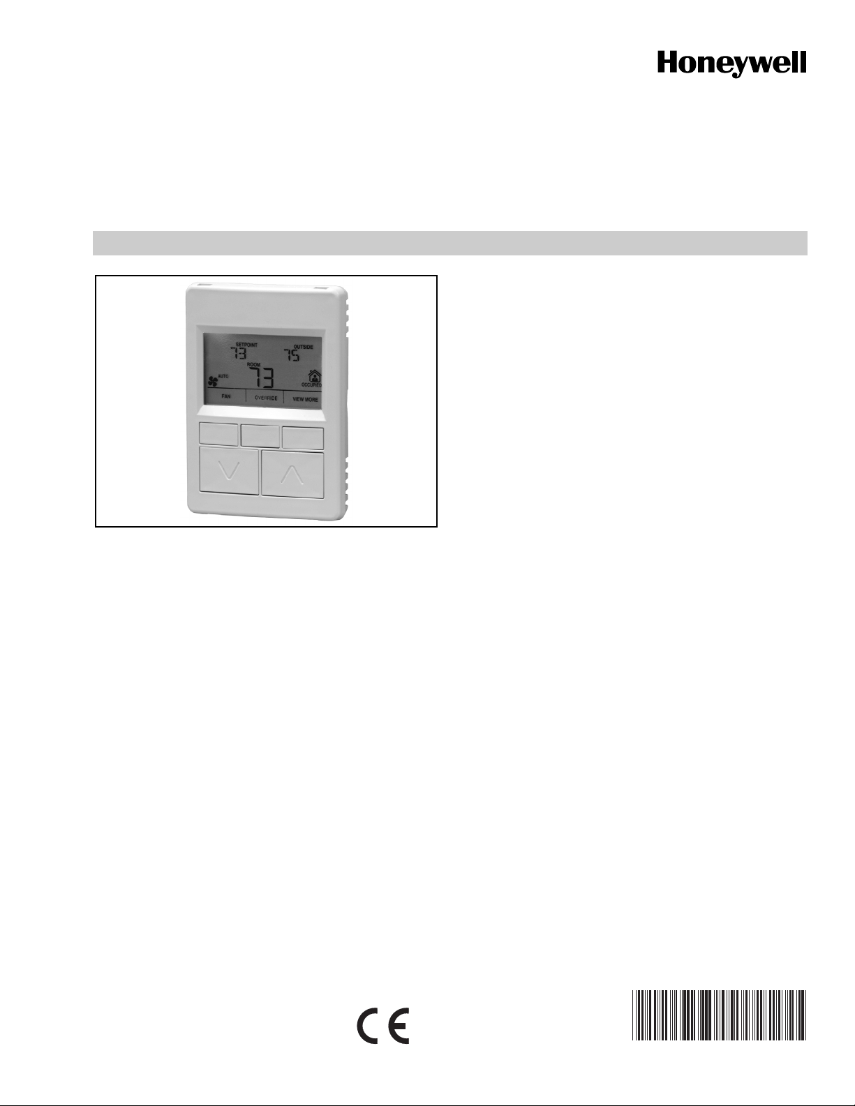
Zio™ LCD Wall Modules
TR70 AND TR70-H with Sylk™ bus
• Programmable for: Home screen options, tenant
• Eight pre-programmed configurations (e.g. VAV with
• Ability to access and adjust most parameters in the
• Ability to balance the VAV system from the wall
• Home screen can display one to three of any of the
• Network bus jack.
• Simple 2-wire terminal connection to the
GENERAL
The TR70 and TR70-H are 2-wire, non-polarity sensitive,
Sylk bus communicating wall modules for use with Spyder™
(PUL6438S, PVL6436AS, and PVL6438NS models only) and
ComfortPoint™ (CP-UL6438S, CP-VL6436AS, and
CP-VL6438NS models only) programmable controllers.
All models have a space-temperature sensor, network bus
jack, and an LCD panel with three softkeys and two Up/Down
adjustment keys. The TR70-H model includes an onboard
humidity sensor.
NOTE: Refer to the Zio™ LCD Wall Modules TR70 and
TR70-H with Sylk™ bus – Operating Guide (form
63-2667) for information about customizing the wall
module configuration, such as modifying the default
Home screens or creating your own application.
FEATURES
The TR70 and TR70-H wall modules include:
• Ability to control user access to controller parameters.
• Customized parameter access, by using the Tridium
Niagara Workbench tool.
• Retention of user configuration, including setpoints
SPECIFICATIONS
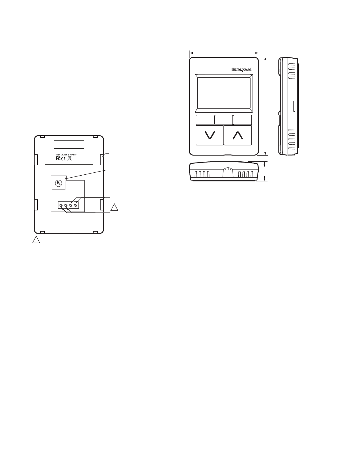
Construction: Two-piece construction, cover and internally
Mounting Options: The LCD wall modules can be mounted
Dimensions (H/W/D): See Fig. 2 on page 2.
Environmental Ratings:
Temperature Setpoint Range: Default range is 55°F to 85°F
Temperature Sensor Accuracy: ±0.36°F at 77°F (±0.2°C at
SPECIFICATION DATA
access, contractor access, access to controller
parameters, setpoint, override, fan, and other
parameters.
balancing) in the wall module configuration tool.
programmable controller (except Scheduling).
module.
following parameters: Temperature Setpoint, Room
Temperature, Room Humidity, Outdoor Humidity,
Outdoor Temperature, and Time, or one of virtually any
parameter in the controller.
programmable controller and an optional 2-wire
terminal connection for the network. All connections
are polarity insensitive.
after a power outage.
wired subbase. Field wiring, 18 to 24 AWG (0.82 to 0.20
sq. mm), connects to a terminal block in the subbase.
on a standard two by four inch junction box or on a 60 mm
diameter junction box. The modules may be mounted up to
200 ft. (61 m) from the programmable controller. Twisted
pair wiring is recommended for distances longer than 100
ft. (30.5 m).
Operating Temperature: 30°F to 110°F (-1°C to 43°C)
Shipping Temperature: -40°F to 150°F (-40°C to 65.5°C)
Relative Humidity: 5% to 95% non-condensing
(10°C to 35°C); configurable for other ranges.
25°C)
63-1322-01
Page 2
ZIO™ LCD WALL MODULES
Humidity Sensor Accuracy (TR70-H only): ±5% RH from
20% to 80% RH
Power: 18 Vdc power is supplied to the wall module from the
2-wire S-BUS connection to the programmable
controller.
Accessories: 50007298-001 (pack of 12) medium, cover
plate; 6-7/8 x 5 in. (175 x 127 mm).
Approvals:
CE; UL94-HB plastic enclosure; FCC Part 15,
Class B
Terminal Wiring Location
Fig. 1 illustrates the location of the terminal block and other
features on the TR70 and TR70-H wall modules.
NET-2
(optional)
S-BUS
4321
S-BUS
HONEYWELL
PATENT PENDING
GOLDEN VALLEY,MN
ASSEMBLED IN MEXICO
SLOTS FOR SUBBASE
LOCKING TABS (X4)
WALL MODULE BUS
ADDRESS DIAL
(DEFAULT SETTING = 1)
S-BUS PROGRAMMABLE
CONTROLLER CONNECTION
1
NETWORK BUS
CONNECTION
M27349
NET-1
(optional)
TR70-H
YY WK
50028668-XXX
2
1
3
0
4
9
5
6
8
7
1 2 3 4
EACH OF T HE TWO WIRE CO NNECTI ONS FOR THE S- BUS AND NETW ORK
1
BUS TERM INALS ARE PO LARITY IN SENSITIVE.
Fig. 1. LCD wall module components (rear view of TR70).
NOTES:
1. 18 Vdc power for the LCD wall modules is supplied from the programmable controller.
2. Each of the 2-wire connections for the network
bus and S-BUS are polarity insensitive.
Module Dimensions
3 5/16 (84)
4 5/8
(117)
15/16
(24)
M27347
Fig. 2. Wall module dimensions in inches (mm).
Communications
The wall modules use a sensor bus (S-BUS) for
communications with the programmable controller.
For network communication, the building’s LON network wires
connect to the two terminals (NET-1 and NET-2). See Fig. 1.
A network bus port is accessible at the bottom of the wall
module by removing the jack plug.
The network bus and S-BUS terminals (see Fig. 1) are
insensitive to polarity, minimizing installation errors due to
mis-wiring. The recommended wire size for the network bus
and S-BUS is Level IV, 22 AWG (0.33 sq. mm) plenum or nonplenum rated, unshielded, twisted pair, solid conductor wire.
LCD Display
The LCD display may be customized for tenant and contractor
users. The following are a few samples of the various Home
screens that are configurable for the LCD Wall Modules. Not
all possible Home screens are illustrated here. There are
many other configurable Home screens.
63-1322—01 2
NOTES:
1. Home screens can display one to three of any of
the following parameters: Temperature Setpoint,
Room Temperature, Room Humidity, Outdoor
Humidity, Outdoor Temperature, and Time, or one
of virtually any parameter in the controller.
2. Refer to the Zio™ LCD Wall Modules TR70 and
TR70-H with Sylk™ bus – Operating Guide (form
63-2667) for information about customizing the
wall module configuration, such as modifying the
default Home screens or creating your own application.
Page 3

Sample Tenant LCD Displays
The Fan and Occupied settings are optional for Home screen
setup. If there are no parameters configured for Tenant
access, the “View More” softkey does not display on the
Tenant Home screen.
The following are a few samples of the various Home screens
that are configurable for the LCD Wall Modules. Not all
possible Home screens are illustrated here. There are many
other configurable Home screens.
M27354
Fig. 3. Sample Tenant Home screen with System Status,
Setpoint, Outside Temperature, and
Room Temperature (predominant).
ZIO™ LCD WALL MODULES
M27356
Fig. 6. Sample Tenant “View More” display showing
CO
sensor value from controller.
2
NOTE: Any configured parameter may be displayed.
Sample Contractor LCD Displays
The Contactor mode allows advanced options using the
softkeys. Contractor mode also allows for customizing the
Tenant view, including setting the tenant’s Home screen and
“View More” access.
M27379
Fig. 4. Sample Tenant Home screen with Room
Temperature and Time (predominant).
M27377
Fig. 5. Sample Tenant Home screen with
Setpoint display only.
M27357
Fig. 7. Sample Contractor Home screen display with
System Status, Setpoint, Outside Temperature,
and Room Temperature (predominant).
CONTACTOR HOME SCREEN SOFTKEYS
The three softkeys on the Contractor Home screen (Fig. 7)
provide the following:
SET HOME SCREEN - allows the contractor to choose
among multiple Home screen options for the tenant.
SET VIEW MORE - allows the contractor to give additional
parameter access (view only or adjustable) to the tenant.
PARAMETERS - allows the contractor to monitor and/or
adjust parameters in the programmable controller.
3 63-1322—01
Page 4

ZIO™ LCD WALL MODULES
M27358
Fig. 8. Sample Contractor parameter display showing
user-created discharge air parameter value.
M27359
Fig. 9. Sample Contractor parameter display showing
sensor setpoint value (CO2 sensor from controller).
NOTE: Any configured parameter may be displayed.
TYPICAL SPECIFICATION
1. The wall module shall have an LCD display.
2. The wall module shall have a customizable home
screen:
a. Shall have the option to show up to 3 parameter
values on a single display.
b. Shall have the option to show occupied status.
c. Shall have the option to show system status.
d. Shall have the option to show fan status.
e. Shall have the option to show up to three of the
following parameters:
(a) room temperature, setpoint, outside tempera-
ture, room humidity, outside humidity, time of
day.
f. Shall have the option to show on the home screen
any single parameter in the controller, with a user
defined 8 letter name.
3. The wall module shall offer access to all parameters
necessary to balance a VAV system.
4. The wall module shall offer the ability to restrict access
to parameter information with keypad enabled lock out.
5. The wall module shall retain user configuration including
setpoints after power outage.
6. The wall module shall use a two wire polarity insensitive
connection for all communication and power needs.
7. The wall module shall offer the ability to access and
adjust user chosen controller parameters.
8. The wall module shall offer the ability for the tenant to
adjust override time period within the limits set by the
contractor.
9. The wall module shall offer a communication jack for
remote access to the network.
10. The wall module shall offer a ± 5% on board humidity
sensor (TR70-H only).
11. The wall module shall be configured through the Tridium
Niagara workbench tool.
12. The wall module shall communicate with other devices
using the Sylk bus protocol.
ComfortPoint™ is a trademark of Honeywell International Inc.
L
ONMARK® is a trademark of the LonMark Association.
Spyder™ is a trademark of Honeywell International Inc.
Sylk™ is a trademark of Honeywell International Inc.
Zio™ is a trademark of Honeywell International Inc.
Automation and Control Solutions
Honeywell International Inc. Honeywell Limited-Honeywell Limitée
1985 Douglas Drive North 35 Dynamic Drive
Golden Valley, MN 55422 Toronto, Ontario M1V 4Z9
customer.honeywell.com
® U.S. Registered Trademark
© 2008 Honeywell International Inc.
63-1322—01 M.S. 10-08
 Loading...