

Page 1
Comfort Compact Controller ZG 215VN
OPERATION AND PUTTING INTO SERVICE
142 376
5
B
BC
ZG215 VN
auto1
P1 CB
L1 L2 P1
///
C( )
0
-8
P1
S
8311.7151
CB
C
CB50268
B
A
Page 2
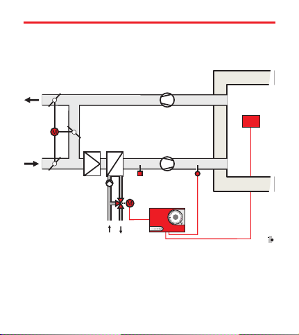
Constant discharge temperature control
TW
V
FT
LF
VM
DR
ZG 215VN
/////
//
///
CB2282
ZG Control Unit
VM Servomotor
DR Heating mixing valve
LF Air flow sensor
TW Temperature selector (opt.)
FT Frost protection thermostat
V Air heater
Page 3
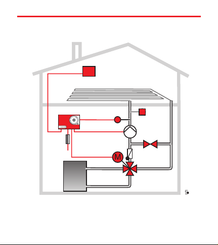
Constant flow temperature control for a
floor heating system
TW
ZG215VN
////
ZG Control Unit
VM Servo motor
ZR Heating mixing valve
VF Flow sensor
VF
//
////
VM
////
P
ZR
TW Temperature selector
T Temperature limiter
P Heating circuit pump
T
CBZG107.cdr
Page 4

Operating the Control
The ZG 215VN can be used at choice for the control of an
air-handling system’s constant discharge temperature (left-
hand system diagram) or a floor heating’s constant flow tempe
rature (right-hand system diagram).
TheVF/LF temperature sensors monitor constantly the actual va
lues and transmitthese values to theZG control unit. Should the “
temperature or the supply temperature deviate from the target va
lue, the controller commands the VM servo motor to adjust the
ZR/DR mixing valve.
The mixing valve performs the necessarychange tothe mixing ra
tio betweenthe heated supplywater and theheating circuit’s retur
ning cooled water.
TheTW temperature selector is used as remotecontrol. By means
of theP2 selector knobthe flow or supplytemperature can be mo
dified. The temperature selector is not absolutely necessary in
functional terms, but it makes the operation easier.
The FT frost protection thermostat (air-handling system only)
works independentlyfrom the controlunit and protects theair hea
ter against freezing.
-
-
-
-
-
-
-
Page 5

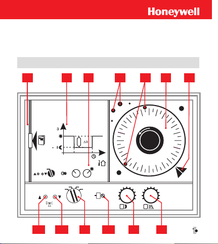
Operating and Display Components
Pos. Function Basic Setting
B Day mode
C Reduced mode
P1 Sensitivity 5
S Operating mode selector auto
L1 ”Hotter“ LED (red)
L2 ”Colder“ LED (green)
1 Instructions compartment
2 Heating curve diagram
3 Basic Settings
4 Reserve trip pins
5 Inserted trip pins
6 Timer (optional)
7 Pointer for the current time
Settings on the Temperature Selector
P2 Selector knob
Page 6

Operating Mode Selector
manu The control unit is deactivated (the timer runs).
The mixing valve can be set manually (by hand).
The pump is switched on.
auto Recommended setting for higher energy saving:
automatic change between day and reduced mode
according to the timer with night switch-off.
Only night mode, timer not active.
Constant reduced mode according to the settings on
the setting knobs B minus C , the timer remains
inactive.
Page 7
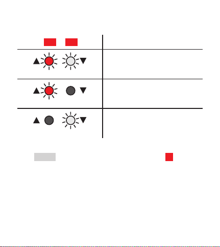
LED’s
L1 L2
Both LED’s light up:
”neutral“
– mixing valve stops
only red LED lights up:
”hotter“
– mixing valve opens
only green LED lights up:
”colder“
– mixing valve closes
In themanu settings ofthe operating modeselector S there isno
LED display.
Page 8

Putting into service
Set the timer 6 with the current time
n
Set the operating mode selector S to auto
n
The remaining basic factory settings are printed under 3 on the
control unit.
Timer for reduced mode 6
With theaid of thetimer, the roomtemperature during idleperiods
can be reduced automatically to save on operating costs.
The timer has a built-in power reserve of approx. 60 hours thanks
to a rechargeable battery.
Page 9

Changing the program
Factory settings: red pin 6:00, bluepin 22:00.
Pull out the trip pin and insert it again at the desired
n
switch-on time. Push in the trip pins until they reach the
stop!
Owing to the different lengths, the trip pins must always be inser
ted in a red/blue alternate ordere. Thered trip pinswitches on day
mode, while the blue pin activates reduced mode.
In order tomake sure that the rooms areheated well in the morning,
the heating system’sday mode should be activatedbetween a half
an hour and an hour before using the rooms.
Energy saving tip: Reduced mode can be activated
up to an hour before the room is left. The storage
capacity of the heating system and building is
enough to keep the rooms warm for some time.
Timer with day program
The day program is repeated every 24
hours. Ifa (second) decrease intempera
ture is desired in thecourse of the day to
save energy,the program needs tobe ex
tended. Take the extra trip pins 4 and
insert them at the desired time.
-
-
-
CB5044.7.cdr
Page 10

Example:
Desired time program
Normal temperature: 6:00 h to 8:00 h and 16:00 h to 22:00 h
Night decrease: 22 :00 h to 6:00 h
Day decrease: 8:00 h to 16:00 h
Position of the trip pins
red pin 6:00 h – Start day mode (normal temperature)
blue pin 8:00 h – Start day decrease
red pin 16:00 h – Start day mode (normal temperature)
blue pin 22:00 h – Start night decrease
Timer with week program
The timer has a changeable dial.
With the week program, dialling a different heating program for
each weekday is possible.
The dial isprepared ex factory for theday programand, if required,
it can bechanged toweek program (see installationinstructions).
Setting the right time
To set the time, the time dial is to be placed on the trip pins and
turned clockwise until the indication on the setting marker 7
matches with the current time.
Page 11

Optimization of the Settings
The ZG 215VN control unit is a constant temperature controller.
The desired temperature, e. g. the supply temperature of an
air-handling system or the flow temperature of a heating system
can be set on the setting knobs B and C of the controller.
Day mode (setting knob B )
The selectingrange onthe setting knob B varies from0 to 100°C.
Normally the setting knob B sets the desired target value for day
mode.
If a temperature selector is used as a
remote control, the setting knob B is to be
set on 20.
Reduced mode (setting knob C )
By meansof setting knob C , the intensity ofthe decrease tobe ac
tivated withthe timercan be set. The settingrange varies from 0 to
-100 K (°C). The decrease set with setting knob C refers to the
temperature either on setting knobBor on the TW.
Example (without TW)
n
Setting on the setting knob B è 50
Setting on the setting knob C è
i. e. for normal mode (day mode): constant target value of 50 °C,
for reduced mode (night) a target value of 30 °C.
-20
-
Page 12

Example (with TW 23)
n
Setting on the setting knob B è 20
Setting on the TW 23’s selector knob P2 è 50
Setting on the setting knob C è -20
Both settings give target values of 50 °C in the day and of 30 °C at
night.
Setting the target value
Temperature selector TW 21 to 23
When using a temperatureselector the setting knob B on thecon
troller is always to be set on 20. The setting of the selector knob
P2 on the TW is relevant for the target value.
There are temperature selectors for various temperature ranges:
TW 21 – settable temperature range -15... + 15° C
TW 22 – settable temperature range 0… 30 °C
TW 23 – settable temperature range 20… 70 °C
If notemperature selector isavailable, the desiredtarget value isto
be set on the setting knob B of the control unit
Energy saving tip:
Set the operating mode selectorSon .
The controller hence works constantly in reduced
mode.
-
Page 13

Troubleshooting Checklist
Is the heat generator at the required temperature?
n
è Read the heat generator’s thermometer.
Is the burner ready?
n
Is the burner failure lamp on?
è If necessary, press the reset button.
Was the temperature selector set by mistake?
n
Setting of the selector knob P2
Check the setting of the control unit.
n
Setting knobs BCand operating mode selector S .
Is the timer running? Is the displayed time correct?
n
è Check the time and switch-on point.
If the problem still has not been solved after checking the settings,
position the setting knob B on +7
The servomotor should now open the mixing valve and the red
LED L2 should light up. Ifthis is not the case, the control system
has failed. Contact your heating technician.
Page 14

Manual mode
CB5043.7.cdr
Page 15

Manual mode (fig. on the left)
In case of the breakdown of the heating mode regulation, you can
proceed temporarily as follows:
1. Set the operating mode selector S on manu .
n
2. Open the mixing valve by hand until the desired flow and
n
room temperatures are reached.
– The coupling incorporated in the mixing valve drive unit
provides for the release of the connection between the
motor and the mixing valve.
– Press firmly on the unlock key on the cover of the drive
unit and keep the key pressed (firmly!).
– Use the setting lever to set the mixing valve in the
desired position.
After eliminating the problem, the mixing valve is
set again to the right position by the control unit in
automatic mode.
Page 16

Behavior of the target values
during day and reduced mode
B
BC
Day mode setpoint
C ()
///
Reduced mode
setpoint
Page 17

Instructions for the Technician (only!)
Removing the Timer
(see also the installation instructions)
Operating steps:
1. Pull out the instructions case.
n
2. Hold the timer by the two white stems and turn to the left
n
until the connector is released.
3. Remove the timer.
n
(To install the timer proceed in the opposite order.)
Regulation Stability (Sensitivity)
The stability of the regulation can be modified with the setting
potentiometer P1 .
For the regulation technician:
By means of P1, set the proportionalrange ofthe PD control unit.
Recommended basic setting: P1 è 10.
In case of unstable regulation set higher values.
Page 18

Flow- and airflow-sensors
LF20
VF 20AVF20
Page 19

Reference
Installation instructions
Compact Control Units ZG 215N / 215 VN / 252 N
EN 1H-0181 GE51
Operating Instructions
ZG 252N:EN-2H0215 GE51
ZG 215N:EN-2H0216 GE51
ZG 215V:EN-2H0217 GE51
“Informationsschrift”(Planning broschure in German)
L3 – Komfort Compact Regler
GE-0H 0327 GE51
Page 20

Page 21

Page 22

Page 23

Page 24

Centra Regelungstechnik http://www.honeywell.de/hga
Honeywell AG
Böblinger Straße 17
D 71101 Schönaich
Telefon +49 (70 31) 637-01
Telefax +49 (70 31) 637-493
Technical data may be changed without prior notice.
EN 2H-0217 GE51 R1001 7157 560
 Loading...