

Page 1

Installation Instructions for the
Wireless Hazardous Area Limit Switches, WBX Series
m WARNING
PERSONAL INJURY
DO NOT USE these products as safety or emergency stop
devices or in any other application where failure of the product
could result in personal injury.
Failure to comply with these instructions could result in
death or serious injury.
m WARNING
Honeywell does not recommend using devices for critical
control applications where there is, or may be, a single point
of failure or where single points of failure may result in an
unsafe condition. It is up to the end-user to weigh the risks
and benefits to determine if the products are appropriate for
the application based on security, safety and performance.
Additionally, it is up to the end-user to ensure that the control
strategy results in a safe operating condition if any crucial
segment of the control solution fails. Honeywell customers
assume full responsibility for learning and meeting the
required Declaration of Conformity, Regulations, Guidelines,
etc. for each country in their distribution market.
m WARNING
POTENTIAL ELECTROSTATIC CHARGING
HAZARD
When the WBX Series is installed in potentially hazardous
locations, care should be taken not to electrostatically
charge the surface of the antenna shroud by rubbing the
surface with a cloth, or cleaning the surface with a solvent. If
electrostatically charged, discharge of the antenna shroud to a
person or a tool could possibly ignite a surrounding hazardous
atmosphere.
m WARNING
POTENTIAL IMPACT HAZARD
Care should be taken during installation of the WBX switch to
not apply an impact force to the device. (i.e. dropping the WBX
on a hard surface, impact with a hammer/wrench, etc.).
m WARNING
Enclosure contains aluminum. Care must be taken to avoid
ignition hazard due to impact.
m WARNING
RF EXPOSURE
To satisfy FCC RF exposure requirements for mobile
transmitting devices, a separation distance of 20 cm or more
should be maintained between the antenna of this device
and persons during device operation To ensure compliance,
operation at closer than this distance is not recommended.
The antenna used for this transmission must not be colocated in conjunction with any other antenna or transmitter.
Failure to comply with these instructions could result in
death or serious injury.
m WARNING
The WBX must be installed in accordance with the
requirements specified in this document in order to
comply with the specific Country Communication Agency
requirements (i.e., FCC, IC, ETSI, ACMA, etc.). See Section 6.2
as this requires choosing the correct Country Use Code and
thus allowable antenna and/or cable usage.
m WARNING
RISK OF DEATH OR SERIOUS INJURY FROM
EXPLOSION OR FIRE
Connection and disconnection of the antennas should only
be performed in a non-hazardous area and with no battery
power applied to the WBX. This is due to the risk of possibly
damaging the internal WBX electronics and/or igniting the
surrounding hazardous atmosphere.
Failure to comply with these instructions could result in
death or serious injury.
m WARNING
RISK OF DEATH OR SERIOUS INJURY FROM
EXPLOSION OR FIRE
Connection and disconnection of the batteries should only be
performed in a non-hazardous area. The batteries used in this
device may present a risk of fire or chemical burn if mistreated.
Do not recharge, disassemble, heat above 100 °C [212 °F], or
incinerate.
Failure to comply with these instructions could result in
death or serious injury.
m WARNING
Device cannot be used without metal “S” shaped clamp and
screw securely fastened to switch.
Issue 3
50096377
Page 2

Installation Instructions for the
ISSUE 3
Wireless Hazardous Area Limit Switches, WBX Series
1 DESCRIPTION
1.1 General
The WBX Series product line combines the best of MICRO
SWITCH™ heavy duty limit switches with the latest commercial off-the-shelf wireless technology. Wireless-enabled limit
switches can now be used for position sensing and presence/
absence detection for a wide variety of applications. The WBX
Series is especially beneficial for remote monitoring applications where wiring or wire maintenance is not physically possible or economically feasible. Combining this greater flexibility
with proven harsh duty packaging can result in increased
efficiencies and improved safety for machine and equipment
OEMs and operators. This document will provide installation
instructions to properly install a WBX Series limit switch, or
simply the WBX.
1.2 Principle of Operation
The WBX will transmit the position of its actuator to a wireless
receiver. The wireless receiver will then indicate the actuator position of the WBX via a visual indicator, audible indicator and/or
electronic output. The WBX supports no electrical signal inputs
and is powered by a replaceable battery.
1.3 Abbreviations and Denitions
Table 1 – Table of Abbreviations and Denitions
ACMA
cpm
dB
dBi
dBm
DSSS
EIRP
EMC
ETSI
EU
FCC
ft-lb
GHz
IC
ICES
IEEE
I.S.
kbps
LED
MHz
MPE
NA
Nm
NEMA
PCBa
R&TTE
RPSMA
RF
TX
WBX
Australian Communications and Media
Authority
Cycles Per Minute
Decibel
Decibel Isotropic
Decibel above or below 1 milliwatt
Direct Sequence Spread Spectrum
Equivalent isotropic radiated power
Electromagnetic Compatibility
European Telecommunications Standards
Institute
European Union
Federal Communications Committee
Foot-pounds
GigaHertz
Industry Canada
Industry Canada Electrical Specification
Institute of Electrical and Electronics Engineers
Intrinsically Safe
KiloBits Per Second
Light Emitting Diode
MegaHertz
Maximum Permissible Exposure
North America – United States of America
and Canada
Newton meter
National Electrical Manufacturers Association
Printed Circuit Board Assembly
Radio and Telecommunications Terminal
Equipment
Reverse Polarity SMA connector
Radio Frequency
Transmit
Wireless Hazardous Area Limit Switch Series
50096377
2 sensing.honeywell.com
Page 3

Installation Instructions for the
ISSUE 3
Wireless Hazardous Area Limit Switches, WBX Series
1.4 Symbol Denitions
The following table lists those symbols used in this document to denote certain conditions.
Table 2 – Table Symbol Denitions
Symbol
,
CAUTION
m
m
m
m
Denition
ATTENTION: Identifies information that requires special consideration.
TIP: Identifies advice or hints for the user, often in terms of performing a task.
Indicates a situation which, if not avoided, may result in equipment or work (data) on the system being
damaged or lost, or may result in the inability to properly operate the process.
CAUTION: Indicates a potentially hazardous situation which, if not avoided, may result in minor or moderate injury. It may also be used to alert against unsafe practices.
CAUTION symbol on the equipment refers the user to the product manual for additional information.
The symbol appears next to required information in the manual.
WARNING: Indicates a potentially hazardous situation, which, if not avoided, could result in serious
injury or death.
WARNING symbol on the equipment refers the user to the product manual for additional information.
The symbol appears next to required information in the manual.
WARNING, Risk of electrical shock: Potential shock hazard where HAZARDOUS LIVE voltages greater
than 30 Vrms, 42.4 Vpeak, or 60 Vdc may be accessible.
50096377
ESD HAZARD: Danger of an electrostatic discharge to which equipment may be sensitive. Observe
precautions for handling electrostatic sensitive devices.
Protective Earth (PE) terminal: Provided for connection of the protective earth (green or green/yellow)
supply system conductor.
Functional earth terminal: Used for non-safety purposes such as noise immunity improvement. NOTE:
This connection shall be bonded to Protective Earth at the source of supply in accordance with national
local electrical code requirements.
Earth Ground: Functional earth connection. NOTE: This connection shall be bonded to Protective
Earth at the source of supply in accordance with national and local electrical code requirements.
Chassis Ground: Identifies a connection to the chassis or frame of the equipment shall be bonded to
Protective Earth at the source of supply in accordance with national and local electrical code requirements.
C-Tick Mark. The CTick Mark is a certification trade mark registered to ACMA (Australian Communications and Media Authority) in Australia under the Trade Marks Act 1995 and to RSM in New Zealand
under section 47 of the NZ Trade Marks Act. The mark is only to be used in accordance with conditions
laid down by ACMA and RSM. This mark is equal to the CE Mark used in the European Union.
The Ex mark means the equipment complies with the requirements of the European standards that
are harmonised with the 2014/34/EU Directive (ATEX Directive, named after the French “ATmosphere
EXplosible”).
The IEC Ex mark means the equipment complies with the requirements of the International Electrotechnical Commission Explosive. The objective of the IECEx system is to facilitate international trade in
equipment and services for use in explosive atmospheres, while maintaining the required level of safety.
Notied Body. For radio equipment used in the European Union in accordance with the R&TTE Directive, the CE Mark and the notified body (NB) identification number is used when the NB is involved in
the conformity assessment procedure.
The cULus mark means the equipment was tested to Canadian and US standards by Underwriters’
Laboratories. The combination mark indicates compliance with both Canadian and U.S. Requirements.
“Listed” means that the product can be operated as sold, in accordance with its inscriptions and operating instructions, without retesting by UL. Products are for use in hazardous locations where explosive
atmospheres may be present. Certification covers division and zone area classification systems for the
United States and/or Canada.
Sensing and Internet of Things 3
Page 4

Installation Instructions for the
ISSUE 3
Wireless Hazardous Area Limit Switches, WBX Series
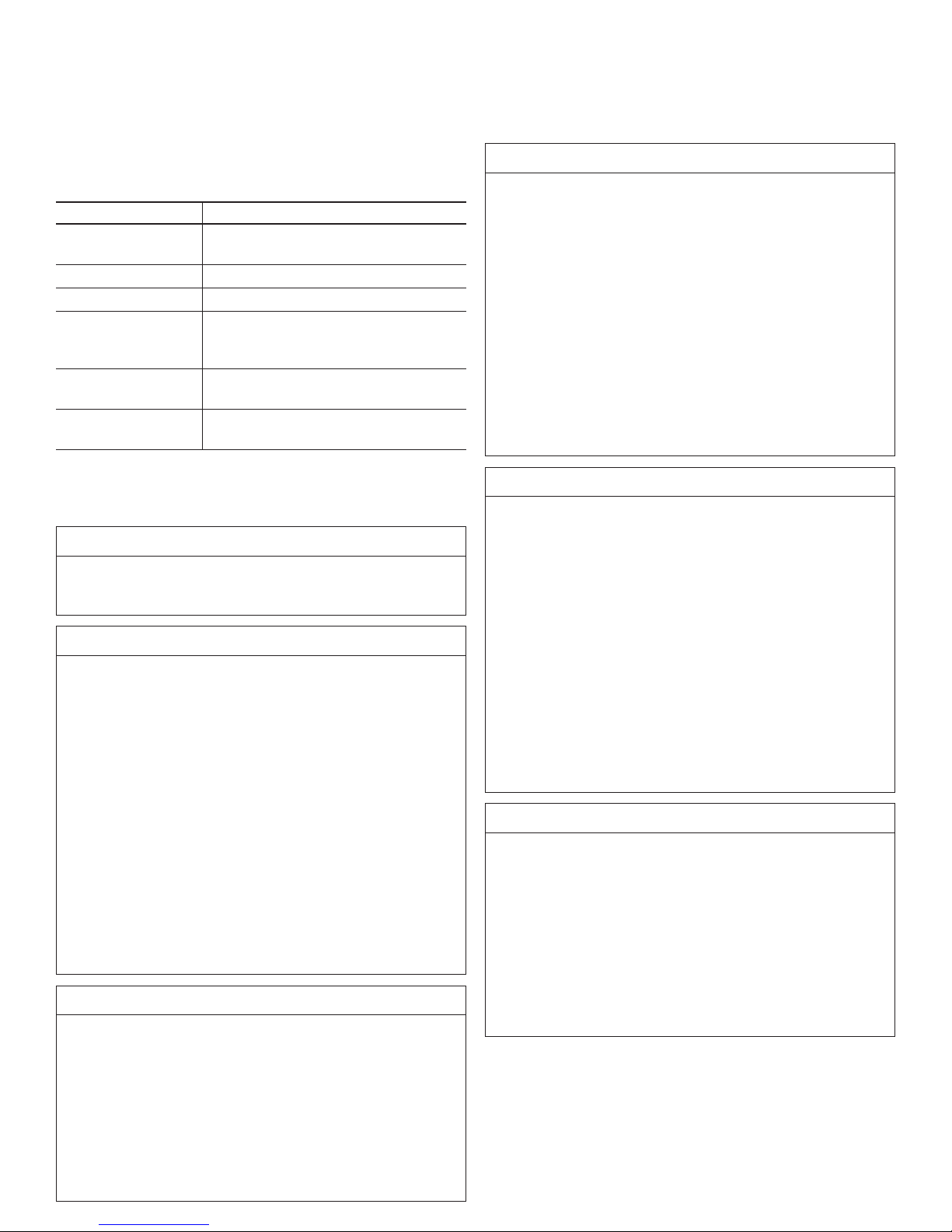
2 SPECIFICATIONS
2.1 Radio Module Specications
Table 3 – Radio Module Specications
Item Specication
Radio module Honeywell RFPCBa
Wireless standard
Data rate 250 kbps
Operating frequency
Module transmit
power (max.)
Receive sensitivity
(typ.)
IEEE Standard: 802.15.4; 2.4 GHz
global, license-free bands
ISM 2.4 GHz, global, license-free band
Country code A: 14 dBm max;
Country code B: 8 dBm max
98 dBm
m WARNING
The WBX must be installed in accordance with the
requirements specified in this document in order to
comply with the specific Country Communication Agency
requirements (i.e., FCC, IC, ETSI, ACMA)
2.2 Electrical Specications
Table 4 – Electrical Specications
Item Specication
Battery 3.6 Vdc Lithium Thionyl Chloride; AA size, Qty: 2
Manufacturer: Honeywell, WBT7;
Xeno Energy, P/N XL060F; Tadiran, P/N TL
5903/S; Bipower, P/N: ER14505H
CAUTION
Do not mount or remove the antenna when batteries are
present in WBX product as damage could occur to the WBX
electronics and/or ignite the surrounding hazardous atmosphere.
2.3 EMC Specications
The latest applicable EMC Standards are as follows:
• EN 300 328, V1.8.1
• EN 613261 (2013)
• EN 301 4891, V1.9.2
• EN 301 48917, V2.2.1
50096377
Specific Conditions of Safe Use:
• Aluminum enclosure – Care should be taken to minimize the
risk of ignition due to impact or friction.
• Potential electrostatic discharge – Clean product only with a
damp cloth.
• The metal “S-shaped” clamp which provides securement of
the cover to the enclosure housing shall always be secured in
place, when product is in use.
• Do not open when an explosive atmosphere may be present.
• Do not replace the battery when an explosive atmosphere is
present.
• Use only Honeywell battery P/N: WBT7; approved battery
manufacturers: Xeno Energy – XL060F; Tadiran – TL
5903/S; or BiPower ER14505H batteries.
, ATTENTION
IEC 600790:200710 and IEC 6007911:2006 were
applied to the integral component fuse, Part No.
0259.125TX913 manufactured by Littelfuse. There are no
significant safety related changes between these editions
and the later editions of the standards noted under the
“Standards” section of this document.
, ATTENTION
The antenna cables should not be modified (i.e. cut short
and/or re-terminated) as it may affect Communication
Agency approval. Approved antennas (refer to Section 6.2)
are the only antennas allowed for use with the WBX.
2.4 Functional Specications
Table 5 – Functional Specications
Item Specication
High temperature endurance
Low temperature endurance
Electrical/mechanical life
70 °C; 10,000 cycles; 15 cpm
40 °C; 10,000 cycles; 15 cpm
25 °C; 1 million operating
cycles
, ATTENTION
The WBX cannot be used in a portable application. It must
be used in a fixed location.
4 sensing.honeywell.com
Page 5
Installation Instructions for the
ISSUE 3
Wireless Hazardous Area Limit Switches, WBX Series
2.5 Environmental Specications
Table 6 – Environmental Specications
Item Specication
Operating
temperature
Storage temperature 40 °C to 70 °C [40 °F to 158 °F]
Operating humidity 0 %RH to 100 %RH
Vibration
Shock
Sealing
40 °C to 70 °C [40 °F to 158 °F]
IEC 6006826: 10 Hz to 58 Hz -
0,35 mm peak-to-peak,
58 Hz to 500 Hz, 10 g
IEC 60068227; half sine,
50 g, 6 mS
Type 1, 3, 4, 13;
IP67 (self-declared)
3 OUTDOOR INSTALLATION
WARNINGS
m WARNING
LIVES MAY BE AT RISK!
Carefully observe these instructions and any special
instructions included with the equipment being installed.
m WARNING
CONTACTING POWER LINES COULD BE FATAL
Look over the site before beginning any installation and
anticipate possible hazards, especially these:
• Make sure no power lines are near where possible contact can be made. Antennas, masts, towers, guy wires, or
cables may lean or fall and contact these lines. People
may be injured or killed if they are touching or holding
any part of equipment when it contacts electric lines.
Make sure there is NO possibility that equipment or
personnel can come in contact directly or indirectly with
power lines.
• Assume all overhead lines are power lines.
• The horizontal distance from a tower, mast, or antenna to
the nearest power line should be at least twice the total
length of the mast/antenna combination. This will ensure
that the mast will not contact power if it falls during
either installation or later.
m WARNING
If a person comes in contact with electrical power, and
cannot move
DO NOT TOUCH THAT PERSON OR RISK
ELECTROCUTION.
• Use a non-conductive dry board, stick, or rope to push,
pull, or drag them so they no longer are in contact with
electrical power.
• Once they are no longer contacting electrical power,
administer CPR if certified, and make sure emergency
medical aid has been requested.
m WARNING
TO AVOID FALLING, USE SAFE PROCEDURES
WHEN WORKING AT HEIGHTS ABOVE GROUND
• Select equipment locations that will allow safe, simple
equipment installation
• Don’t work alone. A friend or co-worker can save a life if
an accident happens.
• Use approved, non-conducting ladders and other safety
equipment. Make sure all equipment is in good repair.
• If a tower or mast begins falling, don’t attempt to catch it.
Stand back and let it fall.
• If anything such as a wire or mast does come in contact
with a power line, DON’T TOUCH IT OR ATTEMPT TO
MOVE IT.
• Instead, save a life by calling the power company.
• Don’t attempt to erect antennas or towers on windy days.
m WARNING
MAKE SURE ALL TOWERS AND MASTS ARE
SECURELY GROUNDED, AND ELECTRICAL
CABLES CONNECTED TO ANTENNAS HAVE
LIGHTNING ARRESTORS.
This will help prevent fire damage or human injury in
case of lightning, static build up, or short circuit within
equipment connected to antenna.
• The base of the antenna mast or tower must be connected directly to the building protective ground or to one-ormore approved grounding rods, using 1 AWG ground wire
and corrosion-resistant connectors.
• Refer to the National Electrical Code for grounding details.
• Lightning arrestors for antenna feed coaxial cables determined as ‘Simple Apparatus’ is allowed and approved
for use.
, ATTENTION
When the WBX switch is being installed or operating in a
hazardous environment, the end customer/user should
issue a work permit to a trained professional installer prior
to any work performed on the WBX Series limit switch. This
includes the following actions:
• Installation and/or operation of the WBX Series limit
switch
• Installation and/or adjustment of a remote antenna for
the WBX Series limit switch
• Maintenance on the WBX Series limit switch, including
battery replacement, pairing, purging, etc.
50096377
Sensing and Internet of Things 5
Page 6

Installation Instructions for the
ISSUE 3
Wireless Hazardous Area Limit Switches, WBX Series
4 CERTIFICATIONS AND SAFETY
APPROVALS
4.1 Safety Approvals
Table 7 – Hazardous Location Standards and Certications
cULus Listing ATEX Certication IEC Ex Certication
Standards: UL913 8th edition;
CAN/CSAC22.2 NO. 15792 (R2012);
UL 600790 edition 6.0;
UL 6007911 edition 6.0;
CSA C22.2 No. 6007911: 14 edition 2.0;
CSA C22.2 No. 600790: 11 edition 2.0
Class I, Div 1, Groups A, B, C, D T4
Class II, Div 1, Groups E, F, G
Class I, Zone 1 AEx ia IIC T4 Ga
Class I, Zone 1 Ex ia IIC T4 Ga
Class II, Zone 21 AEx ia IIIC T135°C Da
Class I, Zone 0 AEx ia IIC T4 Ga
Class I, Zone 0 Ex ia IIC T4 Ga
Class II, Zone 20 AEx ia IIIC T135°C Da
Tambient 40°C to 70°C
Standards: EN 600790: 2012 +
A11:2013;
EN 6007911: 2012;
EN 6007926:2007
Zone 1 Ex ia IIC T4 Ga
Zone 21 Ex ia IIIC T135°C Da
Zone 0 Ex ia IIC T4 Ga
Zone 20 Ex ia IIIC T135°C Da
Standards: IEC 600790 edition 6.0;
IEC 6007911 edition 6.0;
IEC 6007926 edition 2.0
Zone 1 Ex ia IIC T4 Ga
Zone 21 Ex ia IIIC T135°C Da
Zone 0 Ex ia IIC T4 Ga
Zone 20 Ex ia IIIC T135°C Da
50096377
2813
II 1 G
II 1 D
4.2 RF Certication
Table 8 – Communication agency approvals and standards
Approval/Item Ratings/Description
FCC Part 15.247 and 15.209
Communication
agency approvals
and standards
Enclosure type
Hazardous location approvals
14
dBm
8 dBm ETSI, CE mark
Type 1, 3, 4, 13
IP67 (self-declared)
cULus, ATEX, IEC Ex
FCC ID: XJLWBX001
IC ID: 9832AWBX001IC
Industry Canada RSS 210
Issue 8
ACMA, CTick mark
6 sensing.honeywell.com
Page 7

Installation Instructions for the
Remote
Zones 0,
Uo = 5.0
Io = 757 mA
Po = 0.946
Co = 23.48
Lo = 4.487
Remote
Zones 0,
Uo = 5.0
Io = 757 mA
Po = 0.946
Co = 23.48
Lo = 4.487
ISSUE 3
Wireless Hazardous Area Limit Switches, WBX Series
5 DIAGRAMS
5.1 Connection Diagrams for Remote
Antenna Conguration
Figure 1 – WBX Connected to Remote Antenna2 Directly
Antenna
WBX
Limit
Switch
20/1, 21, IIC, IIIC, Ga, Da
V
W
µF
µH
Figure 2 – WBX Connected to Remote Antenna2 Via
Lightning Arrestor
WBX
Limit
Switch
RF Cable B
RF Cable A or B
Class I, II, Div. 1,
Groups A, B, C, D, E, F, G
Voc = 5.0 V
Isc = 757 mA
Po = 0.946 W
Ca = 23.48 µF
La = 4.487 µH
Lighting
Arrestor
Antenna
RF Cable
A or B
6 REMOTE ANTENNAS
6.1 Intrinsically Safe Device Entity
Parameters for Remote Antenna Cables
Table 9 – I Intrinsically Safe Device Entity Parameters
for Remote Antenna Cables
RF Cable A
WCA200RN
PRSP002
WCA200RN
PRSP010
RF Cable B
WCA200RNJR
SP002
WCA200RNJR
SP005
WCA200RNJR
SP010
WCA200RNJR
SP015
WCA200RNJR
SP020
Length
0,61 m
[2 ft]
3,05 m
[10 ft]
0,61 m
[2 ft]
1,52 m
[5 ft]
3,05 m
[10 ft]
4,57 m
[15 ft]
6,1 m
[20 ft]
50096377
Loss (dB)
0.34 49 pF 0.12 mH
1.69 245 pF 0.61 mH
0.34 49 pF 0.12 mH
0.85 122 pF 0.3 mH
1.69 245 pF 0.61 mH
2.54 367 pF 0.92 mH
3.38 490 pF 1.2 mH
Total
Capacitance
Total
Inductance
20/1, 21, IIC, IIIC, Ga, Da
V
W
µF
µH
NOTES:
(1) Only lightning surge arrestors determined to be
simple apparatus may be installed.
(2) Refer to Tables 10 and 11 in following page that cap-
tures the approved antenna to be used with the WBX
product as remote connection.
Class I, II, Div. 1,
Groups A, B, C, D, E, F, G
Voc = 5.0 V
Isc = 757 mA
Po = 0.946 W
Ca = 23.48 µF
La = 4.487 µH
Sensing and Internet of Things 7
Page 8

Installation Instructions for the
ISSUE 3
Wireless Hazardous Area Limit Switches, WBX Series
6.2 Approved Antennas
Table 10 – Antenna Options for United States, Canada, and Australia
ANTENNAS FOR USE IN UNITED STATES, CANADA, AND AUSTRALIA
(Note: all columns are independent of each other)
Antenna Type Code
(antenna provided with
product)
00 WAN03RSP WAN04RSP WAN03RSP WAN06RNJ
12 WAN09RSP WAN05RSP WAN04RSP
14 WAN10RSP WAN08RSP WAN05RSP
Remote Mount Antennas (allowed for use)
WAN08RSP
WAN09RSP
WAN10RSP
Antenna Accessory: Must be ordered separately
Magnetic Remote
Mount Assemblies/
Antennas
WAMM100RSP005
WAMM100RSP010
(allowed for use)
Extension Cable Assemblies/Antennas for
Remote Mount
WCA200RSJRSP002
WCA200RSJRSP005
WCA200RSJRSP010
WCA200RSJRSP015
WCA200RSJRSP020
(allowed for use)
50096377
Extension Cable Assemblies/Antennas for
Remote Mount
WCA200RNPRSP002
WCA200RNPRSP010
(allowed for use)
WAN11RSP
Note:
(1) Cable with a RPSMA plug that connects directly to the WBX RPSMA jack is used for Remote Antenna (exception, WAN06RNJ
which uses N-type jack)
(2) Industry Canada Compliance Statement: This device has been designed to operate with the antenna types listed in this docu-
ment, and having a maximum gain of 9 dBi. Antenna types not included in this list or having a gain greater than 9 dBi are
strictly prohibited for use with this device. The required antenna impedance is 50 Ohm.
Table 18. Antenna Options for All Other Approved Countries
ANTENNAS FOR USE IN ALL OTHER APPROVED COUNTRIES
(Note: all columns are independent of each other)
Antenna Type Code
(antenna provided with
product)
00 WAN03RSP WAN08RSP WAN04RSP WAN03RSP
12 WAN09RSP WAN08RSP WAN08RSP
14 WAN10RSP WAN09RSP
Remote Mount Antennas (allowed for use)
Antenna Accessory: Must be ordered separately
Magnetic Remote
Mount Assemblies/
Antennas
WAMM100RSP005
(allowed for use)
Magnetic Remote
Mount Assemblies/
Antennas
WAMM100RSP010
(allowed for use)
WAN10RSP
Extension Cable Assemblies/Antennas for
Remote Mount
WCA200RSJRSP002
WCA200RSJRSP005
WCA200RSJRSP010
WCA200RSJRSP015
WCA200RSJRSP020
(allowed for use)
WAN11RSP
Remote mount: Remote mount antenna uses a cable with an RPSMA plug that connects directly to the WBX RPSMA jack (exception, WAN06RNJ, which uses a cable with an RPN plug on one end and an RPSMA plug on the other end.)
8 sensing.honeywell.com
Page 9

Installation Instructions for the
ISSUE 3
Wireless Hazardous Area Limit Switches, WBX Series
7 BATTERIES
7.1 Battery Replacement
When to replace
• Battery is dead or low. The Wireless Receiver will give a
visual indication of the dead or low battery condition.
Upon this indication, proceed with replacing the battery in the WBX as per below.
Tools required
• Slotted or Phillips screwdriver
m WARNING
RISK OF DEATH OR SERIOUS INJURY
FROM EXPLOSION OR FIRE
Connection and disconnection of the batteries should only
be performed in a non-hazardous area. The batteries used
in this device may present a risk of fire or chemical burn if
mistreated. Do not recharge, disassemble, heat above 100°C
[212°F], or incinerate.
Failure to comply with these instructions could result in
death or serious injury.
m WARNING
RISK OF DEATH OR SERIOUS INJURY
FROM EXPLOSION OR FIRE
If the WBX is to be returned to Honeywell for any reason,
the battery MUST be removed prior to shipping. Dispose of
used batteries promptly per local regulations or the battery
manufacturer’s recommendations. Keep away from children.
Do not disassemble and do not dispose of in fire.
Failure to comply with these instructions could result in
death or serious injury.
m WARNING
RISK OF DEATH OR SERIOUS INJURY
FROM EXPLOSION OR FIRE
Both batteries must be the same model from the same
manufacturer. Mixing old and new batteries or different
manufacturers is not permitted.
Honeywell Battery P/N: WBT7 is available for ordering.
Use only the following 3.6 V lithium thionyl chloride (LiSOCl2) battery (non-rechargeable), size AA. No other
batteries are approved for use in the WBX Series. Always
replace both batteries at the same time.
• XENO Energy, part number: XL060F
• Tadiran, part number: TL5903/S
• BiPower, part number: ER14505H
, ATTENTION
When the WBX switch is being installed or operating in a
hazardous environment, the end customer/user should
issue a work permit to a trained professional installer prior
to any work performed on the WBX Series limit switch. This
includes the following actions:
• Installation and/or operation of the WBX Series limit
switch
• Installation and/or adjustment of a remote antenna for
the WBX Series limit switch
• Maintenance on the WBX Series limit switch, including
battery replacement, pairing, purging, etc.
50096377
m WARNING
When installing the battery, do not snag the battery terminal
on the clip or the battery may be damaged. Do not apply excessive force. Do not drop. Dropping the battery may cause
damage. If a battery is dropped, do not install the dropped
battery into the WBX. Dispose of dropped battery promptly
per local regulations or per the battery manufacturer’s recommendations.
Failure to comply with these instructions could result in
death or serious injury.
Sensing and Internet of Things 9
Page 10

Installation Instructions for the
ISSUE 3
Wireless Hazardous Area Limit Switches, WBX Series
Figure 3 – WBX Housing
Reference Figures 3 and 4.
Step Action
m
WARNING DO NOT DISASSEMBLE OR ASSEM
BLE WHEN AN EXPLOSIVE ATMOSPHERE IS
PRESENT
1 Using a #2 Philips screwdriver, unscrew the screw
holding the S-shaped clamp. Remove the screw and
S-shaped clamp that is holding down the housing
cover.
2 Remove the WBX housing cover by turning in
CCW direction as shown in Figure 3.
3 Remove the old batteries from the battery holder by
pulling on the battery extractors as shown.
4 Install each battery as follows to avoid damage to
the battery and holder:
• See label on battery PCBa defining the “+” and
“-” terminals to ensure battery is placed in
holder with correct polarity.
• Do not attempt to bend the battery’s holddown tabs forward.
• Insert the battery negative end first, at an
angle, and against the end of the tab. Push
down the battery into position gently. Ensure
the batteries are properly seated and making
contact.
IMPORTANT: If the ORANGE LED does not blink,
it is recommended to remove one of the batteries
and re-insert back again.
5 Repeat steps 3 and 4 for the other battery
6 Replace the cover and thread it on to housing by
turning in CW direction until tight.
7 Place the S-shaped clamp and tighten the screw
with a 1,5 Nm [13.3 in-lb] torque to firmly hold
down the housing cover.
8 Dispose of used battery promptly per local regula-
tions or the battery manufacturer’s recommendations. Keep away from children. Do not disassemble.
Do not dispose of in fire.
Note: Each battery contains 0,7 gm of lithium metal. There may
be shipping restrictions depending upon the total amount of
lithium metal.
Figure 4 – WBX Battery and Insulator
50096377
3
2
10 sensing.honeywell.com
Page 11

Installation Instructions for the
ISSUE 3
Wireless Hazardous Area Limit Switches, WBX Series
8 DECLARATION OF CONFORMITY
8.1 European (CE) Declaration of Conformity (DoC)
8.1.1 European Declaration of Conformity Statements
Figure 5 – European Declaration of Conformity (DoC)
50096377
Sensing and Internet of Things 11
Page 12

Installation Instructions for the
Free Position
D.T.
Differential
Travel
Mounting Pads
52,1 mm
[2.05 in]
19,81 mm
[0.78 in]
62,61 mm
[2.47 in]
Ø 76,2 mm
[3.00 in]
85,73 mm
[3.38 in]
2X
5/16-18 UNC-2B .875
38,1 mm
[1.50 in]
73,18 mm
[2.88 in]
25,4 mm
[1.00 in]
49,15 mm
[1.94 in]
31,75 mm
[1.25 in]
145,5 mm
[5.73 in]
15,9 mm
[0.63 in]
145,6 mm
[5.73 in]
Operating Head Code “A”
Straight Antenna
Operating Head Code “A”
90° Antenna
Total Tr avel
T.T.
Overtravel
O.T.
Pretravel
P. T.
R.T.
R.T. = Release Tr avel
R.T.
218,3 mm
[8.6 in]
2X Ø5,16 mm
[0.203 in]
mounting
hole
ISSUE 3
Wireless Hazardous Area Limit Switches, WBX Series
Figure 6 – WBX Dimensions (Side Rotary)
50096377
MECHANICAL OPERATING SPECIFICATIONS
for Side Rotary Actuators
Table 12 – Operating Specifications (Mechanical)*
Characteristic Operating Head Code “A” Momentary
Pretravel 17.5° max.
Overtravel 60° min.
Differential travel 7° max.
Total travel 85° ref
Operating torque 0,45 Nm [4 in-lb] max.
Full travel torque 0,68 Nm [6 in-lb] max.
* Operating point given in relation to actuator center
12 sensing.honeywell.com
Page 13

Installation Instructions for the
218,3 mm
52,10 mm
57,94 mm
15,9 mm
ISSUE 3
Wireless Hazardous Area Limit Switches, WBX Series
Figure 7 – WBX Dimensions (Pin Plunger)
[2.051 in]
[2.28 in]
operating
point
[8.6 in]
9,47 mm
[0.37 in]
2X Ø5,16 mm
[0.203 in]
mounting
hole
19,81 mm
[0.78 in]
41,28 mm
[1.63 in]
Ø 76,2 mm
[3.00 in]
85,73 mm
[3.38 in]
2X
5/16-18 UNC-2B .875
21,46 mm
[0.85 in]
Mounting Pads
50096377
145,5 mm
[5.73 in]
38,1 mm
[1.50 in]
73,18 mm
[2.88 in]
Operating Head Code “C”
Straight Antenna
MECHANICAL OPERATING SPECIFICATIONS
for Pin Plunger Actuators
Table 13 – Operating Specifications (Mechanical)*
Characteristic Operating Head Code “C” Top Plunger Plain
Pretravel 1,78 mm [0.07 in] max.
Overtravel 4,83 mm [0.19 in] min.
Differential travel 0,51 mm [0.02 in] max.
Operating force 20,02 N [4.5 lb] max.
Operating point 57,94 mm ± 0,50 mm [2.281 in ±0.02 in]
Full overtravel force 40 N [9 lb] max.
* Operating point given in relation to top mounting hole
25,4 mm
[1.00 in]
145,6 mm
[5.73 in]
Operating Head Code “C”
90° Antenna
Point
Differential
Travel
Release
Point
Pre
Travel
Full
Travel
Over
Travel
Operating
[0.63 in]
Sensing and Internet of Things 13
Page 14

Installation Instructions for the
155,5 mm
19,81 mm
ISSUE 3
Wireless Hazardous Area Limit Switches, WBX Series
Figure 8 – WBX Dimensions (Wobble)
[6.12 in]
38,99 mm
[1.54 in]
Ø 6,35 mm
[0.25 in]
[0.78 in]
Ø 76,2 mm
[3.00 in]
85,73 mm
[3.38 in]
21,46 mm
[0.85 in]
Mounting Pads
50096377
Pretravel
25,4 mm
[1.0 in]
145,5 mm
[5.73 in]
218,3 mm
[8.6 in]
2X Ø5,16 mm
[0.203 in]
mounting
hole
2X
5/16-18 UNC-2B .875
38,1 mm
[1.50 in]
Operating Head Code “J”
Straight Antenna
MECHANICAL OPERATING SPECIFICATIONS
for Wobble Stick Actuators
Table 14 – Operating Specifications (Mechanical)*
Characteristic Operating Head Code “J” Wobble Stick
Pretravel 25,4 mm [1.0 in] approx. radius
Operating force 2,8 N [10.0 oz] max.
* Operating point given in relation to wobble stick center
25,4 mm
[1.00 in]
73,18 mm
[2.88 in]
145,6 mm
[5.73 in]
Operating Head Code “J”
90° Antenna
15,9 mm
[0.63 in]
14 sensing.honeywell.com
Page 15

Installation Instructions for the
ISSUE 3
Wireless Hazardous Area Limit Switches, WBX Series
For the latest WBX Series installation information, please see the
Installation and Technical Manual, as well as other documents at
the following website:
1. Go to sensing.honeywell.com/hazardousareaswitches.
2. Click on the Documentation tab at the top of the page.
3. Click on the Related Product Information.
Multiple language versions of installation instructions and
other documents are available on Honeywell’s website. To access:
1. Go to sensing.honeywell.com/hazardousareaswitches
2. Select the product’s instructions from the installation instruction
section.
Installationsanweisungen und andere Dokumente stehen in
mehreren Sprachen auf der HoneywellWebsite zur Verfügung.
So greifen Sie darauf zu:
1. Gehen Sie auf die Webseite
sensing.honeywell.de/hazardousareaswitches
2. Wählen Sie im Bereich “Installationsanweisungen” die zum
entsprechenden Produkt gehörenden Anweisungen aus.
Versiones de las instrucciones de instalación y otros documentos se encuentran disponibles en el sitio de internet de Honeywell en múltiples idiomas. Para acceder:
1. Vaya a sensing.honeywell.com/hazardousareaswitches
2. Seleccione las instrucciones del producto en la sección de in-
struccions de instalación.
Les instructions d’installation et d’autres documents sont disponibles dans plusieurs langues sur le site Web d’Honeywell.
Procédure d’accès :
1. Accédez à la page sensing.honeywell.com/hazardousareaswitches
2. Sélectionnez les instructions relatives au produit qui vous intéresse dans la section « Installation Instructions
Sul sito Web di Honeywell sono disponibili istruzioni per
l’installazione in più lingue e altra documentazione. Per accedere:
1. Andare a sensing.honeywell.com/hazardousareaswitches
2. Selezionare le istruzioni per il prodotto nella sezione istruzioni
per l’installazione.
As versões em diversos idiomas das instruções de instalação
e outros documentos estão disponíveis no site da Honeywell.
Para acessar:
1. Vá para sensing.honeywell.com/hazardousareaswitches
2. Selecione as instruções do produto na seção de instruções de
instalação.
多语种安装指南和其他文档均可从霍尼韦尔的网站上获取。访问网
站:
1.前往 sensing.honeywell.com/hazardousareaswitches
2.从安装指南部分选择具体的产品指南。
50096377
Sensing and Internet of Things 15
Page 16

Installation Instructions for the
ISSUE 3
Wireless Hazardous Area Limit Switches, WBX Series
WARRANTY/REMEDY
Honeywell warrants goods of its manufacture as being free
of defective materials and faulty workmanship during the
applicable warranty period. Honeywell’s standard product
warranty applies unless agreed to otherwise by Honeywell
in writing; please refer to your order acknowledgement or
consult your local sales office for specific warranty details.
If warranted goods are returned to Honeywell during the
period of coverage, Honeywell will repair or replace, at its
option, without charge those items that Honeywell, in its sole
discretion, finds defective. The foregoing is buyer’s sole
remedy and is in lieu of all other warranties, expressed or
implied, including those of merchantability and fitness for a
particular purpose. In no event shall Honeywell be liable for
consequential, special, or indirect damages.
While Honeywell may provide application assistance personally,
through our literature and the Honeywell web site, it is buyer’s
sole responsibility to determine the suitability of the product in
the application.
SALES AND SERVICE
Honeywell serves its customers through a worldwide network of
sales offices, representatives and distributors. For application
assistance, current specifications, pricing or name of the nearest Authorized Distributor, contact your local sales office or:
E-mail: info.sc@honeywell.com
Internet: sensing.honeywell.com
Phone and Fax:
Asia Pacific +65 63552828
+65 64453033 Fax
Europe +44 1698 481481
+44 1698 481676 Fax
Latin America +13058058188
+13058838257 Fax
USA/Canada +18005376945
+18152356847
+18152356545 Fax
50096377
Specifications may change without notice. The information we
supply is believed to be accurate and reliable as of this writing.
However, Honeywell assumes no responsibility for its use.
Honeywell Sensing and Control
a division of Honeywell International, Inc.
11 West Spring Street
Freeport, IL 61032
Honeywell Sensing and Internet of Things
9680 Old Bailes Road
Fort Mill, SC 29707
honeywell.com
500963773EN IL50 GLOPrinted in USA.
March 2019
© 2019 Honeywell International Inc. All rights reserved.
 Loading...