

Page 1
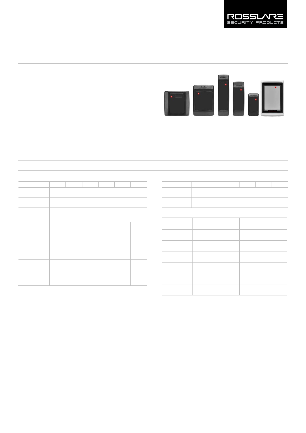
AY-x20 Family
Multi-format Proximity Readers
Installation Manual
1. Introduction
The AY-x20 is a family of RFID proximity card readers to be installed for
use with access control systems. The AY-x20 family reads the proximity
card and transmits its data to the access control system, using common
multi-format Wiegand outputs.
1.1 Key Features
Selectable Wiegand 26-Bit, Clock & Data
Reads 26-Bit EM or Rosslare format cards
Waterproof
Green LED control line
Red LED control line
Buzzer control line
Hold control line
Optical tamper sensor
Tamper output line
UV-protected polycarbonate housing
2. Technical Specifications
2.1 Electrical Characteristics
Specification AY-M20 AY-J20 AY-H20 AY-L20 AY-K20 AY-Q20
Power Supply
Type
Operating
Voltage Range*
Absolute
Maximum (nonoperating)
Current @ 12V
Read Range**
LED Control
Input
Tamper Output
Maximum Cable
Distance to
Controller
RF Modulation
Bit Rate
* All input voltages should be limited to 1 A maximum. For VAC, the voltage
range is peak-to-peak.
** Measured using a Rosslare proximity card or equivalent. Range also depends
on electrical environment and proximity to metal.
Open collector, active low, max. sink current 16 mA
Linear type (recommended)
5–16 VDC
18 VDC
Standby: 85 mA
Maximum: 100 mA
10 cm
(3.9 in.)
Dry Contact, N.O.
150 m (500 ft)
ASK, 125 KHz
106 KHz
8 cm
(3.2 in.)
(1.6 in.)
4 cm
Figure 1: AY-x20 Family
AY-M20 AY-H20
AY-L20
AY-J20
AY-K20
AY-Q20
2.2 7BEnvironmental Characteristics
Specification AY-M20 AY-J20 AY-H20 AY-L20 AY-K20 AY-Q20
Operating
Temp. Range
Operating
Humidity Range
-31°C to 63°C (-25°F to 145°F)
0 to 95% (non-condensing)
2.3 8BPhysical Characteristics
Model Dimensions
(H x W x D)
AY-M20
AY-J20
AY-H20
AY-L20
AY-K20
AY-Q20
88.9 x 88.9 x 15 mm
(3.5 x 3.5 x 0.6 in.)
120.0 x 42.0 x 14 mm
(4.7 x 1.7 x 0.6 in.)
109.9 x 74.9 x 15 mm
(4.3 x 3.0 x 0.6 in.)
144.9 x 42.9 x 20 mm
(5.7 x 1.7 x 0.8 in.)
79.9 x 39.9 x 12.8 mm
(3.2 x 1.6 x 0.5 in.)
120 x 76 x 20 mm
(4.7 x 3.0 x 0.8 in.)
Weight
109 g
(3.9 oz.)
88.5 g
(3.1 oz.)
100 g
(3.5 oz)
116 g
(4.1 oz)
70.5 g
(2.5 oz)
480 g
(17.0 oz)
1
Page 2
coded according the
3. Installation
3.1 Installation Kit
The installation kit consists of the following items to be used during
the installation procedure:
One mounting template
Two pan head screws and wall plugs
One L-shaped security screw tool
One security screw
3.2 Mounting the AY-x20 Reader
Before mounting, you should determine the best location for the
reader.
To mount the reader:
1. Peel off the back of the self-adhesive mounting label template and
place it at the required mounting location.
2. Using the template as a guide, drill two holes (sizes indicated on
the template) used for mounting the reader onto the surface.
3. Insert a suitable wall plug into each hole.
4. Drill a 10-mm (7/16”) hole for the cable. If mounting on metal,
place a grommet or electrical tape around the edge of the hole.
5. Wire the reader to the controller as described in Section 4. A linear
type power supply is recommended.
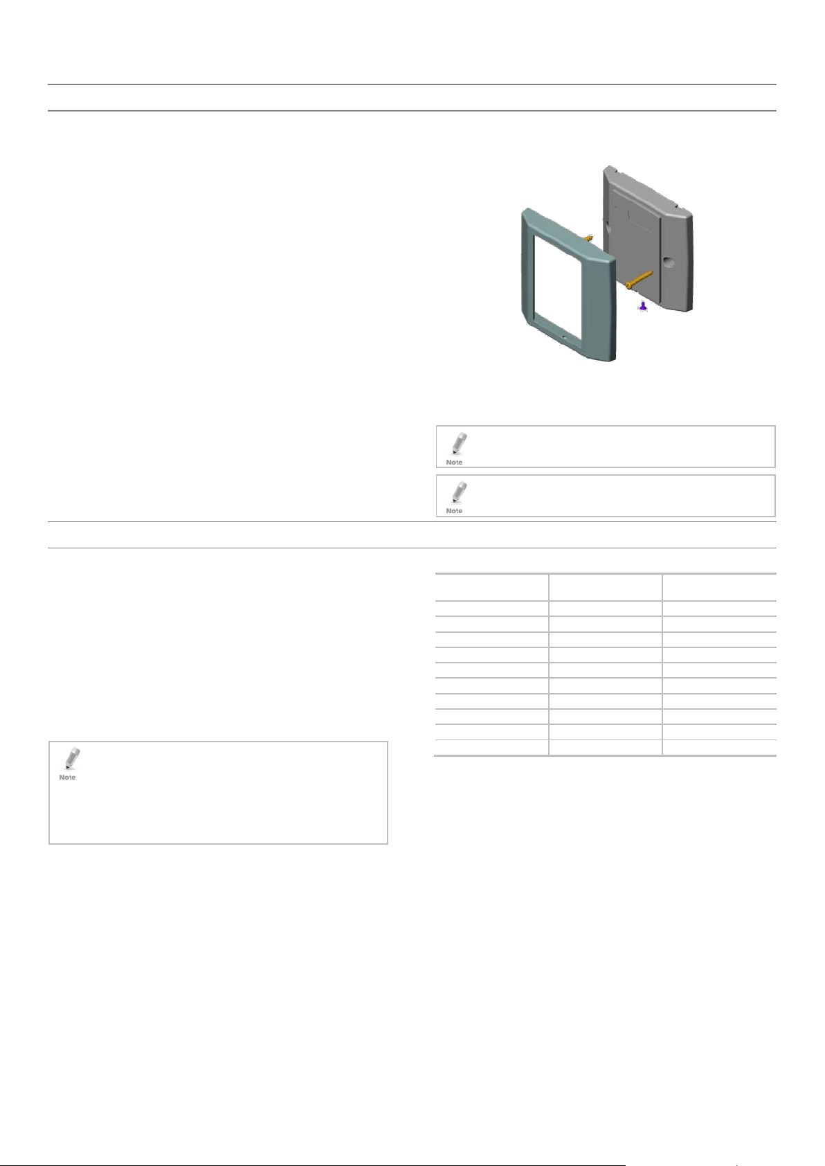
6. Remove the reader's snap-off front cover to reveal the two screw
holes (see Figure 2 ).
Figure 2: Removing the Top Cover
7. Align the two holes of the reader with those drilled in the wall and
firmly attach the reader to the wall with two screws, whose size is
indicated on the template.
8. Relocate the front cover onto the reader.
The reader can also be mounted using strong epoxy glue. After
application, the reader should be firmly held in place until the
glue dries.
Card readers are to be used with control panels whose power
supply is UL Listed Class 2 or equivalent.
4. Wiring
The AY-x20 is supplied with a 10-conductor 18” pigtail.
To connect the reader to the controller:
1. Prepare the reader cable by cutting its jacket back about 3 cm
(1¼") and strip the insulation from the wires about 1.2 cm (½").
2. Prepare the controller cable by cutting its jacket back 3 cm (1¼")
and strip the insulation from the wires about 1.2 cm (½").
3. Splice the reader’s pigtail wires to the corresponding controller
wires (as indicated in Table 1) and cover each joint with insulating
tape.
4. If the tamper output is being utilized, connect the purple wire to
the correct input on the controller.
5. Trim and cover all unused conductors.
• The individual wires from the reader are color-
Wiegand standard.
• When using a separate power supply for the reader, this supply
and that of the controller must have a common ground.
• The reader’s cable shield wire should be preferably attached to an
earth ground, or a signal ground connection at the panel, or
power supply end of the cable. This configuration is best for
shielding the reader cable from external interference.
Table 1: Wiring
Wire Color Wiegand 26-Bit Output
Mode
Red +DC +DC
Black Ground Ground
Green Data 0 Data
White Data 1 Clock
Orange Green LED Green LED
Brown Red LED Red LED
Yellow Buzzer Buzzer
Blue Hold Hold
Purple Tamper Tamper
Grey Open Input Connected to GND
Clock & Data Output
Mode
2
Page 3

5. Operation Instructions
5.1 Testing
Once the reader is wired to a power supply and to the controller, you
should test the reader.
To test the reader:
1. Power up the reader.
The LED and beeper activate one time. This indicates that the
reader is working properly.
2. Present the appropriate type of proximity card to the reader.
The LED momentarily flashes green and a short beep is emitted
indicating that the card was read properly by the reader.
After the card data is processed by the controller, the controller
can then turn the LED green. Refer to the controller description of
the LED operation if the reader LED is controlled by the controller.
5.2 Output Selection
For Wiegand 26-bit operation, the grey wire should be held not
connected.
For Clock & Data operation, the grey wire should be connected to
the ground
5.3 LED Control
If the LED control wires (orange and brown) are not used (open), the
reader LED remains red continuously, and flashes green momentarily
when successfully reading a card.
The bi-color LED color can be controlled using the orange and brown
wires.
When the orange wire is grounded, the LED is green
When the brown wire is grounded, the LED is red
When both the brown and orange wires are grounded, the LED is
amber.
5.4 Buzzer Control
If the buzzer control wire (yellow) is not used (open), the buzzer beeps
only when a card is read successfully. The buzzer can also be controlled
using the yellow wire. When the yellow wire is grounded, the buzzer
sounds.
5.5 Hold Control
The reading of cards can be disabled using the hold wire (blue). If the
blue wire is grounded, the reader ignores all cards placed in its field. If
the blue wire is open, the reader reads cards normally.
5.6 Tamper Output
This reader has an optical tamper sensor.
When the sensor detects light, the tamper output is grounded.
When the sensor does not detect light, the tamper output is held
to the high open collector.
3
Page 4

Declaration of Conformity
This device complies with Part 15 of the FCC Rules. Operation is
subject to the following two conditions:
This device may not cause harmful interference.
This device must accept any interference received, including
interference that may cause undesired operation.
Changes or modifications not expressly approved by the party
responsible for compliance could void the user's authority to
operate the equipment.
This equipment has been tested and found to comply with the limits
for a Class B digital device, pursuant to part 15 of the FCC Rules. These
limits are designed to provide reasonable protection against harmful
interference in a residential installation.
Limited Warranty
The full ROSSLARE Limited Warranty Statement is available in the Quick
Links section on the ROSSLARE website at
Rosslare considers any use of this product as agreement to the
Warranty Terms even if you do not review them.
www.rosslaresecurity.com.
Contact Information
United States and Canada
Rosslare Security Products, Inc.
Southlake, TX, USA
Toll Free: +1-866-632-1101
Local: +1-817-305-0006
Fax: +1-817-305-0069
support.na@rosslaresecurity.com
Europe
Rosslare Israel Ltd.
Rosh HaAyin, Israel
Tel: +972-3-938-6838
Fax: +972-3-938-6830
support.eu@rosslaresecurity.com
Latin America
Rosslare Latin America
Buenos Aires, Argentina
Tel: +54-11-4001-3104
support.la@rosslaresecurity.com
This equipment generates, uses, and can radiate radio frequency
energy and, if not installed and used in accordance with the
instructions, may cause harmful interference to radio communications.
However, there is no guarantee that interference will not occur in a
particular installation. If this equipment does cause harmful
interference to radio or television reception, which can be determined
by turning the equipment off and on, the user is encouraged to try to
correct the interference by one or more of the following measures:
Reorient or relocate the receiving antenna.
Increase the separation between the equipment and receiver.
Connect the equipment into an outlet on a circuit different from
that to which the receiver is connected.
Consult the dealer or an experienced radio/TV technician for help.
China
Rosslare Electronics (Shenzhen) Ltd.
Shenzhen, China
Tel: +86-755-8610-6842
Fax: +86-755-8610-6101
support.cn@rosslaresecurity.com
Asia Pacific, Middle East, Africa
Rosslare Enterprises Ltd.
Kowloon Bay, Hong Kong
Tel: +852-2795-5630
Fax: +852-2795-1508
support.apac@rosslaresecurity.com
India
Rosslare Electronics India Pvt Ltd.
Tel/Fax: +91-20-40147830
Mobile: +91-9975768824
sales.in@rosslaresecurity.com
www.rosslaresecurity.com
0706-0960030+04
4
 Loading...