

Honeywell VMC-03WENN1, VMC-01WENN1, VMC-04WENN1, VMC-00WENN1, VMC-02WENN1 Installation Manual
Page 1

Installation Manual
Tema-Voyager™ Multi
VMC-xx
1
Page 2

Document Release Issue Date
800-20652
1.0
H December 2017
Notice
This document contains Honeywell proprietary information. Information contained herein is to be
used solely for the purpose submitted, and no part of this document or its contents shall be
reproduced, published, or disclosed to a third par ty without the express permission of Honeywell
Europe.
This document and the data in it shall not be duplicated, used or disclosed to others for
procurement or manufacturing, except as authorized by and with the written permission of
Temaline, Inc. The information contained in this document or in the product itself is the exclusive
property and trade secrets of Temaline, Inc.
Copyright laws of the United States protect all information in this document or in the software
product itself.
While this information is presented in good faith and believed to be accurate, Honeyw ell disclaims
the implied warranties of merchantability and fitness for a purpose and makes no express
warranties except as may be stated in its written agreement with and for its customer.
In no event is Honeywell liable to anyone for any direct, special, or consequential damages.
The information and specifications in this document are subject to change without notice.
Trademarks
Tema-VoyagerTM is a trademark of Honeywell International Inc.
MIFARE® is a registered trademark of Philips Electronics N.V.
HID is a trademark or registered trademark of HID Global Corporation.
Any other trademarks that appear in this document are used only to the benefit of the trademark
owner, with no intention of trademark infringement.
Compliance
To obtain applicable EU compliance Declaration of Conformities for this product, please refer to
our website, https://extranet.honeywell.com
compliance of this product to any EU-specific requirements, please send email to
temaline.orders@honeywell.com
. For any additional information regarding the
Single contact point and Support
Manufacturer’s single point of contact:
Honeywell S.r.l.
Via Philips, 12
20052 Monza
ITALY
For technical assistance, call your nearest Honeywell office.
2
Page 3

TABLE OF CONTENTS
INTRODUCTION .......................................................................................................................................................... 9
Purpose of this manual ......................................................................................................................................... 9
Device overview .................................................................................................................................................... 9
System Architecture ............................................................................................................................................ 10
Device components ............................................................................................................................................. 11
Related documentation ....................................................................................................................................... 11
PREPARING FOR INSTALLATION .......................................................................................................................... 12
Contents of the box ............................................................................................................................................. 12
Multi device .................................................................................................................................................... 12
Device support kit .......................................................................................................................................... 12
Optional Boards (included into a separate box) ............................................................................................. 12
Spare Parts ......................................................................................................................................................... 13
Mounting tools ..................................................................................................................................................... 13
Calculation of the current provided by Multi ........................................................................................................ 13
Wires Characteristics .......................................................................................................................................... 15
Power supply wire .......................................................................................................................................... 15
Network wire .................................................................................................................................................. 15
Readers wires ................................................................................................................................................ 15
RS485 Data Cables (for OSDP reader connection) ................................................................................ 15
Wiegand reader cables ........................................................................................................................... 16
Input wires ..................................................................................................................................................... 16
Output cable .................................................................................................................................................. 16
MOUNTING THE DEVICE ......................................................................................................................................... 17
Wall mount .......................................................................................................................................................... 17
DIN rail mount ..................................................................................................................................................... 18
IP32 protection mount ......................................................................................................................................... 18
CONNECTING THE CABLES ................................................................................................................................... 20
Connecting the DC Power Supply ....................................................................................................................... 21
Connecting the network cable ............................................................................................................................. 22
Connecting the readers ....................................................................................................................................... 24
Reader in position 1 ....................................................................................................................................... 26
Reader in position 2 ....................................................................................................................................... 26
Reader in position 3 ....................................................................................................................................... 27
Reader in position 4 ....................................................................................................................................... 27
RS485 line length setting ............................................................................................................................... 28
Connecting Inputs ............................................................................................................................................... 29
Connecting Fixed Inputs ................................................................................................................................ 30
Fixed Input 1 ........................................................................................................................................... 30
Fixed Input 2 ........................................................................................................................................... 30
Fixed Input 3 ........................................................................................................................................... 31
Fixed Input 4 ........................................................................................................................................... 31
Connecting configurable Inpu t s ..................................................................................................................... 32
Configurable Input 1 ............................................................................................................................... 32
Configurable Input 2 ............................................................................................................................... 32
Configurable Input 3 ............................................................................................................................... 33
3
Page 4

Configurable Input 4 ............................................................................................................................... 33
Configurable Input 5 ............................................................................................................................... 34
Configurable Input 6 ............................................................................................................................... 34
Configurable Input 7 ............................................................................................................................... 35
Configurable Input 8 ............................................................................................................................... 35
Connecting Outputs ............................................................................................................................................ 36
Connecting Fixed Outputs ............................................................................................................................. 37
Fixed Output 1 ........................................................................................................................................ 37
Fixed Output 2 ........................................................................................................................................ 37
Fixed Output 3 ........................................................................................................................................ 38
Fixed Output 4 ........................................................................................................................................ 38
Connecting Configurable Outputs .................................................................................................................. 39
Configurable Output 1 ............................................................................................................................. 39
Configurable Output 2 ............................................................................................................................. 39
Configurable Output 3 ............................................................................................................................. 40
Configurable Output 4 ............................................................................................................................. 40
Configurable Output 5 ............................................................................................................................. 41
Configurable Output 6 ............................................................................................................................. 41
Configurable Output 7 ............................................................................................................................. 42
Configurable Output 8 ............................................................................................................................. 42
USING RELAYS PLUGS-IN (VMA-06, VMA-07) ....................................................................................................... 44
Mounting the plugs-in .......................................................................................................................................... 45
Setting up Plug-in jumper .................................................................................................................................... 47
Configuration of Multi to use VMA-06 and VMA-07 plugs-in ............................................................................... 48
Connecting Fixed Outputs (Plug-in in slot of position 1) ................................................................................ 49
Fixed Output 1 ........................................................................................................................................ 49
Fixed Output 2 ........................................................................................................................................ 49
Fixed Output 3 ........................................................................................................................................ 50
Fixed Output 4 ........................................................................................................................................ 50
Connecting Configurable Outputs (Plug-in in slot of position 2) ..................................................................... 51
Configurable Output 3 ............................................................................................................................. 51
Configurable Output 4 ............................................................................................................................. 51
Configurable Output 5 ............................................................................................................................. 52
Configurable Output 6 ............................................................................................................................. 52
Connecting Configurable Outputs (Plug-in in slot of position 3) ..................................................................... 53
Configurable Output 1 ............................................................................................................................. 53
Configurable Output 2 ............................................................................................................................. 53
Configurable Output 7 ............................................................................................................................. 54
Configurable Output 8 ............................................................................................................................. 54
Connection of the emergency input to VMA-07 ............................................................................................. 55
FINAL OPERATIONS ................................................................................................................................................ 56
Closing the device ............................................................................................................................................... 56
Commissioning tips ............................................................................................................................................. 56
Configuring the Voyager Multi ........................................................................................................................ 57
Factory default IP Address ..................................................................................................................... 57
Factory FW version ................................................................................................................................. 57
MULTI DEVICE ANATOMY ....................................................................................................................................... 58
Terminal Blocks and Jumpers ............................................................................................................................. 59
Terminal Blocks ............................................................................................................................................. 59
Jumpers ......................................................................................................................................................... 60
Switches and LEDs ............................................................................................................................................. 61
Switches ........................................................................................................................................................ 61
LED ................................................................................................................................................................ 62
Device Tampers .................................................................................................................................................. 63
Anti open tamper ........................................................................................................................................... 63
4
Page 5

External tampers connection ......................................................................................................................... 64
OPERATING INSTRUCTIONS & MAINTENANCE ................................................................................................... 65
Reset Multi device ............................................................................................................................................... 65
Switch off Multi device ......................................................................................................................................... 65
Multi application quick health chec k .................................................................................................................... 66
CONDITIONS RESULTING IN IMPAIRED OPERATION .......................................................................................... 67
PROTECTIVE FEATURES (WARNING OF BYPASSING) ....................................................................................... 68
TECHNICAL SPECIFICATIONS ................................................................................................................................ 69
REGULATIONS ......................................................................................................................................................... 71
CE Compliance ................................................................................................................................................... 71
“Access Control System for use in Security Applications” Compliance ............................................................... 71
FCC Notice.......................................................................................................................................................... 72
Canadian and United States UL Listed ............................................................................................................... 72
Australian CTick Conformity ................................................................................................................................ 73
RoHS compliance ............................................................................................................................................... 73
WEEE compliance .............................................................................................................................................. 73
China RoHS declaration ...................................................................................................................................... 73
Appendix 1 - Application switches ......................................................................................................................... 74
Appendix 2 – Meaning of graphical symbols used ............................................................................................... 75
5
Page 6

Warnings and Cautions
Before installat ion
Warning: Before installation, TURN OFF the external circuit breaker which supplies
power to the device.
Before connecting the device to the power supply, verify that the output voltage is within
specifications of the power supply. (See “Technical specifications” on page 37.)
Do not apply power to the device until after the installation has been completed.
The equipment can be damaged if this precaution is not observed.
Fire Safety and Liability Notice
Warning: Never connect card readers to any critical entry, exit door, barrier, elevator or
gate without providing an alternative exit in accordance with all the fire and life safety
codes pertinent to the installation.
These fire and safety codes vary from city to city and you must get approval from local
fire officials whenever using an electronic product to control a door or other barrier. Use
of egress buttons, for example, may be illegal in some cities. In most applications, single
action exit without prior knowledge of what to do is a life safety requirement. Always
make certain that any required approvals are obtained in writing.
DO NOT ACCEPT VERBAL APPROVALS SINCE THEY ARE NOT VALID.
Damage during shipment
Caution: IF ANY DAMAGE TO THE SHIPMENT IS NOTICED, A CLAIM MUST BE
FILED WITH THE COMMERCIAL CARRIER RESPONSIBLE FOR THE DAMAGE.
Electrostatic discharge
Caution: Electrostatic discharge (ESD) can damage integrated circuits and modules. To
prevent damage always follow these procedures.
Use static shield packaging and containers to transport all electronic components,
including completed reader assemblies.
Handle all ESD sensitive components at an approved static controlled workstation. These
workstations consist of a desk mat, floor mat and an ESD wrist strap. Workstations are
available from various vendors.
Note: This equipment generates, uses, and can radiate radio frequency energy and, if not
installed and used in accordance with the installation and user guides, may cause harmful
interference to radio communications. Operation of this equipment in a residential area is
likely to cause harmful interference in which case the user will be required to correct the
interference at his own expense.
Disclaimer – Product Liability; Mut ual Indemnification
If a Customer receives a claim that a Product or any component thereof has caused
personal injury or damage to the property of others, Customer shall immediately notify
Honeywell S.r.l. Italy in writing of all such claims. Honeywell S.r.l. Italy shall defend or
settle such claims and shall indemnify and hold Customer harmless for any costs or
damages including reasonable attorneys’ fees which Customer may be required to pay as a
result of the defective Product or the negligence of Honeywell S.r.l. Italy, its agents, or its
employees.
6
Page 7

Customer shall hold harmless and indemnify Honeywell S.r.l. Italy from and against all
claims, demands, losses and liability arising out of damage to property or injury to persons
occasioned by or in connection with the acts or omissions of Customer and its agents and
employees, and from and against all claims, demands, losses and liability for costs of fees,
including reasonable attorneys’ fees, in connection therewith.
Compliance
For any additional information regarding the compliance of this product to any EUspecific requirements, please send an e-mail to temaline.orders@honeywell.com.
Unpacking
Caution: If any damage to the shipment is noticed before unpacking, a claim must be filed
with the commercial carrier.
All containers should be opened and unpacked carefully in order to prevent damage to the
contents.
Follow these steps to unpack equipment in preparation for installation:
Open the container and remove the unit(s) and all packing material. Retain the container
and all the packing materials. They may be used again for reshipment of the equipment, if
needed.
Inspect the contents to see if anything is missing. If you notice any missing items, send an
e-mail to temaline.orders@honeywell.com.
Visually check the contents. If you see any damage, do the following:
If shipping has caused damage to the unit, file a claim with the commercial carrier.
If any other defect is apparent, call for a return authorization.
Shipping instructions
To ship equipment back to Temaline, contact the customer service department at
temaline.orders@honeywell.com before returning the equipment. When you call, please have
available:
A description of the problem or the reason you are returning the equipment.
Your original purchase order number, invoice number and if the unit is still under
warranty.
A new purchase order number if the unit is not under warranty.
From the customer service department, obtain the Return Merchandise Authorization
(RMA).
Show the RMA number on all packages shipped. Packages which are not marked with an
RMA number will be refused at the factory and returned to you COD.
Carefully pack the equipment for shipment. Use the original packing material whenever
possible
Limited warranty
All warranty work shall be handled through Customer who shall notify Temaline and
apply for a Return Merchandise Authorization (RMA) number prior to returning any
Product for service, repair, credit or exchange. Temaline warrants that its Products shall be
free from defects in materials and workmanship for a period of 18 months from the date of
shipment from the Temaline warehouse. Satisfaction of this warranty shall be limited to
repair or replacement of Products which are defective or defective under normal use.
7
Page 8

Temaline’s warranty shall not extend to any Product which, upon examination, is
determined to be defective as a result of misuse, improper storage, incorrect installation,
operation or maintenance, alteration, modification, accident or unusual deterioration of the
Product due to physical environments in excess of the limits set forth in Product manuals.
THERE ARE NO WARRANTIES WHICH EXTEND BEYOND THIS PROVISION.
THIS WARRANTY IS IN LIEU OF ALL OTHER WARRANTIES WHETHER
EXPRESS, IMPLIED OR STATUTORY, INCLUDING IMPLIED WARRANTIES OF
MERCHANTABILITY OR FITNESS FOR ANY PARTICULAR PURPOSE. NO
REPRESENTATION OR WARRANTY OF THE DISTRIBUTOR SHALL EXTEND
THE LIABILITY OR RESPONSIBILITY OF THE MANUFACTURER BEYOND THE
TERMS OF THIS PROVISION. IN NO EVENT SHALL TEMALINE BE LIABLE FOR
ANY RE-PROCUREMENT COSTS, LOSS OF PROFITS, LOSS OF USE,
INCIDENTAL, CONSEQUENTIAL OR SPECIAL DAMAGES TO ANY PERSON
RESULTING FROM THE USE OF TEMALINE’S PRODUCTS.
Confidentiality
All software, drawings, diagrams, specifications, catalogs, literature, manuals and other
materials furnished by Honeywell HSG –Temaline relating to the design, use and service
of the Products shall remain confidential and shall constitute the proprietary rights of
Honeywell HSG -Temaline and Customer agrees to treat such information as confidential.
Customer shall acquire no rights in the design of the Products or the related materials
except to use such information solely for the purpose of and only during the time it sells
the Products. Customer shall not copy the design of any of the Products or use or cause to
be used any Product design or related materials for its own benefit or for the benefit of any
other party. The covenants contained in this section shall remain effective throughout the
term of this Agreement and thereafter unless specifically waived by Honeywell HSG Temaline in writing.
8
Page 9

INTRODUCTION
Purpose of this manual
This manual details how to install the Tema-Voyager™ Multi (from
now on it will be simply called: Multi).
Details on operating instruction, plant maintenance and
troubleshooting are also provided.
Device overview
Multi acts as a controller in Temaline architecture.
Multi manages applications included: Access Contr ol ,
Time&Attendance, Canteen and light Intrusion detection.
It has the capability to manage up to 4 third party readers.
The readers can be connected to the device through standard
Wiegand lines or RS485 lines and OSDP protocol.
The usage of OSDP protocol with secure channel makes the solution
more secure in respect to the one using Wiegand connection.
Doors can be managed with reader on one side and REX button on
the other, or with readers on both sides of the door.
The actual number of the readers managed by your dev ic e is based
on the product you purchased (see: Contents of the box - Multi device).
Multi has on board dig i tal I/O use d for the m a nag em ent of the
Wiegand reader (buzzer, green/red led, reader tamper) and also 4
inputs (that can be set to be supervised or digital), 4 open drain
outputs and 8 I/O lines can be freel y configured as inputs or outputs.
These I/O can be used both for the manage m ent o f the doors and for
light Intrusion detection purpose.
Two different types of relays boards are available, as options, for the
Multi device. Each relay board can manage up to 4 outputs 24V @3A.
Up to 3 relay output boards can be connected to the Multi (See:
USING RELAYS PLUGS-IN (VMA -06, VMA-07))
9
Page 10
It is connected to the supervisor centre and with other peer devices via
Ethernet line (10Mb/100Mb/1Gb).
It can be supplied with an external 10-30 V DC power supply or using
POE or POE+
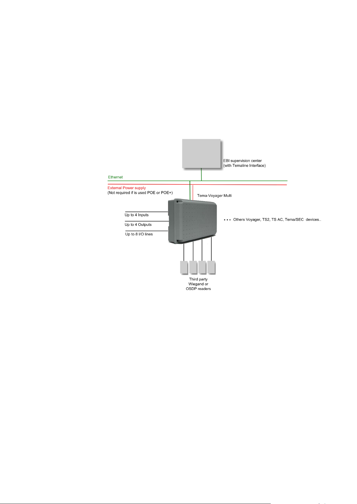
System Architecture
Figure 1 shows a typical system architecture in which Multi is inserted.
Figure 1 – Multi system architecture
The connections shown are:
• The Ethernet connection: it connects Honeywell Enterprise
Buildings Integrator™ (EBI) supervision center and in peer to
peer other Temaline peripheral devices.
• The external Power supply connection; not required if the Multi
device is supplied using POE or POE+.
• The Reader connections: to connect Multi with third party
readers (Wiegand connection and RS485/OSDP connection).
• Inputs/outputs connections
As part of the overall Temaline solution, Multi is fully compatible to
peer to peer communication with other Temaline peripheral devices
(TS-AC01, TS2, Tema/SEC, Tema ID, Tema-Voyager™ Compact).
10
Page 11
Device components
This chapter gives an overview of the components of MULTI device;
the intent is to provide the main terms used into the installation phase.
For a more deep understanding of the device please refer to the
chapter Multi Device Anatomy.
Related documentation
Document Content
EBI - Temaline Access Control
Configuration Guide
Tema-Voyager Multi - Web
interface Guide
Tema-Voyager Multi - Quick
Installation Guide
Voyager Multi - VMA06 VMA07 Quick installation Guide
Figure 2 - Multi components overview
Further information on the EBI T ema system ,
complete commissioning steps and system
configuration are inc luded in the CD which is
provided with EBI documentation package.
User manual of the MULTI Web Interface
used for commissioning and maintenance
operations.
It’s the quick guide f or the Mult i installation; it
is included into the device box.
It’s the quick guide for the VMA-06, VMA-07
plugs in installation; it is shipped together
with the devices box.
11
Page 12

PREPARING FOR INSTALLATION
Contents of the box
Before you begin, unpack the shipment and check the parts list
against the components in the shipment.
Your shipment contains:
Multi device
One of the following Multi devices:
Code Item
VMC-00WENN1 Tema-Voyager Multi-0, it is used for managem ent of onl y I/O,
no reader connection available..
VMC-01WENN1 Tema-Voyager Multi-1, it manages 1 reader and I/O
VMC-02WENN1 Tema-Voyager Multi-2, it manages up to 2 readers and I/O
VMC-03WENN1 Tema-Voyager Multi-3, it manages up to 3 readers and I/O
VMC-04WENN1 Tema-Voyager Multi-4, it manages up to 4 readers and I/O
Device support kit
Code Qty Item
P8160-5 4 Shunt Jumper, 2PINS, FEM, 2.54mm, 3.0A, -55C to
+105C
300-04883 12 Resistor: CARB. 392R 1/4W 1% THT LF (White)
300-04884 12 Resistor: METAL. 1K21, 1/4W 1% THT LF (Yellow)
300-07677 4 Resistor: CARB. 270R, 1%, 1/4W THT LF (Blue)
P460 12 Diodes 1N4004 or equivalent
700-04116 1 Lower seal rubber (to be u sed only when IP32 protection
is required)
700-04114 1 Upper seal rubber (t o be used only when IP32 protection
is required)
800-19900 1 Tema-Voyager Multi - Quick Installation Guide
Optional Boards (included into a separate box)
Code Item
VMA-06 Tema-Voyager Multi Relay Output board: provides 4 R elay Output,
dry contact NO/NC 24V-3A.
Up to 3 can be added to a Multi device.
12
Page 13

Spare Parts
VMA-07 Tema-Voyager Multi Emergency Relay Output board, provides:
4 Relay Output, dry contact NO/NC 24V-3A;
1 Input, dry contact, for emergency alarm, with separate power
supply.
Up to 1 can be added to a Multi device.
800-20479 Tema-Voyager Multi - VMA06, VMA07 - Quick Installation Guide
(only when optional boards are presen t)
It is possible to order the following spare parts for this device:
Spare part
code
VMS-RUB 700-04114
VMS-KIT 100-05961 Resistors and diodes kit. 1
Code Item Q.ty
Upper Seal Rubber
700-04116
Lowest Seal Rubber
Mounting tools
The following screwdrivers are required for the installation:
• 3mm slotted screwdriver
• T10 Torx screwdriv er
Calculation of the current provided by Multi
Multi device can be powered either with a 10V-30V DC
power supply, PoE or PoE+; each of these power sources can provide
a different amount of current used to power the Multi device itself,
outputs, readers and door locks directly supplied by the device.
Tema-Voyager Multi - Consumption Veri fier s pr eadsheet is been
available into EBI Global Support repository to help in calculate the
max number of outputs, readers and door lock s can be directly
connected to the device and to verify that their consumption is inside
what provided by the selected power supply source.
5
13
Page 14

Figure 3 - Tema-Voyager Multi - Consumption verifier spreadsheet
To get the s preadsheet follow one of the below options.
If you are reading this document in Acrobat pdf format click here to get
the spreadsheet attached to this document.
Or
Follow this hyperlink to retrieve the last version of the document from
the EBI Global Support repository:
If you are reading this document in paper format go to EBI Gl obal
Support repository then into the Tech Tips sectio n and download the
Tema-Voyager Multi - Consumption Veri fier s pr eadsheet.xlsx
Or
Using your phone or tablet QR scanner follow the QR code of the
spreadsheet:
14
Page 15
Wires Characteristics
Use this chapter to understand the types of wire you need to use for
your plant.
Power supply wire
Multi device can be powered either with a 10V-30V DC third party
power supply, with PoE or with PoE+.
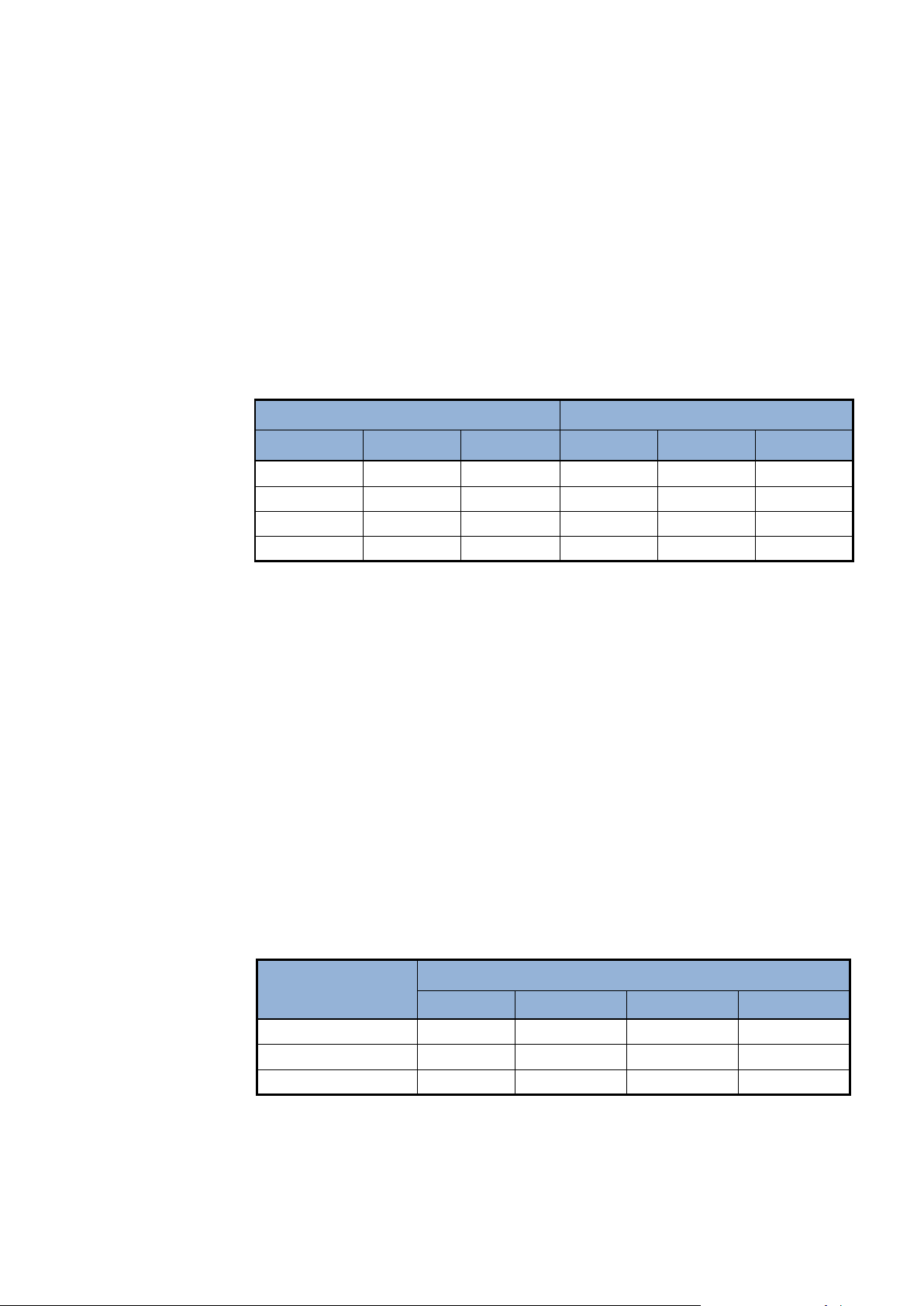
To determine the correct size for power cables need to be used for
third party power supply, refer to the below table (T he fol l owing table
lists examples of wire gauge and distance for a 12V):
Type of cable Length (m) at different currents
Network wire
Readers wires
AWG mm2 Ohm/Km
16 1.3 14 119 60 30
18 0.9 21 79 40 20
20 0.6 34 49 25 12
22 0.35 52 32 16 8
Table 1 - Length of Power Supply cables [m]
600 mA 1200 mA 2400 mA
Warning: The above table shows the values for a single Multi device;
if more than one Multi needs to be connected to the same line, divide
the length by the number of the devices.
For POE+ and POE: Cat5 or Cat6 Ethernet cable has to be used.
RS485 Data Cables (for OSDP reader connection)
Data cables used with RS485 must be twisted-pair and with 120 ohm
impedance.
Refer to Table 2 for the size of data cables to be used for this
connection with cable with AWG from 24 to 16 not shielded.
Communication
speed (bit/sec)
9600 1000 500 250 100
19200 500 250 125 50
38400 240 120 60 24
Table 2 - Length/Capacity of RS485 Data Cables not shi e lded (m)
Length in meters in relation to the cable capacity
50nF/Km 100nF/Km 200nF/Km 500nF/Km
Refer to Table 2 for sizing data cabl es to be used for RS485
connection with cable with AWG from 24 to 16 shielded.
15
Page 16
Input wires
Communication speed
(bit/sec)
9600 1200
19200 900
38400 700
Table 3 - Length of RS485 Data Cables shielded (m)
Length in meters
50nF/Km
Caution:
If the distance betw een the reader and the Multi
device is more that 15 m you need to change the
RS485 switch position to insert the 120 ohm
termination resistor. Refer to the Multi Device
Anatomy chapter
Wiegand reader cables
The wires used to connect Multi device with third party Wiegand
readers are those specified into the reader technical specification.
Use a twisted pair cable for the contacts connections.
For outdoor wiring is mandatory to use shielded cables.
For internal wiring without shielded cables is recommended an
electrical environment where the cables are well separated, even at
short runs, especially to whom can be essentially subjected to
interference.
The following table lists wire gauges and distances for Inputs.
Cable type Max distance (m)*
AWG mm2 Ohm/km
14 2 8.8 1420
16 1.3 14 893
18 0.9 21 595
20 0.52 34 368
22 0.35 52 240
24 0.2 85 147
26 0.13 137 93
Table 3 Length of Input cables
Output cable
16
*One-volt voltage drop is considered typical.
Cable used for connecting output should have a MAX size of 2 mm
that it is AWG14.
Page 17

MOUNTING THE DEVICE
Wall mount
These are the steps needed to be followed to mount the device on the
wall:
1. Determine an appropriate mounting position for the device;
keep into consideration that the wires shall be connected on the
top and bottom side of the box. To establish a common
reference the Ethernet connector should be on the right bottom
corner.
2. Use the back case to mark the position of the 4 mounting holes
Figure 4 - Multi back case and holes positions
3. Drill the holes
4. Introduce M6 (6 mm) plastic dowels (not included).
5. Attach the back case to the wall. No need to remove the board.
6. Setup jumpers for the desired configuratio n
7. Connect the readers
17
Page 18
DIN rail mount
These are the steps needed to be followed to mount the device on a
DIN rail:
8. Connect the inputs/outputs
9. Connect the power supply of the device.
10. Use screws to lock the cover of the device
1. Determine an appropriate mounting position for the device;
keep into consideration that the wires shall be connected on the
top and bottom side of the box. To establish a common
reference the Ethernet connector should be on the right bottom
corner.
2. Plug the device back case on the DIN Rail (use screw driver if
you need to unplug it).
3. Setup jumpers for the desired configuration
4. Connect the readers
5. Connect the inputs/outputs
6. Connect the power supply of the device.
7. Use screws to lock the cover of the device
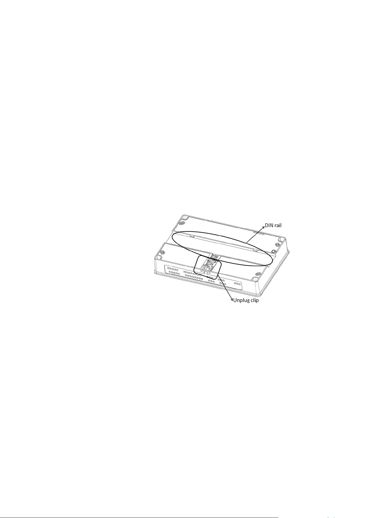
IP32 protection mount
The Voyager Multi device can be mounted to ensure IP32 protection
and so be in compliance with CEI EN-50133-1 group III - Outdoor but
sheltered from direct rain and sunshine or Indoor with extreme
environmental condition.
To achieve IP32 protection it is required to:
Figure 5 – Multi DIN rail and unplug clip
18
Page 19

1. Have the device mounted with Ethernet connector on the right
bottom corner.
2. Apply the adhesive seals rubber provided in the Device support
kit. The two seals are different in shape; the longer one is for
the top of the device where the shorter is for the bottom.
To wire the device when adhesive seals rubber are in place follow
these steps:
1. Using a screwdriver gently enlarge only the sealed holes need
to be used.
2. If the cable has stranded wires (flexible core) strongly twist the
stripped portion of the wire, in order to have a rigid tip, before
inserting it in the hole.
19
Page 20
CONNECTING THE CABLES
Caution:
To ensure IP32 protection to the device you must follow
what specified into “IP32 protection mount” chapter.
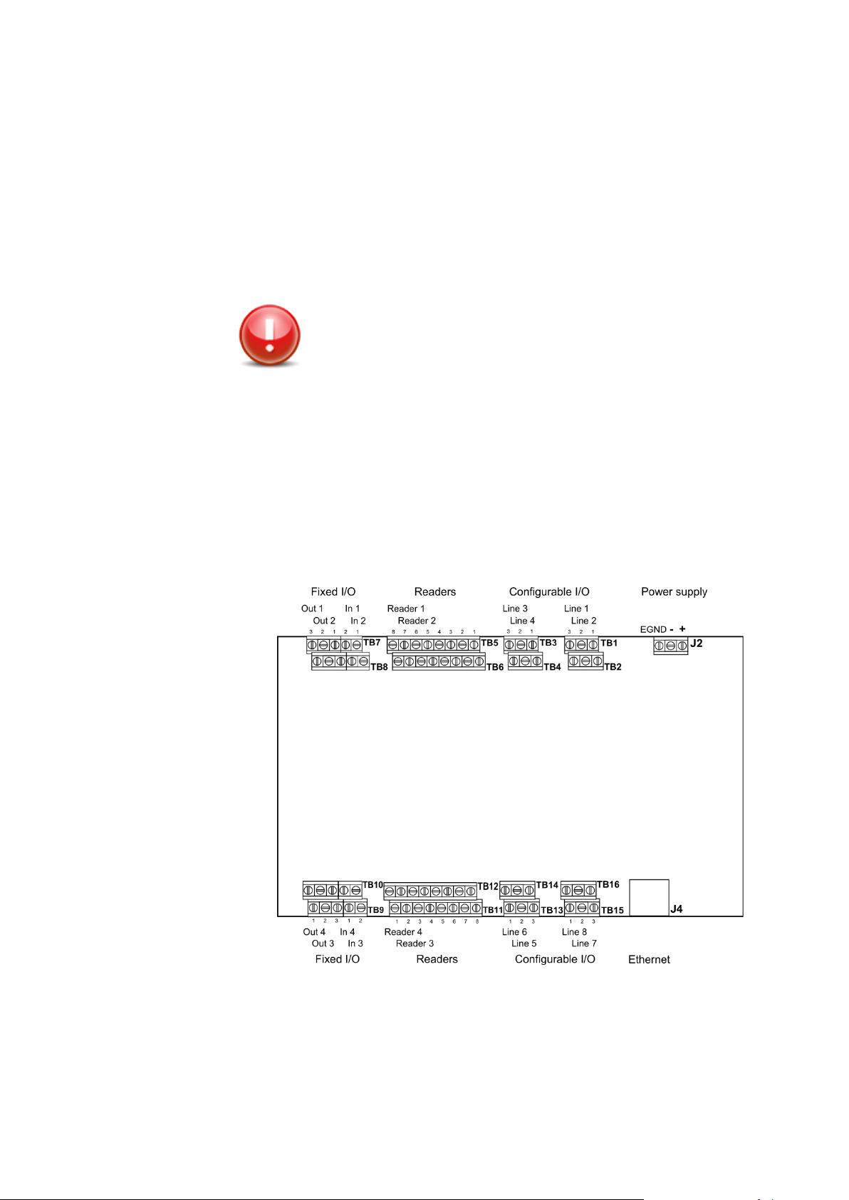
Cables to be connected are (see Figure 6 - Multi Wiring Diagram):
• DC power supply (only if the device is not supplied using
POE/POE+)
• Readers lines
• Ethernet (10/100/1G BaseT)
• Input/Outputs (both Fixed and Configurable)
20
Figure 6 - Multi Wiring Diagram
Page 21
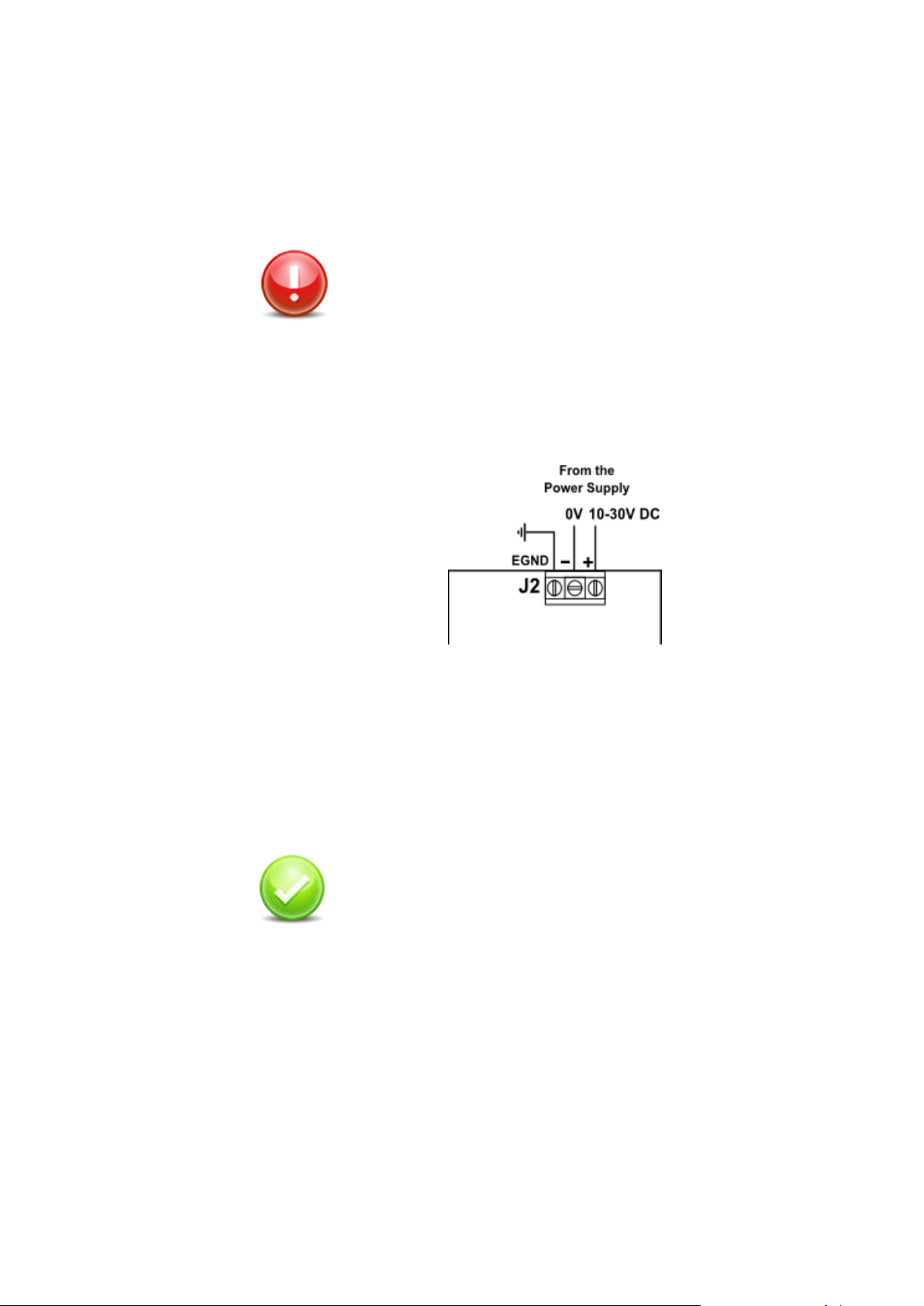
Connecting the DC Power Supply
The connection of an external power supply is required only if the
device is not supplied using POE or POE+.
Warning:
To be in compliance with UL60950 the Tema-Voyager Multi
device must be supplied by a separately certified NEC Class
2 (LPS) power unit.
1. Connect the DC Power supply cable heads onto the J2 terminal
blocks (use a ∅ 3mm slotted screwdriver).
2. Connect the ground wire (EGND).
Figure 7 - Multi - Power supply connections
The J2 connector is provided of a polarized direct screw connector
with the following connection characteristics:
• Conductor section AWG min = AWG24 max = AWG16
• Conductor rigid or flexible min = 0.2 mm2 max = 1.5 mm2
Check: Once the DC Power Supply is properly
connected and switched on, the LED9 Green Led (Power
Supply) must be in ON status.
21
Page 22
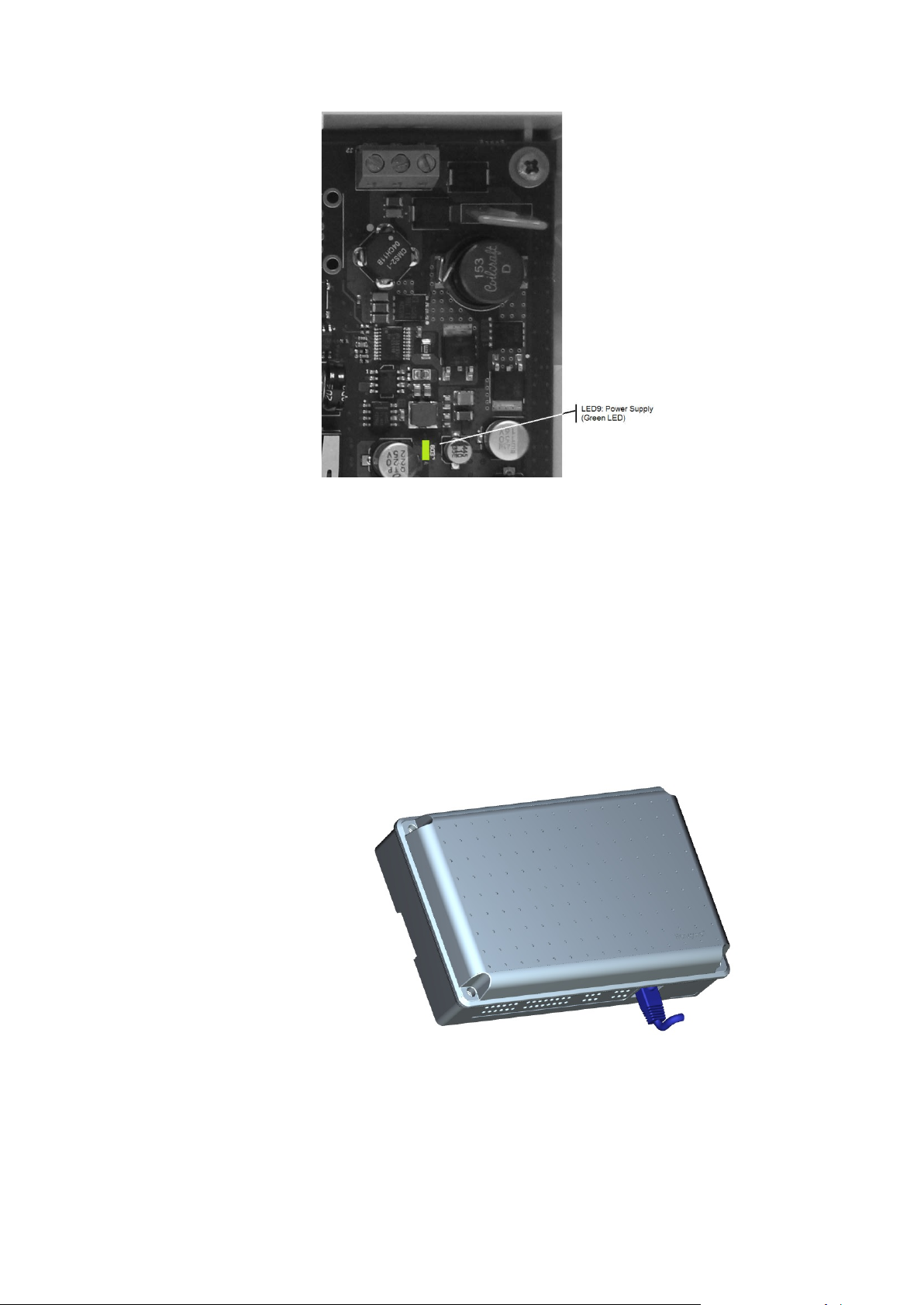
Figure 8 - Power supply LED
Connecting the netw or k cable
The Multi device is equipped with an RJ45 female connector J4.
The network cable must be a BaseT standard unshielded CAT5 or
CAT6 cable terminated with an RJ45 male connector.
Select the network cable in compliance to what specified into the
“Networ k wire” chapter on page 15.
Plug the cable into the J4 connector.
22
Figure 9 - Plug network connector
Characteristics of the network connection are:
Page 23
• Auto-MDIX: automatically detects and corrects for straight or
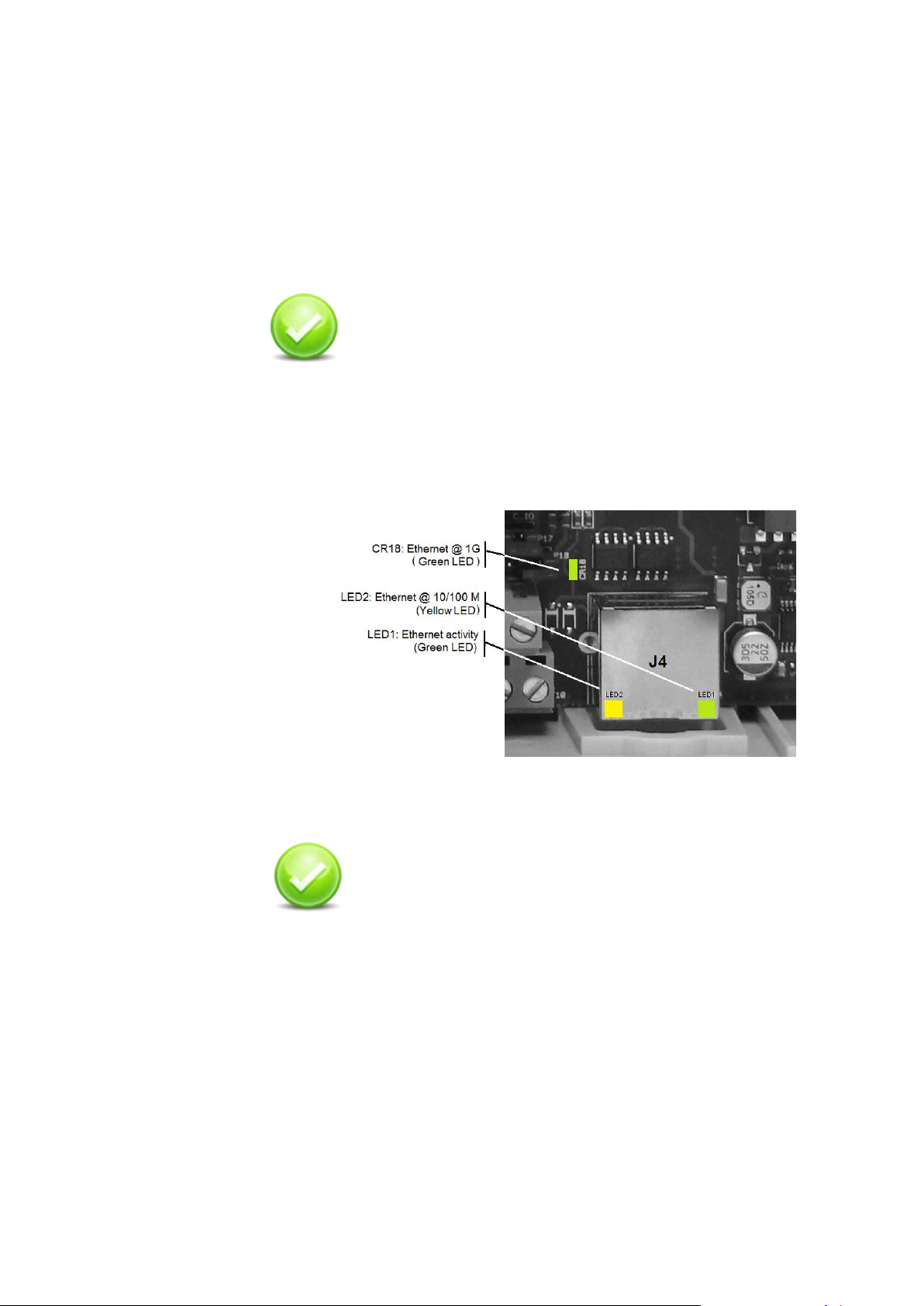
Check: once the Ethernet wire is properly connected and
• LED2 (green) - Ethernet @ 10/100 Mbit/s
• CR18 (green) - Ethernet @ 1 Gbit/s
blink regularly.
Check: in case of use of POE or POE+ as power supply
cross-over cables
• Error free operation up to 150mt: dependable network
performance over long distance
• > 8.0 KV ESD protection: robust operation in Harsh
environments
the Multi device switched on, one of the two led LED2 or
CR18 (Ethernet physical link) must be on. Which led is
switched on depends from the speed of the network:
The yellow LED1 (Ethernet Communication activity) must
Figure 10 - Ethernet LED positions
source once connected to Ethernet the device shall power
on and the green LED9 (Power supply) must be in on
status.
23
Page 24

Connecting the readers
Multi can connect up to 4 third party readers; connection can be
established using RS485 lines (for OSDP readers) or using Wiegand
line (for Wiegand readers).
The actual number of readers it is possible to connect depends from
the product code has been purchased (see: Multi device on page 12).
The connection position of the readers depends, as well, from product
code purchased:
Figure 11 - Power supply LED for POE/POE+
24
Code Reader
number
VMC-01WENN1 1 reader Reader1 (TB5)
VMC-02WENN1 2 readers Reader1 (TB5) and Reader2 (TB6)
VMC-03WENN1 3 readers Reader1 (TB5) and Reader2 (TB6) and
VMC-04WENN1 4 readers Reader1 (TB5) and Reader2 (TB6) and
Reader Connectors to be used
Reader3 (TB11)
Reader3 (TB11) and Reader4 (TB12)
Page 25

OSDP and Wiegand readers can be connected to the same terminal
blocks; to inform the device of the type of connection need to be used
it is required to set specific jumpers present on the board.
Multi is set in factory for the management of Wiegand
readers; this means that, on a brand new device, you
need to change the reader configuration jumpers only
if you need to connect OSDP readers.
The following pictures show for every reader position how to connect
the reader device and how to set the reader configuration jumpers in
case of Wiegand or OSDP reader.
Please note that to detect the tamper alarm of Wiegand reader it is
required to insert, closer to the reader device, the blue resistor
provided in the Devic e supp or t kit.
25
Page 26

Reader in position 1
The below pictures show the connections schematics and jumpers
setting for reader in position 1:
Wiegand reader
Reader in position 2
The below pictures show the connections schematics and jumpers
setting for reader in position 2:
OSDP reader
Wiegand reader
OSDP reader
26
Page 27

Reader in position 3
The below pictures show the connections schematics and jumpers
setting for reader in position 3:
Wiegand reader
Reader in position 4
The below pictures show the connections schematics and jumpers
setting for reader in position 4:
OSDP reader
Wiegand reader
OSDP reader
27
Page 28

OSDP reader check: once the connection with the
reader is properly established and configured, the Multi
and the reader are switched on; the bi-color LED (Red
and Green) must blink regularly. Red color indicates
transmission where green color receiving.
RS485 line length setti ng
On Multi device there is a series of switches used, when OSDP
readers are connected, to select RS-485 matched di stance mode.
Multi supports biasing and end-of-line termination for the RS-485
network. Please refer chapter “Switches and LEDs” on page 61 for the
position of the switches.
For every reader there are two switches, one for Data A and one for
Data B that need to be set both in the same way:
• When switch is OFF (terminator resistor is not inserted) RS-485
allows the wiring of single-drop communication network of up to
15 m in length.
• When switch is ON (terminator resistor is inserted) RS-485
allows the wiring of single-drop communication network of up to
1200 m in length.
Figure 12 - OSDP readers, communication LED positions
28
Page 29

OSDP
reader
Switch Meaning Default
Reader1 SW3.1 RS485 termination resistor, Data A.
ON = termination resistor inserted
OFF = termination resistor not inserted
SW3.2 RS485 termination resistor, Data B.
ON = termination resistor inserted
OFF = termination resistor not inserted
Reader2 SW4.1 RS485 termination resistor, Data A.
ON = termination resistor inserted
OFF = termination resistor not inserted
SW4.2 RS485 termination resistor, Data B.
ON = termination resistor inserted
OFF = termination resistor not inserted
Reader3 SW5.1 RS485 termination resistor, Data A.
ON = termination resistor inserted
OFF = termination resistor not inserted
SW5.2 RS485 termination resistor, Data B.
ON = termination resistor inserted
OFF = termination resistor not inserted
Reader4 SW6.1 RS485 termination resistor, Data A.
ON = termination resistor inserted
OFF = termination resistor not inserted
SW6.2 RS485 termination resistor, Data B.
ON = termination resistor inserted
OFF = termination resistor not inserted
OFF
OFF
OFF
OFF
OFF
OFF
OFF
OFF
Connecting Inputs
Multi provides four fixed inputs and other eight lines can be freely
configured as Inputs or Outputs; when lines are configured as input
these are called: Configurable inputs.
All the inputs can be either work as digital or supervised; this type of
configuration is done at the EBI level, so there are no jumpers on the
board for this type of setting.
The typical connection for supervised inputs requires using the couple
of yellow and white resistors distributed into the device support kit.
Yellow resistor: 1210 Ohm 1%
White resi stor: 392 Ohm 1%
Close contact resistance: 296 Ohm
Open contact resistance: 1210 Ohm
Table 4 - RS485 Terminator resistor switches
29
Page 30

Characteristics and connections are the same for fixed and
configurable inputs.
Connecting Fixed Inputs
Fixed Input 1
The below pictures show the connections schematics for dry contact
and supervised contact for fixed input 1:
Dry contact connection
Supervised connection
Fixed Input 2
The below pictures show the connections schematics for dry contact
and supervised contact for fix ed inp ut 2:
Dry contact connection
Supervised connection
30
Page 31

Fixed Input 3
The below pictures show the connections schematics for dry contact
and supervised contact for fix ed inp ut 3:
Dry contact connection
Supervised connection
Fixed Input 4
The below pictures show the connections schematics for dry contact
and supervised contact for fix ed inp ut 4:
Dry contact connection
Supervised connection
31
Page 32

Connecting configurable Inputs
Configurable Input 1
The below pictures show the connections schematics for dry contact
and supervised contact for configurable input 1:
Dry contact connection
Supervised connection
Configurable Input 2
The below pictures show the connections schematics for dry contact
and supervised contact for configurable input 2:
Dry contact connection
Supervised connection
32
Page 33

Configurable Input 3
The below pictures show the connections schematics for dry contact
and supervised contact for configurable input 3:
Dry contact connection
Supervised connection
Configurable Input 4
The below pictures show the connections schematics for dry contact
and supervised contact for configurable input 4:
Dry contact connection
Supervised connection
33
Page 34

Configurable Input 5
The below pictures show the connections schematics for dry contact
and supervised contact for configurable input 5:
Dry contact connection
Supervised connection
Configurable Input 6
The below pictures show the connections schematics for dry contact
and supervised contact for configurable input 6:
Dry contact connection
Supervised connection
34
Page 35

Configurable Input 7
The below pictures show the connections schematics for dry contact
and supervised contact for configurable input 7:
Dry contact connection
Supervised connection
Configurable Input 8
The below pictures show the connections schematics for dry contact
and supervised contact for configurable input 8:
Dry contact connection
Supervised connection
Caution: Temaline recommends that you establish
an electrical environment where the cables are well
separated, even at short runs, especially for the
power cables or external cables which can be
essentially subjected to interference or lightning.
Use a twisted-pair cable for the contact cables.
Make sure that the cables correspond in size to the
norms indicated in section Input wires.
Max contact resistance = 25 Ohm
35
Page 36

Connecting Outputs
Multi provides four fixed outputs and other eight lines can be freely
configured as Inputs or Outputs; when such lines are configured as
Outputs these are called: Configurable outputs.
Multi outputs are provided with open collector transistors.
Using the open collector directly (i.e. to connect an external relay), the
current must not exceed 50mA; when the load exceeds such value
is mandatory to use an external power supply.
In the following section we give the connection schematics in the case
of external relay powered directly from Multi and with relay powered
from an external power supply for both fixed output and for
configurable ones.
Note: Use 12VDC relay - max coil current = 50mA each. In this case
it’s mandatory to connect a 1N4004 diode as shown into schematics.
Multi can also be equipped with optional VMA-06 or VMA-07 relay
plugs-in (see chapter USING RELAYS PLUGS-IN (VMA-06, VMA-07)
on page 44 for these approach); to inform the board about the use of
external relays or Multi relay plugs-in on the board are present several
jumpers. Every schematic reports the relating setting of the jumpers.
The default jumpers’ configuration of Multi board (factory setting) is the
one used for external relay s.
36
Page 37

Connecting Fixed Outputs
Fixed Output 1
The below pictures show the connections schematics for an external
relay powered directly from Multi or from an external power supply
using fixed output 1:
External Relay Powered by Multi
External relay powered by
external power supply
Fixed Output 2
The below pictures show the connections schematics for an external
relay powered directly from Multi or from an external power supply
using fixed output 2:
External Relay Powered by Multi
External relay powered by
external power supply
37
Page 38

Fixed Output 3
The below pictures show the connections schematics for an external
relay powered directly from Multi or from an external power supply
using fixed output 3:
External Relay Powered by Multi
External relay powered by
external power supply
Fixed Output 4
The below pictures show the connections schematics for an external
relay powered directly from Multi or from an external power supply
using fixed output 4:
External Relay Powered by Multi
External relay powered by
external power supply
38
Page 39

Connecting Configurable Outputs
Configurable Output 1
The below pictures show the connections schematics for an external
relay powered directly from Multi or from an external power supply
using configurable out put 1:
External Relay Powered by Multi
External relay powered by
external power supply
Configurable Output 2
The below pictures show the connections schematics for an external
relay powered directly from Multi or from an external power supply
using configurable out put 2:
External Relay Powered by Multi
External relay powered by
external power supply
39
Page 40

Configurable Output 3
The below pictures show the connections schematics for an external
relay powered directly from Multi or from an external power supply
using configurable out put 3:
External Relay Powered by Multi
External relay powered by
external power supply
Configurable Output 4
The below pictures show the connections schematics for an external
relay powered directly from Multi or from an external power supply
using configurable out put 4:
External Relay Powered by Multi
External relay powered by
external power supply
40
Page 41

Configurable Output 5
The below pictures show the connections schematics for an external
relay powered directly from Multi or from an external power supply
using configurable out put 5:
External Relay Powered by Multi
External relay powered by
external power supply
Configurable Output 6
The below pictures show the connections schematics for an external
relay powered directly from Multi or from an external power supply
using configurable out put 6:
External Relay Powered by Multi
External relay powered by
external power supply
41
Page 42

Configurable Output 7
The below pictures show the connections schematics for an external
relay powered directly from Multi or from an external power supply
using configurable out put 7:
External Relay Powered by Multi
External relay powered by
external power supply
Configurable Output 8
The below pictures show the connections schematics for an external
relay powered directly from Multi or from an external power supply
using configurable out put 8:
External Relay Powered by Multi
External relay powered by
external power supply
42
Page 43

Outputs check: On Multi board are present 8 green LED
to monitor the Outputs state. To be able to use this
check the outputs must be properly configured and the
Multi switched on; Green color indicates output active
where LED switched o ff means output not configured or
inactive.
Figure 13 - Outputs monitor LED
43
Page 44

USING RELAYS PLUGS-IN (VMA-06, VMA-07)
Tema-Voyager™ Multi Relay Output board: provides 4
Relay Output, dry contact NO/NC 24V-3A.
Tema-Voyager™ Multi Emergenc y Relay Output board:
separate power supply.
VMA-06 and VMA-07 are optional plugs-in used together with Multi
devices. When these are plugged on the Multi board and properly
configured using the related jumpers they turn the open collector
digital outputs of the board in relay outputs.
VMA-07 includes the connection for an input that drives the cut of the
power supply of the device in case of emergency.
Up to 3 relay output plugs-in can be connected to Multi.
These are the product codes and the characteristics of the plugs-in:
Code Item
VMA-06
VMA-07
provides:
• 4 Relay Output, dry contact NO/NC 24V-3A;
• 1 Input, dry contact, for emergency alarm, with
44
Page 45

Figure 14 - VMA-06 relays Plug-in
Figure 15 - VMA-07 Relay Plug-in
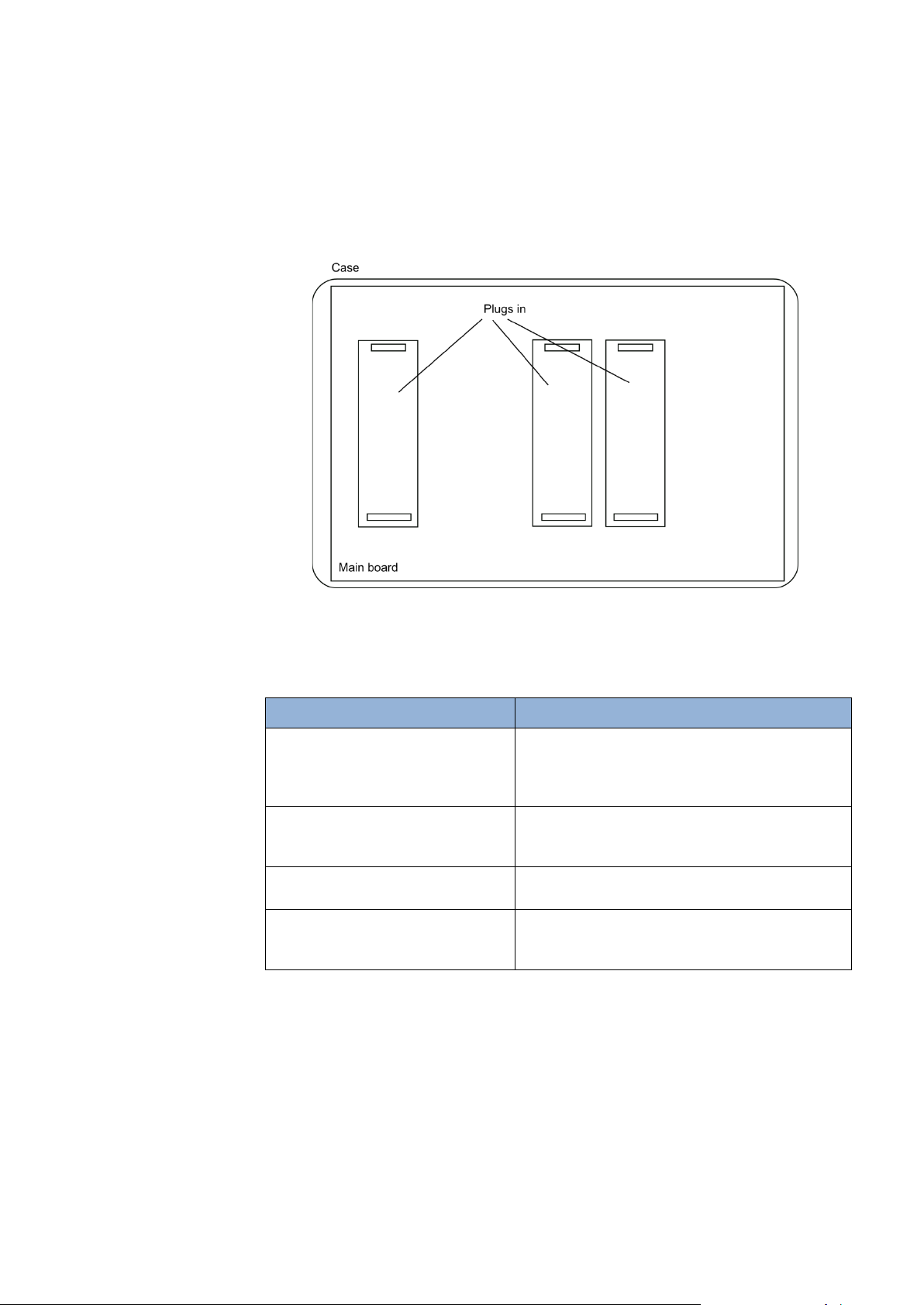
Mounting the plugs-in
To mount the plugs-in on the Multi device follows the below steps:
1. Determine an appropriate mounting position for the plugs in. If you
have a VMA-07 you have to plug it only on the position 1, where
VMA-06 can be plugged in any of the 3 sockets' positions (in
relation to the outputs to be managed).
a. Position 1 drives fixed outputs 1, 2, 3, 4
b. Position 2 drives flexible outputs 3, 4, 5, 6
c. Position 3 drives flexi bl e outpu ts 1, 2, 7, 8
45
Page 46

Figure 16 - Plugs-in position
2. Switch off the Multi device.
3. Unscrew the cover of the Voyager Multi case and remove it.
4. Plug the VMA-0x devices on the Multi board.
46
Figure 17 - Plugging the VMA-06 on position 1
Caution:
The plugin has two connectors, one with 8 pins and
another with 6 pins, this has to be matched with the
socket on the main board
5. Set the jumpers required to configure the use of the plug-in
(see for details: Configurati on o f Multi t o use VM A-06 and VMA07 plugs-in on page 48)
6. Wire the outputs as specified in the following of the chapter.
Page 47

7. If you are using VMA-07 wire the input used to cut the
1
2
3
POE/POE+ internal power supply (see for det ai l s: Connection
of the emergency input to VMA-07 on page 55).
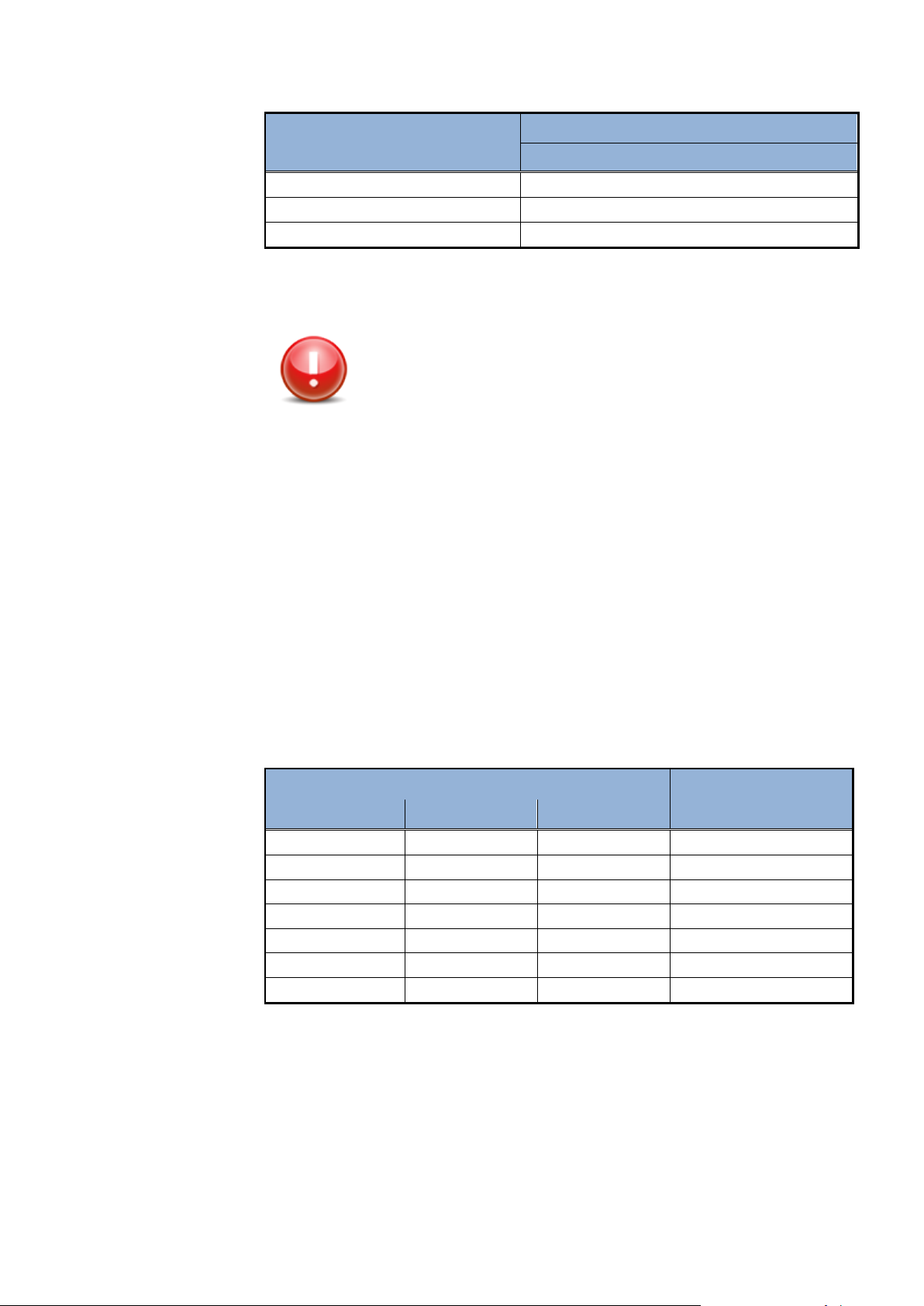
Setting up Plug-in jumper
On VMA-06 and VMA-07 each jumpers block is relating to a single
output; the below picture and table give the match between ju mper s
block and outputs based on the position of the plug-in on the board.
Figure 18 - Jumpers blocks on plugs-in
Plug-in position Outputs match
P5 – Fixed output1
P3 – Fixed output2
Table 5 - Matches between jumpers blocks and outputs
P4 – Fixed output3
P6 – Fixed output4
P5 – Line3
P3 – Line4
P4 – Line5
P6 – Line6
P5 – Line1
P3 – Line2
P4 – Line7
P6 – Line8
Specific position of jumpers on the jumper block is used to specify one
of the four modes in which the relay outputs can work:
• Dry contact normally open (default jumper setup)
47
Page 48

• Dry contact normally closed
• Power output normally open
• Power output normally closed
The below picture shows the way to set the jumpers to have the
desired mode:
Figure 19 - Relay output mode
Configuration of Multi to use VMA-06 and VMA-07 plugs-in
To use relay outputs on VMA-06 and VMA-07 plugs-in it is required to
properly configure the jumpers on Multi board.
In the following pictures we show all the possible configuration of Multi
to use plugs-in relay outputs. For every configuration is shown also the
related Jumper settings.
Caution:
After inserting VMA-06 and VMA-07 plugs-in it is
required to configure some jumpers on Multi board
to drive the outputs through relays.
48
Page 49

Connecting Fixed Outputs (Plug-in in slot of position 1)
Door Lock Powered by Multi relay
Door lock powered by external
NC
Door Lock Powered by Multi relay
Door lock powered by external
NC
The below pictures show the connections schematics for Multi using
VMA-06 or VMA-07 plugs-in and fixed output s: a door lock powered by
Multi relay and a door lock power from an external power supply and
driven by an internal relay used as dry contact. Wiring of outputs and
jumper configuration are done in the same way for VMA-06 and VMA-
07. VMA-06 or VMA-07 plug-in must be inserted in slot 1.
Fixed Output 1
Relay output mode:
Power Output NO (as in above picture) or NC
Fixed Output 2
power supply and driven by Multi
relay
Relay output mode:
Dry Contact NO (as in above picture) or
power supply and driven by Multi
relay
49
Relay output mode:
Power Output NO (as in above picture) or NC
Relay output mode:
Dry Contact NO (as in above picture) or
Page 50

Fixed Output 3
Door Lock Powered by Multi relay
Door lock powered by external
NC
Door Lock Powered by Multi relay
Door lock powered by external
NC
Relay output mode:
Power Output NO (as in above picture) or NC
Fixed Output 4
power supply and driven by Multi
relay
Relay output mode:
Dry Contact NO (as in above picture) or
Relay output mode:
Power Output NO (as in above picture) or NC
power supply and driven by Multi
relay
Relay output mode:
Dry Contact NO (as in above picture) or
50
Page 51

Connecting Configurable Outputs (Plug-in in slot of position 2)
Door Lock Powered by Multi relay
Door lock powered by external power
NC
Door Lock Powered by Multi relay
Door lock powered by external power
NC
The below pictures show the connections schematics for Multi using
VMA-06 plugs-in and configurable out put s : a door lock powered by
Multi relay and a door lock power from an external power supply and
driven by an internal relay used as dry contact. VMA-06 plug -in must
be inserted in slot of position 2.
Configurable Output 3
Relay output mode:
Power Output NO (as in above picture) or NC
Configurable Output 4
supply and driven by Multi relay
Relay output mode:
Dry Contact NO (as in above picture) or
Relay output mode:
Power Output NO (as in above picture) or NC
supply and driven by Multi relay
Relay output mode:
Dry Contact NO (as in above picture) or
51
Page 52

Configurable Output 5
Door Lock Powered by Multi relay
Door lock powered by external power
NC
Door Lock Powered by Multi relay
Door lock powered by external power
NC
Relay output mode:
Power Output NO (as in above picture) or NC
supply and driven by Multi relay
Relay output mode:
Dry Contact NO (as in above picture) or
Configurable Output 6
Relay output mode:
Power Output NO (as in above picture) or NC
supply and driven by Multi relay
Relay output mode:
Dry Contact NO (as in above picture) or
52
Page 53

Connecting Configurable Outputs (Plug-in in slot of position 3)
Door Lock Powered by Multi relay
Door lock powered by external power
NC
Door Lock Powered by Multi relay
Door lock powered by external power
NC
The below pictures show the connections schematics for Multi using
VMA-06 plugs-in and configurable out put s : a door lock powered by
Multi relay and a door lock power from an external power supply and
driven by an internal relay used as dry contact. VMA-06 plug -in must
be inserted in slot of position 3.
Configurable Output 1
Relay output mode:
Power Output NO (as in above picture) or NC
Configurable Output 2
supply and driven by Multi relay
Relay output mode:
Dry Contact NO (as in above picture) or
Relay output mode:
Power Output NO (as in above picture) or NC
supply and driven by Multi relay
Relay output mode:
Dry Contact NO (as in above picture) or
53
Page 54

Configurable Output 7
Door Lock Powered by Multi relay
Door lock powered by external power
NC
Door Lock Powered by Multi relay
Door lock powered by external power
NC
Relay output mode:
Power Output NO (as in above picture) or NC
supply and driven by Multi relay
Relay output mode:
Dry Contact NO (as in above picture) or
Configurable Output 8
Relay output mode:
Power Output NO (as in above picture) or NC
supply and driven by Multi relay
Relay output mode:
Dry Contact NO (as in above picture) or
54
Page 55

Connection of the emergency input to VMA-07
When the door lock is powered by the Multi (POE/POE+ or
+12V) using the VMA-07 relay plug-in, it’s possibl e to con nect an
external dry contact signal (normally closed) used to cut the
power of the door lock. This can be used in case of emergency
like a fire alarm.
The J1 terminal block is opto-isolated; this allows connecting
simultaneously several emergency Inputs.
Figure 26 – VMA-07 Emergency input
The two wires must enter in the Multi case from the two holes
located on the right of the first group of holes on the bottom of the
device (see picture)
Figure 27 – Emergency input holes
55
Page 56

FINAL OPERATIONS
Closing the device
To close the terminal, follow these steps:
1. Position the cover with the corner with “Honeywell label” in the
lower right (this is important to properly close the anti-tamper
switch).
2. Close the device cover.
3. Secure the cover by mean of the 4 torx screws (see Figure 20);
this operation requi res a TORX anti-tamper T10 screwdriver.
Commissioning tips
Commissioning of the device is outside the scope of this manual,
never the less we will include here some tips on this activity
addressing you to the EBI documentation f or the ful l detai ls :
EBI - Temaline Access Control Configuration Guide
56
Figure 20 Multi cover
Page 57

Configuring the Voyager Multi
Factory default IP Address
A device from factory is configured with this default IP address:
After the first connection, the IP address must be changed because, to
avoid conflicts, every device in the network must have a different
address.
To change the IP address please refers to:
EBI - Temaline Access Control Configuration Guide
Configuring the Voyager Device
Factory FW version
A device is shipped from factory with a running version of the FW
application corresponding to the most recent version, available at the
manufacturing time, of the released FW.
The installed version may not be suitable for your plant or a more
recent version of the FW could be available.
You should verify the FW version installed on your device and check
the Temaline compatibi l i ty tables distributed on the EBI Global
Support site.
To verify the FW application version running on the device and to
update the FW version please refers to:
Tema-Voyager Multi - Web Interface Guide
160.221.230.127
57
Page 58

MULTI DEVICE ANATOMY
VMA-06VMA-06VMA
-06/VMA-07
MULTI
Enclosure
Figure 22 is a picture of the Multi device board in it case.
Figure 21 – Photo of Multi device board
Figure 22 provides a graphical representation of the MULTI device
and of the boards (Main board and VMA-0x plugs-in).
Figure 22 Graphical representation of Multi device and VMA-0x plugs-in
58
Page 59

Terminal Blocks and Jumpers
Terminal Blocks
Figure 23 - Position of terminal blocks and jumpers (factory configuration)
The above picture shows the position of Terminal Blocks and Jumpers
on the Voyager Multi board.
The below table lists the terminal blocks and explain their meaning.
Terminal Block Meaning
TB1 Configurable I/O line 1
TB2 Configurable I/O line 2
TB3 Configurable I/O line 3
TB4 Configurable I/O line 4
TB5 Reader1
TB6 Reader2
TB7 Fixed Input 1 and Fixed Output 1
TB8 Fixed Input 2 and Fixed Output 2
TB9 Fixed Input 3 and Fixed Output 3
TB10 Fixed Input 4 and Fixed Output 4
TB11 Reader3
59
Page 60

Jumpers
TB12 Reader4
TB13 Configurable I/O line 5
TB14 Configurable I/O line 6
TB15 Configurable I/O line 7
TB16 Configurable I/O line 8
Table 6 Terminal blocks
The below table lists the Jumpers and explain their meaning.
Jumper Meaning
P01 External tamper
P02 Console serial line
P03 Configurable Output 4 relay selector
P04 Fixed Output 4 relay selector
P05 Fixed Output 4 relay selector
P07 Fixed Output 3 relay selector
P08 Fixed Output 3 relay selector
P09 Fixed Output 2 relay selector
P10 Fixed Output 2 relay selector
P11 Fixed Output 1 relay selector
P12 Fixed Output 1 relay selector
P13 Configurable Output 3 relay selector
P14 Configurable Output 3 relay selector
P15 Configurable Output 8 relay selector
P16 Configurable Output 8 relay selector
P17 Configurable Output 7 relay selector
P18 Configurable Output 7 relay selector
P19 Configurable Output 2 relay selector
P20 Configurable Output 2 relay selector
P21 Configurable Output 6 relay selector
P22 Configurable Output 6 relay selector
P23 Configurable Output 5 relay selector
P24 Configurable Output 5 relay selector
P25 Configurable Output 1 relay selector
P26 Configurable Output 4 relay selector
P27 Configurable Output 1 relay selector
P29 Reader 1 Wiegand/OSDP selector
P30 Reader 2 Wiegand/OSDP selector
P31 Reader 1 Wiegand/OSDP selector
P32 Reader 1 Wiegand/OSDP selector
60
Page 61

Switches and LEDs
P33 Reader 2 Wiegand/OSDP selector
P34 Reader 2 Wiegand/OSDP selector
P35 Reader 3 Wiegand/OSDP selector
P36 Reader 4 Wiegand/OSDP selector
P37 Reader 3 Wiegand/OSDP selector
P38 Reader 3 Wiegand/OSDP selector
P39 Reader 4 Wiegand/OSDP selector
P40 Reader 4 Wiegand/OSDP selector
Table 7 Jumpers
Switches
Figure 33 – Switches and LEDs
The below table lists the switches and explain their meani ng .
Switch Function Default
SW1.1 Application Switches: Spare. SW1.2 Application Switches: FW application roll back.
See Appendix 1 for details.
SW1.3 Application Switches: Restore Factory
See Appendix 1 for details.
SW1.4 Application Switches: Linux Console activation Open
Open
Open
61
Page 62

See Appendix 1 for details.
SW1.5 Application Switches: Spare SW1.6 Application Switches: Manufacturing test.
DO NOT USE: This feature is used for factory test.
See Appendix 1 for details.
SW3.1 RS485 (Reader 1) termination resistor, Data A.
ON = termination resistor inserted
OFF = termination resistor not inserted
SW3.2 RS485 (Reader 1) termination resistor, Data B.
ON = termination resistor inserted
OFF = termination resistor not inserted
SW4.1 RS485 (Reader 2) termination resistor, Data A.
ON = termination resistor inserted
OFF = termination resistor not inserted
SW4.2 RS485 (Reader 2) termination resistor, D ata B.
ON = termination resistor inserted
OFF = termination resistor not inserted
SW5.1 RS485 (Reader 3) termination resistor, Data A.
ON = termination resistor inserted
OFF = termination resistor not inserted
SW5.2 RS485 (Reader 3) termination resistor, D ata B.
ON = termination resistor inserted
OFF = termination resistor not inserted
SW6.1 RS485 (Reader 4) termination resistor, Data A.
ON = termination resistor inserted
OFF = termination resistor not inserted
SW6.2 RS485 (Reader 4) termination resistor, D ata B.
ON = termination resistor inserted
OFF = termination resistor not inserted
SW7 System reset Open
Open
Open
Open
Open
Open
Open
Open
Open
Open
LED
62
Table 8 - Switches
The below table lists the led and explain their meaning.
LED Function Values
CR18 Ethernet 10/100M bit/s Green
CR25 Database status, Red ON=Database not present
ON= Ethernet working at
10/100M bit/s
OFF=Ethernet not working at
10/100M bit/s
OFF= Database present
Page 63

CR68 RS485 2 TX/RX activity, Bi-color
LED, Red and Green
CR69 RS485 3 TX/RX activity, Bi-color
LED, Red and Green
CR70 RS485 4 TX/RX activity, Bi-color
LED, Red and Green
CR78 Application status, Green ON=Application running
CR96 EBI communication, Red ON=Communication with EBI
RJ45.1 Ethernet TX/RX activity
Green
RJ45.2 Ethernet physical link, 1G bit/s
Yellow
LED1 Configurable I/O 1
Green LED
LED2 Configurable I/O 2
Green LED
LED3 Configurable I/O 3
Green LED
LED4 Configurable I/O 4
Green LED
LED5 Configurable I/O 5
Green LED
LED6 Configurable I/O 6
Green LED
LED7 Configurable I/O 7
Green LED
LED8 Configurable I/O 8
Green LED
LED9 DC or POE Power in LED,
Green,
Red Blinking when TX is active
Green Blinking when RX is active
OFF=no RX/TX activity
Red Blinking when TX is active
Green Blinking when RX is active
OFF=no RX/TX activity
Red Blinking when TX is active
Green Blinking when RX is active
OFF=no RX/TX activity
OFF= Application stopped
stopped
OFF= Communication with EBI in
place
Blinking when RX or TX is active
OFF= no RX/TX activity
ON=Good link
OFF=no link or no 1G bit/s
ON= Output
OFF= Input
ON= Output
OFF= Input
ON= Output
OFF= Input
ON= Output
OFF= Input
ON= Output
OFF= Input
ON= Output
OFF= Input
ON= Output
OFF= Input
ON= Output
OFF= Input
ON=DC/POE present
OFF=DC/POE not present
Device Tampers
Anti open tamper
An anti-open tamper S1 is present into the devi ce. When the case is
closed the tamper switch is pressed and so switched off.
63
Table 9 - Led
Page 64

External tampers connection
The Jumper P1 present on Multi is designed to connect an external
tampers for the device (not provided).
Such tamper could be used as anti removal tamper for the device or to
connect the anti open tamper of an external case who hosts the Multi
device.
From factory, and when external tamper is not used, P1 is closed with
a jumper.
Figure 24 – External Tamper Connector
If you need to connect an external tamper to the connector P1 you can
use the below schematic.
Figure 25 - External tamper connection schema
Please note that:
P1 and the device anti-open tamper are in serie s
and thus it is not possible to distinguish which of
the two tampers raised the alarm. From the
supervision center the two tampers generate the
same events.
64
Page 65

OPERATING INSTRUCTIONS & MAINTENANCE
Reset Multi device
To reset Multi device press for at least 3 seconds the SW7 Reset
Button located on the upper left corner of the device.
Switch off Multi device
To switch off the unit, follow these steps:
1. Open the unit by unscrewing the four screws on the front cover
(requires TORX Tamper-Resistant T10 scre wdriver).
2. Unscrew the +Vcc wire on J2 connector or, if the device is
supplied with POE/POE+, disconnect the Ethernet cable.
65
Figure 26 - Multi Reset button
Page 66

Multi application quick health check
Using diagnostic Led, present on to the Multi main board, it is possible
to perform a first quick check of the application without the use of SW
tools.
Check the chapter “MULTI DEVICE ANATOMY ” on page 58 for LED
and reset button positions.
The below table shows the checks that is possible to perform, t he Le d
to be checked and possible approaches to overcame the issues.
Function Led and
status
Ethernet
Communication
Application
running
EBI
communication
Data Base
status
RJ45.1
OFF
CR78
OFF
CR96
ON
CR25
ON
Possible
failure(s)
No Ethernet
communication
Application not
running
No communication
with EBI
Database not
present
Approach
• Check the Ethernet
wiring.
• Check the status of the
network.
• Reset the device using
reset button.
• Check if the
supervision centre is up
and running
• Check if the Multi
device is properly
configured into EBI.
• Check the Ethernet
communication.
Without supervision centre
communication there will
not be any DB download,
so:
• Check if the
supervision centre is
up and running.
• Check if the Multi
device is properly
configured into EBI.
• Check the Ethernet
communication.
66
Table 10 – Multi application quick health checks
Page 67

CONDITIONS RESULTING IN IMPAIRED OPERATION
Impaired operation conditions Impaired operation result
12VDC connected in reverse way The protection inside the Multi will
avoid permanent damage
Connect the input port to output port The 12Vcc will be distributed to the
contact/detector; this can damage
the detector or create a short
circuit. Power supply Output alarm
will be activated. Check the cabling
before to switch on the main power
Connect the output port to input port Input short/cut alarm is activated.
Check the cabling before to switch
on the main power
Plug-in inserted in a reverse wa y The protection inside the Multi will
avoid permanent damage
Table 11 - Condition resulting in impaired operation
67
Page 68

PROTECTIVE FEATURES (WA R NING OF BYPASSING)
Unit Name Protective features and warning
Multi To reduce the electric shock risk, do not wire the device
during power on condition
Multi To reduce the fire risk, do not operate the device over the
operating temperature.
Table 12 - Protective features and warning
68
Page 69

TECHNICAL SPECIFICATIONS
POE+ power supply
POE+ IEEE 802.3at-2009
Available current for
readers and locks
(supported only with
Wiegand connection
4 monitored lines, alternative to the 4 RS485 lines
Parameter Value
DC power supply 10-30VDC (f or UL60950 compliance units mus t be supplied by a
separately certified NEC Class 2 (LPS) power unit)
POE power supply POE IEEE 802.3af-2003
Power consumption 4,8 W Board only
DC power supply: max 36 W
POE+: max 25.5W
POE: max 15.4W
DC power supply: max 1500mA @ 12Vcc
POE+ : max 1500mA @ 12Vcc
VMA-06, VMA-07 plug-in)
Inputs 4 fixed:
Outputs 4 fixed:
Input/Output lines 8 configurable (same characteristics of the fixed input/output)
Electrical
Microprocessor Freescale i.MX 6 SOLO 800 Mhz
Flash Memory High reliability NOR Flash 128 Mbytes
SDRAM memory High performance DDR SDRAM 512 Mbytes
Real Time Clock Internal RTC; retention time 48 hours using super capacitor.
LAN Ethernet connection 10Mb/100Mb/1Gb BaseT standard unshielded cable on RJ45;
RS485 connection 4 lines (OSDP protocol), alternative to the 4 W iegand lines
Technical
Size 240*140*60mm
Weight
(including carton box)
Case PC+ABS UL V0 Thickness: 2.5mm
Physical
POE : max 750mA @ 12Vcc
WARNING: check limits with Tema-Voyager Multi Consumption
Verifier tool
Supervised inputs with f our s tatuses : N ormal, Alarm, Cut, and Short
or two statuses: Open, Close.
Current: 0~10mA for each input
Voltage: +14V maximum; 0V minimum
Min detection time: 50ms
From the main Board: Power Open Drain (Mosfet) 12V-50mA
From the optional Relay Output board: dry contact NO/NC 24V-3A
Operative system LINUX
POE, POE+
550g
Not painted; Color: Grey RAL 7035
69
Page 70

Mounting Wall or DIN rail mounting
temperature for correct
Storage and operating
Security screw 4 Torx screws
Anti-Tampering 1 internal switch (against opening)
Protection level IP32
Environmental
operation
Storage temperature
humidity
Environmental
-10°C to +55°C
-25°C ÷ 70°C
0÷95% not condensing
70
Page 71

REGULATIONS
Company name: Honeywell S.r.l. Via Philips, 12 20052 Monza Italy
EN 50581: 2012
Company name: Honeywell S.r.l. Via Philips, 12 20052 Monza Italy
CE Compliance
Product name: Tema-Voyager™ Multi
Product models: VMC-00WENN1, VMC-01WENN1, VMC-02WENN1, VMC03WENN1, VMC-04WENN1, VMA-06, VMA-07.
Are in conformity with the European Union following harmonization legislation:
Directives:
Electromagnetic Compatibility Directive (2014/30/EU)
General Product Safety Directive (2001/95/EC)
RoHS EU Directive ( 2011/65/EU)
Standards:
EN 50130-4:2011+ A1:2014
EN 55032:2012 + AC:2013
EN 60950-1:2006 + A11:2009 + A1:2010 + A12:2011 + A2:2013
“Access Control System for use in Security
Applications” Compliance
Product type: Tema-Voyager™ Multi
Product models: VMC-00WENN1, VMC-01WENN1, VMC-02WENN1, VMC03WENN1, VMC-04WENN1, VMA-06, VMA-07.
Are in conformity with the following harmonized standard(s) and other
normative document(s):
EN 50133-1:1996/A1:2002
EN 50133-2-1: 2000
EN 50133-7:1999
In accordance to requirements for Security class equipments:
Recognition class: 2, 3
Access class: B
Environment Class: II
71
Page 72

Company name: Honeywell S.r.l.
operate this equipment.
UL60950
FCC Notice
Identification code: VMC-00WENN1 VMC-01WENN1 VMC-02WENN1 VMC03WENN1 VMC-04WENN1.
This device complies with CFR 47 FCC part 15 subpart B, 2014 rules.
Operation is subject to the two following conditions:
Cet appareil est conforme à la section 15 des réglementations de la FCC. Le
fonctionnement de l’appareil est sujetaux deux conditions suivantes :
(1) cet appareil ne doit pas provoquer d’interférences néfastes, et
(2) cet appareil doit tolérer les interférences reçues, y compris celles qui
risquent de provoquer un fonctionnement indésirable.
This equipment has been tested and found to comply with the limits for a
Class B digital device, pursuant to Part 15 of FCC Rules. These limits are
designed to provide reasonable protection against harmful interference in a
residential installation. This equipment generates, uses and can radiate radio
frequency energy and, if not installed and used in accordance with the
instructions, may cause harmful interference to radio communications.
However, these is no guarantee that interference will not occur in a particular
installation.
If this equipment does cause harmful interference to radio or television
reception, which can be determined by tuning the equipment off and on, the
user is encouraged to try to correct the interference by one or more the
following measures:
• Reorient or relocate the receiving antenna.
• Increase the separation between the equipment and receiver.
• Connect the equipment into an outlet on a circuit different from that to
• Consult the dealer or an experienced radio/TV technician for help.
The user is cautioned that changes and modification made to the equipment
without the approval of the manufacturer could void the user's authority to
• This device may not cause harmful interference and
• This device must accept any interference received, including
interference that may cause undesired operations.
which the receiver is connected.
72
Canadian and United States UL Listed
Reference File: E221152. UL's investigation of this product has been
completed under the above Reference Number and the product was
determined to comply with the applicable requirements.
Page 73

Australian CTick Conformity
Applicant: Honeywell S.r.l.
The device is compliant with the European Parliament and Council Directive
Directives 2011/65/EU
In accordance with directive 2012/19/EU regarding waste electrical and
This product contains toxic and hazardous substances or elements over the
and needs to enter into the recycling system when this period is over.
Applicant Number: SHEM1503000790IT
Model numbers: VMC-00W ENN1, VMC-01WENN1, VMC-02WENN1, VMC-
03WENN1, VMC-04WENN1.
For compliance levels 1, 2 and 3 in Australia As required by notices
under: Section 182 of the Australian Radio communications Act 1992.
The product complies with the requirements of the Radio communications
(Electromagnetic Compatibility) Standard 2008. Evidence of compliance is
demonstrated by test reports to the following applicable standards: AS/NZ
CISPR 22: 2009+A1:2010 Information technology equipment - Radio
disturbance characteristics - Limits and methods of measurement.
RoHS compliance
on the restriction on the use of certain Hazardous Substances in electrical and
electronic equipment devices.
WEEE compliance
electronic apparatus (effective since 14 February 2014), Honeywell commits,
when requested by the customer, to the collection, treatment, recovery, and
disposal of the apparatus produced.
Customers in the European Union are advised to dispose this product, at the
end of its useful life, in accordance with local laws, regulations, and
procedures.
China RoHS declaration
defined maximum concentration values defined by the regulation. The product
can be used safely during its environmental protection use period (15 years)
73
Page 74

Appendix 1 - Application switches
Please note that:
Application switches can be used only for
maintenance purpose and only on request of
Technical Assistance Center personnel.
Jumper Function Default state
SW1.1 Spare position Close
SW1.2 FW application rolls back. When the jumper is closed and
the device is restarted, it restores the alternative version
of the application present on the device (if any).
To be able to work again with the device after the reboot,
the jumper must be set back to Open.
Open = current FW application valid
Close = force FW application roll back
SW1.3 Restore the device to Factory configuration.
When the jumper is closed and the device is restarted, the
factory configuration is restored to: all data present in the
memory and in the DB of the device is lost and the
communication parameters are reset to the factory default
values. In particular IP address of the device is set to
160.221.230.127.
To be able to work again with the device after the reboot,
the jumper must be set back to Open.
Open = Use current configuration
Close = restore factory configuration
SW1.4 Linux Console activation. This jumper is used for
activating the LINUX Console of the device. When the
jumper is closed and the device is restarted, the use of the
console is enabled. The activation of LINUX console may
be required only for deep debug purpose; don't change
this jumper if it is not specifically required from Honeywell
Technical Assistance Center.
Open = Linux console not active
Close = Linux console active
SW1.5 Spare position Open
SW1.6 Manufacturing test. The jumper is activated when you
boot the Manufacturing Test Application instead of the FW
Application. This Jumper is used for testing in the factory
only. Not suitable for field operations.
Open = FW application active
Close = Manufacturing Test active
Open
(Current FW
application is
valid)
Open
(Use current
configuration)
Open
(Linux console
not active)
Open
(FW application
active)
74
Page 75

Appendix 2 – Meaning of graphical symbols used
Keep away from rain
Canadian and United States UL Listed
In compliance with “EN60950 Amendment 2 – Information Tec hnology
– Safety, General Requirements” this appendix shows the list of
graphical symbols used in the product and their meanings.
Symbol Meaning Located
on
Carton Box
To indicate that the transport package shall
be kept away from rain and in dry
conditions.
Fragile; handle with care
Carton Box
To indicate that the contents of the
transport package are fragile and the
package shall be handled with care.
This way up
Carton Box
To indicate correct upright position of the
transport package.
Conformité Européenne
Label
To indicate the manufacturer declares that
the product meets the requirements of the
applicable EC directives
To indicate that the product meets the
requirements of the UL60950
regulation
Recycling
Label
Label
To indicate compliance with EC directive
regarding waste electrical and electronic
apparatus.
75
Page 76

China RoHS environmental protection
use period
Indicates the environmental protection use
period of the product.
Label
76
 Loading...