


Thor™ VM2WG
Vehicle-Mount Computer
Microsoft® Windows® Embedded Standard Operating System
User's Guide

Disclaimer
Honeywell International Inc. (“HII”) reserves the right to make changes in specifications and other information contained in this
document without prior notice, and the reader should in all cases consult HII to determine whether any such changes have
been made. The information in this publication does not represent a commitment on the part of HII.
HII shall not be liable for technical or editorial errors or omissions contained herein; nor for incidental or consequential damages
resulting from the furnishing, performance, or use of this material.
This document contains proprietary information that is protected by copyright. All rights are reserved. No part of this document
may be photocopied, reproduced, or translated into another language without the prior written consent of HII.
© 2012-2013 Honeywell International Inc. All rights reserved.
Web Address:
RFTerm is a trademark or registered trademark of EMS Technologies, Inc. in the United States and/or other countries.
Microsoft®Windows, ActiveSync®, MSN, Outlook®, Windows Mobile®, the Windows logo, and Windows Media are
registered trademarks or trademarks of Microsoft Corporation.
Intel®and Atom™ are trademarks or registered trademarks of Intel Corporation or its subsidiaries in the United States and
other countries.
Summit Data Communications, the Laird Technologies Logo, the Summit logo, and "Connected. No Matter What" are
trademarks of Laird Technologies, Inc.
The Bluetooth®word mark and logos are owned by the Bluetooth SIG, Inc.
Symbol®is a registered trademark of Symbol Technologies. MOTOROLA, MOTO, MOTOROLA SOLUTIONS and the
Stylized M Logo are trademarks or registered trademarks of Motorola Trademark Holdings, LLC and are used under license.
RAM®and RAM Mount™ are both trademarks of National Products Inc., 1205 S. Orr Street, Seattle, WA 98108.
Freefloat, Freefloat Link*One and Freefloat Access*One are trademarks of Freefloat, Mölndalsvägen 30B, SE-412
63Gothenburg, Sweden.
Qualcomm®is a registered trademark of Qualcomm Incorporated. Gobi is a trademark of Qualcomm Incorporated.
OneClick Internet is WebToGo’s patented connection manager customized for Honeywell mobile devices. OneClick Internet
documentation is copyright 2010 by WebToGo and modified by Honeywell with WebToGo’s express permission.
Verizon®is a registered trademark of Verizon Trademark Services LLC.
T-MOBILE®is a registered trademark of Deutsche Telekom AG.
AT&T®is a registered trademark of AT&T Intellectual Property.
PenMount, and the Pen Mount logo are registered trademarks of Salt International Corporation, Taipei, Taiwan, R.O.C.
Acrobat®Reader © 2013with express permission from Adobe Systems Incorporated.
Other product names or marks mentioned in this document may be trademarks or registered trademarks of other companies
and are the property of their respective owners.
www.honeywellaidc.com
Patents
For patent information, please refer to www.honeywellaidc.com/patents.
Limited Warranty
Refer to www.honeywellaidc.com/warranty_information for your product’s warranty information.

Table of Contents
Chapter 1 - Introduction
About this Guide
Components 1-2
Front View 1-2
Back View Quick Mount Smart Dock 1-3
Access Panels 1-3
Keyboard Options 1-4
Integrated Keypad 1-4
Blue Key 1-4
Orange Key 1-5
95-Key External Keyboard 1-6
Keyboard Backlight 1-6
USB Keyboard / Mouse 1-6
Chapter 2 - Set Up A New Thor VM2WG
Hardware Setup
Software Setup 2-1
Quick Mount Smart Dock 2-2
Preparing the Dock 2-3
Place the Thor VM2WG in the Dock 2-4
Removing the Thor VM2WG from the Dock 2-4
Backlights and Indicators 2-5
Display Backlight 2-5
Power Management 2-5
Backlight Brightness 2-5
Screen Blanking 2-5
Keypad Backlight 2-5
LED Functions 2-6
System LEDs 2-7
SYS (System Status) LED 2-7
UPS Status LED 2-8
Charge Level 2-8
Charging State 2-8
SSD (Solid State Drive) LED 2-8
Connection LEDs 2-9
WWAN LED 2-9
WiFi LED
Bluetooth LED 2-9
Keyboard LEDs 2-10
1-1
1-1
2-1
2-1
2-9
i

Rev. (a)
Blue LED 2-10
Orange LED 2-10
Programmable LED 2-10
Power Up 2-11
Tapping the Touch Screen with a Stylus 2-12
Thor VM2WG Configuration Options 2-13
Date and Time 2-13
Power Management 2-13
Speaker Volume 2-13
Connect Bluetooth Devices 2-13
Restart/Shutdown 2-14
Calibrate Touch Screen 2-14
Touch Screen 2-15
Apply the Touch Screen Protective Film 2-15
Installation 2-15
Removal 2-16
Setup Terminal Emulation Parameters 2-17
Cleaning the Touch Screen 2-18
Startup Help 2-19
Chapter 3 - Connecting Cables to the Thor VM2WG
Connect External Keyboard
Connect Cable - USB Host 3-2
Connect Cable - Serial 3-3
Connect a Tethered Scanner 3-3
Connecting an AC/DC Power Supply 3-4
Connecting the Headset Cable 3-5
Adjust Headset / Microphone and Secure Cable 3-6
Connecting Vehicle Power 3-7
Vehicle 10-60VDC Power Connection 3-7
Connect Vehicle 10-60VDC 3-8
Ignition Control 3-9
Auto-On Control 3-10
Manual Control 3-11
VX6 / VX7 Adapter Cable 3-12
Vehicle 72-144VDC Power Connection 3-13
Connect Vehicle 72-144VDC 3-14
Wiring Diagram 3-15
Thor VM2WG Screen Blanking
Screen Blanking Box 3-17
3-1
3-1
3-16
ii

Rev. (a)
Screen Blanking with Switch 3-18
Fuse 3-19
Chapter 4 - Product Agency Compliance - Thor VM2WG
Lithium Battery Safety Statement
Vehicle Power Supply Connection Safety Statement 4-7
Chapter 5 - Technical Assistance
4-1
4-5
5-1
iii

Rev. 01
iv

Chapter 1 - Introduction
The Honeywell Thor VM2WG Vehicle Mount Computer (VMC) is a rugged, vehicle mounted computer running a Microsoft
Windows®Embedded Standard operating system and capable of wireless data communications from a fork-lift truck or any
properly configured vehicle.
The optional Bluetooth®module supports Honeywell Bluetooth printers and scanners. The Thor VM2WG provides the power
and functionality of a desktop computer in a vehicle mounted unit, with a wide range of options.
The Thor VM2WG is designed for use with a vehicle Quick Mount Smart Dock. The dock installs in the vehicle and connects to
vehicle power. The dock provides conditioned input power for the Thor VM2WG. Peripheral connections are on the dock. The
Thor VM2WG is designed to easily be removed from the dock with a latch on the lower rear of the Thor VM2WG housing. Since
the dock remains attached to the vehicle, the Thor VM2WG computer can easily be moved from one vehicle equipped with a
Quick Mount Smart Dock to another vehicle equipped with a Quick Mount Smart Dock.
The Thor VM2WG contains a UPS battery which, when fully charged, can power the Thor VM2WG for a minimum of 30
minutes. This can be when the Thor VM2WG is not attached to a Quick Mount Smart Dock or when the Thor VM2WG is
attached to a dock but the vehicle power is interrupted, such as when the vehicle battery is being changed.
About this Guide
This Thor VM2WG User's Guide provides instruction for the end-user or system administrator to follow when setting up a new
Thor VM2WG.
This user's guide has been developed for aThor VM2WGwith a Microsoft® Windows® Embedded Standardoperating
system.
1-1
Rev. (a)
Components
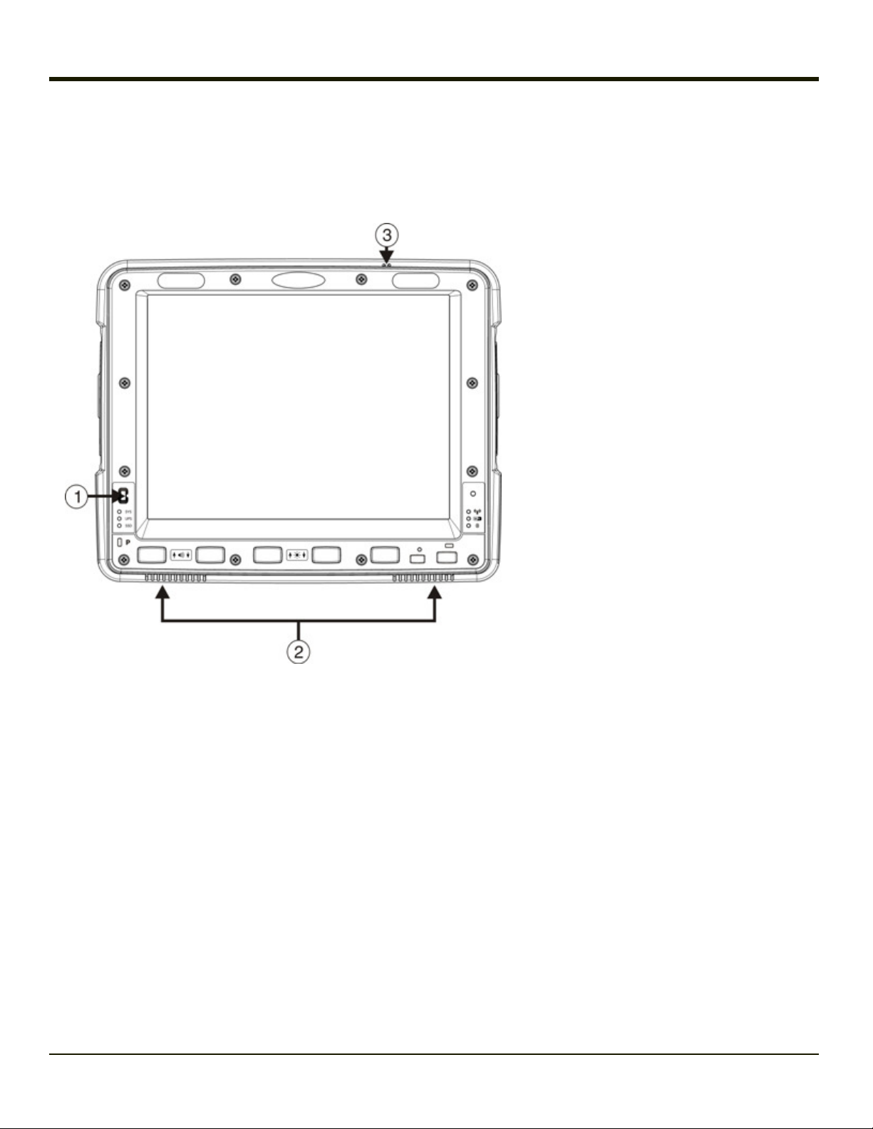
Front View
1. Power Button
2. Speakers
3. Microphone
1-2
Rev. (a)
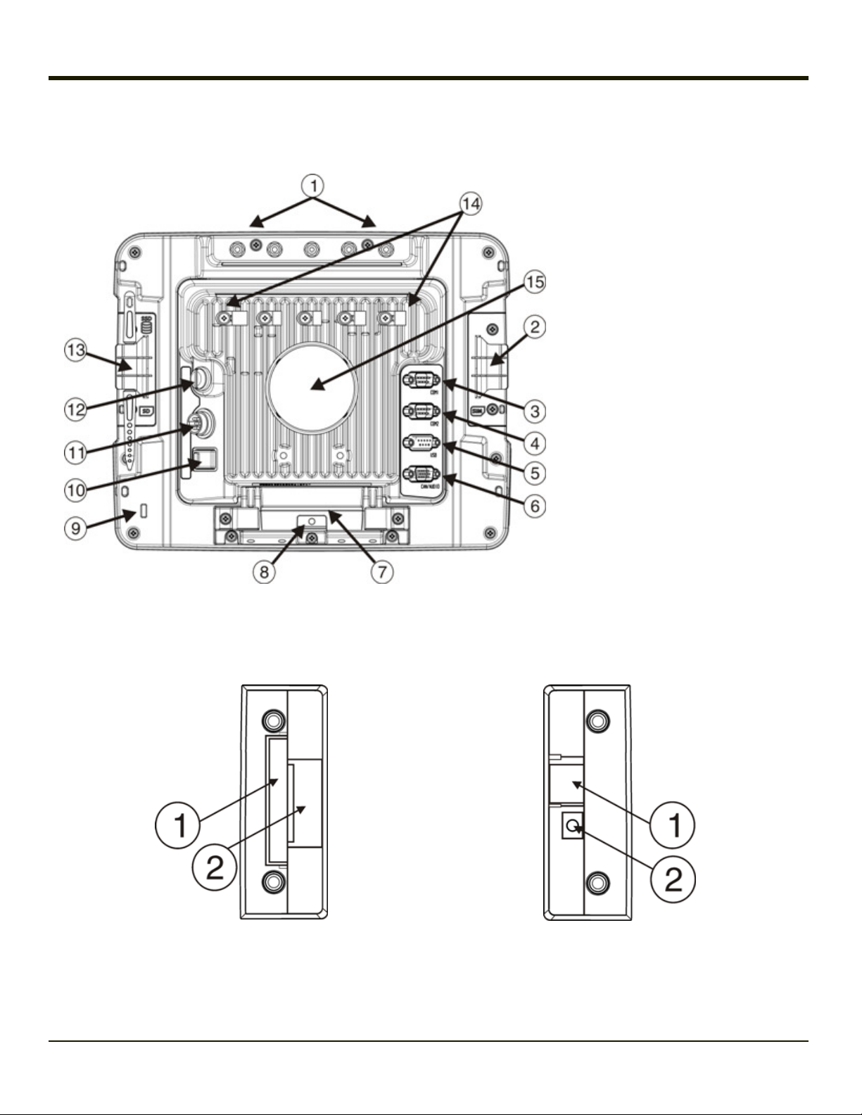
Back View Quick Mount Smart Dock
1. Antenna Connectors (on Thor
VM2WG)
2. SIM card Access Panel (on Thor
VM2WG)
3. COM1 Connector (on Dock)
4. COM2 Connector (on Dock)
5. USB Connector (on Dock)
6. CAN/Audio Connector (on Dock)
7. Quick Release Handle (On Thor
VM2WG)
8. Provision for Padlock (on Thor
VM2WG)
9. Provision for Laptop Security Cable
(on Thor VM2WG)
10. Power Switch (on Dock)
11. Power Connector (on Dock)
12. Fuse (on Dock)
13. SD Card Access Panel (On Thor
VM2WG)
14. Strain Relief Clamps (on Dock)
15. RAM Ball (on Dock)
Access Panels
Access Panel Door is labeled with SSD and SD.
1. CompactFlash Hard Drive
2. SD (Secure Digital) Memory Card Slot
Access Panel Door is labeled with SIM.
1. SIM card slot for WWAN radio
2. UPS battery disconnect
1-3
Rev. (a)
Keyboard Options
The Thor VM2WG has an integrated keypad with five programmable keys and an available external keyboard.
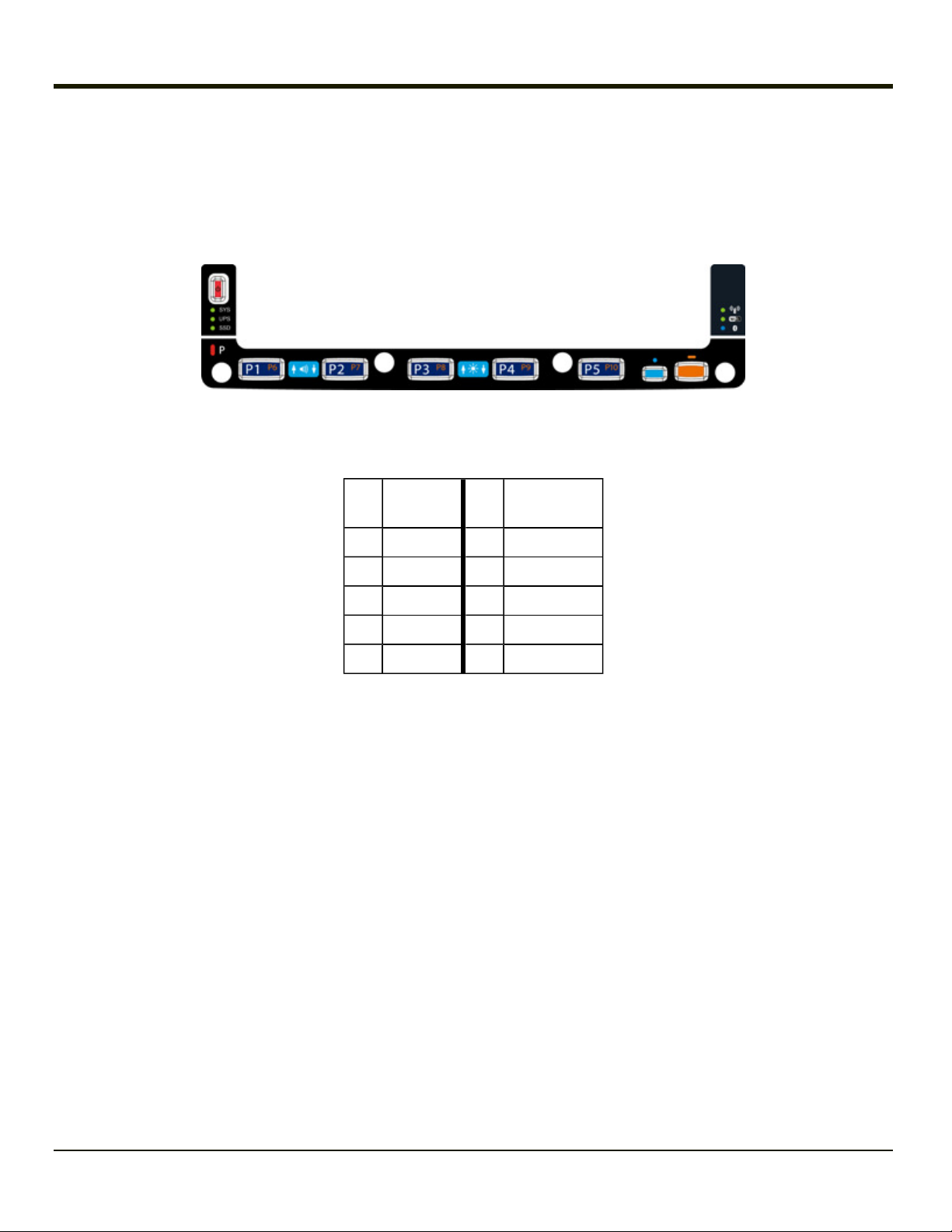
Integrated Keypad
The integrated keypad contains five progammable keys, a blue modifier key and an orange modifier key. Press Orange plus
P1-P5 to access P6-P10. The default programmable key functions are described below. Default functions may be overridden
by custom settings. Consult your system administrator.
Key
Assigned
Function
Key
Assigned
Function
P1 F1 P6 Not assigned
P2 F2 P7 Not assigned
P3 F3 P8 Not assigned
P4 F4 P9 Not assigned
P5 F5 P10 Not assigned
Blue Key
When the Blue LEDis illuminated, the programmable keys are used to adjust speaker volume and display brightness. Press
the Blue key to enter Blue mode and then press
l P1 to Increase speaker volume
l P2 to Decrease speaker volume
l P3 to Increase display brightness
l P4 to Decrease display brightness
l No function is assigned to P5 in Blue mode
The Blue key has a five second timeout. If the Blue key is pressed and no additional key is pressed within the five second
timeout period, the Blue modifier mode is exited and the Blue LEDis turned off.
When the Blue modifier key is active, the LED located next to the key is illuminated. The modifier key remains active until:
l The Blue modifier key is pressed again, or
l The Orange modifier key is pressed, or
l A five second timeout with no keypress occurs.
1-4

Rev. (a)
Orange Key
When the Orange LED is illuminated, the programmable keys provide the secondary function.
l Orange + P1 = P6
l Orange + P2 = P7, etc.
When the Orange modifier key is active, the LED located next to the key is illuminated. The modifier key remains active until:
l The Orange modifier key is pressed again, or
l A non-modifier key is pressed (i.e.: P1-P5), or
l The Blue modifier key is pressed.
1-5

Rev. (a)
95-Key External Keyboard
The Thor VM2WG uses an optional rugged QWERTY 95 key keyboard, designed for ease of use with the Windows CE
operating system. The keyboard connects directly to the D9 USB connector on the Thor VM2WG Quick Mount Smart Dock.
l The 95 key keyboard supports all 104 keyboard functions (101 standard keyboard plus Windows keys) and includes an
integrated pointing device and left and right mouse buttons. However, because the keyboard only has 95 keys, all
functions are not visible (or printed on the keyboard). Therefore the keyboard supports what is called hidden keys - keys
that are accessible but not visible on the keyboard.
l The 95 key keyboard keys are backlit. The keyboard backlight is manually controlled.
Keyboard Backlight
The keyboard backlight key in the top right hand corner has a light bulb icon.
The keyboard keys are backlit. The keyboard backlight is manually controlled using the backlight key in the upper right hand
corner of the keyboard. Pressing the backlight key cycles the keyboard backlight through the levels of backlight intensity: Off,
Low intensity, Medium intensity, Maximum intensity, Off, etc. When the Thor VM2WG is powered on, the keyboard backlight
defaults to Off.
By default, the external keypad backlight turns off when the Thor VM2WG enters Standby.
USB Keyboard / Mouse
A standard USB keyboard or mouse can be attached to the Thor VM2WG using the appropriate dongle cable.
The dongle cable attaches to the Thor VM2WG and provides a USB connector. Please refer to documentation provided with
the USB keyboard or mouse for more information on their operation.
1-6

Chapter 2 - Set Up A New Thor VM2WG
This page lists a quick outline of the steps you might take when setting up a new Thor VM2WG. More instruction for each step
is listed later in this guide. Please refer to the Thor VM2WGReference Guide for additional information and instruction.
Contact
Note: Installing or removing accessories should be performed on a clean, well-lit surface. When necessary, protect the work
Technical Assistance if you need additional help.
surface, the Thor VM2WG, and components from electrostatic discharge.
Caution
Before shipping, the internal UPS battery must be disconnected.
Please refer to the Thor VM2WG Reference Guide for details.
Hardware Setup
1. Connect accessories to the
2. Connect cables.
3. Connect power cable to the dock.
4. Secure all cables to the dock with the Strain Relief Cable Clamps.
5. Secure the Thor VM2WG in the dock.
6. Press the power switch on the dock.
7. Press the Power key.
Quick Mount Smart Dock.
Software Setup
Hardware setup should be completed before starting software setup.
1. Set Date and Time
2. Set Power Management
3. Adjust Speaker Volume
4. Pair Bluetooth devices
5. Setup Wireless client parameters - Please refer to the Thor VM2WG Reference Guide
6. Setup terminal emulation parameters
Please refer to the Thor VM2WGReference Guide for additional information and instruction.
2-1

Rev. (a)
Quick Mount Smart Dock
The Thor VM2WG assembly consists of two parts, the Thor VM2WG computer and the Quick Mount Smart Dock.
The Thor VM2WG contains an internal UPS battery that, once fully charged, powers the Thor VM2WG for a minimum of 30
minutes when the unit is not mounted in the dock.
The Dock provides:
l A mount for the Thor VM2WG computer. The Dock attaches to a vehicle via a RAM or U-bracket mount.
l Conditioned power for the Thor VM2WG. The Dock accepts 10-60VDC power input directly or 72-144VDC power input
with a DC/DC converter.
l COM1 and COM2 serial connections for a tethered scanner, printer, PC connection, etc.
l USB host and client connections via an adapter cable.
l CANbus connection via an adapter cable.
l Headset connection via an adapter cable. When a headset is not attached, the microphone and speakers on the Thor
VM2WG are active.
l Strain relief cable mounts.
l Mobility of the Thor VM2WG, since the Dock remains attached to the vehicle the Thor VM2WG computer can easily be
moved from one vehicle equipped with a Dock to another.
External antenna connectors may be present on the back of the Thor VM2WG. The connectors may include:
l 802.11 antenna connectors, used when the Thor VM2WG is not equipped with internal antennas.
l External GPS antenna connector, when the Thor VM2WG is equipped with GPS.
l External WWAN antenna connectors, when the Thor VM2WG is equipped with WWAN.
Optional WWAN radio (available in North America, Europe, New Zealand,and Australia only).
2-2
Rev. (a)
Preparing the Dock
1. Attach RAM mount to vehicle (see Thor VM2WG Vehicle Mounting Reference Guide).
Attach accessories to dock.
2.
3. Attach power cable, 10-60VDC or 72-144VDC.
4. If the tethered I/O port cover is in place, lift the cover to expose the I/O port on the dock. The tether allows the cover to
be swung over the back of the dock.
2-3
Rev. (a)
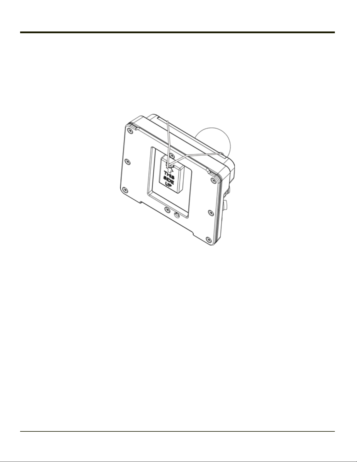
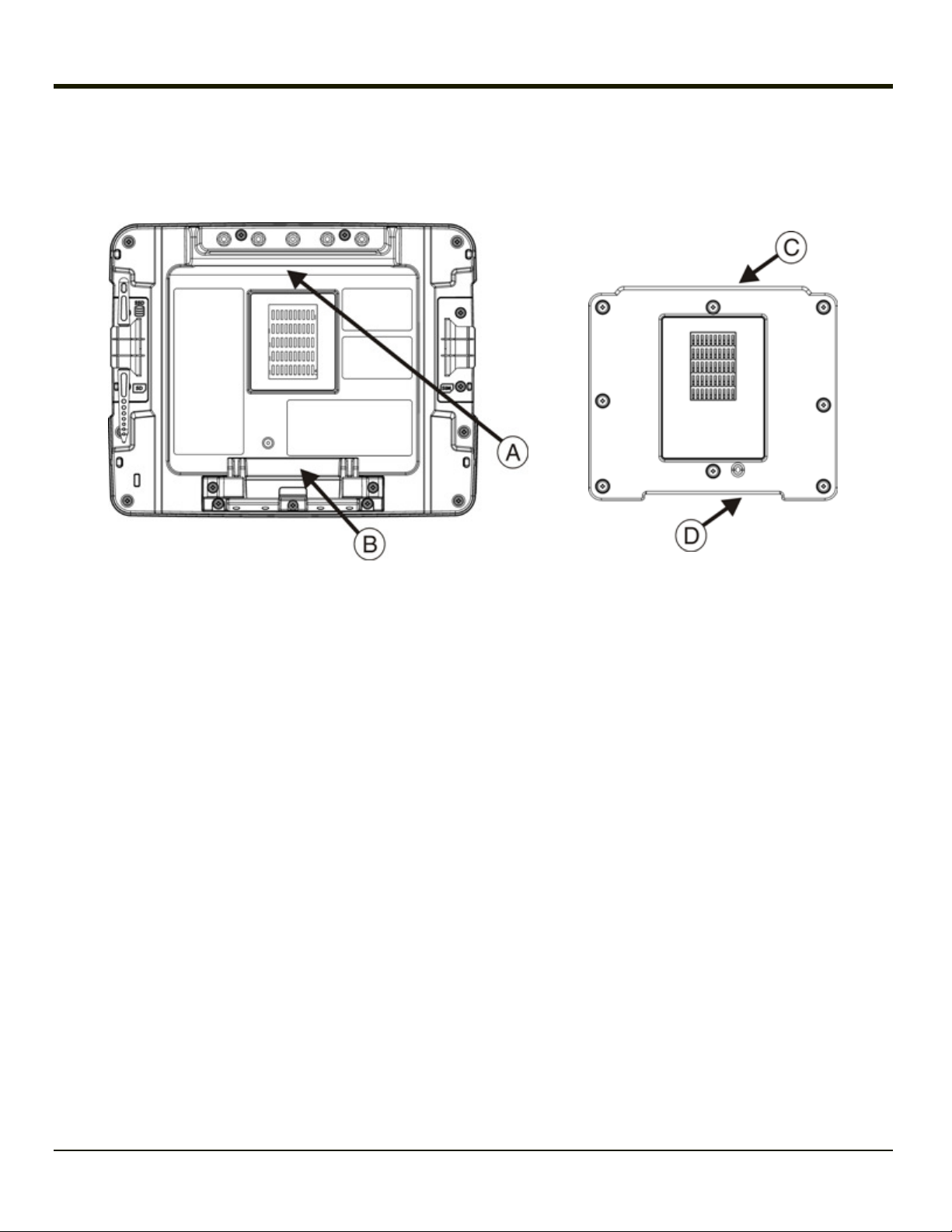
Place the Thor VM2WG in the Dock
Back of Thor VM2WG Front of Quick Mount Smart Dock
A. Notch on Thor VM2WG
B. Release lever
1. Locate the notch on the upper rear of the Thor VM2WG (item A above).
2. Slide this notch over the top lip (C)of the Dock. Slide the Thor VM2WG from side to side on the Dock to make sure it
fully engages on the lip of the Dock. If the Thor VM2WG cannot be slid side to side, the lip is engaged.
3. Pull the quick release lever (B) on the Thor VM2WG down and push the Thor VM2WG against the Dock.
4. Release the quick release lever. The quick release lever catches the lower lip on the Dock and secures the Thor
VM2WG to the Dock.
5. If necessary, adjust the viewing angle of the Thor VM2WG.
C. Upper Lip on Dock
D. Lower Lip on Dock
Removing the Thor VM2WG from the Dock
The Thor VM2WG may be removed from the Quick Mount for limited periods of use or the transfer from vehicle to vehicle.
The UPS battery inside the Thor VM2WG powers a fully functional Thor VM2WG for a minimum of 30 minutes.
To remove the Thor VM2WG from the Dock:
1. Pull the quick release lever (item B) downward on the back of the Thor VM2WG.
2. Pull the bottom of the Thor VM2WG away from the Dock.
3. Lift the Thor VM2WG away from the Dock.
2-4

Rev. (a)
Backlights and Indicators
Display Backlight
There are several configuration options for the Thor VM2WG display backlight:
Power Management
The display backlight is controlled by power management. When the user activity timer expires, the display backlight is turned
off. Different timeouts can be set for when the Thor VM2WG is operating in the following power management schemes:
l AC/DC
l Ignition Control (ignition on)
l Ignition Control (ignition off)
l Auto-On
l UPS.
Timeouts can be specified for each scheme when operating on external power (plugged in) and when on UPS power (running
on batteries).
Please refer to the Thor VM2WG Reference Guide for details.
The display backlight can be configured using this option:
Start > Control Panel > Power.
Backlight Brightness
The intensity of the display backlight can be manually configured:
l Press the Blue key to enter Blue mode
l Press the P3 key to increase backlight brightness or the P4 key to decrease backlight brightness.
l Press the Blue key to exit Blue mode.
Please refer to the Screen Control panel in the Thor VM2WG Reference Guide for the current display brightness level.
Screen Blanking
The Thor VM2WG can be configured to blank (blackout) the display while the vehicle is in motion.
Please refer to the Screen Control panel in the Thor VM2WG Reference Guide for details.
Keypad Backlight
By default, the integrated keypad backlight follows the display backlight. The integrated keypad backlight can be disabled.
The external USB keyboard backlight is manually controlled.
2-5
Rev. (a)
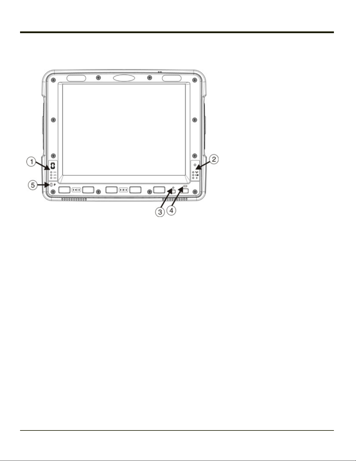
LED Functions
1. System LEDs
2. Connection LEDs
3. Blue LED
4. Orange LED
5. Programmable LED
2-6
Rev. (a)
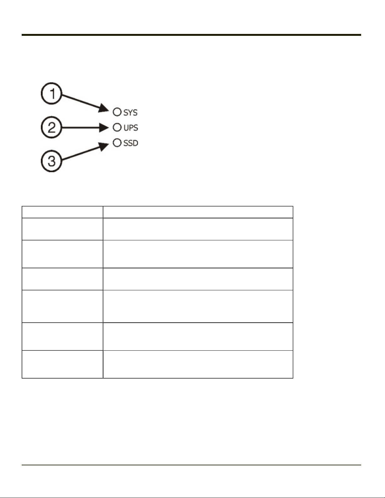
System LEDs
SYS (System Status) LED
1. SYS (System Status) LED
2. UPS (Uninterruptible Power Supply) LED
3. SSD (Solid State Drive) LED
LED Behavior System State
Solid Green
l On
l On but Display Off
Green blinking very slowly
External power present
l Standby
(1/2 sec. on, 4 1/2 sec. off)
Off
External power present
Off
External power not present
Green blinking slowly
External power present
(1/2 sec. on, 1 1/2 sec. off)
Green blinking slowly
External power not present
(1/2 sec. on, 1 1/2 sec. off)
l Off
l Hibernate
l Off,
l Hibernate
l Standby
CPU temperature less than -20ºC,
Heater warming CPU for 30 sec.
CPU temperature less than -20ºC,
Need to move unit to warmer environment
2-7

Rev. (a)
UPS Status LED
The color of the UPS LED identifies the charge level and the behavior of the LED identifies the charging state.
Charge Level
LED Color
Status
Green Fully charged (>90%)
l Less than fully charged, but more than 2 minutes runtime
remaining,
Amber
l Out of charging temperature range,
l No UPS present,
l Charge timeout.
Red Low battery, less than 2 minutes runtime until shutdown
Charging State
LED Behavior
Slow Blink
(1 sec. on, 3 sec. off)
Fast Blink
(1/2 sec. on, 1/2 sec. off)
Charging.
UPS supplying power and discharging.
On Neither charging or discharging.
Off Unit is off or is in Standby or Hiberbate.
Status
SSD (Solid State Drive) LED
LED Behavior
Flashing Green SSD read or write activity.
Off No SSD read or write activity.
2-8
Status
 Loading...