

Page 1

Thor™ VM1
Vehicle-Mounted Computer
Microsoft®Windows®Embedded CE 6 Operating System
Reference Guide
Page 2

Disclaimer
Honeywell International Inc. (“HII”) reserves the right to make changes in specifications and other information contained in this
document without prior notice, and the reader should in all cases consult HII to determine whether any such changes have
been made. The information in this publication does not represent a commitment on the part of HII.
HII shall not be liable for technical or editorial errors or omissions contained herein; nor for incidental or consequential damages
resulting from the furnishing, performance, or use of this material.
This document contains proprietary information that is protected by copyright. All rights are reserved. No part of this document
may be photocopied, reproduced, or translated into another language without the prior written consent of HII.
© 2011-2012 Honeywell International Inc. All rights reserved.
Web Address: www.honeywellaidc.com
RFTerm is a trademark or registered trademark of EMS Technologies, Inc. in the United States and/or other countries.
Microsoft®Windows, ActiveSync®, MSN, Outlook®, Windows Mobile®, the Windows logo, and Windows Media are
registered trademarks or trademarks of Microsoft Corporation.
Intel®and Atom™ are trademarks or registered trademarks of Intel Corporation or its subsidiaries in the United States and
other countries.
Summit Data Communications, the Laird Technologies Logo, the Summit logo, and "Connected. No Matter What" are
trademarks of Laird Technologies, Inc.
The Bluetooth®word mark and logos are owned by the Bluetooth SIG, Inc.
Symbol®is a registered trademark of Symbol Technologies. MOTOROLA, MOTO, MOTOROLA SOLUTIONS and the
Stylized M Logo are trademarks or registered trademarks of Motorola Trademark Holdings, LLC and are used under license.
Wavelink®, the Wavelink logo and tagline, Wavelink Studio™, Avalanche Management Console™, Mobile Manager™, and
Mobile Manager Enterprise™ are trademarks of Wavelink Corporation, Kirkland.
RAM®and RAM Mount™ are both trademarks of National Products Inc., 1205 S. Orr Street, Seattle, WA 98108.
Qualcomm®is a registered trademark of Qualcomm Incorporated. Gobi is a trademark of Qualcomm Incorporated.
Verizon®is a registered trademark of Verizon Trademark Services LLC.
T-MOBILE®is a registered trademark of Deutsche Telekom AG.
AT&T®is a registered trademark of AT&T Intellectual Property.
Acrobat®Reader © 2012with express permission from Adobe Systems Incorporated.
Other product names or marks mentioned in this document may be trademarks or registered trademarks of other companies
and are the property of their respective owners.
Patents
For patent information, please refer to www.honeywellaidc.com/patents.
Limited Warranty
Refer to www.honeywellaidc.com/warranty_information for your product’s warranty information.
Page 3

Table of Contents
Chapter 1: Introduction 1-1
About this Guide 1-1
End User License Agreement (EULA) 1-2
Components 1-3
Front View 1-3
Back View with Quick Mount Smart Dock 1-4
Access Panels 1-4
Chapter 2: Hardware 2-1
System Hardware 2-1
802.11a/b/g Wireless Client 2-1
Central Processing Unit 2-1
Input/Output Components 2-2
System Memory 2-2
Video Subsystem 2-2
Audio Interface 2-2
Card Slots 2-2
CompactFlash (CF) Slot 2-2
Secure Digital (SD) Slot 2-2
Bluetooth LXEZ Pair 2-3
WWAN 2-3
GPS 2-3
Power 2-4
Vehicle DC Power Supply 2-4
External AC Power Supply 2-4
Uninterruptible Power Supply 2-4
Backup Battery 2-5
Fuse 2-5
Power Management Modes 2-6
On Mode (D0) 2-6
User Idle / Backlight Off Mode (D1) 2-6
System Idle / Display Off Mode (D2) 2-6
Suspend mode (D3) 2-6
Shutdown / Off Mode (D4) 2-6
Primary Events 2-7
User Primary Events 2-7
System Primary Events 2-7
Wake Source Events 2-7
i
Page 4

Power Controls 2-9
Power Switch 2-9
Thor VM1 Power Button 2-9
Vehicle Ignition Monitoring 2-10
Auto On Behavior 2-10
Auto-On Enabled 2-10
Auto-On Disabled 2-10
External Connectors 2-11
Serial Connector (COM1 and COM2) 2-12
Pinout 2-12
Screen Blanking 2-13
Serial Cable 2-13
Screen Blanking Box 2-14
Screen Blanking with Switch 2-14
USB Connector 2-15
USB Dongle Cable 2-16
D9 Male Connector 2-16
USB Host Connector 2-17
USB Client Connector 2-17
Power Supply Connector 2-18
CANbus / Audio Connector 2-19
Headset Adapter Cable 2-20
D15 Female Connector 2-20
Quick Connect Headset Connector 2-21
CANbus Cable 2-22
D15 Female Connector 2-22
9-Pin J1939 (Deutsch) Connectors 2-23
Antenna Connections 2-24
Antenna Connector 2-24
Internal WiFi Antenna 2-24
Vehicle Remote Antenna 2-24
Keyboard Options 2-25
64-Key QWERTY Keyboard 2-25
IBM 3270 Overlay 2-26
IBM 5250 Overlay 2-27
12-Key Keyboard 2-28
Keyboard LEDs 2-29
Shift LEDs 2-29
Secondary Keys LED 2-29
Ctrl and Alt Key LEDs 2-29
ii
Page 5

USB Keyboard / Mouse 2-29
LED Functions 2-30
System LEDs 2-31
SYS (System Status) LED 2-31
UPS Status LED 2-32
External Power Present 2-32
External Power Not Present 2-32
SSD (Solid State Drive) LED 2-32
Connection LEDs 2-33
WWAN LED 2-33
WiFi LED 2-33
Bluetooth LED 2-33
Keyboard LEDs 2-34
2nd LED 2-34
Shift LEDs 2-34
Ctrl LED 2-34
Alt LED 2-35
Display 2-36
Touch Screen 2-36
Touch Screen Defroster 2-36
Screen Blanking 2-36
Display Backlight Control 2-36
Disconnect UPS Battery 2-37
Install SD Card 2-39
Install SIM Card 2-41
Field Replaceable Front Panel 2-43
Replace Front Panel 2-43
Field Replaceable UPS Battery 2-45
Replace UPS Battery 2-45
Chapter 3: Software 3-1
Introduction 3-1
Operating System 3-1
Windows CE Operating System 3-1
General Windows CE Keyboard Shortcuts 3-2
Rebooting the Thor VM1 3-3
Warmboot 3-3
Restart 3-3
Clearing Persistent Storage / Reset to Default Settings 3-3
Folders Copied at Startup 3-3
iii
Page 6

Saving Changes to the Registry 3-4
Software Load 3-5
Software Applications 3-5
ActiveSync 3-5
Bluetooth 3-5
LXE RFTerm (Optional) 3-6
Avalanche 3-6
Software Development 3-6
Thor VM1 Utilities 3-6
LAUNCH.EXE 3-6
LAUNCH.EXE and Persistent Storage 3-7
REGEDIT.EXE 3-8
REGLOAD.EXE 3-8
REGDUMP.EXE 3-8
WARMBOOT.EXE 3-8
WAVPLAY.EXE 3-8
Thor VM1 Command-line Utilities 3-8
PrtScrn.EXE 3-8
Desktop 3-9
Desktop Icons 3-9
Taskbar 3-10
My Device Folders 3-10
Wavelink Avalanche Enabler (Optional) 3-11
Internet Explorer 3-11
Start Menu Program Options 3-12
Communication 3-12
ActiveSync 3-12
Connect and LXEConnect 3-13
Start FTP Server / Stop FTP Server 3-13
Summit 3-13
Certs 3-13
Command Prompt 3-14
eXpress Scan 3-14
Internet Explorer 3-14
Media Player 3-14
File Viewers 3-15
Microsoft WordPad 3-15
Remote Desktop Connection 3-15
Settings 3-15
Transcriber 3-15
iv
Page 7

Windows Explorer 3-16
Taskbar 3-17
General Tab 3-17
Advanced Tab 3-17
Expand Control Panel 3-17
Clear Contents of Document Folder 3-18
Taskbar Icons 3-18
Thor VM1 OS Upgrade 3-19
Introduction 3-19
Preparation 3-19
Procedure 3-19
BIOS 3-20
Accessing the BIOS Setup 3-20
Boot Order 3-20
Exiting BIOS Setup 3-20
Control Panel 3-21
About 3-23
Version Tab and the Registry 3-23
Languages 3-23
Identifying Software Versions 3-24
MAC Address 3-24
Accessibility 3-25
Administration (for AppLock) 3-26
Factory Default Settings - AppLock 3-27
Setup a New Device 3-28
Administration Mode 3-28
End User Mode 3-29
Passwords 3-29
End-User Switching Technique 3-30
Using a Stylus Tap 3-30
Using the Switch Key Sequence 3-30
Hotkey (Activation hotkey) 3-31
Application Configuration 3-32
Application Panel 3-33
Launch Button 3-35
Auto At Boot 3-36
Auto Re-Launch 3-37
Manual (Launch) 3-38
Allow Close 3-38
End User Internet Explorer (EUIE) 3-39
v
Page 8

Security Panel 3-40
Options Panel 3-41
Status Panel 3-42
View 3-42
Log 3-43
Save As 3-43
AppLock Help 3-44
AppLock Error Messages 3-44
Battery 3-52
Bluetooth 3-53
Bluetooth Devices 3-54
Discover 3-55
Stop Button 3-55
Bluetooth Device List 3-56
Clear Button 3-56
Bluetooth Device Menu 3-57
Right-Click Menu Options 3-57
Bluetooth Device Properties 3-58
Settings 3-59
Turn Off Bluetooth 3-59
Options 3-60
Reconnect 3-61
Options 3-62
About 3-64
Using Bluetooth 3-65
Initial Configuration 3-65
Subsequent Use 3-66
Bluetooth Indicators 3-67
Bluetooth Bar Code Reader Setup 3-68
Thor VM1 with Label 3-68
Thor VM1 without Label 3-69
Bluetooth Beep and LED Indications 3-70
Bluetooth Printer Setup 3-70
Easy Pairing and Auto-Reconnect 3-71
Certificates 3-72
Data Collection Wedge Introduction 3-73
Bar Code Readers 3-74
Return to Factory Default Settings 3-74
Data Processing Overview 3-75
Factory Default Settings 3-76
vi
Page 9

Main Tab 3-77
COM1 Tab 3-78
Power on Pin 9 3-78
COM2 Tab 3-79
Power on Pin 9 3-79
Data Options Tab 3-80
Enable Code ID 3-80
Buttons 3-81
Data Options - Symbology Settings 3-82
Clear Button 3-83
Enable, Min, Max 3-84
Strip Leading/Trailing Control 3-85
Bar Code Data Match List 3-86
Bar Code Data Match Edit Buttons 3-86
Match List Rules 3-87
Add Prefix/Suffix Control 3-88
Symbologies 3-88
Ctrl Char Mapping 3-89
Translate All 3-89
Parameters 3-89
Translate All 3-89
Character 3-90
Replacement 3-90
List Box 3-90
Assign Button 3-90
Delete Button 3-90
Custom Identifiers 3-91
Parameters 3-91
Buttons 3-92
Control Code Replacement Examples 3-93
Bar Code Processing Examples 3-94
Processing Tab 3-95
About Tab 3-96
Length Based Bar Code Stripping 3-97
Hat Encoding 3-99
Date / Time 3-101
Dialing 3-102
Display 3-103
Background 3-103
Appearance 3-104
vii
Page 10

Backlight 3-104
Gobi Connection Manager 3-105
Initial Use 3-105
SIM Card Installation 3-105
Activate 3-106
Home 3-107
CDMA 3-108
Activation Type 3-108
Autoconnect 3-109
Data Connection Test 3-109
UTMS 3-110
Autoconnect 3-110
Data Connection Test 3-110
GPS 3-110
About 3-112
Input Panel 3-113
Transcriber 3-113
Internet Options 3-114
Keyboard 3-117
KeyPad 3-118
KeyMap Tab 3-119
Remap a Single Key 3-119
Remap a Key to a Unicode Value 3-119
Remap a Key Sequence 3-120
Remap a Key to a Sequence of Unicode Values 3-120
Remap an Application 3-120
Remap a Command 3-121
LaunchApp Tab 3-122
RunCmd Tab 3-123
License Viewer 3-124
Mixer 3-125
Output Panel 3-125
Input Panel 3-126
Mouse 3-127
Network and Dialup Options 3-128
Create a New Connection 3-128
Network Capture 3-129
Netlog 3-129
NDISLog 3-131
Options 3-132
viii
Page 11

Communication 3-133
Enable TCP/IP Version 6 3-133
Allow Remote Desktop Autologon 3-133
Autolaunch TimeSync 3-133
Misc 3-134
CapsLock 3-134
Touch Screen Disable 3-134
Enable Keypad Backlight 3-134
Enable Auto-On 3-134
Status Popup 3-135
Owner 3-136
Password 3-138
PC Connection 3-139
Peripherals 3-140
Power 3-141
Regional and Language Settings 3-143
Registry 3-145
Remove Programs 3-146
Screen Control 3-147
Screen Blanking 3-149
Current Level 3-149
Automatic Brightness Control 3-149
Stylus 3-150
Double-Tap 3-150
Calibration 3-150
System 3-151
General Tab 3-151
Memory Tab 3-152
Device Name Tab 3-152
Copyrights Tab 3-153
Terminal Server Client Licenses 3-154
Volume and Sounds 3-155
Good Scan and Bad Scan Sounds 3-156
WiFi Control Panel 3-157
Chapter 4: ActiveSync 4-1
Introduction 4-1
Initial Setup 4-2
Connect via USB 4-2
Cable for USB ActiveSync Connection: 4-2
ix
Page 12

Explore 4-3
Backup Data Files using ActiveSync 4-3
Prerequisites 4-3
Connect 4-3
Disconnect 4-4
Thor VM1 with a Disabled Touch Screen 4-4
Reset and Loss of Host Re-connection 4-4
Troubleshooting ActiveSync 4-5
Configuring the Thor VM1 with LXEConnect 4-6
Install LXEConnect 4-6
Using LXEConnect 4-7
Chapter 5: Enabler Installation and Configuration 5-1
Introduction 5-1
Installation 5-1
Installing the Enabler on Mobile Devices 5-1
Enabler Uninstall Process 5-2
Stop the Enabler Service 5-2
Update Monitoring Overview 5-3
Mobile Device Wireless and Network Settings 5-4
Preparing a Device for Remote Management 5-5
Using Wavelink Avalanche to Upgrade System Baseline 5-6
Part 1 – Bootstrapping the RMU 5-6
Part 2 – Installing Packages 5-6
Version Information on Mobile Devices 5-6
User Interface 5-7
Enabler Configuration 5-7
File Menu Options 5-8
Avalanche Update using File > Settings 5-9
Menu Options 5-9
Connection 5-10
Server Contact 5-11
Data 5-12
Preferences 5-13
Display 5-15
Taskbar 5-16
Execution 5-17
Scan Config 5-18
Shortcuts 5-19
SaaS 5-20
x
Page 13

Adapters 5-21
Status 5-24
Exit 5-25
Using Remote Management 5-25
Using eXpress Scan 5-26
Step 1: Create Bar Codes 5-26
Step 2: Scan Bar Codes 5-26
Step 3: Process Completion 5-28
Chapter 6: Wireless Network Connections 6-1
Summit Wireless Network Configuration 6-1
Important Notes 6-1
Summit Client Utility 6-2
Help 6-2
Summit Tray Icon 6-2
Wireless Zero Config Utility and the Summit Radio 6-3
How To: Use the Wireless Zero Config Utility 6-3
How to: Switch Control to SCU 6-3
Main Tab 6-4
Auto Profile 6-5
Admin Login 6-5
Profile Tab 6-7
Buttons 6-8
Profile Parameters 6-9
Status Tab 6-11
Diags Tab 6-12
Global Tab 6-13
Custom Parameter Option 6-14
Global Parameters 6-15
Sign-On vs. Stored Credentials 6-19
How to: Use Stored Credentials 6-19
How to: Use Sign On Screen 6-19
Windows Certificate Store vs. Certs Path 6-21
User Certificates 6-21
Root CA Certificates 6-21
How To: Use the Certs Path 6-21
How To: Use Windows Certificate Store 6-21
Configuring the Profile 6-23
No Security 6-24
WEP 6-25
xi
Page 14

LEAP 6-26
PEAP/MSCHAP 6-27
PEAP/GTC 6-29
WPA/LEAP 6-31
EAP-FAST 6-33
EAP-TLS 6-35
WPA PSK 6-37
Certificates 6-38
Generating a Root CA Certificate 6-39
Installing a Root CA Certificate 6-42
Generating a User Certificate 6-44
Installing a User Certificate 6-50
Verify Installation 6-52
Chapter 7: Technical Specifications 7-1
Thor VM1 7-1
Quick Mount Smart Dock 7-2
Dimensions 7-2
Thor VM1 7-2
Quick Mount Smart Dock 7-2
Environmental Specifications 7-3
Thor VM1 and Quick Mount Smart Dock 7-3
Network Card Specifications 7-4
Summit 802.11a/b/g 7-4
Bluetooth 7-4
Chapter 8: Key Maps 8-1
64-Key QWERTY Keypad Key Map 8-1
12-Key Keypad Key Map 8-6
IBM Terminal Emulation 8-8
IBM 3270 8-8
IBM 5250 8-9
Chapter 9: Technical Assistance 9-1
xii
Page 15
Chapter 1: Introduction
The Thor VM1 Vehicle Mount Computer (VMC) is a rugged, vehicle mounted computer running a Microsoft®Windows®CE 6
operating system and capable of wireless data communications from a fork-lift truck or any properly configured vehicle.
Wireless communications are supported over a 802.11 WLAN network and, optionally, over a WWAN network. The optional
Bluetooth®module supports Bluetooth printers and scanners.
Caution
Before shipping the Thor VM1, the internal UPS battery must be disconnected.
The Thor VM1 is designed for use with a vehicle Quick Mount Smart Dock. The dock installs in the vehicle and connects to
vehicle power. The dock provides conditioned input power for the Thor VM1. Peripheral connections are on the dock. The Thor
VM1 is designed to easily be removed from the dock with a latch on the lower rear of the Thor VM1 housing. Since the dock
remains attached to the vehicle, the Thor VM1 computer can easily be moved from one vehicle equipped with a Quick Mount
Smart Dock to another vehicle equipped with a Quick Mount Smart Dock.
The Thor VM1 contains a UPS battery which, when fully charged, can power the Thor VM1 for a minimum of 30 minutes. This
can be when the Thor VM1 is not attached to a Quick Mount Smart Dock or when the Thor VM1 is attached to a dock but the
vehicle power is interrupted, such as when the vehicle battery is being changed.
Contact Technical Assistance for information on the latest upgrades for your Thor VM1.
About this Guide
This Thor VM1 Reference Guide provides instruction for the system administrator to follow when configuring a Thor VM1.
This reference guide has been developed for a Thor VM1 with a Microsoft®Windows®Embedded CE 6 operating system.
1-1
Page 16

End User License Agreement (EULA)
When a new Thor VM1 starts up a EULA is displayed on the touch screen. It remains on the screen until the Accept or Decline
button is tapped with a stylus.
Tap the Accept button to accept the EULA terms and the Thor VM1 continues the startup process. The EULA is not presented
to the user again.
Tap the Decline button to decline the EULA and the Thor VM1 will reboot. It will continue to reboot until the Accept button is
tapped with the stylus.
Note: The EULA will be presented after any operating system upgrade or re-installation, including language-specific
operating systems.
1-2
Page 17
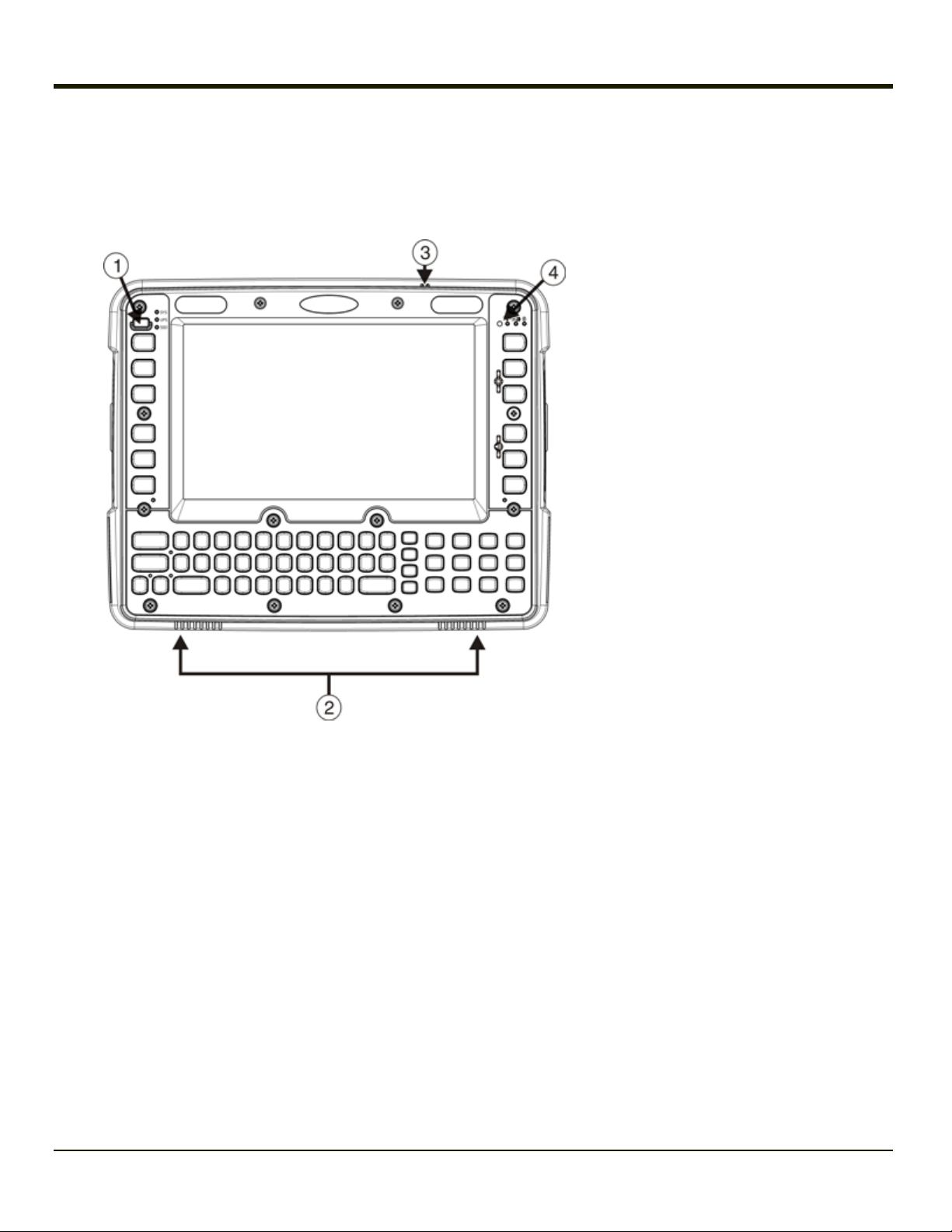
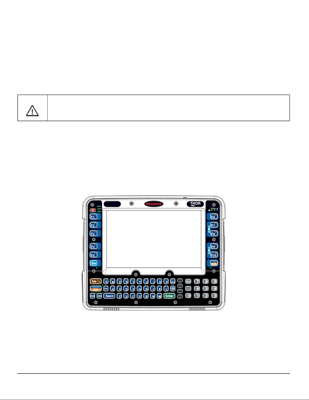
Components
Front View
1. Power Button
2. Speakers
3. Microphone
4. Ambient Light Sensor
1-3
Page 18
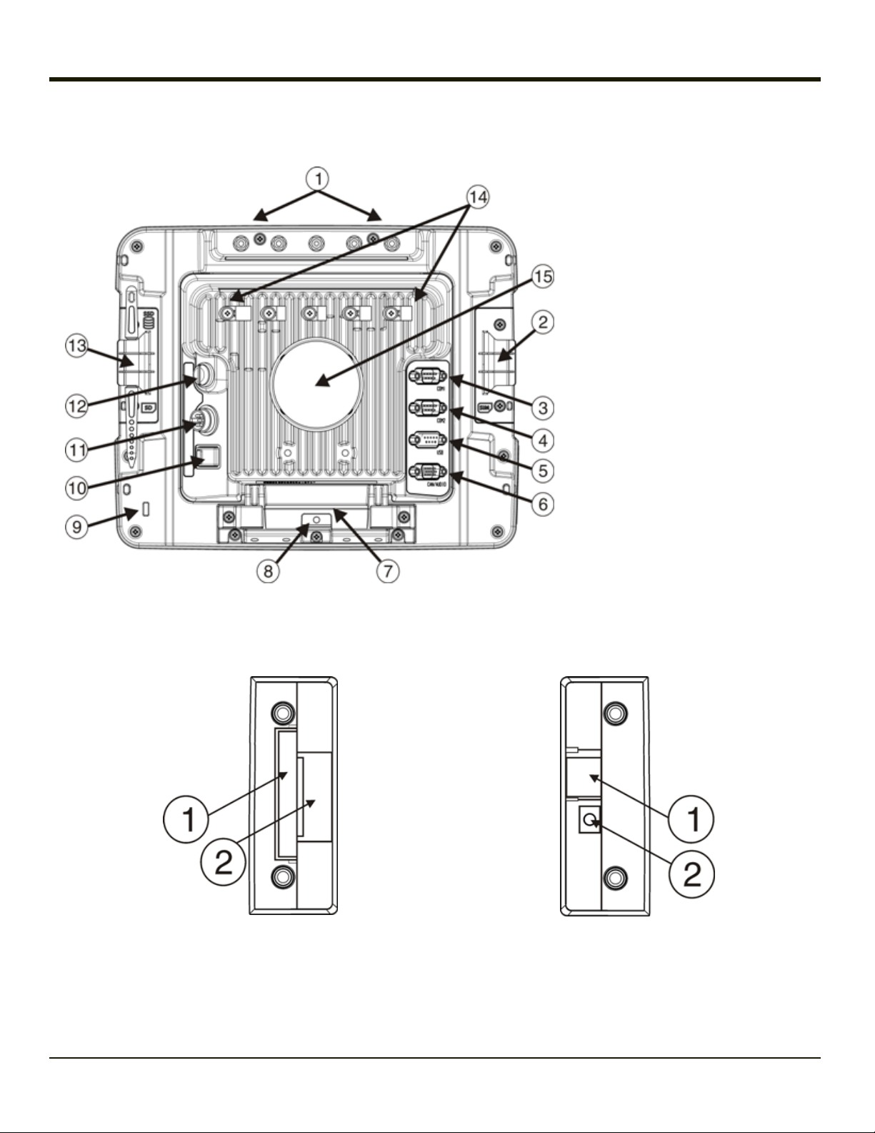
Back View with Quick Mount Smart Dock
1. Antenna Connectors (on Thor VM1)
2. SIM card Access Panel (on Thor
VM1)
3. COM1 Connector (on Dock)
4. COM2 Connector (on Dock)
5. USB Connector (on Dock)
6. CAN/Audio Connector (on Dock)
7. Quick Release Handle (On Thor
VM1)
8. Provision for Padlock (on Thor
VM1)
9. Provision for Laptop Security Cable
(on Thor VM1)
10. Power Switch (on Dock)
11. Power Connector (on Dock)
12. Fuse (on Dock)
13. SD Card Access Panel (On Thor
VM1)
14. Strain Relief Clamps (on Dock)
15. RAM Ball (on Dock)
Access Panels
Access Panel Door is labeled with SSD and SD.
1. CompactFlash Hard Drive
2. SD (Secure Digital) Memory Card Slot
Access Panel Door is labeled with SIM.
1. SIM card slot for WWAN radio
2. UPS battery disconnect
1-4
Page 19
Chapter 2: Hardware
System Hardware
802.11a/b/g Wireless Client
The Thor VM1 has an 802.11a/b/g network card that supports diversity with two internal or external antennas. Power
management for the network card is configured with the Summit Client Utility.
Central Processing Unit
The CPU is a 1.6 GHz Intel Atom processor. The operating system is Microsoft CE 6.0. The OS image is stored on an internal
CompactFlash card and is loaded into DRAM for execution.
2-1
Page 20

Input/Output Components
The Thor VM1 supports the following I/O components of the core logic:
l Two 9-pin RS-232 serial ports configured as COM1 and COM2.
l One slot for SD memory card.
l CompactFlash (CF) drive.
l Integrated keyboard.
l Ports available via dongle cable:
o
USB Host port
o
USB Client port
o
CANbus
o
Audio
System Memory
Main system memory is 1GB SDRAM.
Video Subsystem
The Thor VM1 video subsystem consists of a color TFT display. The video subsystem complies with the VESA VL bus
standard. The resolution of this display is 800 x 480 pixels. This resolution complies with the WVGA graphics industry
standard.
The display supports screen blanking to eliminate driver distraction when the vehicle is in motion.
Audio Interface
Speakers are located on the bottom front of the Thor VM1. An headset adapter cable provides a connection for headset
operation. When a headset is plugged into the adapter cable, the main speakers are disabled.
A microphone is located at the upper right of the Thor VM1 display, near the Thor VM1 emblem. When a headset is plugged into
the adapter cable, the internal microphone is disabled.
Card Slots
CompactFlash (CF) Slot
The CF ATA slot is not hot swappable. The Thor VM1 must be powered down to insert or remove an ATA card. Since the
operating system is stored on the CF ATA card, the Thor VM1 cannot operate without the ATA card.
Secure Digital (SD) Slot
The SD slot accepts an SD memory card. The SD card is hot swappable.
2-2
Page 21

Bluetooth LXEZ Pair
The Thor VM1 contains Bluetooth version 2.0 with Enhanced Data Rate (EDR) up to 3.0 Mbit/s over the air. Bluetooth device
connection (or pairing) can occur at distances up to 32.8 ft (10 meters) Line of Sight. The wireless client retains wireless
connectivity while Bluetooth is active.
The user cannot select PIN authentication or encryption on connections from the Thor VM1. However, the Thor VM1 supports
authentication requests from pairing devices. If a pairing device requests authentication or encryption, the Thor VM1 displays a
prompt for the PIN or passcode. Maximum encryption is 128 bit. Encryption is based on the length of the user’s passcode.
Bluetooth simultaneously supports one printer as a slave Bluetooth device and one scanner, either as a slave or as a master
Bluetooth device.
l The LED on the Bluetooth scanner illuminates during a scanning operation.
l Bar code data captured by the Bluetooth scanner is manipulated by the settings in the Thor VM1 Data Collection control
panel applet.
l Multiple beeps may be heard during a bar code scan using a mobile Bluetooth scanner; beeps from the mobile Bluetooth
scanner as the bar code data is accepted/rejected, and other beeps from the Thor VM1 during final bar code data
manipulation.
WWAN
WWAN (Wireless Wide Area Networking) is available on the Thor VM1. A slot is provided for a SIM card.
GPS
GPS (Global Positioning System) is available on the Thor VM1.
2-3
Page 22
Power
Vehicle DC Power Supply
Vehicle power input for the Thor VM1 dock is 10V to 60V DC and is accepted without the need to perform any manual operation
within the Thor VM1 dock. The dock provides a conditioned power output for the Thor VM1. By using a specified DC-to-DC
adapter, input voltage of 72-144V DC nominal can be accepted.
If 10 to 60V DC power is not available – for example, in an office environment – an optional external Universal Input Power
Supply can be used to convert AC wall power to an appropriate DC level.
Power input is fused for protection and the fuse is externally accessible.
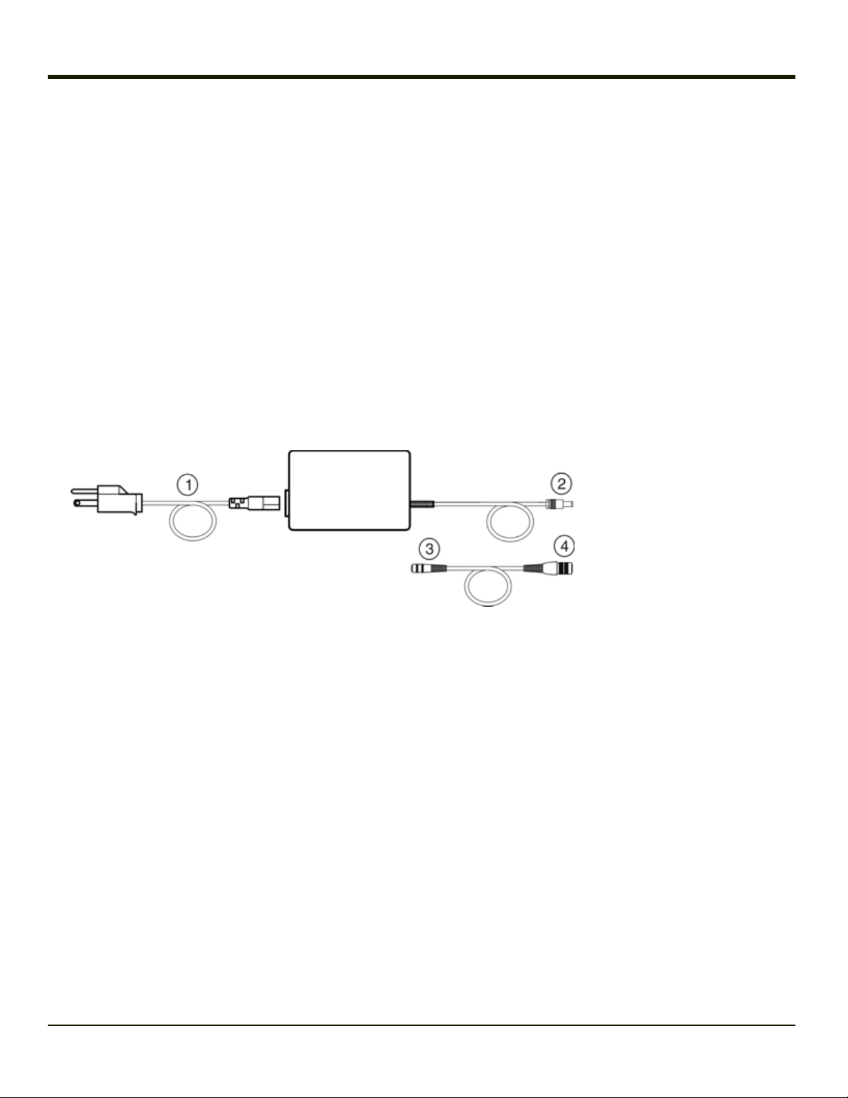
External AC Power Supply
AC to DC power input for the Thor VM1 is delivered to the Quick Mount Smart Dock via an optional external power supply and
adapter cable. One end of the adapter cable attaches to the dock and the other end is a barrel connector for the output cable
from the adapter.
1. AC Input Cable (US only)
2. DC Output Cable
3. To DC Output Cable (see
above)
4. To Thor VM1
In North America, this unit is intended for use with a UL Listed ITE power supply with output rated 12 – 48 VDC,
minimum 15 W. Outside North America, this unit is intended for use with an IEC certified ITE power supply with
output rated 12 – 48 VDC, minimum 15 W.
The external power supply may be connected to either a 120V, 60Hz supply or, outside North America, to a 230V, 50Hz
supply, using the appropriate detachable cordset. In all cases, connect the external AC supply to a properly grounded source of
supply provided with maximum 15 Amp overcurrent protection (10 Amp for 230V circuits).
Please refer to the wiring instructions, including appropriate cautions and warnings, in the Thor VM1 User Guide.
Uninterruptible Power Supply
The Thor VM1 contains an internal UPS battery.
The UPS battery is automatically charged when the Thor VM1 is placed in a powered dock.
l A fully discharged UPS battery recharges in under 4 hours when the Thor VM1 is in a powered dock.
l Charging of the UPS battery continues during power management of the Thor VM1.
l If the UPS battery is not charged before the timeout expires, the fault LEDis lit.
l If the UPS battery cannot be charged due to a temperature extreme, the fault LEDis lit. Move the Thor VM1 to a
different location to charge the UPS battery.
2-4
Page 23
When external power is removed, the UPS automatically powers the Thor VM1 with no user intervention. When running on
UPS power, the power management timeouts may be different than when vehicle power is applied.
The UPS allows the Thor VM1 to continue operation when not mounted in a dock or when the vehicle battery is being swapped.
The UPS battery is designed to power the Thor VM1 for a minimum of 30 minutes at temperatures of -20ºC (-4ºF) or greater.
For the extended temperature version of the Thor VM1, the UPS provides a minimum of 10 minutes of operation below -20ºC (4ºF), up to -30ºC (-22ºF).
If operating on UPS power and the UPS battery becomes critically low, the Thor VM1 performs a controlled shutdown.
If there is no external power available, there must be 10% or greater power in the UPS battery or the Thor VM1 does not power
on.
The UPS status LED and the Battery Control Panel can be used to monitor the state of the UPS battery.
The UPS battery can be replaced by the user.
Backup Battery
The Thor VM1 has a permanent Lithium battery installed to maintain time, date and CMOS setup information for a minimum of
90 days. The lithium battery is not user serviceable and should last five years with normal use before it requires replacement.
Note: The backup battery should only be changed by authorized service personnel.
Fuse
The Thor VM1 uses an 8A time delay (slow blow), fuse that is externally accessible and user replaceable. The fuse is located
on the back of the Quick Mount Smart Dock. The fuse is accessed by unscrewing the cap as indicated below.
Should it need replacement, replace with same size, rating and type of fuse – Littelfuse 0215008.MXP or equivalent.
Fuse has voltage on it even when power is off. Always disconnect input power before changing the fuse.
2-5
Page 24

Power Management Modes
The Thor VM1 supports the standard Microsoft Windows CE power management modes: On (D0), Backlight Off (D1), Display
Off (D2) and Suspend (D3).
On Mode (D0)
When the Thor VM1 is attached to either vehicle power or an external power supply or is operating from the UPS battery and
the power button is pressed, the Thor VM1 is in the On mode. In this mode, the keypad, touch screen and any attached
peripherals such as a scanner function normally. The display remains on until the backlight timer (if enabled) expires.
User Idle / Backlight Off Mode (D1)
Backlight is dimmed, but display is readable. The Thor VM1 transitions to this mode from On after the User Idle timeout period
has passed without a primary even occurring.
System Idle / Display Off Mode (D2)
Backlight and display are off. The status LED is solid green. The Thor VM1 transitions to this mode from User Idle after the
System Idle timeout period has passed without a primary event occurring.
Suspend mode (D3)
All devices that are not configured as wakeup events are powered off. The status LED is blinking green if external power is
connected and off if external power is not connected. The Thor VM1 transitions to this mode from System Idle after the
Suspend timeout period has passed without a primary event occurring.
Additionally the power button can be used to enter or exit Suspend mode:
l If the Thor VM1 is On, pressing the power button immediately transitions the unit to Suspend.
l If the Thor VM1 is in Suspend mode, pressing the power button transitions the unit to On.
Shutdown / Off Mode (D4)
The Thor VM1 shuts down when the Thor VM1 is operating on power and the UPS battery becomes critically low regardless of
the current power management state. The Thor VM1 remains Off until external power is applied. The Thor VM1 may restart
automatically when external power is applied or may require the user to press the Power button depending on installation and
configuration.
A Real Time Clock (RTC) powered by an internal battery maintains the date and time while the Thor VM1 is off.
2-6
Page 25

Primary Events
The Primary Events described below are the default behavior. Primary events can be modified using the
LXEPowerMgrPrimaryEvents API.
Please refer to the CE API Programming Guide for API details.
User Primary Events
A User Primary Event transitions the Thor VM1 to D0 (On) mode. When no user event happens for the specified time period,
the Thor VM1 transitions to D1 (User Idle), then D2 (System Idle) and then D3 (Suspend). Timeout periods are set via the
Schemes tab in the Power control panel.
User primary events include:
l Any key press on the keypad
l Touch on the touch screen
l USB data entry (from a USB keyboard or mouse)
System Primary Events
A System Primary Event allows the Thor VM1 to transition to D2 (System Idle) but the Thor VM1 does not enter D3 (Suspend)
as long the system event occurs.
System primary events include:
l Serial data transfer
l USB data transfer
Wake Source Events
These events wake the Thor VM1 from suspend:
l Power button
l Touch on the touch screen
l Any keypress on the keyboard
l USB connect / disconnect
l Truck power on or off (i.e. ignition key)
l RTC
l Bluetooth connection
l External power connection
l Serial port CTS control line
l Headset connection (this is not enabled by default, but can be configured to wake the Thor VM1)
Events generated by these actions are not processed. For example, the key press or touch screen tap that wakes the Thor
VM1 is ignored.
The following events DO NOT wake the Thor VM1 from suspend:
l Bluetooth keyboard or mouse
l USBhost data (unless enabled via API)
l USB host connection
2-7
Page 26

l SDIO interrupt
l Serial data
l 802.11 radio
l External power disconnect
2-8
Page 27
Power Controls
Power Switch
After all cables are connected, the Thor VM1 can be powered on.
There is a power switch located on the back of the Quick Mount Smart Dock. The power
switch is a rocker switch.
The power switch has a raised bump to identify the switch position even when it is hidden
from view. When the side of the switch with the raised bump is pressed, the power switch is
On. If the Dock is connected to external power, the Dock delivers power to the Thor VM1.
Thor VM1 Power Button
The power button is located at the bottom left of the
Thor VM1.
If the Thor VM1 is Off, pressing the power button
starts the power up sequence.
Note: This assumes that the Thor VM1 is docked
in a powered Quick Mount Smart Dock or
that the internal UPS battery has a sufficient
charge to power the Thor VM1. If no external
power is available and the UPS battery does
not have a charge, pressing the power button
causes no action.
If the Thor VM1 is On, pressing the power button
places the unit in Suspend.
2-9
Page 28

Vehicle Ignition Monitoring
When Auto-On is disabled (see below) and the ignition input wire is connected, the Thor VM1 monitors the ignition input signal
and adjusts modes as described below.
Auto On Behavior
The Thor VM1 can be configured for Auto-On using the Options control panel.
For information on the Ignition input signal please see the power cable instructions in the Thor VM1 Vehicle Mounting
Reference Guide.
Auto-On Enabled
When Auto-On is enabled, the Ignition Input signal, if connected via the Thor VM1 vehicle power supply cable, is ignored.
When Auto-On is enabled, the Thor VM1 boots when external power is applied, such as when:
l The Thor VM1 is placed in a powered Smart Dock, with the dock's power switch set to On.
l The Thor VM1 is in a Smart Dock and truck power is applied to the dock
l The Thor VM1 is in a powered Smart Dock and the dock's power switch is turned from Off to On.
If the Thor VM1 is already on and one of the above events occurs, the Thor VM1 continues to run, however the power
management scheme may change based on the connection to external power.
Auto-On Disabled
When Auto-On is disabled, the Ignition Input signal, if connected via the Thor VM1 vehicle power supply cable, is monitored.
When the Ignition Input wire is connected:
l If the Thor VM1 is Off and Ignition Input is Inactive, the Thor VM1 remains Off.
l If the Thor VM1 is Off and Ignition Input changes from Inactive to Active, the Thor VM1 boots.
l If the Thor VM1 is On and Ignition Input changes from Inactive to Active, the Thor VM1 remains On. If, for example, a
Thor VM1 is running on the UPS and is placed into a Dock connected to a truck when the truck ignition is On, the power
management scheme may change based on the availability of external power.
l If the Thor VM1 is On and Ignition Input changes from Active to Inactive, this event is treated the same as a Power
button press, which places the Thor VM1 in Suspend.
If the Ignition Input wire is not connected, the Thor VM1 only powers on when the Power button is pressed.
2-10
Page 29
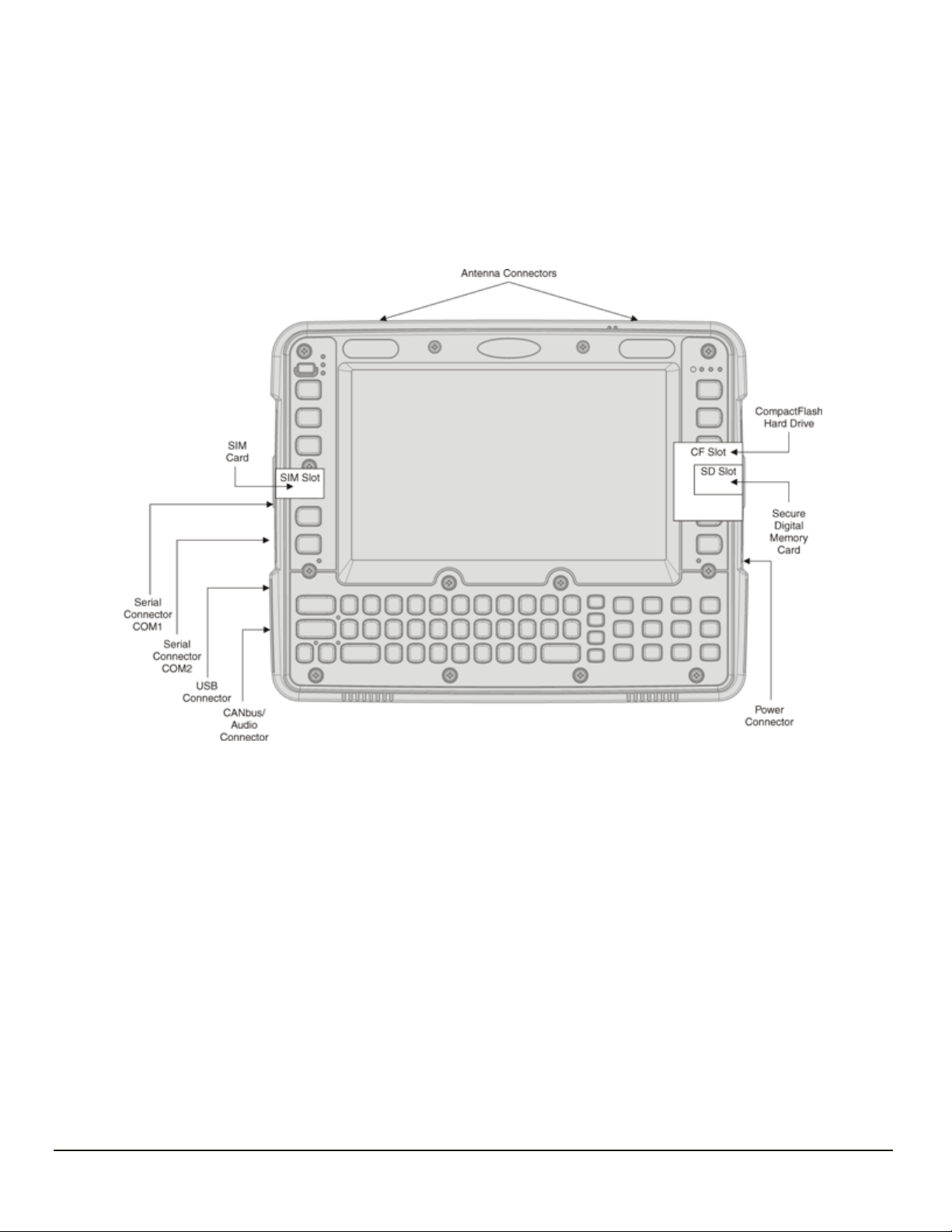
External Connectors
Power the Thor VM1 off before attaching a cable to any port (serial, USB, Audio/CAN, etc.).
Most external connectors for the Thor VM1 are located on the Quick Mount Smart Dock:
l COM1 connects to a serial bar code scanner, screen blanking cable, serial printer or PC.
l COM2 connects to a serial bar code scanner, screen blanking cable, serial printer or PC.
l USB accepts a dongle cable with a USB Host port and a USB Client port.
l CANbus/Audio accepts a cable with connections for a mono headset/microphone or a cable with
CANbus adapters.
The power connector is on the dock.
Antenna connectors are located on the rear of the Thor VM1.
2-11
Page 30

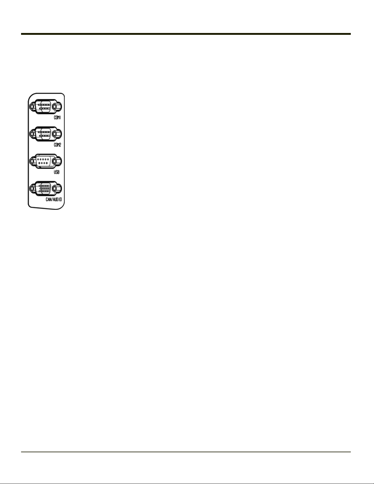
Serial Connector (COM1 and COM2)
The COM1 and COM2 connectors are D-9 male connectors located on the back of the Quick Mount Smart Dock.
Power the Thor VM1 off before attaching a cable to any port (serial, USB, Audio/CAN, etc.).
The serial connectors are industry-standard RS-232, PC/AT standard 9–pin “D” male connector.
By default, Pin 9 is configured to provide +5V for an external bar code scanner. Pin 9 of COM1 or COM2 may also be
configured to provide RI.
If a COM port is not being used for a scanner, it can be used for screen blanking when the vehicle is in motion.
Pinout
Pin Signal Description
1 DCD Data Carrier Detect – Input
2 RXD Receive Data – Input
3 TXD Transmit Data – Output
4 DTR Data Terminal Ready – Output
5 GND Signal/Power Ground
6 DSR Data Set Ready – Input
7 RTS Request to Send – Output
8 CTS Clear to Send – Input
+5VDC
9
Shell CGND Chassis Ground
or
RI
Bar Code Scanner Power - 500mA max
or
Ring Indicator - Input
2-12
Page 31

Screen Blanking
The screen blanking signal can be provided either by a Honeywell Screen Blanking Box or a user supplied switch or relay.
l A screen blanking box can be used on a vehicle that provides voltage on vehicle motion. Voltage must be within the
range specified on the screen blanking box label.
l A switch or relay can be used when an electrical signal is not available or is outside the acceptable range of the screen
blanking box.
A serial cable must be used to connect the screen blanking device:
l An optional Screen Blanking Box Cable is available from Honeywell, or
l A user supplied serial cable can be used. The cable must provide wires from pins 7 and 8 of the connector. No other
wires are used.
Do not enable Screen Blanking until the cable is properly connected to the specified COM port.
Serial Cable
Optional Honeywell Screen Blanking Box Cable (part number VM1080CABLE) or customer built cable with the following
specifications.
DB9 Female
with Screen Blanking Box
Function
1 Not Used Not Used
2 Not Used Not Used
3 Not Used Not Used
4 Not Used Not Used
5 Not Used Not Used
Function
with Switch
Wire color from
Honeywell Cable
2-13
Page 32

DB9 Female
6 Not Used Not Used
7 (RTS) Connected to Screen Blanking Box Connected to Switch Black (see note)
8 (CTS) Connected to Screen Blanking Box Connected to Switch Gray (see note)
9 Not Used Not Used
Note: Wire colors only apply to optional Honeywell Screen Blanking Box Cable, VM1080CABLE. Wire colors may vary in a
user-supplied cable.
Proper COM port settings to support screen blanking are located in Start > Settings > Control Panel > Screen Control.
with Screen Blanking Box
Function
Function
with Switch
Wire color from
Honeywell Cable
Screen Blanking Box
Caution
Please refer to the label on the screen blanking box for allowable input voltage range.
The Screen Blanking Box is designed to monitor a connection to a vehicle motion sensing circuit. When motion is detected, the
Screen Blanking Box opens the connection between the output feeds (which are connected to Pins 7 and 8 of the Thor VM1)
and the display on the Thor VM1 is blanked. When motion is no longer detected the Screen Blanking Box provides a connection
between the output feeds. After the configured Screen On delay, if any, the Thor VM1 screen is displayed.
Please refer to the wiring instructions, including appropriate cautions and warnings, in the Thor VM1 Vehicle Mounting
Reference Guide.
Screen Blanking with Switch
In applications where it is impractical to use the screen blanking box due to vehicle voltage or lack of a motion sensing signal,
screen blanking can be controlled via a user supplied switch or relay that provides an electrical conductive connection between
the wires connected to Pins 7 and 8 of the screen blanking cable on vehicle motion.
Please refer to the wiring instructions, including appropriate cautions and warnings, in the Thor VM1 Vehicle Mounting
Reference Guide.
2-14
Page 33

USB Connector
The USB connector is a D-9 female connector located on the back of the Quick Mount Smart Dock.
Power the Thor VM1 off before attaching a cable to any port (serial, USB, Audio/CAN, etc.).
Pin Signal Description
1 GND Common ground
2 USBC_D+ USB client data signal
3 USBC_D- USB client data signal
4 USB_H1_PWR USB host 1; 5V output power
5 GND Common ground
6 GND Common ground
7 USB_H1_D+ USB host 1 data signal
8 USB_H1_D- USB host 1 data signal
9 USBC_VBUS USB client 5V detect from attached host
2-15
Page 34
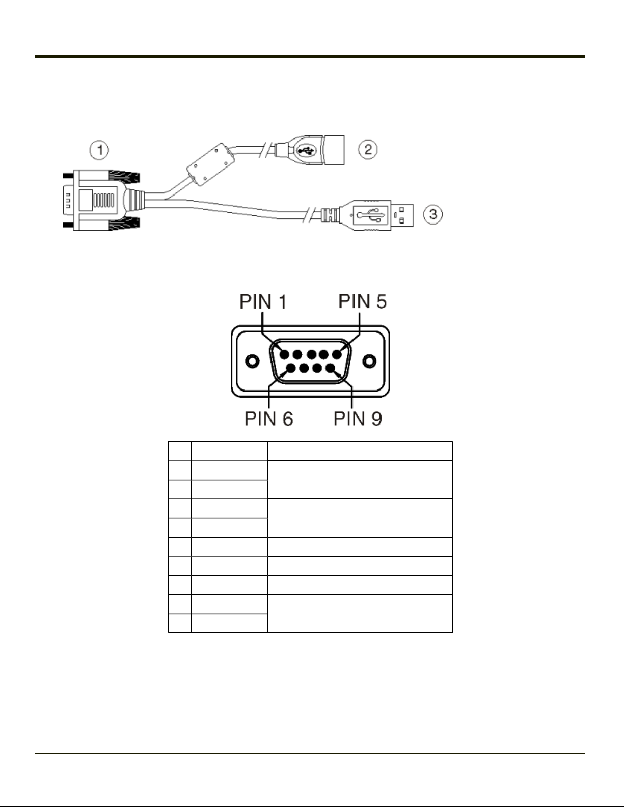
USB Dongle Cable
USB dongle cables have a Host port and a Client port.
D9 Male Connector
1. D9 Connector
2. USB Host
Connector(s)
3. USB Client
Connector
Pin Signal Description
1 GND Common ground
2 USBC_D+ USB client data signal
3 USBC_D- USB client data signal
4 USB_H1_PWR USB host 5V output power
5 GND Common ground
6 GND Common ground
7 USB_H1_D+ USB host 1 data signal
8 USB_H1_D- USB host 1 data signal
9 USBC_VBUS USB client 5V detect from attached host
2-16
Page 35

USB Host Connector
USB Client Connector
Pin Signal Description
1 5V_USB USB Power, Current Limited
2 USB_H1_D- USB D-
3 USB_H1_D+ USB D+
4 GND USB Power Return
Shell CGND Chassis Ground
Pin Signal Description
1 5V_USB USB Power, Current Limited
2 USB_H1_D- USB D-
3 USB_H1_D+ USB D+
4 GND USB Power Return
Shell CGND Chassis Ground
2-17
Page 36

Power Supply Connector
1. Power
Connector
2. Power
Switch
Power is supplied to the Thor VM1 through the power connector. Additionally this assembly provides a connection point for the
vehicle’s chassis ground to be connected internally to the conductive chassis of the computer.
The Thor VM1 internal power supply can accept DC input voltages in the range of 10 to 60 Volts DC.
Pin Signal Description
1 V In+ 10-60V DC input +
2 V In+ 10-60V DC input +
3 V In- input -
4 V In- input -
5 GND Chassis ground
6 Ignition +0V to 60V to start terminal
2-18
Page 37

CANbus / Audio Connector
The CANbus/Audio connector is a D-15 male connector located on the back of the Quick Mount Smart Dock.
The connector supports a headset adapter cable or a CANbus cable. The Thor VM1 does not support connecting audio and
CANbus simultaneously.
Pin Signal Name Description
1 - CAN reserved
2 CAN_L CAN_L bus line dominant low
3 CAN_GND CAN Ground
4 - CAN reserved
5 GND Optional ground
6 Audio return Headset return
7 Audio output Headset output
8 Mic input Microphone input
9 Mic return Microphone return
10 Audio Return
11 GND Optional ground
12 CAN_SHLD
13 CAN_H CAN_H bus line dominant high
14 - CAN reserved
15 CAN_V+ Option CAN external Power Supply
2-19
Page 38

Headset Adapter Cable
The headset cable attaches to the CANbus / Audio connector and provides a quick connect connection for a headset.
D15 Female Connector
Pin Signal Description
1 - Not used
2 - Not used
3 - Not used
4 - Not used
5 - Not used
6 Audio return Headset return
7 Audio output Headset output
8 Mic input Microphone input
9 Mic return Microphone return
10 - Not used
11 - Not used
12 - Not used
13 - Not used
14 - Not used
15 - Not used
2-20
Page 39

Quick Connect Headset Connector
Pin Signal Description
1 Mic input Microphone input
2 Mic return Microphone return
3 Audio output Headset output
4 Audio return Headset return
2-21
Page 40

CANbus Cable
The CANbus interface is a virtual COM9 port. This port can be accessed using standard Windows API calls.
D15 Female Connector
Pin Signal Description
1 - Not used
2 CAN_L CAN_L bus line dominant low
3 CAN_GND CAN ground
4 - CAN reserved
5 GND Ground
6 - Not used
7 - Not used
8 - Not used
9 - Not used
10 - Not used
11 GND Optional ground
12 CAN_SHLD
13 CAN_H CAN_H bus line dominant high
14 - CAN reserved
15 CAN_V+ CAN external power supply
2-22
Page 41

9-Pin J1939 (Deutsch) Connectors
Receptacle
J1939 Female
Pin Signal Description
A CAN_GND CAN Ground
B CAN_V+ Option CAN external Power Supply
C CAN_H CAN_H bus line dominant high
D CAN_L CAN_L bus line dominant low
E CAN_SHLD
F - Not used
G - Not used
H - Not used
J - Not used
Socket
J1939 Male
2-23
Page 42

Antenna Connections
The Thor VM1 is equipped with an 802.11 radio and can be ordered with internal antennas or external remote mount antennas.
When the Thor VM1 is ordered with internal antennas, the external antenna connectors are not used. GPS and WWAN are
optional on the Thor VM1 and require external remote mount antennas.
1. WI-FI (MAIN) (Red label) 802.11 Main External Antenna Connector
2. WI-FI (AUX) (Yellow label) 802.11 Auxiliary External Antenna Connector
3. GPS (Green label) GPS Antenna Connector
4. MOBILE NET (Blue label) WWAN Antenna Connector
Antenna Connector
When the Thor VM1 is ordered with the internal antenna option, the 802.11 antenna connectors on the back are not connected
to the 802.11 radio. Instead the internal antenna is connected to the 802.11 radio.
Remove the rubber cap, if present, from the antenna connector before connecting an external antenna.
Internal WiFi Antenna
If the internal WiFi antenna option is ordered, an antenna is mounted inside the Thor VM1. The internal antenna is not user
accessible.
Vehicle Remote Antenna
The external antennas can be remotely mounted on the vehicle. See the Thor VM1 Vehicle Mounting Reference Guide for
instruction. External antenna kits are available for the 802.11 WiFi radio, GPS and WWAN.
2-24
Page 43

Keyboard Options
The 2nd, ALT, CTRL and Shift keys (when present) are sticky keys. The keyboard LED behavior. identifies the active sticky
modifier mode state of the keyboard.
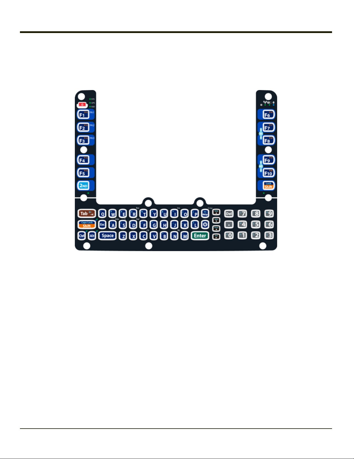
64-Key QWERTY Keyboard
The Thor VM1 has a QWERTY keyboard, available with a standard overlay, an IBM 3270 overlay or an IBM 5250 overlay.
l Because the keyboard only has 64 keys, all functions are not visible (or printed on the keyboard). Therefore the Thor
VM1 keyboard supports what is called hidden keys -- keys that are accessible but not visible on the keyboard.
l A key or combination of keys can be remapped to provide a single keypress, a string of keypresses or to execute an
application or command. Key remapping is configured via the KeyPad option in the Control Panel (Start > Settings >
Control Panel > KeyPad).
l Remapped keys persist across a warmboot or power cycle.
l The keyboard does not have a NumLock indicator or key. NumLock is always On.
l The warmboot behavior of CapsLock can be set via the Misc tab in Start > Settings > Control Panel > Options.
The Thor VM1 keyboard keys are backlit.
l By default, the keyboard backlight follows the display backlight. When the display backlight is on, the keyboard
backlight is on.
l If the display backlight brightness is increased (or decreased) the keyboard backlight brightness is increased (or
decreased).
2-25
Page 44
l The keyboard backlight and the display share the same timer, which is configured in Start > Settings > Control Panel >
Power.
l The keyboard backlight can be disabled. See Start > Settings > Control Panel > Options > Misc tab.
IBM 3270 Overlay
2-26
Page 45

IBM 5250 Overlay
2-27
Page 46

12-Key Keyboard
The 12-key keyboard is available on the Thor VM1 running Windows CE 6.0.
l Because the keyboard only has 12 keys, all functions are not visible (or printed on the keyboard). Therefore the Thor
VM1 keyboard supports what is called hidden keys -- keys that are accessible but not visible on the keyboard.
l A key or combination of keys can be remapped to provide a single keypress, a string of keypresses or to execute an
application or command. Key remapping is configured via the keyboard option in the Control Panel (Start > Settings >
Control Panel > KeyPad).
l Remapped keys persist across a warmboot or power cycle.
l The keyboard does not have a NumLock indicator or key. NumLock is always On.
l The warmboot behavior of CapsLock can be set via the Misc tab in Start > Settings > Control Panel > Options.
The Thor VM1 keyboard keys are backlit.
l By default, the keyboard backlight follows the display backlight. When the display backlight is on, the keyboard
backlight is on.
l If the display backlight brightness is increased (or decreased) the keyboard backlight brightness is increased (or
decreased).
l The keyboard backlight and the display share the same timer, which is configured in Start > Settings > Control Panel >
Power.
l The keyboard backlight can be disabled. See Start > Settings > Control Panel > Options > Misc tab.
The integrated keypad contains five programmable keys, a blue modifier key and an orange modifier key.
2-28
Page 47

Keyboard LEDs
Shift LEDs
Note: The 64-keyThor VM1 has two Shift keys with an LED beside each key. The 12-key Thor VM1 has a single Shift key
and LED.
The Shift LEDs indicate the state of the keyboard Shift mode. If Shift is enabled the Shift LEDs beside both Shift keys (64-key
only) blink green. When CapsLock is enabled, both Shift LEDs (64-key only) are lit solid green. When Shift and CapsLock are
both off, the LEDs are off.
Press either Shift key to toggle Shift On and Off. press 2nd plus either Shift key to toggle CapsLock On or Off.
Secondary Keys LED
The Thor VM1 keyboard is equipped with several secondary keys. These keys are identified by the superscript text found on
the keyboard keys.
The secondary keys are accessible by using two (2) keystrokes: the 2nd key followed by the superscript key.
Once the 2nd state is enabled (by pressing the 2nd key) the Secondary Mode LED is illuminated and the 2nd state is enabled
until another key is pressed.
The 2nd key is toggled on with a 2nd key press and then immediately off with another 2nd key press.
For example:
Press 2nd and F1 to generate F11.
Ctrl and Alt Key LEDs
Note: Ctrl and Alt keys and the associated LEDs are not present on the 12-key version.
When the modifier keys (Ctrl or Alt) are active, the LED located next to the key is illuminated. The modifier key remains active
until:
l The modifier key is pressed again, or
l A non-modifier key is pressed.
USB Keyboard / Mouse
A standard USB keyboard or mouse can be attached to the Thor VM1 using the appropriate dongle cable.
The dongle cable attaches to the Thor VM1 and provides a USB connector. Please refer to documentation provided with the
USB keyboard or mouse for more information on their operation.
2-29
Page 48

LED Functions
1. System LEDs
2. Connection LEDs
3. 2nd LED
4. Shift/CapsLock LED
5. Shift/CapsLock LED *
6. Ctrl LED *
7. Alt LED *
* 64-key keyboards only
2-30
Page 49

System LEDs
SYS (System Status) LED
LED Behavior System State
Solid Green
1. SYS (System Status) LED
2. UPS (Uninterruptible Power Supply) LED
3. SSD (Solid State Drive) LED
l On
l On but Backlight Off
l On but Display Off
Green blinking very slowly
External power present
(1/2 sec. on, 4 1/2 sec. off)
Off
External power not present
Green blinking slowly
External power present
(1/2 sec. on, 1 1/2 sec. off)
Green blinking slowly
External power not present
(1/2 sec. on, 1 1/2 sec. off)
l Suspend
l Off
l Suspend
CPU temperature less than -20ºC,
Heater warming CPU for 30 seconds
CPU temperature less than -20ºC,
Need to move unit to warmer environment
2-31
Page 50

UPS Status LED
The behavior of the UPS LED depends if external power is connected or not.
External Power Present
LED Behavior Status
Off
l No UPS charging,
l UPS charged
Solid Green UPS charging
l Any charging fault,
l Out of charging temperature range,
Solid Amber
l No UPS present,
l Charge timeout
External Power Not Present
LED Behavior Status
Off
l Unit off,
l UPS not present
Solid Amber UPS supplying power and discharging
Solid Red Approximately 2 minutes runtime until shutdown
SSD (Solid State Drive) LED
LED Behavior Status
Flashing Green SSD read or write activity.
Off No SSD read or write activity.
2-32
Page 51

Connection LEDs
WWAN LED
LED Behavior Status
Solid Green Indicates a WWAN connection to a network.
Off Indicates no WWAN connection.
1. WWAN LED
2. WiFi LED
3. Bluetooth LED
WiFi LED
LED Behavior Status
Solid Green Indicates a connection with an IP address to an Access Point
Off Indicates no connection to an Access Point.
Bluetooth LED
LED Behavior Status
Blue Blinking Slowly Bluetooth is paired but not connected to a device.
Blue Blinking Medium Bluetooth is paired and connected to a device.
Blue Blinking Fast Bluetooth is discovering Bluetooth devices.
Off Bluetooth hardware has been turned off.
The Bluetooth LED blinks once every 6 seconds when the Bluetooth client is paired but not connected. It blinks once for a very
short time every 2 seconds when paired and connected. It blinks every second when in discovery. The LED is off when the
Bluetooth client is off.
2-33
Page 52

Keyboard LEDs
The keyboard LEDs are located near the specified key.
2nd LED
LED Behavior Status
l Indicates the 2nd modifier key is active. 2nd mode is invoked for the next keypress
Solid Green
Off 2nd mode is not invoked.
Shift LEDs
For the 64 key keyboard, there is one LED next to each Shift key. Both LEDs indicate the status of Shift mode and Caps Lock
mode.
For the 12-key keyboard, there is a single Shift key and a single LED.
LED Behavior Status
Blinking Green
only.
l Pressing the 2nd key a second time exits this modifier mode and turns off the LED.
l Indicates the keypad is in Shift mode. Shift mode is invoked for one keypress.
l Pressing the Shift key places the system in Shift mode.
l To exit Shift mode, press the Shift key again.
l When solid Green, indicates the keypad is in Caps Lock mode. Caps Lock mode is
invoked until canceled.
Solid Green
l Pressing the 2nd key followed by the Shift key places the system in Caps Lock
mode.
l To exit Caps Lock mode, press 2nd + Shift again.
Off Neither Shift or Caps Lock mode is invoked.
Ctrl LED
The Ctrl key is not present on the 12-key keypad.
LED Behavior Status
l Indicates the Ctrl modifier key is active. Ctrl mode is invoked for the next keypress
Solid Green
Off Ctrl mode is not invoked.
only.
l Pressing the Ctrl key a second time exits this modifier mode and turns off the LED.
2-34
Page 53

Alt LED
The Alt key is not present on the 12-key keypad.
LED Behavior Status
l Indicates the Alt modifier key is active. Alt mode is invoked for the next keypress
Solid Green
Off Alt mode is not invoked.
only.
l Pressing the Alt key a second time exits this modifier mode and turns off the LED.
2-35
Page 54

Display
The display is a thin-film transistor display capable of supporting WVGA graphics modes. Display size is 800 x 480 pixels. The
display covering is designed to resist stains. The touch screen allows signature capture and touch input. The display supports
screen blanking to eliminate driver distraction when the vehicle is in motion.
Touch Screen
The touch screen is a Resistive Panel with a scratch resistant finish that can detect touches by a stylus, and translate them
into computer commands. In effect, it simulates a computer mouse. Only Delrin or plastic styluses should be used. A right
mouse click is simulated by touching and holding the screen for the appropriate time interval.
Always use the point of the stylus for tapping or making strokes on the display. Never use an actual pen, pencil, sharp or
abrasive object to write on the touch screen.
An extra or replacement stylus may be ordered.
A replaceable touch screen protective film is available when the Thor VM1 is used in an abrasive environment. Contact
Technical Assistance for availability.
Note: If the touch screen is disabled or looses calibration on a Thor VM1 with the 12 key keypad, you must use a USB
mouse or keyboard attached to the Thor VM1 to access the control panel to re-enable or recalibrate the touch screen.
Touch Screen Defroster
Extended temperature versions of the Thor VM1 contain a touch screen defroster. The touch screen defroster can be disabled
when not needed (Start > Settings > Control Panel > Peripherals). The defroster trip point is configurable. The defroster is
always disabled when the device is operating from UPS battery power.
Screen Blanking
Screen blanking (blackout) can be enabled when the vehicle is in motion. A serial cable must be attached to the Thor VM1 and
the Thor VM1 must be configured to enable screen blanking (Start > Settings > Control Panel >Screen Control). Once screen
blanking is enabled, the display is blanked out any time when the cable sends the signal the vehicle is in motion. If the cable is
removed, screen blanking is disabled and the display remains on.
Display Backlight Control
The display brightness on a Thor VM1 equipped with an outdoor display can be configured to automatically adjust depending on
the ambient light level (Start > Settings > Control Panel > Screen Control).
Note: When automatic brightness control is enabled, the manual display brightness controls described below have no
effect.
The display brightness can be adjusted manually, via the keypad:
l Use the 2nd + F7 keypress to increase backlight brightness and the 2nd + F8 keypress to decrease backlight
brightness.
2-36
Page 55

Disconnect UPS Battery
Equipment Required- User Supplied:
l Torquing tool capable of measuring inch pounds
l #2 Philips screwdriver bit
Caution
The UPS battery must be disconnected before shipping the Thor VM1, replacing the UPS battery or replacing the
front panel.
1. For convenience, the Thor VM1 can be removed from the Quick Mount Vehicle Dock, though it is not necessary.
2. If the Thor VM1 remains in the Dock, disconnect the power cable from the Dock.
3. Place the Thor VM1 in Suspend.
4. Place the Thor VM1 face down on a stable surface.
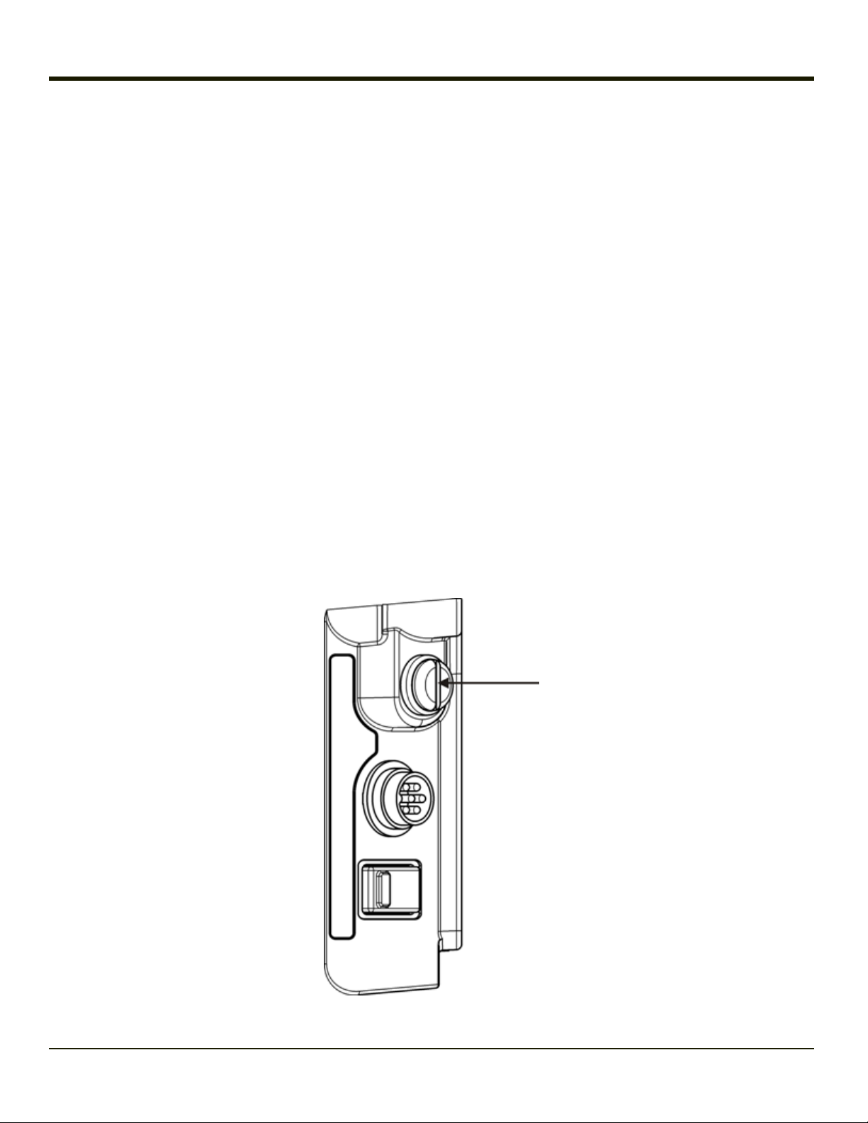
5. Using a #2 Philips bit loosen the M3 screws and then remove the tethered access panel with the SIM label. This panel is
on the right hand side when the Thor VM1 is face down with the top away from the user.
6. Locate the small push button located just below the SIM card installation slot.
2-37
Page 56

7. Press the push button to disconnect the UPS. The UPS battery maintains its charge but is disconnected from the power
circuitry of the Thor VM1.
8. Reattach the access panel, torquing the M3 screws to 4-5 inch pounds using a #2 Philips bit.
9. When the Thor VM1 is attached to external power, the UPS battery is automatically reconnected.
2-38
Page 57

Install SD Card
Equipment Required - User Supplied:
l Torquing tool capable of measuring inch pounds
l #2 Philips screwdriver bit
l SD card - The following commercially available SD cards are recommended:
o
Transcend®2GB Industrial SD card (80X Speed) - TS2GSD80I
o
ATP 4GB Industrial Grade SDHC card - AF4GSDI
1. For convenience, the Thor VM1 can be removed from the Quick Mount Vehicle Dock, though it is not necessary.
2. Place the Thor VM1 in Suspend by pressing the Power button.
3. Place the Thor VM1 face down on a stable surface.
4. Using a Phillips screwdriver (not supplied) loosen the screws and then remove the tethered access panel with the SSD
and SD label. This panel is on the left hand side when the Thor VM1 is face down with the top away from the user.
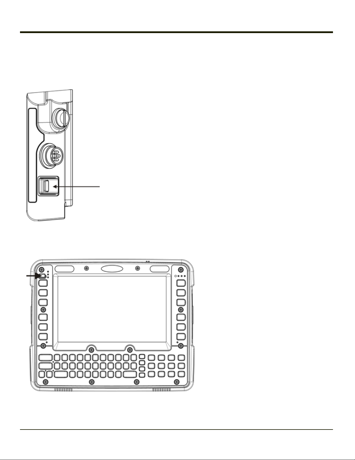
5. Locate the SD card installation slot.
2-39
Page 58

6. Slide the SD card into the slot. The label side (front) of the SD card faces toward the back of the Thor VM1.
7. Reattach the access panel, torquing the screws to 4-5 inch pounds.
8. If removed, reinstall the Thor VM1 in the Dock.
9. Resume the Thor VM1 from suspend.
10. When using Windows explorer to view My Device, the SD card is identified as SD Card. Some versions may label it
Storage Card instead.
2-40
Page 59

Install SIM Card
Equipment Required - User Supplied:
l Torquing tool capable of measuring inch pounds
l #2 Philips screwdriver bit
1. For convenience, the Thor VM1 can be removed from the Quick Mount Vehicle Dock, though it is not necessary.
2. Place the Thor VM1 in Suspend by pressing the Power button.
3. Place the Thor VM1 face down on a stable surface.
4. Using a Phillips screwdriver (not supplied) loosen the screws and then remove the tethered access panel with the SIM
label. This panel is on the right hand side when the Thor VM1 is face down with the top away from the user.
5. Locate the SIM card installation slot.
2-41
Page 60

6. Slide the SIM card into the slot.
7. Reattach the access panel, torquing the screws to 4-5 inch pounds.
8. If removed, reinstall the Thor VM1 in the Dock.
9. Resume the Thor VM1 from suspend.
2-42
Page 61

Field Replaceable Front Panel
Equipment Required - User Supplied:
l Torquing tool capable of measuring inch pounds
l #2 Philips screwdriver bit
Caution
Before replacing the Thor VM1 front panel, the internal UPS battery must be disconnected.
The front panel of the Thor VM1 is field replaceable. The front panel assembly contains the keyboard, touch screen and
optional defroster. Should any of these components fail, the front panel assembly can easily be replaced to reduce downtime.
The replacement front panel is available in several configurations:
l 64-key ANSI keyboard with standard touch screen or cold storage touch screen
l 64-key 3270 keyboard with standard touch screen or cold storage touch screen
l 64-key 5250 keyboard with standard touch screen or cold storage touch screen
l 12-key keyboard with standard touch screen or cold storage touch screen
Replace Front Panel
1. Place the Thor VM1 on a clean, well-lit surface before performing the front panel replacement.
2. Place the Thor VM1 in Suspend by pressing the Power button.
3. Remove the Thor VM1 from the Quick Mount Smart Dock.
4. Disconnect the UPS.
5. Loosen the fourteen (14) captive M3 screws holding the front panel. Use a #2 Philips bit.
2-43
Page 62

5. Carefully lift the front panel away from the device.
A. Slot on Thor VM1 body
B. Wiring connector on Thor VM1
body
C. Wiring connector on front panel
D. Tab on front panel
6. Position the replacement front panel so the tab on the back of the front (D in figure above) panel lines up with the slot (A
in figure above) on the Thor VM1. Be sure the two wiring connectors (B and C in figures above) are also aligned.
7. Gently press the front panel into place.
8. Tighten the fourteen (14) captive M3 screws. In the order shown in the top figure above, use a #2 Philips bit and torque
the screws to 6-7 inch pounds.
9. Reinstall the Thor VM1 in the Quick Mount Smart Dock.
10. When the Thor VM1 is placed in the powered dock, the UPS battery automatically reconnects.
11. Restart the Thor VM1.
12. When restarted, the Thor VM1 automatically recognizes the keyboard type (12 or 64 keys).
13. If the defroster configuration has changed, use the Test button on the Peripherals control panel to update the Thor VM1
defroster configuration.
2-44
Page 63

Field Replaceable UPS Battery
Requirements - User Supplied:
l Torquing tool capable of measuring inch pounds
l #2 Philips screwdriver bit
Caution
Before replacing the Thor VM1 UPS battery, the internal UPS battery must be disconnected.
The UPS battery in the Thor VM1 is field replaceable. Should the UPS battery fail, it can easily be replaced to minimize
downtime.
Replace UPS Battery
1. Place the Thor VM1 on a clean, well-lit surface before performing the UPS battery replacement.
2. Place the Thor VM1 in Suspend by pressing the Power button.
3. Remove the Thor VM1 from the Quick Mount Smart Dock.
4. Disconnect the UPS.
5. Loosen the fourteen (14) captive M3 screws holding the front panel. Use a #2 Philips bit.
2-45
Page 64

5. Carefully lift the front panel away from the device.
A. Wiring Connector
B. UPS Battery
C. Foam Pads
D. Release Tab on
Wiring Connector
6. Note the orientation of the UPS battery. Lift the UPS battery out of the battery well and place it outside the well. Do not
pull on the wires attaching the battery to the Thor VM1 while lifting the battery.
7. Locate the retaining tab on the wiring connector for the UPS battery. Press on the tab and gently disconnect the UPS
battery wiring from the Thor VM1.
8. Remove the old battery and set it aside.
9. Inspect the battery well to verify the two foam pads are still in place.
10. Align the wiring connector on the new UPS battery with the connector on the Thor VM1. Gently press the connector into
place until the retaining tab snaps into place.
11. Place the UPS battery into the well. Note the orientation of the battery in the illustration below. The flat surface of the
battery points toward the bottom of the Thor VM1. Make sure all wires are inside the battery well so they are not pinched
when the front panel is reinstalled..
2-46
Page 65

A. Slot on Thor VM1 body
B. Wiring connector on Thor VM1
body
C. Wiring connector on front panel
D. Tab on front panel
12. Position the front panel so the tab on the back of the front (D in figure above) panel lines up with the slot (A in figure
above) on the Thor VM1. Be sure the two wiring connectors (B and C in figures above) are also aligned.
13. Gently press the front panel into place.
14. Tighten the fourteen (14) captive M3 screws. In the order shown in the top figure above, use a #2 Philips bit and torque
the screws to 6-7 inch pounds.
15. Reinstall the Thor VM1 in the Quick Mount Smart Dock.
16. When the Thor VM1 is placed in the powered dock, the UPS battery automatically reconnects. The UPS battery
automatically begins charging from the powered dock.
17. Restart the Thor VM1.
2-47
Page 66

2-48
Page 67

Chapter 3: Software
Introduction
There are several different aspects to the setup, configuration and operation of the Thor VM1. Many of the setup and
configuration settings are dependent upon the optional features such as hardware and software installed on the unit. The
examples found in this section are to be used as examples only, the configuration of your specific Thor VM1 computer may
vary. The following sections provide a general reference for the configuration of the Thor VM1 and some of its optional features.
Operating System
Your Thor VM1 operating system is Microsoft® Windows® Embedded CE 6. The Thor VM1 operating system revision is
displayed on the Desktop. This is the default setting for the Desktop Display Background.
Windows CE Operating System
Note: For general use instruction, please refer to commercially available Windows CE user’s guides or the Windows CE on-
line Help application installed with the Thor VM1 operating system.
This segment assumes the system administrator is familiar with Microsoft Windows options and capabilities loaded on most
standard Windows computers.
Therefore, the sections that follow describe only those Windows capabilities that are unique to the Thor VM1 and its Windows
CE environment.
3-1
Page 68

General Windows CE Keyboard Shortcuts
Use the keyboard shortcuts in the chart below to navigate with the Thor VM1 keyboard. These are standard keyboard shortcuts
for Windows CE applications.
Press these keys … To …
CTRL + C Copy
CTRL + X Cut
CTRL + V Paste
CTRL + Z Undo
DELETE Delete
SHIFT with any of the arrow keys
Select more than one item in a window or on the desktop, or select text
within a document.
CTRL+A Select all.
ALT+ESC Cycle through items in the order they were opened.
CTRL+ESC Display the Start menu.
ALT+Underlined letter in a menu name Display the corresponding menu.
Underlined letter in a command name on an
open menu
Carry out the corresponding command.
ESC Cancel the current task.
The touch screen provides equivalent functionality to a mouse:
l A touch on the touch screen is equivalent to a left mouse click.
l Many items can be moved by the “drag and drop” method, touching the desired item, moving the stylus across the
screen and releasing the stylus in the desired location.
l A double stylus tap is equivalent to a double-click.
l A touch and hold is equivalent to a right mouse click
l Devices with Shift and Ctrl Keys The Shift and Ctrl keys can be used with the touch screen for multiple selection of
1
.
items.
l To select disconnected items, press the Ctrl key and then touch each item to be selected in the set. Press the
Ctrl key again to terminate this mode.
l To select a connected set of items, press the Shift key, then touch the first item in the series. Touch the last item
in the series. Press the Shift key again to terminate the selection mode.
1
Some applications may not support this right-click method. Please review documentation for the application to see if it pro-
vides for right mouse click configuration.
3-2
Page 69

Rebooting the Thor VM1
If a USB drive, such as a thumb drive is attached to the Thor VM1, the device attempts to boot from the USB
drive:
l If the USB drive contains a bootable sector, the Thor VM1 boots from the USB drive.
l If the USB drive does not contain a bootable sector, the Thor VM1 does not boot. Remove the USB drive
and boot the Thor VM1 again.
Warmboot
A warmboot reboots the Thor VM1 without erasing any registry data. Configuration settings and data in RAM are preserved
during a warmboot. Network sessions are lost and any data in running applications that has not been previously saved may be
lost. CAB files already installed remain installed.
There are several warmboot methods available:
l Using the Registry, select Start > Settings > Control Panel > Registry and tap the Warmboot button. The Thor VM1
immediately warmboots.
l Using the Start menu, select Start > Run and type WARMBOOT in the text box. Press Enter. The Thor VM1
immediately warmboots. The WARMBOOT text command is not case-sensitive.
l For the 64-key kepad, use the Ctrl + Alt + Del keypress sequence to reboot the Thor VM1. The keys may be pressed in
sequence; they do not need to be held down simultaneously.
l For the 12-key kepad, use the 2nd + F5 + Shift keypress sequence to reboot the Thor VM1. The keys may be pressed
in sequence; they do not need to be held down simultaneously. This reboot sequence also works on the 64-key keypad.
Restart
A restart reboots the Thor VM1 without erasing any registry data. Configuration settings are preserved during a restart.
Network sessions are lost and any data in running applications that has not been previously saved may be lost. The contents
of RAM are erased and the operating system and CAB files are reloaded.
To initiate a restart:
l Using the Registry, select Start > Settings > Control Panel > Registry and tap the Restart button. The Thor VM1
immediately restarts.
l Using the Start menu, select Start > Run and type RESTART in the text box. Press Enter. The Thor VM1 immediately
restarts. The RESTART text command is not case-sensitive.
Clearing Persistent Storage / Reset to Default Settings
Use theRegistry control panel Load Factory Defaults button to set the Thor VM1 registry back to factory defaults. No other
clearing is available or necessary.
Folders Copied at Startup
If any of the following folders are created in the System folder, they are copied at startup:
System\Desktop copied to Windows\Desktop
System\Favorites copied to Windows\Favorites
System\Fonts copied to Windows\Fonts
3-3
Page 70

System\Help copied to Windows\Help
System\Programs copied to Windows\Programs
AppMgr copied to Windows\AppMgr
Recent copied to Windows\Recent
This function copies only the folder contents, no sub-folders.
The Windows\Startup folder is not copied on startup because copying this folder has no effect on the system or an incorrect
effect.
Files in the Startup folder are executed, but only from System\Startup. Windows\Startup is parsed too early in the boot process
so it has no effect.
Executables in System\Startup must be the actual executable, not a shortcut, because shortcuts are not parsed by Launch.
Saving Changes to the Registry
The Thor VM1 saves the registry when you:
l Warmboot - either from the Registry control panel, the warmboot command or the reboot keypress sequence.
l Restart - from the Registry control panel
l Suspend/Resume - Either user initiated or upon Suspend timer expiration.
l Shutdown - The registry is saved during a controlled shutdown, such as when the UPScharge reaches a critically low
level and external power is not available.
The registry save process takes 0 – 3 seconds. If nothing has been changed, nothing is saved (e.g., 0 seconds).
3-4
Page 71

Software Load
The software loaded on the Thor VM1 consists of Microsoft® Windows® Embedded CE 6 OS, hardware-specific OEM
Adaptation Layer, device drivers, Internet Explorer 6.0 for Windows CE browser and utilities. The software supported is
summarized below:
l Full Operating System License: Includes all operating system components, including Microsoft® Windows®
Embedded CE 6 kernel, file system, communications, connectivity (for remote APIs), device drivers, events and
messaging, graphics, keyboard and touch screen input, window management, and common controls.
l Network and Device Drivers
l Bluetooth
Note: Please contact Honeywell Technical Assistance for software updates and CAB files as they are released by
Honeywell.
Software Applications
The following applications are included:
l WordPad
l Data Collection Wedge (bar code result manipulation)
l ActiveSync
l Transcriber
l Internet Explorer
l Word Viewer
l Excel Viewer
l PDF Viewer
l PowerPoint Viewer
Note that the viewer applications allow viewing documents, but not editing them.
ActiveSync
ActiveSync is pre-loaded. Using Microsoft ActiveSync you can copy files from your Thor VM1 to your desktop/laptop , and
vice versa. After an ActiveSync relationship (partnership) has been established with a desktop/laptop, ActiveSync will
automatically startup each time the Thor VM1 is cabled to the desktop/laptop.
Bluetooth
Start > Settings > Control Panel > Bluetooth
Only installed on a Bluetooth equipped Thor VM1. The System Administrator can Discover and Pair targeted Bluetooth devices
for each Thor VM1. The System Administrator can enable / disable Bluetooth settings and assign a Computer Friendly name
for each Thor VM1.
The Bluetooth control panel can also be accessed by double-tapping the Bluetooth icon in the taskbar or on the desktop.
3-5
Page 72

LXE RFTerm (Optional)
Start > Programs > LXE RFTerm
RFTerm is pre-loaded when ordered. The application can also be accessed by double-clicking the RFTerm desktop icon.
Avalanche
The Wavelink Avalanche Enabler installation file is loaded on the Thor VM1; however, the device is not configured to launch
the installation file automatically. The installation application must be run manually the first time Avalanche is used. Following
installation, the Wavelink Avalanche Enabler will be an auto-launch application. This behavior can be modified by accessing
the Avalanche Update Settings panel through the Enabler Interface.
Software Development
See Also: CE API Programming Guide
The CE API Programming Guide documents Honeywell-specific API calls for the Thor VM1. It is intended as an addition to
Microsoft Windows CE API documentation.
A Software Developers Kit (SDK) and additional information about software development can be found on the Developer
Portal. Please Contact Technical Assistance for more information.
Thor VM1 Utilities
The following files are pre-loaded.
LAUNCH.EXE
Launch works in coordination with registry settings to allow drivers or applications to be loaded automatically into DRAM at
system startup. Registry settings control what gets launched; see the App Note for information on these settings. For
examples, you can look at the registry key
HKEY_LOCAL_MACHINE \ Software \ LXE \ Persist
Launch will execute .CAB files, .BAT files, or .EXE files.
App Note
All applications to be installed into persistent memory must be in the form of Windows CE CAB files. These CAB
files exist as separate files from the main installation image, and are copied to the CE device using ActiveSync,
or using a Compact Flash ATA card. The CAB files are copied from ATA or using ActiveSync Explore into the
folder System, which is the persistent storage virtual drive. Then, information is added to the registry, if desired,
to make the CAB file auto-launch at startup.
The registry information needed is under the key HKEY_LOCAL_MACHINE \ Software \ LXE \ Persist, as follows. The main
subkey is any text, and is a description of the file. Then four mandatory values are added:
FileName is the name of the CAB file, with the path (usually \System).
Installed is a DWORD value of 0, which changes to 1 once auto-launch installs the file.
3-6
Page 73

FileCheck is the name of a file to look for to determine if the CAB file is installed. This will be the name of one of
the files (with path) installed by the CAB file. Since the CAB file installs into DRAM, when memory is lost this file
is lost, and the CAB file must be reinstalled.
Order is used to force a sequence of events. Order=0 is first, and Order=99 is last. Order must be greater than
4 for the Thor VM1. Two items which have the same order will be installed in the same pass, but not in a
predictable sequence.
There are two optional fields that may be added:
1. Delay is used to add a delay after the item is loaded, before the next is loaded. The delay is given in seconds, and
defaults to 0 if not specified. If the install fails (or the file to be installed is not found), the delay does not occur.
2. PCMCIA is used to indicate that the file (usually a CAB file) being loaded is a radio driver, and the PCMCIA slots should
be started after this file is loaded. By default, the PCMCIA slots are off on powerup, to prevent the “Unidentified
PCMCIA Slot” dialog from appearing. Once the drivers are loaded, the slot can be turned on. The value in the PCMCIA
field is a DWORD, representing the number of seconds to wait after installing the CAB file, but before activating the slot
(a latency to allow the thread loading the driver to finish installation). The default value of 0 means the slot is not
powered on. The default values for the default radio drivers (listed below) is 1, meaning one second elapses between the
CAB file loading and the slot powering up.
The auto-launch process proceeds as follows:
l The launch utility opens the registry database and reads the list of CAB files to auto-launch.
l First it looks for FileName to see if the CAB file is present. If not, the registry entry is ignored. If it is present, and the
Installed flag is not set, auto-launch makes a copy of the CAB file (since it gets deleted by installation), and runs the
Microsoft utility WCELOAD to install it.
l If the Installed flag is set, auto-launch looks for the FileCheck file. If it is present, the CAB file is installed, and that
registry entry is complete. If the FileCheck file is not present, memory has been lost, and the utility calls WCELOAD to
reinstall the CAB file.
l Then, the whole process repeats for the next entry in the registry, until all registry entries are analyzed.
l To force execution every time (for example, for AUTOEXEC.BAT), use a FileCheck of “dummy”, which will never be
found, forcing the item to execute.
l For persist keys specifying .EXE or .BAT files, the executing process is started, and then Launch will continue, leaving
the loading process to run independently. For other persist keys (including .CAB files), Launch will wait for the loading
process to complete before continuing. This is important, for example, to ensure that a .CAB file is installed before the
.EXE files from the .CAB file are run.
l Note that the auto-launch process can also launch batch files (*.BAT), executable files (*.EXE), registry setting files
(*.REG), or sound files (*.WAV). The mechanism is the same as listed above, but the appropriate CE application is
called, depending on file type.
Note: Registry entries may vary depending on software revision level and options ordered with the Thor VM1.
LAUNCH.EXE and Persistent Storage
If any of the following directories are created in the System folder, Launch automatically copies all of the files in these
directories:
l AppMgr
l Desktop
l Favorites
l Fonts
l Help
3-7
Page 74

l Programs
l Recent
Note: Files in the Startup folder are executed, but only from System > Startup. They are not copied to another folder.
REGEDIT.EXE
Registry Editor – Use caution when editing the Registry. Make a backup copy of the registry before changes are made.
REGLOAD.EXE
Double-tapping a registry settings file (e.g., REG) causes RegLoad to open the file and make the indicated settings in the
registry.
REGDUMP.EXE
Registry dump – Saves a copy of the registry as a text file. The file, REG.TXT, is located in the root folder.
The Thor VM1 includes a Load User Defaults option in the Registry control panel. This is the preferred method for saving a
backup of the registry. Save the registry file to the System folder on the Reference Guide (persistent storage) or copy the file to
a PC.
WARMBOOT.EXE
Double-click this file to warm boot the computer (i.e., all RAM is preserved). It automatically saves the registry before
rebooting which means configuration changes are not lost.
WAVPLAY.EXE
Double-tapping a sound file (e.g., WAV) causes WavPlay to open the file and run it in the background.
Thor VM1 Command-line Utilities
Command line utilities can be executed by Start > Run > [program name].
PrtScrn.EXE
Command line utility which performs a screen print and saves the file in .BMP format in the \System folder. Tap Start > Run
and type prtscrn and tap OK, or press Enter. There is a 10 second delay before the screen print is made. The device beeps and
the screen captured file (scrnnnnn.bmp) is placed in the \System folder. The numeric filename is incremented by 1 each time
the PrtScrn function is activated. The command is not case-sensitive.
3-8
Page 75

Desktop
Note: For general use instruction, please refer to commercially available Windows CE user’s guides or the Windows on-line
Help application installed in the mobile device.
The Thor VM1 Desktop appearance is similar to that of a desktop PC running a Windows operating system.
At the bottom of the screen is the Start button. Tapping the Start Button causes the Start Menu to pop up. It contains the
standard Windows menu options: Programs, Favorites, Documents, Settings, Help, and Run.
Desktop Icons
At a minimum, the desktop displays icons for My Device, Internet Explorer and the Recycle Bin. Following are a few of the
other icons that may be on the Thor VM1 Desktop. Please Contact Technical Assistance about the latest updates and
upgrades for your operating system.
Icon Function
Access files and programs.
Storage for files that are to be deleted.
Discover and then pair with nearby discoverable Bluetooth devices.
Storage for downloaded files / applications.
Connect to the Internet/intranet.
Used for accessing the appropriate wireless configuration, SCU (Summit Client Utility).
The eXpress Scan utility allows an administrator to scan bar codes to provide the initial network and Avalanche Mobile Device Server address configuration. This eliminates the need to edit radio parameters manually on the Thor VM1. eXpress Scan uses bar codes created with eXpress Config.
3-9
Page 76

Icon Function
RFTerm is an optional terminal emulation program. When RFTerm is installed, this icon is displayed on the
desktop.
A shortcut to the Remote Desktop Connection utility.
Avalanche shortcut. Wavelink® Avalanche Mobility Center™ (Avalanche MC) is a remote client management
system that is designed to distribute software and configuration updates to monitored devices. The enabler for
Wavelink Avalanche is loaded on the Thor VM1 but not installed. When the enabler is installed the Avalanche
icon is displayed on the desktop.
The demo version of Wavelink Telnet CE is installed on all devices. Please Contact Technical Assistance for
licensing information. When installed, license details are maintained in the Wavelink tab in the License Viewer
control panel.
Start button. Access programs, select from the Favorites listing, documents last worked on, change/view settings for the control panel or taskbar, on-line help or run programs.
Taskbar
The number and type of icons displayed are based on the device type, installed options and configuration of the Thor VM1.
My Device Folders
Folder Description Preserved upon Reboot?
Application Data Data saved by running applications No
My Documents Storage for downloaded files / applications No
Network Mounted network drive No
Program Files Applications No
System Internal CF/SD Card (CAB file storage) Yes
Storage Card or SD Card Additional optional storage space Yes
Temp Location for temporary files No
Windows Operating System in Secure Storage No
3-10
Page 77

Wavelink Avalanche Enabler (Optional)
Note: If the user is NOT using Wavelink Avalanche to manage their mobile device, the Enabler should not be installed on the
mobile device(s).
The following features are supported by the Wavelink Avalanche Enabler when used in conjunction with the Avalanche
Manager.
After configuration, Enabler files are installed upon initial bootup and after a hard reset. Network parameter configuration is
supported for:
l IP address: DHCP or static IP
l RF network SSID
l DNS hosts (primary, secondary, tertiary)
l Subnet mask
l Enabler update
Related Manual: Using Wavelink Avalanche
The Thor VM1 has the Avalanche Enabler installation files loaded, but not installed, on the mobile device when it is shipped.
The installation files are located in the System folder on CE devices. The installation application must be run manually the first
time Avalanche is used.
After the installation application is manually run, a reboot is necessary for the Enabler to begin normal performance. Following
this reboot, the Enabler will by default be an auto-launch application. This behavior can be modified by accessing the
Avalanche Update Settings panel through the Enabler Interface.
The designation of the mobile device to the Avalanche CE Manager is LXE_THOR.
Internet Explorer
Start > Programs > Internet Explorer
This option requires a radio card and an Internet Service Provider. There are a few changes in the Windows CE version of
Internet Explorer as it relates to the general desktop Windows PC Internet Explorer options. Tap the “?” button to access
Internet Explorer Help.
3-11
Page 78

Start Menu Program Options
The following list represents the factory default program installation. Your system may contain different items from those
shown below, based on the software and hardware options purchased.
Communication Stores Network communication options
Connect Run this command after setting up a connection
Start (or Stop) FTP
Server
Command Prompt The command line interface in a separate window
eXpress Scan Option. Requires Wavelink Avalanche option eXpress Config.
Internet Explorer Access web pages on the Internet/Intranet
File Viewers
JETCET PDF Viewer View Adobe PDF Documents
Office 2003 Excel
Viewer
Office 2003 PowerPoint
Viewer
Office 2003 Word
Viewer
Microsoft WordPad Opens an ASCII notepad
Remote Desktop Connection Log on to a Windows Terminal Server
LXE RFTerm Option. Terminal emulation application.
Settings
Summit Set Summit radio / network parameters
Transcriber Enter data using the stylus on the touch screen
Wavelink Avalanche Option. Remote management for networked devices
Windows Explorer File management program
l If installed, RFTerm runs automatically at the conclusion of each reboot.
l If installed and enabled, AppLock runs automatically at the conclusion of each reboot.
l The wireless client connects automatically during each reboot.
l Bluetooth re-connects to nearby paired devices automatically at the conclusion of each reboot.
l If installed and pre-configured, Wavelink Avalanche connects remotely and downloads updates automatically during
each reboot.
Begin / end connection to FTP server
View Excel 2003 and compatible documents
View PowerPoint 2003 and compatible documents
View Word 2003 and compatible documents
Access to all Control Panels, a shortcut to the Network and Dialup Control Panel and
access to Taskbar options.
Communication
Start > Programs > Communication
ActiveSync
ActiveSync is pre-loaded on the Thor VM1.
Using Microsoft ActiveSync you can copy files from your Thor VM1 to your desktop computer, and vice versa.
3-12
Page 79

Once an ActiveSync relationship (partnership) has been established with Connect (on a desktop computer), ActiveSync will
synchronize using USB on the Thor VM1.
Connect and LXEConnect
Upon cabling your Thor VM1 to the desktop/laptop, and ActiveSync on the desktop/laptop opens, if the Connect or
LXEConnect installation does not open on your host PC, Contact Technical Assistance.
Start FTP Server / Stop FTP Server
Start > Programs > Communication > Start (or Stop) FTP Server
These shortcuts call the Services Manager to start and stop the FTP server. The server defaults to Off (for security) unless it is
explicitly turned on from the menu.
Summit
Start > Settings > Control Panel > Summit
Use this option to set up radio client profiles.
The Summit Control Panel can also be accessed by double-tapping the Summit icon in the taskbar or on the desktop.
Certs
The Certs option displays a readme file containing details on how the Summit Configuration Utility (SCU) handles certificates
for WPA authentication.
3-13
Page 80

Command Prompt
Start > Programs > Command Prompt
Type help cmd at the command prompt to view valid Pocket PC (Console) commands.
Exit the command prompt by typing exit at the command prompt or tap File > Close.
eXpress Scan
The eXpress Scan utility allows an administrator to scan bar codes to provide the initial network and Avalanche Mobile Device
Server address configuration.This eliminates the need to edit radio parameters manually on the Thor VM1.
eXpress Scan uses bar codes created with eXpress Config.
Internet Explorer
Start > Programs > Internet Explorer
This option requires a WLAN or WWAN card and an Internet Service Provider. There are a few changes in the Windows CE
version of Internet Explorer as it relates to the general desktop Windows PC Internet Explorer options. Tap the ? button to
access Internet Explorer Help.
Media Player
Start > Programs > Media Player
There are few changes in the Windows CE version of Media Player as it relates to the general desktop Windows PC Microsoft
Media Player options.
After the Media Player application is running, click the ? button to access Media Player Help.
3-14
Page 81

File Viewers
The following applications are included:
l JETCETPDF Viewer
l Office 2003 Excel Viewer
l Office 2003 PowerPoint Viewer
l Office 2003 Word Viewer
Note: The viewer applications allow viewing documents, but not editing them.
Microsoft WordPad
Start > Programs > Microsoft WordPad
Create and edit documents and templates in WordPad, using buttons and menu commands that are similar to those used in the
desktop PC version of Microsoft WordPad.
By default WordPad files are saved as .PWD files. Documents can be saved in other formats e.g., .RTF or .DOC.
Tap the ? button to access WordPad Help.
Remote Desktop Connection
Start > Programs > Remote Desktop
There are few changes in the Windows CE version of Remote Desktop as it relates to the general desktop Windows PC
Microsoft Remote Desktop options.
If installed, Remote Desktop on the Thor VM1 can be accessed by Start > Programs > Remote Desktop.
Select a computer from the drop down list or enter a host name and tap the Connect button.
Tap the Options >> button to access the General, Display, Local Resources, Programs and Experience tabs. Tap the ? button
to access Remote Desktop Connection Help.
Settings
Start > Settings
The Settings menu option may include the following:
Control Panel All control panels
Network and Dialup Con-
nections
Taskbar Set Taskbar parameters
Shortcut to control panel. Connect to a network, create a new connection, and adjust parameters for
client connections.
Transcriber
To make changes to the Transcriber application, tap the keyboard icon in the status bar. Select Transcriber from the pop-up
menu. Then open the Input control panel and tap the Options button. Transcriber Options (Start > Settings > Control Panel >
3-15
Page 82

Input Panel) are available only when Transcriber is selected as the active input method. Tap the “?” button or the Help button to
access Transcriber Help.
Windows Explorer
Start > Programs > Windows Explorer
There are a few changes in the Windows CE version of Windows Explorer as it relates to the general desktop PC Windows
Explorer options. Tap the “?” button to access Windows Explorer Help.
3-16
Page 83

Taskbar
Start > Settings > Taskbar
There are a few changes in the Windows CE version of Taskbar as it relates to the general desktop PC Windows Taskbar
options.
When the taskbar is auto hidden, press the Ctrl key then the Esc key to make the Start button appear.
Clicking the Taskbar option on the Settings menu displays the Taskbar General tab and the Taskbar Advanced tab.
See Also: "Taskbar Icons"
General Tab
Factory Default Settings
Always on Top Enabled
Auto hide Disabled
Show Clock Enabled
Advanced Tab
Expand Control Panel
Tap the checkbox to have the Control Panel folders appear in drop down menu format from the Settings > Control Panel menu
option.
3-17
Page 84

Clear Contents of Document Folder
Tap the Clear button to remove the contents of the Document folder.
Taskbar Icons
As Thor VM1 devices and applications open and change state, icons are placed in the Taskbar. In most cases, tapping the icon
in the Taskbar opens the related application.
Refer to Start > Help for an explanation of standard Windows CE taskbar icons.
Following are a few of the Thor VM1 taskbar icons that may appear in the Taskbar. These icons are in addition to the Windows
CE taskbar icons.
Wireless Zero Config Inactive / Connected / Not Connected.
Clicking on the icon opens the Wireless Zero Config utility.
Bluetooth connected / disconnected. Clicking the icon opens the Bluetooth control panel.
ActiveSync Connection
Cerdisp connected (displayed when LXEConnect is connected)
Summit Client signal indicator no signal / excellent signal. Clicking on the icon opens the Sum-
mit Client Utility.
Gobi Connection Manager (WWAN) signal indicator no signal / excellent signal. Clicking on the
icon opens the Gobi Connection Manager.
UPS battery charge indicator. Percent of battery charge is indicated.
External power connected / connected and UPS battery charging.
Current time. Clicking the time display opens the Date/Time control panel.
Click this icon to return to the Desktop.
AppLock switchpad.
Input method, keyboard / input panel / transcriber
CapsLock active
3-18
Page 85

Thor VM1 OS Upgrade
Introduction
Depending on the size of the operating system, the total time required for a successful upgrade may require several minutes.
The OS upgrade files are unique to your Thor VM1 physical configuration and date of manufacture. OS upgrade files designed
for one device configuration should not be used on a different device configuration.
When upgrading the OS or firmware on a Thor VM1 with a 12-key keyboard, it is best to perform the upgrade using either
Wavelink Avalanche or with an external USB keyboard attached.
There may be firmware and BIOS upgrades available for the Thor VM1. Contact Technical Assistance for upgrade information
and instructions. In some cases, it may be necessary to upgrade firmware before upgrading the operating system.
Caution
The Thor VM1 must be connected to external power before upgrading the BIOS, firmware or operating
systems.
If the Thor VM1 is operating on UPS battery power, the upgrade process does not initiate and the Thor VM1 is
not upgraded.
Preparation
l Please Contact Technical Assistance to get the OS upgrade files.
l Honeywell Technical Assistance may advise you that additional upgrades such as BIOS or firmware are required before
upgrading the OS. Please follow any additional upgrade instructions provided by Technical Assistance.
l Use ActiveSync to back up Thor VM1 user files and store them elsewhere before beginning an upgrade on the Thor
VM1.
l Maintain an uninterrupted AC/DC power source to the Thor VM1 throughout this process.
l The CF card with the OS and systems files must be present for the Thor VM1 to boot. Removal or installation of SD or
CF cards should be performed on a clean, well-lit surface.
l Always perform OS updates when the Thor VM1 has a dependable external power source connected to the Thor VM1.
Procedure
1. Verify a dependable power source is applied to the Thor VM1 and will stay connected during the upgrade procedure.
2. Warmboot the Thor VM1 before beginning the update process.
3. Establish an ActiveSync connection between the Thor VM1 and a desktop/laptop computer.
4. Download the OS files from the desktop/laptop to the Thor VM1's System folder.
5. During the file copy process to the Thor VM1 System folder, when asked “Overwrite ?”, select Yes to All.
6. Review the files that were downloaded to the System folder.
7. Restart the Thor VM1.
8. Disconnect from ActiveSync.
9. When the OS finishes loading, check the OS update version by selecting Start > Settings > Control Panel > About >
Software tab.
The touch screen may require calibration, however most Windows OS versions save the calibration data, eliminating the need
to calibrate.
If the Thor VM1 won't boot up after the upgrade is finished, Contact Technical Assistance for re-imaging options.
3-19
Page 86

BIOS
The Microsoft Windows CE operating system is installed before shipping. The default BIOS parameters are configured at that
time. In most cases, it is unnecessary to modify the BIOS parameters.
Generally, it is only necessary to enter the BIOS setup to change the boot order of the drives.
This section is not intended to detail all features of the BIOS, instead it is intended to cover the most commonly used setup
options.
Caution:
Be very careful when using this utility to modify BIOS Setup parameters. The Thor VM1 may generate unexpected
results when incorrect or conflicting parameter values are entered. Selecting incorrect or invalid options may
require the Thor VM1 to be returned for repairs.
The parameters should only be modified by Information Services personnel or the system administrator.
Accessing the BIOS Setup
When the Embedded BIOS screen (Phoenix Technologies) is displayed press the Del key to enter BIOS setup.
Use the arrow keys to move around the screen.
To access and modify the BIOSon the Thor VM1 with 12-key keyboard, an external keyboard must be attached.
Boot Order
To view or edit the boot order, select the Boot tab.
By default, the first device in the boot order is USB Hard Drive.
The second device is the Windows CE Image.
If a USB drive, such as a thumb drive is attached to the Thor VM1, the device attempts to boot from the USB drive:
l If the USB drive contains a bootable sector, the Thor VM1 boots from the USB drive.
l If the USB drive does not contain a bootable sector, the Thor VM1 does not boot. Remove the USB drive and
boot the Thor VM1 again.
Exiting BIOS Setup
To exit the BIOS setup, select the Exit tab and select one of these options:
l Save Setting and Restart
l Exit Setup without Saving Changes
l Reload Factory-Defaults and Restart
3-20
Page 87

Control Panel
Start > Settings > Control Panel orMy Device > Control Panel link
Tap the ? button for Help when changing Thor VM1 Control Panel options.
Option Function
About Software, hardware, versions and network IP. No user intervention allowed.
Accessibility
Administration AppLock Administration utility.
Battery View voltage and status of the internal UPS battery.
Bluetooth Set the parameters for Bluetooth device connections.
Certificates Manage digital certificates used for secure communication.
Data Collection (Wedge)
Date/Time Set Date, Time, Time Zone, and Daylight Savings.
Dialing
Display
Gobi Connection Manager Set parameters for the Wireless Wide Area Network client, if installed.
Input Panel Select the current key / data input method. Select custom key maps.
Internet Options
Customize the way the keyboard, audio, display or mouse function for users with hearing or viewing difficulties.
Wedge utility for data collected from bar code scans. Set data collection device, data
stripping, and prefix/suffix options. Assign baud rate, parity, stop bits and data bits for
COM1 and COM2 ports. Assign collected data manipulation parameters.
Connection setup for modem attached to COM port or CompactFlash slot. . CompactFlash slot not available for modem use on Thor VM1.
Set background graphic and scheme. Set touch screen and keypad backlight properties and timers.
Set General, Connection, Security, Privacy, Advanced and Popups options for Internet
connectivity.
Keyboard Select a Key Map (or font). Set key repeat delay and key repeat rate.
KeyPad Configure KeyMap keys, RunCmd and LaunchApp.
License Viewer Displays license information for installed licensed applications.
Mixer
Mouse Set the double-tap sensitivity for stylus taps on the touch screen.
Network and Dial Up Options Set network driver properties and network access properties.
Network Capture Set network logging options.
Options Set various device specific configuration options.
Owner
Password Set OS access password properties for signon and/or screen saver.
Adjust the input and output parameters – volume, sidetone, and record gain, for headphone, software and microphone.
Set the mobile device owner details (name, phone, etc.). Enter notes. Enable / disable
Owner display parameters. Enter Network ID for the device – user name, password,
domain.
3-21
Page 88

Option Function
PC Connection
Control the connection between the mobile device and a local desktop or laptop computer.
Peripherals Enable or disable defroster, if installed.
Power Set Power scheme properties. Review device status and properties.
Regional Settings
Set appearance of numbers, currency, time and date based on country region and language settings.
Registry Load User Defaults, Save User Defaults, Load Factory Defaults, and Warmboot.
Remove Programs Select to remove specific user installed programs in their entirety.
Screen Control Configure screen blanking and automatic screen brightness control.
Stylus Set double-tap sensitivity properties and/or calibrate the touch panel.
System
Review System and Computer data and revision levels. Adjust Storage and Program
memory settings. Enter device name and description. Review copyright notices.
Terminal Server Client Licenses Select a server client license from a drop down list.
Volume and Sounds
Enable / disable volume and sounds. Set volume parameters and assign sound WAV
files to events.
WiFi Set the parameters for a Summit client.
3-22
Page 89

About
Start > Settings > Control Panel > About
The data cannot be edited by the Thor VM1 user on these panels.
Tab Contents
Software
GUID, Serial Number, Windows CE Version, OAL Version, Compile Version, and Language. Language indicates localized version.
Hardware CPU Type, Codec Type, Display, and DRAM memory
Versions Revision level of software modules and .NET Compact Framework Version.
Network IP
Current network connection IP and MAC address. Only the first 2 adapters are shown
(usually radio and ActiveSync). Bluetooth MAC address is shown.
Version window information is retrieved from the registry.
Version Tab and the Registry
Modify the Registry using the Registry Editor. Use caution when editing the Registry and make a backup copy of the registry
before changes are made.
The registry settings for the Version tab are under HKEY_LOCAL_MACHINE \ Software \ LXE \ Version in the registry.
To add a user application to the Version panel, create a new string value under the HKLM\Software\LXE\Version key. The
string name should be the Application name to appear in the Version window. The data for the value should be the version
number to appear in the Version window.
Version strings can be equal to or less than 254 characters. Because the strings are displayed in a text box, any number can be
accommodated, up to the 64K byte text box limitation.
Languages
The Software tab displays the localized language version of the OS image:
l English only – No additional languages are built into the OS
l Japanese
l Simplified Chinese
l Traditional Chinese
l Korean
l Spanish
l French
l German
l Thai
The above listed Asian languages are ordered separately and built-in to the OS image. Built-in languages are added to registry
entries and are available immediately upon startup. Thai, Hebrew, Arabic and Cyrillic Russian languages are available in the
(English only) default (extended) fonts.
3-23
Page 90

Identifying Software Versions
The Versions tab displays the versions of many of the software programs installed. Not all installed software is included in this
list and the list varies depending on the applications loaded on the Thor VM1. The Image line displays the revision of the
system software installed. Refer to the last three digits to determine the revision level.
MAC Address
The Network IP tab displays the MAC address of the network card.
3-24
Page 91

Accessibility
Start > Settings > Control Panel > Accessibility
Customize the way the Thor VM1 keyboard, sound, display, mouse, automatic reset and notification sounds function. There
are a few changes from general Windows desktop Accessibility options.
Sticky Keys - Disabled (cannot be enabled).
Keyboard
Sound
Display
Mouse
General
ToggleKeys - Disabled by default. Tap the Use ToggleKeys checkbox to enable this option. Tap the Settings but-
ton to view or change parameters.
SoundSentry is disabled by default. Tap the Use SoundSentry checkbox to enable this option. Tap the Settings
button to view or change parameters.
High Contrast is disabled by default. Tap the Use High Contrast checkbox to enable this option. Tap the Settings
button to view or change parameters.
MouseKeys is disabled by default. Tap the Use MouseKeys checkbox to enable this option. Tap the Settings but-
ton to view or change parameters.
Automatic reset is disabled by default. Tap the Turn off accessibility features checkbox to enable this option and
use the dropdown option to assign a timer.
Notification is enabled by default. Sounds are emitted when turning a feature on or off.
The following exceptions are due to a limitation in the Microsoft Windows CE operating system:
l If the ToggleKeys option is selected, please note that the ScrollLock key does not produce a sound as the CapsLock
and NumLock keys do.
l If the SoundSentry option is selected, please note that ScrollLock does not produce a visual warning as the CapsLock
and NumLock keys do.
3-25
Page 92

Administration (for AppLock)
Start > Settings > Control Panel > Administration
AppLock is designed to be run on certain certified Windows CE based devices only. The AppLock program is installed as part
of the default software load.
Configuration parameters are specified by the AppLock Administrator for the Thor VM1 end-user. AppLock is password
protected by the Administrator.
End-user mode locks the end-user into the configured application or applications. The end user can still reboot the mobile
device and respond to dialog boxes. The administrator-specified applications are automatically launched in the specified order
and run in full screen mode when the device boots up.
When the mobile device is reset to factory default values, for example after a cold reset, the Administrator may need to
reconfigure the AppLock parameters.
The assumption, in this section, is that the first user to power up a new mobile device is the system administrator.
Note: AppLock Administrator Control panel file Launch option does not inter-relate with similarly-named options contained in
other Thor VM1 Control Panels.
Note: A few applications do not follow normal procedures when closing. AppLock cannot prevent this type of application
from closing, but is notified that the application has closed. For these applications, AppLock immediately restarts the
application (see Auto Re-Launch) which causes the screen to flicker. If this type of application is being locked, the
administrator should close all other applications before switching to end-user mode to minimize the screen flicker.
AppLock is updated periodically as new options become available. Contact Technical Assistance for update availability.
3-26
Page 93

Factory Default Settings - AppLock
Application Panel
Filename Blank
Title Blank
Arguments Blank
Order 1
Internet Disabled
Global Key Ctrl+Spc
Global Delay 10 sec
Input Panel Disabled
Launch Button Panel
Auto at Boot Enabled
Auto at Boot Retries 0
Auto at Boot Delay 10 sec
Auto Re-launch Enabled
Auto Re-launch Retries 0
Auto Re-launch Delay 0 sec
Manual Launch Disabled
Allow Close Disabled
Security Panel
Hotkey (Activation key) Shift+Ctl+A
Password Blank
Options Panel
Launch timeout 60000
Replace timeout 20000
Restart timeout 20000
Status Panel
Filename \System\applock.txt
View Level None
Log Level None
3-27
Page 94

Setup a New Device
Devices with the AppLock feature are shipped to boot in Administration mode with no default password, thus when the Thor
VM1 is first booted, the user has full access to the device and no password prompt is displayed. After the administrator
specifies the applications to lock, a password is assigned and the device is rebooted or the hotkey is pressed, the device
switches to end-user mode.
Briefly, the process to configure a new device is as follows:
1. Connect an external power source to the device and press the Power button.
2. Adjust screen display, audio volume and other parameters if desired. Install accessories.
3. Tap Start > Settings > Control Panel > Administration icon.
4. Assign applications on the Control (single application) or Application (dual application) tab screen.
5. Assign a password on the Security tab screen.
6. Select a view level on the Status tab screen, if desired.
7. Tap OK
8. Press the hotkey sequence to launch AppLock and lock the configured application(s)
9. The device is now in end-user mode.
Administration Mode
Administration mode gives full access to the mobile device, hardware and software configuration options.
The administrator must enter a valid password (when a password has already been assigned) before access to Administration
mode and configuration options are allowed. The administrator can configure the following options:
l Create/change the keystroke sequence to activate administrator access.
l Create/change the password for administrator access.
l Assign the name of the application, or applications, to lock.
l Select the command line of the application to lock.
In addition to these configuration options, the administrator can view and manage the status logs of AppLock sessions.
Administrator default values for this device:
Administrator Hotkey
Shift+Ctrl+A
Note: You must use an external keyboard with the 12-key version of the Thor VM1 to enter the Administrator Hotkey.
Password
none
Application path and name
none
Application command line
none
3-28
Page 95

End User Mode
End-user mode locks the end-user into the configured application or applications. The end user can still reboot and respond to
dialog boxes. Each application is automatically launched and runs in full screen mode when the device boots up.
The user cannot unintentionally or intentionally exit the application nor can the end user execute any other applications. Normal
application exit or switching methods and all Microsoft defined Windows CE key combinations, such as close (X) icon, File
Exit, File Close, Alt-F4, Alt-Tab, etc. are disabled. The Windows CE desktop icons, menu bars, task bar and system trays are
not visible or accessible. Task Manager is not available.
If the end-user selects File/Exit or Close from the applications menu bar, the menu is cleared and nothing else happens; the
application remains active. Nothing happens when the end-user clicks on the Close icon on the application’s title bar and the
application remains active.
Note: A few applications do not follow normal procedures when closing. AppLock cannot prevent this type of application
from closing, but is notified that the application has closed. For these applications, AppLock immediately restarts the
application which causes the screen to flicker. If this type of application is being locked, the administrator should close
all other applications before switching to end user mode to minimize the screen flicker.
Windows accelerator keys such as Alt-F4 are disabled.
Passwords
A password must be configured. If the password is not configured, a new device switches into Administration mode without
prompting for a password. In addition to the hotkey press, a mode switch occurs if inaccurate information has been configured
or if mandatory information is missing in the configuration.
There are several situations that display a password prompt after a password has been configured.
If the configured hotkey is pressed, the password prompt is displayed. In this case the user has 30 seconds to enter a
password. If a valid password is not entered within 30 seconds, the password prompt is dismissed and the device returns to
end-user mode.
All other situations that present the password prompt do not dismiss the prompt -- this is because the other situations result in
invalid end-user operation.
These conditions include:
l If inaccurate configuration information is entered by the administrator, i.e. an application is specified that does not exist.
l If the application name, which is mandatory for end-user mode, is missing in the configuration.
l Invalid installation of AppLock (e.g. missing DLLs).
l Corrupted registry settings.
To summarize, if an error occurs that prevents AppLock from switching to user mode, the password will not timeout and
AppLock will wait until the correct password is entered.
Forgotten password?
See: AppLock help
3-29
Page 96

End-User Switching Technique
Note: The touch screen must be enabled.
A checkmark indicates applications currently active or available for Launching by the user. When Keyboard is selected, the
Thor VM1 default input method (Input Panel, Transcriber, or custom input method) is activated.
The check to the left of the application name indicates that the application is active.
If the application is listed but does not have a checkmark to the left of the application name, this means the application is
configured in AppLock and can be manually launched by clicking on the application name in the list.
Using a Stylus Tap
When the mobile device enters end-user mode, a Switchpad icon (it looks like three tiny windows one above the other) is
displayed in the lower right corner of the display. The Switchpad is always visible on top of the application in focus. However, if
only one application is configured in AppLock and the Input Panel is disabled the Switchpad is not visible.
When the user taps the Switchpad icon, a menu is displayed showing the applications available to the user. The user can tap
an application name in the popup menu and the selected application is brought to the foreground. The previous application
continues to run in the background. Stylus taps affect the application in focus only. When the user needs to use the Input
Panel, they tap the Keyboard option. Input Panel taps affect the application in focus only.
See Also: Application Panel > Launch > Manual (Launch) and Allow Close
Using the Switch Key Sequence
One switch key sequence (or hotkey) is defined by the administrator for the end-user to use when switching between locked
applications. This is known as the Activation key. The Activation key is assigned by the Administrator using the Global Key
parameter. When the switch key sequence is pressed on the keypad, the next application in the AppLock configuration is
moved to the foreground and the previous application moves to the background. The previous application continues to run in
the background. End-user key presses affect the application in focus only.
See Also: Start > Settings > Administration > Application Panel > Global Key
3-30
Page 97

Hotkey (Activation hotkey)
The default Hotkey (Activation key) is Ctrl+Spc. The key sequence switches the focus between one application and another.
Data entry affects the application running in the foreground only. Note that the system administrator may have assigned a
different key sequence to use when switching applications.
Note: You must use an external keyboard with the 12-key version of the Thor VM1to use the Hotkey. If an external keyboard
is not attached, use the Switchpad to switch between applications.
3-31
Page 98

Application Configuration
Settings > Control Panel > Administration icon
The default Administrator Hotkey sequence is Shift+Ctrl+A.
Administrator mode allows access to all features on the device. When the hotkey is pressed to switch into Administrator mode,
a password prompt is displayed (if a password has been configured). A password must be entered within 30 seconds (and
within three tries) or the password prompt is removed and the device remains in end-user mode with the focus returned to the
locked application. Without entry of a valid password, the switch into Administrator mode will not occur.
The password prompt is displayed if a password has been configured. When the valid password is entered, the Administration
Control panel is displayed. When a valid password is not entered within 30 seconds, the user is returned to the System Control
Panel.
If a password has not been configured, the Administrator Control panel is displayed.
3-32
Page 99

Application Panel
Use the Application tab options to select the applications to launch when the device boots up in End-user Mode.
If no application is specified when the Administrator Control Panel is closed, the mobile device reboots into Administrator
mode. If a password has been set, but an application has not been specified, the user will be prompted for the password before
entering administration mode. The password prompt remains on the display until a valid password is entered.
Option Explanation
Default is blank. Move the cursor to the Filename text box and either type the application path or tap
Filename
the Browse button (the … button). The standard Windows CE Browse dialog is displayed. After
selecting the application from the Browse dialog, tap OK.
Default is blank. Enter the Title to be associated with the application. The assumption is that mul-
Title
Arguments Default is blank. Enter the command line parameters for the application in the Arguments text box.
Order
Internet
Launch Button
Global Key
Global Delay
tiple copies of the same application may need unique titles in order to differentiate them in the
Switchpad.
Default is 1. Enter the Order in which the application is to be loaded or presented to the end-user.
Applications are launched in lowest to highest number order and do not need to be sequential.
Default is Disabled. Enable the Internet checkbox to use the End-user Internet Explorer
(EUIE.EXE). When the checkbox is enabled, the Internet Menu and Internet Status are available.
See the section titled End-user Internet Explorer (EUIE) for more details.
See following section titled Launch Button.
Note: AppLock Administrator Control panel file Launch option does not inter-relate with similarly-
named options contained in other Control Panels.
Default is Ctrl+Spc. Select the Global Key key sequence the end-user is to press when switching
between applications. The Global Key default key sequence must be defined by the AppLock Administrator. The Global key is presented to the end-user as the Activation key.
Default is 10 seconds. Enter the number of seconds that Applications must wait before starting to
run after reboot.
Note: Delay (Global) may not be available in all versions of AppLock. You can simulate a Global
Delay function by setting a delay for the first application (lowest Order) launched and
setting the delay to 0 for all other applications. See Boot Options.
3-33
Page 100

Option Explanation
Input Panel
Default is Disabled. Enable (check) to show the Keyboard option on the Switchpad menu. When
enabled the input panel cannot be enabled or disabled for each individual application, and is available to the user for all configured applications.
Clear Button
Scroll Buttons
Tap the Clear button to clear all currently displayed Filename or Application information. The Global
settings are not cleared.
Use the left and right scroll buttons to move from application setup screen to application setup
screen. The left and right buttons update the information on the screen with the previous or next configured application respectively.
3-34
 Loading...