


12. Reattach the cover with the screws.
13. Connect the DC/DC power supply to the vehicle’s electrical system as directed
below:
Caution: For installation by trained service personnel only.
•V
IN+ is connected to battery positive
IN- must be connected to battery negative
•V
• GND must be connected to the vehicle chassis ground
Caution: For installation by trained service personnel only.
IN+ is connected to battery positive
•V
IN- must be connected to battery negative
•V
• GND is connected to the vehicle chassis ground, which can also be battery
negative
14. While observing the VX6/VX7 Adapter Cable connect the power cable as close
as possible to the actual battery terminals of the vehicle. When available,
always connect to unswitched terminals in the vehicle fuse panel, after
providing proper fusing.
Caution: For uninterrupted power, electrical supply connections should not be
made at any point after the ignition switch of the vehicle.
15. Use proper electrical and mechanical fastening means for terminating the
cable. Properly sized “crimp” type electrical terminals are an accepted method
2
of termination. Select electrical connectors sized for use with 18AWG (1mm
)
conductors.
16. Provide mechanical support for the cable by securing it to the vehicle structure
at approximately one foot intervals, taking care not to over tighten and pinch
conductors or penetrate the outer cable jacket.
17. Connect the watertight connector end of the power cable to the dock power
connector by aligning the connector pins to the power connector; push down
on the watertight connector and twist it to fasten securely. Flip the power switch
on the back of the dock to On.
18. Secure the power cable to the computer using the Strain Relief Cable Clamps.
19. Place Thor VM1A in the Dock.
20. If using the Screen Blanking feature, install the screen blanking box or switch.
21. Press the Power Switch on the back of the dock.
22. Press the Power Button on the front to turn on the computer.
92 Thor VM1A Vehicle-Mounted Computer
Once installation is complete, remember to start the computer and configure the
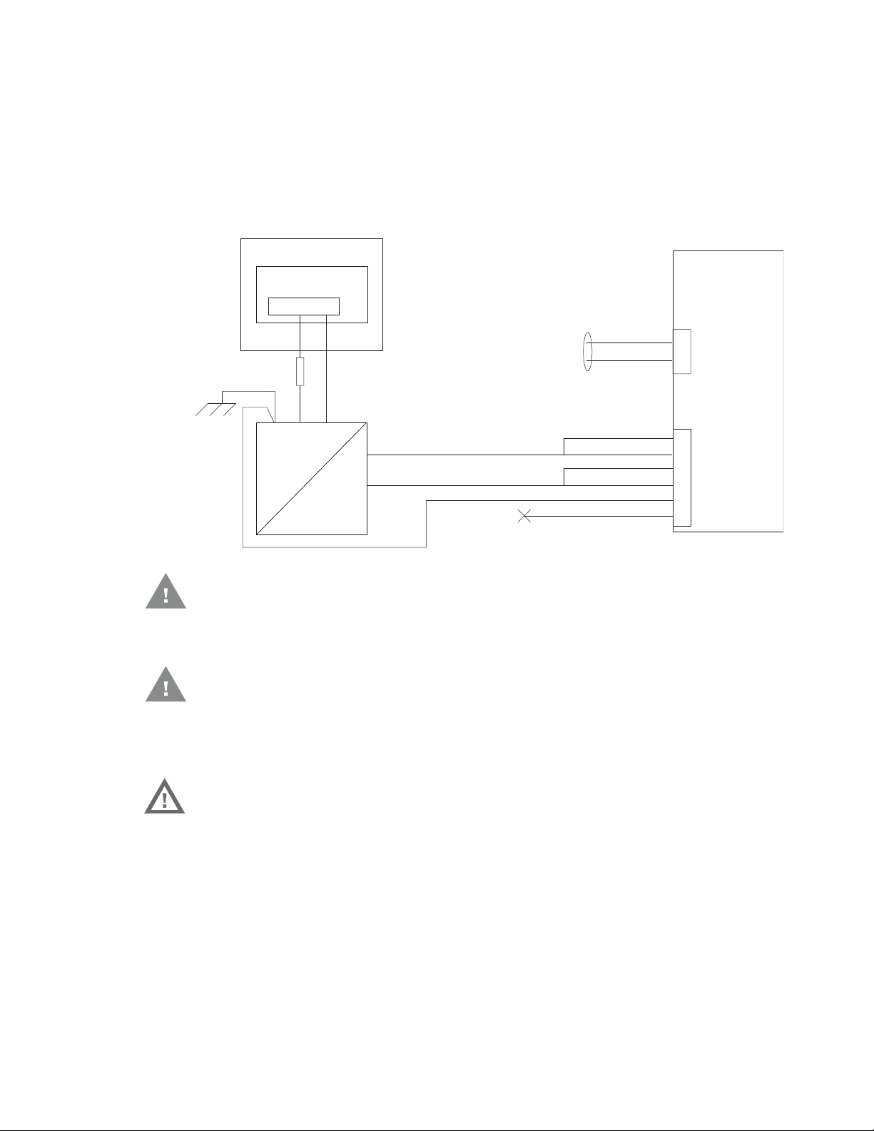
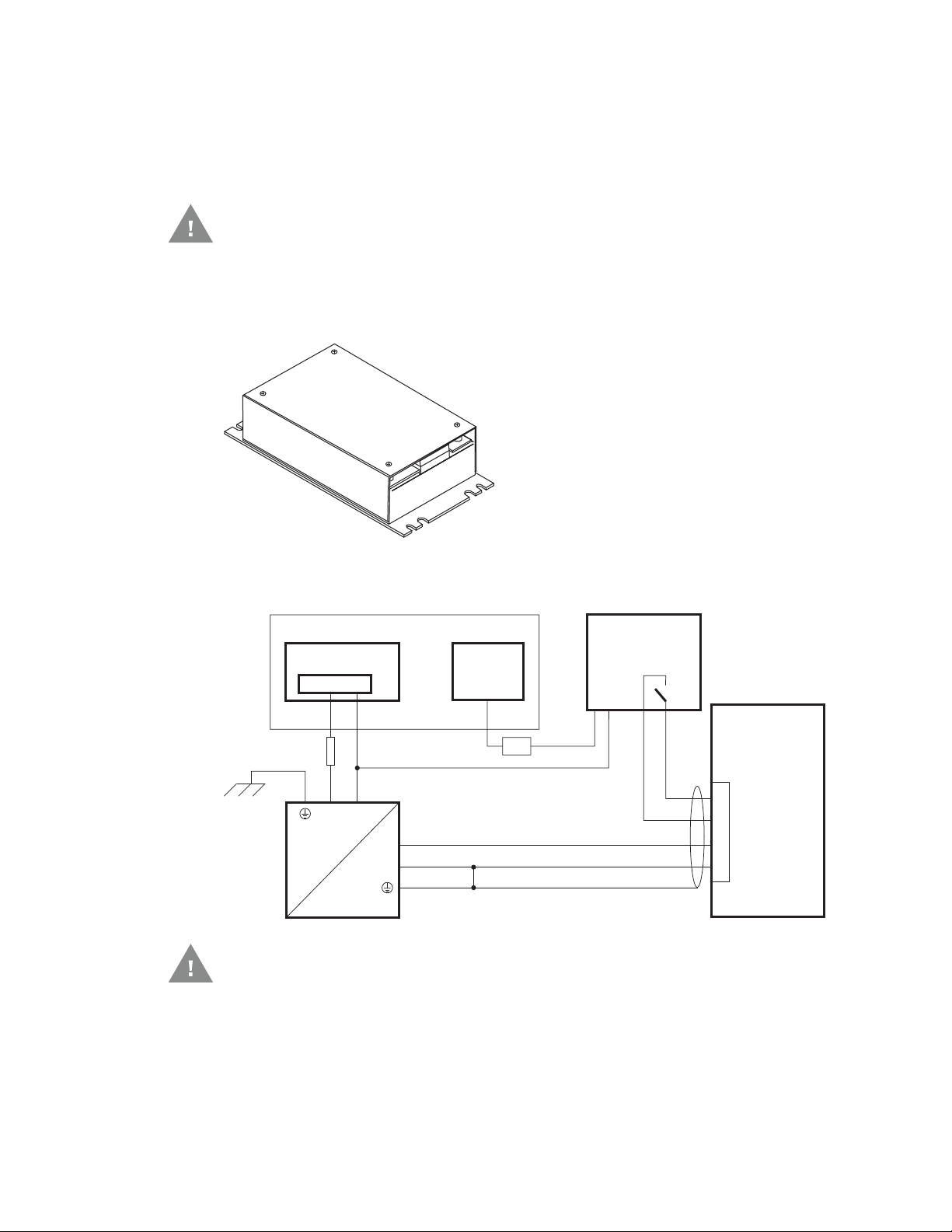
Main Switch
Circular
Power
Connector
on Dock
V
IN-
V
O-
-Vo
+Vo
COM1 or COM2
Connector
on Dock
VO+
V
IN+
GND
User supplied serial
cable for optional
screen blanking
connection,
see below
Existing Circuitry on Vehicle
Forklift Battery
DC/DC
Power
Supply
Fuse - See
Warning
statement below
See
Caution
statement
below
(not connected)
Black
Green
Blue
Red
Red/White (if present)
Black/White (if present)
Quick Mount
Smart Dock
Auto-On Behavior.
See the Auto-On control panel.
Note: Ignition control is not available for trucks over 60VDC.
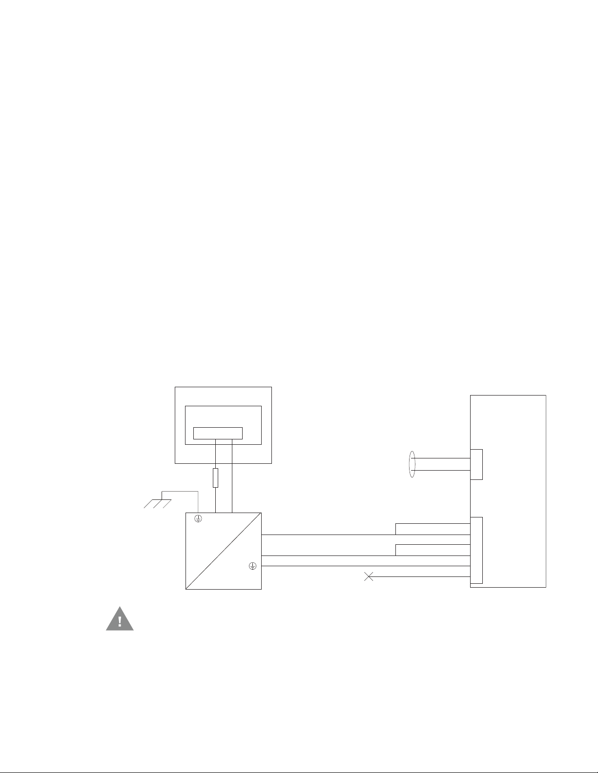
Wiring Diagram for 50-150VDC Power Supply, Screws on Side of Lid
Caution: For battery powered vehicles:
• GND must be connected to the vehicle chassis ground.
Caution: For internal combustion engine powered vehicles:
• GND is connected to the vehicle chassis ground, which can also be battery
negative.
Warning: For proper and safe installation, follow the Fuse Requirements 50-
150VDC Power Supply, Screws on Side of Lid.
Thor VM1A Vehicle-Mounted Computer 93
60-144 VDC Vehicles (50-150 VDC Power Supply, Screws on Top of
Lid)
Caution: These instructions are for use with VM1D Standard Dock and VM3D
Enhanced Dock only.
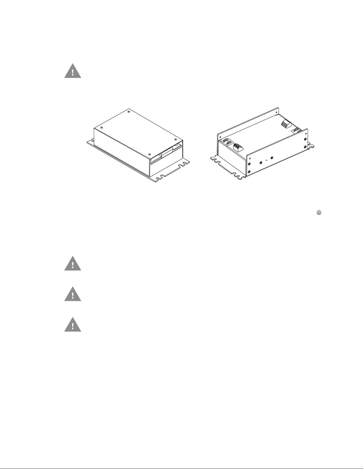
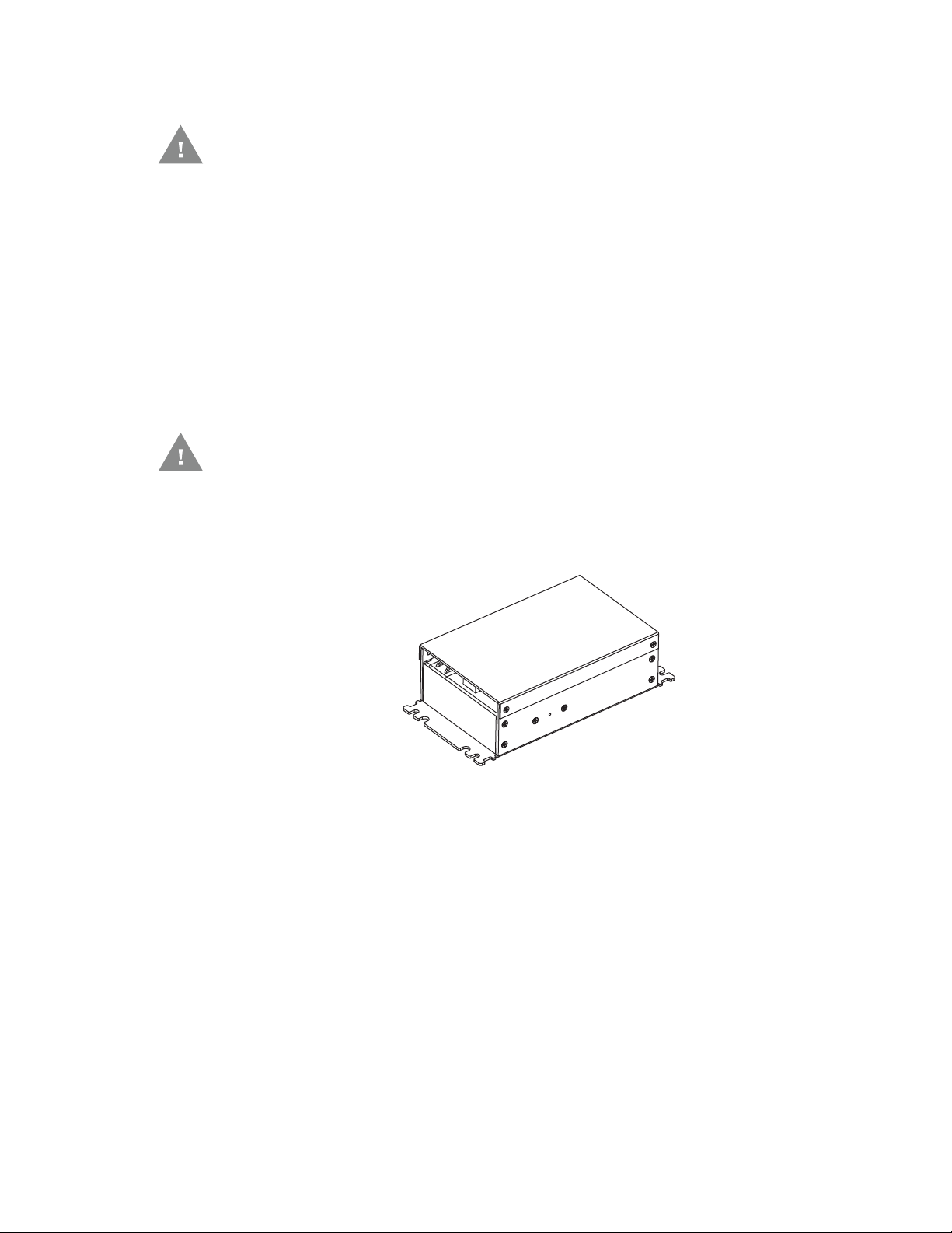
This option requires DC/DC power supply Honeywell Part no. VX89303PWRSPLY
shown below.
Shown with Lid Attached Shown with Lid Removed
Lid is secured with screws on the side of lid. Input and output connector blocks under lid.
Two positive (+), negative (-), and ground ( )
connection per terminal block.
If the DC/DC power supply does not have screws in the top of the lid, see 60-144
VDC Vehicles (50-150 VDC Power Supply, Screws on Side of Lid).
Caution: For installation by trained service personnel only.
Caution: Usage in areas where moisture can affect the power supply
connections should be avoided. The power supply should be mounted
in a dry location within the vehicle or placed in a suitable protective
enclosure.
Caution: Use caution when routing the power cable. See 12-48 VDC Vehicles
(10-60 VDC Direct Connection).
94 Thor VM1A Vehicle-Mounted Computer
Fuse Requirements for 50-150 VDC Power Supply, Screws on Top of Lid
Warning: For proper and safe installation, the input power cable must be
connected to a fused circuit on the vehicle. If the supply connection
is made directly to the battery, the fuse should be installed in the
positive lead within 5 inches of the battery’s positive (+) terminal. Use
VM3055FUSE (or equivalent) to install the fuse as shown below:
For all voltages, use the 3A fuse from the kit or a slow blow fuse that has a DC voltage rating greater than the vehicle input voltage.
Note: For North America, a UL Listed fuse is to be used.
Power Cable Identification for 50-150 VDC Power Supply, Screws on Top of Lid
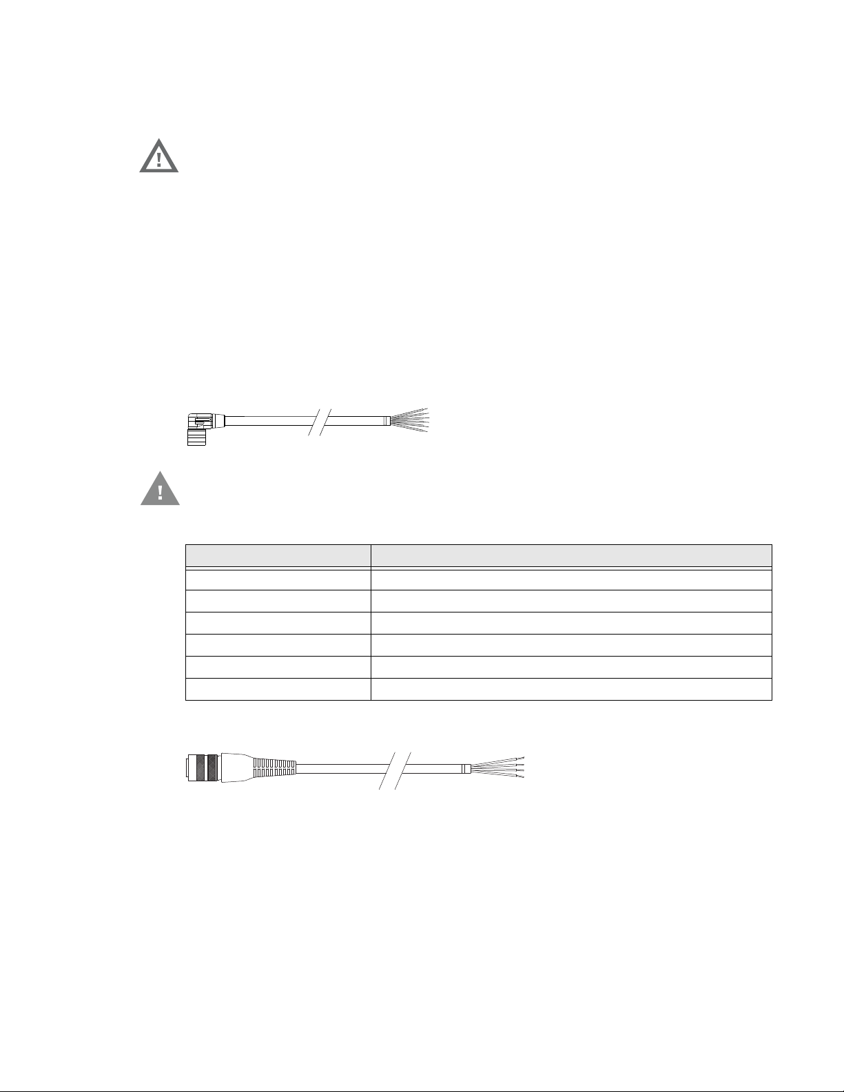
The DC power cable is included with the dock and is one of the two styles below:
Power cable with right angle connector and 6 wires:
Caution: Twist the red and red/white wires together and twist the black and
black/white wires together before connecting to vehicle power.
Wire Color Connection
Red DC + (10-60 VDC)
Red/White DC + (10-60 VDC)
Black DC -
Black/White DC -
Green Ground
Blue Ignition Input (optional)
Power cable with straight connector and 4 wires:
Thor VM1A Vehicle-Mounted Computer 95

Wire Color Connection
Red DC + (10-60 VDC)
Black DC -
Green Ground
Blue Ignition Input (optional)
Note: Correct electrical polarity is required for safe and proper installation. See the Wiring
Diagram for 50-150VDC Power Supply, Screws on Side of Lid for additional wire
color-coding specifics.
The Thor VM1A DC input wires (Red, Red/White DC+ and Black, Black/White DC-)
and the Blue ignition input wire are galvanically isolated. The Green ground input
is used for electrostatic discharge (ESD) protection.
Vehicle 50-150 VDC Power Connection
1. Please review the Wiring Diagram for 50-150 VDC Power Supply, Screws on Top
of Lid, before beginning power cable install.
2. The Thor VM1A must not be mounted in the dock. The power switch on the dock
must be turned Off. The power cable must be UNPLUGGED from the dock.
3. Route the cable from the computer to the DC/DC power supply. Route the
power cable the shortest way possible. The cable is rated for a maximum
temperature of 105°C (221°F). When routing this cable, it should be protected
from physical damage and from surfaces that might exceed this temperature.
Do not expose the cable to chemicals or oil that may cause the wiring insulation
to deteriorate. Always route the cable so that it does not interfere with safe
operation and maintenance of the vehicle.
4. Cut the cable to length and strip the wire ends.
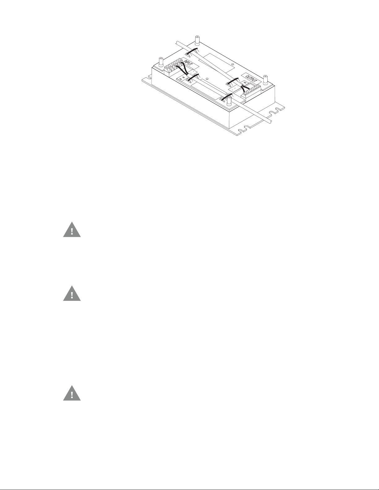
5. Remove the lid from the DC/DC power supply.
6. Connect the stripped end of the positive wires (red and red/white twisted
together or a single red wire) to the output block. See Power Cable Identification
for 50-150 VDC Power Supply, Screws on Top of Lid.
7. Connect the stripped end of the negative wires (black and black/white twisted
together or a single black wire) to the output. See Power Cable Identification for
50-150 VDC Power Supply, Screws on Top of Lid.
Note: The input and output blocks each have two + (positive), two – (negative) and two
(ground) connectors. Either connector in the block can be used to connect the
matching polarity wire.
96 Thor VM1A Vehicle-Mounted Computer
8. Route the wiring from the DC/DC power supply to the vehicle’s electrical
system. Do not connect to vehicle power at this time.
9. Strip the wire ends and connect to the input side of the DC/DC power supply.
10. Use looms and wire ties to secure all wiring as shown.
11. Reattach the cover with the screws.
12. Connect the DC/DC power supply to the vehicle’s electrical system as directed
below:
Caution: For battery powered vehicles:
•V
IN+ is connected to battery positive
•V
IN- must be connected to battery negative
• GND must be connected to the vehicle chassis ground
Caution: For internal combustion engine powered vehicles:
•V
IN+ is connected to battery positive
•V
IN- must be connected to battery negative
• GND must be connected to the vehicle chassis ground
13. While observing the Fuse Requirements, connect the power cable as close as
possible to the actual battery terminals of the vehicle. When available, always
connect to unswitched terminals in the vehicle fuse panel, after providing
proper fusing.
Caution: For uninterrupted power, electrical supply connections should not be
made at any point after the ignition switch of the vehicle.
14. Use proper electrical and mechanical fastening means for terminating the
cable. Properly sized “crimp” type electrical terminals are an accepted method
Thor VM1A Vehicle-Mounted Computer 97
of termination. Select electrical connectors sized for use with 18AWG (1mm
Power
Connector
-
-
-Vo
Black
Green
Blue
(not connected)
+Vo
COM1 or COM2
Connector
+
+
User supplied serial
cable for optional
screen blanking
connection,
see below
Existing Circuitry on Vehicle
Forklift Battery
Main Switch
Quick Mount
Smart Dock
DC/DC
Power
Supply
Fuse - See
Warning
statement below
Caution
Red
Red/White (if present)
Black/White (if present)
2
)
conductors.
15. Provide mechanical support for the cable by securing it to the vehicle structure
at approximately one foot intervals, taking care not to over tighten and pinch
conductors or penetrate the outer cable jacket.
16. Connect the watertight connector end of the power cable to the dock power
connector by aligning the connector pins to the power connector; push down
on the watertight connector and twist it to fasten securely. Flip the power switch
on the back of the dock to On.
17. Secure the power cable to the computer using the Strain Relief Cable Clamps.
18. Place Thor VM1A in the Dock.
19. If using the Screen Blanking feature, install the screen blanking box or switch.
20. Press the Power Switch on the back of the dock.
21. Press the Power Button on the front to turn on the computer.
Once installation is complete, remember to start the computer and configure the
Auto-On Behavior.
See the Auto-On control panel.
Note: Ignition control is not available for trucks over 60VDC.
Wiring Diagram for 50-150 VDC Power Supply, Screws on Top of Lid
See
statement below
Caution: For battery powered vehicles:
98 Thor VM1A Vehicle-Mounted Computer
•GND
To Power Connector on Dock
To VX6/VX7 Power Supply Cable
Caution: For internal combustion engine powered vehicles:
• GND is connected to the vehicle chassis ground, which can also be battery
Warning: For proper and safe installation, follow the Fuse Requirements for
must be connected to the vehicle chassis ground.
negative.
50-150 VDC Power Supply, Screws on Top of Lid.
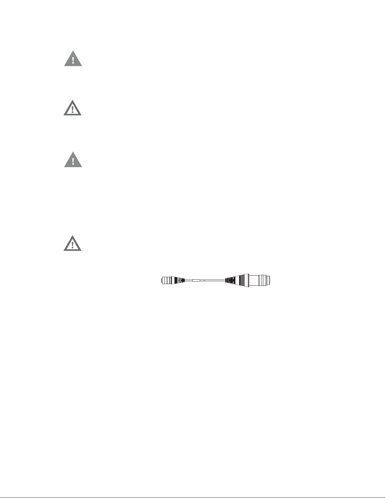
VX6/VX7 Adapter Cable
Caution: These instructions are for use with VM1D Standard Dock and VM3D
Enhanced Dock only.
An adapter cable is available to attach the Thor VM1A to a vehicle previously
equipped with a VX6/VX7 DC power cable. The adapter cable has a 5-pin connector
to match with the VX6/VX7 power supply cable on one end and a 6-pin connector
to match to the VM1A on the other end. This section assumes the VX6/VX7 power
cable is properly connected to vehicle power. Refer to the VX6 or VX7 Vehicle
Mounting Reference Guide for details.
Warning: Because the VX6/VX7 supports 10-60 VDC power input, verify input
voltages before using this adapter cable with an existing VX6 or VX7
power connection installation.
When this adapter cable is used, there is no provision for an ignition switch input.
Therefore the vehicle ignition monitoring function is not available when using this
cable.
Connect to VX6/VX7 Power Cable
1. Connect the adapter cable to the VM1A power cable by aligning the connector
pins to the power connector; push down on the watertight connector and twist
it to fasten securely.
2. The cable is rated for a maximum temperature of 105°C (221°F). Therefore,
routing this cable, it should be protected from physical damage and from
surfaces that might exceed this temperature. Cable should be protected from
physical damage from moving parts. Do not expose the cable to chemicals or
oil that may cause the wiring insulation to deteriorate. Always route the cable so
that it does not interfere with safe operation and maintenance of the vehicle.
Thor VM1A Vehicle-Mounted Computer 99
3. Provide mechanical support for the cable by securing it to the vehicle structure
To VX8/VX9
Power Cable
To COM port
on Dock
To Ground and
Ignition Sense
To Power Connector
on Dock
at approximately one foot intervals, taking care not to over tighten and pinch
conductors or penetrate outer cable jacket.
4. Connect the watertight connector end of the power cable to the dock power
connector by aligning the connector pins to the power connector; push down
on the watertight connector and twist it to fasten securely.
5. Secure the power cable to the computer using the Strain Relief Cable Clamps.
6. Place Thor VM1A in the Dock
7. If using the Screen Blanking feature, install the screen blanking box or switch.
8. Press the Power Switch on the back of the dock.
9. Press the Power Button on the front to turn on the computer.
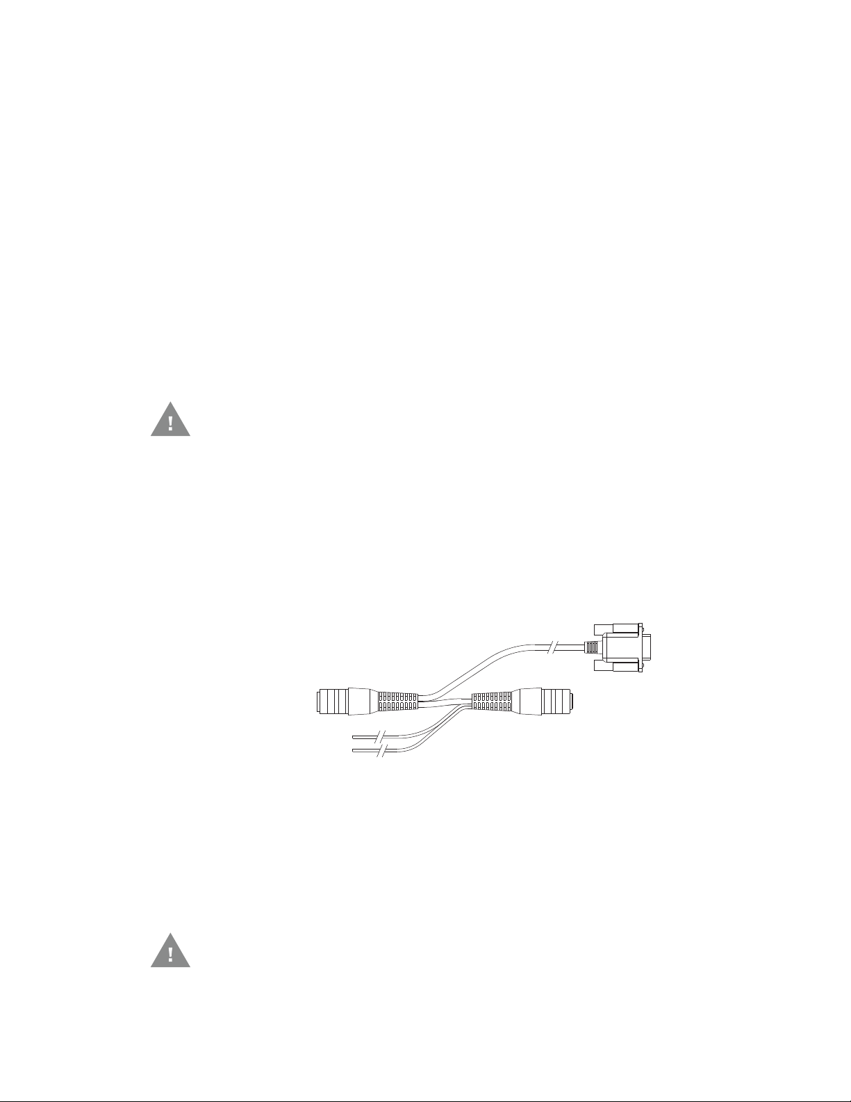
Thor VX8/Thor VX9 Adapter Cable
Caution: These instructions are for use with VM1D Standard Dock and VM3D
Enhanced Dock only. This cable is not used for the VMXD Enhanced
Dock.
An adapter cable is available to attach the Thor VM1A to a vehicle previously
equipped with a VX8/VX9 DC power cable. The adapter cable has a 6-pin connector
to match the VX8/VX9 power supply cable on one end and a 6-pin connector to
match the VM1A on the other end. The cable also has bare wires for ground and
ignition sense connection plus a D9 cable to connect to a COM port on the dock to
provide a screen blanking signal. This section assumes the VX8/VX9 power cable is
properly connected to vehicle power. Refer to the VX8 or VX9 Vehicle Mounting Reference Guide for details.
Connect to Thor VX8/VX9 Power Cable
1. Connect the adapter cable to the Thor VX8/VX9 power cable by aligning the
connector pins to the power connector; push down on the watertight connector
and twist it to fasten securely.
2. Connect the green wire to vehicle ground.
Caution: For battery powered vehicles:
100 Thor VM1A Vehicle-Mounted Computer

• GND (green wire) must be connected to the vehicle chassis ground.
Caution: For internal combustion engine powered vehicles:
• GND (green wire) is connected to the vehicle chassis ground, which can also
be battery negative.
3. If ignition control will be used, connect the blue wire to an ignition switched
circuit (less than 1mA over input voltage range). If ignition control is not used,
the blue wire can be left disconnected,
4. If the VX8/VX9 cable is connected to a screen blanking box or switch, connect
the D9 connector to a COM port on the dock.
5. The cable is rated for a maximum temperature of 105°C (221°F). Therefore,
when routing this cable, it should be protected from physical damage and from
surfaces that might exceed this temperature. Cable should be protected from
physical damage from moving parts. Do not expose the cable to chemicals or
oil that may cause the wiring insulation to deteriorate. Always route the cable so
that it does not interfere with safe operation and maintenance of the vehicle.
6. Provide mechanical support for the cable by securing it to the vehicle structure
at approximately one foot intervals, taking care not to over tighten and pinch
conductors or penetrate outer cable jacket.
7. Connect the watertight connector end of the power cable to the dock power
connector by aligning the connector pins to the power connector; push down
on the watertight connector and twist it to fasten securely.
8. Secure the power cable to the computer using the Strain Relief Cable Clamps.
9. Place Thor VM1A in the Dock.
10. If using the Screen Blanking feature, install the screen blanking box or switch if
not previously installed.
11. Press the Power Switch on the back of the dock.
12. Press the Power Button on the front to turn on the computer.
CV61 Adapter Cable
Caution: These instructions are for use with VM1D Standard Dock and VM3D
Enhanced Dock only.
An adapter cable is available to attach the Thor VM1A to a vehicle previously
equipped with a CV61 DC power cable. The adapter cable has a 5-pin connector to
match with the CV61 power supply cable on one end and a 6-pin connector to
match to the VM1A on the other end. This section assumes the CV61 power cable is
properly connected to vehicle power. Refer to the CV61 documentation for details.
Thor VM1A Vehicle-Mounted Computer 101

When this adapter cable is used, there is no provision for an ignition switch input.
To Power Connector on Dock
To CV41 Power Supply Cable
Therefore the vehicle ignition monitoring function is not available when using this
cable.
Connect to CV61 Power Cable
1. Connect the adapter cable to the CV61 power cable by aligning the connector
pins to the power connector; push down on the watertight connector and twist
it to fasten securely.
2. The cable is rated for a maximum temperature of 105°C (221°F). Therefore,
routing this cable, it should be protected from physical damage and from
surfaces that might exceed this temperature. Cable should be protected from
physical damage from moving parts. Do not expose the cable to chemicals or
oil that may cause the wiring insulation to deteriorate. Always route the cable so
that it does not interfere with safe operation and maintenance of the vehicle.
3. Provide mechanical support for the cable by securing it to the vehicle structure
at approximately one foot intervals, taking care not to over tighten and pinch
conductors or penetrate outer cable jacket.
4. Connect the watertight connector end of the power cable to the dock power
connector by aligning the connector pins to the power connector; push down
on the watertight connector and twist it to fasten securely.
5. Secure the power cable to the computer using the Strain Relief Cable Clamps.
6. Place Thor VM1A in the Dock
7. If using the Screen Blanking feature, install the screen blanking box or switch.
8. Press the Power Switch on the back of the dock.
9. Press the Power Button on the front to turn on the computer.
Screen Blanking
Screen blanking (blackout) can be enabled when the vehicle is in motion. Once
screen blanking is enabled, the display is blanked out (or a preselected zoom area
is displayed) any time when the cable sends the signal that the vehicle is in motion.
If the cable is removed, screen blanking is disabled and the display remains on.
Prerequisite: The steps outlined in either 12-48 VDC Vehicles (10-60 VDC Direct
Connection), 60-144 VDC Vehicles (50-150 VDC Power Supply, Screws on Side of
Lid) or 60-144 VDC Vehicles (50-150 VDC Power Supply, Screws on Top of Lid)
have been completed.
102 Thor VM1A Vehicle-Mounted Computer

Screen blanking is accomplished by either a Screen Blanking Box or a user supplied switch.
Caution: For installation by trained service personnel only.
Fuse Requirements for Screen Blanking
Warning: For proper and safe installation, the input power lead to the
Screen Blanking Box requires a 3 Amp maximum time delay
(slow blow) high interrupting rating fuse.
Note: For North America, a UL Listed fuse is to be used.
Screen Blanking Cable
Refer to Screen Blanking to configure the VM1A for screen blanking.
When routing any additional cables for screen blanking:
• Route the cable the shortest way possible removing any left-over cable
• Fuses and cabling are user supplied. Therefore, route these cables so they are
protected from physical damage and from surfaces that might exceed the
cable's rated temperature threshold.
• Cable should be protected from physical damage from moving parts
• Do not expose the cable to chemicals or oil that may cause the wiring insulation
to deteriorate
• Always route the cable so that it does not interfere with safe operation and
maintenance of the vehicle.
• Provide mechanical support for the cable by securing it to the vehicle structure
at approximately one foot intervals, taking care not to over tighten and pinch
conductors or penetrate outer cable jacket.
Honeywell Screen Blanking Box Cable
An optional Honeywell Screen Blanking Box Cable is available.
Thor VM1A Vehicle-Mounted Computer 103
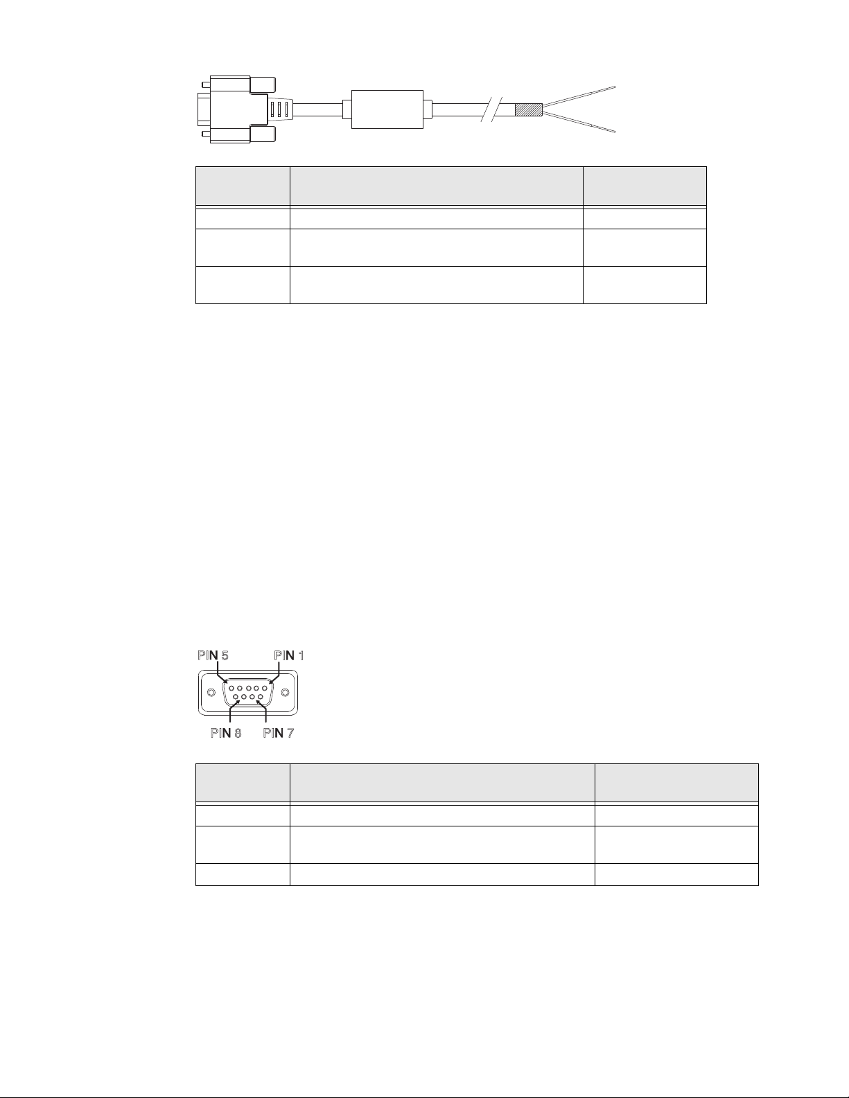
DB9
PIN7
PIN 8
PIN 5
PIN1
Female
1 -6, 9 Not Used
7 (RTS) Connected to Screen Blanking Box, unswitched
8 (CTS) Connected to Screen Blanking Box, switched
Function with Screen Blanking Box Wire color
side
side
Note: Wire colors only apply to optional Honeywell Screen Blanking Box Cable,
VM1080CABLE. Wire colors may vary in a user-supplied cable.
The optional Honeywell Screen Blanking Box Cable, VM1080CABLE, is installed as
follows:
1. Connect the gray wire of the cable to the switched side of the Screen Blanking
Box.
2. Connect the black wire of the cable to the unswitched side of the Screen
Blanking Box.
3. Connect the D9 serial connector to either COM1 or COM2 serial port on the
dock.
User-Supplied Cable for Screen Blanking
Black (see note)
Gray (see note)
A user-supplied cable can be used as well. Pins 7 and 8 must be connected as
detailed below. No other pins are to be connected.
DB9
Female
1 -6, 9 Not Used Not Used
7 (RTS) Connected to Screen Blanking Box, unswitched
8 (CTS) Connected to Screen Blanking Box, switched side Connected to Switch
Function with Screen Blanking Box Function with Switch
Connected to Switch
side
The user-supplied cable is installed as follows:
104 Thor VM1A Vehicle-Mounted Computer

1. Connect the wire from Pin 8 of the cable to the switched side of the Screen
Unswitched Switched
Blanking Box or to a user-supplied switch.
2. Connect the wire from Pin 7 of the cable to the unswitched side of the Screen
Blanking Box or to a user-supplied switch.
3. Connect the D9 serial connector to either COM1 or COM2 serial port on the
dock.
Screen Blanking Box
Screen Blanking
Box Terminal
12-xxV Input from vehicle motion sensing circuitry.
GND DC -
Connection
Please refer to label on Screen Blanking Box for allowable voltage input
range.
These two terminals are for connecting a serial cable:
• If using an optional Honeywell screen blanking cable, VM1080CABLE,
connect the gray wire to the switched side of the connection and connect
the black wire to the unswitched side.
• If using a user-supplied cable, the cable must be constructed so that Pin
7 (RTS) connects to switched side of the connection and Pin 8 (CTS)
connects to the unswitched side.
It is assumed that the motion sensing circuitry in the illustrations below is powered
by internal vehicle circuitry.
Please refer to the appropriate illustration below for Screen Blanking Box wiring
diagrams.
Warning: Do not exceed the maximum input voltage, either 60 or 72VDC,
specified on the Screen Blanking Box label when using this
configuration.
Thor VM1A Vehicle-Mounted Computer 105

Note: The black and gray wire colors in the illustration only apply to the optional Honeywell
MOTION
CIRCUITRY
To
-Vo on vehicle,
i.e. Negative
battery terminal
3A fuse
+V
i
GND
To pin 7 of COM1 or
COM2
To pin 8 of COM1 or
COM2
To pins 7 and 8
of COM1 or
port on dock
Screen Blanking Box Cable, VM1080CABLE. The wire colors may be different in a
user-supplied cable.
Screen Blanking with Switch
In applications where it is impractical to use the screen blanking box due to vehicle
voltage or lack of a motion sensing signal, screen blanking can be controlled via a
user supplied switch or relay that provides an electrical conductive connection on
vehicle motion.
COM2
Pins 7 and 8 must be connected as shown in the illustration above. No other pins
are to be connected.
106 Thor VM1A Vehicle-Mounted Computer

VMXD Enhanced Dock with Thor VX8/Thor VX9 Power Cable
Caution: This dock is recommended for use when replacing an existing Thor
VX8 or Thor VX9 where screen blanking is used. This dock eliminates
the need for wiring changes by enabling the existing VX8/VX9 power
cable and screen blanking box to be used when the VX8/VX9 is
replaced by Thor VM1A These instructions are for this doc model
only! The Ignition Control feature is not available when this dock is
used.
Warning: The external DC/DC converter previously used with the Thor VX8 or
Thor VX9 must be left in place to provide ground isolations.
Connecting the dock power input directly to vehicle power could
result in a safety hazard or equipment damage.
Warning: The cable shielding must be connected to chassis ground. Consult
the instructions later in this section for the respective power supply
type.
Caution: COM1 is used for screen blanking (via the power cable connector) and
is unavailable when the screen blanking box is attached. When a
screen blanking box is attached, any external serial device, such as a
scanner, must be connected to the COM2 port on the dock. If a screen
blanking box is not connected via the power cable, the COM1 port on
the dock is available for a serial device connection.
Caution: These instructions for use with VMXD Enhanced Dock only.
Determine the type of power supply used with the previous Thor VX8 or Thor VX9
installation:
• DC/DC Power Supply with Screws on Top of Lid
• DC/DC Power Supply with Screws on Side of Lid
Thor VM1A Vehicle-Mounted Computer 107
DC/DC Power Supply with Screws on Top of Lid
Circular
Power
Connector
DC/DC
Power
Supply
Supplied Power Cable
(Shielding to be trimmed)
5
6
1
3
Green
Yellow
Brown
White
Existing Circuitry on Vehicle
Forklift Battery
-Vo
+Vo
10A slow fuse
Close to power
source
Main Switch
VMX004VMCRADLE
Vehicle Mount
Smart Dock
-
+
-
+
MOTION
CIRCUITRY
3A fuse
+Vi
GND
Caution: Inspect the cable shield to verify it is connected to chassis ground. If
there is no connection from the cable shield to chassis ground, one
must be added at this time. Use a jumper wire to connect the cable
shield to chassis ground as shown below for the appropriate type of
power supply installed on the vehicle. A jumper wire, as shown in the
illustrations below, may be present to attach the chassis ground to
the white wire of the power cable. This wire is not necessary but can
be left in place if present. For proper screen blanking, verify the
yellow and green wires are attached to the screen blanking box as
shown in the illustrations below.
For this model, follow the diagram below to attach the power cable shield to chassis ground:
Caution: For battery powered vehicles:
•V
IN+ is connected to battery positive.
•V
IN- must be connected to battery negative.
108 Thor VM1A Vehicle-Mounted Computer
• GND must be connected to the vehicle chassis ground.
Caution: For internal combustion engine powered vehicles:
IN+ is connected to battery positive.
•V
•V
IN- is connected to battery negative.
• GND is connected to the vehicle chassis ground, which can also be battery
negative.
DC/DC Power Supply with Screws on Side of Lid
Caution: Inspect the cable shield to verify it is connected to chassis ground. If
there is no connection from the cable shield to chassis ground, one
must be added at this time. Use a jumper wire to connect the cable
shield to chassis ground as shown below for the appropriate type of
power supply installed on the vehicle. A jumper wire, as shown in the
illustrations below, may be present to attach the chassis ground to
the white wire of the power cable. This wire is not necessary but can
be left in place if present. For proper screen blanking, verify the
yellow and green wires are attached to the screen blanking box as
shown in the illustrations below.
Thor VM1A Vehicle-Mounted Computer 109
 Loading...