

Page 1
PRODUCT HANDBOOK
1 EN2R-9004 0606R20-NE
Subject to change without notice. All rights reserved.
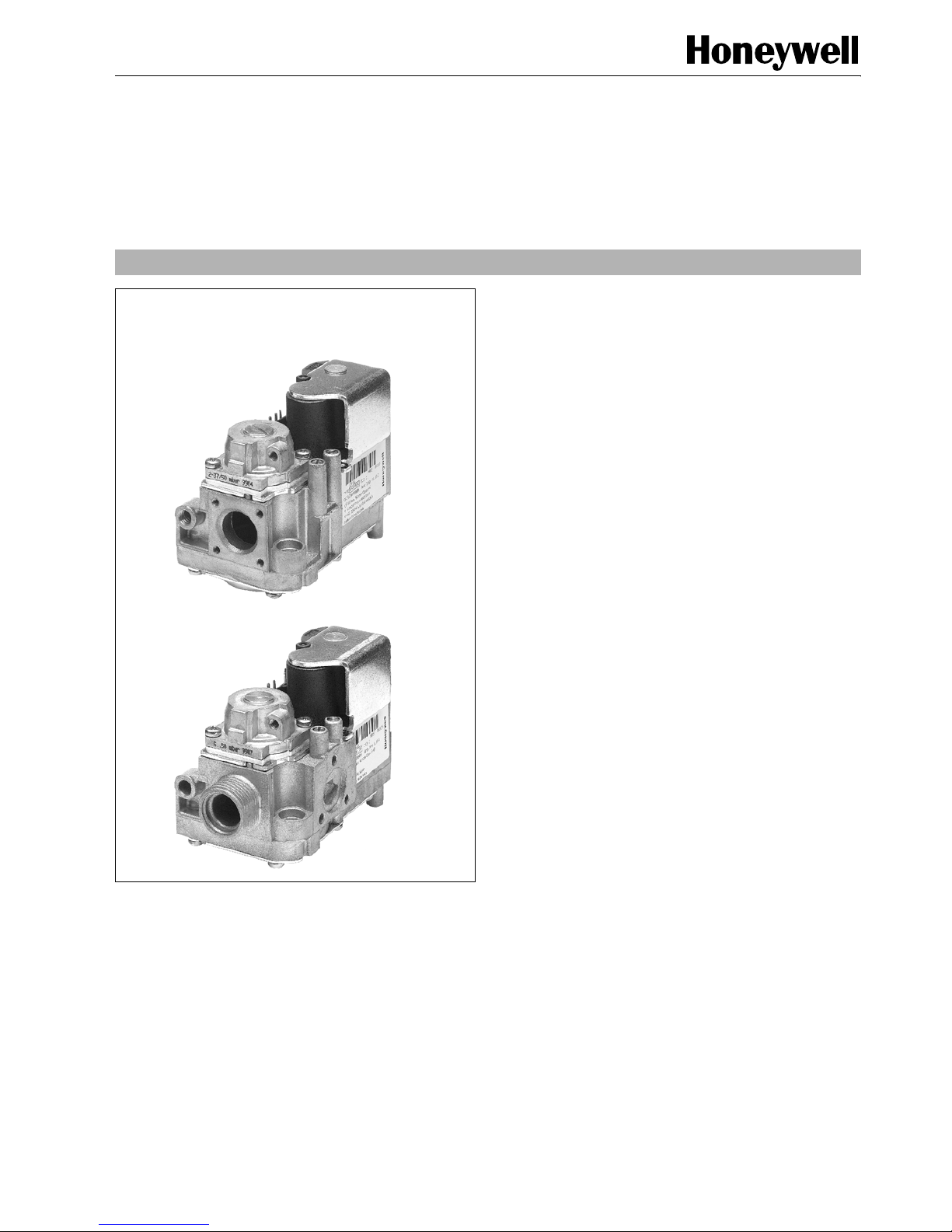
VK41../VK81..SERIES
GAS CONTROLS FOR COMBINED VALVE AND IGNITION SYSTEM
APPLICATION
The Combined Valve and Ignition (CVI) system has been
developed for application in gas fired domestic central heating
boilers, combi boilers and warm air furnaces or water heater
appliances with an automatic ignition system.
For this system, the VK41../VK81.. series gas controls have
been designed to have the S4565/S4575/S4585 series
ignition control attached directly on to the valve.
The combined system then provides programmed safe light
up, flame supervision and regulation of gas flow to the main
burner and/or pilot burner of the appliance.
The VK41.5/VK81.5 series gas controls (without pilot outlet)
can also be used alone in direct burner ignition applications.
A plug (order number 45.900.441- ) with integrated rectifier
circuit then has to be used on the gas control.
Contents
General page
Description ...................................................................... 2
Features .......................................................................... 3
Dimesional ..................................................................... 4
Application ...................................................................... 6
Technical
Specifications .................................................................. 7
Electrical data .............................................................. 10
Capacity curves ....................................................... 13-18
Performance characteristics .......................................... 19
Installation ..................................................................... 21
Electrical connections and wiring .................................. 24
Adjustments and checkout ............................................ 25
Construction and working principles ............................. 26
Various
Quality assurance statement ......................................... 29
Standards and approvals .............................................. 30
Ordering information ..................................................... 31
Replacement parts and accessories ............................. 32
Page 2

EN2R-9004 0606R20-NE 2
DESCRIPTION
Valves
The Combined Valve and Ignition (CVI) system controls and
performs all the functions required for safe ignition, flame
supervision and for safely regulating the gas flow to the pilot
and/or main burner.
The CVI consists of a gas valve of the VK41../VK81.. series
and a dedicated ignition control of the series S4565/S4575/
S4585 which is connected directly on to it.
The gas control comprises a standard body to which a range
of features can be factory included to give various functional
options. These functional options include: servo pressure
regulation, throttle valve regulation, fully adjustable
SOFTLITE,
gas/air control 1:1 or amplified, electrical high-low or
modulating control to fulfil the complete range of control
applications.
The gas control has a first direct on/off operator for opening
the safety valve of class B according to EN 161 and a second
electric on/off servo operator for control of the main valve of
class B,C or J according to EN 161 (for explanation class J,
see chapter Standards and approvals page 30).
The pressure regulator is in accordance with class B
requirements of EN 88
The gas control can handle the three gas families,
manufactured gas, natural gas and LP gas.
General
All measurements are carried out under standard conditions
listed below unless otherwise is indicated.
Standard conditions
• P
inlet
25 mbar nominal pressure, dry air of 20°C
• P
ambient
1013 mbar
• T
ambient
20°C
• Outlet orifice 2.8 mm
• Flow indication in m
3
/
h
• Recording of outlet pressure with a transducer connected
to a
1
/2” pipe with a length of 10 times the diameter of the
pipe with a short hose at a length of 5 times the diameter of
the pipe.
• Nominal voltage
• Upright position, i.e. the position when the operators are on
top.
Page 3

3 EN2R-9004 0606R20-NE
FEATURES
General
• All burner control safety functions concentrated in one reliable and optimized system.
• Specially designed to provide the optimum system solution
in gas appliances with a DBI or IP system to light the main
burner.
• Both gas control and ignition control incorporate time
proven design concepts assuring reliability.
• ON/OFF control of main burner by electric operator and
electric servo operator directly energized from ignition control.
• Easy assembly of ignition control on gas control by plugging it on from the top.
• Mounting orientation may be within 90
°
in any direction
from the electric on/off operator upright position.
Gas control
• Inlet ∅ 18.6 mm and outlet ∅ 18.6 mm connections are
straight through and can receive flanges.
• The following closing force models are available: B + J;
B + C; B + B.
• Servo pressure regulator provides stable outlet pressure.
• Pressure feedback ensures constant burner pressure in
relation to combustion chamber pressure.
• All adjustments are accessible from the top.
• 9 mm diameter pressure taps on top face for checking inlet
and outlet pressure
• An internal fine mesh screen is incorporated at the inlet of
the gas control. This screen is not removable for cleaning.
• An outlet screen is optional.
• Two mounting holes for self tapping screws are at the bot-
tom of the gas control for rigid attachment to the appliance.
Functional options
• Fast open and SOFTLITE versions
• Fully adjustable
SOFTLITE option to facilitate the smooth
light-up of burner and for changing over from one gas to
another.
NOTE:
SOFTLITE opening is not always available when the
second valve is classified as a class B valve.
• 100 mbar inlet pressure versions available on request
• Throttle valve versions
• Electrical modulation (Modureg) or CVI-m.
• Electrical High-Low control.
• Pilot outlet for IP system
• Gas/Air ratio version available.
Gas connection options
• Internal thread (ISO 7-1), external thread (ISO-R228) or
flanged connections. See table 4, 5, 6 and 7, page 9.
• Side outlet option for both main and pilot gas.
• The side outlet for pilot and main gas can only be con-
nected to a flanged burner manifold.
• Pilot gas connection for tubing with 4 mm outer diameter is
located at the outlet end of the gas control.
• Pressure feedback fittings for 4 or 6 mm silicon tube can be
mounted.
• End outlet or side outlet
Quick connection for Mini Venturi
Electrical connection options
• The appropriate ignition control can be connected to the
valve by plugging it on.
• Wired plug (IP 40) for connection with a remote ignition
control.
• Rectifier plug (IP 40) for use with any standard DBI ignition
system.
• 24 Volt versions available for use in conjunction with other
ignition controls than S4565/S4585 series.
Page 4
EN2R-9004 0606R20-NE 4
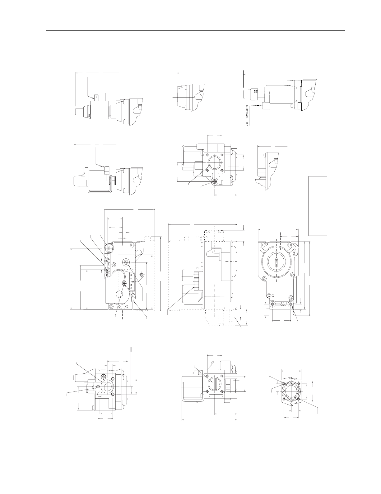
DIMESIONAL DRAWING STANDARD CONNECTION
13.4
Pilot outlet M8 x 1-6H
for 4 mm tubing
24
Outlet
29.3
36.7
6.3 terminal (3)
148
VK.1..P/Q
(High/Low)
VK.1..A/C
(Standard regulator)
80
VK.1..E/T
(Throttle)
70
6.3 terminal (2)
148
VK.1..M/N
(Modureg)
24
Side outlet
Pressure tap (2)
Adjustable softlite
94.8
68.3
1
6
24.9
84.5
73
84.5
115
STEP
STEP
Hole Ø 2.6 to connect
ignition control
Throttle
Molex 1.1 square pin header
(mating connectors 3001 series)
113
17
12.5
25
Flange thread 1/2"
or 3/8" ISO7-1
16 mm full thread
VK.1..B/D
(Blank plate)
115
105
8
18
30
29.4
64.9
Mounting hole (2) for
tapping screws 3.9
DIN 7970
36.7
24.1
24
68.3
34.3
9.1
"0"-ring size
Ø 15.55 x Ø 15.55
M5 x 0.8(3)
6 mm full thread
Side outlet
(Optional)
Inlet
24
91
36.7
M4x0.7-6H(8)
6 min full thread
12
24
32
Ø 18.6
The cross hatched area
is sealing face without
imperfections
32
24
12
OUT
Earth terminal
21.9
IN
62
V1 V2
Tolerances according
to ISO 2768 mK
24
VK.1..M/N
(ModuPlus)
140
Page 5
5 EN2R-9004 0606R20-NE
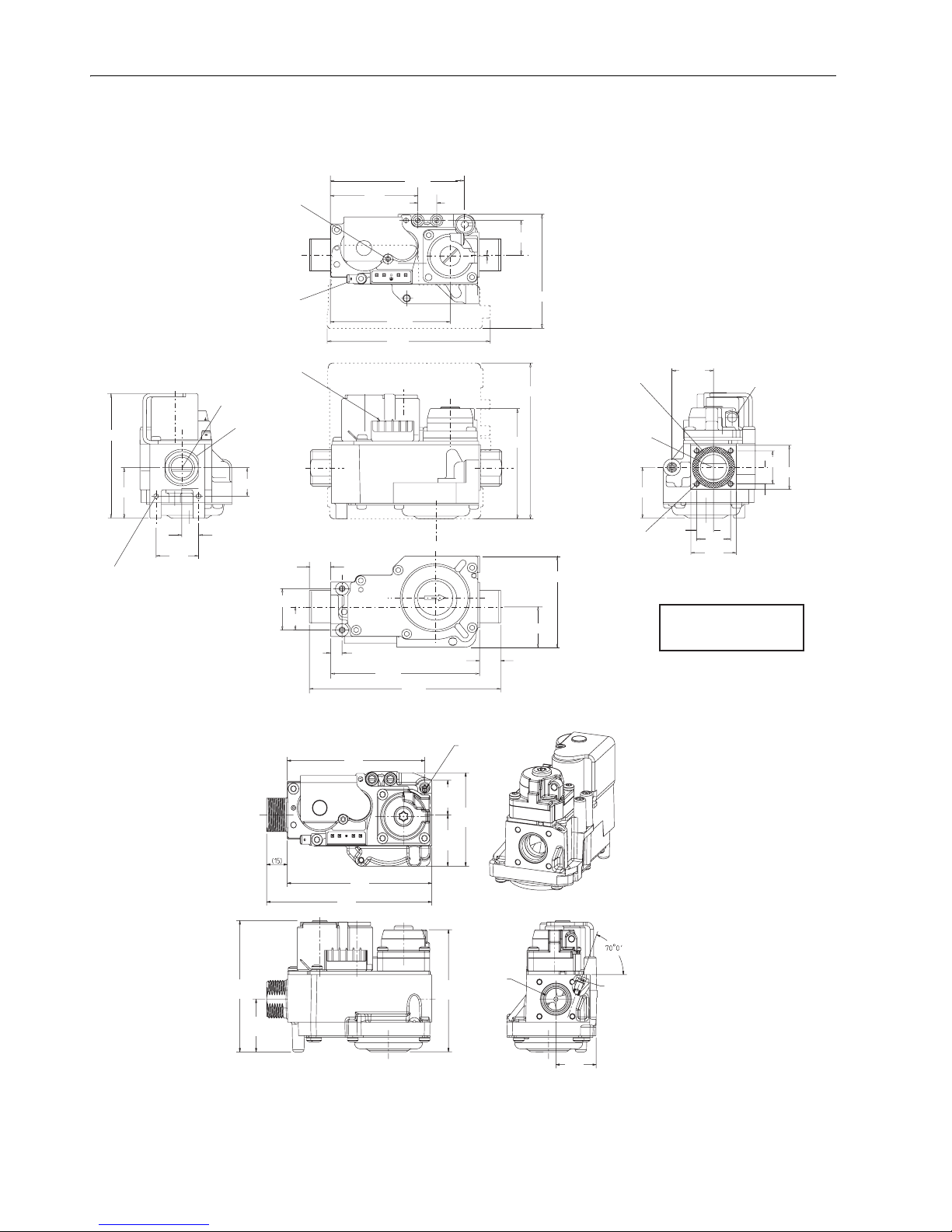
DIMESIONAL DRAWING EXTERNAL THREAD CONNECTION
Dimensional drawing VK41.5VE/VK81.5VE (Throttle)
8
15 ref
135
105
29.4
64.9
15
15
30
11.9
36.7
91
Inlet
20.7
30
G1/2" or
G
3/4
"
13.4
1
OUT
MIN
V1 V2
IN
84.5
115
62
24.9
84.5
Hole Ø 2.6 to connect
ignition control
Earth terminal
94.8
24
12
32
24
Pressure feedback
connection
29.3
36.7
32
12
End outlet
The cross hatched
area is sealing face
without imperfections
80
113
Molex 1.1 square pin header
(mating connecters 3001 series
Mounting hole (2) for tapping
screws 3.9 according DIN 7970
Tolerances according
to ISO 2768 mK
100
120
105
85
91
36,7
65
35,7
24,1
Throttle
Throttle screw
Throttle screw
29,3
Page 6

EN2R-9004 0606R20-NE 6
APPLICATION
The VK41.. /VK81..series gas control have been specially
developed for application in domestic appliances.
The VK41.. series gas control can be used in a system in
conjunction with a S4565, S4575 or S4585 series ignition
control to provide an optimised safety sub-system for
programmed safe light-up and flame supervision of the main
burner.
When connected with a Honeywell specified rectifier plug and
lead the VK4105 series valve can be used with any standard
220/240 Vac DBI ignition system.
VK81.. series gas controls for 24 Vrac have been developed
for application with other ignition controls with appropriate
power supply.
Page 7
7 EN2R-9004 0606R20-NE
SPECIFICATIONS
NOTE: Specifications for electrical modulation, electrical
high low, gas/air and other features are available on
request.
Models
See model number chart on page 31
Main gas connection
• Standard see table 4, page 9.
• Optional see table 5, page 9.
• Side outlet can be fitted direct to a flanged burner manifold.
Inlet and outlet with
3
/8” or 1/2” ISO 7-1 internal pipe thread
and straight or elbow flanges with
3
/8” or 1/2” ISO 7-1 internal
pipe thread are according to the torsion and bending stress of
EN126 group 2
Connections with G
1
/2” or G 3/4” external thread fitted with
nuts according to ISO 228-1 in combination with applicable
sealing(s) withstand the torsion and bending stress of EN 126
group 1
Ambient temperature
-15 ... 60°C
Humidity
95% RH max. at 40°C
Storage
- 30 ... 70°C
Pilot gas connection
Standard at end outlet: M8 x 1 for 4 mm outer diameter tubing.
Pressure feedback connection
The servo pressure regulator has an M5 thread connection for
pressure feedback.
Pressure feedback fittings for 4 or 6 mm silicon tube can be
mounted as option.
Dime nsions
See page 4 and 5
Outlet pressure range for ON/OFF regulators
1.5 ... 20 mbar
2 ... 37 mbar
5 ... 50 mbar
Minimum regulation capacity
0.31 m3/h air
Minimum differential pressure
Maximum operating pressure
The P
max
indication on the housing of the gas control is the
maximum pressure at which it functions safely.
However, the maximum inlet pressure is limited by the
pressure range of the pressure regulator concerned.
(See table 2.)
* This type can also be used for non regulation mode in LP
applications when pressure regulator adjustment screw is
clockwise turned down until it stops.
Versions up to 100 mbar maximum inlet pressure are available
on request
Mounting holes
Two mounting holes for thread forming M4 screws are located
on the bottom of the gas control.
For versions with external thread there are two additional
mounting holes for thread forming screws at the inlet side of
the gas control.
The four holes at inlet and outlet for mounting a flange on the
gas control are provided with M4 thread with min. 6 mm full
thread.
In case of side outlet the three holes for mounting the flange
are provided with M5 thread with a minimum of 6 mm full
thread.
Table 1: Minimum differential pressure
Model ∆P min (mbar)
VK4105 2.5
VK4115 4
VK4125 4
Table 2: Operating pressure
Model Pressure range
(mbar)
Maximum inlet
pressure (mbar)
with regulation 1.5 ... 20
2 ... 37*
5 ... 50*
30
45
60
without regulation - 60
Page 8
EN2R-9004 0606R20-NE 8
Capacity
In m3/h air at pressure drop as shown below. See also the capacity curves concerned.
NOTE 1.: Versions with side outlet connection have a 0.2 m
3
/h air lower capacity.
NOTE 2.: Increased capacity versions are optional for types with suffix letter E, T and V.
NOTE 3.:
3
/4“ external thread versions have a 0.3 m3/h air lower capacity.
Model Extention ∆P (mbar) Capacity (m3/h air) Capacit y curve
Number Page
VK410X/VK810X A, B, C, D, M, N, P, Q 3 3.4 H 10 13
E, T 3 2.8 H 160 17
VK411x/VK811x A, B, C, D, M, N, P, Q 5 4.4 H 20 14
E, T 5 3 H 170 18
V, VE 5 3.4 H 140 15
10 5.1
VB 5 4.4 H 20 14
VK412X A, B, C, D, M, N, P, Q 5 2.2 H 150 16
VK412X /VK812X V 5 2.2 H 150 16
10 5.1
Table 3: Valve classification
Model
1
st
valve 2nd valve
Classification Backpressure (mbar) Classification Backpressure (mbar)
VK4100/VK4105
VK8100/VK8105
B50J 0
VK4110/VK4115
VK8110/VK8115
B50C10
VK4120/VK4125
VK8120/VK8125
B50B50
Page 9
9 EN2R-9004 0606R20-NE
Table 6: Mini-Venturi valve connection
Table 7: Throttle valve (VK....VE only) connection
Table 4: Standard valve connection
Inlet End outlet Side outlet Body length
(mm)
Flanged Flanged -- 105
Flanged -- Flanged 105
Internal
3
/8”
ISO 7-1
-- Flanged 115
Internal
1
/2”
ISO 7-1
-- Flanged 115
Internal
1
/2”
ISO 7-1
Internal 1/2”
ISO 7-1
-- 115
Table 5: External valve connection (optional)
Inlet End outlet Side outlet Body length
(mm)
G
1
/2”G
1
/2”-- 135
G
1
/2” Flanged -- 120
G
3
/4”G
3
/4”-- 135
G
3
/4” Flanged -- 120
G
3
/4” -- Flanged 120
G
3
/4” Internal 11/2”
ISO 7-1
-- 120
G
1
/2” -- Flanged 120
Flanged G
1
/2”-- 120
Flanged G
3
/4”-- 120
Inlet End outlet Side outlet Body
length
(mm)
Flanged Quick connect
mini-venturi
-120
Flanged - Quick connect
mini-venturi
105
G
3
/4” Quick connect
mini-venturi
-135
G
3
/4” - Quick connect
mini-venturi
120
Inlet End outlet Side outlet Body length
(mm)
Flanged Flanged -- 105
G
1
/2” Flanged -- 120
G
3
/4” Flanged -- 120
Page 10
EN2R-9004 0606R20-NE 10
ELECTRICAL DATA
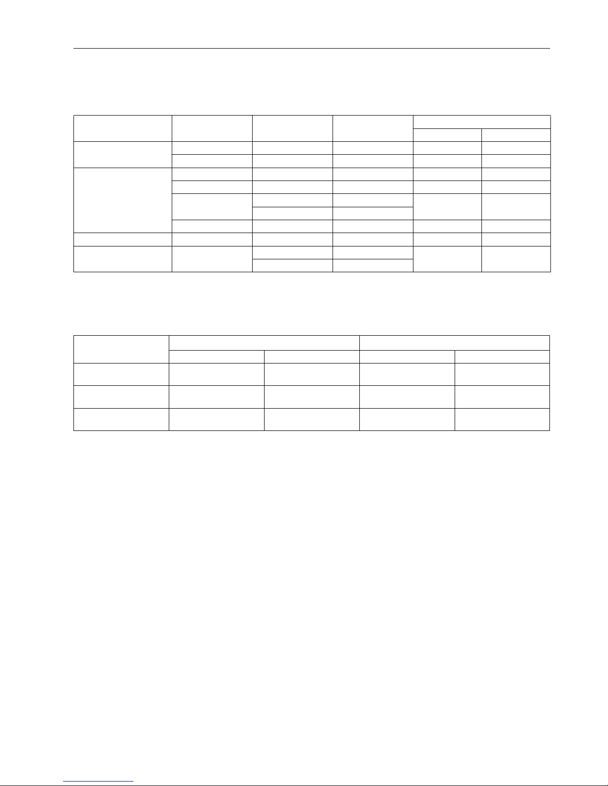
Table 8: Electrical connection for Direct Burner Ignition systems
Supply voltage Coil indication Rectifier circuit
position
Coil connection ( fig. 1 ) Valve indication
24 Vac, 50/60 Hz 24 Vrac External Series connection pin1 and pin 5 or
plug 45.900.441-029
VK 81.5
24 Vac, 50/60 Hz 24 Vrac In plug Select plug 45.900.441- with rectifier
(See table 11)
VK 81.5
100 Vac, 50/60 Hz 100 Vrac External Series connection pin1 and pin 5 VK 41.5
110 Vac, 50/60 Hz 110 Vrac In S4575 Select plug 45.900.441-033
without rectifier (See table 11)
VK 41.5
In plug Select plug 45.900.441-039
(See table 11)
VK 41.5
External Series connection pin1 and pin 5 VK 41.5
220 ... 240 Vac, 50/60 Hz 220 ... 240 Vrac In S4565 Select plug 45.900.441-033
without rectifier (See table 11)
VK 41.5
In plug Select plug 45.900.441- with rectifier
(See table 11)
VK 41.5
External Series connection pin1 and pin 5 VK 41.5
Table 9: Electrical connection for Intermittent Pilot ignition systems
Supply voltage Coil indication Rectifier circuit
position
Coil connection ( fig. 1 ) Valve indication
24 Vac, 50/60 Hz 24 Vrac External Parallel connection pin1/2 and pin 4/5 VK 81.0
220 ... 240 Vac, 50/60 Hz 220 ... 240 Vrac In S4565 and
S4585 types
S4565 and S4585 types VK 41.0
220 ... 240 Vac, 50/60 Hz 220 ... 240 Vrac External Parallel connection pin1/2 and pin 4/5 VK 41.0
Table 10: Power consumption (W) and current (mA)
Supply voltage Power consumption Current
Nominal voltage 110% nominal voltage Nominal voltage 110% nominal voltage
1
st
operator
1
st
+ 2
nd
operator
1
st
operator
1
st
+ 2
nd
operator
1
st
operator
1
st
+ 2
nd
operator
1
st
operator
1
st
+ 2
nd
operator
DBI system
24 Vac, 50/60Hz -- 9.2 -- 11 -- 424 -- 466
100 Vac, 50/60Hz -- 9.75 -- 11.9 -- 105 -- 115
110 Vac, 50/60Hz -- 8.8 -- 10.8 -- 89 -- 98
220 Vac, 50/60Hz -- 9.4 -- 11.4 -- 48 -- 52
240 Vac, 50/60Hz -- 11.2 -- 13.6 -- 52 -- 57
IP system
24 Vac, 50/60Hz 6.7 6.7 + 3.1 8.0 8.0 + 3.7 309 309 + 143 340 157
220 Vac, 50/60Hz 9.1 4.8 11 5.8 46 24 51 27
240 Vac, 50/60Hz 10.9 5.7 13.1 6.9 50 26 55 29
220Vac, 50/60Hz 7 7 + 2.2 8.3 8.3 + 2.7 31 31 + 11 35 35 + 12.2
240 Vac, 50/60Hz 8.0 8.0 + 2.6 9.6 9.6 + 3.2 35 35 + 12.1 38.4 38.4 + 13.3
Page 11
11 EN2R-9004 0606R20-NE
Fig. 1. Coil connection
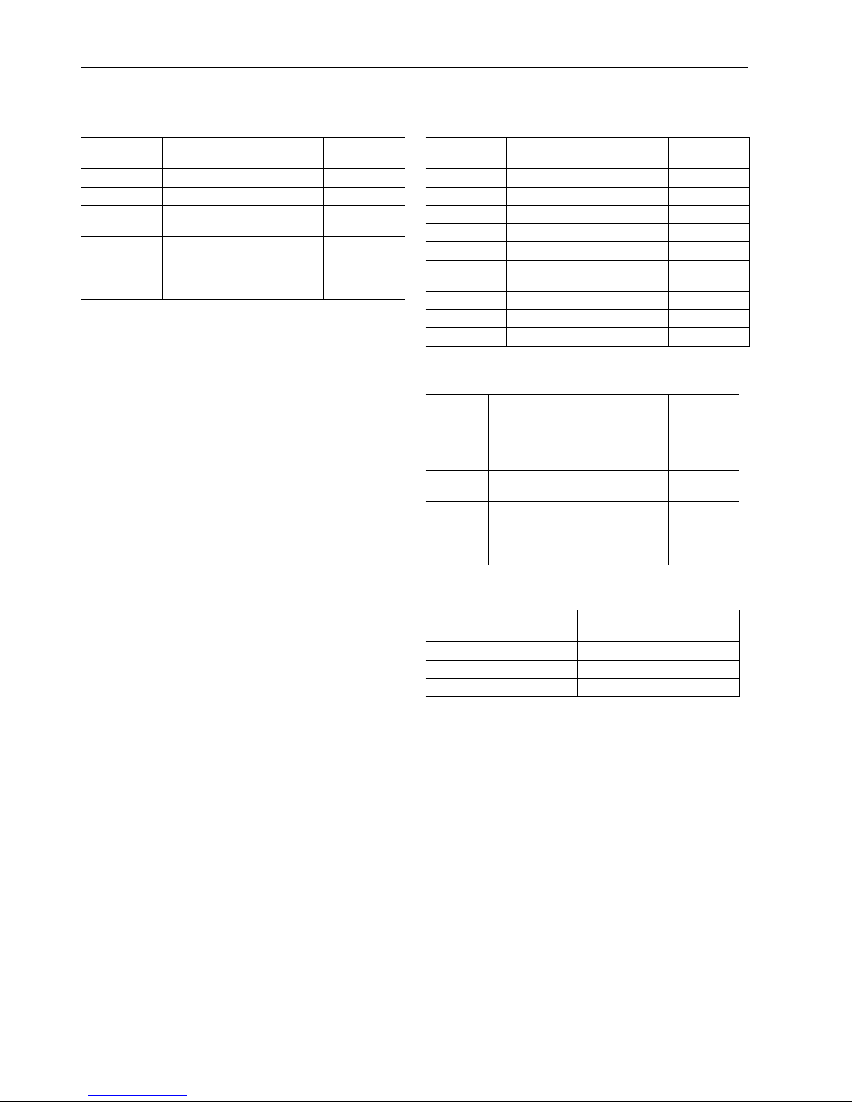
Rectifier plug
The 220/240 V,110V and 24 V versions of the VK4105/
VK8105 series gas controls can be connected to any standard
DBI control with a 220/240 Vac, 110V or 24 Vac output by
using a rectifier plug 45.900.441- See table 11.
Electical protection of gas control with rectifier plug
IP 40
Mounting of rectifier plug
fig. 2 .
Mounting screw
Torque: 40 Ncm max.
Fig. 2. Mounting of rectifier plug
IMPORTANTIMPORTANT
Warranty claims are not accepted if not the specified
plug/rectifier circuit is used.
V1
1Pin number 2 3 4 5
V2
Page 12

EN2R-9004 0606R20-NE 12
Table 11: Rectifier plugs
Order number Supply
voltag e
Wires Cable
length
Plug Cable end
Vac u nle s s
specified
(mm) config Rectifier screw config strip
length
(mm)
Special Finish
45.900.441-011 220/240 3 145 fig. 25 yes in bag fig 20 75 solder dip
45.900.441-012 24 2 500 fig. 25 yes in bag fig 22
45.900.441-013 220/240 3 500 fig. 25 yes in bag fig 20 50 splices
45.900.441-014 220/240 3 620 fig. 25 yes no fig 20 80 solder dip
45.900.441-015 24 2 500 fig. 25 yes in bag fig 20 50 splices
45.900.441-016 220/240 3 240 fig. 25 yes in bag fig 20 150 solder dip
45.900.441-017 220/240 3 150 fig. 25 yes in bag fig 20 40 solder dip
45.900.441-018 220/240 3 800 fig. 25 yes in bag fig 20 75 solder dip
45.900.441-019 24 2 50 fig. 25 yes inserted fig 23
45.900.441-021 24 2 720 fig. 25 yes in bag fig 20 80 solder dip
45.900.441-022 24 2 720 fig. 25 yes inserted fig 21
45.900.441-023 24 2 1260 fig. 25 yes in bag fig 20 80 solder dip
45.900.441-024 24 2 1260 fig. 25 yes inserted fig 21 solder dip
45.900.441-025 220/240 3 600 fig. 25 yes no fig 20 130 solder dip
45.900.441-026 220/240 3 1500 fig. 25 yes in bag fig 20 50 solder dip
45.900.441-027 220/240 3 580 fig. 24 yes inserted fig 21 * * earth wire
= 6.5
faston
fema le
45.900.441-028
(as -027, but single
packed in bag)
220/240 3 580 fig. 24 yes inserted fig 21 * * earth wire
= 6.5
faston
fema le
45.900.441-029 24 Vdc 2 500 fig. 24 no in bag fig 20 50 splices
45.900.441-030 220/240 3 500 fig. 25 yes no fig 20 50 splices
45.900.441-031
(for IP application)
220/240 4 700 fig. 25 double in bag fig 20 50 splices
45.900.441-032 220/240 3 1050 fig. 25 yes no fig 20 150 splices
45.900.441-033 220/240
Vdc
3 500 fig. 25 no inserted fig 20 50 splices
45.900.441-035 220/240 3 403 fig. 25 yes inserted fig 20 special special
earth wire
solder dip
45.900.441-036 220/240 3 570 fig. 25 yes inserted stocko
connectors
45.900.441-037 220/240 3 1800 fig. 25 yes in bag fig 20 50 solder dip
45.900.441-038 220/240 3 397 fig. 25 yes inserted stelvio
connectors
earth wire
stripped
splices
45.900.441-039 110 3 500 mmfig. 25 yes in bag fig 20 50 solder dip
Page 13

13 EN2R-9004 0606R20-NE
CAPACITY CURVE H10 (CVI)
MINIMUM CAPACITY CURVE
0
1
2
3
4
5
6
7
8
9
10
11
12
012345678
FLOW (m³/h) at 1013 mbar and 15˚C, dry
PRESSURE DROP (mbar)
AIR
G110/120
G140
G20
G25
G30
BG1/BG2 VK410./VK810. BP: 50/0 SIZE: 1/2" DATE: 96-06-11 REV: 3 H10
Page 14

EN2R-9004 0606R20-NE 14
CAPACITY CURVE H20 (CVI)
0
1
2
3
4
5
6
7
8
9
10
11
12
13
14
15
16
17
18
19
20
012345678910
/h) at 1013 mbar and 15
PRESSURE DROP (mbar)
AIR
G110/120
G140
G20
G25
G30
BP:
50/10
SIZE:
1/2"
DATE: 14-10-02 REV:
4
S V /MV : 17/17
VK 411 ../VK 811 .. ,V B
MINIMUM CAPACITY CURVE
FLOW (m
3
C, dry
o
Page 15

15 EN2R-9004 0606R20-NE
CAPACITY CURVE H140 (CVI)
MINIMUM CAPACITY CURVE
0
1
2
3
4
5
6
7
8
9
10
11
12
012345678
FLOW (m³/h) at 1013 mbar and 15˚C, dry
PRESSURE DROP (mba
r
AIR
G110/120
G140
G20
G25
G30
BG1/SM2 VK411. / VK811. BP: 50/10 SIZE:1/2" DATE: 96-06-11 REV: 0 H140
Page 16

EN2R-9004 0606R20-NE 16
CAPACITY CURVE H150 (CVI)
MINIMUM CAPACITY CURVE
0
1
2
3
4
5
6
7
8
9
10
11
12
012345678
FLOW (m³/h) at 1013 mbar and 15˚C, dry
PRESSURE DROP (mba
r
AIR
G110/120
G140
G20
G25
G30
BG1/SM2 VK412./VK812. BP: 50/50 SIZE:1/2" DATE: 96-06-11 REV: 0 H150
Page 17

17 EN2R-9004 0606R20-NE
CAPACITY CURVE H160 (CVI)
MINIMUM CAPACITY CURVE
0
1
2
3
4
5
6
7
8
9
10
11
12
012345678
FLOW (m³/h) at 1013 mbar and 15˚C, dry
PRESSURE DROP (mba
r
AIR
G110/120
G140
G20
G25
G30
BG1/BG2/THR VK410.E,T/VK810.E,T BP: 50/0 SIZE: 1/2" DATE: 96-06-11 REV: 0 H160
Page 18

EN2R-9004 0606R20-NE 18
CAPACITY CURVE H170 (CVI)
MINIMUM CAPACITY CURVE
0
1
2
3
4
5
6
7
8
9
10
11
12
012345678
FLOW (m³/h) at 1013 mbar and 15˚C, dry
PRESSURE DROP (mba
r
AIR
G110/120
G140
G20
G25
G30
BG1/BG2/THR VK411.E,T/VK811.E,T BP: 50/10 SIZE:1/2" DATE: 96-06-11 REV: 0 H170
Page 19

19 EN2R-9004 0606R20-NE
PERFORMANCE CHARACTERISTICS
Maximum allowable leakage
Each gas control is factory tested to meet the following
leakage requirements:
• outerwall: 50 cm
3
/h at test pressure of 150 mbar.
• safety valve: 40 cm
3
/h at test pressure of 6 and 150 mbar.
• main valve (plus operator inlet valve): 40 cm
3
/h at test
pressure of 6 and 150 mbar.
Outlet pressure adjustment range capability
Manuf./Natural/LP gas:
1.5 ... 20 mbar
2 ... 37 mbar with block function up to 50 mbar
LP gas: 5 ... 60 mbar.
Minimum adjustable capacity
For versions with a throttle valve (suffix E/T/VE) the minimum
adjustable capacity is 0.6 m3/h air at ∆P of 20 mbar.
Pilot flow
Pilot flow capacity is more than 0.1 m
3
/h at 9 mbar
pressure drop.
Recovery time of servo system
The recovery time of the adjustable
SOFTLITE system in
minimum position is within 15 seconds from operator
de-energization and in maximum position the recovery time
shall be within 30 seconds from operator de-energization.
High pressure test
In the ”OFF” condition, the gas control will withstand 3 bar (air)
inlet pressure without damage. Attempts to operate the gas
control, while in this fault condition will not damage it.
Operable voltage range
The gas control will function satisfactory between 85% and
110% of the rated voltage.
.
Valve closing characteristics
The gas control will close within 1 second from operator deenergization, (at an inlet pressure of 22.5 mbar and minimal
2.5 mbar pressure drop).
Main valve opening characteristics (measured with gas)
Fast opening versions
Under conditions where the supply pressure is at least 2.5
mbar above the outlet pressure setting, the dead time shall be
0.5 s maximum.
The outlet pressure will reach 80% of the rated flow within 1
second from start of flow.
Full outlet pressure will be reached within 5 seconds.
SOFTLITE versions (See table 13)
The adjusted outlet pressure will be reached between 5 and
15 seconds from start of flow (for LP gas between 4 and 10
seconds)
Adjustable
SOFTLITE
NOTE: For
SOFTLITE versions the SO FTLITE pressure can be
adjusted from the rated SOFTLITE up to the desired
value.
Table 12: Operable voltage range
Rated voltage Operable voltage
24 Vac, 50/60 Hz 19.5 ... 27 Vac
100 Vac, 50/60 Hz 85 ... 110 Vac
220/240 Vac, 50/60 Hz 187 ... 264 Vac
Table 13: Main valve (class D only) opening characteristics sOFTLITE versions
SOFTLITE
number
Inlet
pressure
(mbar)
Kind of gas Dead time (s) max Out let pressure (mbar)
1.5 s after start of flow
(in min. position)
Outlet pressure (mbar)
1.5 s after start of flow
(in max. position)
Upright
positon
Horizontal
position
3 20 G 20/25 1.8 1.5 1 ... 3.5 > 12
5
7
20 G 20/25 1.2 1.0 2.5 ... 6.0
4.5 ... 7.5
> 12
7 37 G 30/31 1.5 1.2 2.5 ... 6.5 > 16
7 50 G 30/31 1.2 1.0 2.5 ... 6.5 > 19
Page 20

EN2R-9004 0606R20-NE 20
Oscillation
Maximum oscillation under all circumstances:
±
0.5 mbar.
Tap sensitivity of outlet pressure set point
For all gases the maximum deviation may be 1 mbar.
Repeatability of outlet pressure set point
For all gases the maximum deviation from set point is:
±
0.3
mbar or
±
3% of the set point value, whichever is the greatest.
Design life
500.000 cycles for safety and main valve operator.
Cycle frequency maximum 100 cycles /hour.
Total set point shift
*
)
For other versions see the applicable handbook
Temperature sensitivity VK41../81..VE type:
-15 ... 70°C : 4% of flow
Table 14: Total set point shift servo regulator on/off
version*
)
Pressure range Tolerance
1.5 ... 20
2 ... 37
6% of the set point value or 1 mbar
whichever is the greatest
5 ... 50 6% of the set point value or 1.5 mbar
whichever is the greatest
Page 21

21 EN2R-9004 0606R20-NE
INSTALLATION
IMPORTANTIMPORTANT
Take care that installer is a trained experienced
service man.
Turn off gas supply before starting installation.
Disconnect power supply to prevent electrical shock
and/or equipment damage.
Do not remove seals over inlet and outlet until the
device is ready to be installed.
Take care that dirt cannot enter the gas control during
handling.
Mounting position
The gas control can be mounted 0 to 90 degrees in any
direction from the upright position (from the position when the
operators are on top).
Main gas connection
Gas controls with internal thread
• Take care that dirt cannot enter the gas control during
handling.
• Use a sound taper fitting with thread according to ISO 7-1
or a piece of new, properly reamed pipe, free from swarf.
• Do not thread or tighten the pipe or pipe fitting too far (see
table below). Otherwise distortion and malfunction could
result.
• Apply a moderate amount of good quality thread compound
to the pipe or fitting only, leaving the two end threads bare.
PTFE tape may be used as an alternative.
• Tighten gas control using the right open end wrench. fig. 3
.
Fig. 3.
• Ensure the gas flows in the same direction as the arrow on
the bottom of the gas control.
Gas controls for flange connection
• Insert ”O”-ring in the groove of each flange. If necessary
grease ”O”-ring slightly to keep it in place.
• Mount gas control between flanges using the four screws
for each flange.
Gas controls with external thread connection
IMPORTANTIMPORTANT
Fastening torque flat sealing ring only applicable for
type Klingersil C4324
Olives for this application are not supplied by Honeywell
Torque of olive applications may differ depending on
olive dimensions.
With 1/2” nut and flat sealing ring for pipe 14 mm ( fig. 4 .)
Nut: drawing:........................................ 45.006.583-005
Flat sealing ring according to DIN 3535-6 with size
∅18 x ∅12 x 1.5 mm
drawing................................................. 45.006.582-002
Fastening torque: maximum 40 Nm
minimum 25 Nm
Pipe end construction: see fig.: 7.
With 1/2” nut and flat sealing ring for pipe 15 mm ( fig. 4 .)
Nut: drawing:........................................ 45.006.583-004
Flat sealing ring according to DIN 3535-6 with size
∅18 x ∅12 x 1.5 mm
drawing................................................. 45.006.582-002
Fastening torque: maximum 40 Nm
minimum 25 Nm
Pipe end construction: fig. 8 .
Fig. 4. External thread connection with nut and flat
sealing ring
Pipe size (inch) Max. length of pipe thread (mm)
3
/
8
14
1
/
2
18.6
Page 22

EN2R-9004 0606R20-NE 22
With 3/4” nut and olive ( fig. 5 .)
Pipe diameter: 15 mm
Nut: drawing:........................................ 45.006.583-003
Fastening torque: maximum 50 Nm
minimum 30 Nm
Pipe end construction: square off end of tubing and
remove burrs.
Fig. 5. External thread connection with nut and olive
With 3/4” nut and “O”-ring ( fig. 6 .)
Pipe diameter: 15 mm
Nut: drawing:........................................ 45.006.583-003
“O”-ring size: ∅14.3 x ∅2.4 mm
drawing ................................................ 45.001.583-003
Fastening torque: maximum 50 Nm
minimum 10 Nm
Pipe end construction: fig. 9 .
Fig. 6. External thread connection with nut and “O”-ring
With 3/4” nut and flat sealing ring for pipe 15 mm ( fig. 4 .)
Nut: drawing:........................................ 45.006.583-003
Flat sealing ring according to DIN 3535-6 with size
∅24 x ∅16 x 1.5 mm:
drawing ................................................ 45.006.582-001
Fastening torque: maximum 50 Nm
minimum 30 Nm
Pipe end construction: fig. 10 .
With 3/4” nut and flat sealing ring for pipe 18 mm ( fig. 4 .)
Nut: drawing:........................................45.006.583-002
Flat sealing ring according to DIN 3535-6 with size
∅24 x ∅16 x 1.5 mm
drawing.................................................45.006.582-001
Fastening torque: maximum 50 Nm
minimum 30 Nm
Pipe end construction: fig. 11 .
Fig. 7. Pipe (dia 14 mm) for flat sealing ring connection
Fig. 8. Pipe (dia 15 mm) for flat sealing ring connection
Fig. 9. Pipe end for “O”-ring connection
Fig. 10. Pipe (dia 15 mm) for flat sealing ring connection
Fig. 11. Pipe (dia 18 mm) for flat sealing ring connection
Pressure feedback connection
WARNING
To avoid decreasing of performance of pressure
regulator by pinching off the pressure feedback tubing,
it is recommended to use a tube material which will not
kink.
1
14 18
+ 0.2
- 0.2
1
15 18
+ 0.2
- 0.2
1
15
23.4 +/- 0.15
15
7.5 +/- 0.2
+ 0.10
- 0.05
1
15 23.4
+ 0.2
- 0.2
1
18 23.4
+ 0.2
- 0.2
Page 23

23 EN2R-9004 0606R20-NE
Pilot gas connection (if applicable)
• Square off the end of tubing and remove burrs.
• Slip compression fitting over tubing.
• Insert tubing into gas control housing until it bottoms, slide
fitting into place and turn finger tight.
• Use a wrench to tighten fitting about 1
1
/2 turn beyond finger
tight to shear of the olive. Do not use jointing compound.
Connect other end of tubing to pilot burner according to the
manufacturer’s instructions.
CAUTION
Do not bend tubing at gas control after compression
fitting has been tightened, as this may result in gas
leakage at the connection.
Perform gas leak test
WARNING
FIRE OR EXPLOSION HAZARD CAN CAUSE
PROPERTY DAMAGE, SEVERE INJURY OR DEATH
Check for gas leaks with a rich soap and water solution
any time work is done on a gas control.
Gas leak test
• Paint all pipe connections upstream of the gas control with
a rich soap and water solution. Bubbles indicate a gas leak.
• If a gas leak is detected, tighten the pipe connection.
• Stand clear while lighting the main burner to prevent injury
caused from hidden gas leaks, which could cause flasback
in the appliance vestibule. Light the main burner.
• With the main burner in operation, paint all pipe joints
(including adapters) and gas control inlet and outlet with
with a rich soap and water solution an approved leak
detection fluid.
• If another gas leak is detected, tighten adapter screws,
joints and pipe connections.
• Replace the part if gas leak can not be stopped.
CAUTION
Keep soap and water solution away from electrical
connecetions.
Page 24

EN2R-9004 0606R20-NE 24
ELECTRICAL CONNECTIONS AND WIRING
IMPORTANTIMPORTANT
Wiring must be in accordance with local regulations.
The appliance manufacturer’s instructions should
always be followed.
Before installing or replacing any control check that
type number is correct for the application.
Ensure combustion chamber is free of gas before
start up.
Conduct a thorough check out when installation is
completed.
At the first start the ignition control can be in lock out;
depress reset button to free control.
WARNING
Take care that installer is a trained experienced service
man. Turn off gas supply before starting installation.
Disconnect power supply to prevent electrical shock
and/or equipment damage.
IMPORTANTIMPORTANT
Warranty claims are not accepted if the specified
plug/rectifier circuit is not used.
Wiring
• Use cable which can withstand 105°C ambient.
• Use cable which is proven against moisture.
• Wiring between ignition control and spark sensing probe
should have good quality insulation, suitable for the temperatures encountered.
Assembling of the cable connector(s) for IP 20 protection
Follow the sequence as mentioned under Assembling of the
cable connector(s) for IP 44 protection" except the assembling
of the grommet.
Assembling of the cable connector(s) for IP 44 protection ( fig. 12 .)
• Use cable with Ø 5 ... Ø 7 mm.
• Strip length cable: 15 mm
• Grommet inlet numbers1, 2, 4 applicable for cable
with Ø 5 ... Ø 7 mm.
• Grommet inlet number 3 applicable for cable
with Ø 4 ... Ø 7 mm.
• Mount the connector(s) and bring the cable grommet in
position over the cables and connector.
Fig. 12.
Assembly of cover with integrated strain relief ( fig. 13 .)
Position the cover on the ignition control. Then, when holding
the cover down (in direction A) rotate it to mount the cable(s) in
the strain relief (in direction B).
Finally fix the whole assembly (ignition control and cover) with
a screw on the gas control with a torque of 40 Ncm max.
Fig. 13.
Disassembly of cover with integrated strain relief
• Loosen the cover screw.
• Pull up the cover screw by hand, lift the cover slightly and
push it in the direction of the cables.
Fusing
In order to prevent unsafe conditions at too high current, the
ignition controls S4565, S4575 and S4585 series have an
integral non replaceable fuse.
This fuse will be blown long before the maximum 16 A external
fuse switches off.
Spark gap
Max. allowable spark gap 3.5 mm
Supply voltage polarity
WARNING
If ignition control seems to operate normally but does
not detect flame, check for right polarity of power supply
(line, neutral).
Checking flame current
• The minimum value should be in accordance with specified
value.
• To check flame current connect a DC micro-Ampèremeter
between flame sensing wire and flame sensing rod.
• If flame current is insufficient check that flame sensing rod
is fully enveloped by the flame and that burner is reliable
grounded to ignition control.
• If there is no sufficient flame current due to phase-phase
mains it is recommanded to use a AT7030A or AT7030B
flame detection transformer. See also instruction sheet
EN1R-9136 for AT7030 transformer.
WARNING
Short µA meter during ignition, to prevent damage of
the µA meter in single rod application.
Grommet
Connector
1
3
2
4
A
B
Page 25

25 EN2R-9004 0606R20-NE
ADJUSTMENTS AND CHECKOUT
IMPORTANTIMPORTANT
Adjustments must be made by qualified persons only.
If the appliance manufacturer supplies checkout and/
or service and maintenance instructions carefully follow them. If these instructions are not provided then
use the procedure outlined below.
Pressure tap
The gas control is provided with a pressure tap of 9 mm outer
diameter at inlet and outlet side.
When checking the pressure undo the screw a half turn and
slip tube over nipple.
Ensure that screw is retightened after making test.
Pilot flame (VK4100/VK8100 only)
WARNING
It should be noted, that after a long time of stoppage
(summer) it can take up to 60 s to come to an ignition of
the pilot burner.
Outlet pressure adjustment on/off versions (see page 4 )
• Disconnect pressure feedback connection (if applicable)
• Start-up appliance in order to have gas input to burner.
• Check gas input to the appliance using a clocking gas
meter or alternatively a pressure gauge connected to the
outlet pressure tap.
• Remove cap screw to expose pressure regulator
adjustment screw.
• Slowly turn adjustment screw with a small screw driver until
the burner pressure required is recorded on the pressure
gauge. Turn adjustment screw clockwise to increase or
counter-clockwise to decrease gas pressure to the burner.
• For non-regulating mode (LP gas) turn adjustment screw
clockwise until it stops.
• Replace pressure regulator cap screw.
• Connect pressure feedback connection (if applicable).
Outlet pressure adjustment throttle versions VK.1..E/T(see page 4)
• Energize electric operators in order to have gas input to
burner.
• Check input to the appliance using a clocking gas meter or
alternatively a pressure gauge connected to the oultet
pressure tap.
• Turn the flow adjustment screw with a screw driver in
clockwise direction to decrease and turn counter
clockwise to increase the gas flow.
Check of
SOFTLITE
The SOFTLITE pressure is factory set.
Check burner performance at this pressure observing burner
ignition and flame characteristics. Burner should ignite
promptly and without flash back to orifice and all ports should
remain lit.
Cycle burner several times (wait 15 seconds between cycles
to allow servo system to resume slow open action).
Repeat check of slow opening after allowing the appliance to
cool down.
SOFTLITE adjustment (see page 4)
The
SOFTLITE pressure can be increased from the rated
SOFTLITE to optimise the ignition or to change over to another
gas type.
• Check the ignition as described above.
• Turn the appliance off.
• Remove the dust cap. This can be done by turning it 45
degrees counter-clockwise and then lifting off the dust cap
• Turn the adjustment screw one step in the direction ”MAX”
to increase or in the direction ”MIN” to decrease the
SOFTLITE pressure.
NOTE: Change over from natural gas to LP gas by turning
from mininimum to maximum.
• Start up the appliance and re check the ignition, and repeat
the adjustment if needed.
• Replace dust cap.
Throttle adjustment ..VE types.
The position of the throttle screw can be found on page 5.
Apply a screwdriver to turn the screw.
To decrease the flow, turn screw clockwise.
To increase flow, turn screw counter-clockwise.
WARNING
Applied torque may not exceed 8 Ncm
Final checkout of the installation
Set appliance in operation after any adjustment and observe
several complete cycles to ensure that all burner components
function correctly and that cap screw and cover are fitted and
secured.
Maintenance and service
Under normal circumstances no maintenance or service is
required.
Screws on the gas control that have been sealed must never
be removed.
Throttle scre
w
decrease flow
(pressure)
increase flow
(pressure)
Page 26

EN2R-9004 0606R20-NE 26
CONSTRUCTION AND WORKING PRINCIPLES
Servo pressure regulation
The VK4100/VK8100 series gas controls features the positive
servo system, i.e. the main gas valve is closed by spring
pressure in the normal shut down position and can only be
opened when gas pressure is sufficient to overcome the
spring force. This valuable built in safety feature ensures the
main valve wil automatically close in the event of power or gas
supply failure.
The heart of the system is the servo pressure regulator which
consists of a pressure relief valve integrated in a regulator
diaphragm which is fitted above and controls the main valve.
When the direct on/off operator and servo on/off operator are
energized, inlet gas flows through the servo orifice and
through the open operator valve into the servo system and the
regulator. This servo gas moves the main valve diaphragm
upwards enough to open the main valve. As soon as the main
valve has opened, the outlet pressure will be sensed by the
regulator diaphragm via the feedback channel.
When the force operated by the pressure is greater than that
preset by the adjustment screw, the regulator valve opens
relieving some of the working pressure. This reduces the force
against the main valve spring allowing the main valve to close
proportionately. Thus the main valve limits the outlet (or
burner) pressure to the preset level.
As a result, outlet pressure is continuously maintained by
comparing it to the preset pressure and adjusting the position
of the main valve accordingly. This means that a constant
outlet pressure is maintained regardless of inlet pressure
variations.
At shut down, the small volume of working gas in the regulator
and the diaphragm chamber is dumped into the main outlet
chamber.
A reference pressure feedback connection further regulates
the outlet pressure by compensating for differences in the air
pressure in the combustion chamber and at the valve.
If pressure regulation is not needed, the regulator spring can
be blocked by turning the adjustment screw down until it stops
or the pressure regulation is removed. In these cases the full
servo gas pressure opens the main valve as far as the
pressure drop allows.
Fig. 14. Servo pressure regulation working
Page 27

27 EN2R-9004 0606R20-NE
SOFTLITE
Some burners function well using a fast opening valve with the
pressure build up as shown in fig. 15. However, other burner/
appliance combinations need a means of improving their
ignition characteristics by providing quieter ignition and
reducing flame roll-out. The
SOFTLITE mechanism achieves
this by changing the profile of the outlet pressure curve as
shown in fig. 15.
An extra diaphragm and spring are inserted below the main
diaphragm. When the electric servo operator valve is opened,
working gas enters the
SOFTLITE chamber via the inlet orifice,
and is fed into the space between the diaphragms. Working
gas pressure rapidly increases to a preset level, partially
opening the main valve ( fig. 16 .).
As soon as it reaches the start level it overcomes the
SOFTLITE
spring pressure. The resultant move of the
SOFTLITE
diaphragm inhibits the increase of working gas pressure on
the main valve diaphragm. Only when the
SOFTLITE spring has
been totally compressed does the working gas pressure
increase rapidly once again until the regulator set point
pressure is reached.
Fig. 15. Opening characteristics
SOFTLITE adjustment
The adjustable
SOFTLITE feature allows for individual SOFTLITE
setting from the rated min. setting upwards and for switching
over from natural gas to LP gas pressures.
An example is given in fig. 18.
Fig. 16. Servo pressure regulation
SOFTLITE models
SOFTLITE
Fast open
time (s)
02
SOFTLITE ON position,
SOFTLITE gas only, main valve partially open
SOFTLITE ON position, main valve open
Safety valve open
Page 28

EN2R-9004 0606R20-NE 28
Fig. 17. Safety valve and main valve open position
Fig. 18. Adjustable
SOFTLITE
MAX
MIN
A
B
E
D
C
A
B
E
D
C
0
0
10
20
30
5
MAX
AA
BB
CC
DD
EE
MIN
10 15
Time (seconds)
Outlet pressure (mbar)
Example:
SOFTLITE curve VK41../VK81..
SOFTLITE spring: 5 mbar
Gas family: LP Gas (G30, G31
Inlet pressure: 37 mbar
Adjustable
SOFTLITE setting positioning
Page 29

29 EN2R-9004 0606R20-NE
QUALITY ASSURANCE STATEMENT
Products are manufactured under an ISO 9001 (1994) based
and certified Quality System.
The quality system is described in the Honeywell Combustion
Controls Center Quality Assurance Programme and its related
operational procedures and instructions.
The quality system is approved by Gastec against certificate
number 9.302/2.
The quality organisation is responsible for defining,
maintaining, improving and verification of the quality systems
in the field of design, production process and field quality
service.
Assembly processes are guided by work instructions. Patrol
inspections form part of the assembly processes.
At the end of the assembly phase, all gas controls are leakage
and performance tested/adjusted.
Assembly inspection is performed by employees of the quality
control department, using their own authorised equipment.
All inspections (incoming and assembly) are performed by
trained personel and according inspection procedures.
Page 30

EN2R-9004 0606R20-NE 30
STANDARDS AND APPROVALS
Standards
The gas control has been designed to meet the European
Standards:
EN 88: Pressure govenors
EN 126: Multifunctional controls.
EN 161: Automatic shut off valves
The safety shut off valve meets class A or B requirements
depending on model number.
The servo operated main valve meets class J requirements in
case of: VK4100/VK4105
The servo operated main valve meets class C requirements
in case of VK4110/VK4115
The servo operated main valve meets class B requirements
in case of VK4120/VK4125
A class J valve as mentioned in EN 161; 1997 is equal or
better than a class D’ valve as mentioned in EN 297 and EN
483 and class D valves as mentined in other standards.
According to bending stresses the gas control meets the
highest requirements (group 2).
The pressure govenor meets class B performance.
Regarding electric safety, the gas control can be used in
appliances according to European Standard for household
electrical requirements EN 60335 series.
The gas control also meets all Electro Magnetic Compatability
standards for non-industrial appliances.
Approvals
The gas control conforms with the following EC - Directives:
• Gas Appliance Directive (90/396/EEC)
• Low Voltage Directive (73/23/EEC)
• Electro Magnetic Compatability Directive (89/336/EEC)
The fact that the gas control is certified to european standard
EN 88 EN 126 and EN161 means that the gas control meets
the requirements in all EC and EFTA countries.
Details per O.S. number can be found in the Approvals List.
Page 31

31 EN2R-9004 0606R20-NE
ORDERING INFORMATION
When ordering specify:
• Model number of CVI gas control component required: see
model number chart below.
• The correct pilot burner for the installation concerned: refer
to Honeywell ignition products guide EN0R-0038.
NOTE: Complete gas control, replacement parts and
accessories will be available under ”TRADELINE”
label. Ask your wholesaler for details.
Fig. 19. Model number chart VK series gas controls
VK
410
A 9999
Ordering Specification number
0
A: fast opening with regulator
B: fast opening without regulator
C: SOFTLITE opening with regulator
D: SOFTLITE opening without regulator
E: fast opening with throttle
F: Integrated gas/air 1:1 with venturi mixing
system
M: fast opening with Modureg
N: SOFTLITE opening with Modureg
P: fast opening with High-Low
Q: SOFTLITE opening with High-Low
R: fast opening with regulator and suitable
for gas/air application
T: SOFTLITE opening with throttle
V: Integrated gas/air 1 : 1
VE: Integrated gas/air 1 : 1 and throttle
Valve classification
0: Class B + J
1: Class B + C
2: Class B + B
1: CVI system valve
4: line voltage
8: low voltage
VK: product family identifier
0: pilot outlet, IP ignition system
5: no pilot outlet, DBI ignition system
Specification number
Page 32

EN2R-9004 0606R20-NE 32
REPLACEMENT PARTS AND ACCESSORIES
Contents
Replacement parts and accessories page
Flange assemblies.......................................................... 32
Fitting ............................................................................ 32
Gas pressure switch ..................................................... 33
Miscellaneous ............................................................... 33
Plugs .............................................................................. 33
FLANGE ASSEMBLIES
1)
Not applicable for mounting over pilot outlet.
2)
Applicable for mounting in all directions.
* Provided with
1
/8” BSP. Tr pressure tap hole
FITTING
1)
Only applicable for VK41../VK81..R
Connection size Configuration ”O”-ring and
screws
Packing quantity
(pcs)
Order number
Straight Elbow
3
/8” BSP.Pl X - YES 200 45.900.400-101
3
/8” BSP.Pl
1)
- X YES 200 45.900.400-103
3
/8” BSP.Pl
1)
- X Only “O”-ring 200 45.900.400-129
1
/2” BSP.Pl X - YES 200 45.900.400-102
1
/2” BSP.Pl X - NO 200 45.900.400-106
1
/2” BSP.Pl X - Only “O”-ring 200 45.900.400-131
1
/2” BSP.Pl X - YES 10 45.002.776-041
1
/2” BSP.Pl
1)
- X YES 200 45.900.400-104
1
/2” BSP.Pl
1)
-X* NO 200 45.900.400-108
1
/2” BSP.Pl
1)
-X* Only “O”-ring 200 45.900.400-130
1
/2” BSP.Pl
1)
X - YES 10 45.002.776-042
1
/2” NPT X - YES 200 45.900.400-122
3
/4” NPT
1)
- X YES 200 45.900.400-146
Ø 18.4 mm X - YES 200 45.900.400-123
Description Material Packing quantity Ordernumber
Compression fitting M8 x 1 for 4 mm pilot tube connection Brass 200 45.900.402-019
Compression fitting M10 x 1 for 6 mm pilot tube connection
1)
Brass 200 45.900.402-020
Compression fitting M11 x 1 for 6 mm pilot tube connection
1)
Brass 200 45.900.402-002
Pressure feedback fitting for 4 mm tube Brass 200 45 .900.402-010
Pressure feedback fitting for 6 mm tube Brass 200 45 .900.402-011
Pressure feedback fitting for 4 mm tube Polyamide 6.6 100 45.900.402-031
Pressure feedback fitting for 6 mm tube Polyamide 6.6 100 45.900.402-034
Page 33

33 EN2R-9004 0606R20-NE
GAS PRESSURE SWITCH
1)
With cover mounted
MISCELLANEOUS
PLUGS
Cable wiring DBI applications
220/240 Volt applications: 3 x 0.75 mm
2
110 Volt applications: : 3 x 0.75 mm
2
24 Volt applications: 2 x 0.50 mm
2
Cable wiring IP applications
220/240 Volt applications: 4 x 0.75 mm
2
For details for specific plug codes, see table 11, page 12
Fig. 20.
Fig. 21.
Fig. 22.
Fig. 23.
Description Packing quantity Ordernumber
Switch point ON: 15.5
±
1; switch point OFF: 13 ± 1, gold plated contacts, red sealing 48 45.900.438-107
Switch point ON: 15.5
±
1; switch point OFF: 13 ± 1, AgNi contacts, blue sealing 48 45.900. 438-109
Switch point ON: 12.5
±
1; switch point OFF: 10 ± 1, AgNi contacts, green sealing 48 45.900.438-110
Switch point ON: 15.5
±
1; switch point OFF: 13 ± 1, AgNi contacts, blue sealing 48 45.900.438-209
1)
Description Packing
quantity
Ordernumber
Cap throtlle valve 1000 45.900.431-008
Gasket for mounting between the gas control and ignition control 2000 45.900.442-007
Gasket for mounting between the gas control and ignition control 192 45.900.442-011
Screw for plug rectifier (45.900.441-xxx) 8000 45.900.445-007
Plug for connecting on coil of the gas control 500 45.900.445-009
6
Cable length
Strip length
80 cable lenght
3 pin rast 5 connector
Lunberg nr. 362303K10
Brown wire connected to st 4-1
Blue wire connected to st 4-2
30
Brown
Blue
Hsg Molex 5557-4r with 2 terminals Molex 5556
Cable length
50
50
AMP F fastin faston 6.35 series
order nr.: 160691-2
Tab housing part nr.: 180916-0
Page 34

EN2R-9004 0606R20-NE 34
Manufactered for and on behalf of the Environmental and Combustion Controls Division of Honeywell Sàrl, Ecublens, Route du Bois 37, Switzerland by its Autorized Representative:
Automation and Control Solutions
Combustion Controls Europe
Honeywell BV
Phileas Foggstraat 7
7821 AJ Emmen
The Netherlands
Tel.: +31 (-)591 695911
Fax: +31 (-) 591 695200
http://europe.hbc.honey well.com
Fig. 24.
Fig. 25.
31
47.8
27.5
34.5
9.3
35
15
35
11.7
7.8
12.5
39
15.5
20.124.8
45.7
30.5
10.2
30.5
 Loading...