

Page 1

V
V
IIII
S
S
TTTT
A
A
----
IIII
C
C
M
M
VV
V
V
VV
Internet Connection Module
Installation and Setup Guide
IIII
SS
S
S
SS
TTTT
AA
A
A
AA
----
IIII
CC
C
C
CC
MM
M
M
MM
K14543V2 2/09 Rev A.
Page 2

Page 3

VISTA-ICM Installation and Setup Guide
Table of Contents
Introduction ............................................................................................................................................... 1
Network Setup and Configuration...........................................................................................................2
Setting up the Network Hardware...........................................................................................................2
Network Setup Requirements.............................................................................................................. 2
Installing a Router or Wireless Access Point ...................................................................................... 3
Installing an Ethernet Hub or Switch .................................................................................................. 3
Connecting a Computer....................................................................................................................... 4
Installing the VISTA-ICM ...................................................................................................................... 4
Installing VISTA-ICM Hardware .......................................................................................................4
Configuring the VISTA-ICM.................................................................................................................. 5
Connecting to the VISTA-ICM setup web pages................................................................................ 5
VISTA-ICM LEDs.............................................................................................................................. 5
VISTA-ICM Setup and Configuration.................................................................................................... 6
Basic VISTA-ICM Setup ........................................................................................................................ 6
Select Devices ..................................................................................................................................... 7
Configure Devices............................................................................................................................... 9
Contact Information .......................................................................................................................... 13
Save Settings ..................................................................................................................................... 14
Advanced Setup .................................................................................................................................... 15
Diagnostics ........................................................................................................................................ 16
File System........................................................................................................................................ 18
Network Settings ............................................................................................................................... 20
Upgrade ............................................................................................................................................. 23
What’s New....................................................................................................................................... 24
Troubleshooting....................................................................................................................................... 25
Network Problems................................................................................................................................. 25
Device Problems ...................................................................................................................................26
i
Page 4

VISTA-ICM Installation and Setup Guide
ii
Page 5

Introduction
Congratulations on your purchase of a Honeywell Internet Connection Module (VISTAICM). The VISTA-ICM is the heart of a state of the art control system that uses
Internet Protocol (IP) and standard Ethernet hardware to integrate control of consumer
electronic equipment with computer networking.
This guide explains the setup and installation process for a Vista VISTA-ICM, but the
general process applies to any VISTA-ICM, and any network device based on In2
Networks Connect and Control technology.
This guide assumes that the installer is familiar with IP networking concepts. See the
In2 Networking Primer for a review of IP networking concepts and terminology.
There are three steps required to setup a home control network (assuming nothing is
already installed).
1. Set up the network.
2. Install the VISTA-ICMs.
3. Configure the VISTA-ICMs.
NOTE: A hardware device connected to an Ethernet network is called a node. Node is
a general term for a VISTA-ICM, and sometimes a VISTA-ICM will be referred to as a
node.
NOTE: The only way to access the VISTA-ICM from outside of your home network is
by the use of a secure VPN software, or equivalent; you cannot gain access by just
typing in the "Honeywell" URL.
VISTA-ICM Installation and Setup Guide
1
Page 6
VISTA-ICM Installation and Setup Guide
Network Setup and Configuration
Setting up the Network Hardware
Network Setup Requirements
Before you begin connecting VISTA-ICMs to the network, you need at least the
following:
• PC or other device capable of browsing the setup web pages
CAUTION: Only Internet Explorer, revision 5.0 or 6.0, is supported. Use of other
browsers will give unpredictable results such as incorrect placement of objects or wrong
colors.
• Router, or wireless router (when using a wireless PDA, wireless tablet or wireless
notebook/laptop)
• VISTA-ICMs and devices to be controlled by the VISTA-ICMs
• Ethernet hub or switch (if you have more than four network devices).
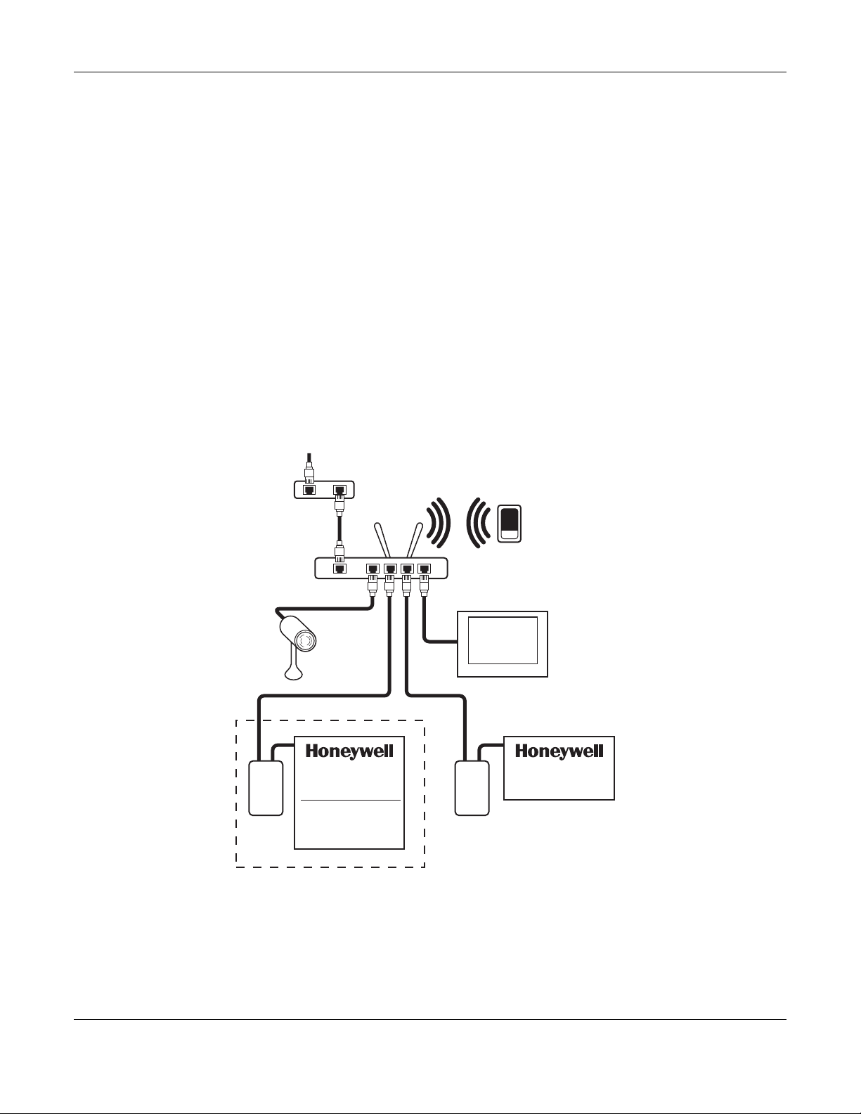
The following illustration shows a network setup with a Honeywell Security system, a
Honeywell thermostat, a network router, an IP camera and a computer.
INTERNET
Broadcast Modem (Optional)
(DSL, Wireless, Cable)
Wireless
Router
WAN LAN
IP Camera
HVAC*
6100 ICM
*REQUIRES
ADDITIONAL
HARDWARE
PC or Tablet
Computer
(Optional)
Figure 1 - Basic Network
PDA or
Web Tablet
(Optional)
SECURITY
VISTA - ICM
VISTA-ICM-002-V0
2
Page 7
VISTA-ICM Installation and Setup Guide
Installing a Router or Wireless Access Point
A router is the easiest and least expensive way to setup a home network. If the home
has a network or an Internet connection, it probably already has a router.
NOTE: If a router is already installed in the home and you are connecting the VISTAICM to the home network, skip this procedure and continue on to connecting a computer.
The router must be installed and configured according to the installation instructions
supplied by the router manufacturer.
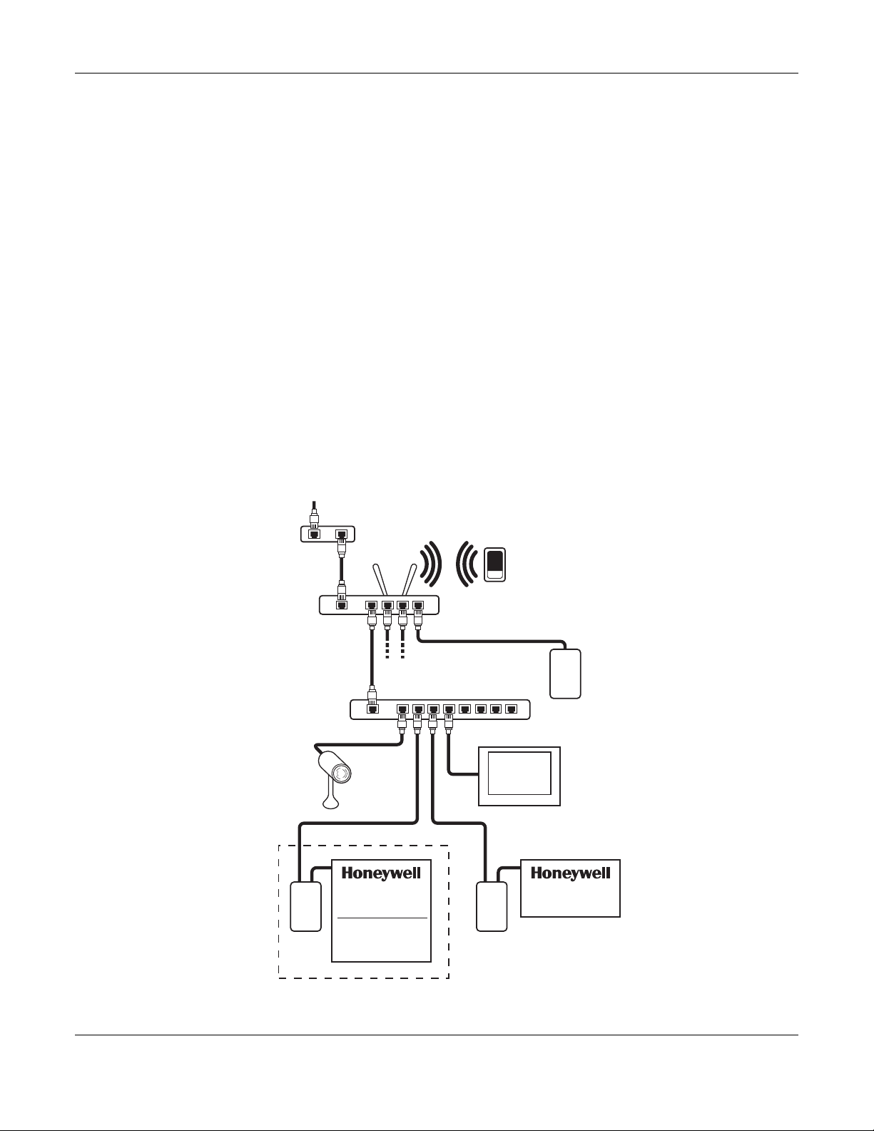
Installing an Ethernet Hub or Switch
Connect an Ethernet hub or switch when there are more network devices than ports on
the router. Connect the uplink port on the hub or switch to one of the Ethernet ports on
the router.
The following general restrictions exist for all Ethernet hubs and switches:
• Each Ethernet device must be home-run from the device to the hub.
• Ethernet cables must be at least Category 5 cable (CAT5). CAT5e is preferred since
a single CAT5e cable can support gigabit Ethernet.
• Ethernet does not support daisy chaining, however, it is possible to add another hub
or switch in a remote location. No more than four hubs can be between any two
Ethernet devices on a Local Area Network.
INTERNET
Broadcast Modem (Optional)
(DSL, Wireless, Cable)
Wireless
Router
PDA or
Web Tablet
(Optional)
WAN LAN
Ethernet Switch (or Hub)
UP Link
IP Camera
HVAC*
6100 ICM
*REQUIRES
ADDITIONAL
HARDWARE
PC or Tablet
Computer
(Optional)
SECURITY
VISTA - ICM
VISTA-ICM-001-V0
Figure 2 - Adding a switch for more Ethernet ports
3
Page 8
VISTA-ICM Installation and Setup Guide
Connecting a Computer
Verify the network installation by connecting a computer to the network. Plug the
computer to one of the Ethernet ports on the router, or a hub or switch that is connected
to the router. Verify that the computer can obtain an IP address and access the router.
Refer to the networking instructions provided by the computer manufacturer to connect
the computer to the network. Each operating system will have a different sequence of
steps to configure the network. The following general tasks must be performed
regardless of the computer or operating system vendor:
1. Connect the Ethernet cable to the Ethernet jack on the computer. If the computer
does not have an Ethernet jack, you will need to install a Network Interface Card
(NIC) or an external USB network adapter. The link LED will light when the
computer is linked to a hub with a good Ethernet cable.
2. Verify the network connection of the computer by visiting a web site on the Internet.
Type http://www.honeywell.com
sure the computer network settings are valid. If the home does not have an Internet
connection, you can still setup the VISTA-ICMs, but you may need to verify the
computer settings manually.
Installing the VISTA-ICM
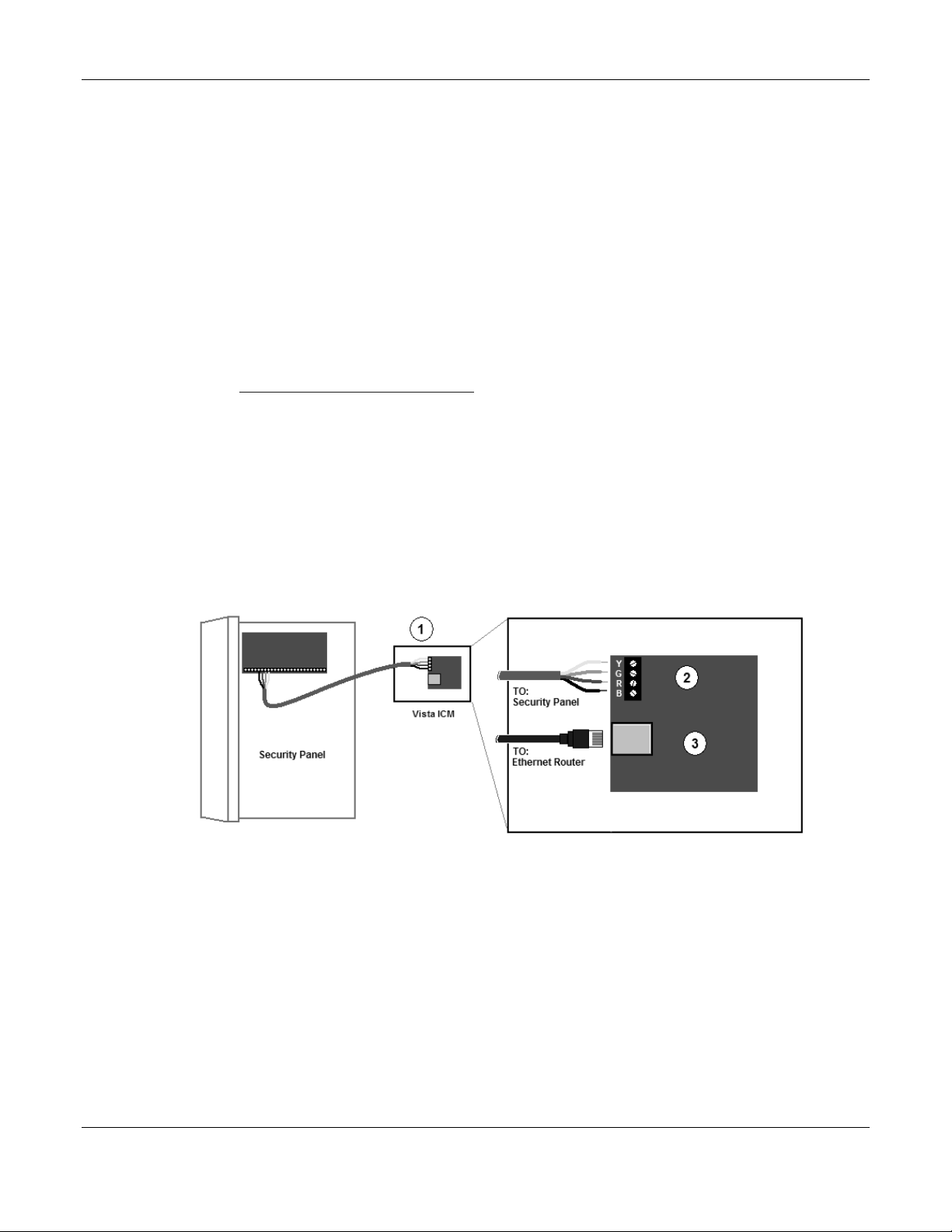
Installing VISTA-ICM Hardware
NOTE: Momentary depression of the VISTA-ICM reset button soft-resets the VISTAICM; a 5-second hold sets factory defaults, including static IP address if used.
To connect a VISTA-ICM:
in the address bar of the web browser to make
Figure 3 - VISTA-ICM Connections
1. Place the VISTA-ICM in a suitable clean, dry, ventilated indoor location, near the
equipment to be controlled. The VISTA-ICM is not designed to be installed in an
attic, crawl space, or an outdoor location.
2. Wire the VISTA-ICM to the Vista security panel using the keypad wiring guidelines
provided in the security panel instructions. The Vista VISTA-ICM is powered by the
Vista security panel, and requires 200mA from the Vista power supply.
NOTE: Supported security panels include any Vista control panel that supports
addressable keypads using ECP. Connect the Ethernet port on the VISTA-ICM to the
network hub or switch using a standard CAT5 cable.
NOTE: The VISTA-ICM does not support global features and must be assigned to a
particular partition.
4
Page 9

Configuring the VISTA-ICM
Connecting to the VISTA-ICM setup web pages
Once the network hardware is in place, you can initiate communication with the VISTAICM hardware. Use a PC or a tablet to connect to the VISTA-ICM web pages. To
connect to the VISTA-ICM, take the following actions:
1. Make sure the Vista VISTA-ICM is powered on by checking to see that the Power
LED is illuminated. Give the VISTA-ICM at least 60 seconds to boot up and obtain
an IP address from the router.
2. Open the web browser on the computer, and in the Address bar enter:
http://honeywell/setup
3. This will open the VISTA-ICM setup start page. Configure the VISTA-ICM
according to the instructions in the next section.
VISTA-ICM LEDs
The VISTA-ICM has three LEDs as follows:
• STATUS (located nearest the ECP connector) – Blinks when the device has activity.
• ETHERNET LINK (located in the middle) – Flickers when there is internet activity.
• POWER (located on the outside edge of the PCB) – Lit when power is applied to the
VISTA-ICM.
VISTA-ICM Installation and Setup Guide
5
Page 10
VISTA-ICM Installation and Setup Guide
VISTA-ICM Setup and Configuration
Basic VISTA-ICM Setup
VISTA-ICM setup is divided into two procedures:
• Select Devices
• Configure Devices
These procedures are accessed through the VISTA-ICM setup pages. The Navigation
bar on the left of the page allows direct access to any step in the process. Keep in mind
that changing the device setup will affect other settings and may require you to make
changes to programming or groups.
CAUTION: Only Internet Explorer, revision 5.0 or higher is supported. Use of other
browsers will give unpredictable results such as incorrect placement of objects or wrong
colors.
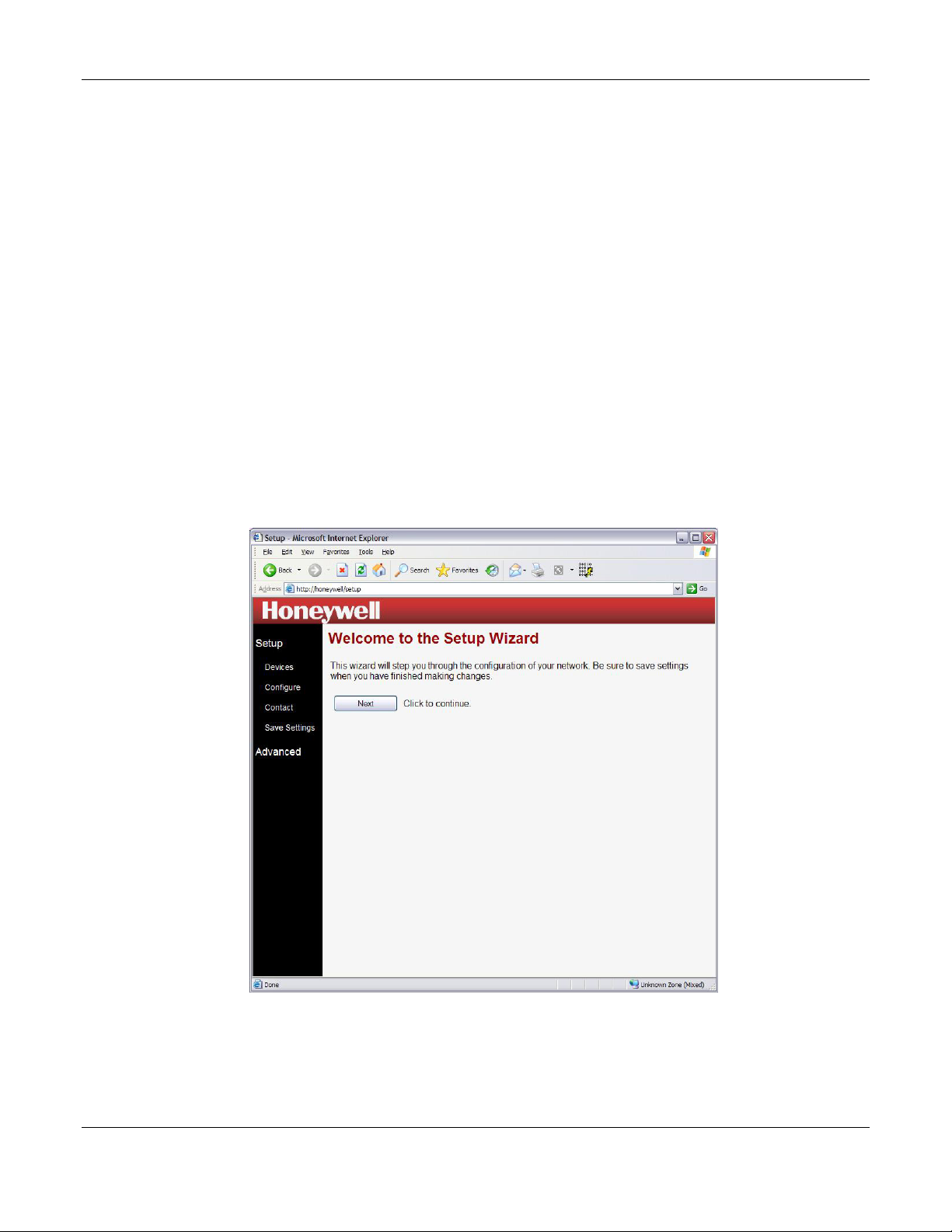
The wizard steps through all the procedures in order. Start the wizard by clicking the
Start Wizard button on the setup start page. The Setup Wizard page is displayed (figure
4).
CAUTION: Select devices before you perform any other setup task. When you select a
new device, it will be necessary to complete the configuration process again.
Figure 4 – Setup Wizard
NOTE: After the VISTA-ICM Setup is complete there is a link to exit setup and go
directly to the load control pages. To load the control pages click the link “Exit Setup
and Load Control Pages”.
6
Page 11

VISTA-ICM Installation and Setup Guide
Select Devices
The Device Setup page allows you to configure what specific equipment is controlled by
each VISTA-ICM in the network. Select the device controlled by each VISTA-ICM
before configuring anything else in the system. The device selection process is
performed using the following steps:
Click on Devices to bring up the Device Setup Node List page as shown in figure 5. This
page contains a list of all the devices in the system. The checkbox on the left side of the
page will contain a green checkmark for each device that has already been set up. Click
on the name of the first device in the list that has not been configured.
Figure 5 - Device Setup Node List
7
Page 12

VISTA-ICM Installation and Setup Guide
Figure 6 shows a list of ports on the VISTA-ICM. For each port in the list, perform the
following three steps:
1. In the column titled Device select the Name from the drop-down list that
matches the make and model of the device attached to that port. In some cases
the VISTA-ICM will auto-detect the connected device if it is powered on and
connected. If the device has already been detected, the information in the list
will already reflect the correct device.
Figure 6 - Device Setup - Port Assignment
2. In the Device Name column, enter the name you will use to identify the device.
If you leave the name blank, a default name will be used. It is best to use a
descriptive name that includes the room name if you plan to have more than one
device of the same type.
3. Click the Next button to submit the changes and return to the device selection
page. This will reset any prior configuration information for this VISTA-ICM,
and may require the device to be configured again.
When all the devices in the list have been assigned, click the Next button to proceed to
device configuration.
8
Page 13

VISTA-ICM Installation and Setup Guide
Configure Devices
The Configuration Setup page allows you to access custom configuration options specific
to the device or system controlled by the VISTA-ICM. Follow the configuration help
screens for each device to change the configuration. Once configuration is complete, the
changes must be saved to prevent data loss.
The configuration setup pages include help information specific to the tasks they
perform.
Figure 7 - Device Specific Configuration Page
9
Page 14

VISTA-ICM Installation and Setup Guide
This example shows the configuration options for the Vista security interface. Enter
text for the keypad function buttons, and select a device address that does not conflict
with other keypads on the ECP bus. Click the Next button to complete the
configuration process and move on to the next setup task.
NOTE: Only device addresses 16 through 23 may be used.
NOTE: Failure to press the Done button prior to performing Save Settings will cause
the changes to be lost.
Figure 8 - Vista Configuration - Security Page
NOTE: The keypad address specified must be enabled in the Vista Security Panel.
10
Page 15

VISTA-ICM Installation and Setup Guide
This example shows the Vista Email Configuration – Security options for the Vista
security interface. Select the Send email on event occurrences for which you wish to
have email notification.
CAUTION: Email alerts are meant just as a convenience, not for primary notification
of alarms.
Enter the Email address for which the alerts are to be sent. Click the Next button to
complete the configuration process and move on to the next setup task.
NOTE: Failure to press the Done button prior to performing Save Settings will cause
the changes to be lost.
Figure 9 - Vista Email Configuration - Security Page
11
Page 16

VISTA-ICM Installation and Setup Guide
This example shows the Zone Configuration – Security options for the Vista security
interface. Customize the Zone names to trigger actions on other devices in the network
such as turning on lights when a door opens. Trigger events are enabled for each Zone
that is assigned a custom name.
NOTE: Failure to press the Done button prior to performing Save Settings will cause
the changes to be lost.
Figure 10 – Zone Configuration - Security Page
12
Page 17

VISTA-ICM Installation and Setup Guide
Contact Information
The Contact Information page allows you to record and save contact information for the
dealer, installer or support organization for this system. Simply type in the appropriate
data for each line of information you want to store.
Figure 11 – Contact Information Page
13
Page 18

VISTA-ICM Installation and Setup Guide
Save Settings
Once the setup is complete, you must save the changes to make sure everything works
as configured after the VISTA-ICMs are restarted. The save process stores the settings
in permanent memory.
Click the Save button to save your changes. This will cause all ICMs on the network to
save changes, and will cause the system to be unresponsive for 10 to 15 seconds.
Figure 12 - Save Settings
CAUTION: If you do not save the setup, the changes you made will be lost when the
ICMs lose power.
NOTE: After the ICM Setup is complete there is a link to exit setup and go directly to
the control pages. To load the control pages click the link “Exit Setup and Load Control
Pages”.
14
Page 19

Advanced Setup
Advanced Setup contains the following utilities:
• Diagnostics - Shows detailed information about the nodes, including MAC address,
version, and configuration.
• File System - Allows you to load new files on to the node, and download files from
the node.
• Network - Change network related settings - set a static IP address, enable proxy
server or configure network time.
• Upgrade - Enables you to upgrade the node firmware to unlock new features and
capabilities.
• What's New - Links to the Internet for the latest information, software
applications, and news.
These utilities are accessed through the Advanced setup pages. The Navigation bar on
the left of the page allows direct access to any utility.
CAUTION: The advanced setup pages contain information and utilities that affect
system operation. Use care when changing advanced settings.
VISTA-ICM Installation and Setup Guide
15
Page 20

VISTA-ICM Installation and Setup Guide
Diagnostics
The Diagnostics page shows the complete list of all devices that have been discovered on
the network, including devices that are currently offline. The main diagnostic page lists
a table of information about all the VISTA-ICMs on the network.
Figure 13 - Diagnostics Node List
The fields on the diagnostic node list page include:
• Node # - The node number or VISTA-ICM number, based on the order the VISTA-
ICMs were installed on the network.
• Node Name – The name of each VISTA-ICM, based on the first device attached to
the VISTA-ICM.
• Type – This indicates the node type and manufacturer.
• IP – The IP address assigned to the VISTA-ICM.
• MAC – The Media Access Control address assigned to this VISTA-ICM by the
manufacturer.
• Home– This indicates if the VISTA-ICM is responding to “home” or “myhome” from
a local web browser.
• Status – This shows whether the device is online or offline.
16
Page 21

VISTA-ICM Installation and Setup Guide
If the VISTA-ICM is online, click on the IP address link to get more diagnostic
information about the VISTA-ICM.
Figure 14 - Diagnostic Details Page
The details page includes the following information:
• Time Online – This shows how long the VISTA-ICM has been running.
• Version/Date – This shows the build version of the firmware, devices and style
installed on this VISTA-ICM, as well as the date it was built.
• Restart – This button will restart the VISTA-ICM, and will reload the last saved
configuration.
• Reset – This button will erase all configuration information and restart the VISTAICM. If the VISTA-ICM is connected to a serial controlled device, and that device is
powered on, the VISTA-ICM will attempt to auto-detect the connected device type.
• Password – You can set a setup password, or clear the password from this page.
• Startup – You can change the default start page and options from this menu.
• Port List – This lists all the ports on the VISTA-ICM, and the device selected for
each port.
• Unit List – This lists all the units on the VISTA-ICM, from all ports on the VISTA-
ICM. A device may have several units if it performs several functions. For example
a combination DVD/VCR has two units, a DVD player and a VCR.
Each unit can have variables and commands. The Variables link shows all the
variables for that unit, and the commands link lists all the commands for that unit. If
the command exists, the link on the command will execute the command.
17
Page 22

VISTA-ICM Installation and Setup Guide
File System
The file system page allows you to access the files on any VISTA-ICM. The first page
shows a list of the nodes on the network. Click the node to access the file system page.
Figure 15 - File System Node List
18
Page 23

VISTA-ICM Installation and Setup Guide
The top section of the file system page allows you to load a file to the VISTA-ICM from a
web server. You can load any file to the VISTA-ICM including graphic images, device
files and web pages.
• Click the Browse button to locate a file on the local hard drive to upload.
• Click the Upload button to load the file to the VISTA-ICM. The file will show in the
file list.
The bottom section of the page shows the files that are already present on the VISTAICM. The log file is a system file that contains the boot log. The log file can be sent to
technical support as a troubleshooting aid. If you delete the log file, it will return the
next time the VISTA-ICM is booted.
Figure 16 - File System File List
The Style and Devices entries show the total file space used by the style and devices
directories. The style directory contains the graphics that make up the skin (or look and
feel) of the web pages served by the VISTA-ICM. The devices directory contains the
device specific drivers, web control pages and configuration pages.
You can delete the style and devices directories to make room to upload new style or
device files. If you do not load new style or devices files, the old files will be restored
when you save to flash or reboot the VISTA-ICM. To replace the directories, load a new
file named “style.tar.gz” or “devices.tar.gz” and click the save button to expand them.
CAUTION: Click the Save button to save the files to permanent memory. The files in
the file system are not saved as part of the basic setup save process.
19
Page 24

VISTA-ICM Installation and Setup Guide
Network Settings
The Network Settings page allows you to configure time settings for the network or
configure network settings for a specific node. Click the Configure System Time link
to access the NTP settings page (Figure 18) or the node link under the Node Name link
to access the Node Network Settings page (Figure 19).
Figure 17 – Network Settings Page
20
Page 25

VISTA-ICM Installation and Setup Guide
The NTP settings page allows you to select the Time Zone for the NTP server.
Figure 18 – NTP Settings Page
21
Page 26

VISTA-ICM Installation and Setup Guide
The Node Network Settings page allows you to enter the network settings for the node.
Figure 19 – Network Settings page (typical)
22
Page 27

VISTA-ICM Installation and Setup Guide
Upgrade
The Upgrade page will allow you to select any node on the network, and upgrade the
firmware. Firmware upgrades will be available periodically to enable new features and
add functionality. Click the link marked “Latest Version Info” to find out if there is a
new version of firmware available.
To upgrade a specific VISTA-ICM, select the node you want to upgrade from the list.
Click the Auto Update button to retrieve the latest version of firmware from the server
on the Internet. This requires the VISTA-ICM to be attached to the Internet. The
update process can take several minutes depending on the network connection speed.
The firmware image is typically larger than 1 megabyte.
NOTE: After a flash upgrade has been performed, you must reset the VISTA-ICM to
the factory defaults and perform the setup procedure again.
Figure 20 – Upgrade
23
Page 28

VISTA-ICM Installation and Setup Guide
What’s New
The What’s New link redirects to a page on the internet that contains information
about firmware updates, new products and new features. The new information is
located on the Internet, so an Internet connection is required for this feature.
Figure 21 – What’s New Page
24
Page 29

Troubleshooting
Troubleshooting an Ethernet home control network can be easy if you can divide and
conquer. See the following table to cut the problem in half.
Problem Resolution
Cannot access VISTA-ICM
web page
Can access VISTA-ICM
pages
Network Problems
If you cannot access the web page on the VISTA-ICM, there may be a network problem.
If you are having difficulty pinpointing the problem, just check the problems one by one
in order from top to bottom in the table below. Use the following chart to break the
problem down:
Problem Resolution
No Link Light on PC
No Link Light on Hub
PC cannot get an IP
address
PC cannot contact DHCP
Server
Invalid IP address
Tablet does not respond to
touch
VISTA-ICM LED functions
Computer cannot access
VISTA-ICM at
http://honeywell
VISTA-ICM Installation and Setup Guide
This is a network problem – see the Network Problems section to
resolve.
This is a device problem – see the Device Problems section to
resolve.
The link light is typically right next to the Ethernet (RJ-45) jack on
the PC, tablet, and the VISTA-ICM. The link light should turn on
when the PC is powered on and properly connected to an Ethernet
hub, switch or router. If the link light is off, check the Ethernet
cable
The link light on the hub (or router or switch) turns on when a PC
or VISTA-ICM is connected and powered on. If the link light is off,
check the Ethernet cable and power on the hub.
Most PCs get an IP address from the router using DHCP. Check
the PC documentation to make sure the PC is set to get an IP
address from DHCP. On Windows PCs, open a command prompt
and type “ipconfig” to view the IP address, or “ipconfig /renew”
to get a new IP address.
The network router contains the DHCP server. Make sure the
router or wireless router is installed properly. Check the router
documentation to turn on the DHCP server in the router setup
software.
An invalid IP address message normally only happens if a device
is set to use a static IP. Make sure no devices have static IP
address, and then reboot the offending device.
Tablet computer may need to be reset. Press and hold in the
large 5-way button for 8 seconds to power off the tablet. Wait 5
seconds, then press the button in and release to restart the tablet .
The VISTA-ICM LEDs perform the following functions from right to
left: 1. Power LED is on when power is applied to the VISTA-ICM.
2. Link LED is on when the VISTA-ICM is linked to a hub (and
flickers when data is transmitted). 3. Status LED flashes on and
off once per second once the VISTA-ICM gets a valid IP address
from the DHCP server.
Try to access the VISTA-ICM from a tablet or another computer.
The PC may have firewall software installed. Download the
findnode utility from http://in2nets.com/findnode.exe. Open a
command prompt (on a Windows PC) and run findnode to list the
IP addresses of the nodes on the network. Access the node using
an IP address reported by findnode.
25
Page 30

VISTA-ICM Installation and Setup Guide
Device Problems
If you can access the web pages on the VISTA-ICM but you are still having trouble, it
may be a device problem. If you are having difficulty pinpointing the problem, just
check the problems one by one in order from top to bottom in the table below. Use the
following chart to break the problem down:
Problem Resolution
Control page errors
Change button text
No feedback on control
page
Interaction with Security
No device control
No device feedback
No email
If the control page does not load correctly, refresh the page (F5 on
Microsoft Windows). In some cases after an upgrade you may
need to clear the browser cache to reset the web pages to normal
(Windows – Tools, Internet options).
If the button text on the control pages is incorrect, go to
http://honeywell/setup
configuration of the buttons.
The basic web pages use a Java applet to display real-time
feedback at the top of the control page. If this box is empty and
does not change, the Java plug-in may not be installed on the PC.
Go to http://www.java.com
(this is a free plug-in).
NOTE: After Java has been downloaded, the VISTA-ICM must be
defaulted and reconfigured.
If the device works from the control page, but does not interact
with security as desired, go to http://honeywell/setup
configuration to change the configuration of the system triggers.
If the buttons on the control page do not affect the device, check
the cable between the VISTA-ICM and the device. If the correct
cable is attached, check the setup/configuration page to make
sure the correct address information is entered. The Vista VISTAICM defaults to keypad address 23, and the Vista Security panel
must be configured with a keypad at address 23.
NOTE: Only device addresses 16 through 23 may be used.
If you can control the device but get no feedback, check the
diagnostics page. Click on the port variable information at the
bottom of the diagnostics page, and then look at the display
variable to see if it is updating properly (you must refresh the
variables by clicking on variable again). If the display variable
updates, see the problem “no feedback on control page”. If not,
replace the cable.
If the device does not send email alerts as desired, check the
errors in the log to see if the node reported a problem. Go to
http://honeywell/setup
View Log button.
, then configuration to change the
and download the Java virtual machine
, then
, then Advanced, Diagnostics and click the
26
Page 31

WARRANTY
For the latest warranty information, please go to:
http://www.security.honeywell.com/hsc/resources/wa
Page 32

2 Corporate Center Drive, Suite 100
Copyright © 2009 Honeywell International Inc.
ÊK14543V2?Š
K14543V2 2/09 Rev. A
P.O. Box 9040, Melville, NY 11747
www.honeywell.com/security
 Loading...